en 301 681 - v1.3.1 - satellite earth stations and systems (ses
TRANSCRIPT
ETSI EN 301 681 V1.3.1 (2002-05)
Candidate Harmonized European Standard (Telecommunications series)
Satellite Earth Stations and Systems (SES);Harmonized EN for Mobile Earth Stations (MESs) of
Geostationary mobile satellite systems, including handheldearth stations, for Satellite Personal Communications
Networks (S-PCN) in the 1,5/1,6 GHz bands under the MobileSatellite Service (MSS) covering essential requirements
under article 3.2 of the R&TTE Directive
ETSI
ETSI EN 301 681 V1.3.1 (2002-05)2
Reference REN/SES-00070
Keywords earth station, MES, mobile, MSS, multimode,
radio, S-PCN, satellite, service
ETSI
650 Route des Lucioles F-06921 Sophia Antipolis Cedex - FRANCE
Tel.: +33 4 92 94 42 00 Fax: +33 4 93 65 47 16
Siret N° 348 623 562 00017 - NAF 742 C
Association à but non lucratif enregistrée à la Sous-Préfecture de Grasse (06) N° 7803/88
Important notice
Individual copies of the present document can be downloaded from: http://www.etsi.org
The present document may be made available in more than one electronic version or in print. In any case of existing or perceived difference in contents between such versions, the reference version is the Portable Document Format (PDF).
In case of dispute, the reference shall be the printing on ETSI printers of the PDF version kept on a specific network drive within ETSI Secretariat.
Users of the present document should be aware that the document may be subject to revision or change of status. Information on the current status of this and other ETSI documents is available at
http://portal.etsi.org/tb/status/status.asp
If you find errors in the present document, send your comment to: [email protected]
Copyright Notification
No part may be reproduced except as authorized by written permission. The copyright and the foregoing restriction extend to reproduction in all media.
© European Telecommunications Standards Institute 2002.
All rights reserved.
DECTTM, PLUGTESTSTM and UMTSTM are Trade Marks of ETSI registered for the benefit of its Members. TIPHONTM and the TIPHON logo are Trade Marks currently being registered by ETSI for the benefit of its Members. 3GPPTM is a Trade Mark of ETSI registered for the benefit of its Members and of the 3GPP Organizational Partners.
ETSI
ETSI EN 301 681 V1.3.1 (2002-05)3
Contents
Intellectual Property Rights ................................................................................................................................6
Foreword.............................................................................................................................................................6
Introduction ........................................................................................................................................................7
1 Scope ........................................................................................................................................................9
2 References ................................................................................................................................................9
3 Definitions and abbreviations.................................................................................................................10 3.1 Definitions........................................................................................................................................................10 3.2 Abbreviations ...................................................................................................................................................11
4 Technical requirement specifications.....................................................................................................12 4.1 Environment profile .........................................................................................................................................12 4.1.1 General........................................................................................................................................................12 4.1.2 Temperature................................................................................................................................................12 4.1.3 Voltage........................................................................................................................................................12 4.1.4 Vibration.....................................................................................................................................................12 4.2 Conformance requirements ..............................................................................................................................13 4.2.1 Unwanted emissions outside the band 1 626,5 MHz to 1 660,5 MHz (carrier-on state) ............................13 4.2.1.1 Justification ...........................................................................................................................................13 4.2.1.2 Technical requirements .........................................................................................................................14 4.2.1.3 Conformance test ..................................................................................................................................15 4.2.2 Unwanted emissions within the bands 1 626,5 MHz to 1 660,5 MHz and 1 660,5 MHz to
1 662,5 MHz (carrier-on state)....................................................................................................................15 4.2.2.1 Justification ...........................................................................................................................................15 4.2.2.2 Technical requirements .........................................................................................................................15 4.2.2.3 Conformance test ..................................................................................................................................16 4.2.3 Unwanted emissions in carrier-off state......................................................................................................16 4.2.3.1 Justification ...........................................................................................................................................16 4.2.3.2 Technical requirements .........................................................................................................................17 4.2.3.3 Conformance test ..................................................................................................................................17 4.2.4 MES Control and Monitoring Functions (CMF) ........................................................................................17 4.2.4.1 Self-monitoring functions/Processor monitoring ..................................................................................17 4.2.4.1.1 Justification .....................................................................................................................................17 4.2.4.1.2 Technical requirements....................................................................................................................17 4.2.4.1.3 Conformance test.............................................................................................................................17 4.2.4.2 Self-monitoring functions/Transmit frequency generation sub-system monitoring..............................18 4.2.4.2.1 Justification .....................................................................................................................................18 4.2.4.2.2 Technical requirements....................................................................................................................18 4.2.4.2.3 Conformance test.............................................................................................................................18 4.2.4.3 Network control authorization ..............................................................................................................18 4.2.4.3.1 Justification .....................................................................................................................................18 4.2.4.3.2 Technical requirements....................................................................................................................18 4.2.4.3.3 Conformance test.............................................................................................................................18 4.2.4.4 Network control reception.....................................................................................................................18 4.2.4.4.1 Transmission disable/enable............................................................................................................18 4.2.4.4.1.1 Justification................................................................................................................................18 4.2.4.4.1.2 Technical requirements ..............................................................................................................19 4.2.4.4.1.3 Conformance test .......................................................................................................................19 4.2.4.4.2 Transmit frequency control .............................................................................................................19 4.2.4.4.2.1 Purpose ......................................................................................................................................19 4.2.4.4.2.2 Technical requirements ..............................................................................................................19 4.2.4.4.2.3 Conformance test .......................................................................................................................19 4.2.4.5 Fellow radio stations in a dual-mode or multimode terminal................................................................19 4.2.5.5.1 Justification .....................................................................................................................................19 4.2.4.5.2 Technical requirements....................................................................................................................19
ETSI
ETSI EN 301 681 V1.3.1 (2002-05)4
4.2.4.5.3 Conformance test.............................................................................................................................19 4.2.5 Equipment identity......................................................................................................................................20 4.2.5.1 Justification ...........................................................................................................................................20 4.2.5.2 Technical requirements .........................................................................................................................20 4.2.5.3 Conformance test ..................................................................................................................................20 4.2.6 Protection of the radio astronomy service operation in the band 1 660 MHz to 1 660,5 MHz...................20 4.2.6.1 Purpose..................................................................................................................................................20 4.2.6.2 Technical requirements .........................................................................................................................20 4.2.6.3 Conformance test ..................................................................................................................................20
5 Testing for compliance with technical requirements..............................................................................20 5.1 Environmental conditions for testing ...............................................................................................................20 5.1.1 Specification of the environmental test conditions .....................................................................................20 5.1.2 Tests under extreme voltage conditions......................................................................................................21 5.2 Essential radio test suites..................................................................................................................................21 5.2.1 General........................................................................................................................................................21 5.2.1.1 Description of equipment ......................................................................................................................21 5.2.1.2 Testing of host-connected equipment and plug-in modules ..................................................................22 5.2.1.2.1 Alternative approaches ....................................................................................................................22 5.2.1.2.2 Alternative A: combined equipment................................................................................................22 5.2.1.2.3 Alternative B: use of a test jig .........................................................................................................22 5.2.1.3 CMF/Special Test Equipment (STE) ....................................................................................................22 5.2.1.4 General test requirements......................................................................................................................23 5.2.1.4.1 MES test modes...............................................................................................................................23 5.2.1.4.2 Special Test Equipment (STE) ........................................................................................................23 5.2.1.4.2.1 Use of STE for control and monitoring functions tests..............................................................23 5.2.1.4.2.2 Test modulating signal ...............................................................................................................24 5.2.1.4.3 Laboratory Test Equipment (LTE) ..................................................................................................24 5.2.1.4.4 Methods of test for MES RF emissions according to the equipment type.......................................25 5.2.1.4.5 Procedures for measurement of radiated emissions.........................................................................25 5.2.1.4.5.1 General.......................................................................................................................................25 5.2.1.4.5.2 Test site ......................................................................................................................................25 5.2.1.4.5.3 Test set up for radiated emissions of the MES...........................................................................25 5.2.1.4.5.4 Reference position of the MES ..................................................................................................26 5.2.1.4.5.5 Measurement procedure for radiated emissions (peak)..............................................................26 5.2.1.4.5.5.1 Measurement procedure for peak radiated emissions of the MES .......................................26 5.2.1.4.5.5.2 Measurement procedure for peak radiated emissions of the cabinet ....................................28 5.2.1.4.5.6 Measurement procedure for radiated emissions (average).........................................................28 5.2.1.4.5.6.1 Measurement procedure for average radiated emissions of the MES...................................28 5.2.1.4.5.6.2 Measurement procedure for average radiated emissions of the cabinet ...............................29 5.2.1.4.6 Procedures for measurement of conducted emissions .....................................................................30 5.2.1.4.6.1 General.......................................................................................................................................30 5.2.1.4.6.2 Test site ......................................................................................................................................30 5.2.1.4.6.3 Test set-up..................................................................................................................................30 5.2.1.4.6.4 Measurement procedure for conducted emissions (peak) ..........................................................30 5.2.1.4.6.5 Measurement procedure for conducted emissions (average) .....................................................31 5.2.1.4.7 Interpretation of the measurement results........................................................................................31 5.2.1.4.8 Test report........................................................................................................................................31 5.2.2 Unwanted emissions outside the band 1 626,5 MHz to 1 660,5 MHz (carrier-on state) ............................31 5.2.2.1 Method of test .......................................................................................................................................31 5.2.2.2 Peak measurement.................................................................................................................................32 5.2.2.3 Average measurement ...........................................................................................................................32 5.2.2.4 Test requirements ..................................................................................................................................33 5.2.3 Unwanted emissions within the band 1 626,5 MHz to 1 660,5 MHz and the band 1 624,5 MHz to
1 626,5 MHz and 1 660,5 MHz to 1 662,5 MHz (carrier-on state).............................................................33 5.2.3.1 Method of test .......................................................................................................................................33 5.2.3.2 Measurement method ............................................................................................................................33 5.2.3.3 Test requirements ..................................................................................................................................34 5.2.4 Unwanted emissions in carrier-off state......................................................................................................34 5.2.4.1 Method of test .......................................................................................................................................34 5.2.4.2 Measurement method ............................................................................................................................34 5.2.4.3 Test requirements ..................................................................................................................................35
ETSI
ETSI EN 301 681 V1.3.1 (2002-05)5
5.2.5 MES Control and Monitoring Functions (CMF) ........................................................................................35 5.2.5.1 Self-monitoring functions/Processor monitoring ..................................................................................35 5.2.5.2 Self-monitoring functions/Transmit frequency generation sub-system monitoring..............................35 5.2.5.3 Network control authorization ..............................................................................................................35 5.2.5.3.1 Method of test..................................................................................................................................35 5.2.5.3.2 Test procedure .................................................................................................................................35 5.2.5.3.3 Test requirement..............................................................................................................................36 5.2.5.4 Network control reception.....................................................................................................................36 5.2.5.4.1 Transmission disable/enable............................................................................................................36 5.2.5.4.1.1 Method of test ............................................................................................................................36 5.2.5.4.1.2 Test procedure............................................................................................................................36 5.2.5.4.1.3 Test requirement ........................................................................................................................37 5.2.5.4.2 Transmit frequency control .............................................................................................................37 5.2.5.4.2.1 Method of test ............................................................................................................................37 5.2.5.4.2.2 Test procedure............................................................................................................................37 5.2.5.4.2.3 Test requirement ........................................................................................................................37 5.2.5.5 Fellow radio stations in a dual-mode or multimode terminal................................................................38 5.2.5.5.1 Method of test..................................................................................................................................38 5.2.5.5.2 Test procedure .................................................................................................................................38 5.2.5.5.3 Test requirements ............................................................................................................................38 5.2.6 Equipment identity......................................................................................................................................38 5.2.6.1 Method of test .......................................................................................................................................38 5.2.6.2 Test procedure.......................................................................................................................................38 5.2.6.3 Test requirements ..................................................................................................................................38
Annex A (normative): The EN Requirements Table (EN-RT) ........................................................39
Annex B (informative): Bibliography...................................................................................................41
Annex C (informative): The EN title in the official languages ...........................................................42
History ..............................................................................................................................................................43
ETSI
ETSI EN 301 681 V1.3.1 (2002-05)6
Intellectual Property Rights IPRs essential or potentially essential to the present document may have been declared to ETSI. The information pertaining to these essential IPRs, if any, is publicly available for ETSI members and non-members, and can be found in ETSI SR 000 314: "Intellectual Property Rights (IPRs); Essential, or potentially Essential, IPRs notified to ETSI in respect of ETSI standards", which is available from the ETSI Secretariat. Latest updates are available on the ETSI Web server (http://webapp.etsi.org/IPR/home.asp).
Pursuant to the ETSI IPR Policy, no investigation, including IPR searches, has been carried out by ETSI. No guarantee can be given as to the existence of other IPRs not referenced in ETSI SR 000 314 (or the updates on the ETSI Web server) which are, or may be, or may become, essential to the present document.
Foreword This Candidate Harmonized European Standard (Telecommunications series) has been produced by ETSI Technical Committee Satellite Earth Stations and Systems (SES), and is now submitted for the Public Enquiry phase of the ETSI standards Two-step Approval Procedure.
The present document has been produced by ETSI in response to a mandate from the European Commission issued under Council Directive 98/34/EC [7] (as amended) laying down a procedure for the provision of information in the field of technical standards and regulations.
The present document is intended to become a Harmonized Standard, the reference of which will be published in the Official Journal of the European Communities referencing the Directive 1999/5/EC of the European Parliament and of the Council of 9 March 1999 on radio equipment and telecommunications terminal equipment and the mutual recognition of their conformity ("the R&TTE Directive") [1].
Technical specifications relevant to Directive 1999/5/EC [1] are given in annex A.
Proposed national transposition dates
Date of latest announcement of this EN (doa): 3 months after ETSI publication
Date of latest publication of new National Standard or endorsement of this EN (dop/e):
6 months after doa
Date of withdrawal of any conflicting National Standard (dow): 18 months after doa
ETSI
ETSI EN 301 681 V1.3.1 (2002-05)7
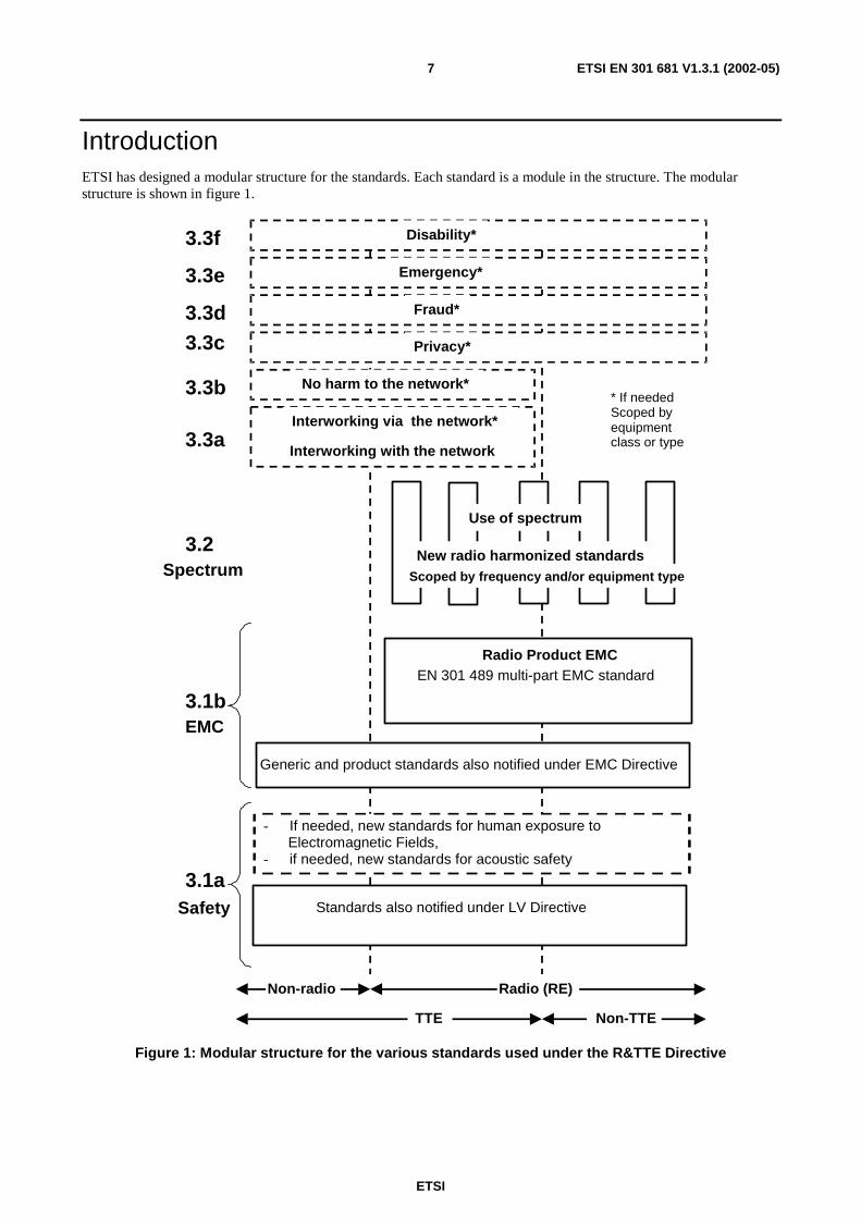
Introduction ETSI has designed a modular structure for the standards. Each standard is a module in the structure. The modular structure is shown in figure 1.
- If needed, new standards for human exposure to Electromagnetic Fields,
- if needed, new standards for acoustic safety
Use of spectrum
* If needed Scoped by equipment class or type
Scoped by frequency and/or equipment type
Disability*
Privacy*
Fraud*
No harm to the network*
Emergency*
Interworking via the network*
Interworking with the network
Non-radio Radio (RE)
Non-TTE TTE
3.1b
3.2
3.3c
3.3b
3.3a
3.3d
3.3e
3.3f
Radio Product EMC
EN 301 489 multi-part EMC standard
Generic and product standards also notified under EMC Directive
Standards also notified under LV Directive
3.1a
New radio harmonized standards Spectrum
EMC
Safety
Figure 1: Modular structure for the various standards used under the R&TTE Directive

ETSI
ETSI EN 301 681 V1.3.1 (2002-05)8
The left hand edge of the figure 1 shows the different clauses of article 3 of the R&TTE Directive [1].
For article 3.3 various horizontal boxes are shown. Dotted lines indicate that at the time of publication of the present document essential requirements in these areas have to be adopted by the Commission. If such essential requirements are adopted, and as far and as long as they are applicable, they will justify individual standards whose scope is likely to be specified by function or interface type.
The vertical boxes show the standards under article 3.2 for the use of the radio spectrum by radio equipment. The scopes of these standards are specified either by frequency (normally in the case where frequency bands are harmonized) or by radio equipment type.
For article 3.1b the diagram shows EN 301 489, the multi-part product EMC standard for radio used under the EMC Directive [2].
For article 3.1a the diagram shows the existing safety standards currently used under the LV Directive [3] and new standards covering human exposure to electromagnetic fields. New standards covering acoustic safety may also be required.
The bottom of the figure shows the relationship of the standards to radio equipment and telecommunications terminal equipment. A particular equipment may be radio equipment, telecommunications terminal equipment or both. A radio spectrum standard will apply if it is radio equipment. An article 3.3 standard will apply as well only if the relevant essential requirement under the R&TTE Directive [1] is adopted by the Commission and if the equipment in question is covered by the scope of the corresponding standard. Thus, depending on the nature of the equipment, the essential requirements under the R&TTE Directive [1] may be covered in a set of standards.
The modularity principle has been taken because:
• it minimizes the number of standards needed. Because equipment may, in fact, have multiple interfaces and functions it is not practicable to produce a single standard for each possible combination of functions that may occur in an equipment;
• it provides scope for standards to be added:
- under article 3.2 when new frequency bands are agreed; or
- under article 3.3 should the Commission take the necessary decisions;
without requiring alteration of standards that are already published;
• it clarifies, simplifies and promotes the usage of Harmonized Standards as the relevant means of conformity assessment.
The technical requirements in the present document are applied under article 3.2 of the R&TTE Directive, concerning the effective uses of the spectrum allocated to terrestrial/space radio communication and orbital resources so as to avoid harmful interference. These requirements are in two major categories:
emissions limits: to protect other radio services from harmful interference generated by the MES in normal use;
MES Control and Monitoring Functions (CMF): to protect other radio services from unwanted transmissions from the MES. The CMF in each MES is capable of answering to commands from the Network Control Facilities (NCF) for its S-PCN.
NOTE: The requirements for Network Control Facilities (NCF) for S-PCN are contained in EN 301 682 [6].
The determination of the parameters of the user earth stations using a given satellite for the protection of the spectrum allocated to that satellite, is considered to be under the responsibility of the satellite operator or the satellite network operators.
ETSI
ETSI EN 301 681 V1.3.1 (2002-05)9
1 Scope The present document applies to S-PCN MES for Geostationary mobile satellite systems with an EIRP less than or equal to 15 dBW.
The present document sets out the minimum performance requirements and technical characteristics of Mobile Earth Stations (MES) with both transmit and receive capabilities for operation in a Satellite Personal Communication Network (S-PCN) in the Mobile Satellite Service (MSS) frequency band given in table 1.
Table 1: Mobile Satellite Service (MSS) frequency band
Transmission path MSS frequency band MESs transmit 1 626,5 MHz to 1 660,5 MHz MESs receive 1 525 MHz to 1 559 MHz
An S-PCN MES may be handheld, portable, vehicle-mounted, host connected, semi-fixed or fixed equipment, or may be an element in a multimode terminal; it may consist of a number of modules with associated connections and user interface, or may be a self contained single unit.
If the MES is an element in a multimode terminal, unless otherwise stated in the present document, its requirements apply only to the S-PCN MES element of the terminal operating in the MSS frequency band given in table 1.
The present document is intended to cover the provisions of Directive 1999/5/EC [1] (R&TTE Directive) article 3.2 which states that "….radio equipment shall be so constructed that it effectively uses the spectrum allocated to terrestrial/space radio communications and orbital resources so as to avoid harmful interference".
In addition to the present document, other ENs that specify technical requirements in respect of essential requirements under other parts of article 3 of the R&TTE Directive [1] may apply to equipment within the scope of the present document.
NOTE 1: A list of such ENs is included on the web site http://www.newapproach.org/.
NOTE 2: These MESs are controlled and monitored by a Network Control Facility (NCF). The NCF is outside the scope of the present document.
2 References The following documents contain provisions which, through reference in this text, constitute provisions of the present document.
• References are either specific (identified by date of publication and/or edition number or version number) or non-specific.
• For a specific reference, subsequent revisions do not apply.
• For a non-specific reference, the latest version applies.
[1] Directive 1999/5/EC of the European Parliament and of the Council of 9 March 1999 on radio equipment and telecommunications terminal equipment and the mutual recognition of their conformity (R&TTE Directive).
[2] Council Directive 89/336/EEC of 3 May 1989 on the approximation of the laws of the Member States relating to electromagnetic compatibility (EMC Directive).
[3] Council Directive 73/23/EEC of 19 February 1973 on the harmonization of the laws of Member States relating to electrical equipment designed for use within certain voltage limits (LV Directive).
[4] ITU-T Recommendation O.153 (10/92): "Basic parameters for the measurement of error performance at bit rates below the primary rate"

ETSI
ETSI EN 301 681 V1.3.1 (2002-05)10
[5] CISPR 16-1 Amd.1: "Specification for radio disturbance and immunity measuring apparatus and methods - Part 1: Radio disturbance and immunity measuring apparatus " (annex G: Validation of the open area test site for the frequency range of 30 MHz to 1 000 MHz).
[6] ETSI EN 301 682: "Satellite Personal Communications Networks (S-PCN); Network Control Facilities (NCF) for Mobile Earth Stations (MESs), including handheld earth stations, for S-PCN in the 1,5/1,6 GHz bands, providing voice and/or data communications under the Mobile Satellite Service (MSS)".
[7] Directive 98/34/EC of the European Parliament and of the Council of 22 June 1998 laying down a procedure for the provision of information in the field of technical standards and regulations.
3 Definitions and abbreviations
3.1 Definitions For the purpose of the present document, the terms and definitions given in the R&TTE Directive [1], and the following apply:
applicant: manufacturer or his authorized representative within the European Community or the person responsible for placing the apparatus on the market
carrier-on time (initial bursts): period when an MES is transmitting a signal. For MESs that transmit in a non-continuous mode, the carrier-on time only includes the times when the MES is transmitting a signal.
carrier-on state: MES is in this state when it is authorized by the NCF to transmit and when it transmits a signal.
carrier-off state: MES is in this state when either it is authorized by the Network Control Facility (NCF) to transmit but when it does not transmit any signal, or when it is not authorized by the NCF to transmit.
conducted measurement: measurement of emissions from an antenna port of the MES made by direct wired connection to the port
environmental profile: range of environmental conditions under which equipment within the scope of the present document is required to comply with the provisions of the present document
Equivalent Isotropically Radiated Power (EIRP): product of transmitter power and the antenna gain in the direction considered, relative to an isotropic source radiating uniformly in all directions
fellow radio station: one of the (other) modes of a multimode MES
handheld: indicates an MES which is self-contained and is small enough and light enough to be carried and used during a call with one hand
host-connected: indicates an MES for which connection to or integration with host equipment is necessary to offer functionality
host equipment: any equipment which has a complete user functionality when not connected to the MES, and to which the MES provides additional functionality, and to which connection is necessary for the MES to offer functionality
Installable Equipment (IE), Internally Mounted Equipment (IME) and Externally Mounted Equipment (EME): Installable Equipment (IE) is an equipment which is intended to be installed in a vehicle. An IE may consist of one or several interconnected modules. The IE is composed of modules intended to be externally mounted as declared by the applicant, and defined as Externally Mounted Equipment (EME) and the remaining modules(s) as Internally Mounted Equipment (IME).
Laboratory Test Equipment (LTE): logical grouping that contains the standard test equipment provided by a test laboratory
MSS band: continuous range of frequencies allocated by the ITU to the MSS
multimode: indicates equipment that accommodates radio stations of different radio networks
ETSI
ETSI EN 301 681 V1.3.1 (2002-05)11
network control channel: channel by which an MES receives general control information from the NCF of its S-PCN
NCF control message: message, normally originating from a network, to a specified terminal or set of terminals of the network which indicates to the terminal or set of terminals that it/they should carry out some specific action or should enter or maintain some specific state
NOTE: For test purposes NCF control messages may originate from Special Test Equipment (STE).
nominated bandwidth (Bn): The nominated bandwidth of the MES radio frequency transmission is nominated by the applicant. The nominated bandwidth is wide enough to encompass all spectral elements of the transmission necessary for communication and which have a level greater than the specified unwanted emissions limits. The nominated bandwidth is wide enough to take account of the transmit carrier frequency stability. The nominated bandwidth is centred on the transmit frequency and does not exceed 180 % of the 3dB bandwidth of the signal. The nominated bandwidth is within the assigned part of the MSS transmit frequency band within which the MES operates.
3dB Bandwidth (B3dB): total width of the signal spectrum 3 dB below the maximum in-band density
operational frequency range(s): sub-portion(s) of the band 1 626,5 MHz to 1 660,5 MHz in the earth-to-space direction to the MSS network, for which the equipment has been designed as declared by the applicant
Portable Equipment (PE): equipment generally intended to be self-contained, free standing and portable. A PE would normally consist of a single module, but may consist of several interconnected modules
radiated measurement: measurement of an actual radiated field
Special Test Equipment (STE): equipment which allows a test laboratory to control the MES so that the tests required by the present document can be performed
test laboratory: laboratory which performs the conformance testing of the MES against the present document. The test laboratory may be the applicant's laboratory
test load: substantially non-reactive, non-radiating power attenuator which is capable of safely dissipating the power from the transmitter(s)
transmission format: physical characteristics of the signal that is transmitted by an MES. An MES may use more than one transmission format within a single S-PCN
unwanted emissions: emissions falling outside the nominated bandwidth in the carrier-on state and those generated in the carrier-off state
3.2 Abbreviations For the purposes of the present document, the following abbreviations apply:
ASD Acceleration Spectral Density B3dB 3dB Bandwidth
Bn Nominated Bandwidth
CDMA Code Division Multiple Access CMF Control and Monitoring Functions dBW deciBels relative to 1 Watt EIRP Equivalent Isotropically Radiated Power EMC Electro-Magnetic Compatibility EME Externally Mounted Equipment IE Installable Equipment IEC International Electrotechnical Commission/Committee IME Internally Mounted Equipment ITU International Telecommunications Union LTE Laboratory Test Equipment
ETSI
ETSI EN 301 681 V1.3.1 (2002-05)12
LV Low Voltage MES Mobile Earth Station MIC MES Identification Code MSS Mobile Satellite Service NCF Network Control Facility PE Portable Equipment R&TTE Radio and Telecommunications Terminal Equipment RF Radio Frequency S-PCN Satellite Personal Communications Network STE Special Test Equipment TDMA Time Division Multiple Access
4 Technical requirement specifications
4.1 Environment profile
4.1.1 General
The technical requirements of the present document apply under the environmental profile specified below for operation of the equipment. The equipment shall comply with all the technical requirements of the present document at all times when operating within the boundary limits of the specified operational environmental profile.
4.1.2 Temperature
The MES shall fulfil all the requirements in the full temperature ranges of:
-10°C to +55°C.
NOTE: This range is taken from IEC 60068-2-1 and IEC 60068-2-2 (see bibliography).
4.1.3 Voltage
The applicant shall declare the nominal, lower and the higher extreme voltages.
The MES shall fulfil all the requirements in the full voltage range between the extreme voltages.
4.1.4 Vibration
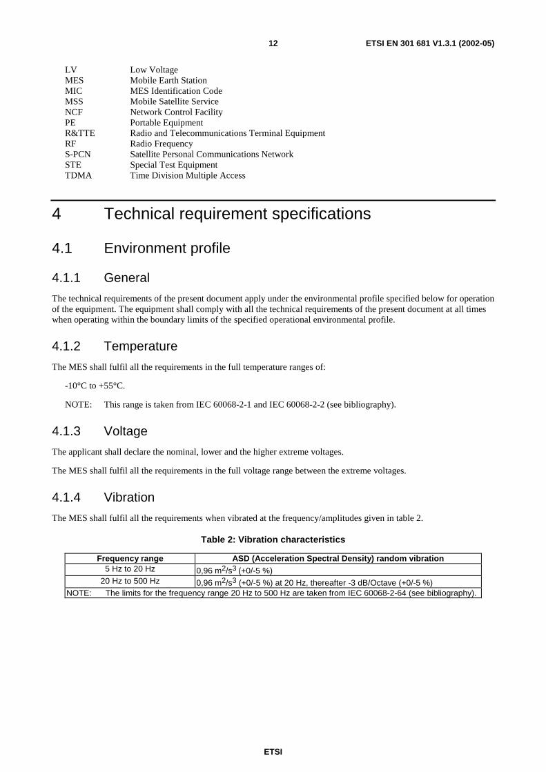
The MES shall fulfil all the requirements when vibrated at the frequency/amplitudes given in table 2.
Table 2: Vibration characteristics
Frequency range ASD (Acceleration Spectral Density) random vibration 5 Hz to 20 Hz 0,96 m2/s3 (+0/-5 %)
20 Hz to 500 Hz 0,96 m2/s3 (+0/-5 %) at 20 Hz, thereafter -3 dB/Octave (+0/-5 %) NOTE: The limits for the frequency range 20 Hz to 500 Hz are taken from IEC 60068-2-64 (see bibliography).
ETSI
ETSI EN 301 681 V1.3.1 (2002-05)13
4.2 Conformance requirements
4.2.1 Unwanted emissions outside the band 1 626,5 MHz to 1 660,5 MHz (carrier-on state)
4.2.1.1 Justification
Protection of other radio services operating outside the band 1 626,5 MHz to 1 660,5 MHz from emissions caused by S-PCN MESs operating within the band 1 626,5 MHz to 1 660,5 MHz.
ETSI
ETSI EN 301 681 V1.3.1 (2002-05)14
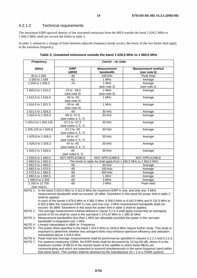
4.2.1.2 Technical requirements
The maximum EIRP spectral density of the unwanted emissions from the MES outside the band 1 626,5 MHz to 1 660,5 MHz shall not exceed the limits in table 3.
In table 3, whenever a change of limit between adjacent frequency bands occurs, the lower of the two limits shall apply at the transition frequency.
Table 3: Unwanted emissions outside the band 1 626,5 MHz to 1 660,5 MHz
Frequency Carrier - on state
(MHz) EIRP (dBW)
Measurement bandwidth
Measurement method (see note 6)
30 to 1 000 -66 100 kHz Peak Hold 1 000 to 1 559 -61 1 MHz Average
1 559 to 1 605,0 -70 1 MHz (see note 3)
Average (see note 2)
1 605,0 to 1 612,5 -70 to - 58,5 (see note 4)
1 MHz (see note 3)
Average
1 612,5 to 1 616,5 -55 to -50 (see note 4)
1 MHz Average
1 616,5 to 1 621,5 -50 to -46 (see note 4)
1 MHz Average
1 621,5 to 1 624,5 -60 30 kHz Average 1 624,5 to 1 625,0 -60 to -57,5
(see notes 4, 5, 7) 30 kHz Average
1 625,0 to 1 625,125 -57,5 to -57,2 (see notes 4, 5, 7)
30 kHz Average
1 625,125 to 1 625,8 -57,2 to -50 (see notes 4, 5, 7)
30 kHz Average
1 625,8 to 1 626,0 -50 to -47 (see notes 4, 5, 7)
30 kHz Average
1 626,0 to 1 626,2 -47 to -40 (see notes 4, 5, 7)
30 kHz Average
1 626,2 to 1 626,5 -40 (see notes 5, 7)
30 kHz Average
1 626,5 to 1 660,5 NOT APPLICABLE NOT APPLICABLE NOT APPLICABLE 1 660,5 to 1 662,5 The levels in table 4a shall apply from 1 660,5 MHz to 1 662,5 MHz 1 662,5 to 1 665,5 -60 30 kHz Average 1 665,5 to 1 670,5 -60 100 kHz Average 1 670,5 to 1 680,5 -60 300 kHz Average 1 680,5 to 1 690,5 -60 1 MHz Average 1 690,5 to 2 250 -60 3 MHz Average 2 250 to 12 750
(see note1) -60 3 MHz Peak Hold
NOTE 1: In the band 3 253,0 MHz to 3 321,0 MHz the maximum EIRP in one, and only one, 3 MHz measurement bandwidth shall not exceed -45 dBW. Elsewhere in this band the power limit in table 3 shall be applied.
In each of the bands 4 879,5 MHz to 4 981,5 MHz, 6 506,0 MHz to 6 642,0 MHz and 8 132,5 MHz to 8 302,5 MHz the maximum EIRP in one, and only one, 3 MHz measurement bandwidth shall not exceed -55 dBW. Elsewhere in this band the power limit in table 3 shall be applied.
NOTE 2: The average measurement method defined in clause 5.2.2.3 shall apply except that an averaging period of 20 ms shall be used in the sub-band 1 573,42 MHz to 1 580,42 MHz.
NOTE 3: Measurement bandwidths less than 1 MHz are allowable provided the power in the narrower bandwidth is integrated over 1 MHz.
NOTE 4: Linearly interpolated in dBW vs. Frequency. NOTE 5: The power limits specified in the band 1 624,5 MHz to 1626,5 MHz require further study. This study is
important to determine whether less stringent limits may enhance spectrum efficiency and utilization immediately above 1 626,5 MHz.
NOTE 6: Peak Hold and Average measurements shall be performed as specified in clauses 5.2.2.2 and 5.2.2.3. NOTE 7: For systems employing CDMA, the EIRP limits shall be decreased by 10 log (N) dB, where N is the
maximum number of MESs in the receive beam of the satellite to which these MESs are communicating and which are expected to transmit simultaneously in the same frequency band within that same beam. This number shall be declared by the manufacturer (N = 1 in a TDMA system).
ETSI
ETSI EN 301 681 V1.3.1 (2002-05)15
The conformance requirements apply for the full range of environmental conditions corresponding to the type of equipment as specified in clause 4.1.
4.2.1.3 Conformance test
Conformance tests shall be carried out in accordance with clause 5.2.2.
4.2.2 Unwanted emissions within the bands 1 626,5 MHz to 1 660,5 MHz and 1 660,5 MHz to 1 662,5 MHz (carrier-on state)
4.2.2.1 Justification
Protection of radio services and systems operating within the neighbouring frequency band 1 660,5 MHz to 1 662,5 MHz and other systems operating within the band 1 626,5 MHz to 1 660,5 MHz from unwanted emissions caused by S-PCN MESs operating in the band 1 626,5 MHz to 1 660,5 MHz.
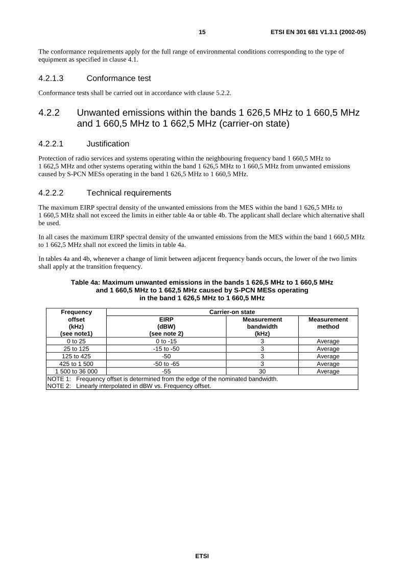
4.2.2.2 Technical requirements
The maximum EIRP spectral density of the unwanted emissions from the MES within the band 1 626,5 MHz to 1 660,5 MHz shall not exceed the limits in either table 4a or table 4b. The applicant shall declare which alternative shall be used.
In all cases the maximum EIRP spectral density of the unwanted emissions from the MES within the band 1 660,5 MHz to 1 662,5 MHz shall not exceed the limits in table 4a.
In tables 4a and 4b, whenever a change of limit between adjacent frequency bands occurs, the lower of the two limits shall apply at the transition frequency.
Table 4a: Maximum unwanted emissions in the bands 1 626,5 MHz to 1 660,5 MHz and 1 660,5 MHz to 1 662,5 MHz caused by S-PCN MESs operating
in the band 1 626,5 MHz to 1 660,5 MHz
Frequency Carrier-on state offset (kHz)
(see note1)
EIRP (dBW)
(see note 2)
Measurement bandwidth
(kHz)
Measurement method
0 to 25 0 to -15 3 Average 25 to 125 -15 to -50 3 Average
125 to 425 -50 3 Average 425 to 1 500 -50 to -65 3 Average
1 500 to 36 000 -55 30 Average NOTE 1: Frequency offset is determined from the edge of the nominated bandwidth. NOTE 2: Linearly interpolated in dBW vs. Frequency offset.

ETSI
ETSI EN 301 681 V1.3.1 (2002-05)16
Table 4b: Maximum unwanted emissions in the bands 1 626,5 MHz to 1 660,5 MHz caused by S-PCN MESs operating in the band 1 626,5 MHz to 1 660,5 MHz
Frequency Carrier-on state offset (kHz)
(see notes 1, 3)
EIRP (dBW)
(see note 2)
Measurement bandwidth
(kHz)
Measurement method
0 to 25 0 to -15 3 Average 25 to 55 -15 to -25
(see note 4) 3 Average
55 to AB -25 (see note 4)
3 Average
AB to (AB + 0,35 x B3dB)
-25 to -40 (see note 4)
3 Average
(AB + 0,35 x B3dB)
to CD
-40 3 Average
CD to (CD + 0,25 x B3dB)
-40 to -50 3 Average
(CD + 0,25 x B3dB)
to EF
-50 3 Average
EF to 1 500 -50 to -65 3 Average 1 500 to 36 000 -55 30 Average
NOTE 1: Frequency offset is determined from the edge of the nominated bandwidth. NOTE 2: Linearly interpolated in dBW vs. Frequency offset. NOTE 3: The parameters AB, CD, EF are defined below. NOTE 4: The limit of -25 dBW in this table is determined on the assumption that the adjacent channel
interference results from a single interferer. This limit shall apply to MESs that are designed for operation in a network where the occurrence of two (or more) interferers, all transmitting with the maximum permitted level of unwanted emissions, does not exceed 0,1 % of the time; otherwise a limit of -30 dBW shall apply.
The parameters AB, CD and EF are defined as a proportion of the 3dB Bandwidth as follows:
AB = (55) or (100 % of the B3dB), whichever is the greater;
CD = (95) or (200 % of the B3dB), whichever is the greater;
EF = (125) or (300 % of the B3dB), whichever is the greater.
For systems employing CDMA, the EIRP limits in tables 4a, and 4b shall be decreased by 10 x log (N) dB, where N is the maximum number of MESs in the receive beam of the satellite to which these MESs are communicating and which are expected to transmit simultaneously in the same frequency band within that same beam. This number shall be declared by the applicant.
NOTE: N = 1 in a TDMA system.
The conformance requirements apply for the full range of environmental conditions corresponding to the type of equipment as specified in clause 4.1.
4.2.2.3 Conformance test
Conformance tests shall be carried out in accordance with clause 5.2.3.
4.2.3 Unwanted emissions in carrier-off state
4.2.3.1 Justification
Protection of other radio services and systems from unwanted emissions caused by MESs in the carrier-off state.

ETSI
ETSI EN 301 681 V1.3.1 (2002-05)17
4.2.3.2 Technical requirements
The maximum EIRP spectral density of the unwanted emissions from the MESs in the carrier-off state shall not exceed the limits in table 5.
In table 5, whenever a change of limit between adjacent frequency bands occurs, the lower of the two limits shall apply at the transition frequency.
Table 5: Maximum EIRP spectral density of the unwanted emissions in the carrier-off state
Frequency (MHz)
EIRP (dBW)
Measurement bandwidth
Measurement method
30 to 1 000 -87 100 kHz peak hold 1 000 to 1 525 -77 100 kHz peak hold 1 525 to 1 559 -97
(see note 3) 100 kHz average
1 559 to 1 610 -70 1 MHz (see note 1)
Average (see note 2)
1 610 to 12 750 -77 100 kHz peak hold NOTE 1: Measurement bandwidths less than 1 MHz are allowable provided the power in the
narrower bandwidth is integrated over 1 MHz. NOTE 2: The average measurement method defined in clause 5.2.2.3. shall apply except that a
measurement time of 20 ms shall be used in the sub-band 1 573,42 MHz to 1 580,42 MHz.
NOTE 3: If MES antenna gain is higher than 8 dBi, the unwanted emission limit in the band 1 525 MHz to 1 559 MHz shall be considered to be -90 dBW in 100 kHz.
The conformance requirements apply for the full range of environmental conditions corresponding to the type of equipment as specified in clause 4.1.
4.2.3.3 Conformance test
Conformance tests shall be carried out in accordance with clause 5.2.4.
4.2.4 MES Control and Monitoring Functions (CMF)
4.2.4.1 Self-monitoring functions/Processor monitoring
4.2.4.1.1 Justification
Protection of radio services and systems from uncontrolled RF transmissions from the MES.
4.2.4.1.2 Technical requirements
The MES shall incorporate a processor monitoring function for each of its processors involved in the manipulation of traffic and in control and monitoring functions.
The processor monitoring function shall detect failure of the processor hardware and software.
Not later than 1 s after any detectable fault condition occurs, the transmissions shall be suppressed (carrier-off state) until the processor monitoring function has determined that all fault conditions have been cleared.
The fault conditions which cause transmission shutdown shall be specified by the applicant and declared by the applicant.
The conformance requirements apply for the environmental conditions as specified in clause 4.1.
4.2.4.1.3 Conformance test
Conformance tests shall be carried out in accordance with clause 5.2.5.1.
ETSI
ETSI EN 301 681 V1.3.1 (2002-05)18
4.2.4.2 Self-monitoring functions/Transmit frequency generation sub-system monitoring
4.2.4.2.1 Justification
Protection of radio services and systems from uncontrolled RF transmissions from the MES.
4.2.4.2.2 Technical requirements
The MES shall incorporate a transmit frequency generation sub-system monitoring function.
Not later than 5 s after any detectable failure of the transmit frequency generation sub-system occurs, the transmissions shall be suppressed (carrier-off state) until the transmit frequency generation sub-system monitoring function has determined that all fault conditions have been cleared.
The fault conditions which cause transmission shutdown shall be specified by the applicant and declared by the applicant.
The conformance requirements apply for the environmental conditions as specified in clause 4.1.
4.2.4.2.3 Conformance test
Conformance tests shall be carried out in accordance with clause 5.2.5.2.
4.2.4.3 Network control authorization
4.2.4.3.1 Justification
Protection of radio services and systems from uncontrolled RF transmissions from the MES.
4.2.4.3.2 Technical requirements
During power-on no transmissions shall occur from the MES.
Following power-on the MES shall enter the carrier-off state. This state shall be maintained whilst the MES is not synchronized with the appropriate network control channel(s).
Without synchronizing to the appropriate network control channel(s), it shall not be possible to initiate the carrier-on state.
Within 30 s of having lost the appropriate network control channel(s) the MES shall suppress transmissions (carrier-off state).
The conformance requirements apply for the environmental conditions as specified in clause 4.1.
4.2.4.3.3 Conformance test
Conformance tests shall be carried out in accordance with clause 5.2.5.3.
4.2.4.4 Network control reception
4.2.4.4.1 Transmission disable/enable
4.2.4.4.1.1 Justification
Protection of radio services and systems from uncontrolled RF transmissions from the MES.
ETSI
ETSI EN 301 681 V1.3.1 (2002-05)19
4.2.4.4.1.2 Technical requirements
After power-on the MES shall remain in the carrier-off state until it receives a transmission enable command. For systems where no transmission enable command is expected after power-on the MES may only transmit initial bursts.
An MES which is in the carrier-on state shall not continue transmissions for a period of time longer than 1 s after receipt of a transmission disable command. After ceasing transmissions the MES shall enter the carrier-off state until it receives a transmission enable command. For systems where no transmission enable command is expected after receipt of a transmission disable command the MES may only transmit initial bursts.
The initial bursts shall be subject to the following restrictions:
a) an initial burst may be transmitted in a continuous or non-continuous mode (i.e. as a single burst or as a sequence of bursts);
b) the carrier-on time of an initial burst transmission sequence shall not exceed one second;
c) the total carrier-on time for multiple initial bursts shall not exceed 1 % of the time.
The conformance requirements apply for the environmental conditions as specified in clause 4.1.
4.2.4.4.1.3 Conformance test
Conformance tests shall be carried out in accordance with clause 5.2.5.4.1.
4.2.4.4.2 Transmit frequency control
4.2.4.4.2.1 Purpose
Protection of radio services and systems from uncontrolled RF transmissions from the MES.
4.2.4.4.2.2 Technical requirements
The MES shall set the carrier frequency of its transmission according to the command of the NCF. The carrier frequency has to be controlled such, that the entire nominated bandwidth of the terminal falls completely within the operational frequency range(s) specified by the applicant and declared by the applicant.
The conformance requirements apply for the environmental conditions as specified in clause 4.1.
4.2.4.4.2.3 Conformance test
Conformance tests shall be carried out in accordance with clause 5.2.5.4.2.
4.2.4.5 Fellow radio stations in a dual-mode or multimode terminal
4.2.5.5.1 Justification
Protection of radio services and systems from uncontrolled RF transmissions from the MES.
4.2.4.5.2 Technical requirements
Any fellow radio station in a multimode MES shall not transmit without reception of the appropriate network control channel(s) for the system for which it is designed. The conformance requirements apply for the environmental conditions as specified for the fellow radio station.
4.2.4.5.3 Conformance test
Conformance tests shall be carried out in accordance with clause 5.2.5.5.

ETSI
ETSI EN 301 681 V1.3.1 (2002-05)20
4.2.5 Equipment identity
4.2.5.1 Justification
Protection of radio services and systems from uncontrolled RF transmissions from the MES.
4.2.5.2 Technical requirements
Each MES shall have a unique MES Identification Code (MIC) within its S-PCN.
It shall not be possible for the user to alter the MIC using any normally accessible procedure.
The MES shall be capable of transmitting its MES Identification Code upon reception of an appropriate NCF command addressed to it.
The conformance requirements apply for the environmental conditions as specified in clause 4.1.
4.2.5.3 Conformance test
Conformance tests shall be carried out in accordance with clause 5.2.6.
4.2.6 Protection of the radio astronomy service operation in the band 1 660 MHz to 1 660,5 MHz
4.2.6.1 Purpose
To protect the radio astronomy service in the 1 660 MHz to 1 660,5 MHz band from emissions produced by MESs.
4.2.6.2 Technical requirements
The MES shall be able to have its transmissions disabled as specified in clause 4.2.4.4.1.
The actual procedure used in an S-PCN network to protect the radio astronomy service in the 1 660 MHz to 1 660,5 MHz band may utilize additional features of the MES.
4.2.6.3 Conformance test
Conformance tests shall be carried out in accordance with clause 5.2.5.4.1.
5 Testing for compliance with technical requirements
5.1 Environmental conditions for testing
5.1.1 Specification of the environmental test conditions
The tests in clauses 5.2.2, 5.2.3, 5.2.4, 5.2.5 and 5.2.6 shall be performed under the conditions given in table 6.
Table 6: Environmental test conditions
Equipment Category Temperature Voltage Handheld Normal Normal condition voltage (±1 %) other than handheld Normal Higher extreme voltage (+0/-2 %) other than handheld Normal Lower extreme voltage (-0/+2 %)
Normal temperature shall be between +15°C and +35°C.
ETSI
ETSI EN 301 681 V1.3.1 (2002-05)21
All other tests shall be performed under normal conditions for temperature and voltage, and without vibration.
5.1.2 Tests under extreme voltage conditions
During tests under extreme voltage conditions, the power source of the equipment shall be replaced by a test power source, capable of producing extreme test voltages as specified in clause 5.1.1. The internal impedance of the test power source shall be low enough for its effect on the test results to be negligible. For the test purposes, the voltage of the power source shall be measured at the input terminals of the equipment.
If the equipment is provided with a permanently connected power cable, the test voltage shall be measured at the point of connection of the power cable to the equipment.
In equipment with incorporated batteries, the test power source shall be applied as close to the battery terminals as is practical. In each case connections shall be made readily available by the applicant.
During tests, the power source voltages shall be maintained within a tolerance of ±3 % relative to the voltage at the beginning of each test.
5.2 Essential radio test suites
5.2.1 General
5.2.1.1 Description of equipment
The applicant shall provide a statement which contains all of the information related to the MES and its testing environment.
This shall include:
• self contained or host-connected;
• single mode or multimode;
• antenna:
- active or;
- passive, with an antenna port available; or
- passive, no antenna port available;
• the method by which the equipment can be switched into its test modes;
• the fault conditions which cause transmission shut-down;
• the nominal, the lower extreme and the higher extreme operational voltages;
• the transmission formats for which the different EIRP spectral density limits apply and the maximum gross data rate at which the MES is designed to operate for each of those formats;
• the value(s) of nominated bandwidth for each transmission format for that S-PCN;
• the value(s) of the 3 dB bandwidth for each transmission format for that S-PCN;
• in an information leaflet, for each S-PCN for which the MES is designed to operate:
a) the name of the S-PCN;
b) the operating frequency range(s) of the MES;
c) the frequency sub-bands and operating conditions for which the different EIRP spectral density limits apply;
ETSI
ETSI EN 301 681 V1.3.1 (2002-05)22
NOTE 1: In the case of a multimode MES, the other modes of operation shall be stated.
NOTE 2: If the MES has an active antenna, the antenna is regarded as an integral part of the MES and the antenna port if available shall not be used for testing.
NOTE 3: If the MES is intended for use with a passive antenna, the maximum gain of any antenna intended to be used with the equipment is to be stated.
NOTE 4: If conducted emissions measurements are to be performed, at the choice of the applicant:, the maximum antenna gain at the frequency of particular measured spurious emissions may be stated.
NOTE 5: If Special Test Equipment (STE) is required see clause 5.2.1.4.2.
NOTE 6: Transmission formats include all relevant differences in the format of the transmitted data e.g. the different modulations schemes and/or burst sizes that are used within the relevant S-PCN.
5.2.1.2 Testing of host-connected equipment and plug-in modules
5.2.1.2.1 Alternative approaches
For equipment for which connection to or integration with host equipment is required to offer functionality, two alternative approaches are permitted. The applicant shall declare which alternative shall be used.
5.2.1.2.2 Alternative A: combined equipment
Under alternative A, a combination of MES and a specific type of host equipment shall be used for testing according to the present document.
Where more than one such combination is intended, testing shall not be repeated for combinations of MES and other host equipment where the latter are substantially similar, in particular such that the host models are unlikely to significantly influence the emissions of the MES.
Where more than one such combination is intended and host equipment are not substantially similar, one combination shall be tested against the full set of requirements of the present document; other combinations shall be tested separately for radiated emissions only.
5.2.1.2.3 Alternative B: use of a test jig
Under alternative B, where the MES is intended for use with a variety of host equipment, the applicant shall supply a suitable test jig that is representative of the range of host equipment in which the MES may be used In particular, the test jig shall be designed such that any alteration of the MES's emissions is minimized. The test jig shall allow the MES part to be powered and stimulated in a way similar to the way it would be powered and stimulated when connected to or inserted into the host equipment.
The MES shall be tested against the full set of requirements of the present document.
5.2.1.3 CMF/Special Test Equipment (STE)
The STE shall provide the necessary facilities for tests which require that the MES be operated in its normal operating manner, situated in an environment where receipt of the appropriate network control channel(s) and of NCF commands is under the control of the test laboratory.
The STE shall also provide means for the test laboratory to interface its test equipment with the MES for the purpose of monitoring the MES responses.
For other tests, where the required test mode cannot be, or is not, provided by a special test facility within the MES, then the STE shall also provide the facility to put the MES into these required test modes.

ETSI
ETSI EN 301 681 V1.3.1 (2002-05)23
5.2.1.4 General test requirements
5.2.1.4.1 MES test modes
The MES is required to be placed in a number of different test modes in order for the various tests specified within the present document to be carried out:
1) power-off;
2) power-on (applies to all the following test modes);
3) carrier-off state;
4) carrier-on state, maximum transmit power, in a specified channel within the operational frequency range(s), transmitting with a specified transmission format and modulated with the test modulating signal as specified in clause 5.2.1.4.2.2;
5) carrier-on state, maximum transmit power, in a specified channel within the operational frequency range(s), set by NCF command, transmitting with a specified transmission format and modulated with the test modulating signal as specified in clause 5.2.1.4.2.2;
NOTE: If this is available for all tests (4) is not required separately.
6) carrier-on state at any detectable power.
The MES may be placed into test modes 4 and 5 either by means of a special facility existing internally in the MES, or by means of a Special Test Equipment (STE).
If the MES has been modified by the applicant for these tests, then full documentation showing such modification(s) shall be provided to demonstrate that the modification(s) will not cause the test results to deviate from normal operational performance.
5.2.1.4.2 Special Test Equipment (STE)
5.2.1.4.2.1 Use of STE for control and monitoring functions tests
The test arrangement shall be as shown in figure 2 for radiated and conducted measurements.
This test arrangement assumes that the STE is responsible for simulating for the MES the NCF commands or network control channel in the same way as they are received by the MES in normal operating mode. The response received by the STE from the MES shall be routed to the LTE without modification that would significantly affect the measurement.

ETSI
ETSI EN 301 681 V1.3.1 (2002-05)24
Spectrumanalyser
Powermeter
Oscilloscope
MES
LTE
STE
Signal
Spectrumanalyser
Powermeter
Oscilloscope
MES
LTE
STE
Signal
Radiated test Conducted test
TriggerTrigger
Signal/Commands/ResponsesSignal/Commands/Responses
Figure 2: General test arrangement for control and monitoring tests
The dual trace storage oscilloscope, or other suitable method, may be used to monitor the response of the MES to the simulated events by measuring the time difference between the event or command reception, and the compliance with that event.
The power meter and spectrum analyser shall be used to monitor the MES output signal during all the test procedure.
5.2.1.4.2.2 Test modulating signal
The test modulating signal is a baseband signal which modulates the carrier of the MES and is dependent upon the type of equipment under test. It is a signal representing a pseudorandom bit sequence of at least 511 bits in accordance with ITU-T Recommendation O.153 [4]. This sequence shall be continuously repeated and shall be at the maximum bit rate declared by the applicant at which the MES is able to operate.
If not internally generated by the MES, this test modulating signal shall be provided by the STE.
5.2.1.4.3 Laboratory Test Equipment (LTE)
The Laboratory Test Equipment (LTE) is a logical grouping that contains the measurement equipment provided by the test laboratory.
It shall be verified that the responses of the LTE, including any test antenna, to a constant amplitude sine wave signal remain within ±1 dB of calibration across the frequency range of interest.
The maximum values of measurement uncertainty for the LTE associated with each measurement parameter given in table 7 for a 95 % confidence level, shall apply as appropriate to the test cases described in the present document.
Table 7: Measurement uncertainties
Measured parameter Measurement uncertainty Radio Frequency above 1 MHz ±1 part in 107
EIRP spectral density within the operational frequency range(s)
±0,75 dB
Unwanted radiated emissions ±6 dB Unwanted conducted emissions ±4 dB
ETSI
ETSI EN 301 681 V1.3.1 (2002-05)25
5.2.1.4.4 Methods of test for MES RF emissions according to the equipment type
Measurements shall be performed according to the equipment type as defined in table 8.
Table 8: Options for testing
Equipment with passive antenna port available (external, internal or temporary)
Radiated from cabinet from 30 MHz to 4 GHz (passive antenna port connected to a dummy load), and conducted from the passive antenna port, from 100 kHz to 12,75 GHz.
Equipment with no passive antenna port available (see note)
Radiated from complete MES, including its antenna, from 30 MHz to 12,75 GHz.
NOTE: Equipment with an active antenna shall be assumed to have no antenna port available.
The methods of measurement for radiated emissions are described in clause 5.2.1.4.5.
The methods of measurement for conducted emissions are described in clause 5.2.1.4.6.
5.2.1.4.5 Procedures for measurement of radiated emissions
5.2.1.4.5.1 General
Clause 5.2.1.4.5 contains methods for tests involving the measurement of a radiated field. This field may be radiated by an antenna and/or by the cabinet of the equipment itself.
It is recognized that for some parameters, alternative test methods may exist. It is the responsibility of the test laboratory to ensure that any alternative test method used yields results identical to those described in the present document.
5.2.1.4.5.2 Test site
The standard test site shall be a calibrated open air test site, whose dimensions are appropriate to the frequency range of measurements according to the specification of CISPR 16-1 [5].
All radiated measurement tests shall be conducted in such a way as to ensure that there is no interference to operational satellite and terrestrial systems. In some cases operating on a test site may produce electromagnetic perturbation or, conversely, external radiation may disturb the measurement. For these reasons, and also in order to reduce the space required, or to perform tests under extreme environmental conditions, other arrangements may be used, such as:
• anechoic chamber;
• indoor test site.
In addition, it shall be verified that the test site shall be suitable with respect to ambient noise which shall be at least 6 dB lower than the lowest specification value being measured.
The methods of measurement described in this annex are based on an open air test site. If an anechoic chamber or an indoor test site are used, some changes may apply to the method of measurement. For each radiated measurement, the nature and the dimensions of the test arrangement used shall be recorded in the test report.
5.2.1.4.5.3 Test set up for radiated emissions of the MES
The tests shall be carried out with the MES at the specified environmental conditions and for the specified power supply voltages.
For IE, EME and IME it shall be installed with a separation of approximately 0,5 m. Between the two equipment, the maximum length connection cable specified by the applicant shall be installed. The height of the cable shall be between 0,5 m and 1 m. The cable shall be maintained in that position by non-metallic means. The EME shall be set, in its normal operating configuration on a non-conducting support at a height between 0,5 m and 1 m. The IME shall be set on a non-conducting support at a height between 0,5 m and 1 m. Any associated equipment, if required for normal operation of the MES, shall be placed next to, and at the same height as the IME.
For PE, the equipment shall be arranged in its normal operating configuration as recommended by the applicant on a non-metallic table at a height between 0,5 m and 1 m.

ETSI
ETSI EN 301 681 V1.3.1 (2002-05)26
The MES under test shall be placed on the support in its standard position and shall be switched-on.
Each antenna (MES antenna and test antenna) shall be positioned to be outside the near field of the other antenna.
The spectrum analyser noise floor shall be at least 6 dB below the minimum value to be measured.
5.2.1.4.5.4 Reference position of the MES
During radiated measurements, the MES is required to be oriented specifically in relation to the test antenna connected to the LTE. This position is called the reference position and is determined as follows:
• the MES shall be placed in a mode whereby it is transmitting;
• the MES shall be rotated in both horizontal and vertical planes in order to locate the direction of maximum field strength that is detected by the test antenna. This orientation shall be called the reference position.
5.2.1.4.5.5 Measurement procedure for radiated emissions (peak)
5.2.1.4.5.5.1 Measurement procedure for peak radiated emissions of the MES
1
2
3
Ground plane
0,5 m to 1 m
Specified height range
0,5 m to 4 m
4
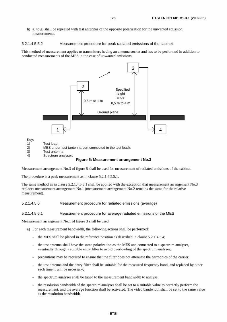
Key: 1) MES under test (with antenna); 2) Test antenna; 3) Input filter (if necessary); 4) Spectrum analyser.
Figure 3: Measurement arrangement No.1
Measurement arrangement No.1 of figure 3 shall be used.
a) For each measurement bandwidth, the following actions shall be performed:
- The MES shall be placed in the reference position as described in clause 5.2.1.4.5.4.
- The test antenna shall have the same polarization as the MES and connected to a spectrum analyser, eventually through a suitable entry filter to avoid overloading of the spectrum analyser.
- Precautions may be required to ensure that the filter does not attenuate the harmonics of the carrier.
- The test antenna and the entry filter shall be suitable for the measured frequency band, and replaced by other each time it will be necessary.
- The spectrum analyser shall be tuned to the measurement bandwidth to analyse.
- The resolution bandwidth of the spectrum analyser shall be set to a suitable value to correctly perform the measurement, and the peak hold function shall be activated. The video bandwidth shall be set to at least 3 times the resolution bandwidth.

ETSI
ETSI EN 301 681 V1.3.1 (2002-05)27
b) Only the discrete signals having a level equal or greater than 6 dB below the specified limit shall be precisely measured.
- The test antenna shall be raised or lowered through the specified height range to look for the maximum signal on the spectrum analyser (this may not be necessary if the test site is an anechoic chamber or an indoor test site).
- The maximum measured value shall be recorded.
c) The procedure is repeated from a) to b) with the other measurement bandwidths to cover all the frequency range to be analysed.
d) In the case where the test site has been calibrated before, the absolute measurement is sufficient to determine the actual value of EIRP of the radiated emissions. The precise knowledge of distance between the MES and the test antenna, and the characteristics of the test antenna and the input filter allow the determination of the EIRP radiated by the MES.
e) In the case where the test site cannot be calibrated, a relative measurement can be done according to the following procedure:
2
3
4 1
Ground plane
0,5 m to 1 m
Specified height range
0,5 m to 4 m
Key: 1) Sinusoidal RF signal generator; 2) Substitution antenna; 3) Test antenna; 4) Spectrum analyser.
Figure 4: Measurement arrangement No.2
Using measurement arrangement No.2 of figure 4, a substitution antenna shall replace the MES in the same position where was the MES antenna. It shall be connected to the signal generator.
f) The signal generator shall be tuned to each frequency at which an emission has been detected in the case of unwanted emissions measurement, or to the frequency at the middle of each measurement bandwidth in the case of EIRP spectral density measurement, the substitution antenna shall be suitable for this frequency.
- The spectrum analyser shall be tuned to the measurement bandwidth to analyse and put in the same conditions as for the measurement with the MES, with the peak hold function activated.
- The level of the signal generator shall be adjusted to give the same signal level on the spectrum analyser as in b).
- The output level of the signal generator shall be recorded. This value, after corrections due to the gain of the substitution antenna and the cable loss between the signal generator and the substitution antenna, is the radiated emission level of the MES.
g) The f) procedure is repeated with the other measurement bandwidths to cover the whole frequency range to be analysed.
ETSI
ETSI EN 301 681 V1.3.1 (2002-05)28
h) a) to g) shall be repeated with test antennas of the opposite polarization for the unwanted emission measurements.
5.2.1.4.5.5.2 Measurement procedure for peak radiated emissions of the cabinet
This method of measurement applies to transmitters having an antenna socket and has to be performed in addition to conducted measurements of the MES in the case of unwanted emissions.
2
3
4 1
Ground plane
0,5 m to 1 m
Specified height range
0,5 m to 4 m
Key: 1) Test load; 2) MES under test (antenna port connected to the test load); 3) Test antenna; 4) Spectrum analyser.
Figure 5: Measurement arrangement No.3
Measurement arrangement No.3 of figure 5 shall be used for measurement of radiated emissions of the cabinet.
The procedure is a peak measurement as in clause 5.2.1.4.5.5.1.
The same method as in clause 5.2.1.4.5.5.1 shall be applied with the exception that measurement arrangement No.3 replaces measurement arrangement No.1 (measurement arrangement No.2 remains the same for the relative measurement).
5.2.1.4.5.6 Measurement procedure for radiated emissions (average)
5.2.1.4.5.6.1 Measurement procedure for average radiated emissions of the MES
Measurement arrangement No.1 of figure 3 shall be used.
a) For each measurement bandwidth, the following actions shall be performed:
- the MES shall be placed in the reference position as described in clause 5.2.1.4.5.4;
- the test antenna shall have the same polarization as the MES and connected to a spectrum analyser, eventually through a suitable entry filter to avoid overloading of the spectrum analyser;
- precautions may be required to ensure that the filter does not attenuate the harmonics of the carrier;
- the test antenna and the entry filter shall be suitable for the measured frequency band, and replaced by other each time it will be necessary;
- the spectrum analyser shall be tuned to the measurement bandwidth to analyse;
- the resolution bandwidth of the spectrum analyser shall be set to a suitable value to correctly perform the measurement, and the average function shall be activated. The video bandwidth shall be set to the same value as the resolution bandwidth.
ETSI
ETSI EN 301 681 V1.3.1 (2002-05)29
b) The test antenna shall be raised or lowered through the specified height range to look for the maximum received signal on the spectrum analyser (this step may not be necessary if the test site is an anechoic chamber or an indoor test site).
- The EIRP shall be averaged until the variance over the measured bandwidth is less than 1 dB. The averaged value shall be recorded.
c) The procedure shall be repeated from a) to b) with the other measurement bandwidths to cover the whole frequency range to be analysed.
d) In the case where the test site has been calibrated before, the absolute measurement is sufficient to determine the actual value of EIRP of the radiated emissions. The precise knowledge of distance between the MES and the test antenna, the characteristics of the test antenna and the input filter allow the determination of the EIRP radiated by the MES.
e) In the case where the test site cannot be calibrated, a relative measurement can be done according to the following procedure:
- using measurement arrangement No.2 of figure 4, a substitution antenna shall replace the MES in the same position where was the MES antenna. It shall be connected to the signal generator.
f) The signal generator shall be tuned to the centre frequency of each measurement bandwidth. The substitution antenna shall be suitable for this frequency.
- The spectrum analyser shall be tuned to the measurement bandwidth to analyse and put in the same conditions as for the measurement with the MES with the average function activated.
- The level of the signal generator shall be adjusted to give the same signal level on the spectrum analyser as in b) when averaged until the variance over the measured bandwidth is less than 1 dB. The output level of the signal generator shall be recorded.
- This value, after corrections due to the gain of the substitution antenna and the cable loss between the signal generator and the substitution antenna, is the radiated emission level of the MES.
g) The f) procedure shall be repeated with the other measurement bandwidths to cover the whole frequency range to be analysed.
h) a) to g) shall be repeated with test antennas of the opposite polarization for the unwanted emission measurements.
5.2.1.4.5.6.2 Measurement procedure for average radiated emissions of the cabinet
This method of measurement applies to transmitters having an antenna socket and has to be performed in addition to conducted measurements of the MES for unwanted emissions.
Measurement arrangement No.3 of figure 5 shall be used for measurement of radiated emissions of the cabinet.
The procedure is an average measurement as in clause 5.2.1.4.5.6.1.
The same method as in clause 5.2.1.4.5.6.1 shall be applied with the exception that measurement arrangement No.3 replaces measurement arrangement No.1 (measurement arrangement No.2 remains the same for the relative measurement).

ETSI
ETSI EN 301 681 V1.3.1 (2002-05)30
5.2.1.4.6 Procedures for measurement of conducted emissions
5.2.1.4.6.1 General
Clause 5.2.1.4.6 contains the procedure for conducted emission measurements.
It is recognized that for some parameters, alternative test methods may exist. It is the responsibility of the test laboratory to ensure that any alternative test method used yields results identical to those described in the present document.
5.2.1.4.6.2 Test site
There are no specific requirements for the test site for conducted measurements except that they shall be performed in such a way as to ensure that there is no interference to operational satellite and terrestrial systems.
5.2.1.4.6.3 Test set-up
Measurement arrangement of figure 6 shall be used.
generator
Test load Filter
Spectrum
Analyser
EUT
RF signal
Figure 6: Measurement arrangement for conducted emissions
The antenna port of the MES shall be connected to a spectrum analyser through a test load and eventually an appropriate filter to avoid overloading of the spectrum analyser.
Precautions may be required to ensure that the test load does not generate or that the filter does not attenuate, the harmonics of the carrier. The entry filter shall be suitable for the measured frequency band, and replaced by another each time it will be necessary.
The spectrum analyser noise floor shall be at least 6 dB below the minimum value to be measured.
5.2.1.4.6.4 Measurement procedure for conducted emissions (peak)
a) For each measurement bandwidth, the following actions shall be performed:
- The spectrum analyser shall be tuned to the measurement bandwidth to analyse.
- The resolution bandwidth of the spectrum analyser shall be set to a suitable value to correctly perform the measurement, and the peak hold function shall be activated. The video bandwidth shall be set to at least 3 times the resolution bandwidth.
b) The peak power detected value of each discrete signal having a level equal or greater than 6 dB below the specified limit shall be recorded.
- In the case of EIRP spectral density measurement within the nominated bandwidth, the peak power density value within the measurement bandwidth shall be recorded.
ETSI
ETSI EN 301 681 V1.3.1 (2002-05)31
c) The procedure shall be repeated from a) to b) with the other measurement bandwidths to cover all the spectrum band(s) which are required to be measured.
d) The actual value of EIRP of the equivalent radiated emissions in each measurement bandwidth shall be derived by adding either the MES maximum antenna gain or the declared gain at the spurious emission frequency to the power value read from the spectrum analyser.
5.2.1.4.6.5 Measurement procedure for conducted emissions (average)
a) For each measurement bandwidth, the following actions shall be performed:
The resolution bandwidth of the spectrum analyser shall be set to a suitable value to correctly perform the measurement, and the average function shall be activated. The video bandwidth shall be set to the same value as the resolution bandwidth.
The measurement time should be such that the difference of the measured levels, averaged over subsequent measurement samples, is less than 1 dB, or a measurement time of 100 ms may be used if the measured values comply with the applicable limits.
b) The averaged power density value within the measured bandwidth shall be recorded.
c) The procedure shall be repeated from a) to b) with the other measurement bandwidths to cover the whole frequency range to be analysed.
d) The actual value of EIRP of the radiated emissions in each measurement bandwidth shall be derived by adding the MES maximum antenna gain measured at the normal operating frequency to the power spectral density value read from the spectrum analyser.
5.2.1.4.7 Interpretation of the measurement results
The interpretation of the results for the measurements described in the present document shall be as follows:
a) the measured value related to the corresponding limit shall be used to decide whether an equipment meets the minimum requirements of the standard;
b) the actual measurement uncertainty of the test laboratory carrying out the measurement, for each particular measurement, shall be included in the test report;
c) the values of the actual measurement uncertainty shall be, for each measurement, equal to or lower than the figures in clause 5.2.1.4.3.
5.2.1.4.8 Test report
All results of the tests performed shall be recorded in a test report.
For each test, the test report shall also include the test conditions (status of the MES, frequency of operation), the measurement uncertainties and the environmental test conditions.
5.2.2 Unwanted emissions outside the band 1 626,5 MHz to 1 660,5 MHz (carrier-on state)
5.2.2.1 Method of test
This test shall be carried out for the minimum and for the maximum MES transmit frequencies for which the MES is designed to operate, as specified by the applicant.
If the MES supports multiple transmission formats, each of the relevant transmission formats shall be tested at each frequency.
The transmit frequencies and the transmission formats used for the test shall be entered in the test report.
The environmental test conditions are given in clause 5.1.

ETSI
ETSI EN 301 681 V1.3.1 (2002-05)32
For each test, the MES shall be set to transmit (carrier-on state) on one of the specified transmitting frequencies to be tested and in one of the specified transmission formats to be tested and shall be set to transmit at its maximum power for that transmit frequency and transmission format, by means of the STE or by another test facility provided by the applicant.
If there is a handover function in the MES (to allow change of frequency channel during a call), this function shall be disabled.
The transmitted carrier shall be modulated by a test signal as specified in clause 5.2.1.4.2.2.
In the test equipment, the spectrum analyser noise floor shall be at least 6 dB below the appropriate limits given in table 3.
The measurements are performed with the radiated or with the conducted method according to the cases defined in clause 5.2.1.4.4.
For measurements of radiated unwanted emissions, clause 5.2.1.4.5 applies.
For measurements of conducted unwanted emissions, clause 5.2.1.4.6 applies.
5.2.2.2 Peak measurement
In the case of peak measurement, the spectrum analyser shall be set in sweep mode and shall be operated under the following conditions:
• frequency sweep: as required for frequency range to be assessed;
• resolution bandwidth: measurement bandwidth specified in table 3;
• video bandwidth: at least three times the measurement bandwidth;
• averaging: no;
• peak hold: yes.
The sweep time shall be the shortest possible time consistent with proper calibration and ease of operation.
The spectrum analyser shall be stepped over the frequency ranges specified in table 3 for peak measurement.
The results obtained shall be compared to the limits in clause 4.2.1.2 in order to prove compliance with the requirement.
5.2.2.3 Average measurement
In the case of average measurement, the spectrum analyser shall be set in sweep mode and shall be operated under the following conditions:
• frequency sweep: as required for frequency range to be assessed;
• resolution bandwidth: measurement bandwidth specified in table 3;
• video bandwidth: equal to the measurement bandwidth;
• averaging: yes;
• peak hold: no.
The measurement time shall be such that the difference of the measured levels, averaged over subsequent measurement samples, is less than 1 dB.
For a MES operating in a non-continuous carrier mode, the measurement shall be performed over the active part of the transmitted bursts. The total sample time used for measurement shall be not less than 40 % of the duration of the active part of the transmitted burst. The measurement shall be made over the random part of the burst, excluding any preambles or synchronization sequences.

ETSI
ETSI EN 301 681 V1.3.1 (2002-05)33
The spectrum analyser shall be stepped over the frequency ranges specified in table 3 for average measurement.
The results obtained shall be compared to the limits in clause 4.2.1.2 in order to prove compliance with the requirement.
5.2.2.4 Test requirements
For measurements of radiated unwanted emissions of the MES, the measured values shall in no case exceed the limits given in table 3.
For measurements of conducted unwanted emissions of the MES, the measured values plus the maximum antenna gain shall in no case exceed the limits given in table 3.
5.2.3 Unwanted emissions within the band 1 626,5 MHz to 1 660,5 MHz and the band 1 624,5 MHz to 1 626,5 MHz and 1 660,5 MHz to 1 662,5 MHz (carrier-on state)
5.2.3.1 Method of test
This test shall be carried out for the minimum and for the maximum MES transmit frequency for which the MES is designed to operate, as specified by the applicant.
If the MES supports multiple transmission formats, each of the relevant transmission formats shall be tested at each frequency.
The transmit frequencies and the transmission formats used for the test shall be entered in the test report.
The environmental test conditions are given in clause 5.1.
For each test, the MES shall be set to transmit (carrier-on state) on one of the specified transmitting frequencies to be tested and in one of the specified transmission formats to be tested and shall be set to transmit at its maximum power for that transmit frequency and transmission format, by means of the STE or by another test facility provided by the applicant.
If there is a handover function in the MES (to allow change of frequency channel during a call), this function shall be disabled.
The transmitted carrier shall be modulated by a test signal at maximum rate as specified in clause 5.2.1.4.2.2.
In the test equipment, the spectrum analyser noise floor shall be at least 6 dB below the appropriate limits given in tables 3, 4a and 4b.
The measurements are performed with the radiated or with the conducted method according to the cases defined in clause 5.2.1.4.4.
For measurements of radiated unwanted emissions, clause 5.2.1.4.5 applies.
For measurements of conducted unwanted emissions, clause 5.2.1.4.6 applies.
5.2.3.2 Measurement method
The spectrum analyser shall be set in sweep mode and shall be operated under the following conditions:
• frequency sweep: as required for frequency range to be assessed;
• resolution bandwidth: measurement bandwidth specified in tables 3, 4a and 4b;
• video bandwidth: equal to the measurement bandwidth;
• averaging: yes;
• peak hold: no.
ETSI
ETSI EN 301 681 V1.3.1 (2002-05)34
The measurement time should be such that the difference of the measured levels, averaged over subsequent measurement samples, is less than 1 dB.
For a MES operating in a non-continuous carrier mode, the measurement shall be performed over the active part of the transmitted bursts. The total sample time used for measurement shall be not less than 40 % of the duration of the active part of the transmitted burst. The measurement shall be made over the random part of the burst, excluding any preambles or synchronization sequences.
For each of the transmit frequencies to be used for the test, measurements shall be made over the frequency ranges from 1 624,5 MHz to fc - Bn / 2 and from fc + Bn / 2 to 1 662,5 MHz, fc - Bn / 2 being the lower boundary frequency of the
nominated bandwidth for the transmit frequency being tested, and fc + Bn / 2 being the upper boundary frequency of the
nominated bandwidth for the transmit frequency being tested.
The results obtained shall be compared to the limits in clause 4.2.2.2 in order to prove compliance with the requirement.
5.2.3.3 Test requirements
For measurements of radiated unwanted emissions of the MES, the measured values shall in no case exceed the limits given in tables 3, 4a and 4b over the frequency range 1 624,5 MHz to 1 662,5 MHz.
For measurements of conducted unwanted emissions, the measured values plus the maximum antenna gain, shall in no case exceed the limits given in tables 3, 4a and 4b over the frequency range 1 624,5 MHz to 1 662,5 MHz.
5.2.4 Unwanted emissions in carrier-off state
5.2.4.1 Method of test
The MES shall be switched-on and set in the carrier-off state.
If there is a periodic automatic transmission of bursts (e.g. for location updating), the STE shall provide a means to inhibit it, or to trigger the measurement in order to analyse only the non-transmitting periods.
The environmental test conditions are given in clause 5.1.
In the test equipment, the spectrum analyser noise floor shall be at least 6 dB below the appropriate limits given in table 5.
The measurements are performed with the radiated or with the conducted method according to the cases defined in clause 5.2.1.4.4.
For measurements of radiated unwanted emissions, clause 5.2.1.4.5 applies.
For measurements of conducted unwanted emissions, clause 5.2.1.4.6 applies.
5.2.4.2 Measurement method
The spectrum analyser shall be set in sweep mode and shall be operated under the following conditions:
• frequency sweep: as required for frequency range to be assessed;
• resolution bandwidth: measurement bandwidth specified in table 5;
• video bandwidth: at least 3 times the measurement bandwidth;
• averaging: no;
• peak hold: yes.
The sweep time shall be the shortest possible time consistent with proper calibration and ease of operation.
The spectrum analyser shall be stepped over the frequency ranges specified.
The results obtained shall be compared to the limits in clause 4.2.3.2 in order to prove compliance with the requirement.
ETSI
ETSI EN 301 681 V1.3.1 (2002-05)35
5.2.4.3 Test requirements
For measurements of radiated unwanted emissions of the MES, the measured values shall in no case exceed the limits given in table 5.
For measurements of conducted unwanted emissions of the MES, the measured values plus the maximum antenna gain shall in no case exceed the limits given in table 5.
5.2.5 MES Control and Monitoring Functions (CMF)
5.2.5.1 Self-monitoring functions/Processor monitoring
As it is considered impracticable to artificially induce processor faults in an MES, no test is given for the processor monitoring function.
5.2.5.2 Self-monitoring functions/Transmit frequency generation sub-system monitoring
As it is considered impracticable to artificially induce transmit frequency generation sub-system faults in an MES, no test is given for the transmit frequency generation sub-system monitoring function.
5.2.5.3 Network control authorization
5.2.5.3.1 Method of test
The MES shall be cycled through its power-on and power-off states. Attempts shall be made to initiate calls using normal user operational procedures. The transmitting state of the MES shall be monitored to ensure compliance with the test requirements.
The environmental test conditions are given in clause 5.1.
5.2.5.3.2 Test procedure
The MES shall be situated in an environment where receipt of the appropriate network control channel(s) is controlled by the test laboratory:
a) the MES shall be in a power-off state, situated such that it is not in receipt of a network control channel;
b) the MES shall be powered-on;
c) an attempt shall be made, using normal user operational procedures, to initiate a call;
d) the appropriate network control channel(s) shall be activated and a call shall be initiated using normal user operational procedures;
e) the appropriate network control channel(s) shall then be deactivated;
f) an attempt shall be made, using normal user operational procedures, to initiate a call;
g) the appropriate network control channel(s) shall be reactivated and a call shall be initiated using normal user operational procedures.
Throughout this procedure, the transmission state of the MES shall be monitored.
The results obtained shall be compared to the limits in clause 4.2.4.3 in order to prove compliance with the requirement.

ETSI
ETSI EN 301 681 V1.3.1 (2002-05)36
5.2.5.3.3 Test requirements
During and after test procedure step a), the MES shall be in power-off state.
During and after test procedure step b), no transmissions shall occur (carrier-off state).
During and after test procedure step c), no transmissions shall occur (carrier-off state).
After test procedure step d), the MES shall be transmitting (carrier-on state).
Within 30 s of test procedure step e), MES transmissions shall cease (carrier-off state).
During and after test procedure step f), no transmissions shall occur (carrier-off state).
After test procedure step g), the MES shall be transmitting (carrier-on state).
5.2.5.4 Network control reception
5.2.5.4.1 Transmission disable/enable
5.2.5.4.1.1 Method of test
The MES shall be sent transmission enable and transmission disable commands. Attempts shall be made to initiate calls using normal user operational procedures. The transmitting state of the MES shall be monitored to ensure compliance with the test requirements.
The method of enabling the MES in steps (d) and (g) of the test procedure shall be declared by the manufacturer. The declared method shall conform to the requirements defined in clause 4.2.4.4.1.
The environmental test conditions are given in clause 5.1.
5.2.5.4.1.2 Test procedure
The MES shall be situated in an environment where receipt of the appropriate network control channel(s) and where transmission of appropriate NCF commands is controlled by the test laboratory:
a) the appropriate network control channel(s) shall be activated, the MES shall be powered-on, and a call shall be initiated using normal user operational procedures;
b) the NCF shall transmit an appropriate transmission disable command to the MES;
c) whilst the disable command applies, an attempt shall be made to initiate a call using normal user operational procedures;
d) the MES shall be enabled by performing the procedure declared by the manufacturer and a call shall be initiated using normal user operational procedures;
e) the MES shall be set to a carrier-off state, and an NCF command to disable transmissions shall be sent to the MES;
f) whilst the disable command applies, an attempt shall be made to initiate a call using normal user operational procedures;
g) the MES shall be enabled by performing the procedure declared by the manufacturer and a call shall be initiated using normal user operational procedures.
Throughout this procedure, the transmission state of the MES shall be monitored.
The results obtained shall be compared to the limits in clause 4.2.4.4.1 in order to prove compliance with the requirement.
ETSI
ETSI EN 301 681 V1.3.1 (2002-05)37
5.2.5.4.1.3 Test requirements
After test procedure step a), the MES shall be transmitting (carrier-on state).
During test procedure step b), within 1 s of receipt of the transmission disable command by the MES, the MES transmissions shall cease (carrier-off state).
During and after test procedure step c), only initial burst transmissions shall occur.
After test procedure step d), the MES shall be transmitting (carrier-on state).
During and after test procedure steps e) and f), only initial burst transmissions shall occur.
After test procedure step g), the MES shall be transmitting (carrier-on state).
Each initial burst transmission sequence shall have a total carrier-on time that is less than one second and the total carrier-on time for repeated initial bursts shall not exceed 1 % of the time.
5.2.5.4.2 Transmit frequency control
5.2.5.4.2.1 Method of test
The nominated bandwidth of the MES shall be monitored relative to the carrier frequency commanded, and relative to the operational frequency range(s) for the MES specified by the applicant.
The environmental test conditions are given in clause 5.1.
5.2.5.4.2.2 Test procedure
This test shall be carried out at least twice, once for the minimum and once for the maximum MES transmit frequency for which the MES is designed to operate, as specified by the applicant.
Where available, two additional transmit frequencies shall also be tested. These frequencies shall be equally spaced between the minimum and maximum frequencies. The commanded transmit frequencies used for the test shall be entered in the test report.
The MES shall be situated in an environment where receipt of a network control channel and of NCF commands is controlled by the test laboratory:
a) the appropriate network control channel(s) shall be activated and the MES powered-on;
b) an appropriate NCF control message shall be sent, commanding the MES to set its carrier frequency to one of the transmit frequencies to be tested;
c) the test shall be repeated for the other transmit frequencies to be tested.
The carrier mask for the transmit frequency under test shall be monitored on a spectrum analyser, using the procedures given in clause 5.2.3.
The results obtained shall be compared to the limits in clause 4.2.4.4.2 in order to prove compliance with the requirement.
5.2.5.4.2.3 Test requirements
The MES shall set the centre frequency of its transmission according to the NCF command.
The entire nominated bandwidth for each transmit frequency tested shall be contained completely within the operational frequency range(s) specified by the applicant.
ETSI
ETSI EN 301 681 V1.3.1 (2002-05)38
5.2.5.5 Fellow radio stations in a dual-mode or multimode terminal
5.2.5.5.1 Method of test
The MES shall be placed in a suitable environment which isolates the MES from the networks of its fellow modes. It shall be verified that no transmissions are made from any of the fellow modes.
5.2.5.5.2 Test procedure
The MES shall be placed in an environment where the receipt of network control channel(s) of all the fellow modes is prevented. For each fellow mode radio station, an attempt shall be made, using normal user operational procedures, to initiate a call. Throughout this procedure, the transmission state of the MES shall be monitored.
The results obtained shall be compared to the limits in clause 4.2.4.5.2 in order to prove compliance with the requirement.
5.2.5.5.3 Test requirements
Throughout the test procedure, no transmission shall occur.
5.2.6 Equipment identity
5.2.6.1 Method of test
It is impracticable to test that each MES has a unique MES identification code (MIC) within its S-PCN, and that it is not possible for the user to alter the MIC using any normally accessible procedure. Consequently, no tests are given for these requirements.
The transmissions of the MES in response to an NCF command to send its identification code shall be monitored and the identification code received shall be verified.
The environmental test conditions are given in clause 5.1.
5.2.6.2 Test procedure
The MES shall be situated in an environment where receipt of a network control channel and of NCF commands is controlled by the test laboratory:
a) the appropriate network control channel(s) shall be activated and the MES powered-on;
b) an appropriate NCF control message shall be sent, commanding the MES to transmit its MES identification code;
c) the message sent by the MES shall be analysed.
The results obtained shall be compared to the limits in clause 4.2.5.2 in order to prove compliance with the requirement.
5.2.6.3 Test requirements
The MES identification code in the message sent in clause 5.2.6.2 step c) shall be verified against that supplied by the applicant for the MES.
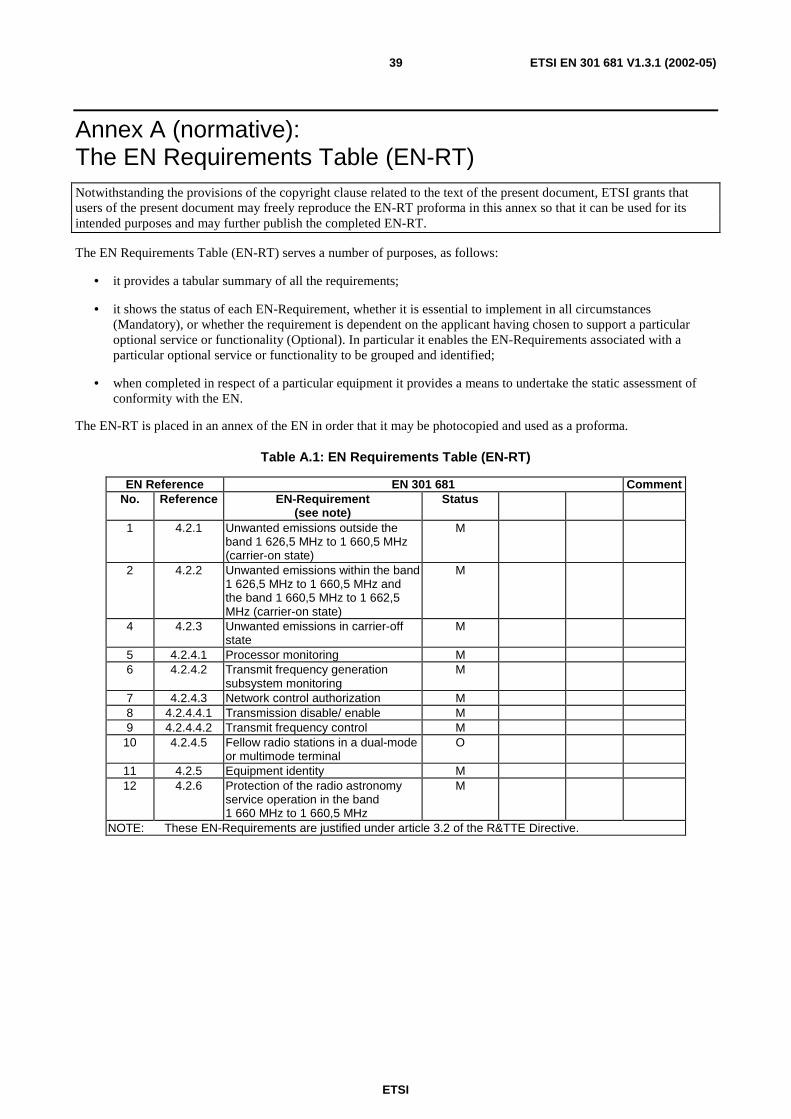
ETSI
ETSI EN 301 681 V1.3.1 (2002-05)39
Annex A (normative): The EN Requirements Table (EN-RT) Notwithstanding the provisions of the copyright clause related to the text of the present document, ETSI grants that users of the present document may freely reproduce the EN-RT proforma in this annex so that it can be used for its intended purposes and may further publish the completed EN-RT.
The EN Requirements Table (EN-RT) serves a number of purposes, as follows:
• it provides a tabular summary of all the requirements;
• it shows the status of each EN-Requirement, whether it is essential to implement in all circumstances (Mandatory), or whether the requirement is dependent on the applicant having chosen to support a particular optional service or functionality (Optional). In particular it enables the EN-Requirements associated with a particular optional service or functionality to be grouped and identified;
• when completed in respect of a particular equipment it provides a means to undertake the static assessment of conformity with the EN.
The EN-RT is placed in an annex of the EN in order that it may be photocopied and used as a proforma.
Table A.1: EN Requirements Table (EN-RT)
EN Reference EN 301 681 Comment No. Reference EN-Requirement
(see note) Status
1 4.2.1 Unwanted emissions outside the band 1 626,5 MHz to 1 660,5 MHz (carrier-on state)
M
2 4.2.2 Unwanted emissions within the band 1 626,5 MHz to 1 660,5 MHz and the band 1 660,5 MHz to 1 662,5 MHz (carrier-on state)
M
4 4.2.3 Unwanted emissions in carrier-off state
M
5 4.2.4.1 Processor monitoring M 6 4.2.4.2 Transmit frequency generation
subsystem monitoring M
7 4.2.4.3 Network control authorization M 8 4.2.4.4.1 Transmission disable/ enable M 9 4.2.4.4.2 Transmit frequency control M
10 4.2.4.5 Fellow radio stations in a dual-mode or multimode terminal
O
11 4.2.5 Equipment identity M 12 4.2.6 Protection of the radio astronomy
service operation in the band 1 660 MHz to 1 660,5 MHz
M
NOTE: These EN-Requirements are justified under article 3.2 of the R&TTE Directive.
ETSI
ETSI EN 301 681 V1.3.1 (2002-05)40
Key to columns:
No Table entry number;
Reference Clause reference number of conformance requirement within the present document;
Status Status of the entry as follows:
M Mandatory, shall be implemented under all circumstances;
O Optional, may be provided, but if provided shall be implemented in accordance with the requirements;
Comments To be completed as required.
ETSI
ETSI EN 301 681 V1.3.1 (2002-05)41
Annex B (informative): Bibliography
• ETSI EN 301 489-20: "Electromagnetic compatibility and Radio spectrum Matters (ERM); ElectroMagnetic Compatibility (EMC) standard. For radio equipment and service; Part 20: Specific conditions for Mobile Earth Stations (MES) used in the Mobile Satellite Services (MSS)".
• EN 55022: "Limits and methods of measurements of radio interferers characteristics of information technology equipment".
• IEC 60068-2-1: "Environmental testing - Part 2: Tests. Tests A: Cold".
• IEC 60068-2-2: "Environmental testing - Part 2: Tests. Tests B: Dry heat".
• IEC 60068-2-64: "Environmental testing - Part 2: Test methods - Test Fh: Vibration, broad-band random (digital control) and guidance".
• Construction of an Anechoic Chamber: Technical Report ZVEI AK-R 90/20.
• ITU-R Recommendation M.1480: "Essential technical requirements of mobile earth stations of geostationary mobile-satellite systems that are implementing the GMPCS-Memorandum of Understanding arrangements in parts of the band 1 - 3 GHz".

ETSI
ETSI EN 301 681 V1.3.1 (2002-05)42
Annex C (informative): The EN title in the official languages
Language EN title Danish Satellitjordstationer og systemer (SES); Harmoniseret EN for mobile jordstationer (MESs) for
geostationære mobile satellit systemer, omfattende håndportable jordstationer, til personlige kommunikationsnetværk via satellit (S-PCN) i 1,5/1,6 GHz båndene under den mobile satellittjeneste (MSS), og som dækker de væsentlige krav i R&TTE direktivets artikel 3.2
Dutch Satelliet grondstations en systemen (SES); Geharmoniseerde EN voor Mobiele grondstations (MESs) van geostationaire mobiele satellietsystemen, inclusief handsets voor Satellite Personal Communications Networks (S-PCN) in the banden 1,5/1,6 GHz als onderdeel van de mobiele satellite dienst (MSS) welke invulling geeft aan de wezenlijke vereisten, neergelegd in artikel 3.2 va de R&TTE Directive
English Satellite Earth Stations and Systems (SES); Harmonized EN for Mobile Earth Stations (MESs) of Geostationary mobile satellite systems, including handheld earth stations, for Satellite Personal Communications Networks (S-PCN) in the 1,5/1,6 GHz bands under the Mobile Satellite Service (MSS) covering essential requirements under article 3.2 of the R&TTE directive
Finnish Satelliittimaa-asemat ja järjestelmät (SES); Yhdenmukaistettu standardi (EN) geostationäärisen satelliittijärjestelmän siirtyvän liikenteen maa-asemille (MES), mukaan lukien kannettavat maa-asemat, henkilökohtaisille satelliittiviestintäverkoille (S-PCN) 1,5/1,6 GHz:n taajuusalueilla siirtyvän liikenteen satelliittijärjestelmissä (MSS), jotka kattavat R&TTE direktiivin artikla 3.2 mukaiset olennaiset vaatimukset
French Stations terriennes et systèmes à Satellites (SES); Norme européenne (EN) harmonisée s'appliquant aux stations terriennes mobiles (MES) des systèmes à satellites géostationnaires pour mobiles, y compris aux stations terriennes portables, destinées aux réseaux de communications personnelles par satellites (S-PCN) fonctionnant dans les bandes de fréquences à 1,5 / 1,6 GHz du Service Mobile par Satellite (SMS), et permettant de satisfaire à l'exigence essentielle de l'article 3.2 de la directive R&TTE
German Satelliten-Erdfunkstellen und -Systeme (SES); Harmonisierte Europäische Norm (EN) für mobile Erdfunkstellen (MES) einschließlich Handfunkgeräte in geostationären mobilen satellitengestützten Funksystemen für private satellitengestützte Kommunikationsnetze (S-PCN) in den Frequenzbändern 1,5/1,6 GHz für den Einsatz im mobilen satellitengestützten Funkdienst (MSS) mit wesentlichen Anforderungen nach R&TTE-Richtlinie Artikel 3.2
Greek ∆ορυφορικοί Επίγειοι Σταθµοί και Συστήµατα (SES) - Εναρµονισµένο ΕΝ που αφορούν Κινητούς Επίγειους Σταθµούς (MESs) συστηµάτων γεωστατικών δορυφόρων κινητών επικοινωνιών, συµπεριλαµβανοµένων των χειρόφερτων επίγειων σταθµών, για ∆ορυφορικά ∆ίκτυα Προσωπικών Επικοινωνιών (S-PCN) στις ζώνες 1,5/1,6 GHz στο πλαίσιο της Κινητής ∆ορυφορικής Υπηρεσίας (MSS) για την κάλυψη των ουσιωδών απαιτήσεων του άρθρου 3.2 της Οδηγίας R&TTE
Italian Stazioni e sistemi satellitari di terra (SES); Norma armonizzata per Stazioni di terra mobili (MES) di sistemi satellitari mobili geostazionari, incluse stazioni di terra palmari, per reti di comunicazione privata satellitare (S-PCN) nelle bande 1,5/1,6GHz nel Servizio Satellitare Mobile (MSS), relativa ai requisiti essenziali dell'articolo 3.2 della direttiva R&TTE.
Portuguese Sistemas e Estações Terrenas de Satélite (SES); EN harmonizada para Estações Terrenas Móveis do sistema móvel de satélites Geoestacionários, incluindo estações portáteis para redes de comunicações pessoais por satélite (S-PCN) nas bandas de 1,5/1,6 GHz do serviço móvel de satélite (MSS), cobrindo os requisitos essenciais no âmbito do Artigo 3.2 da Directiva R&TTE.
Spanish Estaciones Terrenas y Sistemas Satélite (SES); EN armonizada para Estaciones Terrestres Móviles (MESs) de sistemas satélite móviles geoestacionarios, incluidas estaciones terrenas portiles, para Redes de Comunicación Personal por Satélite (S-PCN) en las bandas 1,5/1,6 GHz del Servicio Satélite Móvil (MSS) cubriendo requisitos esenciales según el artículo 3.2 de la directiva de R&TTE
Swedish Sattelitjordstationer och System (SES); Harmoniserad EN för mobila jordstationer (MESs) i geostationära mobilsatellitsystem, omfattande handburna jordstationer för privata satellitkommunikationsnät (S-PCN) i 1,5/1,6 GHz-banden i den mobila satellittjänsten (MSS) omfattande väsentliga krav enligt artikel 3.2 i R&TTE-direktivet
ETSI
ETSI EN 301 681 V1.3.1 (2002-05)43
History
Document history
V1.2.1 January 2000 Publication
V1.3.1 May 2002 Public Enquiry PE 20020906: 2002-05-08 to 2002-09-06