en 13445-4:2002 (e) issue 1 (2002-05) online... · 2009-02-13 · en 13445-4:2002 (e) issue 35...
TRANSCRIPT
EN 13445-4:2002 (E)Issue 1 (2002-05)
3
8.4.4 Impact test ............................................................................................................... .....................................268.4.5 Bend test................................................................................................................. ......................................268.4.6 Macro examination ......................................................................................................... .............................278.4.7 Micro examination ......................................................................................................... ..............................278.4.8 Hardness test ............................................................................................................. ..................................278.4.9 Retests ................................................................................................................... .......................................278.4.10 Test report .............................................................................................................. ......................................28
9 Forming of pressure parts ..................................................................................................... .....................289.1 General..................................................................................................................... .....................................289.2 Ratio of deformation........................................................................................................ ............................289.2.1 Dished circular products .................................................................................................. ..........................289.2.2 Cylinders and cones made by rolling ....................................................................................... .................299.2.3 Other product types....................................................................................................... ..............................309.2.4 Tube bends................................................................................................................ ...................................319.2.5 Forming of Segments....................................................................................................... ...........................329.3 Forming procedures .......................................................................................................... ..........................329.3.1 Cold forming.............................................................................................................. ...................................329.3.2 Hot forming............................................................................................................... ....................................339.4 Heat treatment after forming ................................................................................................ ......................359.4.1 General................................................................................................................... .......................................359.4.2 Heat treatment of flat products after cold forming........................................................................ ...........359.4.3 Heat treatment of tubular products after cold forming..................................................................... .......379.4.4 Heat treatment of clad steels after cold forming .......................................................................... ............379.4.5 Heat treatment after hot forming.......................................................................................... ......................379.4.6 Heat treatment of clad steels after hot forming........................................................................... .............389.5 Sampling of formed test coupons............................................................................................. .................389.5.1 Cold formed products without heat treatment ............................................................................... ..........389.5.2 Hot formed or cold formed products with heat treatment.................................................................... ...389.6 Tests....................................................................................................................... .......................................399.6.1 Base material............................................................................................................. ...................................399.6.2 Butt welds................................................................................................................ .....................................399.6.3 Acceptance criteria for formed test coupons ............................................................................... ............399.6.4 Retests of formed coupons ................................................................................................. .......................399.7 Visual inspection and control of dimension .................................................................................. ...........409.8 Marking ..................................................................................................................... ....................................409.9 Documentation............................................................................................................... ..............................40
10 Post weld heat treatment (PWHT) .............................................................................................. ................4110.1 General.................................................................................................................... ......................................4110.2 Heat treatment conditions .................................................................................................. ........................4110.3 Method of PWHT ............................................................................................................. .............................4410.4 PWHT procedure............................................................................................................. .............................4510.5 Mechanical properties after heat treatment ................................................................................. .............4610.6 Dissimilar ferritic joints ................................................................................................. ..............................4710.7 Special materials.......................................................................................................... ................................47
11 Repairs...................................................................................................................... ....................................4811.1 Repairs of surface defects in the parent metal............................................................................. ............4811.2 Repair of weld defects..................................................................................................... ............................48
12 Finishing operations......................................................................................................... ...........................49
Annex A (informative) Structural tolerances ......................................................................................................... .50
Annex B (informative) Example of a sub-contractors form ..................................................................................54
Annex ZA (informative) Clauses of this European Standard addressing essential requirements or otherprovisions of EU Directives .................................................................................................... ....................55
Bibliography ................................................................................................................... ...........................................56

EN 13445-4:2002 (E) Issue 24 (2006-12)
4
Foreword
This document (EN 13445-4:2002, EN 13445-4:2002/A2:2006 and EN 13445-4:2002/A3:2008) has been prepared by Technical Committee CEN/TC 54 "Unfired pressure vessels", the secretariat of which is held by BSI.
EN 13445-4:2002 shall be given the status of a national standard, either by publication of an identical text or by endorsement, at the latest by November 2002, and conflicting national standards shall be withdrawn at the latest by November 2002. EN 13445-4:2002/A2:2006 shall be given the status of a national standard, either by publication of an identical text or by endorsement, at the latest by June 2007, and conflicting national standards shall be withdrawn at the latest by June 2007. EN 13445-4:2002/A3:2008 shall be given the status of a national standard, either by publication of an identical text or by endorsement, at the latest by June 2009, and conflicting national standards shall be withdrawn at the latest by June 2009.
Attention is drawn to the possibility that some of the elements of this document may be the subject of patent rights. CEN [and/or CENELEC] shall not be held responsible for identifying any or all such patent rights.
This document has been prepared under a mandate given to CEN by the European Commission and the European Free Trade Association, and supports essential requirements of EU Directive(s).
For relationship with EU Directive(s), see informative annex ZA, which is an integral part of this document.
In this standard the Annexes A and B are informative.
This European Standard consists of the following Parts:
Part 1: General.
Part 2: Materials.
Part 3: Design.
Part 4: Fabrication.
Part 5: Inspection and testing.
Part 6: Requirements for the design and fabrication of pressure vessels and pressure parts constructed from spheroidal graphite cast iron.
CR 13445-7, Unfired pressure vessels - Part 7: Guidance on the use of conformity assessment procedures
According to the CEN/CENELEC Internal Regulations, the national standards organizations of the following countries are bound to implement this European Standard: Austria, Belgium, Cyprus, Czech Republic, Denmark, Estonia, Finland, France, Germany, Greece, Hungary, Iceland, Ireland, Italy, Latvia, Lithuania, Luxembourg, Malta, Netherlands, Norway, Poland, Portugal, Romania, Slovakia, Slovenia, Spain, Sweden, Switzerland and the United Kingdom.
EN 13445-4:2002 (E) Issue 35 (2009-01)
5
1 Scope
This document specifies requirements for the manufacture of unfired pressure vessels and their parts, made of steels, including their connections to non-pressure parts. It specifies requirements for material traceability, manufacturing tolerances, welding requirements, production tests, forming requirements, heat treatment, repairs and finishing operations.
2 Normative references
This Europe Standard incorporates by dated or undated reference, provisions from other publications. These normative references are cited at the appropriate places in the text and the publications are listed hereafter. For dated references, subsequent amendments to or revisions of any of these publications apply to this Europe Standard only when incorporated in it by amendment or revision. For undated references the latest edition of the publication referred to applies (including amendments).
EN 287-1:1992, Approval testing of welders — Fusion welding — Part 1: Steels.
EN 729-2:1994, Quality requirements for welding — Fusion welding of metallic materials — Part 2: Comprehensive quality requirements.
EN 729-3:1994, Quality requirements for welding — Fusion welding of metallic materials — Part 3: Standard quality requirements.
EN 875:1995, Destructive tests on welds in metallic materials — Impact tests — Test specimen location, notch orientation and examination.
EN 876:1995, Destructive tests on welds in metallic materials — Longitudinal tensile test on weld metal in fusion welded joints.
EN 895:1995, Destructive tests on welds in metallic materials — Transverse tensile test.
EN 910:1996, Destructive tests on welds in metallic materials — Bend tests.
EN 1043-1:1995, Destructive tests on welds in metallic materials — Hardness testing — Part 1: Hardness test on arc welded joints.
EN 1321:1996, Destructive tests on welds in metallic materials — Macroscopic and microscopic examination of welds.
EN 1418:1997, Welding personnel — Approval testing of welding operators for fusion welding and resistance weld setters for fully mechanized and automatic welding of metallic materials.
EN 10028-2:1992, Flat products made of steels for pressure purposes — Part 2: Non-alloy and alloy steels with specified elevated temperature properties.
EN 10028-3:1992, Flat products made of steels for pressure purposes — Part 3: Weldable fine grain steels, normalized.
EN 10028-4:1994, Flat products made of steels for pressure purposes — Part 4: Nickel alloy steels with specified low temperature properties.
EN 10216-1:2002, Seamless steel tubes for pressure purposes — Technical delivery conditions — Part 1: Non-alloy steel tubes with specified room temperature properties.
EN 13445-4:2002 (E) Issue 35 (2009-01)
6
EN 10216-2:2002, Seamless steel tubes for pressure purposes — Technical delivery conditions — Part 2: Non-alloy and alloy steel tubes with specified elevated temperature properties.
EN 10216-3:2002, Seamless steel tubes for pressure purposes — Technical delivery conditions — Part 3: Alloy fine grain steel tubes.
EN 10216-4:2002, Seamless steel tubes for pressure purposes — Technical delivery conditions — Part 4: Non-alloy and alloy steel tubes with specified low temperature properties.
EN 10217-1:2002, Welded steel tubes for pressure purposes — Technical delivery conditions — Part 1: Non-alloy steel tubes with specified room temperature properties.
EN 10217-2:2002, Welded steel tubes for pressure purposes — Technical delivery conditions — Part 2: Electric welded non-alloy and alloy steel tubes with specified elevated temperature properties.
EN 10217-3:2002, Welded steel tubes for pressure purposes — Technical delivery conditions — Part 3: Alloy fine grain steel tubes.
EN 10217-4:2002, Welded steel tubes for pressure purposes — Technical delivery conditions — Part 4: Electric welded non-alloy and alloy steel tubes with specified low temperature properties.
EN 10217-5:2002, Welded steel tubes for pressure purposes — Technical delivery conditions — Part 5: Submerged arc welded non-alloy and alloy steel tubes with specified elevated temperature properties.
EN 10217-6:2002, Welded steel tubes for pressure purposes — Technical delivery conditions — Part 6: Submerged arc welded non-alloy and alloy steel tubes with specified low temperature properties.
EN 10222-2:2002, Steel forgings for pressure purposes — Part 2: Ferritic and martensitic steels with specified elevated temperature properties.
EN 10222-3:2002, Steel forgings for pressure purposes — Part 3: Nickel steels with specified low temperatures properties.
EN 10222-4:2002, Steel forgings for pressure purposes — Part 4: Weldable fine grain steels with high proof strength.
EN 13445-1:2002, Unfired pressure vessels — Part 1: General.
EN 13445-2:2002, Unfired pressure vessels — Part 2: Materials.
EN 13445-3: 2002 Unfired pressure vessels — Part 3: Design.
EN 13445-5: 2002, Unfired pressure vessels — Part 5: Inspection and testing.
EN 13445-4:2002 (E) Issue 35 (2009-01)
7
EN ISO 15609-1:2004, Specification and qualification of welding procedures for metallic materials — Welding procedure specification — Part 1: Arc welding (ISO 15609-1:2004).
EN ISO 15611:2003, Specification and qualification of welding procedures for metallic materials — Qualification based on previous welding experience (ISO 15611:2003).
EN ISO 15612:2004, Specification and qualification of welding procedures for metallic materials — Qualification by adoption of a standard welding procedure (ISO 15612:2004).
EN ISO 15613:2004, Specification and qualification of welding procedures for metallic materials — Qualification based on pre-production welding test (ISO 15613:2004).
EN ISO 15614-1:2004, Specification and qualification of welding procedures for metallic materials — Welding procedure test — Part 1: Arc and gas welding of steels and arc welding of nickel and nickel alloys (ISO 15614-1:2004).
3 Requirements for manufacturing and subcontracting
3.1 Manufacturing
The general responsibilities of the pressure vessel manufacturer are stated in EN 13445-1:2002. Additionally to those requirements, the manufacturer shall ensure that:
a) the organisation for the control of manufacturing operations which includes special processes such as welding, forming and heat treatment shall be clearly defined by the manufacturer;
b) the manufacturing procedures such as welding, forming and heat treatment are adequate for the purpose and the pressure vessel meets the requirements of this standard. Where specific requirements are associated with materials these shall be taken into account, e.g. EAMs;
c) the manufacturing equipment is adequate for fabrication;
d) the staff is adequate for the assigned tasks;
NOTE As far as welding co-ordination is concerned, the qualifications, tasks and responsibilities can be defined by the manufacturer in accordance with EN 719 [1] in the job assignment.
e) the quality requirements for welding defined in EN 729-3:1994 are met as a minimum.
3.2 Subcontracting
The manufacturer may subcontract work, but shall ensure that the subcontractor carries out the work in accordance with the requirements of this European Standard. The manufacturer is responsible for the adequate definition of the subcontracted task and the need for any associated records.
On all occasions that the subcontractor work includes
a) welding;
b) forming including associated heat treatment;
c) post weld heat treatment;
d) non-destructive testing of welds (see EN 13445-5:2002),
EN 13445-4:2002 (E) Issue 31 (2008-05)
8
the manufacturer shall obtain a subcontractor form (see Annex B).
Where welding operations are subcontracted, the manufacturer shall also either obtain copies of the welding procedure and welding operator qualification records or take other action to ensure that they comply with this standard.
In discharging his responsibility to ensure that the subcontractor carries out the work in accordance with this standard the manufacturer shall ensure that surveillance of the subcontracted work is performed.
Where a manufacturer is producing equipment that requires the intervention of a responsible authority, the manufacturer should inform the responsible authority of his intention to subcontract so that the responsible authority has the opportunity to take part in the subcontractor surveillance.
NOTE 1 See also prEN 764-3:1998, 2.11 [2] and CR 13445-7.
NOTE 2 When the manufacturer is producing equipment based on quality assurance, the controls a manufacturer applies over subcontractors should be described in his approved quality system.
4 Materials
4.1 General
Materials for pressure vessels and the grouping of materials for pressure vessels shall be in accordance with EN 13445-2:2002.
The grouping applies regardless of product form, i.e. plate, forging, piping.
4.2 Material traceability
4.2.1 General
The vessel manufacturer shall have and maintain an identification system for materials used in fabrication, so that all material subject to stress due to pressure and those welded thereto in the completed work can be traced to its origin. This includes the use of welding consumables.
4.2.2 Identification system
4.2.2.1 The vessel manufacturer's identification system shall assure that all materials to be used in the vessel have been subjected to and satisfactorily passed the following:
a) examination of material before fabrication for the purpose of detecting, as far as possible, imperfections which would affect the safety of the work;
b) check of material to determine that it has the required thickness;
c) check of the material to assure that the materials are permitted by this European Standard, fully traceable to the correct material certification and as specified in the design documentation;
d) check of the welding consumables to assure the correct markings and that correct conditions are maintained to prevent deterioration.
EN 13445-4:2002 (E) Issue 35 (2009-01)
17
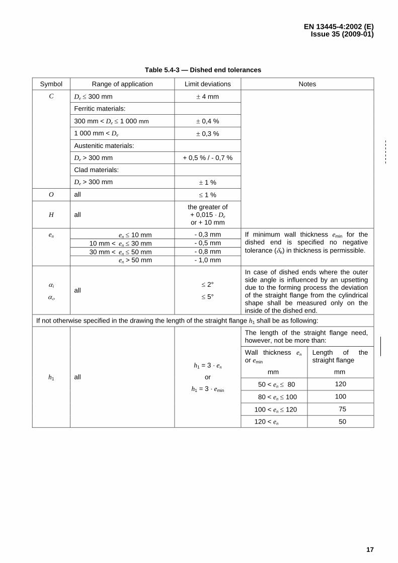
Table 5.4-3 — Dished end tolerances
Symbol Range of application Limit deviations Notes
De ≤ 300 mm ± 4 mm
Ferritic materials:
300 mm < De ≤ 1 000 mm ± 0,4 %
1 000 mm < De ± 0,3 %
Austenitic materials:
De > 300 mm + 0,5 % / - 0,7 %
Clad materials:
C
De > 300 mm ± 1 %
O all ≤ 1 %
H all the greater of + 0,015 · De or + 10 mm
en ≤ 10 mm - 0,3 mm 10 mm < en ≤ 30 mm - 0,5 mm 30 mm < en ≤ 50 mm - 0,8 mm
en
en > 50 mm - 1,0 mm
If minimum wall thickness emin for the dished end is specified no negative tolerance (δe) in thickness is permissible.
αi
αο all
≤ 2°
≤ 5°
In case of dished ends where the outer side angle is influenced by an upsetting due to the forming process the deviation of the straight flange from the cylindrical shape shall be measured only on the inside of the dished end.
If not otherwise specified in the drawing the length of the straight flange h1 shall be as following:
The length of the straight flange need, however, not be more than:
Wall thickness en or emin
mm
Length of the straight flange
mm
50 < en ≤ 80 120
80 < en ≤ 100 100
100 < en ≤ 120 75
h1 all
h1 = 3 · en
or
h1 = 3 · emin
120 < en 50
EN 13445-4:2002 (E) Issue 31 (2008-06)
18
5.5 Tolerances for vessels subjected to external pressure
Tolerances shall be in accordance with EN 13445-3:2002, but in no case shall they exceed the tolerances specified in 5.4.
5.6 Structural tolerances
Structural tolerances, other than those specified in 5.4 and 5.5 should not exceed the values recommended in Annex A.
6 Weld details
6.1 General
The manufacturer in selecting an appropriate weld detail should give consideration to:
a) the method of manufacture;
b) the service conditions (e.g. corrosion);
c) the ability to carry out the necessary non-destructive testing required in accordance with EN 13445-5;
d) the design requirements given in 5.7 and in Annex A of EN 13445-3:2002 for welds.
Other weld details may be used.
NOTE 1 Annex A of EN 13345-3:2002 gives figures of the joints in finished condition, design requirements mainly on geometry, a list of applicable testing groups, recommendations for prevention of lamellar tearing and corrosion.
NOTE 2 Basic weld details are given in EN 1708-1 [5]. These details show sound and commonly accepted practice. It is not intended that these are considered mandatory or should restrict development of welding technology any way and as a result other suitable weld details may be used.
6.2 Vessels or parts made of more than one course
Where a vessel or vessel part is made of two or more courses the longitudinal weld joints of adjacent courses shall be staggered by e⋅4 with 10 mm minimum, or 30 mm minimum when the vessel or vessel part is either working in the creep range or designed by Design by Analysis – Direct Route (Annex B of EN 13445-3:2002) or designed using 6.3 of EN 13445-3:2002.
6.3 Lapped joints, joggle joints, permanent backing strips
Design and weld details shall be in accordance with EN 13445-3.
7 Welding
7.1 General
Welding of the component parts of a pressure vessel shall only be undertaken if the following conditions are satisfied:
a) a welding procedure specification is held by the manufacturer;
b) the welding procedures selected by the manufacturer are qualified for the field of application;
c) the welders and welding operators are qualified for the work allocated to them and their approval is valid.
EN 13445-4:2002 (E) Issue 35 (2009-01)
19
7.2 Welding procedure specification (WPS)
The manufacturer shall compile welding procedure specifications, in accordance with EN ISO 15609-1:2004 for all welds.
7.3 Qualification of welding procedure specifications (WPAR)
Welding procedure specifications to be used in production shall be qualified by reference to an appropriate WPAR.
For the pressure retaining welds of a pressure vessel this shall be achieved by performing welding procedure approval tests in accordance with EN ISO 15614-1:2004 or by preproduction tests in accordance with EN ISO 15613:2004.
In addition to the requirements of EN ISO 15614-1:2004 the following tests shall apply:
a) For test plates on butt joints equal to or over 20 mm thickness a longitudinal weld tensile test having a minimum diameter equal to or over 6 mm shall be performed in accordance with EN 876:1995 and Ret, Rm and A5 shall satisfy the specified minimum requirements of the base material or for weld consumables requirements in EN 13445-2:2002, clause 4.3.5 or other relevant values specifically taken into account in the design (e.g. austenitic filler metal in combination with 9 % Nickel steel).
Where the design temperature is higher than 300 °C then the test shall be done at the design temperature.
NOTE 1 It is important that special consideration is given where the mechanical properties of the weld are below the base materials by design, e.g. 9 % Ni steels welded with austenitic filler metal."
b) a micro examination shall be performed for material groups 8.2 and 10 in accordance with EN 13445-2:2002, Table A-1.
⎯ requirements on welds, material group 8.2: the micro examination shall show adequate microstructure
NOTE 2 Occasional isolated micro fissures with a length of ≤ 1,5 mm may be acceptable, but should be reported.
⎯ requirements on welds, material group 10: the micro examination shall show adequate microstructure
⎯ the ferrite content in the heat affected zone (HAZ) shall be between min. 30 % and max. 70 %. In the high temperature HAZ, a distance of about two times the grain size from the fusion line, the ferrite content shall be equal to or less than 85 %. Where the welding consumable used are of an austenitic-ferritic matching type the ferrite content in the weld metal shall also be between 30 % and 70 %. The ferrite content shall be measured by metallographic methods. If the welding consumables are of non-matching type (i.e. austenitic) the requirement for ferrite content in the weld metal does not apply.
NOTE 3 The limit deviation on metallographic measurements frequently are of the order of ± 5 %.
c) Impact test: The testing and the acceptance criteria shall conform to EN ISO 15614-1:2004; in addition, the impact test requirements in accordance with EN 13445-2:2002, Annex B shall apply.
For austenitic steels see also Clause 8.2 a) 2) of this part of the standard.
For welds other than pressure retaining welds directly attached to the pressure vessels e.g. tray rings, support feet, etc. welding procedure specifications may be acceptable by holding welding procedure approval records carried out in accordance with EN ISO 15611:2003 and EN ISO 15612:2004.
EN 13445-4:2002 (E) Issue 35 (2009-01)
20
If required, the welding procedure approval records shall be approved by a competent third party, who shall perform examination and tests (or have them carried out) as specified in EN ISO 15614-1:2004 and this clause.
NOTE 4 For all test coupons it is permissible for a manufacturer to subcontract preparation of test pieces and their testing but not the welding of the test pieces.
7.4 Qualification of welders and welding operators
Welders and welding operators shall be approved to EN 287-1:1992 or EN 1418:1997 respectively.
NOTE 1 The training, supervision and control of welders and welding operators is the responsibility of the manufacturer.
An up-to-date list of welders and welding operators together with records of their approval test shall be maintained by the manufacturer.
The prolongation (every 6 months) and re-approval (every 2 years) shall be carried out in accordance with EN 287-1:1992.
The evidence in support of the prolongation and re-approval shall be maintained for at least 2 years.
NOTE 2 Any welders not in the employ of the manufacturer may be used provided they are under the full technical control of the manufacturer and work to the manufacturer's requirements.
7.5 Filler metals and auxiliary materials
The technical delivery conditions for welding consumables shall be in accordance with EN 13445-2:2002. The filler metals and auxiliary materials shall be documented, and shall be suitable for use with the parent metals, the welding processes and the fabricating conditions.
All welding consumables shall be stored and handled with care and used in accordance with the conditions specified by the welding consumable manufacturer.
NOTE This is particularly important where baking and drying are specified.
Electrodes, filler wires and rods and fluxes that show signs of damage or deterioration, such as cracked or flaked coating, rusting or dirty electrode wire, shall not be used.
7.6 Joint preparation
Material shall be cut to size and shape by any mechanical or thermal cutting process or by combination of both.
NOTE 1 This may be carried out before or after forming operations.
Where thermal cutting is employed precautions shall be taken to ensure that the edges are not adversely influenced by hardening.
NOTE 2 For some materials this will involve preheating prior to cutting.
The cut edges of ferritic steel which are cut by the thermal process, shall be dressed back by grinding or machining if required by the WPS.
The surface to be welded shall be thoroughly cleaned of oxide, scale, oil grease or other foreign substance and shall be free of defects such as inclusions, cracks and laminations to avoid any detrimental effect on weld quality.
EN 13445-4:2002 (E)Issue 1 (2002-05)
21
The edges to be welded shall be kept in position, either by mechanical means, temporary attachments or by tackwelds or by a combination. The tack welds shall be removed or fused again in the weld bead (see Note 3). In bothcases, the manufacturer shall take all precautions so that the tack welding or temporary attachment or acombination of these does not generate metallurgical or homogeneity defects.
NOTE 3 It is permissible to use tack welds and incorporate them into the final weld provided they have been madeto an approved welding procedure by approved welders.
Where single sided welds are being used, the manufacturer shall ensure that the alignment and the gap of theedges to be welded will be adequate to assure the required penetration at the weld root.
During the whole welding operation, the edges to be welded shall be held so that the alignment tolerances definedin 5.2 are satisfied.
7.7 Execution of welded joints
The welder shall have available the applicable WPS or detailed work instructions based on the approved WPS anddefining all essential variables under direct control by the welder.
Depending on the weld process, after each weld run, the slag shall be removed and the weld cleaned and thesurface defects removed to obtain the proper quality of weld metal.
Unless the welding process used provides effective and sound penetration, the second side of a welded joint shallbe removed back to sound metal using a mechanical or thermal process or by grinding.
Arc strikes on pressure vessel parts outside the weld preparation shall be avoided. Where arc strikes occursaccidentally the affected area (including the heat affected area) shall be repaired in accordance with 11.1.
A record shall be maintained of which welder or welding operator has carried out each weld.
NOTE This may be by marking each weld with a welder identification mark or alternatively by means of records whichassure traceability of the welder to his work throughout the construction of the pressure vessel.
7.8 Attachments, supports and stiffeners
Attachments, whether temporary or not, supports and stiffeners shall be welded to a part subject to pressure byqualified welders using a qualified procedure.
Temporary attachments shall be removed using a technique which does not affect the properties of the metal of thepressure part to which they are welded. Care shall to be taken that the area of the removed attachment is free ofsurface cracks. Repair shall be carried out in a accordance with 11.2.
Cold formed dished ends of ferritic steels without subsequent heat treatment shall not be welded or heated uplocally to temperatures between 550 °C and 750 °C in the knuckle area.
EN 13445-4:2002 (E) Issue 35 (2009-01)
22
7.9 Preheat
The manufacturer shall include in the WPS the preheating temperatures and, where relevant, the inter-pass temperatures required for the welding. The preheating temperature shall be determined by taking into consideration the composition, and thickness of the metal being welded, the welding process being used and the arc parameters.
NOTE Recommendations for preheating for ferritic steels are given in EN 1011-2 [4], recommendations for preheat control are given in EN ISO 13916 [6].
The preheating temperature specified in the WPS shall be adhered to when tack welding and during the entire welding operation. Adherence to the preheating temperature shall be continuously monitored with suitable measuring instruments or temperature indicating crayons.
No welding shall be carried out when the temperature of the parent metal near the joint is less than +5 °C.
8 Manufacture and testing of welds — Production test
8.1 General
In order to control the continuing quality of the manufacture and the compliance of the mechanical properties of the welds with the specification, production test plates shall be welded and tested in accordance with 8.2 and 8.3.
Production test plates apply only to governing shell-longitudinal and –circumferential welds (see EN 13445-3:2002).
Specific requirements apply to vessels and vessel parts made of thermo-mechanically rolled steels (group 2.1) and quenched and tempered steels (group 3.1). See 8.2 f).
NOTE When a vessel includes one or more longitudinal welds the test plates should wherever practicable be attached to the shell plate on one end of the weld so that the edges to be welded in the test plate are a continuation and duplication of the corresponding edges of the longitudinal welds. The weld metal should be deposited in the test plates continuously with the welding of the corresponding longitudinal weld so that the welding process, procedure and technique are the same. When it is necessary to weld the test plates separately, the procedure used should duplicate that used in the construction of the vessel.
Where difficulties are encountered with electro slag welds in transferring from welds with different curvatures (e.g. from a cylinder to a flat coupon plate) the test plate may be welded separately either immediately before or immediately after the welds of the vessel, using the same welding parameters.
When the test plates are required for circumferential welds they shall be welded separately from the vessel providing the technique used in their preparation duplicates as far as possible the procedure used in the welding of the appropriate welds of the vessel.
8.2 Reference criteria
The criteria for the determination the number of production test plates is given below. This is dependent upon the material, the length of welded joints, the thickness, post weld heat treatment (PWHT) and the joint coefficient for each qualified weld procedure. Special provisions are given for testing group 4. The actual testing of production test plates is dependent on the material and the thickness. Additional specific impact testing requirements are also addressed below.
EN 13445-4:2002 (E) Issue 35 (2009-01)
22a
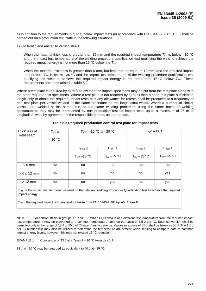
a) In addition to the requirements in c) to f) below impact tests (in accordance with EN 13445-2:2002, B 3.) shall be carried out on a production test plate in the following situations.
1) For ferritic and austenitic-ferritic steels:
⎯ When the material thickness is greater than 12 mm and the required impact temperature TKV is below - 10 °C and the impact test temperature of the welding procedure qualification test qualifying the weld to achieve the required impact energy is not more than 15 °C below the TKV.
⎯ When the material thickness is greater than 6 mm, but less than or equal to 12 mm, and the required impact temperature TKV is below –30 °C and the impact test temperature of the welding procedure qualification test qualifying the weld to achieve the required impact energy is not more than 15 °C below TKV. These requirements are summarised in table 8.2.
Where a test plate is required by c) to f) below then the impact specimens may be cut from the test plate along with the other required test specimens. Where a test plate is not required by c) to e) then a short test plate sufficient in length only to obtain the required impact tests plus any allowance for retests shall be produced at a frequency of one test plate per vessel welded to the same procedure as the longitudinal welds. Where a number of similar vessels are welded at the same time, to the same welding procedure using the same batch of welding consumables, they may be represented by one production test for impact tests up to a maximum of 25 m of longitudinal weld by agreement of the responsible parties, as appropriate.
Table 8.2 Required production control test plate for impact tests
TKV ≥
–10 °C
TKV< –10 °C ≥ –30 °C TKV< –30 °C Thickness of weld seam
TPQR ≤
TKV –15 °C
TPQR >
TKV –15 °C
TPQR ≤
TKV –15 °C
TPQR >
TKV –15 °C
≤ 6 mm no no no no no
> 6 ≤ 12 mm no no no no yes
> 12 mm no no yes no yes
TPQR = the impact test temperature used on the relevant Welding Procedure Qualification test to achieve the required impact energy.
TKV = the required impact test temperature taken from EN 13445-2:2002/prA5, Annex B.
NOTE 1 For carbon steels in groups 1.1 and 1.2: When PQR data is at a different test temperature from the required impact test temperature, it may be converted to a common temperature base on the basis of 1,5 J per °C. Such conversion shall be permitted only in the range of 18 J to 55 J of Charpy V impact energy. Values in excess of 55 J shall be taken as 55 J. The 1,5 J per °C relationship may also be utilised to determine the temperature adjustment when seeking to compare data at common impact energy levels, however, this may not exceed 15 °C reduction.
EXAMPLE 1 Conversion of 33 J at a TPQR of – 20 °C towards 40 J:
33 J at –20 °C may be regarded as equivalent to 40 J at –15 °C.
EN 13445-4:2002 (E) Issue 35 (2009-01)
22b
EXAMPLE 2 Conversion of 100 J at a TPQR of – 20 °C towards 40 J (restriction to max. 55 J):
100 J at –20 °C may be regarded as equivalent to 40 J at –30 °C.
EXAMPLE 3 Conversion of 100 J at a TPQR of – 20 °C towards 27 J (restriction to max. 55 J and reduction of max. 15 °C)
With 100 J at –20 °C one can use an equivalent of 27 J at a temperature not lower than –35 °C.
2. For austenitic steels:
When the minimum design temperature TM of the vessel is less than -105 °C the weld and heat-affected zones shall meet a minimum of 40 J when tested at -196 °C.
NOTE 2 For practical reasons, the test temperature of -196 °C is standardised for all austenitic steel testing of any design temperature below -105 °C.
For filler metals of type 19 9 L, 19 9 Nb, 19 12 3 L, 19 12 3 L Si, 19 13 4 N L, 25 20 L, 25 22 2 N L, 27 31 4 Cu L and nickel based filler metals this may be demonstrated on procedure qualification tests, and further production test plates are not required.
For other weld metal composition and where the weld metal ferrite content exceeds 12 FN, each batch of weld metal shall demonstrate the required impact properties, or a production test plate for impact properties shall be carried out per vessel at -196 °C.
NOTE 3 For filler metal designation see EN ISO 14343.
EN 13445-4:2002 (E) Issue 35 (2009-01)
23
b) For the welds in vessels in testing group 4 (see EN 13445-5:2002) no production test plates shall be required.
c) There is a strict relationship between the WPS and the mechanical properties obtained in the procedure approval test for material group 1.1. Because of the tolerance of material group 1.1 to weld procedural variables, production tests are not required if all the following conditions are met:
1) the quality requirements for welding according to EN 729-2:1994 or EN 729-3:1994 are fulfilled;
2) the welding process is fully mechanised (see ISO 857-1 [3]) ensuring that the welding procedure is applied consistently
3) there is no requirement in the WPS for preheating or post weld heat treatment (PWHT);
4) the wall thickness en ≤ 30 mm.
d) For vessels made of materials in material groups 1.1, 1.2 and 8.1 the following shall apply:
1) for longitudinal welds, one test plate per vessel in the case of joint coefficient 1,0;
2) one test plate per 100 m of longitudinal welds in the case of joint coefficient 0,85;
3) one test plate per year, where the circumferential welds are welded to a procedure involving joggle joints or permanent backing strips (see 6.3).
After 10 consecutive test plates have successfully passed the tests, testing shall be reduced to the following:
4) one test plate per 100 m of longitudinal welds in the case joint coefficient of 1,0;
5) one test plate per 1 000 m of longitudinal welds in the case of joint coefficient 0,85;
6) one test plate per year, where the circumferential welds are welded to a procedure involving joggle joints or permanent backing strips (see 6.3).
e) For vessels made of material in material groups other than those covered in d) independent of the joint coefficient the following shall apply:
1) for longitudinal welds, one test plate per vessel and cast;
2) where the circumferential welds are welded to a procedure different to the longitudinal joints, two test plates per year or one test plate per vessel which ever is less.
After 50 consecutive test plates have successfully past the tests, testing shall be reduced to the following:
3) one test plate per 50 m of longitudinal welds;
4) where the circumferential welds are welded to a procedure different to the longitudinal joints, two test plates per year or one test plate per vessel which ever is less.
EN 13445-4:2002 (E) Issue 24 (2006-12)
24
f) For vessels made of thermo-mechanically rolled steels (group 2.1) and quenched and tempered steels (group 3.1), independent of the weld joint coefficient, the following shall apply:
1) for vessels not subjected to post-weld heat treatment, d) shall apply;
2) for longitudinal welds, made by an automatic welding process, one test plate per vessel, WPS, cast and post-weld heat treatment furnace load;
3) for circumferential welds, made by an automatic welding process, if welded using the same WPS as for longitudinal welds, no further test plates are required. If welded by a different WPS to that used for longitudinal welds, one test plate per vessel, WPS, cast and post-weld heat treatment furnace load;
4) for welds made by manual welding process, one test plate per vessel, WPS, welding position, cast and post-weld heat treatment furnace load;
5) after 10 consecutive test plates have successfully passed the tests, testing shall be reduced to the following:
i) for automatic welded longitudinal welds, one test plate per vessel;
ii) for manual welds, one test plate per vessel in the most difficult welding position.
The testing of the production test plate shall consider the parameters for the post-weld heat treatment(s) of the pressure vessel.
8.3 Extent of testing
The type and number of specimens to be taken from the test plate after final heat treatment shall be in accordance with Table 8.3-1 for the particular material and thickness applicable.
NOTE The number and type of test specimens to be taken from the test plate are dependent on material group and thickness.
The test plate shall be of sufficient size to allow for the required specimens including an allowance for retests.
Prior to cutting the test pieces, the test plate shall be non-destructively tested in order to ensure that the test specimens are taken from sound areas.
EN 13445-4:2002 (E)Issue 1 (2002-05)
25
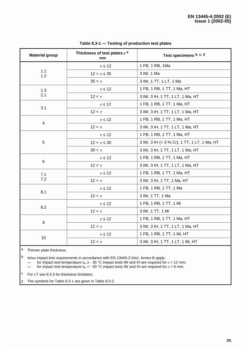
Table 8.3-1 — Testing of production test plates
Material group Thickness of test plates e a
mmTest specimens b, c, d
e ≤ 12 1 FB, 1 RB, 1Ma
12 < e ≤ 35 3 IW, 1 Ma1.11.2
35 < e 3 IW, 1 TT, 1 LT, 1 Ma
e ≤ 12 1 FB, 1 RB, 1 TT, 1 Ma, HT1.32.1 12 < e 3 IW, 3 IH, 1 TT, 1 LT, 1 Ma, HT
e ≤ 12 1 FB, 1 RB, 1 TT, 1 Ma, HT3.1
12 < e 3 IW, 3 IH, 1 TT, 1 LT, 1 Ma, HT
e ≤ 12 1 FB, 1 RB, 1 TT, 1 Ma, HT4
12 < e 3 IW, 3 IH, 1 TT, 1 LT, 1 Ma, HT
e ≤ 12 1 FB, 1 RB, 1 TT, 1 Ma, HT
12 < e ≤ 30 3 IW, 3 IH (> 3 % Cr), 1 TT, 1 LT, 1 Ma, HT5
30 < e 3 IW, 3 IH, 1 TT, 1 LT, 1 Ma, HT
e ≤ 12 1 FB, 1 RB, 1 TT, 1 Ma, HT6
12 < e 3 IW, 3 IH, 1 TT, 1 LT, 1 Ma, HT
e ≤ 12 1 FB, 1 RB, 1 TT, 1 Ma, HT7.17.2 12 < e 3 IW, 3 IH, 1 TT, 1 Ma, HT
e ≤ 12 1 FB, 1 RB, 1 TT, 1 Ma8.1
12 < e 3 IW, 1 TT, 1 Ma
e ≤ 12 1 FB, 1 RB, 1 TT, 1 Mi8.2
12 < e 3 IW, 1 TT, 1 Mi
e ≤ 12 1 FB, 1 RB, 1 TT, 1 Ma, HT9
12 < e 3 IW, 3 IH, 1 TT, 1 LT, 1 Ma, HT
e ≤ 12 1 FB, 1 RB, 1 TT, 1 Mi, HT10
12 < e 3 IW, 3 IH, 1 TT, 1 LT, 1 Mi, HT
a Thinner plate thickness.
b When impact test requirements in accordance with EN 13445-2:2002, Annex B apply:— for impact test temperature tkv ≥ - 30 °C impact tests IW and IH are required for e > 12 mm;— for impact test temperature tkv < - 30 °C impact tests IW and IH are required for e > 6 mm.
c For LT see 8.4.3 for thickness limitation.
d The symbols for Table 8.3-1 are given in Table 8.3-2.
EN 13445-4:2002 (E) Issue 35 (2009-01)
26
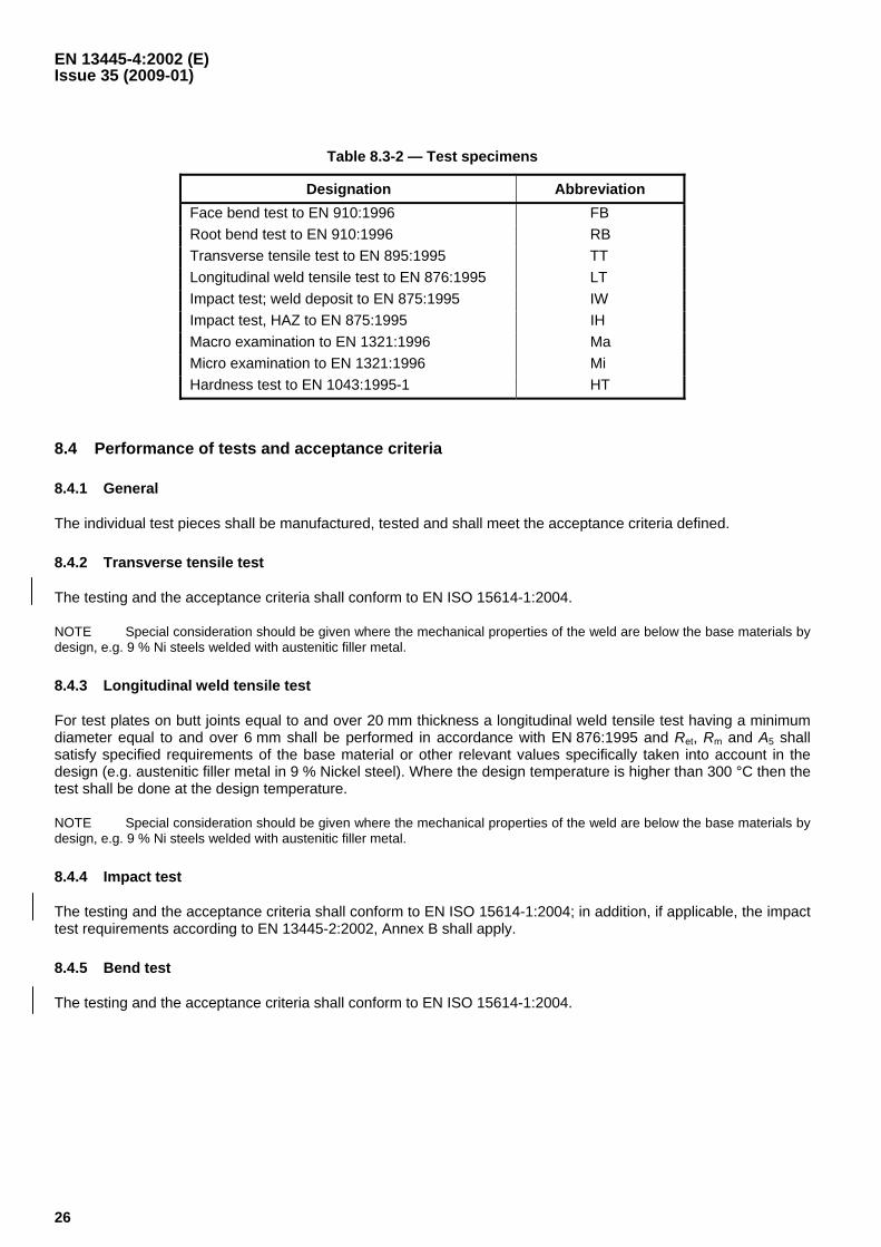
Table 8.3-2 — Test specimens
Designation Abbreviation Face bend test to EN 910:1996 FB Root bend test to EN 910:1996 RB Transverse tensile test to EN 895:1995 TT Longitudinal weld tensile test to EN 876:1995 LT Impact test; weld deposit to EN 875:1995 IW Impact test, HAZ to EN 875:1995 IH Macro examination to EN 1321:1996 Ma Micro examination to EN 1321:1996 Mi Hardness test to EN 1043:1995-1 HT
8.4 Performance of tests and acceptance criteria
8.4.1 General
The individual test pieces shall be manufactured, tested and shall meet the acceptance criteria defined.
8.4.2 Transverse tensile test
The testing and the acceptance criteria shall conform to EN ISO 15614-1:2004.
NOTE Special consideration should be given where the mechanical properties of the weld are below the base materials by design, e.g. 9 % Ni steels welded with austenitic filler metal.
8.4.3 Longitudinal weld tensile test
For test plates on butt joints equal to and over 20 mm thickness a longitudinal weld tensile test having a minimum diameter equal to and over 6 mm shall be performed in accordance with EN 876:1995 and Ret, Rm and A5 shall satisfy specified requirements of the base material or other relevant values specifically taken into account in the design (e.g. austenitic filler metal in 9 % Nickel steel). Where the design temperature is higher than 300 °C then the test shall be done at the design temperature.
NOTE Special consideration should be given where the mechanical properties of the weld are below the base materials by design, e.g. 9 % Ni steels welded with austenitic filler metal.
8.4.4 Impact test
The testing and the acceptance criteria shall conform to EN ISO 15614-1:2004; in addition, if applicable, the impact test requirements according to EN 13445-2:2002, Annex B shall apply.
8.4.5 Bend test
The testing and the acceptance criteria shall conform to EN ISO 15614-1:2004.
EN 13445-4:2002 (E) Issue 35 (2009-01)
27
8.4.6 Macro examination
The testing and the acceptance criteria shall conform to EN ISO 15614-1:2004.
The macro examination shall show sound build-up of beads and sound penetration.
8.4.7 Micro examination
⎯ requirements on welds, material group 8.2: the micro examination shall show adequate microstructure
NOTE Occasional isolated micro fissures with a length of ≤ 1,5 mm may be acceptable, but should be reported.
⎯ requirements on welds, material group 10: the micro examination shall show adequate microstructure
The ferrite content in the heat affected zone (HAZ) shall be between min. 30 % and max. 70 %. In the high temperature HAZ, a distance of about two grain size from the fusion line, a ferrite content shall be equal or less than 85 %. Where the welding consumable used are of an austenitic-ferritic matching type the ferrite content in the weld metal shall also be between 30 % and 70 %. If the welding consumables are of non-matching type (i.e. austenitic) the requirement for ferrite content in the weld metal does not apply.
NOTE The limit deviations on metallographic measurements frequently are of the order of ± 5 %.
8.4.8 Hardness test
The testing and the acceptance criteria shall conform to EN ISO 15614-1:2004.
8.4.9 Retests
Where individual tests do not conform to the requirements specified in this standard and the reasons shall be investigated. Where the unsatisfactory test result is due to poor testing technique or to a locally limited imperfection the following retests shall be made:
a) tensile test: the test shall be repeated on two tensile test specimens taken from the same test plate, both results shall meet the requirements;
b) bend test: the test shall be repeated on two bend test specimens taken from the same test plate; both results shall meet the requirements;
c) impact test: the test shall be repeated on three Charpy-V-notch specimens taken from the same test plate;
1) the mean value obtained from all six individual specimens shall be equal to or greater than the specified minimum value;
2) not more than two of the six individual values shall be less than the specified minimum value;
3) not more than one of the six individual values shall be less than 70 % of the specified minimum value.
Should any of the retests fail to comply with the requirements then the joints/vessels represented by the test plate shall be deemed not in compliance with this Part of this European Standard.
NOTE Production factors may result in a scatter of mechanical test results which may occasionally fall below the agreed specification level.
EN 13445-4:2002 (E)Issue 1 (2002-05)
28
8.4.10 Test report
A test report shall be prepared indicating compliance of the test results and the as found values meeting thespecified requirements.
9 Forming of pressure parts
9.1 General
Manufacturers of formed pressure parts shall maintain records of the forming procedure and the subsequent heattreatment.
NOTE Formed pressure parts can be cold or hot formed. Formed pressure parts can comprise dished ends, segments,cylinders and other formed parts. Formed pressure parts may consist of individual parts which are welded together and formedsubsequently.
9.2 Ratio of deformation
9.2.1 Dished circular products
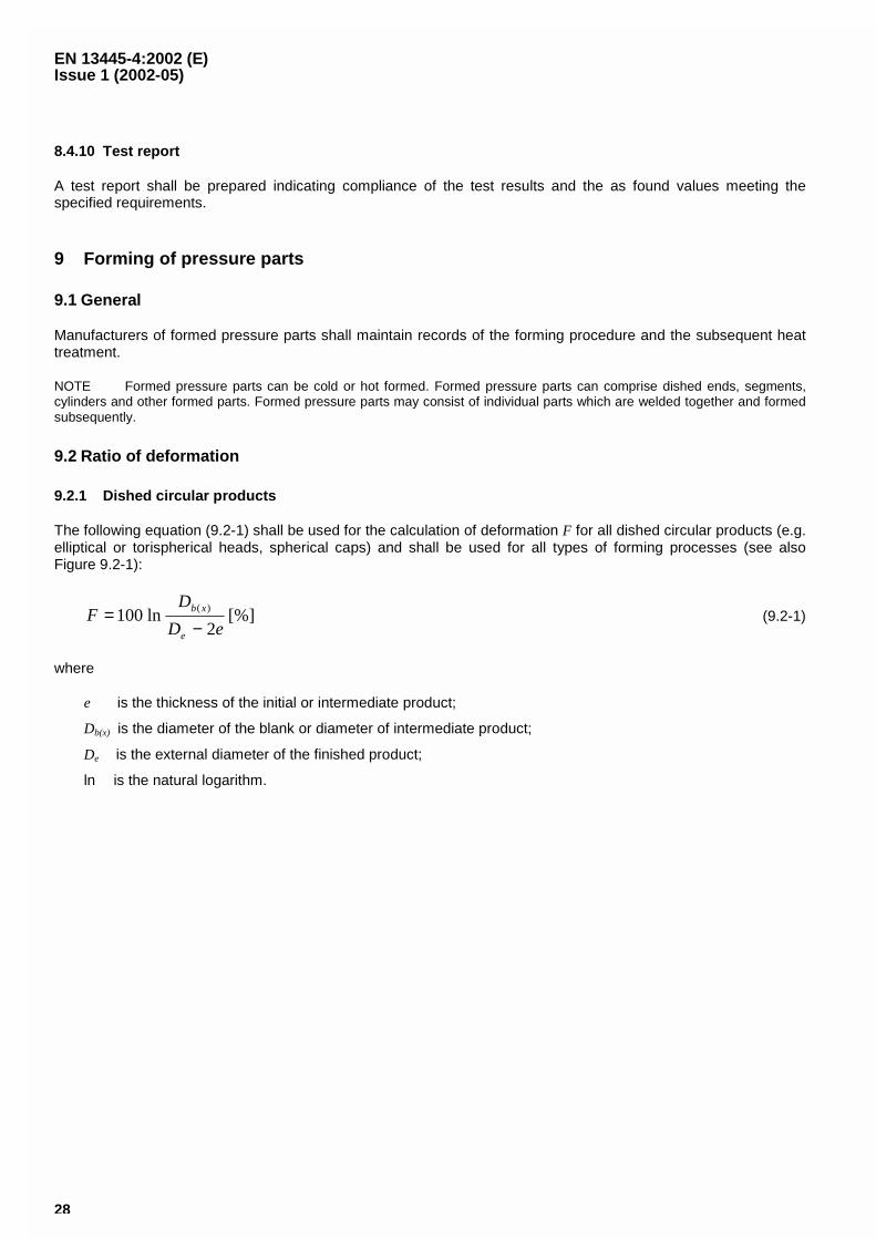
The following equation (9.2-1) shall be used for the calculation of deformation F for all dished circular products (e.g.elliptical or torispherical heads, spherical caps) and shall be used for all types of forming processes (see alsoFigure 9.2-1):
[%]2
ln100 )(
eD
DF
e
xb
−= (9.2-1)
where
e is the thickness of the initial or intermediate product;
Db(x) is the diameter of the blank or diameter of intermediate product;
De is the external diameter of the finished product;
ln is the natural logarithm.
EN 13445-4:2002 (E)Issue 1 (2002-05)
33
9.3.2 Hot forming
9.3.2.1 General
Hot forming of material group 1.1, 1.2, 1.3, 3.1, 4, 5, 6 and 9 shall be carried out at temperatures above themaximum permissible temperature for stress relieving, usually in the temperature range of normalising, inaccordance with the material specifications.
Hot forming of thermo-mechanically treated steel grades is not permitted.
Hot forming of material group 8.1, 8.2 and 10 shall be carried out at a temperature of 300 °C or above usually in thetemperature range according to Table 9.3-1.
For other types of materials the hot forming temperatures shall be in accordance with appropriate EuropeanStandards, data sheets or other specifications.
The forming procedure shall define the rate of heating, the holding temperature and the holding time given to theformed part.
NOTE 1 Hot forming is a process which is performed at temperatures above the stress relief temperature and will usually becarried out in the austenite region.
In view of danger of excessive grain growth, the product shall be austenitised above Ac3, but not higher than1 050 °C.
NOTE 2 After reaching the temperature in the product it should be kept at temperature not longer than 10 min. For the samereason, the heating rate should be defined.
After the hot forming the product shall be cooled in still air, unless otherwise specified in Table 9.3-1.
As every heat treatment above the normalising temperature leads to a grain growth which adversely affects theimpact values, the hot forming for normalised steels shall be divided into two groups as per 9.3.2.2 and 9.3.2.3.
9.3.2.2 Normalised steels with specified impact values at temperatures above and including - 20 °C
For normalised steels which are hot formed only in a single operation the maximum temperature of the productshall not be above 980 °C.
For hot forming operations in more than a single operation the maximum temperature of the product shall not beabove 1 050 °C. Before the last operation the product shall be cooled down below 500 °C. For the last operationthe maximum temperature of the product shall be below 980 °C for steels with a minimum yield strength≤ 360 N/mm2, or 940 °C for steels with a minimum yield strength > 360 N/mm2.
A subsequent heat treatment may be waived, if the forming process of the last operation has been completed at atemperature above 750 °C or above 700 °C where the degree of deformation does not exceed 5 %.
If the conditions of 9.3.2.2, especially regarding the maximum and minimum temperatures in the last operation cannot be achieved, normalising as specified by the steel manufacturer shall be carried out after the forming process.
NOTE For steels which have to be tempered after normalising, the prescribed tempering treatment may be performedwhen the hot forming has been carried out according to 9.3.2.2.
EN 13445-4:2002 (E) Issue 35 (2009-01)
34
9.3.2.3 Normalised steels with specified impact values at temperatures below - 20 °C
For normalised steels which are hot formed only in a single operation the maximum temperature of the product shall not be above 940 °C when the steels with minimum yield strength ≤ 360 N/mm2, or 925 °C for steels with a minimum yield strength > 360 N/mm2.
For hot forming operations in more than a single operation the maximum temperature of the product shall not be above 1 050 °C. Between the different operations the product shall be cooled down below 500 °C. For the last operation the maximum temperature of the product shall be below 940 °C for steels with a minimum yield strength ≤ 360 N/mm2, or 925 °C for steels with a minimum yield strength > 360 N/mm2.
A subsequent heat treatment may be waived, if the forming process of the last operation has been completed at a temperature above 750 °C, or above 700 °C if the degree of deformation does not exceed 2 %.
If the conditions of 9.3.2.3, especially regarding the maximum and minimum temperatures in the last operation can not be achieved, normalising as specified by the steel manufacturer shall be carried out after the hot forming process.
NOTE For steels which have to be tempered after the normalising, the prescribed tempering treatment may be performed when the hot forming has been carried out according to 9.3.2.3.
9.3.2.4 Quenched and tempered steels
For quenched and tempered steels, it is absolutely necessary to perform a total new quenching plus tempering operation after hot forming. For the hot forming process itself, the conditions specified in 9.3.2.1 and 9.3.2.2 shall apply.
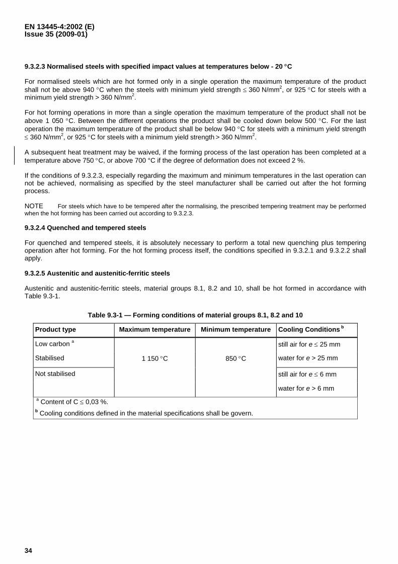
9.3.2.5 Austenitic and austenitic-ferritic steels
Austenitic and austenitic-ferritic steels, material groups 8.1, 8.2 and 10, shall be hot formed in accordance with Table 9.3-1.
Table 9.3-1 — Forming conditions of material groups 8.1, 8.2 and 10
Product type Maximum temperature Minimum temperature Cooling Conditions b
Low carbon a still air for e ≤ 25 mm
Stabilised 1 150 °C 850 °C water for e > 25 mm
Not stabilised still air for e ≤ 6 mm
water for e > 6 mm a Content of C ≤ 0,03 %. b Cooling conditions defined in the material specifications shall be govern.
EN 13445-4:2002 (E) Issue 11 (2004-06)
37
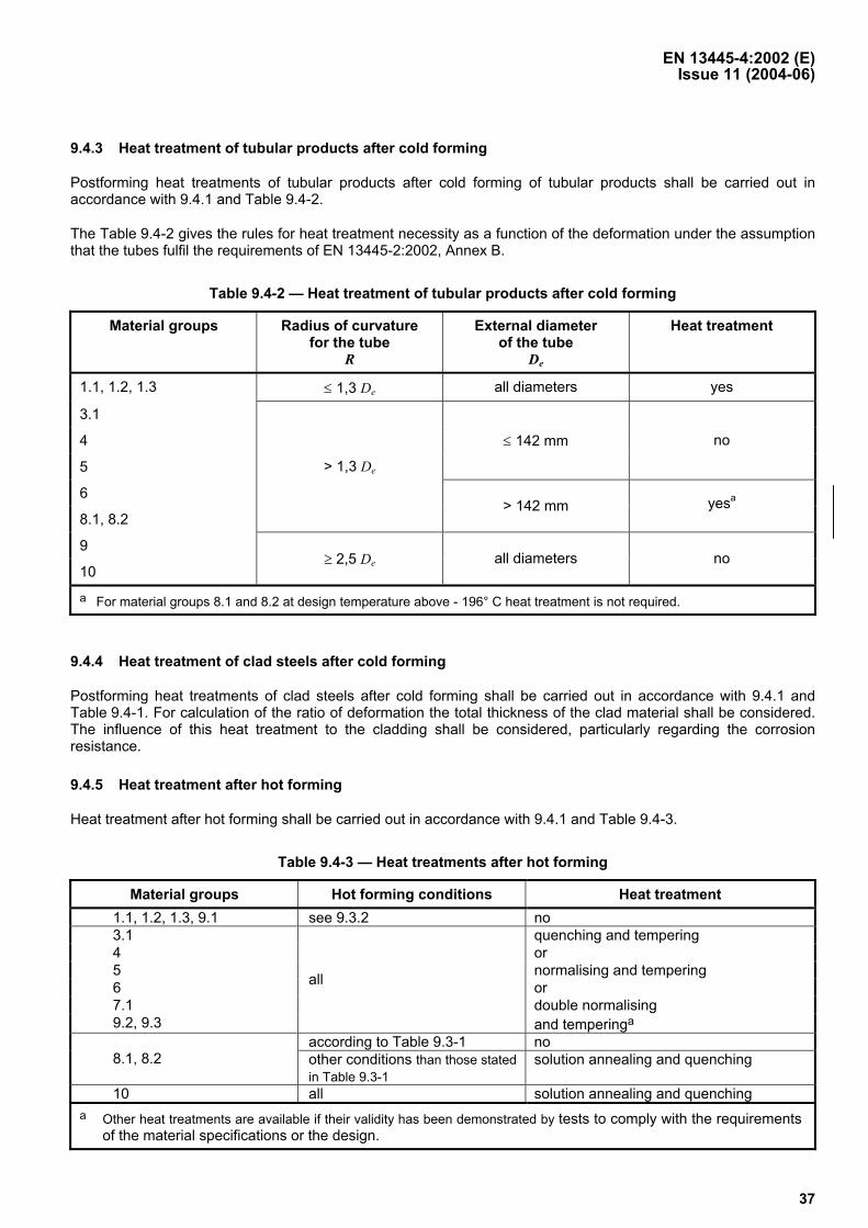
9.4.3 Heat treatment of tubular products after cold forming
Postforming heat treatments of tubular products after cold forming of tubular products shall be carried out in accordance with 9.4.1 and Table 9.4-2.
The Table 9.4-2 gives the rules for heat treatment necessity as a function of the deformation under the assumption that the tubes fulfil the requirements of EN 13445-2:2002, Annex B.
Table 9.4-2 — Heat treatment of tubular products after cold forming
Material groups Radius of curvature for the tube
R
External diameter of the tube
De
Heat treatment
1.1, 1.2, 1.3 ≤ 1,3 De all diameters yes
3.1
4
5
≤ 142 mm no
6
8.1, 8.2
> 1,3 De
> 142 mm yesa
9
10 ≥ 2,5 De all diameters no
a For material groups 8.1 and 8.2 at design temperature above - 196° C heat treatment is not required.
9.4.4 Heat treatment of clad steels after cold forming
Postforming heat treatments of clad steels after cold forming shall be carried out in accordance with 9.4.1 and Table 9.4-1. For calculation of the ratio of deformation the total thickness of the clad material shall be considered. The influence of this heat treatment to the cladding shall be considered, particularly regarding the corrosion resistance.
9.4.5 Heat treatment after hot forming
Heat treatment after hot forming shall be carried out in accordance with 9.4.1 and Table 9.4-3.
Table 9.4-3 — Heat treatments after hot forming
Material groups Hot forming conditions Heat treatment 1.1, 1.2, 1.3, 9.1 see 9.3.2 no 3.1 quenching and tempering 4 or 5 normalising and tempering 6 or 7.1 double normalising 9.2, 9.3
all
and temperinga according to Table 9.3-1 no
8.1, 8.2 other conditions than those stated in Table 9.3-1
solution annealing and quenching
10 all solution annealing and quenching a Other heat treatments are available if their validity has been demonstrated by tests to comply with the requirements
of the material specifications or the design.
EN 13445-4:2002 (E) Issue 35 (2009-01)
38
9.4.6 Heat treatment of clad steels after hot forming
The conditions for heat treatment of clad steels after hot forming shall be carried out in accordance with Table 9.4-3 based on the material backing steel. The influence of this heat treatment on the cladding shall be considered, particularly regarding the corrosion resistance.
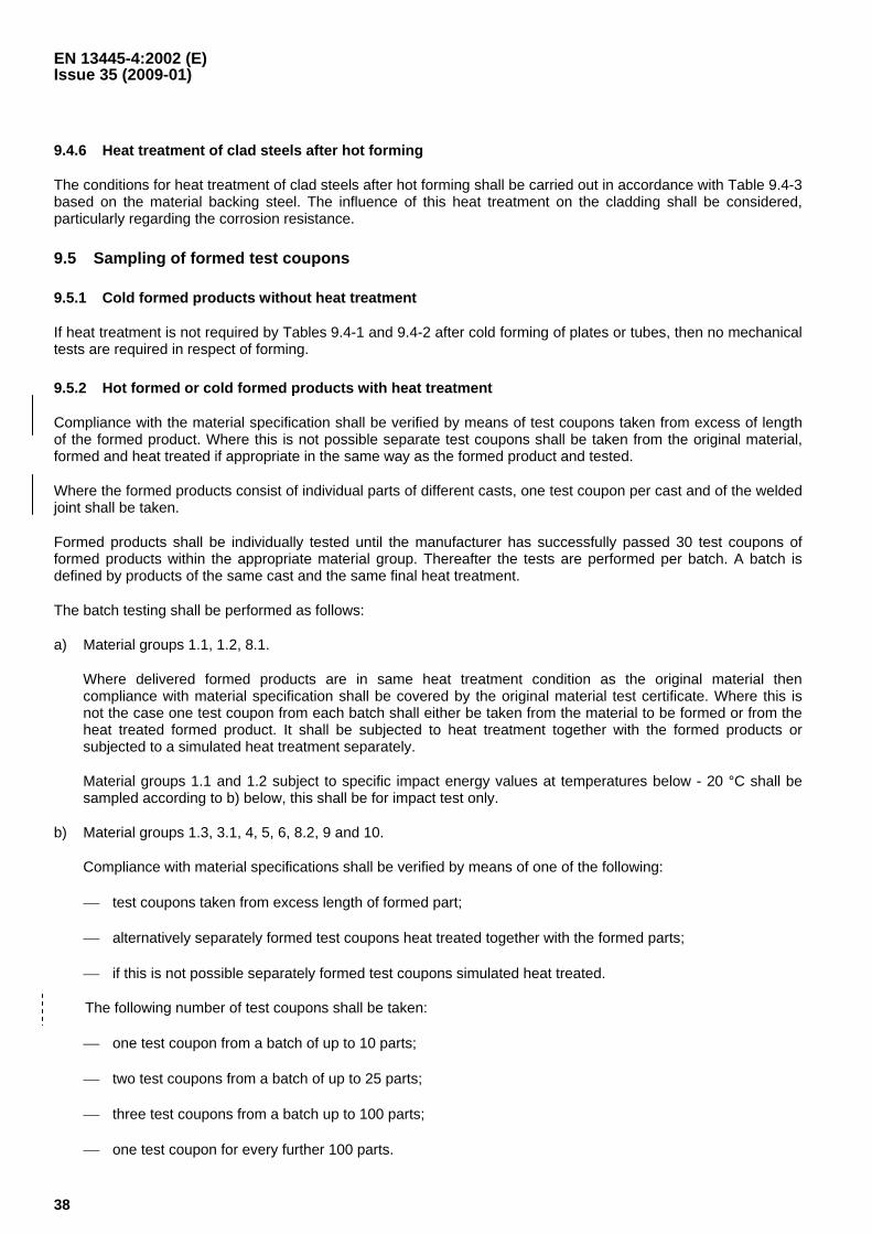
9.5 Sampling of formed test coupons
9.5.1 Cold formed products without heat treatment
If heat treatment is not required by Tables 9.4-1 and 9.4-2 after cold forming of plates or tubes, then no mechanical tests are required in respect of forming.
9.5.2 Hot formed or cold formed products with heat treatment
Compliance with the material specification shall be verified by means of test coupons taken from excess of length of the formed product. Where this is not possible separate test coupons shall be taken from the original material, formed and heat treated if appropriate in the same way as the formed product and tested.
Where the formed products consist of individual parts of different casts, one test coupon per cast and of the welded joint shall be taken.
Formed products shall be individually tested until the manufacturer has successfully passed 30 test coupons of formed products within the appropriate material group. Thereafter the tests are performed per batch. A batch is defined by products of the same cast and the same final heat treatment.
The batch testing shall be performed as follows:
a) Material groups 1.1, 1.2, 8.1.
Where delivered formed products are in same heat treatment condition as the original material then compliance with material specification shall be covered by the original material test certificate. Where this is not the case one test coupon from each batch shall either be taken from the material to be formed or from the heat treated formed product. It shall be subjected to heat treatment together with the formed products or subjected to a simulated heat treatment separately.
Material groups 1.1 and 1.2 subject to specific impact energy values at temperatures below - 20 °C shall be sampled according to b) below, this shall be for impact test only.
b) Material groups 1.3, 3.1, 4, 5, 6, 8.2, 9 and 10.
Compliance with material specifications shall be verified by means of one of the following:
⎯ test coupons taken from excess length of formed part;
⎯ alternatively separately formed test coupons heat treated together with the formed parts;
⎯ if this is not possible separately formed test coupons simulated heat treated.
The following number of test coupons shall be taken:
⎯ one test coupon from a batch of up to 10 parts;
⎯ two test coupons from a batch of up to 25 parts;
⎯ three test coupons from a batch up to 100 parts;
⎯ one test coupon for every further 100 parts.
EN 13445-4:2002 (E) Issue 35 (2009-01)
39
9.6 Tests
9.6.1 Base material
One tensile test and three impact test specimens shall be taken from each test coupon required in 9.5.2. The test specimens shall be taken transverse to the rolling direction with a deviation not greater than 20°.
NOTE For structural mild steels of material group 1.1 and 1.2 the impact test specimens may be taken longitudinal to the rolling direction.
In the case of pressure parts made of quenched and tempered steels with batch testing, 10 % of the formed parts, but not less than 3 formed parts, in addition shall be subjected to hardness testing by the manufacturer.
9.6.2 Butt welds
Where formed products are welded together from several individual parts before forming, the production test shall be performed in accordance with the frequency described in Clause 8.
9.6.3 Acceptance criteria for formed test coupons
For base material the test specimens required in 9.6.1 shall meet the requirements of base materials.
For butt welds the test specimens required in 9.6.2 shall meet the requirements of Clause 8.
The hardness values shall have a variation of not more than 50 HV 10 within one formed part.
9.6.4 Retests of formed coupons
9.6.4.1
If the test results fail to comply with the requirements, the following shall apply:
a) where the unsatisfactory test result is due to poor testing technique or to a locally limited defect of a single specimen, the test result may be neglected and the individual test shall be repeated;
b) where the unsatisfactory test result is due to inadequate heat treatment, all parts of the batch and relevant test coupons shall be heat treated again and the full extent of testing shall be repeated.
EN 13445-4:2002 (E)Issue 6 (2003-04)
40
9.6.4.2
Where the results obtained from test specimens which where correctly taken and tested do not comply with therequirements, the following retests shall be made:
a) tensile test: the test shall be repeated on two tensile test specimens taken from the same test plate; bothresults shall meet the requirements;
b) bend test: the test shall be repeated on two bend test specimens taken from the same test plate; both resultsshall meet the requirements;
c) impact test: the test shall be repeated on three Charpy-V-notch specimens taken from the same test plate;
1) the mean value obtained from all six individual specimens shall be equal to or greater than the specifiedminimum value;
2) not more than two of the six individual values shall be less than the specified minimum value;
3) not more than one of the six individual values shall be less than 70 % of the specified minimum value.
In case of batch testing where the test results failed to comply with the specification. The testing shall be repeatedon two other formed parts of the same batch where the test results shall comply with the specification.
Should any of the retests fail to comply with the requirements then the joints/parts represented by the test plateshall be deemed not in compliance with this Part of this standard.
9.7 Visual inspection and control of dimension
Formed pressure parts shall be subject to visual examination and dimensional check in the delivery condition bythe producer of the formed product. The results of the visual inspection and the dimensional check shall bedocumented.
9.8 Marking
Formed products which form part of a pressure vessel shall be marked according to the relevant materialspecification. In this case the mark of the base material manufacturer may be waived. Traceability to the basematerial shall be ensured. In addition, the mark of the producer of the formed product shall be added. In the case ofbatch testing the relationship to the batch shall be evident. Identification shall be maintained between the testcoupon and the formed product from which they were taken.
For small formed products (less than 220 mm nominal size) marking according to 4.2.2.2 b) is permissible.
9.9 Documentation
Formed products which form part of a pressure vessel require the following documentation:
a) a sub-contractor form (when forming is not carried out by pressure vessel manufacturer);
b) the original material certification;
c) type and record of heat treatment, if applicable;
d) formed product test coupon results, if applicable;
e) description of the formed part with main nominal dimensions and extent of deformation in the case of coldforming without heat treatment;
f) markings.