uk rules for unfired esselsthe first edition of en 13445 is not as comprehensive as bs 5500, and due...
TRANSCRIPT

1
CHAPTER
51 UK RULES FOR UNFIRED PRESSURE
VESSELS David H. Nash

2
51.1 INTRODUCTION
The present code PD 5500, formerly BS 5500 [1] evolved partly from the well-known BS 1500 [2] in the 1950�s and BS
1515 [3] first published in 1965; the latter permitted higher level allowable stresses and more advanced rules. In 1969,
following a report from the Committee of Enquiry into the Pressure Vessel Industry, the British Standards Institution
brought all the pressure vessel interests together under one general committee in order to rationalise the activity. This
became PVE/ and presides over a large committee structure. There are a series of functional sub-committees who deal with
specific aspects and a large number of technical committees as well as many additional sub committees and working groups.
Most of these meet regularly. The technical committee PVE/1, Pressure Vessels, has overall responsibility for BS 5500. The
functional committee PVE/1/15 Design Methods has an overall responsibility relating to �Design� with particular reference
to the design section of BS 5500 (Section 3).
The first edition of BS 5500 was issued in 1976. The actual issue was delayed for some time because, in the early 1970�s,
there was an attempt in Europe to produce an international pressure vessel standard. A draft of the international standard
appeared as ISO DIS 2694 [4] in 1973 but it was not generally accepted and the attempt was abandoned in the mid 70�s. It
was decided to use some of the material from 2694 within BS 5500 so that although the Standard was long delayed it
benefited to some extent from the international efforts. Initially, committee PVE/l set out the concept of a �master� pressure
vessel standard which could readily be applied to any vessel in either ferrous or non-ferrous materials and for highly
specialised application with the minimum of supplementary requirements. The layout of BS 5500 is consistent with this
concept and although the Standard has perhaps not fulfilled this high ideal, it has certainly been employed widely in many
industries including non pressure vessel type applications. When issued it had a number of distinctive features compared
with other pressure codes viz; weld joint factors were removed, the present three categories of construction were introduced,
there was a new novel external pressure section, it has a loose leaf format and an annual updating was introduced. Further
editions of BS 5500 have been issued every three years since 1982.
51.1.1 Withdrawal of BS 5500 and Issue of PD 5500
In May 2002 the first issue of the European Standard EN 13445 Unfired Pressure Vessels [5] was published. This standard
has been developed to facilitate the provision of vessels subject to the European pressure equipment directive 97.23.EC [6]
commonly known as the �PED�. Under the CEN rules BSI was obliged to withdraw BS 5500 when the European Standard
was published in 2002.
The first edition of EN 13445 is not as comprehensive as BS 5500, and due to demands from industry it was decided that the
British pressure vessel standard should continue to be available and become a published document (PD) under the new
reference PD 5500, with equal content, validity and application to the previous BS 5500. Its principle difference is that it
does not have the status of a "national standard".
It should be noted that most other European pressure vessel codes are not national standards (i.e. they are not published by
the national standards body of the country in which they apply).
51.1.2 The Pressure Equipment Directive and PD5500
The main provisions of the Pressure Equipment Directive (PED) are summarised, and are covered in detail in Chapter 47
The Pressure Equipment Directive, 97/23/EC, is what is termed a �new approach� directive which prescribes Essential
Safety Requirements (ESRs) which are intended to maintain existing safety levels within the European Community.
The European Parliament and the Council of Ministers approved the PED in May 1997. All member states were required to
introduce national laws and provisions necessary to comply with the PED by 29 November 1999. A transition period applied
through to 29 May 2002 when the Directive became fully enforced. With its advent, member states must not permit the
placing on the market of pressure equipment or assemblies that do not comply with the regulations in force.
To implement the requirements of the PED in the UK the Department of Trade and Industry (DTI) published the Pressure
Equipment Regulations 1999 (SI 1999/2001) [7], which became law in February 2000. The DTI have also produced a free
guidance booklet URN 99/1147. The Health & Safety Executive is responsible for the enforcement of the legislation in the
UK.
Deleted: UK Rules for Unfired
Pressure Vessels
Deleted: XXX
Deleted: (editor - please add in
correct chapter number here)

3
The Pressure Systems and Transportable Gas Container Regulations 1989, have been revoked and are replaced by the
Pressure Systems Safety Regulations 2000 (SI 2000/128), which apply to the design and construction of pressure equipment
not covered by the Pressure Equipment Regulations, and also to the use and ongoing integrity of pressure systems.
The PED applies to products which are first placed on the market / put into service / supplied in any EU member state, and
applies to equipment produced for the home market as well as for products destined for use in other EU countries. It also
applies to products imported from outside the EU.
The PED covers the design, manufacture and conformity assessment of pressure equipment and assemblies with a maximum
allowable pressure greater than 0.5 barg. The PED does not apply to modifications, servicing and repair of equipment
unless there is a substantial change of use.
Pressure Equipment means:
Pressure vessels � housings designed and built to contain fluids under pressure.
Piping � piping components intended for the transport of fluids when connected together for integration into a
pressure system.
Safety accessories � devices designed to protect pressure equipment against the allowable limits being exceeded.
Pressure accessories � devices with an operational function and having pressure bearing housings.
In general, the duties fall on the manufacturer, but care is needed in determining who the manufacturer is - it is not
necessarily the fabricator. Duties may also fall to a designer, an importer, a user, a supplier, or the manufacturer's authorised
representative.
Each item of equipment is classified into one of the four conformity assessment categories I to IV according to the tables in
Annex II of the PED, or as �sound engineering practice� (SEP) for very low risk equipment. The classification depends on
the type of equipment (vessel, steam generator, or piping), the state of the fluid contents (gas or liquid), the fluid group of
the intended contents (group 1 or 2) and the pressure/volume of the equipment.
Fluid Group 1 comprises those fluids classified, according to the EC Directive on the classification of dangerous substances
(Directive 67/548/EEC of 27 June 1967), as explosive, extremely flammable, highly flammable, flammable, very toxic, toxic
or oxidising. Group 2 comprises all other fluids including steam.
The pressure/volume of the equipment is the design pressure in bars multiplied by the volume in litres, or for piping, the
pressure multiplied by the nominal size in mm.
Equipment classified as (SEP) must be designed and manufactured according to �sound engineering practice�. CE marking
must not be affixed to SEP equipment.
For equipment classified in Categories I to IV, the technical requirements of the PED are presented as a set of basic
principles, the Essential Safety Requirements (ESRs), which have to be met. Article 3 and Annex I of the PED state the
Technical Requirements and the ESRs respectively.
The ESRs cover general requirements, design, manufacturing and materials. The use of the European harmonised standards
being developed, such as EN 13445 on unfired pressure vessels, confers a presumption of conformity to the ESRs. PD 5500
Annex Z gives guidance on the application of PD 5500 to pressure vessels falling within the scope of the PED.
To demonstrate that the essential safety requirements are satisfied, the PED requires equipment to be subjected to
conformity assessment procedures. The conformity assessment modules have been designed to reflect current industrial
practice, and manufacturers are given a choice of modules depending on the category.
Equipment in Category I is subject to the manufacturer's own internal production control. The modules for products in
Categories II, III and IV require the involvement of �notified bodies� appointed by Member States either in the approval and
monitoring of the manufacturers' quality assurance system or in direct product inspection.
Materials used in the construction of equipment which falls within the scope of the PED must comply with the directive.
For equipment which falls within the scope of the PED the materials must comply with the directive.
Three routes are available to demonstrate conformity with the Directive:
- by using materials which comply with harmonised European standards
- by using materials covered by a European Approval of Materials (EAM)
4
- by a Particular Material Appraisal (PMA)
The EAM approval will be performed by those notified bodies specifically appointed for this task. The result of an EAM is a
European Data Sheet, which will contain all the necessary information for the design engineer as well as the inspector.
Reference to the EAM will be published in the Official Journal of the European Communities.
A Particular Material Appraisal follows a similar assessment route without subsequent publication of the information.
Materials approved by this route can only be used by the manufacturer who obtained the approval on the job concerned. If
the same material is used on another job, or by a different manufacturer then a new approval must be obtained.
Some European materials standards have been published, such as EN 10028 Flat products made of steels for pressure
purposes, and EN 10222 Steel forgings for pressure purposes, but many of the materials are not yet readily available from
stock. European material standards for pipe, tube and fittings have not yet been published. In many cases it will be necessary
to follow the EAM or PMA routes where harmonised product or material standards are not yet available, or when the
manufacturer wishes to use materials to BS, ASTM, DIN or other standards.
At present only fifteen EAM approvals have been issued, all relating to Nickel 201 and nickel alloy materials. The PMA
route must be used for all other non-European materials.
The PED, Annex I sub-section 7.1.2 gives specific requirements for the evaluation of allowable stresses. In some cases these
requirements are more conservative than PD 5500 resulting in lower design stresses. In particular, the allowable stress for
ferritic materials is limited to the smaller of Re/1.5 or Rm/2.4 (see where Re is the yield strength and Rm is the ultimate tensile
strength). The safety factor of 2.4 for the tensile strength is slightly higher than the value of 2.35 used to derive the design
strengths for ferritic materials in PD 5500 Tables K.1-2 to K.1-12. For equipment which must comply with the PED the
design strength at ambient temperature may need to be reduced accordingly. For example, the design strength to the PED for
BS 1501-224-490A or 490B material at 50°C would be 204.17 N/mm2 compared with 208.0 N/mm2 from PD 5500 Table
K.1-2.
Similarly, the allowable stress to the PED for austenitic stainless steels where the elongation after rupture exceeds 35%, is
limited to the smaller of Re/1.2 or Rm/t/3.0. In general this only affects the S61 and S63 grades. Rm/t is the tensile strength at
the design temperature. This data is not generally available for BS materials, but for ASME/ASTM materials values are
given in ASME II, Part D, Table U. For example, the design strength to the PED for BS 1501-304-S61 material at 50°C
would be 183.33 N/mm2 compared with 203.0 N/mm2 from PD 5500 Table K.1-4.
For equipment manufactured from carbon steel which must comply with the PED, the factor for Rm should be increased from
2.35 to 2.4. For equipment manufacturer from austenitic stainless steel which must comply with the PED, the factor for Rm
for austenitic stainless steels where the elongation after rupture exceeds 35%, should be increased from 2.5 to 3.0. In the
PED Rm should strictly be Rm/t (the tensile strength at the design temperature), but this data is often not available. Most
austenitic plate materials to BS 1501 Part 3 or ASTM A-240 have a specified elongation which exceeds 35%.
For austenitic stainless steels where the elongation after rupture exceeds 30% but does not exceed 35%, the design strength
to the PED is limited to 2/3 of Re(T) at all temperatures, but is not affected by Rm. Many austenitic stainless steel forging
materials have a specified elongation which does not exceed 35%.
For equipment which must comply with the PED, the design strength for aluminium alloys, excluding precipitation
hardening alloys, is the smaller of Rp0.2/1.5 or Rm/2.4.
51.2 PD5500
PD 5500 specifies requirements for the design, construction, inspection, testing and verification of compliance of unfired
fusion welded pressure vessels. The responsibilities of the purchaser, the manufacturer and the Inspecting Authority are
defined in sub-section 1.4. On completion of the vessel the manufacturer must issue �Form X� to certify that the vessel has
been designed, constructed and tested in accordance with PD 5500 and with any additional requirements specified by the
purchaser.
Vessels which are required to comply with the PED must also be accompanied by a Declaration of Conformity and, where
relevant, operating instructions.
PD 5500 covers five basic material types:
• ferritic steels - such as carbon, carbon manganese and low alloy steels
• austenitic steels - such as type 304, 316, 321 and 347 stainless steels

5
• aluminium and aluminium alloy
• nickel and nickel alloys
• copper and copper alloys
Although other non-ferrous materials are not specifically covered by PD 5500, the code is quite commonly used for
designing vessels in other materials. Requirements for titanium will be published as an Enquiry Case in 2005.
For equipment which falls within the scope of the PED the materials must comply with the directive
Certain special types of vessel are covered by specific standards:
BS 1113 Water-tube steam generating plant (partially replaced by BS EN 12952)
BS 2790 Shell boilers of welded construction (partially replaced by BS EN 12953)
BS 4975 Prestressed concrete pressure vessels for nuclear engineering
BS 4994 Vessels and tanks in reinforced plastics
BS 5169 Fusion-welded steel air receivers (excluding those vessels covered by BS EN 286)
BS 7005 Carbon steel vessels for use in vapour compression refrigeration systems
BS EN 286 Simple unfired pressure vessels designed to contain air or nitrogen (Parts 1 to 4)
Other vessels not covered by the above standards would normally be designed to PD 5500 Specification for Unfired Fusion
Welded Pressure Vessels. This standard is divided into five sections together with various appendices and Code enquiry
cases.
Section 1
Section 2
Section 3
Section 4
Section 5
-
-
-
-
-
General
Materials
Design
Manufacture and Workmanship
Inspection and Testing
There are also a number of other documents published by BSI which give background information relating to the
requirements of PD 5500.
PD 6439 - A review of the methods of calculating stresses due to local loads and local attachments of pressure
vessels
PD 6497 - Stresses in horizontal cylindrical pressure vessels supported on twin saddles �
a derivation of the basic equations and constants
PD 6550 -
Part 1
Part 2
Part 3
Part 4
Explanatory supplement to BS 5500:1988
Domed ends (heads)
Openings and branch connections
Vessels under external pressure
Heat exchanger tubesheets
51.2.1 Materials
The basic material type to be used will normally be specified by the process engineer, often in conjunction with a
metallurgist. Typical factors which might affect this selection are the corrosion resistance, the presence of aggressive
contents such as hydrogen sulphide, hydrogen, chlorides, etc., exposure to high temperature and low temperature, cost and
weight. While selecting the material type the process engineer will also consider what corrosion allowance should be
applied. The purchaser and the manufacturer shall give joint consideration to the likely effect which corrosion (internal &
external) will have upon the useful life of the vessel (Section 3.3.1).
Formatted: Bullets andNumbering
6
From the basic material type the specific material grades for the various components of the vessel are chosen. These material
grades or specifications are selected from British Standards such as BS 1501, BS 1503, or European Standards such as
BS EN 10028, or other national standards such as ASME II or ASTM. It is noted that many British Standards, such as BS
1501 and BS 1503, have been superseded by European Standards, but materials to these superseded standards are still
available.
The material design strength is usually established from the basic material properties of yield strength and ultimate tensile
strength (UTS). For carbon steels for example, the nominal design strength, fE, is established as the lower of
35.2or
5.1
meE
RRf =
These factors on yield and UTS are essentially those proposed in ISO/DIS 2694 [4]. If the material is operated at
temperature, then suitable reductions in strength are enforced. Where a material testing standard specifies 0.2% or 1.0%
proof stress, these values are taken as Re. Using this basis for establishing the design strength, values are tabulated in Annex
K for various product forms and vary according to thickness and temperature. If the design temperature is in the creep range,
the calculation of stress levels can be complex and so for membrane regions, the stress limit is set to be less than the creep
rupture stress/1.3. Tabulated design strength values at high temperature are also provided and vary according to length of
time in hours at elevated temperature.
For carbon steel vessels operating at low temperature, resistance to brittle fracture is addressed by ensuring that the material
has sufficient toughness. Consideration is given to the level of membrane stress, the level of inspection and also the use of
post weld heat treatment which are seen as adjustments to the basic design temperature. The procedure makes sure that the
material at the appropriate thickness has sufficient ductility at room temperature. If however it does not, then the method
provides the low temperature value to which material must be tested. Using a Charpy V Notch test, for most carbon steels an
impact energy value of 27J must be achieved using a 10×10mm specimen. For high strength steels, 40J must be achieved.
Austenitic stainless steels and aluminium alloys are not susceptible to low stress brittle fracture so no special requirements
are necessary for their use at temperatures down to -196°C.
PD 5500 has little to say on the strength of welds. It is considered that the weld process controls the quality and that welding
standards EN 287 [8] and 288 [9] ensure that the weld procedures and welder approval affirm that the strength and ductility
is compatible with the parent material. This implies the joint efficiency factor is equal to unity.
51.2.2 Design
Section 3 of PD 5500 contains specific rules for performing calculations for shells, heads, cones, nozzles, flat covers,
flanges and tubesheets. Most methods in this section are �design-by-rule� and minimum thicknesses can be calculated if the
leading dimensions, allowable strength and design pressure are known. These are well established rules and have much in
common with the major international pressure vessel codes. As such, only a brief presentation of the methods is made and
differences with other codes are highlighted where appropriate.
51.2.3 Shells under Internal Pressure
Cylinders and spheres
PD 5500 allows the design of thin shells under internal pressure loading using membrane stress analysis. Thick walled
pressure vessels are normally analysed using the Lame equations. Design equations based on this analysis are given in
ASME VIII Division 1, Appendix 1 [10]. Thin cylindrical shells are treated as a closed-end cylindrical shell under internal
pressure and the stresses can be found from the conditions of static equilibrium and by evaluating the governing hoop stress.
Rearranging the equation as per sub-section 3.5.1.2(a) allows the thickness to be evaluated. In the case of spherical shells, a
similar set of equations is given in sub-section 3.5.1.2(b). These are approximately based on Lame�s equations and
incorporate a safety factor which means that the pressure term has a multiplier.
shells sphericalfor 2.14
and shells, lcylindricafor 2
ii
pf
pDe
pf
pDe
−=
−=
Dished Ends
Dished ends follow a similar pattern for spherical ends. However, fabrication of hemispherical ends (and indeed, spherical
vessels) is expensive, normally using a labour intensive cap and petal method. The most commonly used closures for
pressure vessels are torispherical and ellipsoidal dished ends. Ellipsoidal ends are usually specified as 2:1 (the ratio of major
to minor axes) but other ratios may be used. A torispherical end consists of a spherical portion (the crown) and a toroidal
Formatted: Bullets andNumbering
Formatted: Bullets andNumbering

7
portion (the knuckle). This type of end is normally made from a disc, which is held at the centre and spun and cold-formed
into the desired shape. Torispherical ends generally have crown radius of between 80% and 100% of the shell diameter, and
a knuckle radius of between 6% and 15% of the diameter.
Such heads are prone to buckling under internal pressure and so sub-section 3.5.2.2 makes recommendations limiting the
shape of the end in order to prevent this occurring. A composite graph is available which is based on a stress concentration
factor along with limit pressure data, and allows the minimum thickness to be evaluated as a function of head height, design
pressure and design stress. Recent FE elastic-plastic work [11] has influenced the design procedure and this has been
incorporated along with the PD 5500 approach into EN 13445-3.
Conical Shells
Where a vessel has sections with different diameters, these are usually joined by means of a conical section. Conical ends
are sometimes used in place of dished ends, particularly when the end has a large central nozzle. The rules note that the
design of nozzle reinforcement for dished ends is limited in clause 3.5.4.2(d) to nozzle diameters not exceeding one half of
the diameter of the equivalent sphere for the crown portion of the end. For larger nozzles a conical end would be used.
Knuckles may be provided at the large and small ends of cones. In addition to calculating the maximum required thickness
of the cone for internal pressure, the reinforcement of the cone to cylinder junctions at the large and small ends must be
checked to ensure that the discontinuity stresses at the junction are acceptable. Although it is possible to analyse these
discontinuity stresses, the method in PD 5500 section 3.5.3 contains a simplified calculation for the reinforcement.
In the January 1996 amendments the design method for the reinforcement of cones was completely revised. The new method
has its origins in the TGL standards [12] from the former East Germany and is very similar to method in BS EN 13445-3
sub-section 7.6. The method is based on a limit analysis, and some supporting information is given in the background to the
rules in EN 13445-3 [5]. The rule is cast in the form of establishing the thickness based on pressure loading and taking the
effect of the discontinuity like a stress concentration factorβ.
e wher2
cj
f
pDe
β= 15.0
cos/11
tan
3
1
j
c −+
×=α
αβe
D
Figure 51.1 Values of coefficient β for cone/cylinder intersection without knuckle (Source: Figure 3.5-4 of PD
5500:2003 edition
The reinforcement must not be reduced near the discontinuity for a distance of the form Del = . This is typical of a �die-
out� distance from shell theory.
For vessels subject to combined loading, PD 5500 does not provide explicit equations for the minimum thickness for
cylindrical, spherical and conical shells subjected to loads in addition to that of internal pressure, so a trial and error solution
is necessary (see PD 5500 Annex B).
Formatted: Font: Not Bold,Font color: Blue
Formatted: Font color: Blue
Formatted: Font: Not Bold,Font color: Blue
8
A first approximation for the required thickness for cylindrical shells subject to an axial load W and a bending moment M is
outlined in sub-section 3.5.1.3.2. When this approximate analysis indicates that an increase in thickness is required then
Annex B should be use to determine the minimum thickness.
51.2.4 Shells under External Pressure
In addition to internal pressure loading, covered in the previous section, many vessels are also subject to External Pressure.
This may be due to a vacuum condition inside the vessel or an applied external pressure as occurs for the inner shell of a
jacketed vessel. The design of externally pressurised vessels involves a completely different approach from that used for
internally pressurised vessels. In addition to analysing the compressive membrane stresses, the problems of elastic and
plastic buckling must be considered. A detailed discussion of the theory involved is given in PD 6550: Part 3[13]
When analysing a cylindrical shell subject to external pressure it is not possible to calculate the required shell thickness
directly. The procedure in PD 5500 enables an allowable external pressure to be calculated for a given shell diameter, length
and thickness. Because the allowable external pressure reduces as the shell length is increased, it is often necessary to
use ring stiffeners to produce an efficient design. An efficient design is one which minimises the shell thickness and, as
such, must have a short maximum length between any two stiffening planes.
Shape imperfections are also of importance since these will normally increase under the action of external pressure. The
calculations in PD 5500 Section 3.6.1 are valid for cylindrical shells that are circular to within ±0.5% on the radius. A
procedure to measure and calculate the departure from a true circle is given in clause 3.6.8. A method is given in Annex M
for the determination of the safe external working pressure for cylindrical shells outside this circularity limit.
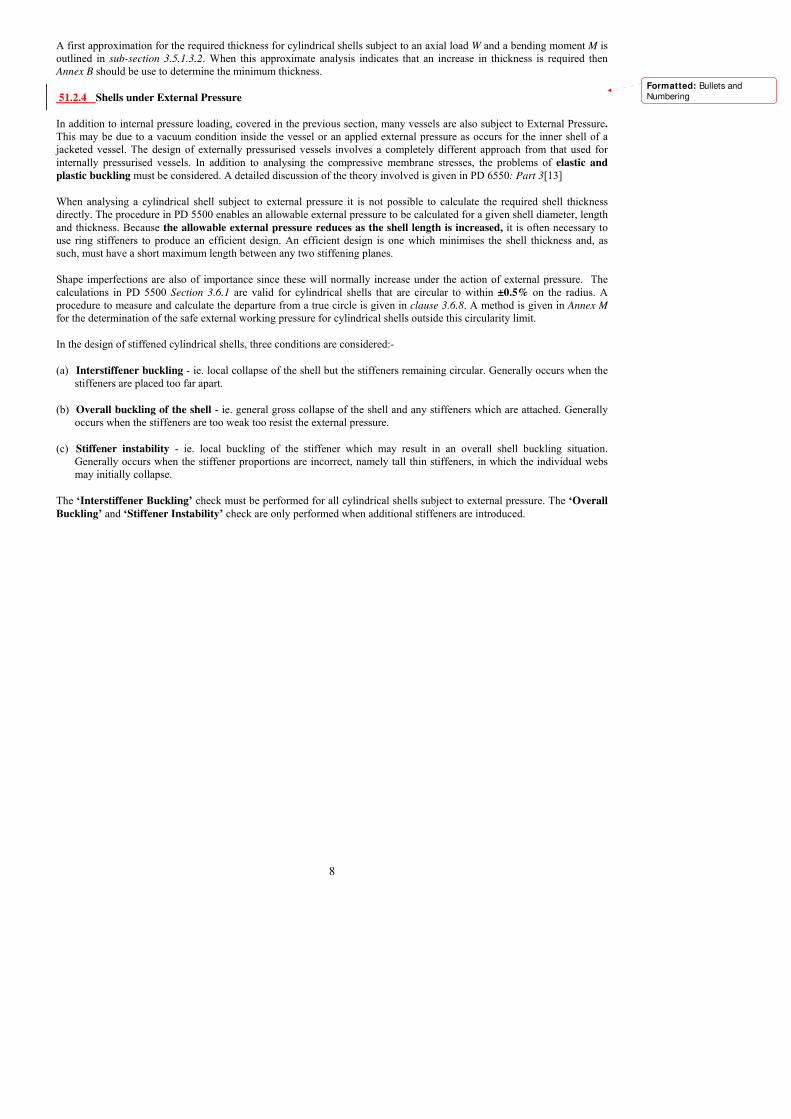
In the design of stiffened cylindrical shells, three conditions are considered:-
(a) Interstiffener buckling - ie. local collapse of the shell but the stiffeners remaining circular. Generally occurs when the
stiffeners are placed too far apart.
(b) Overall buckling of the shell - ie. general gross collapse of the shell and any stiffeners which are attached. Generally
occurs when the stiffeners are too weak too resist the external pressure.
(c) Stiffener instability - ie. local buckling of the stiffener which may result in an overall shell buckling situation.
Generally occurs when the stiffener proportions are incorrect, namely tall thin stiffeners, in which the individual webs
may initially collapse.
The ‘Interstiffener Buckling’ check must be performed for all cylindrical shells subject to external pressure. The ‘Overall
Buckling’ and ‘Stiffener Instability’ check are only performed when additional stiffeners are introduced.
Formatted: Bullets andNumbering
9
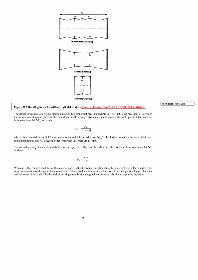
Figure 51.2 Buckling forms for stiffener cylindrical shells (Source: Figure 3.6-2 of PD 5500:2003 edition)
The design procedure allows the determination of two important pressure quantities. The first is the pressure, py, at which
the mean circumferential stress in the cylindrical shell midway between stiffeners reaches the yield point of the material,
from equation (3.6.2-7), as shown:
( )GR
sfep
γ−=
1y
where s is a material factor (1.1 for austenitic steels and 1.4 for carbon steels), f is the design strength, e the vessel thickness,
R the mean radius and γG, a second order term when stiffeners are present.
The second quantity, the elastic instability pressure, pm, for collapse of the cylindrical shell is found from equation (3.6.2-8)
as shown:
R
Eep
ε=m
Where E is the young�s modulus of the material and ε is the theoretical buckling strain for a perfectly circular cylinder. This
strain is a function of the mode shape of collapse of the vessel and it in turn is a function of the unsupported length, diameter
and thickness of the shell. The theoretical bucking strain is given in graphical form and also by a supporting equation.
Formatted: Font: Bold

10
Figure 51.3 Theoretical bucking strain ε as a function of shell length, radius and thickness (SOURCE: Figure 3.6-2 of
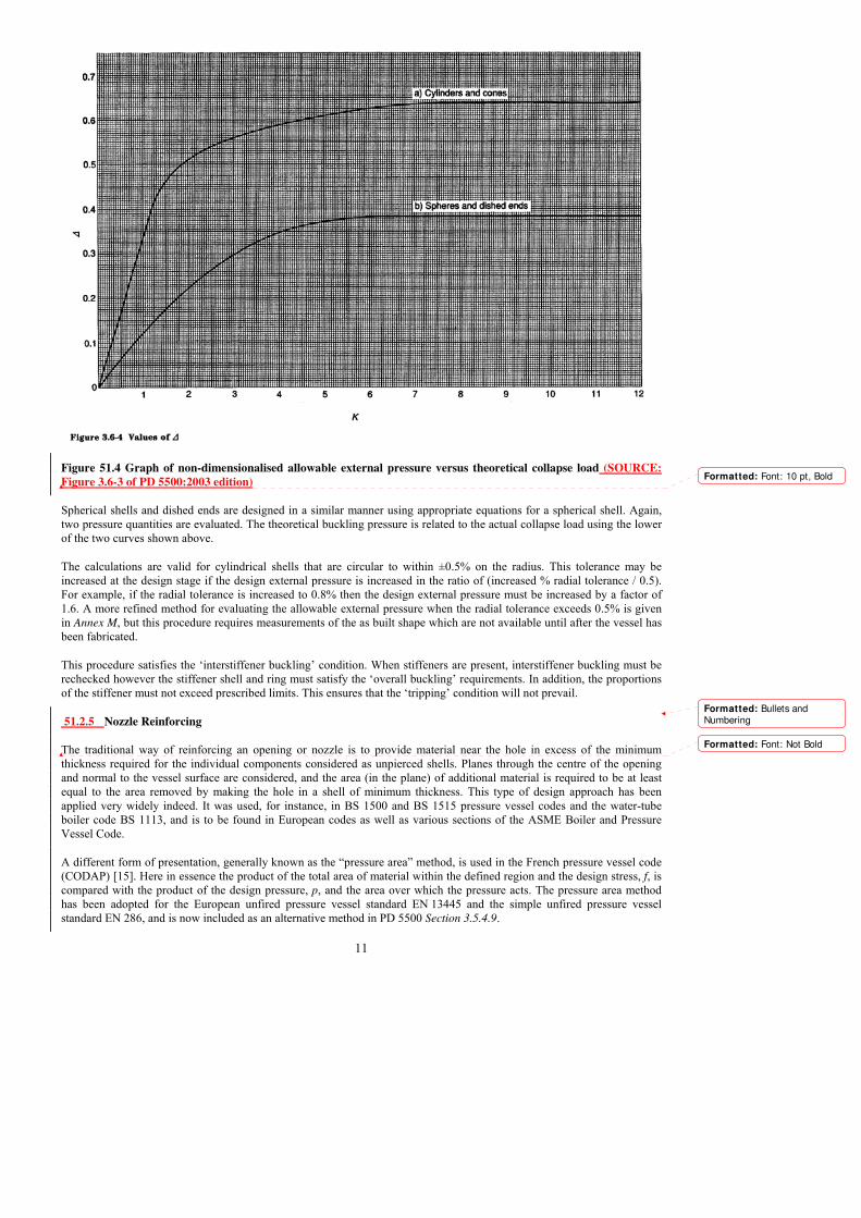
PD 5500:2003 editionIn order to correct for real vessels which may have slight shape imperfections and some residual
compressive stress, a graph was provided by Kendrick [15] which relates the theoretical collapse pressure to the actual
experimental collapse pressure with a 1.5 safety factor. This graph is non-dimensionalised by dividing by the yield pressure
found previously i.e. K=Pm/Py and Δ=Pallow/Py.
Formatted: Font: 10 pt, Bold
Deleted: 
11
Figure 51.4 Graph of non-dimensionalised allowable external pressure versus theoretical collapse load (SOURCE:
Figure 3.6-3 of PD 5500:2003 edition)
Spherical shells and dished ends are designed in a similar manner using appropriate equations for a spherical shell. Again,
two pressure quantities are evaluated. The theoretical buckling pressure is related to the actual collapse load using the lower
of the two curves shown above.
The calculations are valid for cylindrical shells that are circular to within ±0.5% on the radius. This tolerance may be
increased at the design stage if the design external pressure is increased in the ratio of (increased % radial tolerance / 0.5).
For example, if the radial tolerance is increased to 0.8% then the design external pressure must be increased by a factor of
1.6. A more refined method for evaluating the allowable external pressure when the radial tolerance exceeds 0.5% is given
in Annex M, but this procedure requires measurements of the as built shape which are not available until after the vessel has
been fabricated.
This procedure satisfies the �interstiffener buckling� condition. When stiffeners are present, interstiffener buckling must be
rechecked however the stiffener shell and ring must satisfy the �overall buckling� requirements. In addition, the proportions
of the stiffener must not exceed prescribed limits. This ensures that the �tripping� condition will not prevail.
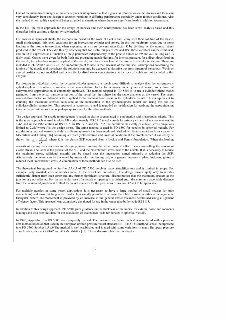
51.2.5 Nozzle Reinforcing
The traditional way of reinforcing an opening or nozzle is to provide material near the hole in excess of the minimum
thickness required for the individual components considered as unpierced shells. Planes through the centre of the opening
and normal to the vessel surface are considered, and the area (in the plane) of additional material is required to be at least
equal to the area removed by making the hole in a shell of minimum thickness. This type of design approach has been
applied very widely indeed. It was used, for instance, in BS 1500 and BS 1515 pressure vessel codes and the water-tube
boiler code BS 1113, and is to be found in European codes as well as various sections of the ASME Boiler and Pressure
Vessel Code.
A different form of presentation, generally known as the �pressure area� method, is used in the French pressure vessel code
(CODAP) [15]. Here in essence the product of the total area of material within the defined region and the design stress, f, is
compared with the product of the design pressure, p, and the area over which the pressure acts. The pressure area method
has been adopted for the European unfired pressure vessel standard EN 13445 and the simple unfired pressure vessel
standard EN 286, and is now included as an alternative method in PD 5500 Section 3.5.4.9.
Formatted: Font: 10 pt, Bold
Formatted: Bullets andNumbering
Formatted: Font: Not Bold
12
One of the main disadvantages of the area replacement approach is that it gives no information on the stresses and these can
vary considerably from one design to another, resulting in differing performance especially under fatigue conditions. Also
the method is not readily capable of being extended to situations where there are significant loads in addition to pressure.
In the UK, the main approach for the design of nozzles and their reinforcement has been stress analysis based and this
thereafter being cast into a design-by-rule method.
For nozzles in spherical shells, the methods are based on the work of Leckie and Penny with their solution of the elastic,
small displacement, thin shell equations for an intersecting cylinder and sphere. In this the maximum stress due to some
loading at the nozzle intersection, when expressed as a stress concentration factor K by dividing by the nominal stress
produced in the vessel. They did this by observing that for useful ranges of r/R and R/T, these variables can be combined,
and the SCF expressed as a function of the ρ parameter independently of the precise values of r/R and R/T so long as ρ is
fairly small. Curves were given for both flush and protruding nozzle designs, for internal pressure, for a direct thrust load on
the nozzle, for a bending moment applied to the nozzle, and for a shear load at the nozzle to vessel intersection. These are
included in PD 5500 Annex G 2.5. An important point to note is that, because of the thin shell assumptions concerning the
joining of the nozzle and the sphere, the solutions can only be expected to describe the gross structural behaviour. Welds or
curved profiles are not modelled and hence the localised stress concentrations at the toes of welds are not included in this
analysis.
For nozzles in cylindrical shells, the cylinder/cylinder geometry is much more difficult to analyse than the axisymmetric
cylinder/sphere. To obtain a suitable stress concentration factor for a nozzle in a cylindrical vessel, some form of
axisymmetric approximation is commonly employed. The method adopted in PD 5500 is to use a cylinder/sphere model
generated from the actual transverse section of the vessel i.e. the sphere has the same diameter as the vessel. The stress
concentration factor so obtained is then applied to the nominal hoop stress in the cylindrical vessel. This is equivalent to
doubling the maximum stresses calculated at the intersection in the cylinder/sphere model and using this for the
cylinder/cylinder connection. This approach is conservative and is regarded as justification for applying the approximation
to rather larger d/D ratios than is perhaps appropriate for the other methods.
The design approach for nozzle reinforcement is based on elastic stresses used in conjunction with shakedown criteria. This
is the same approach as used in older UK codes, namely, BS 3915 (steel vessels for primary circuits of nuclear reactors) in
1965 and in the 1968 edition of BS 1515. In BS 3915 and BS 1515 the permitted elastically calculated stress range was
limited to 2.25f where f is the design stress. The same method is used in PD 5500 for nozzles in spherical vessels. For
nozzles in cylindrical vessels, a slightly different approach has been employed. Shakedown factors are taken from a paper by
Macfarlane and Findlay [16] Assuming a Tresca yield criterion and uniaxial condition at the crotch corner, it can easily be
shown that 12
34s −
−=
K
KK where K is the elastic SCF obtained from a Leckie and Penny formulation. When the loading
consists of cycling between zero and design pressure, limiting the stress range in effect means controlling the maximum
elastic stress. The latter is the product of the SCF and the �membrane� stress near to the nozzle. If it is necessary to reduce
the maximum stress, additional material can be placed near the intersection aimed primarily at reducing the SCF.
Alternatively the vessel can be thickened by means of a reinforcing pad, or a general increase in plate thickness, giving a
reduced local �membrane� stress. A combination of these methods can also be used.
The theoretical background to Section 3.5.4.3 of PD 5500 involves many simplifications and is limited in scope. For
example, only isolated, circular nozzles radial to the vessel are considered. The design curves apply only to nozzles
sufficiently distant from each other and any further significant structural discontinuities that the maximum stresses at the
junction are not affected. For the particular case of a nozzle or opening in a dished end, the minimum acceptable distance
from the vessel/end junction as 1/10 of the vessel diameter for the provisions of Section 3.5.4.3 to be applicable.
For multiple nozzles in some vessel applications it is necessary to have a large number of small nozzles (or tube
connections) and close pitching often results. It is usually possible to arrange the tubes in rows in either a rectangular or
triangular pattern. Reinforcement is provided by an increase in the general vessel thickness determined using a ligament
efficiency factor. This approach was extensively developed for use in the water-tube boiler code BS 1113.
In addition to this design approach, PD 5500 gives guidance on the thickness of the nozzle for external force and moments
loadings and also provides data for the calculation of shakedown loads for nozzles in spherical vessels.
In 1996, Appendix F in BS 5500 was completely revised. The previous calculation method was replaced with a pressure
area method based on that used in the European unfired pressure vessel standard EN 13445 This method is now incorporated
into PD 5500 Section 3.5.4.9.The method is well established and is used with some variations in many European pressure
vessel codes, such as CODAP and AD Merkblatter [17]. This is discussed later in this chapter.

13
51.2.6 Bolted Flanged Joints
Most inspection openings or nozzles on vessels are provided with circular-type standard flanges for quick, easy disassembly
of closing covers or connected piping. Under normal circumstances, when using standard "rated" flanges (such as BS 1560,
BS 4504, BS EN 1092, BS EN 1759 or ASME B16.5), calculations need not be performed since the design of the flange will
have been previously covered and this noted on the supplied test certificate. Only non-standard flanges are designed or
existing flanges checked for maximum working pressures.
There are three main types of circular bolted flange covered in PD 5500 Section 3.8:
(a) Narrow-faced flanges. These are flanges where all the gasket contact area lies inside the circle enclosed by the
bolts and are designed in accordance with sub-section 3.8.3. PD 5500 also covers ungasketed seal welded flanges in
sub-section 3.8.5.
(b) Full-faced flanges. These are flanges where the gasket contact area extends outside the bolt circle. Full-faced
flanges with soft ring-type gaskets are designed in accordance with sub-section 3.8.4. A simple method for full-
faced flanges with metal to metal contact outside the bolt circle is now included in PD 5500, sub-section 3.8.8.
(c) Reverse flanges. Theses are flanges where the shell is attached at the outer edge of the flange. They are used where
there is a requirement to limit the maximum outside diameter of the vessel. Narrow-faced reverse flanges are
designed in accordance with sub-section 3.8.6, and full-faced reverse flanges in accordance with sub-section 3.8.7.
PD 5500 Enquiry Case 5500/133 covers rectangular narrow faced and full-faced flanges.
When standard flanges cannot be used or are not appropriate to the circumstances then it becomes necessary to design the
joint in detail to match specific requirements. PD 5500 provides methods for analysis and design of a range of special
joints, allowing the designer to create a design for the most appropriate joint in a given solution.
Flanged joint behaviour has been the subject of detailed research for many decades. In all this time, probably the most
significant contribution was the paper published in 1937 by Waters, Wesstrom, Rossheim and Williams [18] in which the
authors for the first time, the comprehensive flange design system which became the basis of the well known Taylor Forge
method. The method of analysis used involves modelling the joint elements using simplified plate and shell theory with
known boundary conditions, and then combining the elements to derive stresses in the various parts. This analysis was the
first complete analysis which considered the flange, hub and shell as properly defined entities with minimal approximation.
Wide acceptance and the relative simplicity in its application have made the Taylor Forge method the most widely used
flange design technique in modern use and it forms the basis of the flange design sections of PD 5500, ASME VIII and
many other codes around the world. However, this method involves a number of assumptions which potentially limit its
applicability to certain classes of joints. The technique has suffered from a few problems, most notably the potential for joint
leakage due to the increased flange flexibility of the inherently lighter (and more economic) joints. Although this problem
was later cured by the introduction of an equation limiting flange rotation, the Taylor Forge method remains the prescribed
method in the UK code.
The method requires that the geometry of the joint be specified along with details of the preferred sealing element or gasket.
The gasket requires a certain amount of bolt preload to initialise and provide a seal. This is defined by the parameter �y� and
this factor helps determine the required load for bolt-up. A second parameter, �m�, is related to the ability to seal once
compressed and is used to determine the amount of bolting required to maintain a seal in the operating condition. From these
conditions, the actual bolting requirements can be established and the number and core area of bolts can be fixed. Thereafter,
the various moments are calculated and the stresses in the flange ring and shell hub are evaluated. The stresses are
categorised and limited according to their nature. Membrane stresses are limited to two third of yield and bending stress to
yield. However, the method assumes that the design pressure is used to size the flange ring and if designed to the limit, then
some limited yielding can occur during hydrotest. If leakage does occur during test, then the test should stop, the gasket be
replaced and the test repeated. Some problems have been experienced in certain cases with bolted flanged joints in vessels
with a diameter over 1m. A stress reduction factor, k, has recently been introduced to limit the stress levels in the shell hub
connection. If 1000 < D < 2000 then ⎟⎠⎞
⎜⎝⎛ +=
20001
3
2 Dk , and if D > 2000 then
3
4=k .
Flange calculations are quite complex, and will usually involve several iterations before the design is finalised. Because of
this most flange design is now performed using computer programs.
Formatted: Bullets andNumbering

14
51.2.7 Flat Plates and Covers
Flat ends or domed covers may be used to blank off flanges for pressure tests (blind flange), provide manway closures, or be
used as fixed or removable end closures. This section covers the design rules given in PD 5500 sub-section 3.5.5 for welded
or bolted flat ends, and sub-section 3.5.6 for domed and bolted ends. There are rules governing the design of three groups of
flat ends and plates:
(i) Welded Flat Ends and Covers
(ii) Non-Welded Flat Ends and Covers
(iii) Flat Stayed Plates without openings (not covered in this course)
Any of these ends or covers may be non-circular, and the appropriate factors are included in the design methods. Welded flat
ends are normally used only for small diameter vessels operating at low pressures. This is because of the large bending
stresses induced in a flat plate subject to pressure loading. This results in flat ends being considerably thicker than the
corresponding dished end.
The calculations for the minimum thickness of a circular unstayed flat end are given in sub-section 3.5.5.3.1, and for a non-
circular flat end they are given in Enquiry Case 5500/133.
The basic thickness of a flat end can be evaluated by considering the analysis of a circular plate subject to pressure loading,
see Roark and Young [19],. The most important consideration is the restraint imposed by the connection to the shell. This is
established by the use of a factor, C, which ranges from 0.3 for a clamped edge to 0.41 for a simply supported edge.
f
pCDe =
In addition, the stresses in the shell at the edge of the plate can be evaluated and these are limited to 2.7f. This should be
compared with 3f allowed in PD 5500 Annex A, clause A.3.4.2.4. The lower value provides some ability to accept additional
loads.
For flat bolted covers, the methods are similar to those for flat plates with the addition of a term to account for the stresses
induced by the bolting.
The method in Section 3.5.6 of PD 5500 allows the design of a dished closure or head connected to a flanged ring with a
suitable narrow faced gasket to be evaluated. The procedure is similar to the ASME method and to other international
codes. The analysis is somewhat simplified and empirical factors are introduced to take account of the discontinuity forces
which interact between the two components.
5.1.2.8 Jacketed Vessels
The rules for the design of jacketed vessels are given in Section 3.11 of PD 5500 as part of the main design section. The
reason for the adoption of a jacket is to provide either ‘heating or cooling’ to the main vessel contents. In addition, the
jacket may provide a sealed insulation chamber for the vessel. The use of such jacketed vessels is primarily found in the
process industry and these types of vessels are usually cylindrical in construction. Jackets are traditionally fabricated in the
form of an additional shell belt, this encompassing part or all of the main vessel shell. In addition to this type, jackets can
often encompass the lower dished head.
Formatted: Bullets andNumbering
Formatted: Bullets and
Numbering
15
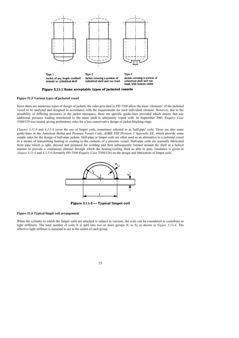
Figure 51.5 Various types of jacketed vessel
Since there are numerous types of design of jackets, the rules provided in PD 5500 allow the main �elements� of the jacketed
vessel to be analysed and designed in accordance with the requirements for each individual element. However, due to the
possibility of differing pressures in the jacket interspace, there are specific guide-lines provided which ensure that any
additional pressure loading transferred to the main shell is adequately coped with. In September 2001 Enquiry Case
5500/128 was issued, giving preliminary rules for a less conservative design of jacket blocking rings.
Clauses 3.11.4 and 4.3.5.4 cover the use of limpet coils, sometimes referred to as 'half-pipe' coils. There are also some
guide-lines in the American Boiler and Pressure Vessel Code, ASME VIII Division 1 Appendix EE, which provide some
simple rules for the design of half-pipe jackets. Half-pipe or limpet coils are often used as an alternative to a jacketed vessel
as a means of transmitting heating or cooling to the contents of a pressure vessel. Half-pipe coils are normally fabricated
from pipe which is split, dressed and prepared for welding and then subsequently formed around the shell in a helical
manner to provide a continuous channel through which the heating/cooling fluid as able to pass. Guidance is given in
clauses 3.11.4 and 4.3.5.4 (formerly PD 5500 Enquiry Case 5500/126) on the design and fabrication of limpet coils.
Figure 51.6 Typical limpit coil arrangement
When the cylinder to which the limpet coils are attached is subject to vacuum, the coils can be considered to contribute as
light stiffeners. The total number of coils N is split into two or more groups N1 to Nn as shown in Figure 3.11-4. The
effective light stiffener is assumed to act at the centre of each group.

16
Figure 51.7 Limpit coil arrangement for use in stiffening for external pressure loading
This approach allows the use of the limpit coil as an effective stiffener against shell buckling.
51.2. 9 Welded joints and Manufacture and Workmanship
PD 5500 has sections on both welded joint shape and form but little on the structural design for strength. There are some
helpful comments on manufacture and workmanship including useful information on pre-heating for welding, stress
relieving and shape measurements. This is not discussed in detail here.
51.2.10 Inspection and Testing
The standard test pressure for a vessel section to PD 5500 shall be not less that pt, where: ⎥⎦
⎤⎢⎣
⎡−
×=ct
t
f
fpp
t
a
t 25.1 where
fa and ft are the design strengths at ambient and temperature respectively, t is the shell thickness and c is the corrosion
allowance. This allows the vessel to be tested at room temperature but factor in the changes in stress at high temperature and
also when the vessel is corroded.
This equation applies to all levels of construction. Where the vessel to be tested comprises a number of non-connected parts
(as in a heat exchanger) then each part is tested independently with the appropriate 'standard' test pressure. There are
particular cases which require special consideration. These include glass lined vessels or those where coating could be
damaged, vessels under external pressure and jacketed vessels. A full description of the limits of the �standard� test pressure
and the applicable test pressures for all other cases are given in section 5.8.5.
Where a component is subjected to an internal test pressure that is greater than 1.08 times the 'standard' test pressure then a
design check must be carried out to ensure that the general membrane stress in that component during the test does not
exceed 90% of the minimum specified yield or proof stress of the material.
For vertical vessels the effect of the pressure due to the static head of the test liquid must be considered. Tall vessels are
normally tested horizontally in the shop, but may be required to be tested vertically at site. For large vessels the weight of
the test liquid will be considerable (a cubic metre of water weighs 1 tonne), and may control the design of the supports.
51.2.11 Supports
PD 5500 Section 3.7 and Annex G, Section G.3 are concerned with the supports for pressure vessels (and other fittings)
which are carried by the shell or ends of a pressure vessel. The main design consideration is to understand the effect of these
supports on the shell. No account is made of the support design. These can normally be designed by the usual structural
methods. PD 5500 gives some general information about supports and attachments, but does not contain any calculation
procedures. Supports produce local moments and membrane forces in the vessel wall and these are treated by applying the
rules for Local Loads on Pressure Vessel Shells in PD 5500 Annex G, Section G.2, with the exception of saddle supports
which will be dealt with in detail here. The assessment of stresses in saddle mounted vessels is covered by Annex G, sub-
section G.3.3. A derivation of the equations and constants used in sub-section G.3.3 is given in PD 6497 [20].
When vessels are supported in the horizontal plane, they are subject to longitudinal bending moments and local shear forces
due to the weight of the vessel and its contents. In addition to these, local stresses arise at the support or fitting. A vessel
Formatted: Bullets andNumbering
Formatted: Bullets and
Numbering
Formatted: Bullets andNumbering
17
may be designed to be located in the vertical position in service, but most vessels, both horizontal and vertical, are
constructed and transported in the horizontal position. Some vertical vessels may also have their hydraulic pressure test in
the horizontal position.
In all cases, it is preferable to support the vessel at two profiles, equidistant from each end. If the vessel is very flexible, or is
subject to external pressure, then ring supports may be required. However, under normal circumstances, saddle supports are
the most commonly used method of supporting such vessels during fabrication, transportation and in service. It is noted that
leg supports are used for small L/r ratios where the longitudinal stresses are small in comparison to the axial stresses in the
shell due to pressure.
This arrangement means that the vessel acts like a beam in bending and this area requires to be considered at the design
stage. Unlike the ring support, the shell is only supported over part of its circumference, typically 120° wraparound, and
high stresses can occur at several areas in the plane of the saddle. Therefore, the twin saddle support problem is one of the
more complex problems covered in PD 5500 and is not discussed in detail herein.
The procedure, based on the work of Zick [21] and implemented into PD5500 by Tooth [22] can be broken down into four
main design elements. When the vessel is situated on twin saddles, the following high stress (f) areas must be investigated:
(i) longitudinal bending stresses at the vessel mid-span ie. f1 at the highest and f2 at the lowest sections
(ii) longitudinal stresses at the saddles i.e. f3 at the highest or equator and f4 at the lowest sections
(iii) tangential shearing stresses at the saddles i.e. q (and qe when saddle is near the end)
(iv) circumferential stresses at the saddles i.e. f5 at the lowest and f6 at the horn sections.
Each of these stresses must be assessed against specific criteria depending on the influence of other loads and the possible
failure mode (e.g. plastic deformation or buckling collapse).
Consideration must be given to establishing the bending moments at the mid-span and at the plane of the support. Thereafter
a series of factors are derived which relate the location of the support with respect to the end. If the support is near the vessel
end, then the shell remains circular and the full section is available to resist bending. If not, then only a partial section is
available. The highest stress is often at the saddle horn, where the shell �bends� over the support and has little or no
resistance to radial deformation. Again, various factors are evaluated and the stress, f6 determined. However the absolute
value of f6 should not exceed 1.25f. This is significantly different from the 3f secondary stress limit which should be used.
This reduction is present due to the assumptions in the method and also that work by Tooth has shown the method to under
predict stress levels when the support is �rigid� i.e. like a concrete or very substantial support. For flexible saddles, the
method provides reasonable agreement with experiments.
If the value of the stress f6 calculated using the above method is less than 1.25f then this will provide adequate safety margin
for static loading conditions, however this value of f6 is not appropriate for use in a fatigue assessment [23]. A procedure is
given in sub-section G.3.3.2.8 for the determination of a maximum stress, that when added to the stress due to pressure, can
be used in a fatigue analysis to Annex C.
51.2.12 Local Loads
Nozzles and attachments such as legs, brackets and trunnions are often subjected to applied forces and moments. These
loads produce local stresses in the vessel at the edge of the nozzle or attachment. Annex G.2 contains methods for calculating
these stresses for local loads on either cylindrical or spherical shells. Stresses due to pressure must also be considered. The
calculated stresses due to the various loadings are combined and assessed in accordance with the requirements of Annex A.
The calculation methods presented in PD 5500 Annex G.2 for the analysis of cylindrical and spherical shells subject to local
loads have different approaches. Whilst they are both design-by-analysis methods, i.e. choose geometry and loading and
solve a stress problem, they are inherently different in their approaches. A detailed discussion of the theory and development
of the calculation methods in Annex G.2 is contained in the text, 'Pressure Vessel Design - Concepts and principles� by
Spence and Tooth [24].
New alternative methods are also given in sub-section G.2.7. These are based on the methods used in the new European
standard for unfired pressure vessels EN 13445, and allow the maximum permissible loads and moments on nozzles in
cylindrical and spherical shells to be calculated.
Local Loads on Cylindrical Shells
Formatted: Bullets andNumbering

18
The method for local loading on cylindrical shells is based on the solution for a uniform radial line load represented as a
Fourier series acting on a thin cylindrical shell. In order to obtain the solution for a rectangular radially loaded area, such as
a support bracket, stress and deflection results for the line load were integrated around the circumference of the shell and
plotted as Figures G.2.2-6 to G.2.2-9. Plotting in this manner minimised the number of charts required for the stress
analysis.
Externally applied moment loading is represented by two equal and opposite rectangular radially loaded areas. This
representation allows the original integrated line load data to be used to evaluate stresses for moment loading. Since the
moment load is represented by two rectangular areas which, depending on the actual patch size, may be quite close to one
another. If the two patches interact, the stresses resulting at the outer edge of one patch may be affected by the die-out length
on the second loaded area. Additional data is provided in Annex G to allow this interaction and overall die-out to be
assessed.
Once the stresses from each load component are evaluated, they must be combined and added to the stresses caused by
pressure loading. Annex G provides the appropriate equations to evaluate the stresses in a cylindrical shell due to pressure
loading only. Stresses are combined in accordance with the Quadrant Method and assessed according to the limitations of
Annex A.
Other shapes of loaded area, such as circular or elliptical, are represented by evaluating the equivalent loaded rectangular or
square area. Limitations on the vessel/attachment geometry are also given since the method may be unreliable outside these
limits.
The method is slightly different from that contained in WRC Bulletin 107 [25] where the loading is represented explicitly by
a double Fourier series. The representation of a moment loading is by a triangular distribution rather than the two equal and
opposite radial loads in PD 5500. However, the results obtained by each method have been shown to be very similar [26].
Local Loads on Spherical Shells
Methods are provided for calculating stresses and deflections due to externally applied radial loads and moments applied to
spherical shells.
If the attachment is rigid, stresses and deflections are evaluated using equations and graphs as detailed in sub-section G.2.4.
Each stress resultant is evaluated in turn and the resulting stresses are then combined with pressure stresses.
Sub-section G.2.5 is based on the work of Leckie and Penny [27] and deals with the evaluation of the maximum principal
stress which can occur at a nozzle/sphere attachment due to the application of internal pressure, thrust, external moment and
shear force. The method covers both flush and protruding nozzles, however, although the original theory assumes semi-
infinite nozzle lengths a minimum length of protrusion equal to rt2 is required if the attachment is to be regarded as
protruding. Otherwise, the attachment must be considered flush. If the vessel is subjected to cyclic loading through the
attachment, then the shakedown load may be of interest. By keeping the cyclic loadings within the shakedown limit the
method ensures that, after initial plastic deformation, further deformation will be in the elastic region, i.e. the vessel has
�shaken down� to purely elastic behaviour. Sub-section G.2.6 provides the shakedown factors for various loads and the
interaction of these under combined load conditions. This method is based on the �maximum shear stress� theory.
51.2.13 Design for Fatigue
Fatigue assessment of pressure vessels is normally applied as a checking procedure � after the vessel has been fully designed
in terms of dimensions and details. The objective normally is to estimate the fatigue service life for comparison with the
notional or explicitly desired fatigue life. Consideration needs to be given in fatigue checking to three main topic areas,
namely, the load variation, the stress concentration, and the fatigue properties of the material. All fatigue checking
procedures direct attention to these three areas, although they may deal with the problem in different ways. Fatigue
properties are generally quoted in terms of constant amplitude stress or strain cycling, whereas real structures are normally
subject to variable amplitude patterns � e.g. start-up to full pressure, followed by thermal loading, with superimposed
mechanical vibrations, etc. The effect of various numbers of cycles at different amplitudes in succession is normally
assessed using a cumulative damage law, the most common being Miner�s Rule. In this method the �damage� caused by ni
cycles of a particular amplitude Sai is accounted for by the term ni/Ni, where Ni is the number of cycles of constant amplitude
at Sai which will produce failure. The damage therefore sums up as;
∑ ++= etcN
n
N
n
N
n...
2
2
1
1
i
i
Formatted: Bullets andNumbering

19
and failure occurs when the sum reaches unity. Use of this law implies that the order of application of the loads does not
affect the result and that there are no time-dependent effects. Some codes have also introduced a safety factor by limiting
damage summation to 0.6 or some other fraction.
Annex C describes the current mandatory approach to fatigue checking in PD 5500.
The main reason for developing the approach in the revised Annex C was that the philosophy on which the previous method,
developed from the ASME method, was based was inappropriate for weld areas in vessels where fatigue failures are mostly
likely. The assessment of load variation is virtually the same in both approaches, the main differences being in the
philosophies used to assess and link the stress concentration effects and the fatigue strength/life property curves
(hereinafter called �S/N curves�).
In the ASME approach only one S/N curve was given to cover all metallic materials used in the vessel, aside from bolts.
This curve was based on data obtained by testing flush-ground welds under strain control (hence without significant stress
concentration effect) and the design curve was set four standard deviations below the mean of the test results to give a safety
margin (equivalent to a factor of 2.2 on stress and 15 on life). The curve was expressed in terms of stress amplitude Sa
(being half the stress range) and in the units used in the Standard, the linear part can be represented by the equation:
125.3
a 101.1 ×=NS
which is typical of the log-log form for fatigue curves.
Figure 51.8 ASME based/old BS 5500 fatigue design curve (SOURCE: Figure C.2.1 of BS 5500:1994 edition)
The peak stress amplitude in the region of the vessel to be assessed was then calculated in terms of the nominal stress
amplitude times a universal stress concentration factor of 2.5 for any detail other than a smoothly dressed weld or a threaded
member.
The following table illustrates the different bases of the ASME and the current Annex C.
Formatted: Font: 10 pt, Bold
20
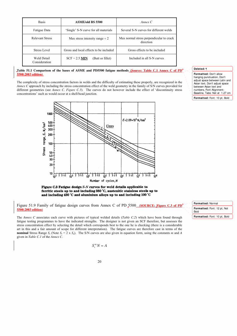
Basis ASME/old BS 5500 Annex C
Fatigue Data �Single� S-N curve for all materials Several S-N curves for different welds
Relevant Stress Max stress intensity range ÷ 2 Max normal stress perpendicular to crack
direction
Stress Level Gross and local effects to be included Gross effects to be included
Weld Detail
Consideration
SCF = 2.5 MIN (Butt or fillet) Included in all S-N curves
Table 51.1 Comparison of the bases of ASME and PD5500 fatigue methods (Source: Table C.1 Annex C of PD
5500:2003 edition)
The complexity of stress concentration factors in welds and the difficulty of estimating these properly, are recognized in the
Annex C approach by including the stress concentration effect of the weld geometry in the family of S/N curves provided for
different geometries (see Annex C, Figure C.3). The curves do not however include the effect of �discontinuity stress
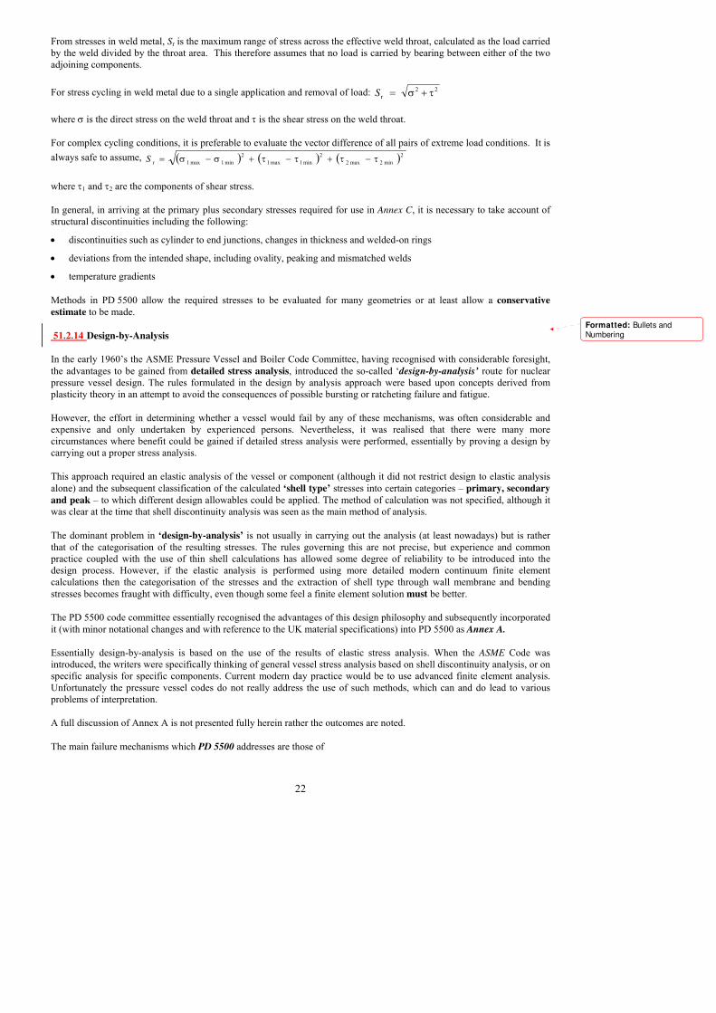
concentrations� such as would occur at a shell/head junction.
Figure 51.9 Family of fatigue design curves from Annex C of PD 5500 (SOURCE: Figure C.3 of PD
5500:2003 edition)
The Annex C associates each curve with pictures of typical welded details (Table C.2) which have been found through
fatigue testing programmes to have the indicated strengths. The designer is not given an SCF therefore, but assesses the
stress concentration effect by selecting the detail which corresponds best to the one he is checking (there is a considerable
art in this and a fair amount of scope for different interpretation). The fatigue curves are therefore cast in terms of the
nominal Stress Range Sr (Note Sr = 2 x Sa). The S/N curves are also given in equation form, using the constants m and A
given in Table C.1 of the Annex C.
ANS =m
r
Formatted: Don't allowhanging punctuation, Don't
adjust space between Latin andAsian text, Don't adjust spacebetween Asian text andnumbers, Font Alignment:
Baseline, Tabs: Not at 1.27 cm
Formatted: Font: 10 pt, Bold
Formatted: Normal
Formatted: Font: 12 pt, Not
Bold
Formatted: Font: 10 pt, Bold
Deleted: 

21
ASME stresses and Stress Concentration factors
The ASME is based on a single S-N curve originating from uni-axial tests on flush-ground butt weld specimens. The
relevant stress in this procedure was the ‘Alternating Stress Intensity’ denoted as Salt, and defined as: ralt 5.0 SS = where Sr
is the absolute magnitude of the stress intensity. It is noted that the stress intensity is the maximum absolute value of the
stress differences of the three principal stresses. It is worth noting that the values of the principal stresses may change
throughout a load cycle and therefore, the designer should ensure that the maximum stress differences are considered with
respect to time over the whole cycle. The above procedure relates primarily to the case where the principal stress direction
remains constant over the load cycle. In those cases where the principal stress directions change, the range of fluctuation
should be determined from the stress differences in order to find the full algebraic range. It may be necessary to try various
points in time to find the one which results in the largest value of the alternating stress intensity.
There are various features of a vessel and the weld which will reduce the fatigue life of the component. These are dealt with
by multiplying the nominal stress by an appropriate �stress concentration factor� (SCF) or �fatigue reduction factor� in
calculating the peak stress. Stress concentration factors are not given explicitly but made reference to various well known
publications in its bibliography.
An SCF of one was assumed for a dressed smooth butt weld. A stress concentration factor of �at least 2.5� was used for the
toe of an as-welded butt or fillet weld. For a contour dressed fillet weld, the stress concentration would be dependent on the
local geometry and suitable SCF values had to be obtained from technical literature [28].
PD 5500 stresses
In Annex C, the fatigue assessment is based on the �primary plus secondary stress� category. �Direct stress� is used rather
than the stress intensity which is used elsewhere in PD 5500. The full stress range is used, regardless of applied or mean
stress since the design S-N curves provided, take into account the effects of peak and residual stresses.
However, the fatigue curves for bolting do not take account of stress concentrations in the bolt and the stress range should
include a suitable concentration factor � see Annex C, clause C.3.3.4.
When the directions of the principal stresses remain fixed, then Sr is the maximum range through which any of the principal
stresses changes:
min3max3
min2max2
min1max1
ff
ff
ff
−−−
where f1, f2 and f3 are the three principal stresses. Usually f3 is rarely relevant and can often be ignored.
If the principal stress directions change, then the three direct and three shear components must be determined and thereafter,
for each stress component, the algebraic difference between the stresses must be found. From this, the principal stresses can
be found and Sr is the greatest of these principal stresses.
22
From stresses in weld metal, Sr is the maximum range of stress across the effective weld throat, calculated as the load carried
by the weld divided by the throat area. This therefore assumes that no load is carried by bearing between either of the two
adjoining components.
For stress cycling in weld metal due to a single application and removal of load: 22
r τ+σ=S
where σ is the direct stress on the weld throat and τ is the shear stress on the weld throat.
For complex cycling conditions, it is preferable to evaluate the vector difference of all pairs of extreme load conditions. It is
always safe to assume, ( ) ( ) ( )2
min2max2
2
min1max1
2
min1max1r τ−τ+τ−τ+σ−σ=S
where τ1 and τ2 are the components of shear stress.
In general, in arriving at the primary plus secondary stresses required for use in Annex C, it is necessary to take account of
structural discontinuities including the following:
• discontinuities such as cylinder to end junctions, changes in thickness and welded-on rings
• deviations from the intended shape, including ovality, peaking and mismatched welds
• temperature gradients
Methods in PD 5500 allow the required stresses to be evaluated for many geometries or at least allow a conservative
estimate to be made.
51.2.14 Design-by-Analysis
In the early 1960�s the ASME Pressure Vessel and Boiler Code Committee, having recognised with considerable foresight,
the advantages to be gained from detailed stress analysis, introduced the so-called �design-by-analysis’ route for nuclear
pressure vessel design. The rules formulated in the design by analysis approach were based upon concepts derived from
plasticity theory in an attempt to avoid the consequences of possible bursting or ratcheting failure and fatigue.
However, the effort in determining whether a vessel would fail by any of these mechanisms, was often considerable and
expensive and only undertaken by experienced persons. Nevertheless, it was realised that there were many more
circumstances where benefit could be gained if detailed stress analysis were performed, essentially by proving a design by
carrying out a proper stress analysis.
This approach required an elastic analysis of the vessel or component (although it did not restrict design to elastic analysis
alone) and the subsequent classification of the calculated ‘shell type’ stresses into certain categories � primary, secondary
and peak � to which different design allowables could be applied. The method of calculation was not specified, although it
was clear at the time that shell discontinuity analysis was seen as the main method of analysis.
The dominant problem in ‘design-by-analysis’ is not usually in carrying out the analysis (at least nowadays) but is rather
that of the categorisation of the resulting stresses. The rules governing this are not precise, but experience and common
practice coupled with the use of thin shell calculations has allowed some degree of reliability to be introduced into the
design process. However, if the elastic analysis is performed using more detailed modern continuum finite element
calculations then the categorisation of the stresses and the extraction of shell type through wall membrane and bending
stresses becomes fraught with difficulty, even though some feel a finite element solution must be better.
The PD 5500 code committee essentially recognised the advantages of this design philosophy and subsequently incorporated
it (with minor notational changes and with reference to the UK material specifications) into PD 5500 as Annex A.
Essentially design-by-analysis is based on the use of the results of elastic stress analysis. When the ASME Code was
introduced, the writers were specifically thinking of general vessel stress analysis based on shell discontinuity analysis, or on
specific analysis for specific components. Current modern day practice would be to use advanced finite element analysis.
Unfortunately the pressure vessel codes do not really address the use of such methods, which can and do lead to various
problems of interpretation.
A full discussion of Annex A is not presented fully herein rather the outcomes are noted.
The main failure mechanisms which PD 5500 addresses are those of
Formatted: Bullets andNumbering

23
• Gross plasticity: - large, obvious bulges in the shell
• Incremental Collapse (or ratcheting): - collapse by repeated load cycling which increments the amount of plasticity
through the thickness
• Buckling: - general collapse of the shell into a number of modes, normally attributed to compressive loads and applied
external pressure
• Fatigue: - repeated load cycling, either mechanical or thermal which continually impairs the material and induces a
material breakdown.
Once an analysis has been carried out, there follows the process of assigning the resulting stresses into specific categories
depending on the nature and source of the stress and its location and influence on adjacent components.
Different limits are applied to stress categories, as shown in Figure A.1 of Annex A. Primary stresses are limited for gross
deformation. Primary plus secondary stresses are limited by the shakedown limit. Summarising the rules and their
limitations gives
• Primary membrane stresses are limited by f
• Local primary membrane by 1.5f
• Primary membrane plus bending by 1.5f
• Primary membrane plus bending plus secondary stress by 3f
Typical cases of stress classification are given in Table A.1 of Annex A. A hopper diagram is also provided which acts as an
aid to the combination of the stress components and shows the allowable limits of stress intensity for these groups.
The peak component of stress only needs to be included if a fatigue assessment other than Annex C is used, in which case it
is added to primary membrane and bending and secondary stresses. It is the component of stress left over from the averaging
and linearisation process. The peak stress category, as defined in A.3.4.2.5 includes the contribution of all primary,
secondary and peak stresses.

24
Figure 51.10 Annex A Stress categories and limits of stress intensity - Hopper diagram (SOURCE: Figure A.1 of
PD 5500:2003 edition)Specific Criteria for Limited Application
The criteria of PD 5500 A.3.3.1 through A.3.3.3 provide stress intensity limits for elastically calculated stresses adjacent to
attachments, supports, nozzles and openings. These components are normally subjected to combined effects from pressure
and from externally applied loads.
These apply to attachments and supports, under certain load restrictions, i.e. the load being distributed over and area with
less that 120° circumferential encompassment. Assuming this restriction is satisfied, the concentrating effects can be ignored
and conventional shell pressure stresses can be used as the basis for the design.
For this case, the membrane stress intensity is limited to 1.2f, and the membrane plus bending stress intensity is limited to 2f.
Reference needs to be made to Sec. A.3.4.1 for terminology. For nozzles and openings the maximum stress intensity can be
found from Annex G, in a certain geometry range (G.2.3.5.2 (a) for cylindrical shells or G.2.5.2 for spherical shells). This is
limited, for membrane and bending stress only, to 2.25f. Additional stress limits are also provided for localised buckling (but
the reasoning for this is not entirely clear!)Where shear stress is present alone, it shall not exceed 0.5f. The maximum
permissible bearing stress shall not exceed 1.5f.
51.2.15 Tubesheets
Section 3.9 of PD 5500 provides a comprehensive treatment of the design of the tubesheets for a range of styles of heat
exchanger. This is a somewhat complex subject and is not treated fully herein. Further guidance on the topic can be found in
PD6550 Part 4 [30].
51.3 EN 13445
EN 13445 was developed as a harmonised standard for use with the Pressure Equipment Directive and is intended to cover
the Essential Safety Requirements of the PED. Use of the CEN standard is not mandatory in the PED, but vessels designed,
manufactured and tested in accordance with the CEN standard will have an automatic presumption of conformity with the
essential safety requirements of the Directive.
Formatted: Font: 11 pt, NotBold
Formatted
Formatted: Font: 10 pt, Bold
Formatted
Formatted: Font: 10 pt, Bold
Formatted: Bullets and
Numbering
Deleted: 

25
The major difference from other pressure vessel standards and codes is that there is (or should be) no reference in the
standard to the responsibilities of the parties - the Purchaser, Manufacturer and Independent Inspection Authority. This
aspect is covered by the Directive.
There are some safety matters that the Directive says must be considered (e.g. venting and draining, external fire, etc.), not
all of which are mentioned in the standard.
The general layout of the standard and the philosophy behind it are similar to the UK approach in PD 5500:2000. There is
naturally some common material since BS 5500 was always a well regarded and well maintained standard, but there are
beneficial new methods for dished ends, flanges, tubesheets, expansion bellows and vessels of rectangular section. In recent
years there has been a tendency for EN 13445 and PD 5500 to converge as new methods or improvements to existing
methods in the standard have been incorporated into PD 5500.
Various safety factors are provided by the Directive and are copied over verbatim. Actually they were firstly agreed by the
code writers at an early stage and then transferred into the Directive. Now they are in the PED they can only be modified
with great difficulty.
The standard comprises the following parts:
Part 1: General
Part 2: Materials
Part 3: Design
Part 4: Manufacture
Part 5: Inspection and testing
Part 6: Additional requirements for design and fabrication of pressure vessels and vessel parts constructed of spheroidal
graphite cast iron.
Each part contains various annexes, including an Annex Z which lists the clauses of the standard addressing the essential
safety requirements and other provisions of the PED. (There is a similar Annex Z in PD 5500). It is noted in common with
other CEN standards, EN 13445 uses a comma for the decimal point.
51.3.1 Part 1: General
This part gives the scope of the standard and contains some general definitions, responsibilities of the manufacturer, and
requirements for symbols and units.
51.3.2 Part 2: Materials
This part gives general requirements for materials and lists the various CEN standards for materials. It has several annexes
containing specific requirements, including those for prevention of brittle fracture (similar to Annex D in PD 5500).
There are no tables of design stresses. The evaluation of design stresses from the properties of the material is covered in Part
3.
Carbon steels, low alloy steels and austenitic stainless steels are included, but non-ferrous materials are not yet covered.
Creep is also not covered in the standard, but work is in hand.
51.3.3 Part 3: Design
The first six sections of Part 3 deal with general matters, such as definitions, symbols and abbreviations, basic design criteria
and design stresses.
Section 3: Definitions provides clarity in some areas that is an improvement over PD 5500. Distinctions are made between
design pressure and calculation pressure, and between design temperature and calculation temperature. These are
particularly relevant for heat exchangers. A distinction is also made between required thickness, analysis thickness and
nominal thickness (now adopted by PD 5500).
Formatted: Bullets andNumbering
Formatted: Bullets and
Numbering
Formatted: Bullets andNumbering

26
Section 5: Basic Design Criteria includes information on corrosion, loadings, design methods, thickness, weld joint
coefficients and design of welded joints.
General. The requirements are applicable when:
a) The materials and welds are not subject to localised corrosion in the presence of products which the vessel is to contain,
and
b) The design is outside the creep range.
Note: This will be changed when the section on creep design is prepared.
Corrosion. There is some clear guidance given for cases where reduction of wall thickness is possible as a result of surface
corrosion. Note: The minimum corrosion allowance of 1 mm in the 1999 draft has been removed.
Load cases. A familiar looking list of loadings is provided, which must be taken into account in the design of a vessel. In
EN 13445 these are defined as actions.
a) internal and/or external pressure;
b) maximum static head of contained fluid under operating conditions;
c) weight of the vessel;
d) maximum weight of contents under operating conditions;
e) weight of water under hydraulic pressure test conditions;
f) wind, snow and ice loading;
g) earthquake loading;
h) other loads supported by or reacting on the vessel, including loads during transport and installation.
When necessary, consideration shall be given to the effect of the following loads in cases where it is not possible to
demonstrate the adequacy of the proposed design e.g. by comparison with the behaviour of other vessels:
i) stresses caused by supporting lugs, ring, girders, saddles, internal structures or connecting piping or
intentional offsets of median lines on adjacent components;
j) shock loads caused by water hammer or surging of the vessel contents;
k) bending moments caused by eccentricity of the centre of the working pressure relative to the neutral axis
of the vessel;
l) stresses caused by temperature differences including transient conditions and by differences in coefficients
of thermal expansion;
m) stresses caused by fluctuations of pressure and temperature and external loads applied to the vessel;
n) stresses caused by decomposition of unstable fluids.
Classification of load cases identifies three classes:
a) normal operating load case
b) exceptional load cases (e.g. internal explosion)
c) testing load cases.
Note: Higher nominal design stresses may be used for exceptional load cases.
Failure modes considered in this Part (i.e. Part 3 Design) specifies five failure modes considered:
a) gross plastic deformation (GPD);
b) plastic instability (burst);
c) elastic or plastic instability (buckling);
d) progressive deformation (PD);
e) fatigue.

27
Design Methods provides the all important design philosophy. In addition to the design by rule methods given in section 5,
two alternative methods can be used � design by analysis (DBA) which is covered in Annexes B and C, and experimental
techniques. Very little guidance is currently given on the experimental techniques approach.
The rules in Part 3 provide satisfactory designs for vessels where the number of full pressure cycles does not exceed 500.
Weld Joint Coefficient. A major difference between EN 13445 and PD 5500 is the use of weld joint coefficients which
depend on the extent of NDE applied to the governing welded joints. The level of NDE is determined by the testing group
(similar to construction category in PD 5500) � see Table 6.6.1-1 in Part 5 of EN 13445.
Table 51.3 Nominal design stresses: (Source: Table 6 -1 of EN13445:2002 edition. Formatted: Font: 10 pt, Bold

28
Although weld joint coefficients are not used in PD 5500, for construction category 3 lower design stresses are used to
compensate for the lack of NDT, which is a similar concept to a joint coefficient.
The weld joint coefficients are similar to those in ASME VIII Div. 1.
• For testing group 1 (100% NDE) weld joint coefficient z = 1.
• For testing group 2 (10% to 100% NDE) weld joint coefficient z = 1.
Initially the UK were concerned that it would not be possible to use a joint factor of 1 with partial NDE (category 2 in
PD 5500). However testing group 2 allows just that for well established automatic welding.
• For testing group 3 (10% or 25% NDE depending on material) weld joint coefficient z = 0.85.
• For testing group 4 (0% NDE) weld joint coefficient z = 0.7. However, for testing group 4 the nominal design stress is
also multiplied by 0.9 for normal design conditions.
A single testing group shall normally be applied to an entire vessel, but combinations of testing groups 1, 2 and 3 are
permitted, subject to certain limitations.
Joggle joints, permanent backing strips and lap joints are dealt with in 5.7.4.
Section 6. Nominal Design Stresses contains rules for evaluating allowable stresses for design (similar to section 2.3.3 in
PD 5500). These are summarised in Table 51.3 Nominal design stresses for pressure parts other than bolts.
Table 51.2 Testing groups for steel pressure vessels (Source: Table 6.6.1-1 of EN13445:2002 edition)
Normal operating load cases a) b) Testing and exceptional load cases b)
Steels other
than
austenitic ⎟⎟⎠
⎞⎜⎜⎝
⎛=
4.2;
5.1min 20//2.0 mtp RR
f ⎟⎟⎠
⎞⎜⎜⎝
⎛=
05.1min
/2.0 testtp
test
Rf
Austenitic
steels A ≥ 30
% ⎟⎟⎠
⎞⎜⎜⎝
⎛=
5.1
/0.1 tpRf ⎟⎟
⎠
⎞⎜⎜⎝
⎛=
05.1
/0.1 testtp
test
Rf
Austenitic
steels A ≥ 35
% ⎟⎟⎠
⎞⎜⎜⎝
⎛⎟⎟⎠
⎞⎜⎜⎝
⎛=
3;
2.1min
5.1
//0.1/0.1 tmtptp RRor
Rf ⎟⎟
⎠
⎞⎜⎜⎝
⎛=
2;
05.1max
//0.1 testtest tmtp
test
RRf
Steel
castings ⎟⎟⎠
⎞⎜⎜⎝
⎛=
3;
9.1min 20//2.0 mtp RR
f ⎟⎟⎠
⎞⎜⎜⎝
⎛=
33.1
/2.0 testtp
test
Rf
a) For testing category 4 the nominal stress shall be multiplied by 0,9
b) Yield strength ReH may be used in lieu of Rp0,2
Design stresses for non-austenitic steels are similar to PD 5500, except that the factor for UTS is 2.4 rather than 2.35.
Design stresses for austenitic stainless steels depend on the minimum rupture elongation A. For 30% < A ≤ 35% the design
stress is limited only by 1.0% proof strength/1.5 at the design temperature. For A > 35% the design stress may go up to
1.0% proof strength/1.2 with a long stop of UTS/3 at temperature. If the material standard does not provide the UTS at
temperature then this option is not available, and the design stress is limited to 1.0% proof strength/1.5.
Design stresses are provided for the hydrotest and exceptional load cases. Note: the safety factor is 1.05 compared with
1/0.9 (= 1.11) in PD 5500.
Section 7. Shells under internal pressure contains rules for cylinders, spheres, dished ends and cones, and they are similar
to those in PD 5500.
Formatted: Font: Bold
Formatted: Font: Times NewRoman, English (U.K.), Lowered
by 17 pt
Formatted: Font: Times NewRoman, English (U.K.), Lowered
by 16 pt
Formatted: Font: Times NewRoman, English (U.K.), Lowered
by 17 pt
Formatted: Font: Times NewRoman, English (U.K.), Loweredby 16 pt
Formatted: Font: Times New
Roman, English (U.K.), Loweredby 16 pt
Formatted: Font: Times NewRoman, English (U.K.), Lowered
by 16 pt
Formatted: Font: Times New
Roman, English (U.K.), Loweredby 17 pt
Formatted: Font: Times NewRoman, English (U.K.), Loweredby 16 pt
Deleted: 6-1
Deleted: fR
testp t test=
0 2
105
, /
,
Deleted: fR R
= minp t0 2
15
, /
,;
⎛
⎝⎜
Deleted: fR
testp t test=10
105
, /
,
Deleted: fR
= p t10
15
, /
,
Deleted: fR
=⎛
⎝⎜p1 t
or min, /
,
0
15
Deleted: f axR
testp t
m=⎛
⎝⎜ 10
105
, /
,
Deleted: fR
testp t test=
0 2
133
, /
,
Deleted: fR R
=⎛
⎝⎜min
p t0 2
19
, /
,;

29
Cylindrical shells. The rules are based on thin shell theory, and the equations are the same as those in PD 5500, except for
the weld joint coefficient. Design stresses in PD 5500 and EN 13445 for most carbon steel materials are usually controlled
by yield strength divided by 1.5. For testing groups 1 and 2 the weld joint coefficient z = 1, and required thickness will be
the same for PD 5500 and EN 13445.
For testing group 3 (10% or 25% NDE depending on material) the weld joint coefficient z = 0.85, and the required thickness
to EN 13445 will be approximately 18% greater than the required thickness to PD 5500 (no reduction in allowable stress in
PD 5500 for 10% radiography).
For testing group 4 (0% NDE) the weld joint coefficient z = 0.7 and nominal design stress is multiplied by 0.9 (see clause
6.1.3). The design stress in PD 5500 for Category 3 shells is limited to UTS/5 for carbon steels, which is approximately half
the design stress for Category 1 or 2 for grade 430 carbon steel. Hence the required thickness to EN 13445 will be
approximately 20% less than the required thickness to PD 5500.
For stainless steels the design stress for Category 3 shells is approximately 70% of the design stress for Category 1 or 2, so
the required thicknesses to EN 13445 and PD 5500 will be similar.
Dished ends. The required thickness is the greatest of three calculated values. One value is the required thickness to limit
membrane stress in the central part using the spherical shell formula. The second value is the required thickness of the
knuckle to avoid axisymmetric yielding (based on parametric FE studies by Kalnins and Updike [11]). The third value is the
required thickness of the knuckle to avoid plastic buckling (based on the 1986 paper by Galletly). The minimum thickness is
0.001De compared with 0.002De in PD 5500.
For Kloepper and Korbbogen type dished ends rules are also given for nozzles in the knuckle region of the head (not
permitted in PD 5500).
The charts, Figs 51.11a-c show a comparison between EN 13445, PD 5500 and ASME VIII Division 1 for various dished
ends [26].
Note: The curves for carbon steel materials to ASME VIII Division 1 include an adjustment to incorporate the effect of the
lower allowable stresses to ASME.
Conical shells. The procedure in EN 13445 for the conical shells is basically the same as that in the current edition of
PD 5500, but with the inclusion of the weld joint coefficient z. The procedure for the reinforcement of cone to cylinder
junctions is a limit analysis method and originates from the TGL Standards of the former East Germany [12]. This method is
now included in PD 5500. Cones may be provided with a knuckle at the large end, but this is not mandatory for half apex
angles greater than 30° (unlike ASME VIII Div.1), and there is no minimum knuckle radius for cones with knuckles.

30
Figure 51.11a Comparison of dished end thicknesses for 2:1 ellipsoidal form (SOURCE: Ref 32)
Formatted: Font: Times NewRoman
Formatted: Font: Times New
Roman, 10 pt, Bold
Formatted: Font: Bold

31
Figure 51.11b Comparison of dished end thicknesses for 10% torispherical form (SOURCE: Ref 32)
Formatted: Font: Times NewRoman
Formatted: Font: Times NewRoman, 10 pt, Bold
Formatted: Font: Bold

32
Figure 51.11c Comparison of dished end thicknesses for 6% torispherical form (SOURCE: Ref 32)
Formatted: Font: Times NewRoman
Formatted: Font: Times New
Roman, 10 pt, Bold
Formatted: Font: Bold

33
Section 8. Shells under external pressure is based on PD 5500 section 3.6, except that the elastic limit is different (higher
for carbon steels and lower for stainless steels). A new method for calculating Le is provided (now included in PD 5500 sub-
section 3.6.2.3.1.1, formerly enquiry case 5500/116). A procedure is given for determining an increased circularity tolerance
when there is excess thickness available in the shell.
Section 9. Openings in shells uses the European pressure area method. Here the force due to pressure acting over an area
inside the vessel must be balanced by the design stress of the material multiplied by the area available for reinforcement. A
single equation applies to all geometries. This method is now included in PD 5500 section 3.5.4.9
Specific rules are given for openings close to a discontinuity, such as a flange or a cone to cylinder junction. Similar rules
have now been incorporated into PD 5500 section 3.5.4.10 (formerly enquiry case 5500/130).
Section 10. Flat ends is similar to PD 5500. The method for assessing nozzles and openings in flat ends has now been
incorporated into PD 5500 section 3.5.5.3.1(b).
Section 11. Flanges is a rewritten version of the method in PD 5500, which in turn is based on the ASME method,
originally the Taylor Forge "Modern Flange Design" method published in 1937. The gasket data is unchanged and still
includes CAF, and has no data on more modern alternatives.
There is an alternative method given in Annex G which is based on EN 1591 for piping flanges [29] and comes from the
former East Germany. The method takes account of the geometry of the mating flange or flat end and covers non-pressure
loads and thermal expansion effects. A flange bolted to a flat end will give different results from those for two identical
mating flanges. Elastic analysis is used to obtain the bolt load at ambient so that the designer can ensure sufficient bolt load
at the operating condition. Scatter of bolt load at bolting up is a major consideration. A limit analysis is used to check
loadings in the flange.
The calculations require much iteration, and even changing the flange thickness means that the whole calculation has to be
restarted.
It is worth noting that the alternative rules are most appropriate when;
a) thermal cycling is important,
b) bolt stress is controlled by use of a defined tightening procedure,
c) there are significant additional loadings (forces or moments),
d) leak tightness is of special importance.
The alternative rules do not apply to joints where over compression of the gasket is prevented by contact of either the
flanges or a spacer ring, e.g. spiral wound joints.
Section 12. Bolted domed ends is similar to PD 5500 section 3.5.6.
Section 13. Heat exchanger tubesheets provides rules for U-tube, fixed tubesheet and floating head heat exchanger
tubesheets. The method follows the traditional approach of calculating a stress and comparing it with an allowable value, but
goes into more detail than previous methods. Support from the shell and/or channel can be optimised, but the stresses in the
shell and channel must be considered. Bolt loads for fixed tubesheet exchangers are covered by simply specifying a lower
allowable stress.
The safety factor on tube buckling is only 1.1 as it is not considered to be �fatal�.
There is an alternative method given in Annex J which uses limit analysis and comes from the former East Germany. For
fixed tubesheets without bellows it is also necessary to calculate stresses and apply a fatigue failure criterion.
The method is built around the limit analysis of the tubesheet as an axisymmetric flat plate. Limit analysis of pressure vessel
components is often difficult, or nearly impossible, but the circular flat plate is relatively easy. This leads to equations that
would be relatively simple but for the complexity of allowing correctly for the untubed annulus.
Much of the procedure is devoted to establishing the range of moments available or imposed on the edge of the tubesheet.
Another factor to be considered is whether the tubes can carry, by themselves, the local pressure difference across the
tubesheet. This is liable to be a problem with high pressure on the tube side and tubes poorly supported against buckling. For
fixed tubesheets the ability of the shell to take the axial load from the channel is also considered.
34
Section 14. Expansion bellows covers both thick and thin walled bellows. The rules are based on EJMA Standards with
additional parts taken from AD-Merkblatter, ASME VIII Division 1, ASME B31.3, CODAP and Stoomwezen. The methods
cover internal pressure, external pressure and fatigue assessment, and some useful additional information is given in
Annex K.
Section 15. Pressure vessels of rectangular section provides rules for unreinforced vessels, with or without a central stay,
and reinforced vessels where stiffeners are attached to the outside of the vessel. The methods are similar to those in ASME
VIII Div. 1, Appendix 13. Allowance is made for perforated plates by means of a ligament efficiency. Procedures are also
included for calculating the required reinforcement for openings in rectangular vessels.
Section 16. Non-pressure loads covers the following topics:
Local loads on nozzles in spherical and cylindrical shells;
Line loads and lifting eyes;
Horizontal vessels on saddle and ring supports;
Vertical vessels on bracket supports, legs, skirts and ring supports;
Global loads.
One major difference between the methods for local loads on nozzles in EN 13445 and those given in WRC 107, WRC 297
or PD 5500 Annex G, is that in EN 13445 local loads are assessed by comparing them with maximum allowable loads based
on a limit load analysis in addition to calculating stresses and comparing these with allowable stresses.
A major advantage for the designer is that there are considerably fewer charts and tables in EN 13445 compared with the
other methods, and equations are given for each of the curves for use in computer programs or spreadsheets. PD 5500
Annex G, section G.2.8 (formerly enquiry case 5500/122) now includes alternative methods for analysing local loads on
nozzles in cylindrical and spherical shells based on EN 13445.
The method for line loads comes from East Germany. Simple allowable load equations are combined with a bending limit
stress which allows for pressure and global loads. A procedure is given for the evaluation of allowable loads on lifting eyes
(lifting lugs).
The rules for saddle supports are based on a limit load analysis and are quite different from those in PD 5500 (which are
based on the Zick method). The method in EN 13445 requires a geometry configuration to be given and a limit load
evaluated. This requires various formulae to be calculated and the evaluation of several factors from graphs.
For vertical vessels EN 13445 contains design methods for:
• vertical vessels on bracket supports (section 16.10)
• vertical vessels on leg supports (section 16.11)
• vertical vessels with skirts (section 16.12)
• vertical vessels with ring supports (section 16.13)
Sections 16.10 and 16.11 only cover assessment of support loadings in the shell or head, and do not cover the design of the
actual brackets or legs.
Section 16.12 includes design procedures for skirts, including the effects of skirt openings and skirt to vessel attachment.
Section 16.13 includes procedures for the design of ring supports.
Section 17. Simplified assessment of fatigue life gives rules for simplified fatigue assessment for pressure loading only.
Section 18. Detailed assessment of fatigue life provides rules for detailed fatigue assessment for pressure vessels and
components subject to stress fluctuations.
Both fatigue sections are based on the method in PD 5500 Annex C with additional refinements.
Ten separate fatigue design curves are provided for different weld categories, compared with seven in PD 5500. In addition,
a fatigue curve is given for unwelded material, together with corresponding rules.
35
51.3.4 Part 4: Manufacture
This part covers requirements for material traceability and marking, manufacturing tolerances, acceptable weld details,
welding, NDE personnel, production testing, post weld heat treatment and repairs.
51.3.5 Part 5: Inspection and Testing
This part covers requirements for design documentation, inspection and testing during fabrication, final assessment, marking
and declaration of conformity with the standard, and files to be compiled (records).
For testing groups 1, 2 and 3 the standard hydraulic test pressure is the higher of:
dt
t
a
dt pporf
fpp 43.125.1 ==
51.3.6 New Developments
There have been several minor revisions to EN 13445 to correct various errors in the standard, and there is a considerable
programme of work to cover areas not yet included in the current edition, including:
• Aluminium vessels;
• Reinforced and toroidal bellows;
• Experimental design methods;
• Creep;
• Austenitic nodular cast irons;
• Stiffened flat walls.
A new edition of EN 13445 is planned for 2006. Further guidance on the use of EN13445 can be found in Ref 32. Further
background in formation on PD 5500 can be found in Ref 33.
A document entitled EN 13445 “Unfired pressure vessels”, Background to the rules in Part3: Design [34] has been
produced by Guy Baylac and Danielle Koplewicz. This is available for downloading from the EN 13445 help desk web site
at www.unm.fr/en/general/en13445/.
51.4 References
1. BS 5500 Unfired fusion welded pressure vessels, British Standards Institution, 1976-2000
2. BS 1500 Specification for fusion welded pressure vessels for general purposes, British Standards Institution,
1965
3. BS 1515 Part 1 Specification for fusion welded pressure vessels, British Standards Institution, 1968
4. Draft International Standard ISO/DIS2694, published by ISO, 1973
5. EN 13445 Unfired pressure vessels, CEN, 2002
6. European Pressure Equipment Directive (PED) No. 97/23/EC, 1997
7. Pressure Equipment Regulations 1999 (SI 1999/2001, Department of Trade and Industry, London, 1999
8. BS EN 287 Qualification test of welders. Fusion welding. Steels, British Standards Institution, 2004
9. BS EN 288 Specification and approval of welding procedures for metallic materials, British Standards
Institution, 2004
10. ASME Boiler and Pressure Vessel Code, Section VIII
11. Kalnins, A and Updike, D P, �New design curves for torispherical heads�, Welding Research Council Bulletin
364, June 1991
12. Fachbereitstandard, Behalter und Apparate, Festigskeitsberechnung, Kegelschalen, TGL32903/06.
Standardsversand, Leipzig, April 1989
13. PD 6550 Explanatory supplement to BS 5500:1988. Specification for unfired fusion welded pressure vessels.
Section three. Design. Vessels under external pressure, British Standards Institution, 1989
14. Kendrick, S, �Design for external pressure using general criteria�, Int.J.Mech.Sci., 24 (4) (1982), pp.209-18
15. CODAP � �French Code for the Construction of Pressure Vessels�. Edited by SNCT and AFIAP.
16. Macfarlane, WA and Findlay, GE: �A simple technique for calculating shakedown loads in pressure vessels�,
Proc. IMechE, Vol. 186, 4/1972, pp 45-52, London.
Formatted: Bullets andNumbering
Formatted: Bullets andNumbering
Formatted: Lowered by 15 pt
Formatted: Bullets andNumbering
Deleted:
t
a
dt o1,25f
fpp =
Deleted: 1
Deleted: 2
Deleted: 3

36
17. AD-Merkblätter "Berechnung von Druckbehältern"
18. Waters, E O, Wesstrom, D B, Rossheim, D B and Williams F S G, �Formulas for stresses in bolted flange
connections�, Trans ASME, Vol. 59, 1937, p161.
19. Young, WC and Roark, RC, �Roark's Formulas for Stress and Strain� 6th Edition McGraw-Hill Publ., London,
1989
20. PD 6497 Stresses in horizontal cylindrical pressure vessels supported on twin saddles: a derivation of the basic
equations and constants used in G3.3 of BS 5500, British Standards Institution, 1982
21. Zick L P, �Stresses in large horizontal cylindrical pressure vessels on two saddle supports�, Welding Research
Journal Supplement, Sept 1951.
22. Tooth A S, Duthie G, White G C and Carmichael J, �Stresses in horizontal storage vessels � a comparison of
theory and experiment� Journal of Strain Analysis, 17, 1982, pp 169-176.
23. Tooth A S and Nash D H: �Stress analysis and fatigue assessment of twin saddle supported pressure vessels�
PVP- Vol 217, Pressure Vessels and Components, ASME Conf June 1991, pp 41-48.
24. Tooth, AS, �Local loads, supports and mounting�, Chapter 4 in Pressure Vessel Design � Concepts and
Principles, Eds. Spence J and Tooth A S, E and F N Spon, 1994.
25. Tooth A S and Nash D H, �The use of microcomputer in the design of cylindrical pressure vessels�, Int. J.
Press. Vessel & Piping, 1986.
26. Wichman K R; Hopper A G and Mershon J L: �Local stresses in spherical and cylindrical shells due to
external loadings�, Welding Research Council Bulletin 107, 1965, revised Mar 1979.
27. Leckie, F A & Penny, R K, �(1) A Critical Study of the Solutions for the Asymmetric Bending of Spherical
Shells; (2) Solutions for the Stresses at Nozzles in Pressure Vessels and (3) Stress Concentration Factors for
the Stresses at Nozzle Intersections in Pressure Vessels, Welding Research Council Bulletin No. 90,
September 1963.
28. Peterson RE, Stress Concentration Factors, John Wiley & Sons, 1974
29. EN 1591 Flanges and their joints. Design rules for gasketed circular flange connections. Calculation method,
CEN, 2001
30. PD 6550 Explanatory supplement to BS 5500:1988. Specification for unfired fusion welded pressure vessels.
Section three. Design. Heat exchanger tubesheets, British Standards Institution, 1989
31. Earland SW and Nash DH, European Pressure Equipment, the PED and EN 13445, Course Notes, The
University of Strathclyde, Glasgow, 2004
32. Earland, SW, Nash, DH and Garden, W �Guide to European Pressure Equipment�, PEP 2003
33. Nichols, R W, Pressure vessel codes and standards, Elsevier Applied Science, 1987
34. Baylac, G and Koplewicz, D EN 13445 �Unfired pressure vessel�, Background to the rules in Part3: Design,
EN 13445 Helpdesk at www.unm.fr/en/general/en13445/