en-02-600 dredging and dredged material disposal · use on both new work and maintenance dredging...
TRANSCRIPT

PDH-Pro.com
396 Washington Street, Suite 159, Wellesley, MA 02481 Telephone – (508) 298-4787 www.PDH-Pro.com
This document is the course text. You may review this material at your leisure before or after you purchase the course. In order to obtain credit for this course, complete the following steps: 1) Log in to My Account and purchase the course. If you don’t have an account, go to New User to create an account. 2) After the course has been purchased, review the technical material and then complete the quiz at your convenience. 3) A Certificate of Completion is available once you pass the exam (70% or greater). If a passing grade is not obtained, you may take the quiz as many times as necessary until a passing grade is obtained (up to one year from the purchase date). If you have any questions or technical difficulties, please call (508) 298-4787 or email us at [email protected].
Dredging and Dredged Material Disposal
Course Number: EN-02-600
PDH: 6
Approved for: AK, AL, AR, GA, IA, IL, IN, KS, KY, LA, MD, ME, MI, MN, MO, MS, MT, NC, ND, NE, NH, NJ, NM, NV, OH, OK, OR, PA, SC, SD, TN, TX, UT, VA, VT, WI, WV, and WY
New Jersey Professional Competency Approval #24GP00025600 North Carolina Approved Sponsor #S-0695 Maryland Approved Provider of Continuing Professional Competency Indiana Continuing Education Provider #CE21800088

CECW-EH-D
Engineer Manual
1110-2-5025
Department of the Army
U.S. Army Corps of EngineersWashington, DC 20314-1000
EM 1110-2-5025
Engineering and Design
DREDGING AND DREDGED
MATERIAL DISPOSAL
Distribution Restriction Statement
Approved for public release; distribution is
unlimited.

ENGINEER MANUAL EM 1110-2-5025
ENGINEERING AND DESIGN
DREDGING AND DREDGED
MATERIAL DISPOSAL
DEPARTMENT OF THE ARMY
CORPS OF ENGINEERS
OFFICE OF THE CHIEF OF ENGINEERS
DAEN-CWE-HD
DEPARTMENT OF THE ARMY
U.S. Army Corps of Engineers
Washington, D.C. 20314
Engineer Manual
No. 1110-2-5025
EM 1110-2-5025
Engineering and Design
DREDGING AND DREDGED MATERIAL DISPOSAL
1. Purpose. This manual provides an inventory of the dredging equipment
and disposal techniques used in the United States and provides guidance
for activities associated with new work and maintenance projects. This
manual further provides guidance on the evaluation and selection ofequipment and evaluation of disposal alternatives.
2. Applicability. This manual is applicable to all field operating
activities concerned with administering the Corps' dredging program.
3. Discussion. The engineering and design guidance discussed in this
manual is primarily for projects that have been authorized and are in the
preliminary design stages. However, much of the information is equally
applicable to the preliminary engineering and design required during the
authorization phase of dredging projects.
FOR THE COMMANDER:
i
DEPARTMENT OF THE ARMY EM 1110-2-5025
DAEN-CWE-H US Army Corps of Engineers
DAEN-CWO-H Washington, D. C. 20314
Engineer Manual
No. 1110-2-5025
Engineering and Design
DREDGING AND DREDGED MATERIAL DISPOSAL
Table of Contents
Subject Paragraph Page
CHAPTER 1. INTRODUCTION
Purpose and Scope------------------------ 1-1 1-1
Applicability---------------------------- 1-2 1-1
Reference-------------------------------- 1-3 1-1
Bibliography----------------------------- 1-4 1-2
Background------------------------------- 1-5 1-2
Considerations Associated With Dredging
and Dredged Material Disposal---------- 1-6 1-4
CHAPTER 2. DESIGN CONSIDERATIONS
General---------------------------------- 2-1 2—1
Preliminary Data Collection-------------- 2-2 2-1
Dredging Locations and Quantities-------- 2-3 2-1
Physical Properties of Sediments--------- 2-4 2-2
Selection of Dredging Equipment---------- 2-5 2-5
Disposal Alternatives-------------------- 2-6 2-6
Long-Range Studies----------------------- 2-7 2-6
CHAPTER 3. DREDGING EQUIPMENT AND TECHNIQUES
Purpose---------------------------------- 3-1 3-1
Factors Determining Equipment Selection-- 3-2 3-1
Hopper Dredges--------------------------- 3-3 3-3
Cutterhead Dredges----------------------- 3-4 3-7
Dustpan Dredges-------------------------- 3-5 3-15
Sidecasting Dredges---------------------- 3-6 3-18
Dipper Dredges--------------------------- 3-7 3-20
Bucket Dredges--------------------------- 3-8 3-23
Special-Purpose Dredge------------------- 3-9 3-26
Summary of Dredge Operating
Characteristics------------------------ 3-10 3-28
Locations of Dredges in the United
States--------------------------------- 3-11 3-28
Agitation Dredging Techniques------------ 3-12 3-31
Advances in Dredging Technology---------- 3-13 3-33
Environmental Considerations------------- 3-14 3-34

ii
EM 1110-2-5025
25 Mar 83
Subject Paragraph Page
CHAPTER 4. DISPOSAL ALTERNATIVES
Introduction----------------------------- 4-1 4-1
Section 1. Evaluation of Dredged Material Pollution
Potential
Influence of Disposal Conditions on
Environmental Impact------------------- 4-2 4-1
Methods of Characterizing Pollution
Potential------------------------------ 4-3 4-2
Section II. Sediment Resuspension Due to Dredging
Factors Influencing Dredging Turbidity--- 4-4 4-4
Section III. Open-Water Disposal
Behavior of Discharges from Various Types
of Dredges----------------------------- 45 4-6
Dredged Material Dispersion at the
Discharge Site------------------------- 4-6 4-6
Environmental Impacts in the Water
Column--------------------------------- 4-7 4-11
Environmental Impacts on the Benthos----- 4-8 4-12
Overview of Open-Water Disposal---------- 4-9 4-16
Section IV. Confined Dredged Material Disposal
Containment Area Design------------------ 4-10 4-17
Containment Area Operation and
Management----------------------------- 4-11 4-24
Productive Uses-------------------------- 4-12 4-27
Environmental Considerations------------- 4-13 4-28
Section V. Habitat Development as a Disposal
Alternative
General Considerations for Habitat
Development---------------------------- 4-14 4-29
Marsh Habitat Development---------------- 4-15 4-31
Upland Habitat Development--------------- 4-16 435
Island Habitat Development--------------- 4-17 4-37
Aquatic Habitat Development-------------- 4-18 4-40
APPENDIX A. BIBLIOGRAPHY A-1
APPENDIX B. CHECKLIST FOR REQUIRED STUDIES B-1

EM 1110-2-502525 Mar 83
CHAPTER 1INTRODUCTION
1-1. Purpose. This manual provides an inventory of the dredging
equipment and disposal techniques used in the United States and provides
guidance for activities associated with new work and maintenance
projects. This manual also presents engineering and design guidance for
use on both new work and maintenance dredging projects. The guidance is
primarily for projects that have been authorized and are in the
preliminary design stages. However, much of the information is equally
applicable to the preliminary engineering and design required during the
authorization phase of dredging projects. This manual further provides
guidance on the evaluation and selection of equipment and evaluation of
disposal alternatives.
1-2. Applicability. This EM is applicable to all field operating
activities concerned with administering the Corps' dredging program.
1-3. References. The references listed below provide practical guidance
to Corps personnel concerned with dredging and dredged material disposal.
a. ER 1110-2-1300, Government Estimates and Hired Labor Estimates for
Dredging.
b. ER 1110-2-1404, Deep Draft Navigation Project Design.
c. EM 1110-2-1906, Laboratory Soils Testing.
d. EM 1110-2-1907, Soil Sampling.
e. EM 1125-2-312, Manual of Instructions for Hopper Dredge Operations
and Standard Reporting Procedures.
f. WES TR D-77-9, Design and Construction of Retaining Dikes for
Containment of Dredged Material.
g. WES TR DS-78-1, Aquatic Dredged Material Disposal Impacts.
h. WES TR DS-78-4, Water Quality Impacts of Aquatic Dredge Material
Disposal (Laboratory Investigations).
i. WES TR DS-78-6, Evaluation of Dredged Material PollutionPotential.
j. WES TR DS-78-10, Guidelines for Designing, Operating, and Managing
Dredged Material Containment Areas.
k. WES TR DS-78-11, Guidelines for Dewatering/Densifying Confined
Dredged Material.
l-l

EM 1110-2-502525 Mar 83
l. WES TR DS-78-12, Guidelines for Dredged Material Disposal Area
Reuse Management.
m. WES TR DS-78-13, Prediction and Control of Dredged Material
Dispersion Around Dredging and Open-Water Pipeline Disposal Operations.
n. WES TR DS-78-16, Wetland Habitat Development with Dredged
Material: Engineering and Plant Propagation.
o. WES TR DS-78-17, Upland Habitat Development with Dredged Material:
Engineering and Plant Propagation.
p. WES TR DS-78-18, Development and Management of Avian Habitat on
Dredged Material Islands.
q. WES TR DS-78-21, Guidance for Land Improvement Using Dredged
Material.
The WES Technical Reports referenced above are available from the
Technical Information Center, U. S. Army Engineer Waterways Experiment
Station, P. O. Box 631, Vicksburg, MS 39180.
1-4. Bibliography. Bibliographic items are indicated throughout the
manual by numbers (item 1, 2, etc.) that correspond to similarly numbered
items in Appendix A. They are available for loan by request to the
Technical Information Center Library, U. S. Army Engineer Waterways
Experiment Station, P. O. Box 631, Vicksburg, MS 39180.
1-5. Background. The Corps of Engineers has been concerned with the
development and maintenance of navigable waterways in the United States
ever since Congressional authorization was received in 1824 to remove
sandbars and snags from major navigable rivers. The Corp's dredging
program involves the planning, design, construction, operation, and
maintenance of waterway projects to meet navigation needs. The Corps'
responsibility includes developing and maintaining the Nation's waterways
and harbors, as well as maintaining a minimum dredging fleet to meet
emergency, national defense, and national interest dredging requirements.
The importance of the Corp's dredging program to the economic growth of
the country is suggested by the fact that the total waterborne commerce
of the United States continued its record-breaking advance during the
1970's. The viability of the economy of the United States is clearly
dependent upon maintenance of the waterways, ports, and harbors for
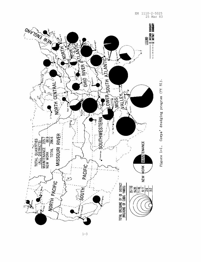
navigation. The Corp's annual dredging workload is approximately 287
million cu yd of material, including both maintenance and new work. The
Corps accomplishes the majority (70 percent in FY 81) of its annualdredging workload by contracting privately owned equipment under
competitive bidding procedures; it performs the remaining work using
hired labor to operate Corps-owned dredges (item 5). An overview of the
Corps' dredging program is shown in figure l-l.
1-2
EM 1110-2-502525 Mar 83
1-3
EM 1110-2-502525 Mar 83
1-6. Considerations Associated with Dredging and Dredged Material Disposal.
Some considerations associated with dredging and dredged material disposal
are as follows:
a. Selection of proper dredge plant for a given project.
b. Determining whether or not there will be dredging of contaminated
material.
c. Adequate disposal facilities.
d. Long-term planning for maintenance dredging projects.
e. Characterization of sediments to be dredged to support an engineer-
ing design of confined disposal areas.
f. Determining the levels of suspended solids from disposal areas and
dredge operations.
g. Disposal of contaminated sediments.
h. Disposal in remote areas.
i. Control of dredging operation to ensure environmental protection.
j. Containment area management for maximizing storage capacity.
1-4

EM 1110-2-502525 Mar 83
CHAPTER 2
DESIGN CONSIDERATIONS
2-1. General. A dredging and dredged material disposal operation requires
consideration of both short- and long-term management objectives. The primary
short-term objective of a dredging project is to construct or maintain
channels for existing navigation needs but not necessarily to authorized
project dimensions. This should be accomplished using the most technically
satisfactory, environmentally compatible, and economically feasible dredging
and dredged material disposal procedures. Long-term objectives concern the
management and operation of disposal areas to ensure their long-term use.
This chapter outlines the design consideration usually needed to meet the
objectives of a dredging project.
2-2. Preliminary Data Collection. In order to gather the data required for a
dredging and dredged material disposal project, it is necessary to do the
following:
a. Analyze dredging location and quantities to be dredged, consi-
dering future needs.
b. Determine the physical and chemical characteristics of the sediments.
c. Evaluate potential disposal alternatives.
d. Identify pertinent social, environmental, and institutional factors.
e. Evaluate dredge plant requirements.
2-3. Dredging Locations and Quantities.
a. Dredging locations and the quantities of material to be dredged are
two of the most important considerations in planning dredging projects. Sincedisposal of dredged material is usually the major dredging problem, it is
essential that long-term projections be made for disposal requirements of each
project. Records should be kept of quantities dredged and maintenance
interval(s) to forecast future dredging and disposal requirements.
b. Hydrographic surveys are the principal dredged contract management
tool of the Corps. Hydrographic surveys should be made prior to dredging
to determine existing depths within the project area and after dredging
to determine the depths that were attained as a result of the dredging
operation. Each district should have the capability, either in-house or
by contract, to make accurate, timely, and repeatable hydrographic surveys.
To ensure accuracy, quantity calculations must be made from survey data
gathered in a timely manner using proper equipment and based upon precisely
established horizontal and vertical controls. Direct tide level readings
must be made at the site of the work to eliminate gross errors in quantity
calculations. Quantity measurement methods must be fully consistent
2-1

EM 1110-2-502525 Mar 83
between work per formed by contract and work per formed by hired labor.
2-4. Physical Properties of Sediments. In planning any dredging operation
which constitutes a specialized problem in earthmoving or excavation, it is
essential that field measurements and computations be made to determine the
location, characteristics, and quantities of material to be removed. The
characteristics of the dredged material determine dredge plant and, to some
extent, disposal requirements. Refer to Chapter 4 for specific
characterization tests required for evaluation and design of disposal
alternatives for dredged material.
a. Sampling. Sediment samples should be taken of the material above the
depth to which removal will be credited. This should be done concurrent with
the pre-dredge survey. For maintenance dredging of a recurring nature,
samples will be taken before each dredging until the characteristics of the
sediments are well known. For subsequent dredging, a small number of samples
will be taken to identify and changes in sediment characteristics. Normally
the sediment sampling depth will be the authorized project depth plus an
allowable tolerance (usually 2 ft) to compensate for the inherent inaccuracies
of the dredging process. The number of sediment samples taken should be
sufficient to obtain accurate information regarding the characteristics of the
material to be dredged. Samples in soft materials can be obtained by push
tube or grab samplers.
(1) Tube sampling.
(a) A tube sampler is an open-ended tube that is thrust vertically into
the sediment deposit to the depth desired. The sampler is withdrawn from the
deposit with the sample retained within the tube. Differences among tube
samplers relate to tube size, tube wall thickness, type of penetrating nose,
head design including valve, and type of driving force. Tube samplers (alsocalled harpoon samplers) are available with adjustable weights in the range of
from 17 to 77 lb and with fixed weights in excess of 90 lb. The amount of
weight required depends upon deposit texture and required depth of penetration.
(b) The split barrel sample spoon (also known as split-spoon sampler) is
capable of penetrating hard sediments , provided sufficient force is applied to
the driving rods. The sampler is thrust into the deposit by the hammering
force exerted on rods connected to the head. During retrieval, the sample is
retained within the barrel by a flap. The nose and head are separated from
the barrel in order to transfer the sample to a container. Refer to EM
1110-2-1907 for more information on soil sampling.
(2) Grab sampling. A grab sampler consists of a scoop or bucket
container that bites into the soft sediment deposit and encloses the sample.
Grab samplers are used primarily to sample surface materials, with depth of
penetration being 12 in. or less. Grab samplers are easy and inexpensive to
obtain and may be sufficient to characterize sediment for routine maintenancedredging. Grab sampling may indicate relatively homogeneous sediment
composition, segregated pockets or coarse- and fine-grained sediment, and/or
mixtures. If segregated pockets are present, samples should be taken at
2-2

EM 1110-2-502525 Mar 83
a sufficient number of locations in the channel to adequately define spa-
tial variations in the sediment character and quantities of each material.
(3) New work. Samples taken by conventional boring techniques are
normally required for new work dredging. Samples should be taken fromwithin the major zones of spatial variation in sediment type or along the
proposed channel center line at constant spacing to define stratification
within the material to be dredged and to obtain representative samples.
Borings are required for new projects and should be advanced below the depth
of anticipated dredging. The relative density of sands can be determinedby driving a split-spoon sampler and recording the number of blows required
to penetrate each foot of sand. Refer to EM 1110-2-1907 for informationon conventional soil sampling methods and standard split-spoon penetration
tests. Information on the soil above and below the authorized new work
depth is needed to properly design the channel slopes. It is essential toobtain the characteristics of the material to be dredged to preclude deter-
mination of unsuitable dredge plant, unrealistic production and cost esti-mates, etc. Pertinent information regarding sediment samplers is summa-rized in table 2-1.
b. Laboratory Testing. Laboratory tests are required to provide data
for determining the proper dredge plant, evaluating and designing disposalalternatives, designing channel slopes and retention dikes, and estimating
long-term storage capacity for confined disposal areas. The tests dis-
cussed below are to be used to characterize the material to be dredged so
that a proper dredge plant can be selected. Specific tests for evaluationand design of disposal alternatives are discussed in Chapter 4. The re-
quired laboratory tests are essentially standard tests and generally follow
procedures found in EM 1110-2-1906 . The extent of the testing program is
project-dependent: fewer tests are required when dealing with a relatively
homogeneous material and/or when data are available from previous tests and
experience, as is frequently the case in maintenance dredging; for new work
projects and unusual maintenance dredging projects where considerable vari-
ation in sediment properties is apparent from samples, more extensive labo-
ratory testing programs are required. Laboratory tests should always be
performed on representative sediment samples. Tests required on fine-
grained sediments (those of which more than half pass through a No. 40
sieve) include natural water content, plasticity analyses (Atterberg
limits), and specific gravity. The coarse-grained sediments (those of
which more than half are retained on a No. 40 sieve) require only grain
size analyses and in situ density determinations. These tests are de-
scribed below.
(1) Natural water content test. Natural water content refers to the
in situ water content of the sediment. It is used to determine the in situ
void ratio and in situ density of fine-grained sediments. Water content
determinations should be made on representative samples from borings and
grab samples of fine-grained sediment obtained during field investigation.
Fine-grained sediments do not drain rapidly; thus, representative samples
taken from borings and grab samples are considered to represent in situ
water contents. Detailed test procedures for determining the water content
are found in Appendix I of EM 1110-2-1906.
2-3

EM 1110-2-502525 Mar 83
Table 2-1. Summary of Sediment Sampling Equipment
Sampler Weight Remarks
Peterson 39-93 lb Samples 144-in.2
area to a
depth of up to 12 in., de-
pending on sediment texture
Shipek 150 lb Samples 64-in.2
area to a
depth of approximately 4 in.
Ekman
Ponar
Drag Bucket
9 lb Suitable only for very soft
sediments
45-60 lb Samples 81-in.2area to a
depth of less than 12 in.
Ineffective in hard clay
Varies Skims an irregular slice of
sediment surface. Available
in assorted sizes and shapes
Phleger Tube Variable : Shallow core samples may be(gravity
corer)17-77 lb; obtained by self-weight
fixed in penetration and/or pushingexcess of from boat. Depth of pene-
90 lb tration dependent on weight
and sediment texture
Conventional Refer to
Soil Samplers EM 1110-2-1907
Conventional soil samplers
may be employed using barge-
or boat-mounted drilling
equipment. Core samples
attainable to full depth of
dredging
2-4

EM 1110-2-5025
25 Mar 83
(2) Plasticity analyses. Plasticity analyses (Atterberg limits) should
be performed on the separated fine-grained fraction (passing the No. 40 sieve)
of sediment samples. A detailed explanation of the tests required to evaluate
the plasticity of sediments is presented in Appendix III of EM 1110-2-1906.
Samples should be classified according to the Unified Soil Classification
System (USCS) (item 12).
(3) Specific gravity test. Values for the specific gravities of solids
in fine-grained sediments are required for determining void ratios and in situ
densities. Procedures for conducting the specific gravity test are given in
Appendix IV of EM 1110-2-1906.
(4) Grain size analyses. Grain size analyses are required only on the
coarse-grained fraction of samples. Grain size analyses should follow the
procedures contained in Appendix V of EM 1110-2-1906.
c. In situ density. In situ density is used to evaluate dredgability to
sediments and aid in equipment selection, to estimate production rates, and to
estimate volume required for storage in confined disposal areas. In situ
density can be estimated from field investigations of sediments or from
laboratory test data using geotechnical engineering formulas. Refer to
Appendix II of EM 1110-2-1906 for guidance in estimating in situ density from
laboratory tests. For sand sediments, relative density has a decisive
influence on the selection of equipment for dredging. The relative density of
sands can be estimated from standard split-spoon penetration tests (para
2-4a). Table 2-2 presents estimates of relative density of sands based on
standard penetration tests. Where no field tests are performed on coarse-
grained materials (i.e. sand, gravel, etc., ) the material in its densest state
based on laboratory tests will be considered comparable to its in situ
condition.
Table 2-2. Relative Density of Sands According to Results
of Standard Penetration Tests
No. of Blows/ft Relative Density
0-4
4-10
10-30
30-50
Over 50
Very loose
Loose
Medium
Dense
Very dense
2-5. Selection of Dredging Equipment. Most Corps dredging is performed by
private industry under contract, and the specifications should not be
written such that competitive bidding is restricted. However, in certain
situations limitations may be placed on the equipment to be used to mini-
mize the environmental impact of the dredging and disposal operation. In
cases where available upland containment areas are small, the size of the
dredge should be restricted to minimize stress on the containment area
dikes and to provide adequate retention time for sedimentation to minimize
2-5
EM 1110-2-502525 Mar 83
excessive suspended solids in the weir effluent. Environmentalprotection is adequate justification for carefully controlling the
selection and use of dredging equipment. The dredging of contaminatedsediments requires careful assessment of the dredging operation. The
information presented in Chapters 3 and 4 will provide guidance for
proper equipment selection based on the materials to be dredged, dredging
environment, contamination level of sediments, transport and disposal
requirements, and production requirements.
2-6. Disposal Alternatives. The major considerations in selecting
disposal alternatives are the environmental impact and the economics of
the disposal operation. Much of the recent knowledge concerning dredged
material disposal was gained as a result of the Dredged Material Research
Program (DMRP) conducted by the U.S. Army Engineer Waterways Experiment
Station (WES) and reported in WES Technical Reports. The majorobjectives of the DMRP were to provide definitive information on the
environmental impact of dredging and dredged material disposal operations
and to develop new or improved dredged material disposal practices. The
research was conducted on a national basis, excluding no major types ofdredging activity or region or environmental setting. It producedmethods for evaluating the physical, chemical, and biological impacts of
a variety of disposal alternatives in water, on land, or in wetland
areas, as well as tested, viable, cost-effective methods and guidelines
for reducing the impacts of conventional disposal alternatives. Summaryreports produced under this program are listed in para 1-3, and a
detailed discussion of disposal alternatives is presented in Chapter 4.
Two fundamental conclusions were drawn from the results of the DMRP
concerning disposal of dredged material: (1) no single disposal
alternative can be presumed most suitable for a region, a type of dredgedmaterial, or a group of projects before it has been tested, and (2)
environmental considerations make necessary long-range regional planning
for lasting, effective solutions to disposal concerns. There is noinherent effect or characteristic of a disposal alternative that can rule
it out of consideration from an environmental standpoint before specific
on-site evaluation. This holds true for open-water disposal, confined
upland disposal, habitat development, or any other alternative.
Case-by-Case project evaluations are time-consumig and expensive and may
seriously complicate advanced planning and funding requests.
Nevertheless, from a technical point of view, situations can be
envisioned where tens of millions of dollars may have been or could be
spent for disposal alternatives that contribute to adverse environmental
effects rather than reduce them. Also, easily obtained beneficial
impacts should not be overlooked. No category of disposal alternative is
without environmental risk or offers the soundest environmental
protection or reflects the best management practice; therefore, all
disposal alternatives should be fully investigated during the planning
process and treated on an equal basis until a final decision can be made
based on all available facts. It is hypothesized that all alternativescould be considered to dispose of even the most highly contaminated
dredged material if a plan could be devised for management that was
adequate and legally acceptable under domestic regulations and
international treaty.
2-7. Long-Range Studies. Dredging and disposal activities cannot be
2-6

EM 1110-2-5025
25 Mar 83
designed independently for each of several projects in a given area. While
each project may require different specific solutions, the interrelation-
ships among them must be determined. Thought must also be given to chang-
ing particular dredging techniques and disposal alternatives as conditions
change. Long-range regional dredging and disposal management plans not
only offer greater opportunities for environmental protection and effective
use of dredging equipment at reduced project cost, but they also meet with
greater public acceptance once they are agreed upon. Long-range plans mustreflect sound engineering design, consider and minimize any adverse environ-mental impacts, and be operationally implementable.
2-7

EM 1110-2-502525 Mar 83
CHAPTER 3
DREDGING EQUIPMENT AND TECHNIQUES
3-1. Purpose. This chapter includes a description of the dredging equip-
ment and techniques used in dredging activities in the United States and
presents advantages and limitations for each type of dredge. Guidance is
provided for selection of the best dredging equipment and techniques for a
proposed dredging project to aid in planning and design.
3-2. Factors Determining Equipment Selection.
a. The types of equipment used, by both the Corps and private in-
dustry, and the average annual amount of dredging associated with each type
are shown in Figure 3-1. The dredging methods employed by the Corps varyconsiderably throughout the United States. Principal types of dredges in-
clude hydraulic pipeline types (cutterhead, dustpan, plain suction, and
sidecaster), hopper dredges, and clamshell dredge. The category of "other"
dredges in Figure 3-1 includes dipper, ladder, and special purpose dredges.However, there are basically only three mechanisms by which dredging is
actually accomplished:
(1) Suction dredging. Removal of loose materials by dustpans,
hoppers, hydraulic pipeline plain suction, and sidecasters, usually for
maintenance dredging projects.
(2) Mechanical dredging. Removal of loose or hard, compacted mate-
rials by clamshell, dipper, or ladder dredges, either for maintenance or
new work projects.
(3) A combination of suction and mechanical dredging. Removal. of
loose or hard, compacted materials by cutterheads, either for maintenance
or new work projects.
b. Selection of dredging equipment and method used to perform the
dredging will depend on the following factors:
(1) Physical characteristics of material to be dredged.
(2) Quantities of material to be dredged.
(3) Dredging depth.
(4) Distance to disposal area.
(5) Physical environment of and between the dredging and disposal
areas.
(6) Contamination level of sediments.
(7) Method of disposal.
3-1

EM 1110-2-502525 Mar 83
3-2

EM 1110-2-502525 Mar 83
(8) Production required.
(9) Type of dredges available.
3-3. Hopper Dredges.
a. General. Hopper dredges are self-propelled seagoing ships of from180 to 550 ft in length, with the molded hulls and lines of ocean vessels
(fig. 3-2). They are equipped with propulsion machinery, sediment con-
tainers (hoppers), dredge pumps, and other special equipment required toperform their essential function of removing material from a channel bottom
or ocean bed. Hopper dredges have propulsion power adequate for requiredfree-running speed and dredging against strong currents and excellent maneu-
verability for safe and effective work in rough, open seas. Dredged mate-rial is raised by dredge pumps through dragarms connected to drags in
contact with the channel bottom and discharged into hoppers built in the
vessel. Hopper dredges are classified according to hopper capacity: large-class dredges have hopper capacities of 6000 cu yd or greater, medium-class
hopper dredges have hopper capacities of 2000 to 6000 cu yd, and small-
class hopper dredges have hopper capacities of from less than 2000 to
500 cu yd. During dredging operations, hopper dredges travel at a groundspeed of from 2 to 3 mph and can dredge in depths from about 10 to over
80 ft. They are equipped with twin propellers and twin rudders to provide
the required maneuverability. Table 3-1 gives available specifications for
all vessels in the Corps hopper dredge fleet.
b. Description of Operation.
(1) General. Operation of a seagoing hopper dredge involves greater
effort than that required for an ordinary ocean cargo vessel, because not
only the needs of navigation of a self-propelled vessel but also the needs
associated with its dredging purposes must be satisfied. Dredging is ac-
complished by progressive traverses over the area to be dredged. Hopper
dredges are equipped with large centrifugal pumps similar to those employed
by other hydraulic dredges. Suction pipes (dragarms) are hinged on each
side of the vessel with the intake (drag) extending downward toward the
stern of the vessel. The drag is moved along the channel bottom as the
vessel moves forward at speeds up to 3 mph. The dredged material is sucked
up the pipe and deposited and stored in the hoppers of the vessel. Once
fully loaded, hopper dredges move to the disposal site to unload before re-
suming dredging. Unloading is accomplished either by opening doors in the
bottoms of the hoppers and allowing the dredged material to sink to the
open-water disposal site or by pumping the dredged material to upland dis-
posal sites. Because of the limitations on open-water disposal, most
hopper dredges have direct pumpout capability for disposal in upland con-
fined sites. Before there were environmental restrictions, hopper dredges
were operated with the primary objective of obtaining the maximum economic
load; i.e., removing the maximum quantity of material from the channel
prism in the shortest pumping time during a day's operation.
(2) Hopper dredging is accomplished by three methods: (a) pumping
past overflow, (b) agitation dredging, and (c) pumping to overflow. The
3-3

EM 1110-2-502525 Mar 83
HOPPERS
Figure 3-2. Self-propelled seagoing hopper dredge.
3-4

EM 1110-2-502525 Mar 83
3-5

EM 1110-2-5025
25 Mar 83
use of these methods is controlled to varying degrees by environmental
legislation and the water quality certification permits required by the
various states in which dredging is being accomplished. The environmentaleffects of these methods must be assessed on a project-by-project basis.
If the material being dredged is clean sand, the percentage of solids in
the overflow will be small and economic loading may be achieved by pumping
past overflow. When contaminated sediments are to be dredged and adverseenvironmental effects have been identified , pumping past overflow is notrecommended. In such cases, other types of dredges may be more suitablefor removing the contaminated sediments from the channel prism. If hopperdredges are not allowed to pump past overflow in sediments that have good
settling properties, the cost of dredging increases. The settling proper-ties of silt and clay sediments may be such that only a minimal load in-
crease would be achieved by pumping past overflow. Economic loading, i.e.the pumping time required for maximum production of the hopper dredge,
should be determined for each project. These determinations, along withenvironmental considerations, should be used to establish the operationprocedures for the hopper dredge.
(3) Agitation dredging. Agitation dredging is a process which inten-
tionally discharges overboard large quantities of fine-grained dredged ma-terial by pumping past overflow, under the assumption that a major portion
of the sediments passing through the weir overflow will be transported and
permanently deposited outside the channel prism by tidal, river, or littoral
currents. Agitation dredging should be used only when the sediments dredgedhave poor settling properties, when there are currents in the surrounding
water to carry the sediments from the channel prism, and when the risk toenvironmental resources is low. Favorable conditions may exist at a par-ticular project only at certain times of the day, such as at ebb tides, or
only at such periods when the streamflow is high. To use agitation dredg-
ing effectively requires extensive studies of the project conditions and
definitive environmental assessments of the effects. Agitation dredging
should not be performed while operating in slack water or when prevailing
currents permit redeposit of substantial quantities of the dredged material
in the project area or in any other area where future excavation may be
required. Refer to para 3-12 for more information on this topic.
(4) Refer to ER 1125-2-312 for instructions for hopper dredge
operations.
c. Application. Hopper dredges are used mainly for maintenance dredg-
ing in exposed harbors and shipping channels where traffic and operating
conditions rule out the use of stationary dredges. The materials excavated
by hopper dredges cover a wide range of types, but the hopper dredge is most
effective in the removal of material which forms shoals after the initial
dredging is completed. While specifically designed drags are available for
use in raking and breaking up hard materials, hopper dredges are most effi-
cient in excavating loose, unconsolidated materials. At times, hopper
dredges must operate under hazardous conditions caused by fog, rough seas,
and heavy traffic encountered in congested harbors.
d. Advantages. Because of the hopper dredge’s design and method of
3-6

EM 1110-2-502525 Mar 83
operation, the self-propelled seagoing hopper dredge has the following ad-
vantages over other types of dredges for many types of projects:
(1) It is the only type of dredge that can work effectively, safely,
and economically in rough, open water.
(2) It can move quickly and economically to the dredging projectunder its own power.
(3) Its operation does not interfere with or obstruct traffic.
(4) Its method of operation produces usable channel improvement almost
as soon as work begins. A hopper dredge usually traverses the entire lengthof the problem shoal, excavating a shallow cut during each passage and in-creasing channel depth as work progresses.
(5) The hopper dredge may be the most economical type of dredge to
use where disposal areas are not available within economic pumping dis-
tances of the hydraulic pipeline dredge.
e. Limitations. The hopper dredge is a seagoing self-propelled vesseldesigned for specific dredging projects. The following limitations are as-sociated with this dredge:
(1) Its deep draft precludes use in shallow waters, including barge
channels.
(2) It cannot dredge continuously. The normal operation involves
loading, transporting material to the dump site, unloading, and returning
to the dredging site.
(3) The hopper dredge excavates with less precision than other types
of dredges.
(4) Its economic load is reduced when dredging contaminated sediments
since pumping past overflow is generally prohibited under these conditions
and low-density material must be transported to and pumped into upland dis-
posal areas.
(5) It has difficulty dredging side banks of hardpacked sand.
(6) The hopper dredge cannot dredge effectively around piers and
other structures.
(7) Consolidated clay material cannot be economically dredged with
the hopper dredge.
3-4. Cutterhead Dredges.
a. General. The hydraulic pipeline cutterhead suction dredge is the
most commonly used dredging vessel and is generally the most efficient and
versatile (fig. 3-3). It performs the major portion of the dredging
3-7

EM 1110-2-502525 Mar 83
DISCHARGE LINE
CUTTERHEAD
Figure 3-3. Hydraulic pipeline cutterhead dredge.
3-8
EM 1110-2-5025
25 Mar 83
workload in the United States. Because it is equipped with a rotating
cutter apparatus surrounding the intake end of the suction pipe, it can ef-
ficiently dig and pump all types of alluvial materials and compacted de-
posits, such as clay and hardpan. This dredge has the capability of pump-ing dredged material long distances to upland disposal areas. Slurries of
10 to 20 percent solids (by dry weight) are typical, depending upon the
material being dredged, dredging depth, horsepower of dredge pumps, and
pumping distance to disposal area. If no other data are available, a pipe-line discharge concentration of 13 percent by dry weight (145 ppt) should
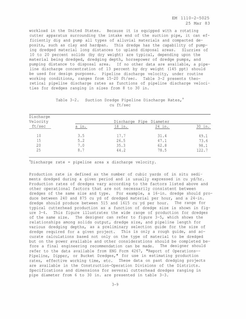
be used for design purposes. Pipeline discharge velocity, under routineworking conditions, ranges from 15-20 ft/sec. Table 3-2 presents theo-retical pipeline discharge rates as functions of pipeline discharge veloci-
ties for dredges ranging in sizes from 8 to 30 in.
Table 3-2. Suction Dredge Pipeline Discharge Rates,a
cu ft/sec
Discharge
Velocity
ft/sec a in.
Discharge Pipe Diameter
18 in. 24 in. 30 in.
10 3.5 17.7 31.4 49.115 5.2 26.5 47.1 73.620 7.0 35.3 62.8 98.125 8.7 44.2 78.5 122.7
aDischarge rate = pipeline area x discharge velocity.
Production rate is defined as the number of cubic yards of in situ sedi-
ments dredged during a given period and is usually expressed in cu yd/hr.
Production rates of dredges vary according to the factors listed above and
other operational factors that are not necessarily consistent between
dredges of the same size and type. For example, a 16-in. dredge should pro-
duce between 240 and 875 cu yd of dredged material per hour, and a 24-in.
dredge should produce between 515 and 1615 cu yd per hour. The range for
typical cutterhead production as a function of dredge size is shown in fig-
ure 3-4. This figure illustrates the wide range of production for dredges
of the same size. The designer can refer to figure 3-5, which shows the
relationships among solids output, dredge size, and pipeline length for
various dredging depths, as a preliminary selection guide for the size of
dredge required for a given project. This is only a rough guide, and ac-
curate calculations based not only on the type of material to be dredged
but on the power available and other considerations should be completed be-
fore a final engineering recommendation can be made. The designer should
refer to the data available from ENG Form 4267, "Report of Operations--
Pipeline, Dipper, or Bucket Dredges," for use in estimating production
rates, effective working time, etc. These data on past dredging projects
are available in the Construction-Operation Divisions of the Districts.
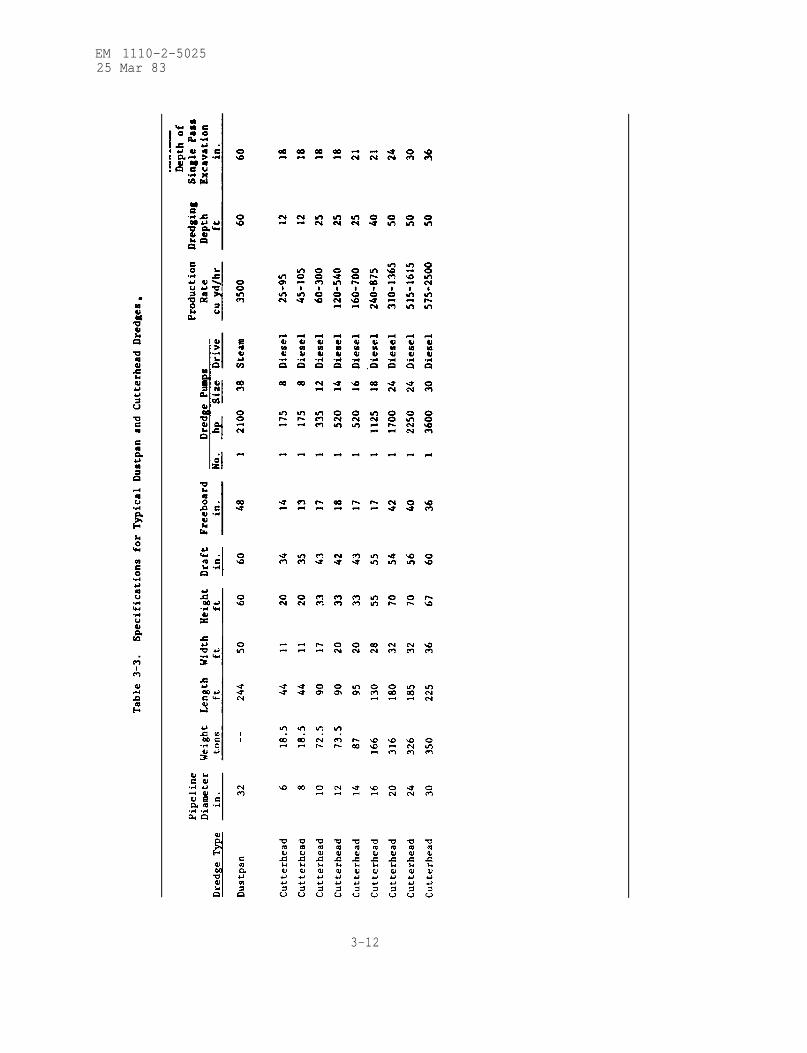
Specifications and dimensions for several cutterhead dredges ranging in
pipe diameter from 6 to 30 in. are presented in table 3-3.
3-9

EM 1110-2-502525 Mar 83
DREDGE SIZE. IN.
Figure 3-4. Typical cutterhead dredge production according to
dredge size.
3-10

EM 1110-2-502525 Mar 83
Figure 3-5. Relationships among solids output, dredge size, and
pipeline length for various dredging depths- (WES TR DS-78-10 )
3-11
EM 1110-2-502525 Mar 83
3-12

EM 1110-2-502525 Mar 83
b. Description of Operation. The cutterhead dredge is generally
equipped with two stern spuds used to hold the dredge in working position
and to advance the dredge into the cut or excavating area. During opera-
tion, the cutterhead dredge swings from side to side alternately using the
port and starboard spuds as a pivot, as shown in figure 3-6. Cables at-
tached to anchors on each side of the dredge control lateral movement. For-
ward movement is achieved by lowering the starboard spud after the port
swing is made and then raising the port spud. The dredge is then swung
back to the starboard side of the cut centerline. The port spud is lowered
and the starboard spud lifted to advance the dredge. The excavated mate-
rial may be disposed of in open water or in confined disposal areas located
upland or in the water. In the case of open-water disposal, only a float-
ing discharge pipeline, made up of sections of pipe mounted on pontoons and
held in place by anchors, is required. Additional sections of shore pipe-
line are required when upland disposal is used. In addition, the excavated
materials may be placed in hopper barges for disposal in open water or in
confined areas that are remote from the dredging area. In cutterhead dredg-
ing, the pipeline transport distances usually range up to about 3 miles.
For commercial land reclamation or fill operations, transport distances are
generally longer, with pipeline lengths reaching as far as 15 miles, for
which the use of multiple booster pumps is necessary.
6‘ANCHOR ANCHOR
I ,0 .
I ! /
3WN)
Figure 3-6. Operation of a cutterhead dredge (viewed
from above).
3-13

EM 1110-2-5025
25 Mar 83
c. Application. Although the cutterhead dredge was developed toloosen up densely packed deposits and eventually cut through soft rock, it
can excavate a wide range of materials including clay, silt, sand, and
gravel. The cutterhead, however, is not needed in maintenance dredging ofmost materials consisting of clay, silt, and fine sand because in these ma-terials, rotation of the cutterhead produces a turbidity cloud and in-creases the potential for adverse environmental impacts. Common practiceis to use the cutterhead whether it is needed or not. When the cutterheadis removed, cutterhead dredges become in effect plain suction dredges. Thecutterhead dredge is suitable for maintaining harbors, canals, and outlet
channels where wave heights are not excessive. A cutterhead dredge de-signed to operate in calm water will not operate offshore in waves over
2-3 ft in height; the cutterhead will be forced into the sediment by waveaction creating excessive shock loads on the ladder. However, a cutterheaddredge designed to operate offshore can operate in waves up to about 6 ft.
d. Advantages. The cutterhead dredge is the most widely used dredgein the United States because of the following advantages:
(1) Cutterhead dredges are used on new work and maintenance projects
and are capable of excavating most types of material and pumping it through
pipelines for long distances to upland disposal sites.
(2) The cutterhead operates on an almost continuous dredging cycle,
resulting in maximum economy and efficiency.
(3) The larger and more powerful machines are able to dredge rocklikeformations such as coral and the softer types of basalt and limestone with-
out blasting.
e. Limitations. The limitations on cutterhead dredges are as follows:
(1) The cutterhead dredges available in the United States have
limited capability for working in open-water areas without endangering per-
sonnel and equipment. The dredging ladder on which the cutterhead and suc-
tion pipe are mounted is rigidly attached to the dredge; this causes opera-
tional problems in areas with high waves.
(2) The conventional cutterhead dredges are not self-propelled. They
require the mobilization of large towboats in order to move between dredg-
ing locations.
(3) The cutterhead dredge has problems removing medium and coarse
sand in maintaining open channels in rivers with rapid currents. It is dif-
ficult to hold the dredge in position when working upstream against the
river currents since the working spud often slips due to scouring effects.
When the dredge works downstream, the material that is loosened by the cut-
terhead is not pulled into the suction intake of the cutterhead. This
causes a sandroll, or berm, of sandy material to form ahead of the dredge.
(4) The pipeline from the cutterhead dredge can cause navigation
problems in small, busy waterways and harbors.
3-14

EM 1110-2-502525 Mar 83
3-5. Dustpan Dredge.
a. General. The dustpan dredge is a hydraulic suction dredge that
uses a widely flared dredging head along which are mounted pressure water
jets (fig. 3-7). The jets loosen and agitate the sediments which are then
captured in the dustpan head as the dredge itself is winched forward intothe excavation. This type of dredge was developed by the Corps of Engi-
neers to maintain navigation channels in uncontrolled rivers with bedloads
consisting primarily of sand and gravel. The first dustpan dredge was de-
veloped to maintain navigation on the Mississippi River during low river
stages. A dredge was needed that could operate in shallow water and be
large enough to excavate the navigation channel in a reasonably short time.
The dustpan dredge operates with a low-head, high-capacity centrifugal pump
since the material has to be raised only a few feet above the water surface
and pumped a short distance. The dredged material is normally discharged
into open water adjacent to the navigation channel through a pipeline
usually only 800 to 1000 ft long.
b. Description of Operation. The dustpan dredge maintains navigation
channels by making a series of parallel cuts through the shoal areas until
the authorized widths and depths are achieved. Typical operation pro-
cedures for the dustpan dredge are as follows:
(1) The dredge moves to a point about 500 ft upstream of the upper
limit of the dredging area and the hauling anchors are set. Two anchors
are used, as shown in Figure 3-8. The hauling winch cables attached to the
anchors are crossed to provide better maneuverability and control of the
vessel while operating in the channel prism.
(2) The dredge is then moved downstream to the desired location. The
suction head is lowered to the required depth, dredge pump and water jet
pumps are turned on, and the dredging commences. The dredge is moved for-
ward by the hauling cables. The rate of movement depends on the materials
being dredged, depth of dredging, currents, and wind. In shallow cuts, the
advance may be as rapid as 800 ft/hr.
(3) When the upstream end of the cut is reached, the suction head is
raised and the dredge is moved back downstream to make a parallel cut. This
operation is repeated until the desired dredging widths and depths are
achieved.
(4) The suction head may have to be lowered or raised if obstacles
such as boulders, logs, or tree stumps are encountered. Experience with
dustpan dredges indicates that the best results are obtained when the
height of the cut face does not exceed 6 ft in depth.
(5) The dr de ge is moved outside the channel to let waterborne traffic
pass through the area simply by raising the suction head and slacking off
on one of the hauling winch cables. The propelling engines can be used to
assist in maneuvering the dredge clear of the channel. The vessel is held
in position by lowering the suction head or by lowering a spud.
3-15

EM 1110-2-502525 Mar 83
Figure 3-7. Dustpan dredge.
3-16
EM 1110-2-502525 Mar 83
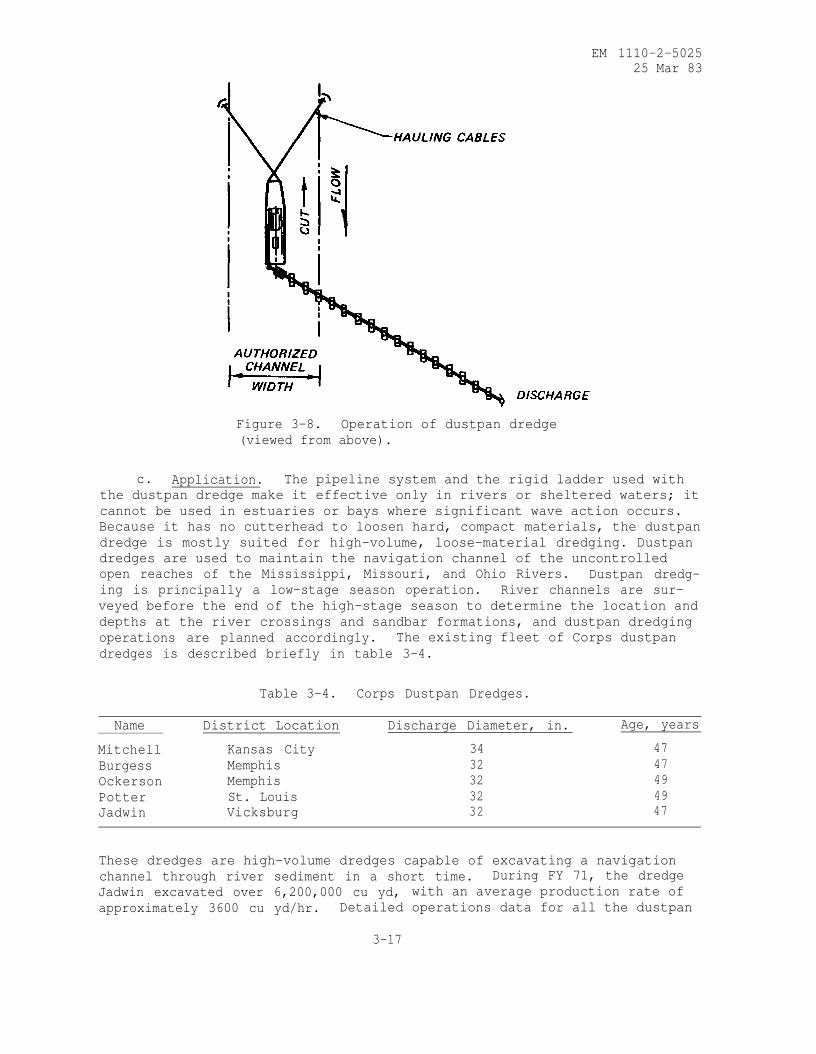
Figure 3-8. Operation of dustpan dredge
(viewed from above).
c. Application. The pipeline system and the rigid ladder used with
the dustpan dredge make it effective only in rivers or sheltered waters; it
cannot be used in estuaries or bays where significant wave action occurs.
Because it has no cutterhead to loosen hard, compact materials, the dustpan
dredge is mostly suited for high-volume, loose-material dredging. Dustpan
dredges are used to maintain the navigation channel of the uncontrolled
open reaches of the Mississippi, Missouri, and Ohio Rivers. Dustpan dredg-
ing is principally a low-stage season operation. River channels are sur-
veyed before the end of the high-stage season to determine the location and
depths at the river crossings and sandbar formations, and dustpan dredging
operations are planned accordingly. The existing fleet of Corps dustpan
dredges is described briefly in table 3-4.
Table 3-4. Corps Dustpan Dredges.
Name District Location Discharge Diameter, in. Age, years
Mitchell Kansas City 34 47
Burgess Memphis 32 47
Ockerson Memphis 32 49
Potter St. Louis 32 49
Jadwin Vicksburg 32 47
These dredges are high-volume dredges capable of excavating a navigation
channel through river sediment in a short time. During FY 71, the dredge
Jadwin excavated over 6,200,000 cu yd, with an average production rate of
approximately 3600 cu yd/hr. Detailed operations data for all the dustpan
3-17
EM 1110-2-502525 Mar 83
dredges are reported on ENG Form 4267, "Report of Operations--Pipeline,
Dipper, or Bucket Dredges." Refer to table 3-3 for specifications for a
typical dustpan dredge.
d. Advantages. The dustpan dredge is self-propelled, which enables it
to move rapidly over long distances to work at locations where emergenciesoccur. The attendant plant and pipeline are designed for quick assembly so
that work can be started a few hours after arrival at the work site. Thedustpan dredge can move rapidly out of the channel to allow traffic to pass
and can resume work immediately. The high production rate and design ofthe dustpan dredge make it possible to rapidly remove sandbar formations
and deposits from river crossings so that navigation channels can be main-
tained with a minimum of interruption to waterborne traffic.
e. Limitations. The dustpan dredge was designed for a specific pur-
pose, and for this reason there are certain limitations to its use in other
dredging environments. It can dredge only loose materials such as sandsand gravels and only in rivers or sheltered waters where little wave actionmay be expected. The dustpan dredge is not particularly well suited for
transporting dredged material long distances to upland disposal sites; pump-
ing distances are limited to about 1000 ft without the use of booster pumps.
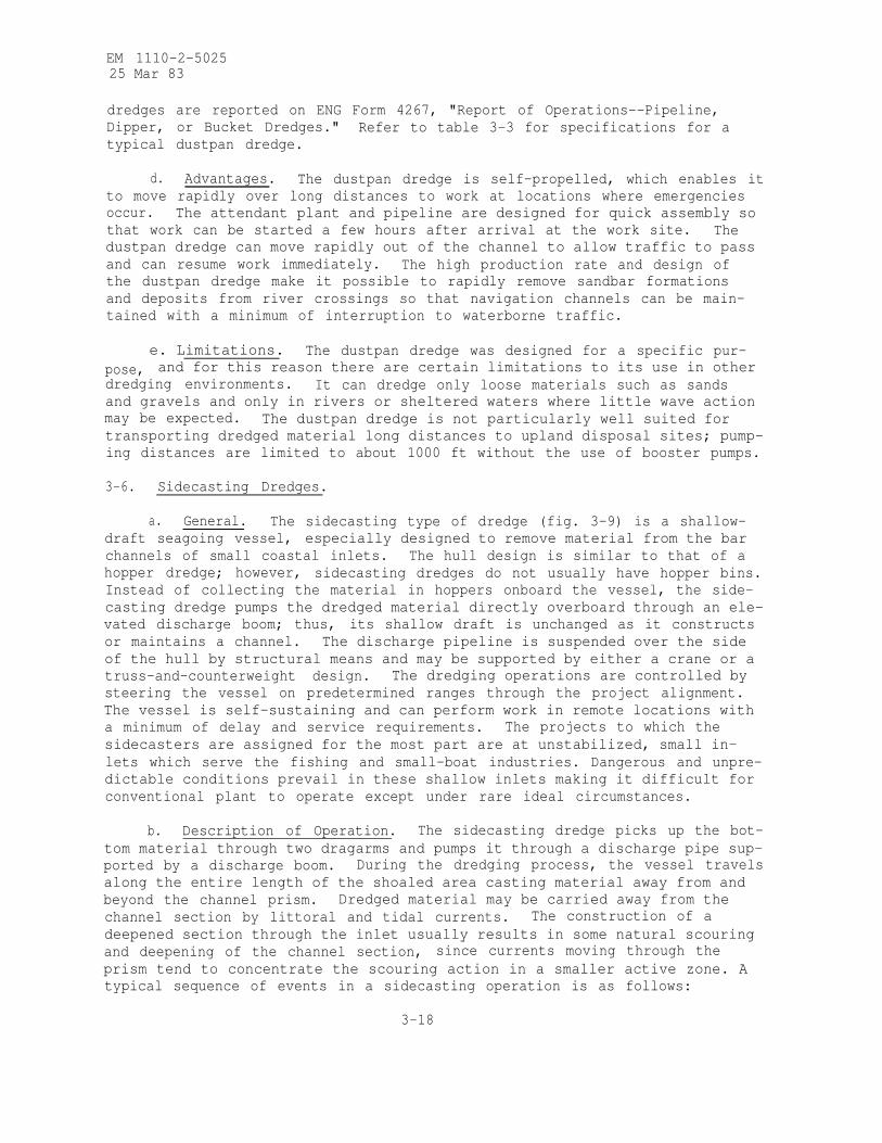
3-6. Sidecasting Dredges.
a. General. The sidecasting type of dredge (fig. 3-9) is a shallow-
draft seagoing vessel, especially designed to remove material from the bar
channels of small coastal inlets. The hull design is similar to that of a
hopper dredge; however, sidecasting dredges do not usually have hopper bins.
Instead of collecting the material in hoppers onboard the vessel, the side-
casting dredge pumps the dredged material directly overboard through an ele-
vated discharge boom; thus, its shallow draft is unchanged as it constructs
or maintains a channel. The discharge pipeline is suspended over the side
of the hull by structural means and may be supported by either a crane or a
truss-and-counterweight design. The dredging operations are controlled by
steering the vessel on predetermined ranges through the project alignment.
The vessel is self-sustaining and can perform work in remote locations with
a minimum of delay and service requirements. The projects to which the
sidecasters are assigned for the most part are at unstabilized, small in-
lets which serve the fishing and small-boat industries. Dangerous and unpre-
dictable conditions prevail in these shallow inlets making it difficult for
conventional plant to operate except under rare ideal circumstances.
b. Description of Operation. The sidecasting dredge picks up the bot-
tom material through two dragarms and pumps it through a discharge pipe sup-
ported by a discharge boom. During the dredging process, the vessel travels
along the entire length of the shoaled area casting material away from and
beyond the channel prism. Dredged material may be carried away from the
channel section by littoral and tidal currents. The construction of a
deepened section through the inlet usually results in some natural scouring
and deepening of the channel section, since currents moving through the
prism tend to concentrate the scouring action in a smaller active zone. A
typical sequence of events in a sidecasting operation is as follows:
3-18

EM 1110-2-502525 Mar 83
Figure 3-9. Sidecasting dredge.
3-19
EM 1110-2-502535 Mar 83
(1) The dredge moves to the work site.
(2) The dragarms are lowered to the desired depth.
(3) The pumps are started to take the material from the channel bot-
tom and pump it through the discharge boom as the dredge moves along a des-
ignated line in the channel prism.
(4) If adequate depths are not available across the bar during low
tide levels, dredging must be started during higher tide levels. Under
these conditions, the cuts are confined to a narrow channel width toquickly attain the flotation depth necessary for dredging to be continued
during the low tidal periods.
(5) The dredge continues to move back and forth across the bar until
the channel dimensions are restored.
(6) The discharge can be placed on either side of the dredge by rotat-
ing the discharge boom from one side of the hull to the other.
c. Application. The Corps of Engineers developed the shallow-draftsidecasting dredge for use in places too shallow for hopper dredges and too
rough for pipeline dredges. The types of materials that can be excavatedwith the sidecasting dredge are the same as for the hopper dredges
(para 3-3c).__
d. Advantages. The sidecasting type of dredge, being self-propelled,can rapidly move from one project location to another on short notice and
can immediately go to work once at the site. Therefore, a sidecastingdredge can maintain a number of projects located great distances from each
other along the coastline.
e. Limitations. The sidecasting dredge needs flotation depths before
it can begin to work because it dredges while moving over the shoaled area.
Occasionally, a sidecaster will need to alter its schedule to work during
higher tide levels periods only, due to insufficient depths in the shoaled
area. Most areas on the seacoast experience a tidal fluctuation sufficient
to allow even the shallowest shoaled inlets to be reconstructed by a side-
casting type of dredge. A shallow-draft sidecasting dredge cannot move
large volumes of material compared to a hopper dredge, and some of the ma-
terial removed can return to the channel prism due to the effects of tidal
and littoral currents. The sidecasting dredge has only open-water disposal
capability; therefore, it cannot be used for dredging contaminated
sediments.
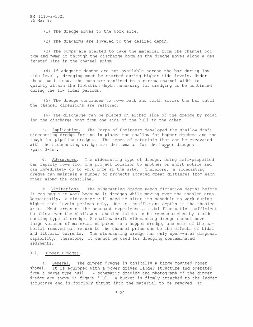
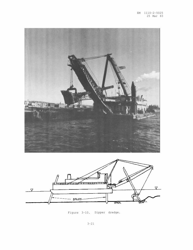
3-7. Dipper Dredges.
a. General. The dipper dredge is basically a barge-mounted power
shovel. It is equipped with a power-driven ladder structure and operated
from a barge-type hull. A schematic drawing and photograph of the dipper
dredge are shown in figure 3-10. A bucket is firmly attached to the ladder
structure and is forcibly thrust into the material to be removed. To
3-20
EM 1110-2-502525 Mar 83
Figure 3-10. Dipper dredge.
3-21
EM 1110-2-5025
25 Mar 83
increase digging power, the dredge barge is moored on powered spuds that
transfer the weight of the forward section of the dredge to the bottom.
Dipper dredges normally have a bucket capacity of 8 to 12 cu yd and a work-ing depth of up to 50 ft. There is a great variability in production rates,
but 30 to 60 cycles per hour is routinely achieved.
b. Description of Operation. The dipper type of dredge is not self-propelled but can move itself during the dredging process by manipulation
of the spuds and the dipper arm. A typical sequence of operation is asfollows :
(1) The dipper dredge, scow barges, and attendant plant are moved tothe work site.
(2) The dredge is moved to the point where work is to start; part of
the weight is placed on the forward spuds to provide stability.
(3) A scow barge is brought alongside and moored into place bywinches and cables on the dipper dredge.
(4) The dredge begins digging and placing the material into the
moored barge.
(5) When all the material within reach of the bucket is removed, the
dredge is moved forward by lifting the forward spuds and maneuvering with
the bucket and stern spud.
(6) The loaded barges are towed to the disposal area and emptied by
bottom dumping if an open-water disposal area is used, or they are unloaded
by mechanical or hydraulic equipment if diked disposal is required.
(7) These procedures are repeated until the dredging operation is
completed.
c. Application. The best use of the dipper dredge is for excavating
hard, compacted materials, rock, or other solid materials after blasting.
Although it can be used to remove most bottom sediments, the violent action
of this type of equipment may cause considerable sediment disturbance and
resuspension during maintenance digging of fine-grained material. In addi-
tion, a significant loss of the fine-grained material will occur from the
bucket during the hoisting process. The dipper dredge is most effective
around bridges, docks, wharves, pipelines, piers, or breakwater structures
because it does not require much area to maneuver; there is little danger
of damaging the structures since the dredging process can be controlled ac-
curately. No provision is made for dredged material containment or trans-
port, so the dipper dredge must work alongside the disposal area or be ac-
companied by disposal barges during the dredging operation.
d. Advantages. The dipper dredge is a rugged machine that can remove
bottom materials consisting of clay, hardpacked sand, glacial till, stone,
or blasted rock material. The power that can be applied directly to the
cutting edge of the bucket makes this type of dredge ideal for the removal
3-22
EM 1110-2-5025
25 Mar 83
of hard and compact materials. It can also be used for removing old piers,
breakwaters, foundations, pilings, roots, stumps, and other obstructions.
The dredge requires less room to maneuver in the work area than most other
types of dredges; the excavation is precisely controlled so that there is
little danger of removing material from the foundation of docks and piers
when dredging is required near these structures. Dipper dredges are fre-
quently used when disposal areas are beyond the pumping distance of pipe-
line dredges, due to the fact that scow barges can transport material over
long distances to the disposal area sites. The dipper type of dredge can
be used effectively in refloating a grounded vessel. Because it can op-
erate with little area for maneuvering, it can dig a shoal out from under
and around a grounded vessel. The dipper dredge type of operation limits
the volume of excess water in the barges as they are loaded. Dipper-
dredged material can be placed in the shallow waters of eroding beaches to
assist in beach nourishment.
e. Limitations. It is difficult to retain soft, semisuspended fine-
grained materials in the buckets of dipper dredges. Scow-type barges are
required to move the material to a disposal area, and the production is
relatively low when compared to the production of cutterhead and dustpan
dredges. The dipper dredge is not recommended for use in dredging con-
taminated sediments.
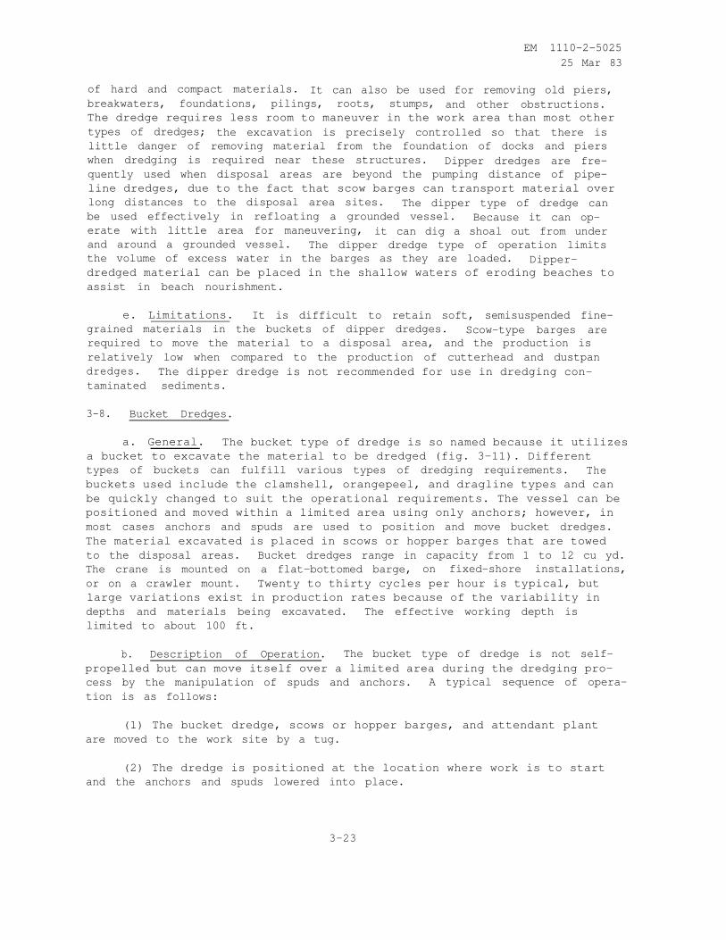
3-8. Bucket Dredges.
a. General. The bucket type of dredge is so named because it utilizes
a bucket to excavate the material to be dredged (fig. 3-11). Different
types of buckets can fulfill various types of dredging requirements. The
buckets used include the clamshell, orangepeel, and dragline types and can
be quickly changed to suit the operational requirements. The vessel can be
positioned and moved within a limited area using only anchors; however, in
most cases anchors and spuds are used to position and move bucket dredges.
The material excavated is placed in scows or hopper barges that are towed
to the disposal areas. Bucket dredges range in capacity from 1 to 12 cu yd.
The crane is mounted on a flat-bottomed barge, on fixed-shore installations,
or on a crawler mount. Twenty to thirty cycles per hour is typical, but
large variations exist in production rates because of the variability in
depths and materials being excavated. The effective working depth is
limited to about 100 ft.
b. Description of Operation. The bucket type of dredge is not self-
propelled but can move itself over a limited area during the dredging pro-
cess by the manipulation of spuds and anchors. A typical sequence of opera-
tion is as follows:
(1) The bucket dredge, scows or hopper barges, and attendant plant
are moved to the work site by a tug.
(2) The dredge is positioned at the location where work is to start
and the anchors and spuds lowered into place.
3-23
EM 1110-2-502525 Mar 83
Figure 3-11. Bucket dredge.
3-24

EM 1110-2-502525 Mar 83
(3) A scow or hopper barge is brought alongside and secured to the
bucket dredge hull.
(4) The dredge begins the digging operation by dropping the bucket in
an open position from a point above the sediment. The bucket falls throughthe water and penetrates into the bottom material. The sides or jaws ofthe bucket are then closed through the use of wire cables operated from the
crane. As the sides of the bucket close, material is sheared from the bot-tom and contained in the bucket compartment. The bucket is raised abovethe water surface and swung to a point over the hopper barge. The materialis then released into the hopper barge by opening the sides of the bucket.
(5) As material is removed from the bottom of the waterway to the de-
sired depth at a given location, the dredge is moved to the next nearby lo-cation by using anchors. If the next dredging area is a significant dis-
tance away, the bucket dredge must be moved by a tug.
(6) The loaded barges are towed to the disposal area by a tug andemptied by bottom dumping if an open water disposal area is used. If adiked disposal area is used, the material must be unloaded using mechnical
or hydraulic equipment.
(7) These procedures are repeated until the dredging operation is
completed.
c. Application. Bucket dredges may be used to excavate most types of
materials except for the most cohesive consolidated sediments and solid
rock. Bucket dredges usually excavate a heaped bucket of material, but dur-
ing hoisting turbulence washes away part of the load. Once the bucketclears the water surface, additional losses may occur through rapid drain-
age of entrapped water and slumping of the material heaped above the rim.
Loss of material is also influenced by the fit and condition of the bucket,
the hoisting speed, and the properties of the sediment. Even under idealconditions, substantial losses of loose and fine sediments will usually
occur. Because of this, special buckets must be used if the bucket dredgeis to be considered for use in dredging contaminated sediments. To minimize
the turbidity generated by a clamshell operation, watertight buckets have
been developed (fig. 3-12). The edges seal when the bucket is closed and
the top is covered to minimize loss of dredged material. Available sizes
range from 2.6 to 26 cu yd. These buckets are best adapted for maintenance
dredging of fine-grained material. A direct comparison of 1.3 cu-yd typi-
cal clamshell and watertight clamshell operations indicates that watertight
buckets generate 30 to 70 percent less turbidity in the water column than
typical buckets. This reduction is probably due primarily to the fact that
leakage of dredged material from watertight buckets is reduced by approxi-
mately 35 percent. The bucket dredge is effective while working near
bridges, docks, wharves, pipelines, piers, or breakwater structures because
it does not require much area to maneuver; there is little danger of dam-
aging the structures because the dredging process can be controlled
accurately.
3-25

EM 1110-2-5025
25 Mar 83
Figure 3-12. Open and closed positions of the watertight bucket.
d. Advantages. The bucket dredge has the same advantages cited for
the dipper dredge, except that its capabilities in blasted rock and compact
materials are somewhat less. The density of material excavated is aboutthe same as the inplace density of the bottom material. Therefore, thevolume of excess water is minimal, which increases the efficiency of opera-tion in the transportation of material from the dredging area to the dis-
posal area.
e. Limitations. The limitations of the bucket type of dredge are the
same as those described for the dipper dredge (para 3-7e).
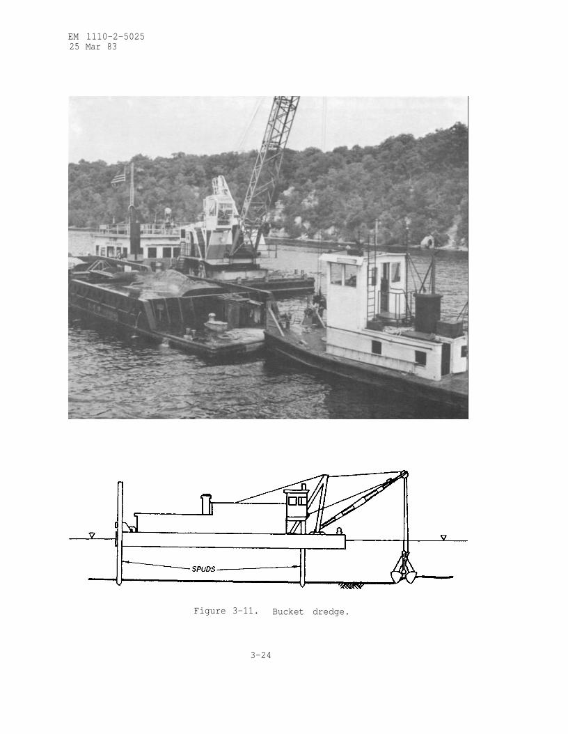
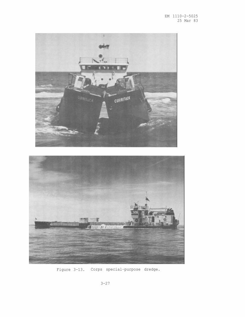
3-9. Special-Purpose Dredge
a. General. The Corps of Engineers Dredge CURRITUCK (fig. 3-13), as-
signed to the Wilmington District, is an example of a special-purpose type
of dredge. Designed to work the same projects as sidecasting dredges, the
CURRITUCK has the additional ability to completely remove material from the
inlet complex and transport it to downdrift eroded beaches. It is a self-
propelled split hull type of vessel, equipped with a self-leveling deck-
house located at the stern, where all controls and machinery are housed.The vessel is hinged above the main deck so that the hull can open from bow
to stern by means of hydraulic cylinders located in compartments forward
and aft of the hopper section. The CURRITUCK has one hopper with a capacity
of 315 cu yd. The hopper section is clearly visible to the operators in
the pilot house, making production monitoring an easy task.
b. Description of Operation. The CURRITUCK operates in much the same
way as a hopper dredge. The operator steers the vessel through the shoal
3-26
EM 1110-2-502525 Mar 83
Figure 3-13. Corps special-purpose dredge.
3-27
EM 1110-2-5025
25 Mar 83
areas of the channel. The dredge pumps, located in the compartments oneach side of the hull, pump material through trailing dragarms into the
hopper section. When an economic load is obtained, the dragarms are liftedfrom the bottom of the waterway and the dredge proceeds to the disposal
area. A major difference between the operation of the CURRITUCK and thatof a conventional hopper dredge is in the method of disposal; the CURRITUCK
is designed to transport and deposit the dredged material close to the surf
zone area.
c. Application. The CURRITUCK provides a sand-bypassing capabilityin addition to improving the condition of navigation channels. TheCURRITUCK excavates material from navigation channels, transports it to
downdrift eroded beaches, and releases it where it is needed to provide
beach nourishment, rather than wasting it offshore. After the material hasbeen deposited in the near-shore coastal areas, the dredge backs away and
returns to the navigation channel.
d. Advantages. The CURRITUCK is an effective dredging tool for usein shallow-draft inlets. All of the dredged material is placed in the lit-toral zone. The CURRITUCK can also be used to supplement sidecastingdredges and to transport dredged materials from inlet channels to the near-
shore areas of eroded beaches.
e. Limitations. The production rate of the CURRITUCK is limited byits small hopper capacity. Therefore, it is not effective on major naviga-tion channels. In addition, when the flotation depths are minimal it isnecessary to use a sidecasting dredge to provide access into the project.
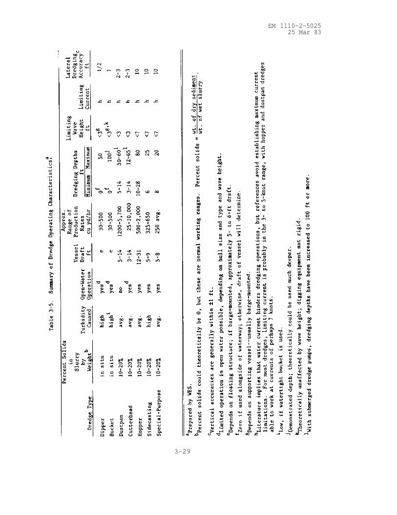
3-10. Summary of Dredge Operating Characteristics. The important operat-
ing characteristics of each dredge presented in the preceding sections are
summarized in table 3-5. In some cases, a wide range of values is given to
account for the various sizes of plants within each class. In other in-
stances, the information provides a qualitative judgement (high, low,
average) of each dredge type’s performance in a given area. Table 3-5
should be helpful in making quick assessments of the suitability of a given
dredge type in a known physical setting.
3-11. Locations of Dredges in the United States. Figure 3-14 shows the
distribution of dredging capability for the Corps and industry in the United
States by region. Congress has determined (Public Law 95-269) that the
Corps will operate a dredging fleet adequate to meet emergency and national
defense requirements at home and abroad. This fleet will be maintained to
technologically modern and efficient standards and will be kept in a fully
operational status. The status of the United States dredging fleet as de-
termined in the Corps of Engineers’ National Dredging Study is comprehen-
sively summarized in a paper of the same title (item 6). A detailed inven-
tory of all dredges in the United States is published annually in World
Dredging and Marine Construction (item 10). The designer can consult this
source for information on the specific types of dredges avail-able in the
proposed project area.
3-28
EM 1110-2-502525 Mar 83
3-29

EM 1110-2-502525 Mar 83
3-30

EM 1110-2-5025
25 Mar 83
3-12. Agitation Dredging Techniques.
a. General. Agitation dredging is the process of removing bottom
material from a selected area by using equipment to raise it in the water
column and allowing currents to carry it from the project area. In the
most detailed study available on agitation dredging techniques, Richardson
(item 7) evaluated past agitation dredging projects and presented guide-
lines and recommendations for using agitation dredging. Two distinctphases are involved in agitation dredging: (1) suspension of bottom sedi-ments by some type of equipment, and (2) transport of the suspended mate-rial by currents. The main purpose of the equipment is to raise bottommaterial in the water column. Natural currents are usually involved intransporting the material from the dredging site, although the natural
currents may be augmented with currents generated by the agitation equip-
ment. Agitation dredging is accomplished by methods such as hopper dredge
agitation, prop-wash, vertical mixers or air bubblers, rakes or dragbeams, and water jets. Based on the work done by Richardson (item 7), onlyhopper dredge, prop-wash, and rake or beam dragging agitation justify moredetailed discussion in this EM.
b. Objectives. The main objective of agitation dredging is the re-
moval of bottom material from a selected area. If the material is
suspended but redeposits shortly in the same area, only agitation (not
agitation dredging) has been accomplished. The decision to use agitation
dredging should be based primarily on the following factors:
(1) Technical feasibility. The equipment to generate the required
level of agitation must be available, and the agitated material must be
carried away from the project area by currents.
(2) Economic feasibility. Agitation dredging must be determined the
most cost-effective method for achieving the desired results; it should not
affect the costs of other dredging projects downstream by increasing
dredging volumes.
(3) Environmental feasibility. Agitation dredging should not cause
unacceptable environmental impacts.
c. Hopper Dredge Agitation.
(1) General. Refer to para 3-3a for a general description of hopper
dredges. In agitation dredging, hopper capacity is of secondary importance
compared with pumping rates, mobility, and overflow provisions.
(2) Description of operation. The general operation of a hopper
dredge is discussed in para 3-3b. In hopper dredge agitation, the conven-
tional dredge-haul-dump operating mode is modified by increasing the
dredging mode and reducing the haul-dump mode. It has been reported that
hopper dredge agitation can allow a project to be maintained with a dredge
which is relatively small compared with the size dredge required for a
conventional dredge-haul-dump operation. Hopper dredge agitation is of
3-31
EM 1110-2-5025
25 Mar 83
two types: (a) intentional agitation produced by hopper overflow; and
(b) auxiliary agitation caused by dragheads and propeller wash. Since the
latter is present in all hopper dredge operations and since it is difficult
to quantify separately from hopper overflow, both types are measured to-
gether when reporting hopper dredge agitation effectiveness.
(3) Application. Agitation hopper dredging can perform the same
maintenance functions as conventional hopper dredging if the following con-
ditions are satisfied: (a) sediments are fine-grained and loosely consoli-
dated, (b) currents are adequate to remove the agitated sediments from the
project area, and (c) no unacceptable environmental impact results fromthe agitation dredging.
(4) Advantages. Because currents, not equipment, transport most ofthe sediment from the project area during agitation hopper dredging, the
following advantages are realized: (a) hopper dredge agitation costs can
be several times less per cubic yard than hopper dredge hauling costs and(b) smaller hopper dredges can be used to maintain certain projects.
(5) Limitations. Hopper dredge agitation should be applied only to
specific dredging sites and not used as a general method to maintain large
areas. The following limitations must be noted when considering this
dredging technique for use at a site: (a) hopper dredge agitation cannot
be used in environmentally sensitive areas where unacceptable environmental
impacts may occur and (b) sediments and current conditions must be suitable
for agitation dredging.
d. Prop-Wash Agitation.
(1) General. Prop-wash agitation dredging is performed by vessels
especially designed or modified to direct propeller-generated currents into
the bottom shoal material. The agitated material is suspended in the water
column and carried away by a combination of natural currents and prop-washcurrents. Unintentional prop-wash agitation dredging often occurs while
vessels move through waterways. This type of sediment resuspension is un-
controlled and is often considered undesirable.
(2) Description of operation. The prop-wash vessel performs best
when work begins at the upstream side of a shoal and proceeds downstream
with the prop-wash-generated current directed downstream. The vessel is
anchored in position, and prop-wash-generated currents are directed into
the shoal material for several minutes. The vessel is then repositioned
and the process in repeated.
(3) Application. Prop-wash agitation dredging has been successfully
used in coastal harbors, river mouths, river channels, and estuaries. It
is a method intended for use in loose sands and in maintenance dredged
material consisting of uncompacted clay and silt. Cementing, cohesion, or
compaction of the bottom sediment can make prop-wash agitation dredgingdifficult to perform. Waves may cause anchoring problems with the agita-
tion vessel. Optimum water depths for prop-wash agitation dredging in sand
3-32

EM 1110-2-5025
25 Mar 83
are between two and three times the agitation vessel's draft. Based on
studies by Richardson (item 7), the average performance of vessels spe-cially designed for prop-wash agitation range from 200 to 300 cu yd/hr in
sand and are a little higher for fine-grained material.
(4) Advantages. The major advantages of prop-wash agitation dredgingare related to economics. In some areas, prop-wash agitation dredging hasbeen found to cost 40 to 90 percent less per cubic yard dredged than con-
ventional dredging methods.
(5) Limitations. The limitations on prop-wash agitation dredging are
as follows: (a) prop-wash agitation seems best suited for areas with lit-
tle or no wave action, (b) prop-wash agitation should be applied in water
depths less than four times the agitation vessel's draft, and (c) the sedi-
ments must be loose sands, silt, or clay.
e. Rakes and Drag Beams. Rakes, drag beams, and similar devices workby being pulled over the bottom (usually by a vessel), mechanically loosen-
ing the bottom material, and raising it into the water column to be carried
away by natural currents. Since rakes and drag beams do not produce cur-
rents of their own and since they do not resuspend material as much as
loosen it, these devices must be used in conjunction with currents strong
enough to transport the loosened material away from the shoaling site; in
addition, the vessel towing one of these devices may provide some resuspen-
sion and transport by its propwash. A wide range of dredging rates have
been reported for agitation dredging by rakes and beams. Little value
would be obtained by reporting these rates because they are highly de-
pendent upon site conditions; however, it has been reported that the cost
of agitation dredging by rakes and beams can be less than 10 percent of the
cost for conventional dredging. Data show a definite correlation between
dragging speed and dredging rate. The advantages and limitations for rake
and drag beams are similar to those reported for other agitation dredging
techniques.
f. Environmental Considerations. The environmental considerations
discussed in Chapter 4 also apply to all agitation dredging techniques.
The properties of sediments affect the fate of contaminants, and the short-
and long-term physical and chemical conditions of the sediments at the agi-
tation dredging site influence the environmental consequences of contam-
inants. These factors should be considered in evaluating the environmental
risk of a proposed agitation dredging technique.
3-13. Advances in Dredging Technology. Advanced dredging technologies are
generally directed toward one or more of the following areas of improvement:
greater depth capability; greater precision, accuracy, and control over the
dredging process; higher production efficiency; and decreased environmentalharm. Following are brief descriptions of the major recent innovations in
production dredging:
a. Ladder-mounted submerged pumps for higher production.
3-33

EM 1110-2-5025
25 Mar 83
b. Improved designs of dredging heads to minimize material
resuspension.
c. Use of spud barges aft of the dredge to extend hull length and in-
crease dredge swing. This will increase production efficiency of cutter-head dredges.
d. Longer ladders, connected further aft on the dredge hull to in-crease depth and permit greater control.
e. Tandem pump systems for greater production efficiency and
reliability.
f. Better hull designs equipped with liquid stabilizing systems
(motion compensators) to allow use in heavier seas.
g. Improved production instrumentation to monitor flow rates, densi-ties, cumulative production, etc.
h. Improved navigation, positioning, and bottom profiling instrumen-
tation. The state of the art includes advanced laser, electronic, and
acoustical systems.
i. Closed-bucket modifications to reduce loss of fines and liquid
from bucket dredges.
j. Depth and swing indicators for mechanical dredges.
k. Use of silt curtains during dredging and open-water disposal to
restrict turbidity plumes and, in the case of contaminated materials, limit
the added dispersion due to dredging.
3-14. Environmental Considerations. The adverse environmental effects nor-
mally associated with dredging operations are increases in turbidity, resus-
pension of contaminated sediments, and decreases in dissolved oxygen. Se-
lection and operation of the type of dredge plant as well as the type of
sediment being dredged affect the degree of adverse impacts during dredging.
Investigations which have been conducted by WES under the DMRP have studied
the environmental effects caused by dredging and disposal operations. The
results of these studies have been published as WES Technical Reports.
Guidance on the environmental aspects of dredging and disposal is presented
in Chapter 4.
3-34
EM 1110-2-502525 Mar 83
CHAPTER 4
DISPOSAL ALTERNATIVES
4-1. Introduction.
a. While selection of proper dredging equipment and techniques is es-
sential for economic dredging, the selection of a disposal alternative is
of equal or greater importance in determining viability of the project,
especially from the environmental standpoint. There are three major dis-
posal alternatives available:
(1) Open-water disposal.
(2) Confined disposal.
(3) Habitat development.
Each of the major disposal alternatives involves its own set of unique con-
siderations, and selection of a disposal alternative should be made based
on both economic and environmental considerations.
b. This chapter describes considerations in evaluation of disposal
alternatives , primarily from an environmental standpoint. Sections on
evaluation of pollution potential and sediment resuspension due to dredging
apply to all disposal alternatives, while separate sections describe con-
siderations of each of the three major disposal alternatives.
Section I. Evaluation of Dredged Material Pollution Potential
4-2. Influence of Disposal Conditions on Environmental Impact.
a. As discussed in WES TR DS-78-6, the properties of a dredged sedi-
ment affect the fate of contaminants, and the short- and long-term physical
and chemical environment of the dredged material at the disposal site in-
fluences the environmental consequences of contaminants. These factors
should be considered in evaluating the environmental risk of a proposed
disposal method for contaminated sediment. The processes involved with re-
lease or immobilization of most sediment-associated contaminants are regu-
lated to a large extent by the physical-chemical environment and the re-
lated bacteriological activity associated with the dredged material at the
disposal site. Important physical-chemical parameters include pH,
oxidation-reduction conditions, and salinity. Where the physical-chemical
environment of a contaminated sediment is altered by disposal, chemical and
biological processes important in determining environmental consequences of
potentially toxic materials may be affected.
b. The major sediment properties that will influence the reaction of
dredged material with contaminants are the amount and type of clay; organic
matter content; amount and type of cations and anions associated with the
sediment; the amount of potentially reactive iron and manganese; and the
oxidation-reduction, pH, and salinity conditions of the sediment. Although
each of these sediment properties is important, much concerning the release
4-1

EM 1110-2-502525 Mar 83
of contaminants from sediments can be inferred from the clay and organic
matter content, initial and final pH, and oxidation-reduction conditions.
Much of the dredged material removed during harbor and channel maintenance
dredging is high in organic matter and clay and is both biologically and
chemically active. It is usually devoid of oxygen and may contain appre-ciable sulfide. These sediment conditions favor effective retention ofmany contaminants, provided the dredged materials are not subject to mixing,resuspension, and transport. Sandy sediments low in organic matter contentare much less effective in retaining metal and organic contaminants. Thesematerials tend not to accumulate contaminants unless a contamination source
is nearby. Should contamination of these sediments occur, potentially
toxic substances may be readily released upon mixing in a water column, or
by leaching and possibly plant uptake under intertidal or upland disposalconditions.
c. Many contaminated sediments are reducing and near neutral in pH,initially. Disposal into quiescent waters will generally maintain these
conditions and favor contaminant retention. Certain sediments (noncal-careous and containing appreciable reactive iron and particularly reduced
sulfur compounds) may become moderately to strongly acid upon gradual
drainage and subsequent oxidation as may occur under upland disposal condi-
tions. This altered disposal environment greatly increases the potential
for releasing potentially toxic metals. In addition to the effects of pHchanges, the release of most potentially toxic metals is influenced to some
extent by oxidation-reduction conditions, and certain of the metals can bestrongly affected by oxidation-reduction conditions. Thus, contaminatedsandy, low organic-matter-content sediments pose the greatest potential for
release of contaminants under all conditions of disposal. Sediments whichtend to become strongly acid upon drainage and long-term oxidation also
pose a high environmental risk under some disposal conditions. The implica-tions of the influence of disposal conditions on contaminant mobility are
discussed below.
4-3. Methods of Characterizing Pollution Potential.
a. Bioassay. Bioassay tests are used to determine the effects of a
contaminant(s) on biological organisms of concern. They involve exposure
of the test organisms to dredged material (or some fraction such as the
elutriate) for a specified period of time, followed by determination of theresponse of the organisms. The most common response of interest is death.
Often the tissues of organisms exposed to dredged material are analyzed
chemically to determine whether they have incorporated, or bioaccumulated,
any contaminants from the dredged material. Bioassays provide a direct in-
dication of the overall biological effects of dredged material. They re-
flect the cumulative influence of all contaminants present, including any
possible interactions of contaminants. Thus, they provide an integrated
measurement of potential biological effects of a dredged material discharge.
For precisely these reasons, however, a bioassay cannot be used to identify
the causative agent(s) of impact in a dredged material. This is of in-
terest, but is seldom of importance, since usually the dredged material can-
not be treated to remove the adverse components even if they could be iden-tified. Dredged material bioassay techniques for aquatic animals have been
4-2
EM 1110-2-502525 Mar 83
implemented in the ocean-dumping regulatory program for several years
(item 1) and are easily adapted for use in fresh water. Dredged materialbioassays for wetland and terrestrial plants have also been developed
(item 2) and are coming into ever-wider use.
b. Water Column Chemistry. Chemical constituents contained in or as-sociated with sediments are unequally distributed among different chemical
forms depending on the physical-chemical conditions in the sediments and
the overlying water. When contaminants introduced into the water column
become fixed into the underlying sediments, they rarely if ever become partof the geological mineral structure of the sediment. Instead, these con-
taminants remain dissolved in the sediment interstitial water, or pore
water, become absorbed or adsorbed to the sediment ion exchange portion as
ionized constituents, form organic complexes, and/or become involved in com-
plex sediment oxidation-reduction reactions and precipitations. The frac-
tion of a chemical constituent that is potentially available for release to
the water column when sediments are disturbed is approximated by the inter-
stitial water concentrations and the loosely bound (easily exchangeable)fraction in the sediment. The elutriate test is a simplified simulation of
the dredging and disposal process wherein predetermined amounts of dredging
site water and sediment are mixed together to approximate a dredged material
slurry. The elutriate is analyzed for major dissolved chemical constituents
deemed critical for the proposed dredging and disposal site after taking
into account known sources of discharges in the area and known character-
istics of the dredging and disposal site. Results of the analysis of the
elutriate approximate the dissolved constituent concentration for a pro-
posed dredged material disposal operation at the moment of discharge. These
concentrations can be compared to water quality standards and mixing zone
considerations to evaluate the potential environmental impact of the pro-
posed discharge activity in the discharge area.
c. Total or Bulk Sediment Chemistry. The results of these analyses
provide some indication of the general chemical similarity between the
sediments to be dredged and the sediments at the proposed disposal site.
The total composition of sediments, when compared with natural background
levels at the site, will also, to some extent, reflect the inputs to the
waterway from which they were taken and may sometimes be used to identify
and locate point source discharges. Since chemical constituents are parti-
tioned among various sediment fractions, each with its own mobility and bio-
logical availability, a total sediment analysis is not a useful index of
the degree to which dredged material disposal will affect water quality or
aquatic organisms. Total sediment analysis results are further limited be-
cause they cannot be compared to any established water quality criteria in
order to assess the potential environmental impact of discharge operations.
This is because the water quality criteria are based on water-soluble
chemical species, while chemical constituents associated with dredged mate-
rial suspensions are generally in particulate/solid-phase forms or mineral-
ogical forms that have markedly lower toxicities, mobilities, and chemical
reactivities than the solution-phase constituents. Consequently, little
information about the biological effects of solid-phase and mineral consti-
tuents that make up the largest fraction of dredged material can be gained
from total or bulk sediment analysis.
4-3
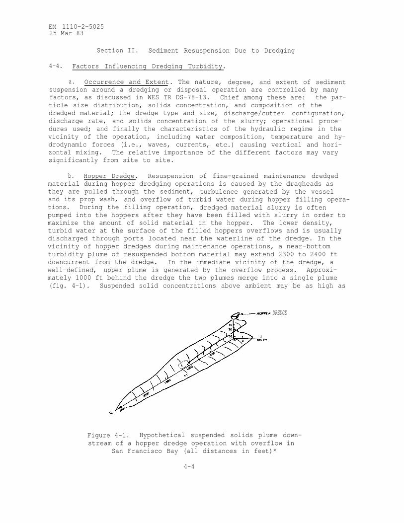
EM 1110-2-502525 Mar 83
Section II. Sediment Resuspension Due to Dredging
4-4. Factors Influencing Dredging Turbidity.
a. Occurrence and Extent. The nature, degree, and extent of sedimentsuspension around a dredging or disposal operation are controlled by manyfactors, as discussed in WES TR DS-78-13. Chief among these are: the par-
ticle size distribution, solids concentration, and composition of the
dredged material; the dredge type and size, discharge/cutter configuration,discharge rate, and solids concentration of the slurry; operational proce-
dures used; and finally the characteristics of the hydraulic regime in the
vicinity of the operation, including water composition, temperature and hy-
drodynamic forces (i.e., waves, currents, etc.) causing vertical and hori-zontal mixing. The relative importance of the different factors may varysignificantly from site to site.
b. Hopper Dredge. Resuspension of fine-grained maintenance dredged
material during hopper dredging operations is caused by the dragheads as
they are pulled through the sediment, turbulence generated by the vesseland its prop wash, and overflow of turbid water during hopper filling opera-
tions. During the filling operation, dredged material slurry is oftenpumped into the hoppers after they have been filled with slurry in order to
maximize the amount of solid material in the hopper. The lower density,
turbid water at the surface of the filled hoppers overflows and is usually
discharged through ports located near the waterline of the dredge. In the
vicinity of hopper dredges during maintenance operations, a near-bottom
turbidity plume of resuspended bottom material may extend 2300 to 2400 ft
downcurrent from the dredge. In the immediate vicinity of the dredge, a
well-defined, upper plume is generated by the overflow process. Approxi-
mately 1000 ft behind the dredge the two plumes merge into a single plume
(fig. 4-1). Suspended solid concentrations above ambient may be as high as
DREDGE
Figure 4-1. Hypothetical suspended solids plume down-
stream of a hopper dredge operation with overflow in
San Francisco Bay (all distances in feet)*
4-4

EM 1110-2-5025
25 Mar 83
several tens of parts per thousand (grams per litre) near the discharge port
and as high as a few parts per thousand near the draghead. Turbiditylevels in the near-surface plume appear to decrease exponentially with in-
creasing distance from the dredge due to settling and dispersion, quickly
reaching concentrations less than 1 ppt. However, plume concentrations mayexceed background levels even at distances in excess of 4000 ft.
c. Bucket or Clamshell Dredge. The turbidity generated by a typicalclamshell operation can be traced to sediment resuspension occurring when
the bucket impacts on and is pulled off the bottom, turbid water spills
out of the bucket or leaks through openings between the jaws, and material
is inadvertently spilled during the barge loading operation. There is a
great deal of variability in the amount of material resuspended by clam-
shell dredges due to variations in bucket size, operating conditions, sedi-ment types, and hydrodynamic conditions at the dredging site. Based onlimited measurements, it appears that, depending on current velocities, the
turbidity plume downstream of a typical clamshell operation may extend ap-
proximately 1000 ft at the surface and 1600 ft near the bottom. Maximum
concentrations of suspended solids in the surface plume should be less
than 0.5 ppt in the immediate vicinity of the operation and decrease
rapidly with distance from the operation due to settling and dilution of
the material. Average water-column concentrations should generally be lessthan 0.1 ppt. The near-bottom plume will probably have a higher solidsconcentration, indicating that resuspension of bottom material near the
clamshell impact point is probably the primary source of turbidity in thelower water column. The visible near-surface plume will probably dissipate
rapidly within an hour or two after the operation ceases.
d. Cutterhead or Hydraulic Pipeline Dredge. Most of the turbidity
generated by a cutterhead dredging operation is usually found in the vi-cinity of the cutter. The levels of turbidity are directly related to the
type and quantity of material cut, but not picked up, by the suction. The
ability of the dredge's suction to pick up bottom material determines the
amount of cut material that remains on the bottom or suspended in the water
column. In addition to the dredging equipment used and its mode of opera-
tion, turbidity may be caused by sloughing of material from the sides of
vertical cuts; inefficient operational techniques; and the prop wash from
the tenders (tugboats) used to move pipeline, anchors, etc., in the shallow
water areas outside the channel. Based on limited field data collected
under low current conditions, elevated levels of suspended material appear
to be localized in the immediate vicinity of the cutter as the dredge
swings back and forth across the dredging site. Within 10 ft of the cutter,
suspended solids concentrations are highly variable but may be as high as
a few tens of parts per thousand; these concentrations decrease exponen-
tially from the cutter to the water surface. Near-bottom suspended solids
concentrations may be elevated to levels of a few tenths of a part per
thousand at distances of less than 1000 ft from the cutter.
4-5

EM 1110-2-502525 Mar 83
Section III. Open-Water Disposal
4-5. Behavior of Discharges from Various Types of Dredges.
a. Hopper Dredge. The characterisitics and operation of hopper
dredges are discussed in para 3-3 of this manual. When the hoppers have
been filled as described, the dragarms are raised and the hopper dredge pro-ceeds to the disposal site. At the disposal site, hopper doors in the bot-
tom of the ship's hull are opened and the entire hopper contents are emptied
in a matter of seconds; the dredge then returns to the dredging site to re-load. This procedure produces a series of discrete discharges at intervals
of perhaps one to several hours. Upon release from the hopper dredge atthe disposal site, the dredged material falls through the water column as a
well-defined jet of high-density fluid which may contain blocks of solidmaterial. Ambient water is entrained during descent. After it hits bottom,
some of the dredged material comes to rest. Some material enters the hori-
zontally spreading bottom surge formed by the impact and is carried away
from the impact point until the turbulence of the surge is sufficiently re-duced to permit its deposition.
b. Bucket or Clamshell Dredge. Bucket dredges remove the sediment
being dredged at nearly its in situ density and place it in barges or scows- -for transportation to the disposal area, as described in para 3-8. Al-
though several barges may be used so that the dredging is essentially con-
tinuous, disposal occurs as a series of discrete discharges. The dredged
material may be a slurry similar to that in a hopper dredge, but often sedi-
ments dredged by clamshell remain in fairly large consolidated clumps and
reach the bottom in this form. Whatever its form, the dredged material de-
scends rapidly through the water column to the bottom, and only a small
amount of the material remains suspended.
c. Cutterhead or Hydraulic Pipeline Dredge. The operation of a cutter-
head dredge, described in para 3-4, produces a slurry of sediment and water
discharged at the disposal site in a continuous stream. As the dredge pro-
gresses up the channel, the pipeline is moved periodically to keep abreast
of the dredge. The discharged dredged material slurry is generally dis-
persed in three modes. Any coarse material, such as gravel, clay balls, or
coarse sand, will immediately settle to the bottom of the disposal area and
usually accumulates directly beneath the discharge point. The vast major-
ity of the fine-grained material in the slurry also descends rapidly to the
bottom in a well-defined jet of high-density fluid, where it forms a low-
gradient circular or elliptical fluid mud mound. Approximately 1 to 3 per-
cent of the discharged material is stripped away from the outside of the
slurry jet as it descends through the water column and remains suspended as
a turbidity plume.
4-6. Dredged Material Dispersion at the Discharge Site.
a. Water-Column Turbidity. The levels of suspended solids in the
water column around a discharge operation generally range from a few hun-
dredths to a few tenths of a part per thousand. Concentrations are highest
near the discharge point and rapidly decrease with increasing distance
4-6

EM 1110-2-502525 Mar 83
downstream from the discharge point and laterally away from the plume cen-
ter line due to settling and horizontal dispersion of the suspended solids.
Concentrations also decrease rapidly between each discrete hopper or barge
discharge and after a pipeline is shut down or moved to a new location.
Under tidal conditions, the plume will be subject to the tidal dynamics of
the particular bay, estuary, or river mouth in which the dredging activity
takes place. Many of the Corps projects have been studied in physical hy-
draulic models, and estimates of plume excursion can be made from their
model reports. Rough estimates can be made from numerical models. Mathe-
matical model result can be materially improved when calibrated by physical
and/or prototype data; except under very simple conditions, all models have
to be verified with prototype or prototype-derived data. In rivers where
the flow is unidirectional, the plume length is controlled by the strength
of the current and the settling properties of the suspended material. In
both estuarine and riverine environments the natural levels of turbulence
and the fluctuations in the rate of slurry discharge will usually cause the
idealized teardrop-shaped plume to be distorted by gyres or eddylike pat-
terns, as in figure 4-2.
b. Fluid Mud. A small percentage of the fine-grained dredged mate-
rial slurry discharged during open-water disposal is dispersed in the water
column as a turbidity plume; however, the vast majority rapidly descends to
the bottom of the disposal area where it accumulates under the discharge
point in the form of a low-gradient fluid mud mound overlying the existing
bottom sediment, as shown in figure 4-3. If the discharge point of a hy-
draulic pipeline dredge is moved as the dredge advances, a series of mounds
will develop. The majority of the mounded material is usually high-density
(nonflowing) fluid mud that is covered by a surface layer of low-density
(flowing or nonflowing) fluid mud. Under quiescent conditions, more than
98 percent of the sediment in the mudflow remains in the fluid mud layer at
concentrations greater than 10 ppt, while the remaining 2 percent may be
resuspended by mixing with the overlying water at the fluid mud surface.
Fluid mud will tend to flow downhill as long as the bottom slope is ap-
proximately 1 percent or greater. A study of hopper dredge disposal at
Carquinez Strait, San Francisco Bay, showed concentrations of dredged mate-
rial in the water column were generally less than 0.2 ppt above background
and persisted for only a few tens of minutes. However, 3 to 8 ft above the
bottom, concentrations reached 20 ppt in a fluid mud layer. Similar occur-
rences of low suspended sediment concentrations in the water column with
concentrations on the order of several tens of parts per thousand just
above the bottom, as in figure 4-4, have been discussed for pipeline dredge
discharges in WES TR DS-78-13. These conditions persist for the duration
of the disposal operation at the site and for varying times thereafter as
the material consolidates to typical sediment density.
c. Mounding. If bottom slopes are not great enough to maintain mud-
flows, the fluid mud will stop and begin to consolidate. When suspended
sediment concentrations exceed 200 ppt the fluid mud can no longer flow
freely but will accumulate around the discharge point in a low-gradient
(e.g., 1:500) fluid mud mound. At the water column/fluid mud interface,
the solids concentration increases very abruptly from perhaps a few tenths
of a part per thousand in the water to approximately 200 ppt in the fluid
4-7
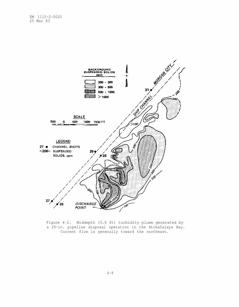
EM 1110-2-502525 Mar 83
Figure 4-2.
a 28-in.
Middepth (3.0 ft) turbidity plume generated by
pipeline disposal operation in the Atchafalaya Bay.
Current flow is generally toward the northeast.
4-8

EM 1110-2-502525 Mar 83
NO CURRENT C.
VERTICAL DISCHARGE
Figure 4-3. Effect of discharge
PREDOMINANTCURRENT
D
HORIZONTAL DISCHARGE
angle and predominant current direction
on the shape of a fluid mud mound.
4-9

EM 1110-2-5025
25 Mar 83
Figure 4-4. Relationship between suspended solids concentration
along the plume center line and distance downcurrent from several
open-water pipeline disposal operations measured at the indicated
water depths,
4-10
EM 1110-2-5025
25 Mar 83
mud. The solids concentration within the fluid mud increases above 200 ppt
at a slower rate with depth until it reaches normal sediment densities.
Deeper layers of fluid mud reach their final degree of consolidation more
rapidly than thinner ones. Depending on the thickness of the fluid mud and
its sedimentation/consolidation characteristics, complete consolidation of
a fluid mud mound may require from one to several years. In those situa-
tions where material dredged by bucket or clamshell is of slurry consis-
tency, the above description is generally applicable. More commonly, how-ever, muddy sediments dredged by a clamshell remain in large clumps and
descend to the bottom in this form. These may break apart somewhat on im-
pact; but such material tends to accumulate in irregular mounds under the
discharge vessel, rather than move outward from the discharge point. What-
ever the dredging method, sandy sediments tend to mound directly beneaththe discharge pipe or vessel.
d. Special Circumstances. Knowledge of the behavior of discharged
dredged material allows control of the dispersion of the material at thedisposal site. When minimum dispersal is desired, the dredged material can
be discharged into old underwater borrow pits, sand or gravel excavation
sites, etc. Such deposits may be further isolated from the overlying water
column by covering with a layer of uncontaminated sediment. It is also
possible to place such a covering, or "cap," over dredged material dis-
charged onto a flat bottom.
4-7. Environmental Impacts in the Water Column.
a. Contaminants. Although the vast majority of heavy metals, nutri-
ents, and petroleum and chlorinated hydrocarbons are usually associated
with the fine-grained and organic components of the sediment (see WES
TR DS-78-4), there is no biologically significant release of these chemical
consituents from typical dredged material to the water column during or
after dredging or disposal operations. Levels of manganese, iron, ammonium
nitrogen, orthophosphate, and reactive silica in the water column may be
increased somewhat for a matter of minutes over background conditions dur-
ing open-water disposal operations; however, there are no persistent well-
defined plumes of dissolved metals or nutrients at levels significantly
greater than background concentrations.
b. Turbidity. There are now ample research results indicating that
the traditional fears of water-quality degradation resulting from the re-
suspension of dredged material during dredging and disposal operations are
for the most part unfounded. The possible impact of depressed levels of
dissolved oxygen has also been of some concern, due to the very high oxygen
demand associated with fine-grained dredged material slurry. However, even
at open-water pipeline disposal operations where the dissolved oxygen de-
crease should theoretically be greatest, near-surface dissolved oxygen
levels of 8 to 9 ppm will be depressed during the operation by only 2 to
3 ppm at distances of 75 to 150 ft from the discharge point. The degree of
oxygen depletion generally increases with depth and increasing concentra-
tion of total suspended solids; near-bottom levels may be less than 2 ppm.
However, dissolved oxygen levels usually increase with increasing distance
4-11

EM 1110-2-502525 Mar 83
from the discharge point, due to dilution and settling of the suspendedmaterial.
(1) It has been demonstrated that elevated suspended solids concentra-
tions are generally confined to the immediate vicinity of the dredge or dis-
charge point and dissipate rapidly at the completion of the operation. If
turbidity is used as a basis for evaluating the environmental impact of a
dredging or disposal operation, it is essential that the predicted turbidity
levels are evaluated in light of background conditions. Average turbidity
levels, as well as the occasional relatively high levels that are often as-
sociated with naturally occurring storms, high wave conditions, and floods,
should be considered.
(2) Other activities of man may also be responsible for generating as
much or more turbidity than dredging and disposal operations. For example,each year shrimp trawlers in Corpus Christi Bay, Texas, suspend 16 to 131
times the amount of sediment that is dredged annually from the main ship
channel. In addition, suspended solids levels of 0.1 to 0.5 ppt generatedbehind the trawlers are comparable to those levels measured in the tur-
bidity plumes around open-water pipeline disposal operations. Resuspensionof bottom sediment in the wake of large ships, tugboats, and tows can also
be considerable. In fact, where bottom clearance is 3 ft or less, there
may be scour to a depth of 3 ft if the sediment is easily resuspended.
4-8. Environmental Impacts on the Benthos.
a. Physical. Whereas the impact associated with water-column tur-
bidity around dredging and disposal operations is for the most part insig-nificant, the dispersal of fluid mud dredged material appears to have a
relatively significant short-term impact on the benthic organisms within
open-water disposal areas. Open-water pipeline disposal of fine-grained
dredged material slurry may result in a substantial reduction in the aver-
age abundance of organisms and a decrease in the community diversity in the
area covered by fluid mud. Despite this immediate impact, recovery of the
community apparently begins soon after the disposal operation ceases.
(1) Disposal operations will blanket established bottom communities
at the site with dredged material which may or may not resemble bottom sedi-
ments at the disposal site. Recolonization of animals on the new substrate
and the vertical migration of benthic organisms in newly deposited sediments
can be important recovery mechanisms. The first organisms to recolonize
dredged material usually are not the same as those which had originally oc-
cupied the site; they consist of opportunistic species whose environmental
requirements are flexible enough to allow them to occupy the disturbed
areas. Trends toward reestablishment of the original community are often
noted within several months of disturbance, and complete recovery approached
within a year or two. The general recolonization pattern is often dependent
upon the nature of the adjacent undisturbed community, which provides a
pool of replacement organisms capable of recolonizing the site by adult mi-
gration or larval recruitment.
4-12

EM 1110-2-502525 Mar 83
(2) Organisms have various capabilities for moving upward through
newly deposited sediments, such as dredged material, to reoccupy positions
relative to the sediment-water interface similar to those maintained prior
to burial by the disposal activity. Vertical migration ability is greatestin dredged material similar to that in which the animals normally occur and
is minimal in sediments of dissimilar particle-size distribution. Bottom-dwelling organisms having morphological and physiological adaptations for
crawling through sediments are able to migrate vertically through several
inches of overlying sediment. However, physiological status and environ-mental variables are of great importance to vertical migration ability.
Organisms of similar life-style and morphology react similarly when coveredwith an overburden. For example, most surface-dwelling forms are generallykilled if trapped under dredged material overburdens, while subsurface
dwellers migrate to varying degrees. Laboratory studies suggest verticalmigration may very well occur at disposal sites, although field evidence is
not available. Literature review (WES TR DS-78-1) indicates the vertical
migration phenomenon is highly variable among species.
(3) Dredging and disposal operations have immediate localized effects
on the bottom life. The recovery of the affected sites occurs over periodsof weeks, months, or years, depending on the type of environment and the
biology of the animals and plants affected. The more naturally variablethe physical environment, especially in relation to shifting substrate dueto waves or currents, the less effect dredging and disposal will have.
Animals and plants common to such areas of unstable sediments are adapted
to physically stressful conditions and have life cycles which allow them to
withstand the stresses imposed by dredging and disposal. Exotic sediments
(those in or on which the species in question does not normally live) are
likely to have more severe effects when organisms are buried than sediments
similar to those of the disposal site. Generally, physical impacts are
minimized when sand is placed on a sandy bottom and are maximized when mud
is deposited over a sand bottom. When disposed sediments are dissimilar to
bottom sediments at the sites, recolonization of the dredged material will
probably be slow and carried out by organisms whose life habits are adapted
to the new sediment. The new community may be different from that origi-
nally occurring at the site.
(4) Dredged material discharged at disposal sites which have a natu-
rally unstable or shifting substrate due to wave or current action is
rather quickly dispersed and does not cover the area to substantial depths.
This natural dispersion, which usually occurs most rapidly and effectively
during the stormy winter season, can be assisted by conducting the disposal
operation so as to maximize the spread of dredged material, producing the
thinnest possible overburden. The thinner the layer of overburden, the
easier it is for mobile organisms to survive burial by vertical migration
through dredged material. The desirability of minimizing physical impacts
by dispersion can be overridden by other considerations, however. For ex-
ample, dredged material shown by biological or chemical testing to have a
potential for adverse environmental impacts might best be placed in an area
of retention, rather than dispersion. This would maximize habitat disrup-
tion in a restricted area, but would confine potentially more important
chemical impacts to tha same small area.
4-13

EM 1110-2-5025
25 Mar 83
(5) Since larval recruitment and migration of adults are primary
mechanisms of recolonization, recovery from physical impacts will generally
be most rapid if disposal operations are completed shortly before the sea-
sonal increase in biological activity and larval abundance in the area.
The possibility of impacts can also be reduced by locating disposal sites
in the least sensitive or critical habitats. This can sometimes be done ona seasonal basis. Known fish migratory routes and spawning beds should beavoided just before and during use, but might be acceptable for disposalduring other periods of the year. However, care must be taken to ensurethat the area returns to an acceptable condition before the next intensive
use by the fish. Clam or oyster beds, municipal or industrial water in-takes, highly productive backwater areas, etc., should be avoided in select-
ing disposal sites.
(6) All the above factors should be evaluated in selecting a disposalsite, method, and season in order to minimize the habitat disruption of dis-posal operations. All require evaluations on a case-by-case basis by per-
sons familiar with the ecological principles involved, as well as the char-
acteristics of the proposed disposal operations and the local environment.
b. Contaminants.
(1) Dredging and disposal do not introduce new contaminants to the
aquatic environment, but simply redistribute the sediments which are the
natural depository of contaminants introduced from other sources. The po-
tential for accumulation of a metal in the tissues of an organism (bioaccu-
mulation) may be affected by several factors such as duration of exposure,
salinity, water hardness, exposure concentration, temperature, the chemicalform of the metal, and the particular organism under study. The relative
importance of these factors varies from metal to metal, but there is a
trend toward greater uptake at lower salinities. Elevated concentrations
of heavy metals in tissues of benthic invertebrates are not always indica-
tive of high levels of metals in the ambient medium or associated sediments.
Although a few instances of uptake of possible ecological significance have
been shown, the diversity of results among species, different metals, types
of exposure, and salinity regimes strongly argues that bulk analysis of
sediments for metal content cannot be used as a reliable index of metal
availability and potential ecological impact of dredged material, but only
as an indicator of total metal context. Bioaccumulation of most metals
from sediments is generally minor. Levels often vary from one sample pe-
riod to another and are quantitatively marginal, usually being less than
one order of magnitude greater than levels in the control organisms, even
after one month of exposure. Animals in undisturbed environments may
naturally have high and fluctuating metal levels. Therefore, in order to
evaluate bioaccumulation, comparisons should be made between control and
experimental organisms at the same point in time.
(2) Organochlorine compounds such as DDT, dieldrin, and polychlori-
nated biphenyls (PCB's) are environmental contaminants of worldwide sig-
nificance which are manmade and, therefore, do not exist naturally in the
earth's crust. Organochlorine compounds are generally not soluble in sur-
face waters at concentrations higher than approximately 20 ppb, and most of
4-14
EM 1110-2-502525 Mar 83
the amount present in waterways is associated with either biological organ-
isms or suspended solids. Organochlorine compounds are released from sedi-
ment until some equilibrium concentration is achieved between the aqueous
and the solid phases and then readsorbed by other suspended solids or bio-
logical organisms in the water column. The concentration of organochlorinesin the water column is reduced to background levels within a matter of hours
as the organochlorine compounds not taken up by aquatic organisms eventually
settle with the particulate matter and become incorporated into the bottom
deposits in aquatic ecosystems. Most of these compounds are stable and mayaccumulate to relatively high concentrations in the sediments. The manu-facture and/or disposal of most of these compounds is now severely limited;
however, sediments that have already been contaminated with organochlorine
compounds will probably continue to have elevated levels of these compounds
for several decades. The low concentrations of chlorinated hydrocarbons in
sediment interstitial water indicate that during dredging operations, the
release of the interstitial water and contaminants to the surrounding en-
vironment would not create environmental problems. Bioaccumulation ofchlorinated hydrocarbons from deposited sediments does occur. However, thesediments greatly reduce the bioavailability of these contaminants, and tis-
sue concentrations may range from less than one to several times the sedi-
ment concentration. Unreasonable degradation of the aquatic environment
due to the routine maintenance dredging and disposal of sediment contami-
nated with chlorinated hydrocarbons has never been demonstrated.
(3) The term “oil and grease” is used collectively to describe allcomponents of sediments of natural and contaminant origin which are pri-
marily fat soluble. There is a broad variety of possible oil and grease
components in sediment, the analytical quantification of which is dependent
on the type of solvent and method used to extract these residues. Trace
contaminants, such as PCB’s and chlorinated hydrocarbons, often occur in
the oil and grease’. Large amounts of contaminant oil and grease find their
way into the sediments of the Nation’s waterways either by spillage or as
chronic inputs in municipal and industrial effluents, particularly near
urban areas with major waste outfalls. The literature suggests long-term
retention of oil and grease residues in sediments, with minor biodegrada-
tion occurring. Where oily residues of known toxicity became associated
with sediments, these sediments retained toxic properties over periods of
years, affecting local biota. Spilled oils are known to readily become ad-
sorbed to naturally occurring suspended particulates, and oil residues in
municipal and industrial effluents are commonly found adsorbed to particles.
These particulates are deposited in sediments and are subject to suspension
during disposal. Even so, there is only slight desorption, and the amount
of oil released during the elutriate test is less than 0.01 percent of the
sediment-associated hydrocarbons under worst-case conditions. Selected
estuarine and freshwater organisms exposed for periods up to 30 days to
dredged material that is contaminated with thousands of parts per million
of oil and grease experience minor mortality. Uptake of hydrocarbons from
heavily contaminated sediments appears minor when compared with the hydro-
carbon content of the test sediments.
(4) Ammonia is one of the potentially toxic materials known to be re-
leased from sediments during disposal; it is routinely found in evaluations
4-15

EM 1110-2-5025
25 Mar 83
of sediments using the elutriate test and in the water near a disposal area
where concentrations rapidly return to baseline levels. Similar temporary
increases in ammonia at marine, estuarine, and freshwater disposal sites
have been documented in several DMRP field studies, but concentrations and
durations are usually well below levels causing concern.
(5) The potential environmental impact of contaminants associatedwith sediments must be evaluated in light of chemical and biological data
describing the availability of contaminants to organisms. Information must
then be gained as to the effects of specific substances on organism survivaland function. Many contaminants are not readily released from sediment at-tachment and are thus less toxic than contaminants in the free or soluble
state on which most toxicity data are based.
(6) There are now cogent reasons for rejecting many of the conceptual-
ized impacts of disposed dredged material based on classical bulk analysisdeterminations. It is invalid to use total sediment concentration to esti-mate contaminant levels in organisms since only a variable and undetermined
amount of sediment-associated contaminant is biologically available. Al-
though a few instances of toxicity and bioaccumulation of possible ecologi-
cal consequence have been seen, the fact that the degree of effect dependson species, contaminants, salinity, sediment type, etc., argues strongly
that bulk analysis does not provide a reliable index of contaminant avail-
ability and potential ecological impact of dredged material.
4-9. Overview of Open-Water Disposal.
a. Prediction of physical effects of dredging and disposal is fairly
straightforward. Physical effects include removal of organisms at dredging
sites and burial of organisms at disposal sites. Physical effects are re-
stricted to the immediate areas of dredging or disposal. Recolonization of
sites occurs in periods of months to 1-2 years in case studies. Disturbed
sites may be recolonized by opportunistic species which are not normally
the dominant species occurring at the site.
b. Many organisms are very resistant to the effects of sediment sus-pensions in the water; aside from natural systems requiring clear water,
such as coral reefs and some aquatic plant beds, dredging or disposal-
induced turbidity is not of major ecological concern. The formation of
fluid muds due to disposal is not fully understood and is of probable en-
vironmental concern in some situations.
c. Release of sediment-associated heavy metals and chlorinated hydro-
carbons to the water column by dredging and disposal has been found to be
the exception, rather than the rule. Metals are rarely bioaccumulated from
sediments and then only to low levels. Chlorinated hydrocarbons may be bio-
accumulated from sediments, but only very highly contaminated sediments
might result in tissue concentrations of potential concern. There is little
or no correlation between bulk analysis of sediments for contaminants and
their environmental impact.
4-16

EM 1110-2-5025
25 Mar 83
d. Oil and grease residues, like heavy metals, are tightly bound to
sediment particles, and there appears to be minimal uptake of the residues
into organism tissues. Of the thousands of chemicals constituting the oil
and grease fraction, very few can be considered significant threats to
aquatic life when associated with dredged material.
e. Many laboratory studies describe worst-case experimental condi-
tions where relatively short-term exposures to high concentrations of sedi-
ments and contaminants are investigated. Although limited in scope, experi-
mental results showing the lack of effects under these worst-case conditions
support the conclusion that the indirect long-term and sublethal effects of
dredging and disposal will be minimal. An integrated, whole-sediment bio-assay using sensitive test organisms should be used to determine potential
sediment impacts at a particular site. Appropriate chemical testing andbiological evaluation of the dredged material can be used to resolve any
site-specific problems which may occur.
Section IV. Confined Dredged Material Disposal
4-10. Containment Area Design.
a. Concepts of Containment Area Operation.
(1) Diked containment areas are used to retain dredged material
solids while allowing the carrier water to be released from the containment
area. The two objectives of a containment area are: (a) to provide ade-
quate storage capacity to meet dredging requirements and (b) to attain the
highest possible efficiency in retaining solids during the dredging opera-
tion in order to meet effluent suspended solids requirements. These con-
siderations are interrelated and depend upon effective design, operation,
and management of the containment area. Major considerations in design of
containment areas are discussed below. Detailed design guidance may be
found in WES TR DS-78-10.
(2) The major components of a dredged material containment area areshown schematically in figure 4-5. A tract of land is surrounded by dikes
to form a confined surface area into which dredged channel sediments are
pumped hydraulically. In some dredging operations, especially in the case
of new work dredging, sand, clay balls, and/or gravel may be present. Thi
coarse material rapidly falls out of suspension and forms a mound near the
dredge inlet pipe. The fine-grained material (silt and clay) continues to
flow through the containment area where most of the solids settle out of
suspension and thereby occupy a given storage volume. The fine-grained
dredged material is usually rather homogeneous and is easily characterized
The clarified water is discharged from the containment area over a weir.This effluent can be characterized by its suspended solids concentration
and rate of outflow. Effluent flow rate is approximately equal to influent
flow rate for continuously operating disposal areas. To promote effective
sedimentation, ponded water is maintained in the area; the depth of water
is controlled by the elevation of the weir crest. The thickness of the
dredged material layer increases with time until the dredging operation is
completed. Minimum freeboard requirements and mounding of coarse-grained
4-17

EM 1110-2-502525 Mar 83
Figure 4-5. Schematic diagram of a dredged material containment area,
material result in a ponded surface area smaller than the total surface area
enclosed by the dikes. In most cases, confined disposal areas must be uti-lized over a period of many years, storing material dredged periodicallyover the design life. Long-term storage capacity for these sites is influ-
enced by consolidation of dredged material and foundation soils, dewatering
of material, and effective management of the disposal area.
b. Evaluation of Dredging Activities. Effective planning and design
of containment areas first requires a thorough evaluation of the dredging
program. The location, volumes, frequencies, and types of material to be
dredged must be estimated. The number, types, and sizes of dredges normallyemployed to do the work should also be considered. This information is im-
portant for defining project objectives and provides a basis for containment
area design.
4-18

EM 1110-2-502525 Mar 83
c. Field Investigations.
(1) Samples of the channel sediments to be dredged are required for
adequate characterization of the material and for use in sedimentation and
consolidation testing. The level of effort required for channel sedimentsampling depends upon the project. In the case of routine maintenance work,data from prior samplings and experience with similar material may be avail-able to reduce the scope of field investigations. Since maintenance sedi-ments are in an essentially unconsolidated state, grab samples are normally
satisfactory for sediment characterization purposes and are easy and inex-
pensive to obtain. For unusual maintenance projects or new work, more ex-tensive field investigations will be required.
(2) Field investigations must also be performed at the containment
area site to define foundation conditions and to obtain samples for labora-
tory testing if estimates of long-term storage capacity are required. Theextent of required field investigations is dependent upon project size and
upon foundation conditions at the site. It is particularly important todefine foundation conditions, including depth, thickness, extent, and compo-sition of foundation strata, and to obtain undisturbed samples of compres-sible foundation soils and any previously placed dredged material. If pos-sible, the field investigations required for estimating long-term storage
capacity should be planned and accomplished along with those required for
the engineering design of the retaining dikes.
d. Laboratory Testing.
(1) Laboratory tests are required primarily to provide data for sedi-ment characterization, containment area design, retention dike design, andlong-term storage capacity estimates. The laboratory tests and procedures
required are essentially standard tests and generally follow accepted pro-
cedures. The required magnitude of the laboratory testing program depends
upon the project. Fewer tests are usually required when dealing with a
relatively homogeneous material and/or when data are available from pre-
vious tests and experience, as is frequently the case in maintenance work.
For unusual maintenance projects where considerable variation in sediment
properties is apparent from samples, or for new work projects, more ex-
tensive laboratory testing programs are required. Refer to WES TR DS-78-10
for details on testing procedures.
(2) Sedimentation tests, performed in 8-in.-diameter ported columns
as shown in figure 4-6, are necessary to provide design data for retention
of suspended solids (item 4). These tests are designed to define the floc-
culent or zone-settling behavior of a particular sediment and to provide
information concerning the volumes occupied by newly placed layers ofdredged material. Sedimentation of freshwater sediments at slurry concen-
trations of less than 100 ppt can generally be characterized by flocculent
settling properties. As slurry concentrations are increased, the sedimenta-
tion process may be characterized by zone-settling properties. Salinity
greater than 3 ppt enhances the flocculation of dredged material particles;
therefore, the settling properties of saltwater dredged material can usually
be characterized by zone-settling tests. The flocculent settling test
4-19

EM 1110-2-5025
25 Mar 83
Figure 4-6. Schematic of apparatus for settling tests.
consists of measuring the concentration of suspended solids at various
depths and time intervals by withdrawing samples from the settling columnports. The zone-settling test consists of placing a slurry in a settling
column and timing the fall of the liquid-solids interface.
(3) Determination of containment area long-term storage capacity re-
quires estimates of settlement due to self-weight consolidation of newly
placed dredged material and due to consolidation of compressible foundation
soils. Consolidation test results, including time-consolidation data, must
therefore be obtained. Consolidation tests for foundation soils should be
4-20

EM 1110-2-5025
25 Mar 83
performed as described in EM 1110-2-1906 with no modifications. The con-
solidation testing procedure for sediment samples generally follows that
for the fixed ring test for conventional soils, but minor modifications in
sample preparation and loading are required (WES TR DS-78-10).
e. Design for Retention of Suspended Solids.
(1) Sedimentation, as applied to dredged material disposal activities,
refers to those operations in which the dredged material slurry is sepa-
rated into more clarified water and a more concentrated slurry. Laboratory
sedimentation tests must provide data for designing the containment area to
meet effluent suspended solids criteria and to provide adequate storage
capacity for the dredged solids. These tests are based on the gravity
separation of solid particles from the transporting water.
(2) The sedimentation process can be categorized according to three
basic classifications:
(a) Discrete settling. The particle maintains its individuality and
does not change in size, shape, or density during the settling process.
(b) Flocculent settling. Particles agglomerate during the settling
period with a change in physical properties and settling rate.
(c) Zone settling. The flocculent suspension forms a lattice struc-
ture and settles as a mass, exhibiting a distinct interface during the set-
tling process.
(3) The important factors governing the sedimentation of dredged mate-
rial solids are the initial concentration of the slurry and the flocculat-
ing properties of the solid particles. Montgomery (item 4) demonstrated by
experiments that, because of the high influent solids concentration and the
tendency of dredged material fine-grained particles to flocculate, either
flocculate or zone-settling behavior governs sedimentation in containment
areas. Discrete settling describes the sedimentation of sand particles and
fine-grained sediments at concentrations much lower than those found in
dredged material containment areas. Test results using the 8-in.-diameter
settling column are used to design the containment area for solids reten-
tion based on principles of flocculent or zone settling. Detailed design
procedures found in WES TR DS-78-10 will determine surface area, contain-
ment area volume, ponding depth, and freeboard requirements. The designs
must consider the hydraulic efficiency of the containment, based on shape
and topography, and the proper sizing of outlet structures.
f. Evaluation of Long-Term Storage Capacity.
(1) If the containment area is intended for one-time use, as is the
case in some new work projects, estimates of long-term storage capacity are
not required. However, containment areas intended for use in recurring
maintenance work must be sized for long-term storage capacity over the ser-
vice life of the facility. Storage capacity is defined as the total volume
available to hold additional dredged material and is equal to the total
4-21

EM 1110-2-502525 Mar 83
unoccupied volume minus the volume associated with ponding and freeboard
requirements.
(2) The following factors must be considered in estimating long-term
containment area storage capacity:
(a) After dredged material is placed within a containment area, it
undergoes sedimentation and self-weight consolidation resulting in gains in
storage capacity.
(b) The placement of dredged material imposes a loading on the contain-
ment area foundation, and additional settlement may result due to consolida-
tion of compressible foundation soils.
(c) Since the consolidation process is slow, especially in the caseof fine-grained materials, it is likely that total settlement will not have
taken place before space in the containment area is required for additional
placement of dredged material. For this reason, the time-consolidation re-
lationship is an important consideration.
(d) Settlement of the containing dikes significantly affects the
available storage capacity.
(3) Estimation of gains in long-term capacity can be made using re-
sults of laboratory consolidation tests and application of fundamental prin-
ciples of consolidation modified to consider the self-weight consolidation
behavior of newly placed dredged material. Detailed procedures for esti-
mating long-term storage capacity are found in WES TR DS-78-10.
g. Weir Design. The purpose of the weir structure is to regulate re-
lease of ponded water from the containment area. Proper weir design and
operation can control resuspension and withdrawal of settled solids. This
is possible only if the containment areas have been properly designed to
provide sufficient area and volume for sedimentation. Weirs are designed
to provide selective withdrawal of the clarified upper layer of ponded
water. In order to maintain acceptable effluent quality, the upper water
layers containing low levels of suspended solids should be ponded at depths
greater than the depth of the withdrawal zone; i.e., the area through which
fluid is removed for discharge over the weir. The size of the withdrawal
zone as determined by the weir loaction and configuration affects the
velocity of flow toward the weir. Detailed considerations in weir design
and design nomographs for determining required weir crest lengths are
found in WES TR DS-78-10. Weirs should be structurally designed to with-
stand anticipated loadings at maximum ponding elevations, with considera-
tion given to uplift forces and potential piping beneath or around the wier.
Outlet pipes for the weir structure must be designed to carry flows in ex-
cess of the flow rate for the largest dredge size expected to provide for
emergency release of ponded waters.
h. Chemical Clarification for Reduction of Effluent Suspended Solids.
4-22

EM 1110-2-502525 Mar 83
(1) When dredged material slurry is disposed in a well-designed, well-
managed containment area, the vast majority of the solids will settle out
of suspension and be retained within the settling basin. However, gravitysedimentation alone will not remove all suspended solids. Any fine-grainedmaterial suspended in the ponded water above the settled solids will be
discharged in the effluent water. In addition, the levels of chemical con-stituents in the effluent water are directly related to the amount of sus-
pended fine-grained material; therefore, retention of fine-grained solidsin the containment area results in a maximum degree of retention of poten-
tially toxic chemical constituents. Effluent standards may require removalof suspended solids over and above that attained by gravity sedimentation.
(2) In the absence of a fully engineered treatment system, severalexpedient measures can be employed to enhance retention of the suspended
solids within a containment area of a given size before effluent discharge.
They include: intermittent pumping, increasing the depth of ponded water,increasing the effective length of the weir, temporarily discontinuing op-erations, or decreasing the size of the dredge.
(3) Flocculation. One method specifically for reducing the levels of
fine-grained (clay-sized) suspended solids levels in the effluent involves
treating the containment area effluent or the dredged material slurry with
chemical flocculants to encourage the formation of flocs (i.e., particle
agglomerates) that settle more rapidly than individual particles. This ag-
glomeration or coagulation process is accomplished by an alteration of the
electrochemical properties of the clay particles and the bridging of par-
ticles and small flocs by long polymer chains. Because of the large number
of manufacturers of polyelectrolytes and the types available, preliminary
screening of flocculants is necessary. Evaluation and determination of the
optimum dose of several nontoxic polymers may be accomplished using jar-
testing procedures. These procedures will indicate the most cost-effective
polymer and the optimum dosage of the polymer solution for treating the sus-
pended solids levels, as well as the optimum mixing intensities and dura-
tions for both rapid- and slow-mixing stages. Optimum detention times and
surface overflow rates for clarifying the flocced suspensions and a general
indication of the volume of flocced material that must be stored or re-
handled can be determined from settling tests. Schroeder (item 8) presents
design guidance for the use of chemical clarification methods.
i. Dike Design. Dikes for retaining or confining dredged material
are normally earthen embankments similar to flood protection levees. Dike
locations are usually determined by land available-for disposal areas;therefore, dikes sometimes must be constructed in areas of poor foundation
quality and from materials of poor construction quality. In past years, re-
taining dikes for dredged material have been designed and constructed with
less effort and expense than other engineered structures. The potential for
dike failures and the environmental and economic damage which can result
dictate that retaining dikes be properly designed and constructed using the
principles of geotechnical engineering. Foundation investigations and labo-
ratory soils tests and analyses must be conducted to design dikes to the de-
sired degree of safety against failures. Procedures used in dike design
4-23

EM 1110-2-502525 Mar 83
generally parallel those required for design of flood protection levees or
earth-filled dams. WBS TR D-77-9 contains detailed guidelines for the de-
sign and construction of retaining dikes.
4-11. Containment Area Operation and Management.
a. Containment Area Operation. A major consideration in proper con-tainment area operation is providing the ponding necessary for sedimenta-
tion and retention of suspended solids. Adequate ponding depth during thedredging operation is maintained by controlling the weir crest elevation,
usually by placing boards within the weir structure. Before dredging com-mences, the weir should be boarded to the highest possible elevation that
dike stability considerations will allow. This practice will ensure maxi-mum possible efficiency of the containment area. The maximum elevationmust allow for adequate ponding depth above the highest expected level of
accumulated settled solids and yet remain below the required freeboard. If
the basin is undersized or if inefficient settling is occurring in the
basin, it is necessary to increase detention time and reduce approach veloc-
ity to achieve efficient settling and to avoid resuspension, respectively.
Detention time can be increased by raising the weir crest to its highest
elevation to increase the ponding depth; or it may be increased by operat-
ing the dredge intermittently to maintain a maximum allowable static head
or depth of flow over the weir, based on the effluent quality achieved atvarious weir crest elevations. Once the dredging operation is completed,the ponded water must be removed to promote drying and consolidation of
dredged material. Refer to WES TR DS-78-10.
b. Containment Area Management.
(1) Periodic site inspections. The importance of periodic site in-
spections and continuous site management following the dredging operation
cannot be overemphasized. Once the dredging operation has been completed
and the ponded water has been decanted, site management efforts should be
concentrated on maximizing the containment storage capacity gained from
continued drying and consolidation of dredged material and foundation soils.
To ensure that precipitation does not pond water, the weir crest elevation
must be kept at levels allowing efficient release of runoff water. This
will require periodic lowering of the weir crest elevation as the dredged
material surface settles.
(2) Thin-lift placement. Gains in long-term storage capacity of con-
tainment areas through natural drying processes can also be increased by
placing the dredged material in thin lifts. Thin-lift placement greatly
increases potential capacity through active dewatering and disposal area
reuse management programs. Thin-lift placement can be achieved by obtain-
ing sufficient land area to ensure adequate storage capacity without the
need for thick lifts. It requires careful long-range planning to ensure
that the large land area is used effectively for dredged material dewater-
ing, rather than simply being a containment area whose service life is
longer than that of a smaller area. Dividing a large containment area into
several compartments can facilitate management; each compartment can be
managed separately so that some compartments are being filled while the
4-24
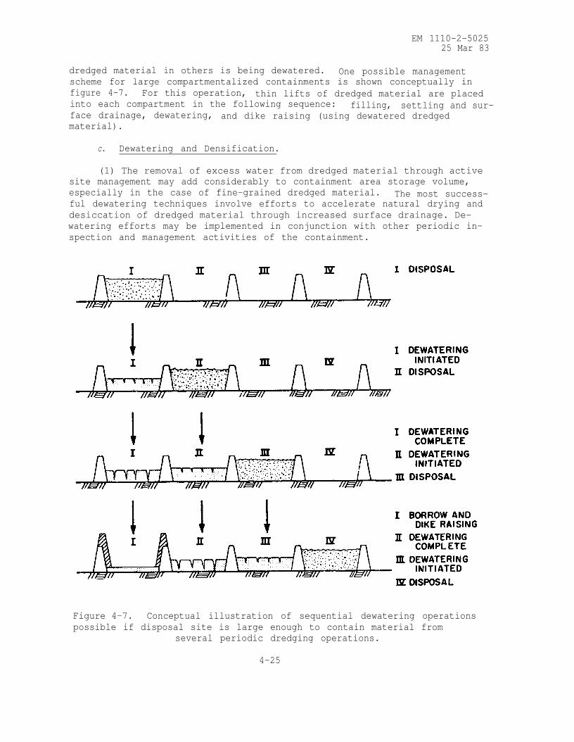
EM 1110-2-502525 Mar 83
dredged material in others is being dewatered. One possible managementscheme for large compartmentalized containments is shown conceptually in
figure 4-7. For this operation, thin lifts of dredged material are placedinto each compartment in the following sequence: filling, settling and sur-face drainage, dewatering, and dike raising (using dewatered dredgedmaterial).
c. Dewatering and Densification.
(1) The removal of excess water from dredged material through activesite management may add considerably to containment area storage volume,
especially in the case of fine-grained dredged material. The most success-ful dewatering techniques involve efforts to accelerate natural drying and
desiccation of dredged material through increased surface drainage. De-
watering efforts may be implemented in conjunction with other periodic in-
spection and management activities of the containment.
Figure 4-7. Conceptual illustration of sequential dewatering operations
possible if disposal site is large enough to contain material from
several periodic dredging operations.
4-25

EM 1110-2-502525 Mar 83
(2) Dredged material is usually placed in confined disposal areas in
a slurry state. Although a significant amount of water runs off through
the overflow weirs of the disposal area, the confined fine-grained dredged
material usually sediments/consolidates to only a semifluid consistency
that still contains large amounts of water. Not only does the high water
content greatly reduce available future disposal volume, but it also makes
the dredged material unsuitable or undesirable for any commercial or pro-
ductive use.
(3) Three major reasons exist for dewatering fine-grained dredged ma-
terial placed in confined disposal areas:
(a) Promotion of shrinkage and consolidation to increase volume in
the existing disposal site for additional dredged material.
(b) Reclamation of the dredged material into more stable soil form
for removal and use in dike raising or other engineered construction, or
for other productive uses, again increasing volume in the existing disposal
site.
(c) Creation of stable, fast land at the disposal site itself, at a
known final elevation and with predictable geotechnical properties.
(4) Allowing evaporative forces to dry fine-grained material into a
crust while gradually lowering the internal water table is the least ex-
pensive and most widely applicable dewatering method. Good surface drain-
age, rapidly removing precipitation and preventing ponding of surface
water, accelerates evaporative drying. Shrinkage forces developed during
drying return the material to more stable form; lowering the internal water
table results in further consolidation.
(5) Trenching. The most efficient method for promoting good surface
drainage is to construct drainage trenches in the disposal area. Because
several types of equipment have been found effective for progressive trench-
ing to improve disposal area surface drainage, no unique set of trenching
equipment and procedures exists. The proper equipment for any dewatering
program will depend upon the following factors: size of the disposal area,
whether or not desiccation crust currently exists (and, if so, of what
thickness), time available for dewatering operations, type of site access,
condition of existing perimeter dikes, time available between disposal
cycles, and availability of and rental and operating cost for various types
of trenching equipment.
(6) Underdrainage. Underdrainage is another dewatering method which
may be used either individually or in conjunction with improved surfacedrainage. In this procedure, collector pipes are placed in either a natu-
rally occurring or artificially placed pervious layer before dredged mate-
rial disposal. Upon disposal, free water in the dredged material migrates
into the pervious underdrainage layer and is removed via the collector pipe
system. Although technically feasible, underdrainage may not be cost-
effective in many disposal situations. Detailed discussions of dredged
material dewatering are found in WES TR DS-78-11.
4-26
EM 1110-2-502525 Mar 83
d. Disposal Area Reuse. Removal of coarse-grained material and de-
watered fine-grained material from containment areas through proper manage-
ment techniques will further add to capacity and may be implemented in con-
junction with dike maintenance or raising. Removal of fine-grained dredged
material is a logical followup to successful dewatering management activi-
ties and can allow partial or total reuse of the disposal area. A reusable
disposal area can be regarded as a dredged material transfer station, where
dredged material is collected, processed if necessary, and removed for pro-
ductive use or inland disposal. The advantages provided by a reusable dis-
posal area (one from which all or a large portion of dredged material is
removed) and not by a conventional area are:
(1) Elimination or reduction of land acquisition requirements, except
for inland disposal.
(2) Justification for increased costs for high-quality disposal area
design and construction.
(3) Long-term availability of disposal areas near dredging sites.
(4) Availability of dredged material for use as landfill or construc-
tion material.
Detailed guidance on disposal area reuse is found in WES TR DS-78-12.
4-12. Productive Uses.
a. When planning a reusable disposal area, major consideration should
be given as to how the dredged material solids will be used. If off-site
productive uses could be found for all the solids being dredged, the site
would theoretically have an infinite service life. The fact that dewatered
dredged material is a soil, may be analyzed as a soil, and can be used as a
soil encourages the productive use of dredged material as a natural re-
source. The following should be evaluated as potential off-site productive
uses for dredged material:
(1) Landfill and construction material.
(2) Surface mine reclamation.
(3) Sanitary landfill cover material.
(4) Agricultural land enhancement.
Compatibility of dredged material with the use in question and feasibility
of transport must be considered in evaluating off-site productive use.
Detailed guidance is found in WES TR DS-78-21.
b. Containment areas that have been filled also have potential pro-
ductive use as industrial, recreational, or waterway-related sites. Filled
containment areas have been commonly used for commercial/industrial sites,
and most ports have such facilities built on former dredged material
4-27
EM 1110-2-502525 Mar 83
disposal sites. Recreational use of containment areas is popular because
it requires minimum planning and lower cost as compared to industrial/
commercial uses. In addition, the nature of recreation sites with much
open space and light construction is especially suited to the weak founda-
tion conditions associated with fine-grained dredged material. Dredged
material sites may be used for purposes closely related to the maintenance,
preservation, and expanded use of waterways and the surrounding lands, such
as shore protection, beach nourishment, breakwaters, river control, etc.
Such uses of dredged material sites are influenced by the method and se-
quence of the dredging operation as well as the layout of the disposal area.
Waterway-related use normally involves the creation of landforms and thus
permits opportunities for imaginative multiple-use site development. These
landforms commonly result in a secondary recreational use.
4-13. Environmental Considerations.
a. Upland disposal of contaminated sediments must be planned to con-
tain potentially toxic materials to control or minimize potential environ-
mental impacts. There are four possible mechanisms for transport of con-
taminants from upland disposal sites:
(1) Release of contaminants in the effluent during disposal
operations.
(2) Leaching into groundwater.
(3) Surface runoff of contaminants in either dissolved or suspended
particulate form following disposal.
(4) Plant uptake directly from sediments, followed by indirect animal
uptake from feeding on vegetation.
b. The physiochemical conditions of the dredged material at an upland
disposal site may be altered substantially by the drainage of excess water.
Marked changes in the chemical mobility and biological availability of some
contaminants may result. In many cases, contaminant levels exceed ap-
plicable surface water quality criteria if mixing and dilution with large
volumes of receiving water is limited. Almost all of the contaminants in
initial dewatering effluents (with the possible exception of ammonia and
manganese) are associated with suspended particulates; increasing suspended
solids removal will be effective in reducing these levels.
c. Disposal sites should not be selected where subsurface drainage
could result in contaminant levels exceeding applicable criteria for drink-
ing water supplies or adjacent surface waters. Management practices to re-
duce leaching losses may be beneficial in some cases. Coarse-textured ma-
terials will tend to drain freely with little impediment, with time. Some
fine-textured dredged material tends to form its own liner as particles
settle with percolation drainage water, but it may require considerable
time for self-sealing to develop; thus, an artificial liner may be useful
for some upland sites. Because of the gradual self-sealing nature of many
4-28

EM 1110-2-502525 Mar 83
fine-textured dredged materials, temporary liners subject to gradual de-terioration with time may be adequate in many cases.
d. Plant populations may be managed to minimize uptake and environ-
mental cycling of metals from contaminated sediments applied upland. Sucha technique may be more effective where plant populations are intensively
managed, as in an agricultural operation, since different species and evensubspecies differ greatly in their ability to take up and translocate toxic
materials. It may be possible to grow crops in which metals tend to ac-cumulate in the plant tissue which is not harvested. Where contaminateddredged material is used to amend agricultural soil or improve other unpro-
ductive soils, liming can be an economical and effective method for reduc-
ing the bioavailability of many toxic metals.
e. Covering contaminated dredged material with clean soil or clean
dredged sediments is a potential management practice that applies to all
three of the major disposal alternatives. Where contaminated dredged mate-
rial is to be used for habitat development, agricultural soils amendment,
land reclamation, or as fill for engineering purposes, covering with clean
material can be an effective method for isolating contaminants from bio-
logical populations growing in or living on the disposal site. The depth
of clean material should be sufficient to isolate contaminants from plant
roots and burrowing animals. Care should also be exercised to ensure that
leaching from contaminated sediments into adjacent groundwater does not
take place.
Section V. Habitat Development as a Disposal Alternative
4-14. General Considerations for Habitat Development.
a. Habitat development refers to the establishment of relatively
permanent and biologically productive plant and animal habitats. The use
of dredged material as a substrate for habitat development offers a disposal
technique that is, in many situations, a feasible alternative to more con-
ventional open-water, wetland, or upland disposal options. Refer to Smith
(item 8) for more detailed information.
b. Four general habitats are suitable for establishment on dredged
material : marsh, upland, island, and aquatic. Within any habitat, several
distinct biological communities may occur (fig. 4-8). The determination of
the feasibility of habitat development will center on the nature of the sur-
rounding biological communities, the nature of the dredged material, and
the site selection, engineering design, cost of alternatives, environmental
impacts, and public approval. If habitat development is the selected al-
ternative, a decision regarding the type or types of habitats to be de-
veloped must be made. This decision will be largely judgmental, but in
general, site peculiarities will not present more than one or two logical
options.
c. The selection of habitat development as a disposal alternative will
be competitive with other disposal options when the following conditionsexist:
4-29

EM 1110-2-502525 Mar 83
Figure 4-8. Hypothetical site illustrating the diversity of habitat
types that may be developed at a disposal site,
(1) Public/agency opinion strongly opposes other alternatives.
(2) Recognized habitat needs exist.
(3) Enhancement measures on existing disposal sites are identified.
(4) Feasibility has been demonstrated locally.
(5) Stability of dredged material deposits is desired.
(6) Habitat development is economically feasible.
d. Disposal alternatives are often severely limited and constrained
by public opinion and/or agency regulations. Constraints on open-water
disposal and disposal on wetlands, or the unavailability of upland disposal
sites, may leave habitat development as the most attractive alternative.
e. Habitat development may have strong public appeal when the need
for restoration or mitigation or the need for additional habitat has beendemonstrated. This is particularly true in areas where similar habitat of
considerable value or public concern has been lost through natural pro-
cesses or construction activities.
f. Habitat development may be used as an enhancement measure to im-
prove the acceptance of a disposal technique. For example, seagrass may be
planted on submerged dredged material, or wildlife food plants established
on upland confined disposal sites. This alternative has considerable
4-30
EM 1110-2-502525 Mar 83
potential as a low-cost mitigation procedure and may be used to offset en-
vironmental impacts incurred in disposal.
g. The concept of habitat development is more apt to be viewed as fea-
sible if it has been successfully demonstrated locally. Even the existence
of a pilot-scale project in a given locale will offset the uncertainties
often present in the public perception of an experimental or unproven
technique.
h. The vegetation cover provided by most habitat alternatives will
often stabilize dredged material and prevent its return to the waterway.
In many instances this aspect will reduce the amount of future maintenance
dredging necessary at a given site and result in a positive environmental
and economic impact.
i. The economic feasibility of habitat development should be con-
sidered in the context of long-term benefits. Biologically productive
habitats have varied but unquestionable value (e.g., sport and commercial
fisheries) and are relatively permanent features. Consequently, habitat
development may be considered a disposal option with long-term economic
benefits that can be applied against any additional costs incurred in its
implementation. Most other disposal options lack this benefit.
j. Habitat development may be most economically competitive in situa-
tions where it is possible to take advantage of natural conditions or where
minor modifications to existing methods would produce desirable biological
communities. For example, the existence of a low-energy, shallow-water
site adjacent to an area to be dredged may provide an ideal marsh develop-
ment site and require almost no expenditure beyond that associated with
open-water disposal.
4-15. Marsh Habitat Development.
a. Marshes are considered to be any community of grasses and/or herbs
which experiences periodic or permanent inundation. Typically, these are
intertidal fresh, brackish, or salt marshes or relatively permanently inun-
dated freshwater marshes. Marshes are often recognized as extremely valu-
able natural systems and are accorded importance in food and detrital pro-
duction, fish and wildlife cover, nutrient cycling, erosion control, flood-
water retention, groundwater recharge, and aesthetic value. Marsh values
are highly site specific and must be interpreted in terms of such variables
as plant species composition, wildlife use, location, and size, which in
turn influence their impact upon a given ecosystem.
b. Marsh creation has been the most studied of the habitat development
alternatives, and accurate techniques have been developed to estimate costs
and to design, construct, and maintain these systems. Over 100 marshes have
been established on dredged material; examples are shown in figures 4-9 and
4-10. Refer to WES TR DS-78-16 for specific information on wetland habitat
development. The advantages most frequently identified with marsh develop-
ment are: considerable public appeal, creation of desirable biological
4-31

EM 1110-2-5025
25 Mar 83
a. An aerial view of the 420-sq-ft freshwater marsh developed on
fine-textured dredged material confined by a sand dike.
b. Within 6 months of dredged material placement, a lush growth of
wetland plants had been established by natural colonization.
Figure 4-9. Windmill Point marsh development site, James River, Virginia.
4-32

EM 1110-2-5025
25 Mar 83
a. A salt marsh was established on poorly consolidated fine-textured
dredged material confined behind an earthen dike on this dredgedmaterial island.
b. Vigorous growth was obtained from sprigged smooth cordgrass andsalt-meadow cordgrass.
Figure 4-10. Apalachicola Bay marsh development site.
Apalachicola Bay, Florida .
4-33

EM 1110-2-5025
25 Mar 83
communities, considerable potential for enhancement or mitigation, and the
fact that it is frequently a low-cost option.
c. Marsh development is a disposal alternative that can generate
strong public appeal and has the potential for gaining wide acceptance when
other techniques cannot. The habitat created has biological values that arereadily identified and are accepted by many in the academic, governmental,
and private sectors. However, application requires an understanding oflocal needs and perceptions and of the effective limits of the value of
these ecosystems.
d. The potential of this alternative to replace or improve marsh habi-
tats lost through dredged material disposal or other activities is fre-
quently overlooked. Techniques are sufficiently advanced to design and con-
struct productive systems with a high degree of confidence. Additionally,these habitats can often be developed with very little increase in cost
above normal project operation, a fact attested to by hundreds of marshesthat have been inadvertently established on dredged material.
e. The following problems are most likely to be encountered in the
implementation of this alternative: unavailability of appropriate sites,loss of other habitats, release of contaminants, and loss of the site for
subsequent disposal.
f. The most difficult aspect of marsh development is the location of
suitable sites. Low-energy, shallow-water sites are most attractive; how-ever, cost factors will become significant if long transport distances are
necessary to reach those sites. Protective structures may be required if
low-energy sites cannot be located, which can add considerably to projectcost.
g. Marsh development frequently means the replacement of one desir-
able habitat with another, and this will likely be the source of most oppo-
sition to this alternative. There are few reliable methods of comparing
the various losses and gains associated with this habitat conversion; conse-
quently, relative impact may best be determined on the basis of the profes-
sional opinion of local authorities.
h. The potential for plants to take up contaminants and then release
them into the ecosystem through consumption by animals or decomposition of
plant material should be recognized when contaminated sediments are used
for habitat development. Although this process has not been shown to occur
often, techniques are available to determine the probability of uptake.
i. Development of a marsh at a given site can prevent the subsequent
use of that area as a disposal site. In many instances, any further devel-
opment on that site would be prevented by State and Federal regulations.
Exceptions may occur in areas of severe erosion or where the initial dis-
posal created a low marsh and subsequent disposal would create a higher
marsh.
j. There are types of wetland habitat development other than marshes,
4-34

EM 1110-2-5025
25 Mar 83
such as bottomland hardwoods in freshwater areas. These are addressed inWES TR DS-78-16.
4-16. Upland Habitat Development.
a. Upland habitats encompass a variety of terrestrial communitiesranging from bare soil to dense forest. In its broadest interpretation,habitat occurs on all but the most disturbed upland disposal sites. For
example, a gravelly and bare freshwater disposal area may provide nest
sites for killdeer; weedy growth may provide cover for raccoons or a food
source for seed-eating birds; and water collection in desiccation cracksmay provide breeding habitat for mosquitoes. Man-made habitats will de-velop regardless of their management; however, the application of sound
management techniques will greatly improve the quality of those habitats
and the speed with which they are populated.
b. Upland habitat development has potential at hundreds of disposalsites throughout the United States. Its implementation is largely a matterof the application of well-established agricultural and wildlife management
techniques. Examples of successful sites are shown in figures 4-11 and4-12. Refer to WES TR DS-78-17 for more detailed information on upland
habitat development. Upland habitat development as a disposal option has
several distinct advantages, including: adaptability, improved public ac-
ceptance, creation of biologically desirable habitats, elimination of prob-
lem areas, low-cost enhancement or mitigation, and compatibility with sub-
sequent disposal.
c. Upland habitat development may be used as an enhancement or miti-
gation measure at new or existing disposal sites. Regardless of the condi-
tion or location of a disposal area, considerable potential exists to con-
vert it into a more productive habitat. For example, small sites in
densely populated areas may be keyed to small animals adapted to urban life,
such as seed-eating birds and squirrels. Large tracts may be managed for a
variety of wildlife, including waterfowl, game mammals, and rare or en-
dangered species.
d. The knowledge that a site will ultimately be developed into a use-
ful area, be it a residential area, park, or wildlife habitat, improves
public acceptance. Many idle and undeveloped disposal areas that are now
sources of local irritation or neglect would directly benefit from upland
habitat development, and such development may well result in more ready ac-
ceptance of future disposal projects.
e. In general, upland habitat development will add little to the cost
of disposal operations. Standard procedures may involve liming, fertiliz-
ing, seeding, and mowing. A typical level of effort is similar to that ap-
plied for erosion control at most construction sites and considerably less
than that required for levee maintenance.
f. Unless the target habitat is a long-term goal such as a forest,
upland habitat development will generally be compatible with subsequent
disposal operations. In most situations, a desirable vegetative cover can
4-35

EM 1110-2-5025
25 Mar 83
Figure 4-11. Barley was planted on this sandy dredged material island
in the Columbia River, Oregon, greatly improving its value to wildlife,
Figure 4-12. Sandy and silty dredged material were combined at Nott
Island, Connecticut, to produce a pasture for wild geese.
4-36

EM 1110-2-502525 Mar 83
be produced in one growing season. Subsequent disposal would simply re-quire recovery of the lost habitat. Indeed, the maintenance of a par-
ticular vegetation stage may require periodic disposal to retard or set
back plant succession.
g. The primary disadvantage of this alternative is related to public
acceptance. The development of a biologically productive area at a given
site may discourage subsequent disposal or modification of land use at that
site. This problem can be avoided by the clear identification or establish-
ment of future plans before habitat development, or by the establishment
and maintenance of biological communities recognized as being most pro-
ductive in the earlier stages of succession. In the latter case, subse-
quent disposal may be a necessary management tool.
h. Some habitat types will require management. For example, if high-
productivity annual plants are selected for establishment (i.e., corn or
barley as prime wildlife foods), then yearly planting will be necessary.If the intent is to maintain a grassland or open-field habitat, planting
may be required only initially, but it may be necessary to mow the area
every 1 to 5 years to retard colonizing woody vegetation. In most cases,
it will be possible to establish very low-maintenance habitats, but if the
intent is to establish and perpetuate a given habitat type, long-term man-
agement may be essential and expensive.
4-17. Island Habitat Development.
a. Dredged material islands range in size from an acre to several
hundred acres. Island habitats are terrestrial communities completely sur-
rounded by water or wetlands and are distinguished by their isolation and
their limited food and cover. Because they are isolated and relatively
predator-free they have particular value as nesting and roosting sites for
numerous species of sea and wading birds; e.g., gulls, terns, egrets,
herons, and pelicans. The importance of dredged material islands to nest-
ing species tends to decrease as the size increases because larger islands
are more likely to support resident predators. However, isolation is more
important than size; and thus large isolated islands may be very attractive
to nesting birds. Dredged material island habitats are pictured in fig-
ures 4-13 and 4-14. Refer to WES TR DS-78-18 for specific information re-
garding island habitat development.
b. Dredged material islands are found in low- to medium-energy sites
throughout the United States. Typically, these are sandy islands located
next to navigation channels and are characteristic of the Intracoastal
Waterway. In recent years, many active dredged material islands have been
diked to improve the containment characteristics of the sites.
c. The importance of dredged material islands as nesting habitats for
sea and wading birds cannot be overemphasized. In some states (e.g. North
Carolina and Texas) most nesting of these colonial species occurs on man-
made islands.
d. Island habitat development has the following advantages: it
4-37

EM 1110-2-502525 Mar 83
4-38

EM 1110-2-502525 Mar 83
Figure 4-14. Mixed-species colony of royal and Sandwich terns locatedon a dredged material island in Pamlico Sound, North Carolina. The
colony comprised 2988 royal tern nests and 897 Sandwich tern nests,
employs traditional disposal techniques, it permits reuse of existing dis-posal areas, it provides critical nesting habitats, and its management is
conducive to subsequent disposal.
e. Island habitat development utilizes a traditional disposal tech-
nique : the confined or unconfined disposal of dredged material in marsh orshallow water or on existing islands. Consequently, unconventional opera-tional problems seldom occur in its implementation.
f. In many coastal areas, the careful selection of island locales andplacement will encourage use by colonial nesting birds. Properly applied,
island habitat development is an important wildlife management tool: it
can replace habitats lost to other resource priorities, provide new habitats
where nesting and roosting sites are limiting factors, or rejuvenate exist-
ing disposal islands.
g. Planned disposal on existing dredged material islands is often con-ducive to their management for wildlife. Nesting is almost always keyed toa specific vegetation successional stage, and periodic disposal may be usedto retard succession or set it back to a more desirable state. As a prac-
tical matter, disposal on existing islands has largely replaced new island
development because of opposition to the loss of open-water and bottom
4-39

EM 1110-2-502525 Mar 83
habitats. Consequently, habitat development on dredged material islands
will frequently be keyed to the disposal on and management of existing
islands.
h. Island habitat development has the following disadvantages: it
may interrupt hydrologic processes, it may destroy open-water or marshhabitats, and it requires careful placement of material and selection of
the disposal season to prevent disruption of active nesting.
i. Alteration of the water-energy regime by the placement of barriers
such as islands deserves particular attention because it can change the
temperature, salinity, circulation patterns, and sedimentation dynamics ofthe affected body of water. Large-scale projects or projects in particu-
larly sensitive areas may warrant the development of physical, chemical,
and biological models of the aquatic system before project implementation.
j. Dredged material islands, by the nature of their location, may re-
duce the presence of wetlands and/or open-water and their associated ben-thic habitats. This impact will be minimized by careful site selection or
disposal on existing sites. Containment behind dikes will lessen the lat-
eral spread of material but will probably adversely affect the value of
the island to birds.
k. Disposal on any dredged material island should be immediately pre-
ceeded by a visit to determine if the site is an active nesting colony.
The use of dredged material islands by birds will occur with or without
management. When colonies are present, scheduling of subsequent disposaloperations and placement of material should be planned to minimize disrup-
tion of the disposal operations as well as of the nesting colonies involved.
Destruction of the nests of all colonial waterbirds is a criminal offense
punishable by fine and/or imprisonment.
4-18. Aquatic Habitat Development.
a. Aquatic habitat development refers to the establishment of bio-
logical communities on dredged material at or below mean tide. Potential
developments include such communities as tidal flats, seagrass meadows,
oyster beds, and clam flats. The bottoms of many water bodies could be
altered using dredged material; in many cases this would simultaneously im-
prove the characteristics of the site for selected species and permit the
disposal of significant quantities of material. Planned aquatic habitat
development is a relatively new and rapidly moving field; however, with the
exception of many unintentional occurrences and several small-scale demon-
stration projects, this alternative is largely untested. There are no
general texts or manuals currently available; however, potential users may
obtain updated information by contacting the Environmental Laboratory at
the U. S. Army Engineer Waterways Experiment Station.
b. The major advantages of aquatic development are that it produces
habitats that have high biological production and potential for wide ap-
plication and can effectively complement other habitats.
4-40

EM 1110-2-502525 Mar 83
c. Aquatic habitats may be highly productive biological units. Sea-
grass beds are recognized as exceptionally valuable habitat features, pro-
viding both food and cover for many fish and shellfish. Oyster beds and
clam flats have high recreational and commercial importance. Dredged mate-
rial disposal projects affecting aquatic communities often incur strong
criticism, and in these instances reestablishment of similar communities
may be feasible as a mitigation or enhancement technique. In many in-
stances it will be possible to establish aquatic habitats as part of marsh
habitat development.
4-41

EM 1110-2-502525 Mar 83
APPENDIX A
BIBLIOGRAPHY
1.
2.
3.
4.
5.
6.
7.
8.
9.
10.
11.
Environmental Protection Agency/Corps of Engineers Technical Committee
on Criteria for Dredged and Fill Material. 1978 (Apr). "Ecological
Evaluation of Proposed Discharge of Dredged Material into Ocean Waters;
Implementation Manual for Section 103 of Public Law 92-532 (Marine
Protection, Research, and Sanctuaries Act of 1972)," U. S. Army Engi-
neer Waterways Experiment Station, CE, Vicksburg, MS.
Folsom, B. L., Jr., and Lee, C. R. 1981. "Zinc and Cadmium Uptake by
the Freshwater Marsh Plant Cyperus esculentus Grown in Contaminated
Sediments Under Reduced (Flooded) and Oxidized (Upland) Disposal Con-
ditions," Journal of Plant Nutrition, Vol. 3, pp 233-244.
Herbich, J. B. 1975. Coastal and Deep Ocean Dredging, Gulf Publish-
ing Company, Texas.
Montgomery, R. L. 1978 (Dec). "Methodology for Design of Fine-
Grained Dredged Material Containment Areas for Solids Retention,"
Technical Report D-78-56, U. S. Army Engineer Waterways Experiment
Station, CE, Vicksburg, MS.
Montgomery, R. L., Horstmann, H. L., Jr., Sanderson, W. H., and
McKnight, A. L. 1981 (Oct). "Problem Identification and Assessment
to Determine the Need and Feasibility of an Update of the National
Dredging Study," U. S. Army Engineer Waterways Experiment Station, CE,
Vicksburg, MS.
Murden, W. R., and Goodier, J. L. 1976. "The National Dredging
Study," Proceedings of WODCON VII, World Dredging Conference, San
Pedro, CA.
Richardson, T. W. 1983. "Agitation Dredging: Lessons and Guidelinesfrom Past Projects," Technical Report in Press, U. S. Army Engineer
Waterways Experiment Station, CE, Vicksburg, MS.
Schroeder, P. R. 1982. "Chemical Clarification Methods for Confined
Dredged Material," Technical Report in Press, U. S. Army Engineer
Waterways Experiment Station, CE, Vicksburg, MS.
Smith, H. K. 1978 (Dec). "An Introduction to Habitat Development on
Dredged Material," Technical Report DS-78-19, U. S. Army Engineer
Waterways Experiment Station, CE, Vicksburg, MS.
Symcon Publishing Company. World Dredging and Marine Construction,
San Pedro, CA.
Turner, T. M. 1977 (Feb). "The Bucket Wheel Hydraulic Dredge," World
Dredging and Marine Construction, Vol 13, No. 3, pp 23-27.
A-1

EM 1110-2-5025
25 Mar 83
12. U. S. Army Engineer Waterways Experiment Station. 1963 (Mar). "The
Unified Soil Classification System," Technical Memorandum No. 3-357,
Vicksburg, MS.
A-2

EM 1110-2-5025
25 Mar 83
APPENDIX B
CHECKLIST FOR REQUIRED STUDIES
The development of a dredging project involves the study and evaluation
of many factors to assure that dredging and disposal is carried out in an
efficient, economical, and environmentally compatible manner. The following
are some of the factors that should be considered in the planning and design
phase:
a. Analysis of dredging locations and quantities.
b. Dredging environment; i.e., depths, waves, currents, distance topotential disposal area, etc.
c. Evaluation of physical, chemical, and biological characteristics of
sediments to be dredged.
d. Identification of social, environmental, and institutional factors.
e. Evaluation of dredge plant requirements.
f. Evaluation of potential disposal alternatives.
g. Hydrographic surveys of proposed project.
h. Field investigations of sediments to be dredged.
i. Performance of required laboratory tests; i.e., chemical charac-
terization, sedimentation, engineering properties, bioassay, bioaccumu-
lation, etc.
j. Evaluation of in situ density of sediments to be dredged.
k. Evaluation of long-term dredging and disposal requirements for
project.
l. Coordination of project plans with engineering, construction-
operation, and planning elements of District.
m. Evaluation of potential productive uses of dredged material.
n. Coordination of project plans with other agencies, public, and
private groups.
o. Evaluation of proposed project to determine potential environmental
impact.
B-1
*U.S. GOVERNMENT PRINTING OFFICE: 1993 - 718-983/61137