emme/emm-e6 - ca...
TRANSCRIPT
EMME/EMM-E6
Supports Management Module SM-CSI1004
Device Management
Titlep
age

D e v i c e M a n a g e m e n t Page 2 E M M E / E M M - E 6
Copyright NoticeDocument 9031111-02. Copyright © 2002-present by Aprisma Management Technologies, Inc. All rights reserved worldwide. Use, duplication, or disclosure by the United States government is subject to the restrictions set forth in DFARS 252.227-7013(c)(1)(ii) and FAR 52.227-19.
Liability DisclaimerAprisma Management Technologies, Inc. (“Aprisma”) reserves the right to make changes in specifications and other information contained in this document without prior notice. In all cases, the reader should contact Aprisma to inquire if any changes have been made.
The hardware, firmware, or software described in this manual is subject to change without notice.
IN NO EVENT SHALL APRISMA, ITS EMPLOYEES, OFFICERS, DIRECTORS, AGENTS, OR AFFILIATES BE LIABLE FOR ANY INCIDENTAL, INDIRECT, SPECIAL, OR CONSEQUENTIAL DAMAGES WHATSOEVER (INCLUDING BUT NOT LIMITED TO LOST PROFITS) ARISING OUT OF OR RELATED TO THIS MANUAL OR THE INFORMATION CONTAINED IN IT, EVEN IF APRISMA HAS BEEN ADVISED OF, HAS KNOWN, OR SHOULD HAVE KNOWN, THE POSSIBILITY OF SUCH DAMAGES.
Trademark, Service Mark, and Logo InformationSPECTRUM, IMT, and the SPECTRUM IMT/VNM logo are registered trademarks of Aprisma Management Technologies, Inc., or its affiliates. APRISMA, APRISMA MANAGEMENT TECHNOLOGIES, the APRISMA MANAGEMENT TECHNOLOGIES logo, MANAGE WHAT MATTERS, DCM, VNM, SpectroGRAPH, SpectroSERVER, Inductive Modeling Technology, Device Communications Manager, SPECTRUM Security Manager, and Virtual Network Machine are unregistered trademarks of Aprisma Management Technologies, Inc., or its affiliates. For a complete list of Aprisma trademarks, service marks, and trade names, go tohttp://www.aprisma.com/manuals/trademark-list.htm.All referenced trademarks, service marks, and trade names identified in this document, whether registered or unregistered, are the intellectual property of their respective owners. No rights are granted by Aprisma Management Technologies, Inc., to use such marks, whether by implication, estoppel, or otherwise. If you have comments or concerns
about trademark or copyright references, please send an e-mail to [email protected]; we will do our best to help.
Restricted Rights Notice(Applicable to licenses to the United States government only.)This software and/or user documentation is/are provided with RESTRICTED AND LIMITED RIGHTS. Use, duplication, or disclosure by the government is subject to restrictions as set forth in FAR 52.227-14 (June 1987) Alternate III(g)(3) (June 1987), FAR 52.227-19 (June 1987), or DFARS 52.227-7013(c)(1)(ii) (June 1988), and/or in similar or successor clauses in the FAR or DFARS, or in the DOD or NASA FAR Supplement, as applicable. Contractor/manufacturer is Aprisma Management Technologies, Inc. In the event the government seeks to obtain the software pursuant to standard commercial practice, this software agreement, instead of the noted regulatory clauses, shall control the terms of the government's license.Virus DisclaimerAprisma makes no representations or warranties to the effect that the licensed software is virus-free.
Aprisma has tested its software with current virus-checking technologies. However, because no antivirus system is 100 percent effective, we strongly recommend that you write-protect the licensed software and verify (with an antivirus system in which you have confidence) that the licensed software, prior to installation, is virus-free.
Contact InformationAprisma Management Technologies, Inc.273 Corporate DrivePortsmouth, NH 03801Phone: 603-334-2100U.S. toll-free: 877-468-1448Web site: http://www.aprisma.com
D e v i c e M a n a g e m e n t Page 3 E M M E / E M M - E 6
Contents INTRODUCTION 5
Purpose and Scope ........................................................5Required Reading ...........................................................5Supported Devices..........................................................6The SPECTRUM Model ..................................................6
TASKS 8
Application Information (examine) ..................................8Device (configure) ...........................................................8
Device Performance (monitor) .............................8Interface Mask and Address (examine) ..........................8Model Information (examine) ..........................................8Model Redundancy (configure) .......................................8Port Configuration (examine/modify) ..............................8Port (examine/enable/disable) ........................................8
DEVICE VIEWS 9
Interface Device View .....................................................9Interface Icon.............................................................10
Chassis Device View ....................................................11EMME/EMM-E6 Module Icon........................................12
Module Labels ...........................................................13EMME/EMM-E6 Module Icon Subviews Menu...13
Application Label .......................................................14Interface Labels .........................................................15
Interface Channel...................................................15
Interface Status...................................................... 15EPIM Ports............................................................. 15BRIM Port .............................................................. 16Repeater Label ...................................................... 16
Repeater Frame & Error Breakdown View ................ 17Repeater Frame Size & Protocols View .................... 18
Repeater Port Label............................................... 19Repeater Port Channel .......................................... 20Repeater Port Status ............................................. 20BRIM Label (exclusive to EMM-E6)....................... 20FDDI Label............................................................. 20ATM Label ............................................................. 21BRIM Port Label .................................................... 21BRIM Port Type Label ........................................... 22BRIM Port Status Label ......................................... 22
MIM Icon.................................................................... 22MIM Identification Labels ....................................... 23MIM Icon Subviews Menu...................................... 24
Change Module Channel View (RMIMs only) ........... 24Module Number......................................................... 24
Module Connection................................................ 24Repeater Port Labels............................................. 25
Port Number ....................................................... 25Port Status.......................................................... 26Port Statistics ..................................................... 26
TPXMIM................................................................. 26TPXMIM Identification Labels ................................ 27
C o n t e n t s C o n t e n t s
D e v i c e M a n a g e m e n t Page 4 E M M E / E M M - E 6
TPXMIM Icon Subviews Menu...............................27TPXMIM Port Labels ..........................................28
Change Port Channel View....................................29Port Number...........................................................30Port Status .............................................................30Port Statistics .........................................................30
Physical Device View....................................................30Port Interface Status View.........................................31Interface Status View.................................................31Secondary Address Panel .........................................32
DEVICE TOPOLOGY VIEWS 33
Interface Device Topology View ...................................33
APPLICATION VIEWS 34
Application Icons...........................................................35Supported Applications .................................................35Network (A, B, or C) Application View...........................36Isolated Repeater Application .......................................37
Creating an Isolated Repeater...................................37ATM Client Application..................................................38
ATM Client Application Virtual Channel Link View ....39FDDISMT Application ...................................................43
PERFORMANCE VIEWS 44
Device Performance View.............................................44
CONFIGURATION VIEWS 45
Device Configuration View............................................45
Chassis Configuration View (EMME only).................... 46Module and Port Configuration Views .......................... 47
Module Management (Module Configuration View Only) ......................................................... 47
Port Management (Port Configuration View Only) ...................................................... 47
Trap Configuration ............................................. 48Alarm Configuration............................................... 48Error Source .......................................................... 50
Repeater Configuration View ....................................... 51Repeater Management ............................................. 51Source Address Management .................................. 51Trap Configuration .................................................... 52Alarm Configuration .................................................. 52
Error Source .......................................................... 53Board Map............................................................. 54Manages................................................................ 54
CSI Isolated Repeater Configuration View................... 54Repeater Management ............................................. 54Managers .................................................................. 55
Interface Configuration Views (EMM-E6 only) ............. 55Port Configuration View (for FDDI)............................... 56SMT Device Configuration View................................... 57
Station Configuration View........................................ 58SMT Information ....................................................... 59
ATM Client Application Configuration View.................. 60
MODEL INFORMATION VIEWS 63
INDEX 64
D e v i c e M a n a g e m e n t Page 5 E M M E / E M M - E 6
Introduction
This section introduces the SPECTRUM Device Management documentation for EMME/EMM-E6 devices.
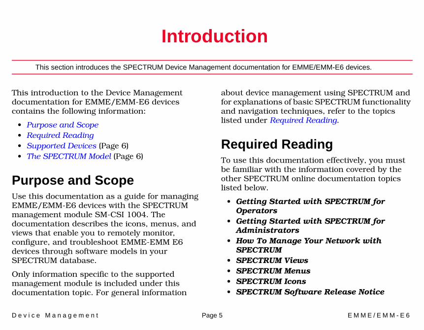
This introduction to the Device Management documentation for EMME/EMM-E6 devices contains the following information:
• Purpose and Scope• Required Reading• Supported Devices (Page 6)• The SPECTRUM Model (Page 6)
Purpose and ScopeUse this documentation as a guide for managing EMME/EMM-E6 devices with the SPECTRUM management module SM-CSI 1004. The documentation describes the icons, menus, and views that enable you to remotely monitor, configure, and troubleshoot EMME-EMM E6 devices through software models in your SPECTRUM database.
Only information specific to the supported management module is included under this documentation topic. For general information
about device management using SPECTRUM and for explanations of basic SPECTRUM functionality and navigation techniques, refer to the topics listed under Required Reading.
Required ReadingTo use this documentation effectively, you must be familiar with the information covered by the other SPECTRUM online documentation topics listed below.
• Getting Started with SPECTRUM for Operators
• Getting Started with SPECTRUM for Administrators
• How To Manage Your Network with SPECTRUM
• SPECTRUM Views• SPECTRUM Menus• SPECTRUM Icons • SPECTRUM Software Release Notice

I n t r o d u c t i o n S u p p o r t e d D e v i c e s
D e v i c e M a n a g e m e n t Page 6 E M M E / E M M - E 6
Supported Devices SPECTRUM management module SM-CSI 1004 supports the following devices:
• HubCSIEMME (EMME)• BRtrCSIEMM_E6 (EMM-E6)
The SPECTRUM ModelSPECTRUM uses these device model types, for modeling supported EMME/EMM-E6.
These models are represented in SpectroGRAPH views by Device icons. As Figure 1 shows, the appearance of the Device icon varies slightly depending on the kind of view it appears in.
Figure 1: Small and Large Device Icons
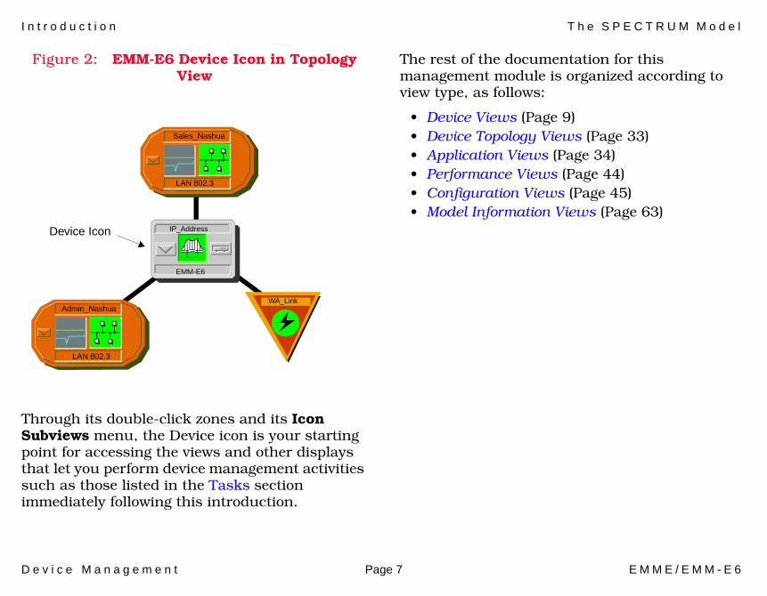
Figure 2 shows a portion of a Topology view in which the Device icon representing the EMM-E6 model appears surrounded by icons representing the network entities which the device connects—in this case two Ethernet LANs and an Off-Page Reference icon representing a Wide Area Link to a corporate network.
Large Device iconModel Name
Model Name Small Device icon appears inTopology, Device Topology,
appears in Device Topology,Location, andInterface Device views.
Application, and Container views.
EMM-E6
EMME
I n t r o d u c t i o n T h e S P E C T R U M M o d e l
D e v i c e M a n a g e m e n t Page 7 E M M E / E M M - E 6
Figure 2: EMM-E6 Device Icon in Topology View
Through its double-click zones and its Icon Subviews menu, the Device icon is your starting point for accessing the views and other displays that let you perform device management activities such as those listed in the Tasks section immediately following this introduction.
The rest of the documentation for this management module is organized according to view type, as follows:
• Device Views (Page 9)• Device Topology Views (Page 33)• Application Views (Page 34)• Performance Views (Page 44)• Configuration Views (Page 45)• Model Information Views (Page 63)
Admin_Nashua
LAN 802.3
Sales_Nashua
LAN 802.3
Device Icon
WA_Link
EMM-E6
IP_Address
D e v i c e M a n a g e m e n t Page 8 E M M E / E M M - E 6
Tasks
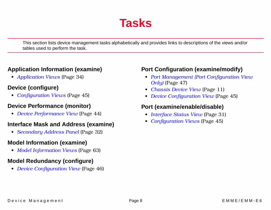
This section lists device management tasks alphabetically and provides links to descriptions of the views and/or tables used to perform the task.
Application Information (examine)• Application Views (Page 34)
Device (configure)• Configuration Views (Page 45)
Device Performance (monitor)• Device Performance View (Page 44)
Interface Mask and Address (examine)• Secondary Address Panel (Page 32)
Model Information (examine)• Model Information Views (Page 63)
Model Redundancy (configure)• Device Configuration View (Page 46)
Port Configuration (examine/modify)• Port Management (Port Configuration View
Only) (Page 47)• Chassis Device View (Page 11)• Device Configuration View (Page 45)
Port (examine/enable/disable)• Interface Status View (Page 31)• Configuration Views (Page 45)
D e v i c e M a n a g e m e n t Page 9 E M M E / E M M - E 6
Device Views
This section describes the Device views and subviews available for models of EMME/EMM-E6 devices in SPECTRUM.
Device views use icons and labels to represent the modeled device and its components, such as modules, ports, and applications. There are three types of Device views for EMME/EMM-E6 models.
• Interface Device View on Page 9• EMME Chassis Device View on Page 12• Physical Device View on Page 30
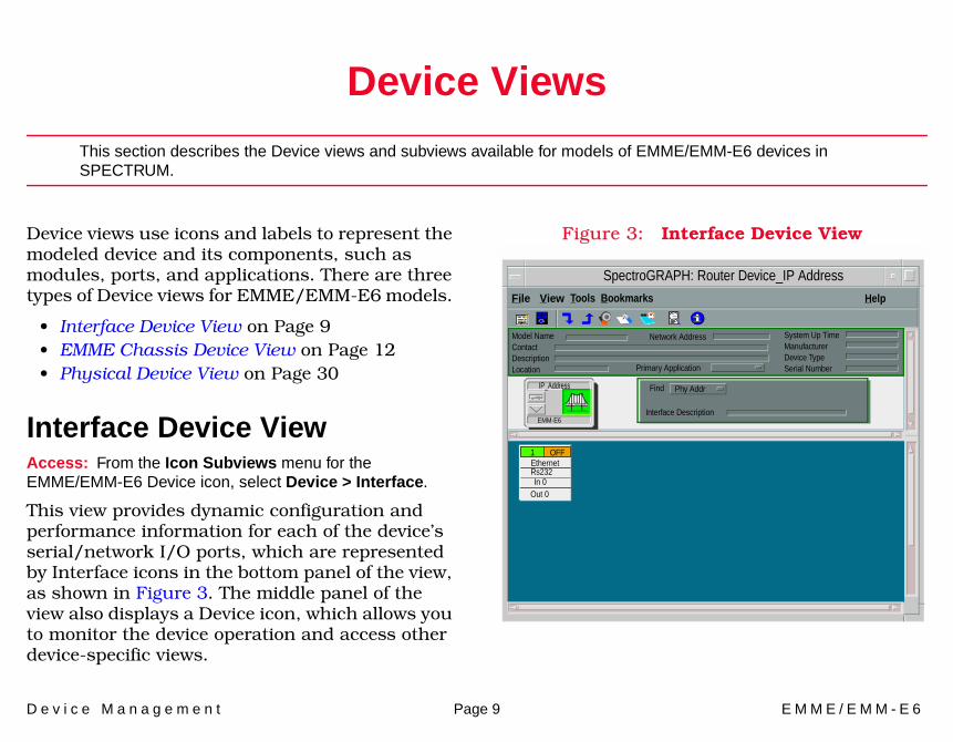
Interface Device ViewAccess: From the Icon Subviews menu for the EMME/EMM-E6 Device icon, select Device > Interface.
This view provides dynamic configuration and performance information for each of the device’s serial/network I/O ports, which are represented by Interface icons in the bottom panel of the view, as shown in Figure 3. The middle panel of the view also displays a Device icon, which allows you to monitor the device operation and access other device-specific views.
Figure 3: Interface Device View
SpectroGRAPH: Router Device_IP Address
File View Help
Model NameContactDescriptionLocation
System Up TimeManufacturerDevice TypeSerial Number
Network Address
Primary Application
Interface Description
Find Phy AddrIP_Address
EMM-E6
Ethernet1 OFF
Tools Bookmarks
Rs232In 0
Out 0
D e v i c e V i e w s I n t e r f a c e D e v i c e V i e w
D e v i c e M a n a g e m e n t Page 10 E M M E / E M M - E 6
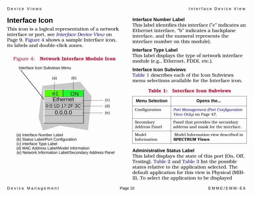
Interface IconThis icon is a logical representation of a network interface or port, see Interface Device View on Page 9. Figure 4 shows a sample Interface icon, its labels and double-click zones.
Figure 4: Network Interface Module Icon
Interface Number LabelThis label identifies this interface (”e” indicates an Ethernet interface, “b” indicates a backplane interface, and the numeral represents the interface number on this module).
Interface Type LabelThis label displays the type of network interface module (e.g., Ethernet, FDDI, etc.).
Interface Icon SubviewsTable 1 describes each of the Icon Subviews menu selections available for the Interface icon.
Administrative Status LabelThis label displays the state of this port (On, Off, Testing). Table 2 and Table 3 list the possible states relative to the application selected. The default application for this view is Physical (MIB-II). To select the application to be displayed
(c)
(d)
(e)
(a) (b)
e1Ethernet
0:0:1D:17:2F:3C0.0.0.0
Interface Icon Subviews Menu
(a) Interface Number Label(b) Status Label/Port Configuration(c) Interface Type Label(d) MAC Address Label/Model Information(e) Network Information Label/Secondary Address Panel
ONTable 1: Interface Icon Subviews
Menu Selection Opens the...
Configuration Port Management (Port Configuration View Only) on Page 47.
Secondary Address Panel
Panel that provides the secondary address and mask for the interface.
Model Information
Model Information view described in SPECTRUM Views.
D e v i c e V i e w s C h a s s i s D e v i c e V i e w
D e v i c e M a n a g e m e n t Page 11 E M M E / E M M - E 6
(Physical or Bridging), click the Filter menu button in the Interface Options panel. This label provides double-click access to Port Management (Port Configuration View Only) on Page 47.
MAC Address LabelThis label displays the physical address of the network interface module and accesses the CSI Port Model Information view described in SPECTRUM Views.
Network Information LabelThis label displays the network address, name, or subnet mask, which you select using the Interface Options panel. The default is network address. Double-click this label to access the Secondary Address Panel described in SPECTRUM Views.
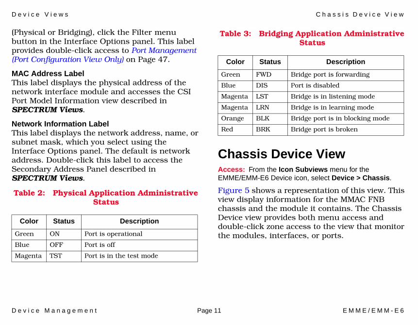
Table 2: Physical Application Administrative Status
Table 3: Bridging Application Administrative Status
Chassis Device ViewAccess: From the Icon Subviews menu for the EMME/EMM-E6 Device icon, select Device > Chassis.
Figure 5 shows a representation of this view. This view display information for the MMAC FNB chassis and the module it contains. The Chassis Device view provides both menu access and double-click zone access to the view that monitor the modules, interfaces, or ports.
Color Status Description
Green ON Port is operational
Blue OFF Port is off
Magenta TST Port is in the test mode
Color Status Description
Green FWD Bridge port is forwarding
Blue DIS Port is disabled
Magenta LST Bridge is in listening mode
Magenta LRN Bridge is in learning mode
Orange BLK Bridge port is in blocking mode
Red BRK Bridge port is broken
D e v i c e V i e w s E M M E / E M M - E 6 M o d u l e I c o n
D e v i c e M a n a g e m e n t Page 12 E M M E / E M M - E 6
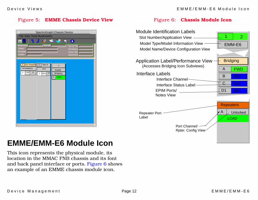
Figure 5: EMME Chassis Device View
EMME/EMM-E6 Module IconThis icon represents the physical module, its location in the MMAC FNB chassis and its font and back panel interface or ports. Figure 6 shows an example of an EMME chassis module icon.
Figure 6: Chassis Module Icon
Model Name
Contact
Description
Location
Net Addr Sys Up Time
Manufacturer
Device Type
Serial Number
File View Tools BookmarksSpectroGraph:Chassis Device
3 ISO ReptrB
TPXMIM22
1 LNK 0 1 SEG 0
TPT
2 Net A 1
EMME
Bridging
A FWD
EMM-E6
A FWD
B DIS
C DIS
D1 DIS
Bridging
Model Type/Model Information ViewModel Name/Device Configuration View
Slot Number/Application ViewModule Identification Labels
Application Label/Performance View
Interface Channel
Interface Status Label
(Accesses Bridging Icon Subviews)
Interface Labels
Unlocked
1 2
EPIM Ports/Notes View
Repeaters
A
LOAD
Repeater PortLabel
Port Channel/Rpter. Config View
D e v i c e V i e w s E M M E / E M M - E 6 M o d u l e I c o n
D e v i c e M a n a g e m e n t Page 13 E M M E / E M M - E 6
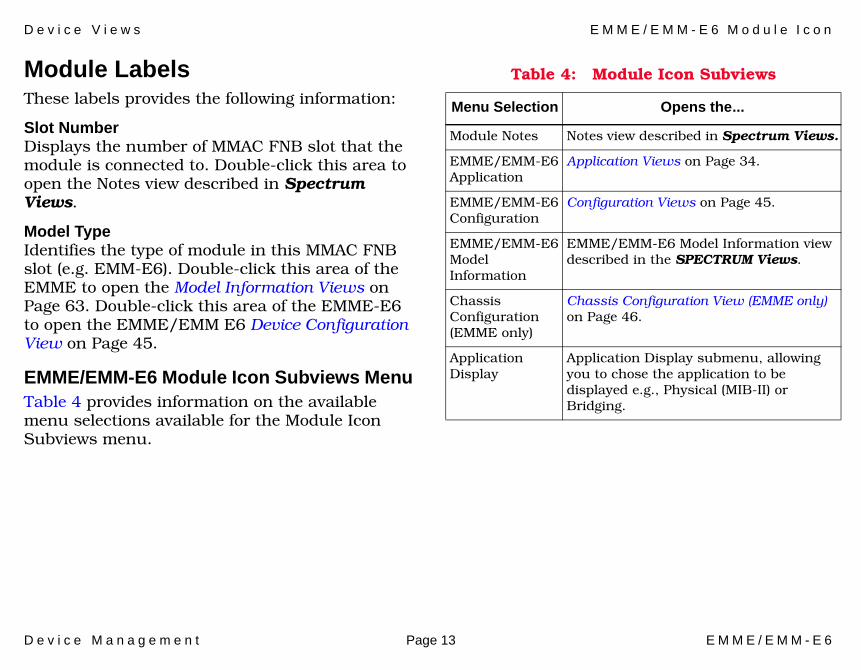
Module LabelsThese labels provides the following information:
Slot NumberDisplays the number of MMAC FNB slot that the module is connected to. Double-click this area to open the Notes view described in Spectrum Views.
Model TypeIdentifies the type of module in this MMAC FNB slot (e.g. EMM-E6). Double-click this area of the EMME to open the Model Information Views on Page 63. Double-click this area of the EMME-E6 to open the EMME/EMM E6 Device Configuration View on Page 45.
EMME/EMM-E6 Module Icon Subviews MenuTable 4 provides information on the available menu selections available for the Module Icon Subviews menu.
Table 4: Module Icon Subviews
Menu Selection Opens the...
Module Notes Notes view described in Spectrum Views.
EMME/EMM-E6 Application
Application Views on Page 34.
EMME/EMM-E6 Configuration
Configuration Views on Page 45.
EMME/EMM-E6 Model Information
EMME/EMM-E6 Model Information view described in the SPECTRUM Views.
Chassis Configuration (EMME only)
Chassis Configuration View (EMME only) on Page 46.
Application Display
Application Display submenu, allowing you to chose the application to be displayed e.g., Physical (MIB-II) or Bridging.
D e v i c e V i e w s E M M E / E M M - E 6 M o d u l e I c o n
D e v i c e M a n a g e m e n t Page 14 E M M E / E M M - E 6
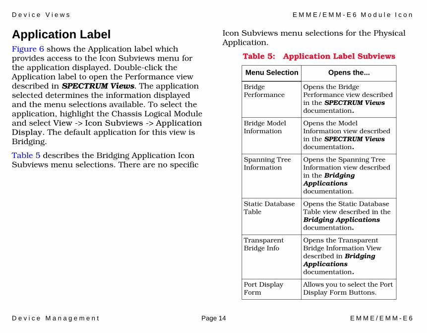
Application LabelFigure 6 shows the Application label which provides access to the Icon Subviews menu for the application displayed. Double-click the Application label to open the Performance view described in SPECTRUM Views. The application selected determines the information displayed and the menu selections available. To select the application, highlight the Chassis Logical Module and select View -> Icon Subviews -> Application Display. The default application for this view is Bridging.
Table 5 describes the Bridging Application Icon Subviews menu selections. There are no specific
Icon Subviews menu selections for the Physical Application.
Table 5: Application Label Subviews
Menu Selection Opens the...
Bridge Performance
Opens the Bridge Performance view described in the SPECTRUM Views documentation.
Bridge Model Information
Opens the Model Information view described in the SPECTRUM Views documentation.
Spanning Tree Information
Opens the Spanning Tree Information view described in the Bridging Applications documentation.
Static Database Table
Opens the Static Database Table view described in the Bridging Applications documentation.
Transparent Bridge Info
Opens the Transparent Bridge Information View described in Bridging Applications documentation.
Port Display Form
Allows you to select the Port Display Form Buttons.
D e v i c e V i e w s E M M E / E M M - E 6 M o d u l e I c o n
D e v i c e M a n a g e m e n t Page 15 E M M E / E M M - E 6
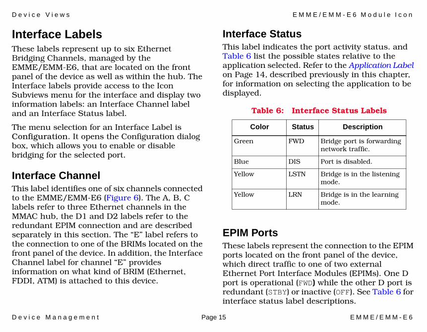
Interface LabelsThese labels represent up to six Ethernet Bridging Channels, managed by the EMME/EMM-E6, that are located on the front panel of the device as well as within the hub. The Interface labels provide access to the Icon Subviews menu for the interface and display two information labels: an Interface Channel label and an Interface Status label.
The menu selection for an Interface Label is Configuration. It opens the Configuration dialog box, which allows you to enable or disable bridging for the selected port.
Interface ChannelThis label identifies one of six channels connected to the EMME/EMM-E6 (Figure 6). The A, B, C labels refer to three Ethernet channels in the MMAC hub, the D1 and D2 labels refer to the redundant EPIM connection and are described separately in this section. The “E” label refers to the connection to one of the BRIMs located on the front panel of the device. In addition, the Interface Channel label for channel “E” provides information on what kind of BRIM (Ethernet, FDDI, ATM) is attached to this device.
Interface StatusThis label indicates the port activity status. and Table 6 list the possible states relative to the application selected. Refer to the Application Label on Page 14, described previously in this chapter, for information on selecting the application to be displayed.
EPIM PortsThese labels represent the connection to the EPIM ports located on the front panel of the device, which direct traffic to one of two external Ethernet Port Interface Modules (EPIMs). One D port is operational (FWD) while the other D port is redundant (STBY) or inactive (OFF). See Table 6 for interface status label descriptions.
Table 6: Interface Status Labels
Color Status Description
Green FWD Bridge port is forwarding network traffic.
Blue DIS Port is disabled.
Yellow LSTN Bridge is in the listening mode.
Yellow LRN Bridge is in the learning mode.

D e v i c e V i e w s E M M E / E M M - E 6 M o d u l e I c o n
D e v i c e M a n a g e m e n t Page 16 E M M E / E M M - E 6
Table 7 lists the Subviews menu selections available from this label.
BRIM PortThis label represents the connection to one of two BRIM ports located on the front panel of the EMME/EMM-E6, which direct traffic to the optional external Bridge/Router Interface Module (BRIM). A second interface provided by the other BRIM port (forming channel F) will be implemented in the future.
Repeater LabelThis label represents the Repeater application that allows for transfer of information between the repeaters in the MMAC chassis and EMME/EMM-E6. The repeater label provides
access to the Icon Subviews menu for this application. Table 8 lists specific Subviews menu selections for the Repeater Label.
Table 7: AUI Port Subviews Menu
Menu Selection Opens the...
Notes Notes view described in Spectrum Views.
Configuration The Configuration dialog box, which allows you to enable or disable bridging for the selected port.
Table 8: Repeater Icon Subviews Menu
Menu Selection Opens the...
Repeater Notes Notes view described in SPECTRUM Views.
Repeater Events Event Log window described in SPECTRUM Views.
Repeater Alarms Alarm Manager view described in SPECTRUM Views.
Repeater Performance
Performance view described in SPECTRUM Views.
Repeater Frame & Error Breakdown
Repeater Frame & Error Breakdown View on Page 17 described later in this chapter.
Repeater Frame Size & Protocols
Repeater Frame Size & Protocols View on Page 18 described later in this chapter.
Repeater Configuration
Repeater Configuration View on Page 51.
Repeater Model Information
Repeater Model Information view described in SPECTRUM Views.

D e v i c e V i e w s E M M E / E M M - E 6 M o d u l e I c o n
D e v i c e M a n a g e m e n t Page 17 E M M E / E M M - E 6
Repeater Frame & Error Breakdown ViewAccess: From the Icon Subviews menu for the Chassis Device Repeater Label, select Repeater Frame & Error Breakdown.
This view displays statistics for a selected port. This view is divided into two areas which provide the following separate performance information:
• Frame Breakdown• Error Breakdown
Each area includes the pie chart providing a visual representation of the numerical statistics. In addition, the Repeater Frame and Error Breakdown view supplies the following presentation modes, affecting the way data is displayed in this view:
TotalAllows you to display the current statistical information for all items contributing to the total value.
DeltaAllows you to display the difference between the previously polled values and the current value of every item contributing to the total.
AccumAllows you to view the accumulated statistical information for all items since the Accum button was last selected.
Select this button to restart the counter. The values will continue to accumulate until clear is selected or another presentation mode is chosen.
Pie ChartWhen Total is selected, the pie chart displays the current statistical information for all items contributing to the total value. When Delta is selected, the pie graph is used to compare the difference between the previously polled value and the current value of all items. When Accum is chosen, the pie chart provides the statistics for all items accumulated since the Accum button was selected.
Frame BreakdownDisplays the breakdown of all the frames transmitted and received through the selected
Clear
Note:Note:
Selecting Total, Delta or Accum affects the numerical, as well as graphical representation of every item contributing to the total.
D e v i c e V i e w s E M M E / E M M - E 6 M o d u l e I c o n
D e v i c e M a n a g e m e n t Page 18 E M M E / E M M - E 6
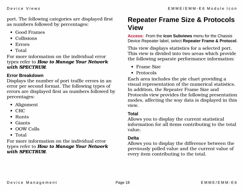
port. The following categories are displayed first as numbers followed by percentages:
• Good Frames• Collisions• Errors• Total
For more information on the individual error types refer to How to Manage Your Network with SPECTRUM.
Error Breakdown Displays the number of port traffic errors in an error per second format. The following types of errors are displayed first as numbers followed by percentages:
• Alignment• CRC• Runts• Giants• OOW Colls• Total
For more information on the individual error types refer to How to Manage Your Network with SPECTRUM.
Repeater Frame Size & Protocols ViewAccess: From the Icon Subviews menu for the Chassis Device Repeater label, select Repeater Frame & Protocol.
This view displays statistics for a selected port. This view is divided into two areas which provide the following separate performance information:
• Frame Size• Protocols
Each area includes the pie chart providing a visual representation of the numerical statistics. In addition, the Repeater Frame Size and Protocols view provides the following presentation modes, affecting the way data is displayed in this view.
TotalAllows you to display the current statistical information for all items contributing to the total value.
DeltaAllows you to display the difference between the previously polled value and the current value of every item contributing to the total.

D e v i c e V i e w s E M M E / E M M - E 6 M o d u l e I c o n
D e v i c e M a n a g e m e n t Page 19 E M M E / E M M - E 6
AccumAllows you to view the accumulated statistical information for all items since the Accum button was last selected.
ClearRestarts the counter. The values for all items will continue to accumulate until clear is selected or another presentation mode is chosen.
Frame SizeDisplays a number signifying how many frames from a selected port are of a certain size. This number is displayed as a numerical value and as percentage of the total frames transmitted and received. The view provides the following frame size categories:
• Runts
• 64 -127 Bytes
• 128 - 255 Bytes
• 256 - 511 Bytes
• 512 - 1023 Bytes
• Giants
For more information on the individual error types refer to How to Manage Your Network with SPECTRUM.
ProtocolsDisplays a number of particular protocol types generated for a selected port. The following protocols are displayed first as numbers followed by percentages:
• IP• OSI• DECnet• XNS• Novel• AppleTalk• Banyan• Ctron• Other
Repeater Port LabelThis label represents the bridging channel connecting the EMME/EMM-E6 to a MIM located in the hub.
Note:Note:
Selecting Total, Delta, or Accum affects the numerical, as well as graphical representation of every item contributing to the total.
D e v i c e V i e w s E M M E / E M M - E 6 M o d u l e I c o n
D e v i c e M a n a g e m e n t Page 20 E M M E / E M M - E 6
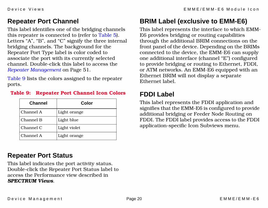
Repeater Port ChannelThis label identifies one of the bridging channels this repeater is connected to (refer to Table 5). Letters “A”, “B”, and “C” signify the three internal bridging channels. The background for the Repeater Port Type label is color coded to associate the port with its currently selected channel. Double-click this label to access the Repeater Management on Page 51.
Table 9 lists the colors assigned to the repeater ports.
Repeater Port StatusThis label indicates the port activity status. Double-click the Repeater Port Status label to access the Performance view described in SPECTRUM Views.
BRIM Label (exclusive to EMM-E6)This label represents the interface to which EMM-E6 provides bridging or routing capabilities through the additional BRIM connections on the front panel of the device. Depending on the BRIMs connected to the device, the EMM-E6 can supply one additional interface (channel “E”) configured to provide bridging or routing to Ethernet, FDDI, or ATM networks. An EMM-E6 equipped with an Ethernet BRIM will not display a separate Ethernet label.
FDDI LabelThis label represents the FDDI application and signifies that the EMM-E6 is configured to provide additional bridging or Feeder Node Routing on FDDI. The FDDI label provides access to the FDDI application-specific Icon Subviews menu.
Table 9: Repeater Port Channel Icon Colors
Channel Color
Channel A Light orange
Channel B Light blue
Channel C Light violet
Channel A Light orange
D e v i c e V i e w s E M M E / E M M - E 6 M o d u l e I c o n
D e v i c e M a n a g e m e n t Page 21 E M M E / E M M - E 6
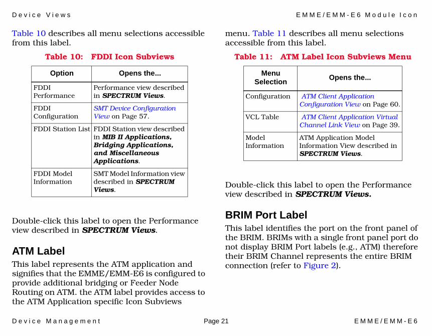
Table 10 describes all menu selections accessible from this label.
Double-click this label to open the Performance view described in SPECTRUM Views.
ATM LabelThis label represents the ATM application and signifies that the EMME/EMM-E6 is configured to provide additional bridging or Feeder Node Routing on ATM. the ATM label provides access to the ATM Application specific Icon Subviews
menu. Table 11 describes all menu selections accessible from this label.
Double-click this label to open the Performance view described in SPECTRUM Views.
BRIM Port LabelThis label identifies the port on the front panel of the BRIM. BRIMs with a single front panel port do not display BRIM Port labels (e.g., ATM) therefore their BRIM Channel represents the entire BRIM connection (refer to Figure 2).
Table 10: FDDI Icon Subviews
Option Opens the...
FDDI Performance
Performance view described in SPECTRUM Views.
FDDI Configuration
SMT Device Configuration View on Page 57.
FDDI Station List FDDI Station view described in MIB II Applications, Bridging Applications, and Miscellaneous Applications.
FDDI Model Information
SMT Model Information view described in SPECTRUM Views.
Table 11: ATM Label Icon Subviews Menu
Menu Selection
Opens the...
Configuration ATM Client Application Configuration View on Page 60.
VCL Table ATM Client Application Virtual Channel Link View on Page 39.
Model Information
ATM Application Model Information View described in SPECTRUM Views.

D e v i c e V i e w s E M M E / E M M - E 6 M o d u l e I c o n
D e v i c e M a n a g e m e n t Page 22 E M M E / E M M - E 6
The BRIM Port label provides access to the Icon Subviews Menu described in Table 12.
BRIM Port Type LabelThis label consists of two fields: the number field and the letter field. The number field displays the number assigned to this BRIM port. The letter field displays the type of this port.
Double-click the number field of the BRIM Port Type label to access the Notes view described in SPECTRUM Views.
BRIM Port Status LabelThis label indicates the port activity status. All possible states and their color definitions are described in Table 13.
MIM IconThis icon represents a Media Interface Module (MIM). There are two basic types of MIMs that can be managed by the EMME/EMM-E6: Repeater MIMs (RMIMs) and non-repeater MIMs.
The EMME/EMM-E6 manages the RMIMs located in the MMAC chassis through Ethernet channels B, and C. RMIMs can repeat packets autonomously without channeling them through the EMME/EMM-E6. The members of the RMIM family designed to work with the EMME/EMM-E6 are: FORMIM, CXRMIM, TPRMIM, and TPXMIM.
Table 12: BRIM Port Label Subviews Menu
Menu Selection
Opens the...
Port Notes Notes view described in SPECTRUM Views.
Enable/Disable Port
A dialog box which allows you to enable or disable a selected port.
Port Configuration View
The Port Management (Port Configuration View Only) on Page 47.
Table 13: BRIM Port Status Descriptions
Color State Description
Green ACT active
Blue DIS disabled
Yellow CON connecting
Red SBY standby
D e v i c e V i e w s E M M E / E M M - E 6 M o d u l e I c o n
D e v i c e M a n a g e m e n t Page 23 E M M E / E M M - E 6
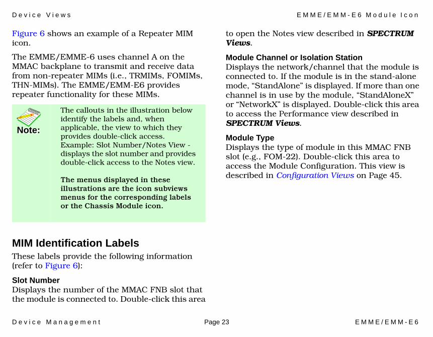
Figure 6 shows an example of a Repeater MIM icon.
The EMME/EMME-6 uses channel A on the MMAC backplane to transmit and receive data from non-repeater MIMs (i.e., TRMIMs, FOMIMs, THN-MIMs). The EMME/EMM-E6 provides repeater functionality for these MIMs.
MIM Identification LabelsThese labels provide the following information (refer to Figure 6):
Slot NumberDisplays the number of the MMAC FNB slot that the module is connected to. Double-click this area
to open the Notes view described in SPECTRUM Views.
Module Channel or Isolation StationDisplays the network/channel that the module is connected to. If the module is in the stand-alone mode, “StandAlone” is displayed. If more than one channel is in use by the module, “StandAloneX” or “NetworkX” is displayed. Double-click this area to access the Performance view described in SPECTRUM Views.
Module TypeDisplays the type of module in this MMAC FNB slot (e.g., FOM-22). Double-click this area to access the Module Configuration. This view is described in Configuration Views on Page 45.
Note:Note:
The callouts in the illustration below identify the labels and, when applicable, the view to which they provides double-click access. Example: Slot Number/Notes View - displays the slot number and provides double-click access to the Notes view.
The menus displayed in these illustrations are the icon subviews menus for the corresponding labels or the Chassis Module icon.

D e v i c e V i e w s E M M E / E M M - E 6 M o d u l e I c o n
D e v i c e M a n a g e m e n t Page 24 E M M E / E M M - E 6
MIM Icon Subviews MenuTable 14 describes each of the module-specific Icon Subviews menu selections available for the Repeater module.
Change Module Channel View (RMIMs only)Access: From the Icon Subviews menu or the Repeater MIM on the Chassis Device icon, select Repeater > Change Module Channel.
This view allows you to change the FNB channel used by a port to communicate with the EMME/EMM-E6. It also allows you to reconfigure the module to a stand-alone mode if it provides its own repeater functionality.
When configured to operate on channels B or C, the Repeater MIM provides its own repeating; when operating on channel A, its ports depend on the EMME/EMM-E6 for repeater functionality. Change Module Channel view provides the following information and fields:
Module NumberDisplays the slot number where the selected RMIM is located. The RMIM located in this slot will be the only one affected by the configuration changes.
Module ConnectionAllows you to chose the appropriate backplane channel or mode. The possible selections are:
Table 14: MIM Icon Subviews Menu
Menu Selection Opens the...
Module Notes Notes view described in SPECTRUM Views.
Serial Number Dialog box allowing you to enter or alter the serial number for the selected module.
Module Configuration
Module and Port Configuration Views on Page 47.
Module Performance
Performance view described in SPECTRUM Views.
Module DevTop View
Device Topology view described in SPECTRUM Views.
Repeater Opens a submenu described in Table 8.
Module Frame Size & Protocols
Opens the Repeater Frame Size & Protocols View on Page 18.
D e v i c e V i e w s E M M E / E M M - E 6 M o d u l e I c o n
D e v i c e M a n a g e m e n t Page 25 E M M E / E M M - E 6
Channel B, Channel C, Stand_Alone, and Channel_X.
The Stand_Alone option can be applied to all ports configured to use Channels B or C. Any ports that are configured to operate on Channel A cannot be switched to the Stand_Alone mode. For more information, see Creating an Isolated Repeater on Page 37.
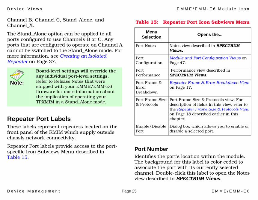
Repeater Port LabelsThese labels represent repeaters located on the front panel of the RMIM which supply outside chassis network connectivity.
Repeater Port labels provide access to the port-specific Icon Subviews Menu described in Table 15.
Port NumberIdentifies the port’s location within the module. The background for this label is color coded to associate the port with its currently selected channel. Double-click this label to open the Notes view described in SPECTRUM Views.
Note:Note:
Board-level settings will override the any individual port-level settings.Refer to Release Notes that were shipped with your EMME/EMM-E6 firmware for more information about the implication of operating your TPXMIM in a Stand_Alone mode.
Table 15: Repeater Port Icon Subviews Menu
Menu Selection Opens the...
Port Notes Notes view described in SPECTRUM Views.
Port Configuration
Module and Port Configuration Views on Page 47.
Port Performance
Performance view described in SPECTRUM Views.
Port Frame & Error Breakdown
Repeater Frame & Error Breakdown View on Page 17.
Port Frame Size & Protocols
Port Frame Size & Protocols view. For description of fields in this view, refer to the Repeater Frame Size & Protocols View on Page 18 described earlier in this chapter.
Enable/Disable Port
Dialog box which allows you to enable or disable a selected port.
D e v i c e V i e w s E M M E / E M M - E 6 M o d u l e I c o n
D e v i c e M a n a g e m e n t Page 26 E M M E / E M M - E 6
Port StatusDescribes the port activity status.
Port StatisticsDisplays the number of frames (packets) transmitted or received by this port.
TPXMIMThe EMME/ EMM-E6 also supports Cabletron’s family of Twisted Pair Switching Media Interface Modules (TPXMIMs). The TPXMIM-20, -22, -33 and -34 are a series of port assignment modules designed specifically for Cabletron’s MMAC FNB hubs equipped with the EMME/EMM-E6. TPXMIM permits the entire board (bank switching) or each individual port (the port assignment) to be assigned to any of the three Ethernet channels A, B, and C on the MMAC FNB backplane. This way the unnecessary traffic across the bridge can be eliminated. The TPXMIM gives you an option of reassigning ports to
different channels right at the management station without having to move the cable.
Note:Note:
The callouts in the illustration below identify the label and, when applicable, the view to which they provide double-click access. Example: Port Number/Notes View - displays the sport number and provides double-click access to the Notes view.

D e v i c e V i e w s E M M E / E M M - E 6 M o d u l e I c o n
D e v i c e M a n a g e m e n t Page 27 E M M E / E M M - E 6
Figure 7: TPXMIM Icon TPXMIM Identification LabelsThese labels provide the following information:
Slot NumberDisplays the number of the MMAC-FNB slot that the module is connected to. Double-click this area to open the Notes view described in SPECTRUM Views.
Module Channel or Isolation StationDisplays the channel that the module is connected to. If the module is in the stand-alone mode, “StandAlone” is displayed. If more than one channel is in use by the module, “StandAloneX” or “NetworkX” is displayed.
Module TypeDisplays the type of module in this MMAC FNB slot (e.g.,TXMIM 22).
TPXMIM Icon Subviews MenuTable 16 describes each of the module-specific Icon Subviews menu selections available for the
5 Network B
TPXMIM22
2 LNK
3 LNK
4 LNK
567 LNK
8 LNK
Slot Number
Module Type
Port Number/
Port Status/
Module Channel
Port Statistics/
01
or Isolation Station
CloseCtrl +cNavigateAlarmsPerformanceNotes...UtilitiesZoomModule Notes
CloseCtrl +cNavigateAlarmsPerformanceNotes...UtilitiesZoomPort NotesPort ConfigurationPort PerformancePort Frame and Error
910 2
1112
LNK
LNK
LNK
LNK
LNK
13 LNK
141516
LNK
LNK
LNK
ON
Network ANetwork B Module Configuration
Module PerformanceModule Frame & Error
Notes View
Port Config. View
Performance View
EPIM Port
0
0
0
0
0
0
0
0
0
0
0
0
0
0
ModuleIdentificationLabels
TPXMIM22Port Labels
D e v i c e V i e w s E M M E / E M M - E 6 M o d u l e I c o n
D e v i c e M a n a g e m e n t Page 28 E M M E / E M M - E 6
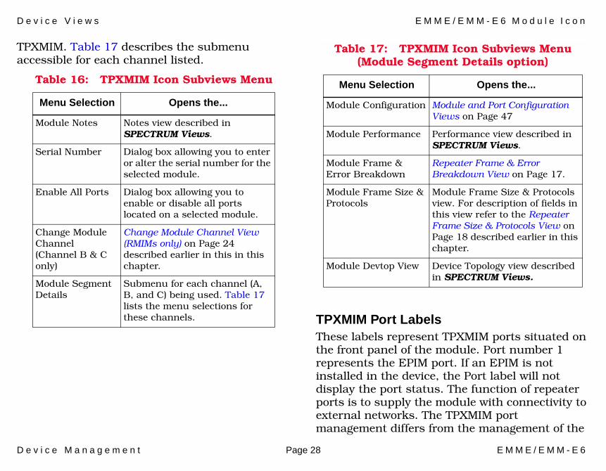
TPXMIM. Table 17 describes the submenu accessible for each channel listed.
TPXMIM Port LabelsThese labels represent TPXMIM ports situated on the front panel of the module. Port number 1 represents the EPIM port. If an EPIM is not installed in the device, the Port label will not display the port status. The function of repeater ports is to supply the module with connectivity to external networks. The TPXMIM port management differs from the management of the
Table 16: TPXMIM Icon Subviews Menu
Menu Selection Opens the...
Module Notes Notes view described in SPECTRUM Views.
Serial Number Dialog box allowing you to enter or alter the serial number for the selected module.
Enable All Ports Dialog box allowing you to enable or disable all ports located on a selected module.
Change Module Channel(Channel B & C only)
Change Module Channel View (RMIMs only) on Page 24 described earlier in this in this chapter.
Module Segment Details
Submenu for each channel (A, B, and C) being used. Table 17 lists the menu selections for these channels.
Table 17: TPXMIM Icon Subviews Menu (Module Segment Details option)
Menu Selection Opens the...
Module Configuration Module and Port Configuration Views on Page 47
Module Performance Performance view described in SPECTRUM Views.
Module Frame & Error Breakdown
Repeater Frame & Error Breakdown View on Page 17.
Module Frame Size & Protocols
Module Frame Size & Protocols view. For description of fields in this view refer to the Repeater Frame Size & Protocols View on Page 18 described earlier in this chapter.
Module Devtop View Device Topology view described in SPECTRUM Views.

D e v i c e V i e w s E M M E / E M M - E 6 M o d u l e I c o n
D e v i c e M a n a g e m e n t Page 29 E M M E / E M M - E 6
ordinary MIM ports because every TPXMIM port can be assigned to any of the three Ethernet channels on the MMAC FNB backplane.
TPXMIM Port labels provide access to the port-specific Icon Subviews menu described in Table 18.
Change Port Channel ViewAccess: From the Icon Subviews menu for the TPXMIM Chassis Device icon, select Change Port Channel.
This view allows you to reassign the FNB channel used by a selected port to communicate within the MMAC FNB chassis. It also allows you to reconfigure a port to a stand-alone mode.
When configured to operate on channels B or C, the TPXMIM provides its own repeating, when operating on channel A, TPXMIM ports depend on the EMME/EMM-E6 for repeater functionality. All TPXMIM ports default to channel B when first installed. Change Port Channel view provides the following fields:
Module NumberDisplays the slot number where the TPXMIM containing a selected port is located.
Table 18: TPXMIM Port Icon Subviews Menu
Menu Selection Opens the...
Port Notes Notes view described in the SPECTRUM Views.
Port Configuration
Port Management (Port Configuration View Only) on Page 47.
Port Performance Performance view described in SPECTRUM Views.
Port Frame & Error Breakdown
Port Frame & Error Breakdown view. For description of fields in this view, see the Repeater Frame & Error Breakdown View on Page 17 described earlier in this chapter.
Port Frame Size & Protocols
Port Frame Size & Protocols view. For description of fields in this view, see the Repeater Frame Size & Protocols View on Page 18 described earlier in this chapter.
Enable/Disable Dialog box which allows you to enable or disable a selected port.
Change Port Channel
Change Port Channel View on Page 29 described later in this chapter.
Table 18: TPXMIM Port Icon Subviews Menu
Menu Selection Opens the...

D e v i c e V i e w s P h y s i c a l D e v i c e V i e w
D e v i c e M a n a g e m e n t Page 30 E M M E / E M M - E 6
Port NumberDisplays the number of a selected port that will be affected by the configuration changes.
Port ConnectionAllows you to choose the appropriate backplane channel from the pull-down menu. The pull-down menu includes the following selections: Channel A, Channel B, and Channel C. Individual ports cannot be placed in stand-alone mode via this menu.
Port NumberThis label identifies the port location within the module. The background for this label is color coded to associate the port with its currently selected channel. Double-click this label to open the Notes view described in SPECTRUM Views.
Port StatusThis label describes the port activity status. Double-click this label to access the Port Configuration view described in Configuration Views.
Port StatisticsDisplays the number of frames (packets) transmitted or received by this port. Double-click this label to access the Performance view described in SPECTRUM Views.
Physical Device ViewAccess: From the Icon Subviews menu for the EMME/EMM-6 Device Icon, select > Device > Physical View.
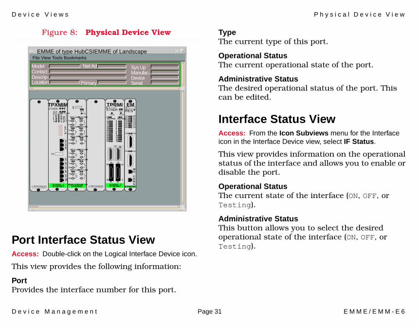
This view shows a static image of all slots in the MMAC FNB Chassis and devices placed in them, including EMME/EMM-E6. Figure 8 shows an example of the Physical Device view.
Note:Note:
To place only selected ports in stand-alone mode, configure all other ports so that they are connected to Channel A: those ports will remain connected to Channel A when stand-alone mode is implemented, and only those ports connected to channels B or C will be put in stand-alone mode.
D e v i c e V i e w s P h y s i c a l D e v i c e V i e w
D e v i c e M a n a g e m e n t Page 31 E M M E / E M M - E 6
Figure 8: Physical Device View
Port Interface Status ViewAccess: Double-click on the Logical Interface Device icon.
This view provides the following information:
PortProvides the interface number for this port.
TypeThe current type of this port.
Operational StatusThe current operational state of the port.
Administrative StatusThe desired operational status of the port. This can be edited.
Interface Status ViewAccess: From the Icon Subviews menu for the Interface icon in the Interface Device view, select IF Status.
This view provides information on the operational status of the interface and allows you to enable or disable the port.
Operational StatusThe current state of the interface (ON, OFF, or Testing).
Administrative StatusThis button allows you to select the desired operational state of the interface (ON, OFF, or Testing).
File View Tools BookmarksEMME of type HubCSIEMME of Landscape
Model ContactDescrip-Location
Net Adr Sys Up Manufac-Device Serial
EMSRESDKSASBRARBRCRD
ERSCSDCACBCCCD
DM FM
DM FM
CONS
MO
ETHERNET
TPRMISETHER- B C
CLNCLN114AUI POKAUI POK
2345678910111213
151617181920212223242526
13
2
26
15
10 BASE - TETHERNET
SB C
CL
RCV LNKRCV LNK
17TX
RXRCV LNKRCV LNK
28TX
RXRCV LNKRCV LNK
39TX
RX
RCV LNKRCV LNK
410TX
RXRCV LNKRCV LNK
511TX
RXRCV LNKRCV LNK
612TX
RX
FDIAL/10BASE - FFETHERNET
TPXMIM
SN
ETHER-A B C
RCV LNKCLN
RCV LNK12345
678910
EPIM
2X3X4X
5X6X7X8X
9X10X
10 BASE - TETHERNET
Primary

D e v i c e V i e w s P h y s i c a l D e v i c e V i e w
D e v i c e M a n a g e m e n t Page 32 E M M E / E M M - E 6
Secondary Address PanelAccess: From the Icon Subviews menu for the Interface icon in the Interface Device view, select Secondary Address Panel.
This panel provides a table of IP addresses and masks obtained from the Address Translation table within the device’s firmware. You can change the current address displayed in the IP Address field by selecting an entry from the table in this panel and clicking the Update button.
D e v i c e M a n a g e m e n t Page 33 E M M E / E M M - E 6
Device Topology Views
This section provides a brief description of the Device Topology view available for models of EMME/EMM-E6 devices in SPECTRUM.
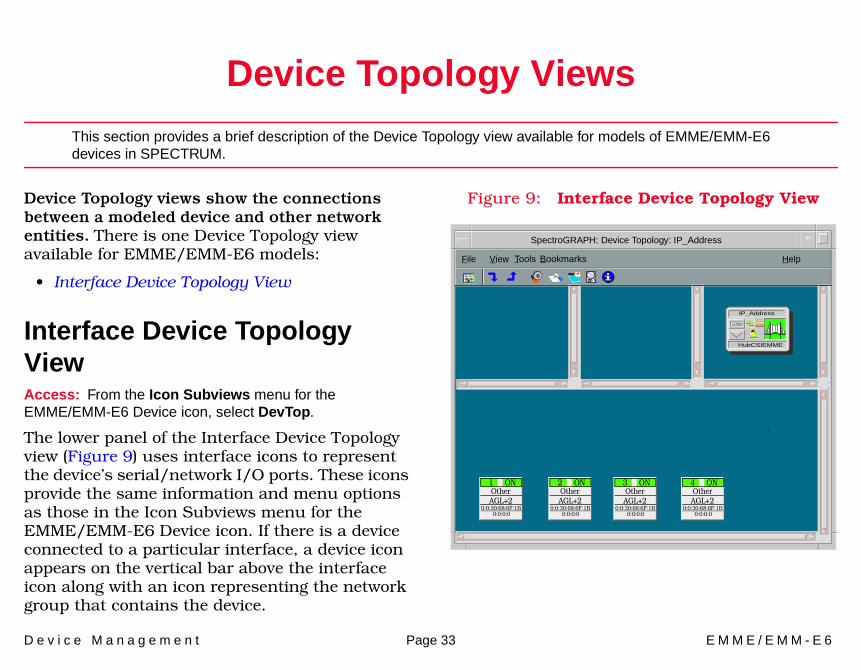
Device Topology views show the connections between a modeled device and other network entities. There is one Device Topology view available for EMME/EMM-E6 models:
• Interface Device Topology View
Interface Device Topology ViewAccess: From the Icon Subviews menu for the EMME/EMM-E6 Device icon, select DevTop.
The lower panel of the Interface Device Topology view (Figure 9) uses interface icons to represent the device’s serial/network I/O ports. These icons provide the same information and menu options as those in the Icon Subviews menu for the EMME/EMM-E6 Device icon. If there is a device connected to a particular interface, a device icon appears on the vertical bar above the interface icon along with an icon representing the network group that contains the device.
Figure 9: Interface Device Topology View
SpectroGRAPH: Device Topology: IP_Address
IP_Address
HubCSIEMME
File View Help
OtherAGL+2
1 ON
0:0:30:68:6F:1B0:0:0:0
l
Tools Bookmarks
OtherAGL+2
2 ON
0:0:30:68:6F:1B0:0:0:0
OtherAGL+2
4 ON
0:0:30:68:6F:1B0:0:0:0
OtherAGL+2
3 ON
0:0:30:68:6F:1B0:0:0:0
D e v i c e M a n a g e m e n t Page 34 E M M E / E M M - E 6
Application Views
This section describes the main Application view and the associated application-specific subviews available for models of EMME/EMM-E6 devices in SPECTRUM.
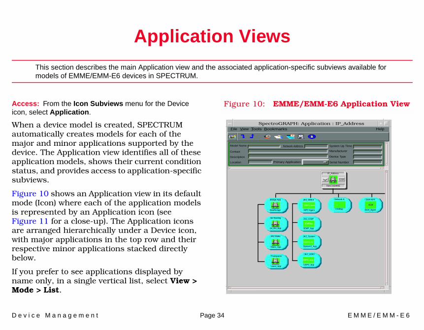
Access: From the Icon Subviews menu for the Device icon, select Application.
When a device model is created, SPECTRUM automatically creates models for each of the major and minor applications supported by the device. The Application view identifies all of these application models, shows their current condition status, and provides access to application-specific subviews.
Figure 10 shows an Application view in its default mode (Icon) where each of the application models is represented by an Application icon (see Figure 11 for a close-up). The Application icons are arranged hierarchically under a Device icon, with major applications in the top row and their respective minor applications stacked directly below.
If you prefer to see applications displayed by name only, in a single vertical list, select View > Mode > List.
Figure 10: EMME/EMM-E6 Application View
Model Name
Contact
Description
Location Primary Application
System Up Time
Manufacturer
Device Type
Serial Number
Network Address
File View Help
JK2_MIB-II
MP2-Agent
JK2_ICMP
ICMP_App
Bridge App
be Routing
JK2 Static
Transparen
GenRtrApp
ce_Rtr_App
Static_App
arent_App
SNMP2_Agent
ICMPApp
System2_App
UDP2_App
JK2_System
JK2_UDP2
System2_App
UDP2_App
SpectroGRAPH: Application : IP_Address Tools Bookmarks
IP_Address
HubCSIEMME
Network A
CSIRep
DLM APP
DLM_Agent
DLM
A p p l i c a t i o n V i e w s A p p l i c a t i o n I c o n s
D e v i c e M a n a g e m e n t Page 35 E M M E / E M M - E 6
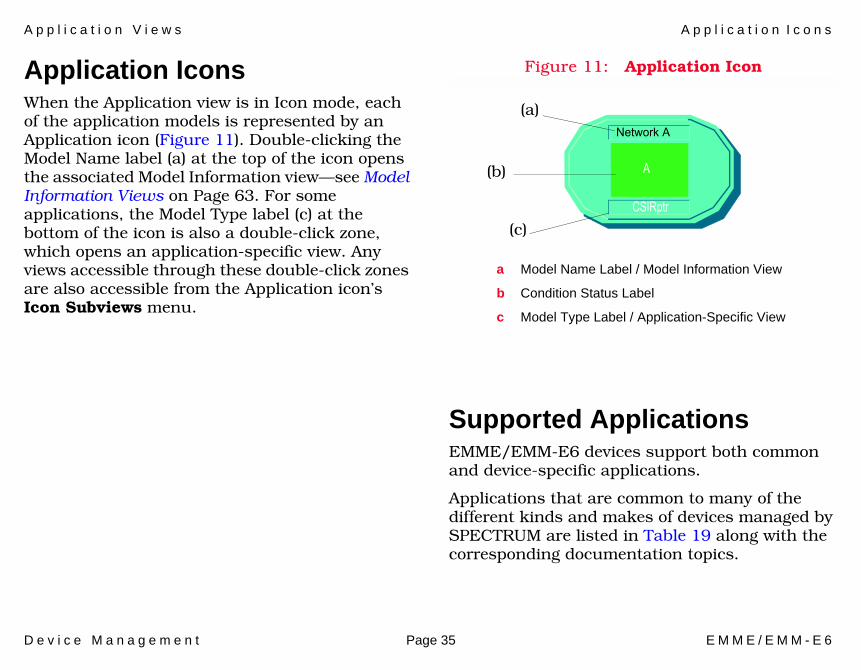
Application IconsWhen the Application view is in Icon mode, each of the application models is represented by an Application icon (Figure 11). Double-clicking the Model Name label (a) at the top of the icon opens the associated Model Information view—see Model Information Views on Page 63. For some applications, the Model Type label (c) at the bottom of the icon is also a double-click zone, which opens an application-specific view. Any views accessible through these double-click zones are also accessible from the Application icon’s Icon Subviews menu.
Figure 11: Application Icon
Supported ApplicationsEMME/EMM-E6 devices support both common and device-specific applications.
Applications that are common to many of the different kinds and makes of devices managed by SPECTRUM are listed in Table 19 along with the corresponding documentation topics.
a Model Name Label / Model Information View
b Condition Status Label
c Model Type Label / Application-Specific View
(a)
(b)
(c)
Network A
CSIRptr
A
A p p l i c a t i o n V i e w s N e t w o r k ( A , B , o r C ) A p p l i c a t i o n V i e w
D e v i c e M a n a g e m e n t Page 36 E M M E / E M M - E 6
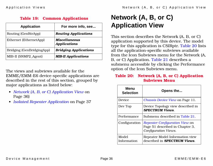
The views and subviews available for the EMME/EMM-E6 device-specific applications are described in the rest of this section, grouped by major applications as listed below:
• Network (A, B, or C) Application View on Page 36)
• Isolated Repeater Application on Page 37
Network (A, B, or C) Application View
This section describes the Network (A, B, or C) application supported by this device. The model type for this application is CSIRptr. Table 20 lists all the application-specific subviews available from the Icon Subviews menu for the Network (A, B, or C) Application. Table 21 describes a submenu accessible by clicking the Performance option of the Icon Subviews menu.
Table 19: Common Applications
Application For more info, see...
Routing (GenRtrApp) Routing Applications
Ethernet (EthernetApp) Miscellaneous Applications
Bridging (GenBridgingApp) Bridging Applications
MIB-II (SNMP2_Agent) MIB-II Applications
Table 20: Network (A, B, or C) Application Subviews Menu
Menu Selection Opens the...
Device Chassis Device View on Page 11.
Dev Top Device Topology view described in SPECTRUM Views.
Performance Submenu described in Table 21.
Configuration Repeater Configuration View on Page 51 described in Chapter 3, Configuration Views.
Model Information
Repeater Model Information view described in SPECTRUM Views.

A p p l i c a t i o n V i e w s I s o l a t e d R e p e a t e r A p p l i c a t i o n
D e v i c e M a n a g e m e n t Page 37 E M M E / E M M - E 6
Isolated Repeater ApplicationThis section describes the Isolated Repeater application supported by this device. The model type for this application is CSIIsolRptr. Table 22 lists all the application-specific subviews available from the Icon subviews menu for the Isolated Repeater application.
.\
Creating an Isolated RepeaterTo reconfigure a selected repeater to a stand alone mode (isolated), follow these steps:
1 Within the Chassis Device view, select a desired Repeater MIM icon (network B or C only).
2 From the Icon Subviews menu, select: For TPXMIM - Change Module Channel
Table 21: Network (A, B, or C) Application Subviews Menu (Performance Option)
Menu Selection Opens the...
Performance Performance view described in SPECTRUM Views.
Frame & Error Breakdown
Repeater Frame & Error Breakdown View on Page 17.
Frame Size & Protocols
Repeater Frame Size & Protocols View on Page 18.
Table 22: Isolated Repeater Application Subviews Menu
Menu Selection Opens the...
Device Chassis Device View on Page 11.
DevTop Device Topology view described SPECTRUM Views.
Configuration CSI Isolated Repeater Configuration View on Page 54.
Model Information
CSI Repeater Model Information view described in SPECTRUM Views.
A p p l i c a t i o n V i e w s A T M C l i e n t A p p l i c a t i o n
D e v i c e M a n a g e m e n t Page 38 E M M E / E M M - E 6
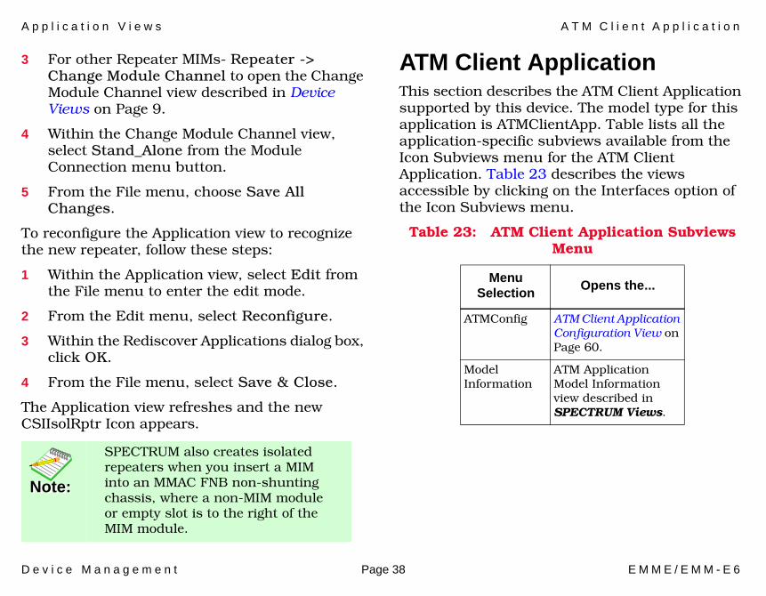
3 For other Repeater MIMs- Repeater -> Change Module Channel to open the Change Module Channel view described in Device Views on Page 9.
4 Within the Change Module Channel view, select Stand_Alone from the Module Connection menu button.
5 From the File menu, choose Save All Changes.
To reconfigure the Application view to recognize the new repeater, follow these steps:
1 Within the Application view, select Edit from the File menu to enter the edit mode.
2 From the Edit menu, select Reconfigure.
3 Within the Rediscover Applications dialog box, click OK.
4 From the File menu, select Save & Close.
The Application view refreshes and the new CSIIsolRptr Icon appears.
ATM Client ApplicationThis section describes the ATM Client Application supported by this device. The model type for this application is ATMClientApp. Table lists all the application-specific subviews available from the Icon Subviews menu for the ATM Client Application. Table 23 describes the views accessible by clicking on the Interfaces option of the Icon Subviews menu.
Note:Note:
SPECTRUM also creates isolated repeaters when you insert a MIM into an MMAC FNB non-shunting chassis, where a non-MIM module or empty slot is to the right of the MIM module.
Table 23: ATM Client Application Subviews Menu
Menu Selection Opens the...
ATMConfig ATM Client Application Configuration View on Page 60.
Model Information
ATM Application Model Information view described in SPECTRUM Views.
A p p l i c a t i o n V i e w s A T M C l i e n t A p p l i c a t i o n
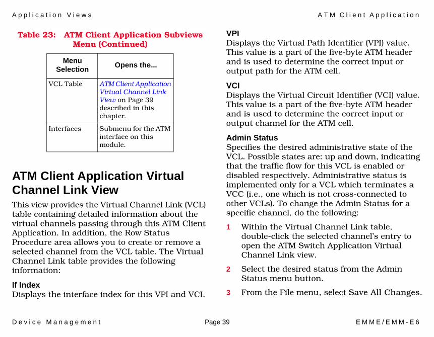
D e v i c e M a n a g e m e n t Page 39 E M M E / E M M - E 6
ATM Client Application Virtual Channel Link ViewThis view provides the Virtual Channel Link (VCL) table containing detailed information about the virtual channels passing through this ATM Client Application. In addition, the Row Status Procedure area allows you to create or remove a selected channel from the VCL table. The Virtual Channel Link table provides the following information:
If IndexDisplays the interface index for this VPI and VCI.
VPI Displays the Virtual Path Identifier (VPI) value. This value is a part of the five-byte ATM header and is used to determine the correct input or output path for the ATM cell.
VCIDisplays the Virtual Circuit Identifier (VCI) value. This value is a part of the five-byte ATM header and is used to determine the correct input or output channel for the ATM cell.
Admin StatusSpecifies the desired administrative state of the VCL. Possible states are: up and down, indicating that the traffic flow for this VCL is enabled or disabled respectively. Administrative status is implemented only for a VCL which terminates a VCC (i.e., one which is not cross-connected to other VCLs). To change the Admin Status for a specific channel, do the following:
1 Within the Virtual Channel Link table, double-click the selected channel’s entry to open the ATM Switch Application Virtual Channel Link view.
2 Select the desired status from the Admin Status menu button.
3 From the File menu, select Save All Changes.
VCL Table ATM Client Application Virtual Channel Link View on Page 39 described in this chapter.
Interfaces Submenu for the ATM interface on this module.
Table 23: ATM Client Application Subviews Menu (Continued)
Menu Selection Opens the...
A p p l i c a t i o n V i e w s A T M C l i e n t A p p l i c a t i o n
D e v i c e M a n a g e m e n t Page 40 E M M E / E M M - E 6
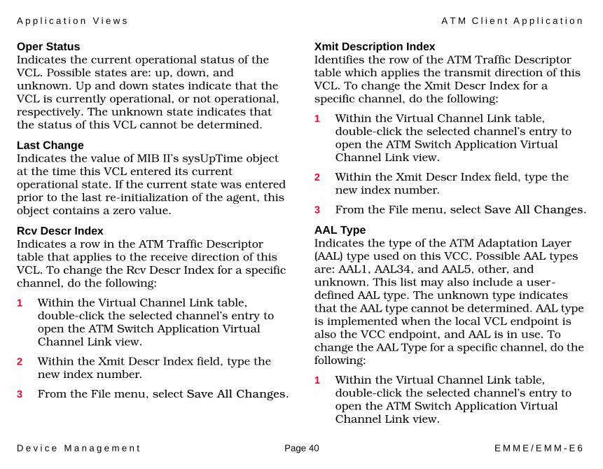
Oper StatusIndicates the current operational status of the VCL. Possible states are: up, down, and unknown. Up and down states indicate that the VCL is currently operational, or not operational, respectively. The unknown state indicates that the status of this VCL cannot be determined.
Last ChangeIndicates the value of MIB II’s sysUpTime object at the time this VCL entered its current operational state. If the current state was entered prior to the last re-initialization of the agent, this object contains a zero value.
Rcv Descr IndexIndicates a row in the ATM Traffic Descriptor table that applies to the receive direction of this VCL. To change the Rcv Descr Index for a specific channel, do the following:
1 Within the Virtual Channel Link table, double-click the selected channel’s entry to open the ATM Switch Application Virtual Channel Link view.
2 Within the Xmit Descr Index field, type the new index number.
3 From the File menu, select Save All Changes.
Xmit Description IndexIdentifies the row of the ATM Traffic Descriptor table which applies the transmit direction of this VCL. To change the Xmit Descr Index for a specific channel, do the following:
1 Within the Virtual Channel Link table, double-click the selected channel’s entry to open the ATM Switch Application Virtual Channel Link view.
2 Within the Xmit Descr Index field, type the new index number.
3 From the File menu, select Save All Changes.
AAL TypeIndicates the type of the ATM Adaptation Layer (AAL) type used on this VCC. Possible AAL types are: AAL1, AAL34, and AAL5, other, and unknown. This list may also include a user-defined AAL type. The unknown type indicates that the AAL type cannot be determined. AAL type is implemented when the local VCL endpoint is also the VCC endpoint, and AAL is in use. To change the AAL Type for a specific channel, do the following:
1 Within the Virtual Channel Link table, double-click the selected channel’s entry to open the ATM Switch Application Virtual Channel Link view.
A p p l i c a t i o n V i e w s A T M C l i e n t A p p l i c a t i o n
D e v i c e M a n a g e m e n t Page 41 E M M E / E M M - E 6
2 Select the desired type from the AAL Type menu button.
3 From the File menu, select Save All Changes.
Transmit SizeDisplays the maximum AAL5 CPCS SDU size in octets that is supported on the transmit direction of this VCC. Transmit Size is implemented when the local VCL endpoint is also the VCC endpoint, and AAL5 is in use. The Transmit Size can be altered. The maximum allowable value is 155 Mbs displayed in octets. To change the Transmit Size for a specific channel, do the following:
1 Within the Virtual Channel Link table, double-click the selected channel’s entry to open the ATM Switch Application Virtual Channel Link view.
2 Within the Transmit Size field, type the new Transmit Size number.
3 From the File menu, select Save All Changes.
Receive SizeDisplays the maximum AAL5 CPCS SDU size in octets that is supported on the receive direction of this VCC. Receive Size is implemented when the local VCL endpoint is also the VCC endpoint, and AAL5 is in use. The Receive Size can be altered. The maximum allowable value is 155 Mbs
displayed in octets. To change the Receive Size for a specific channel, do the following:
1 Within the Virtual Channel Link table, double-click the selected channel’s entry to open the ATM Switch Application Virtual Channel Link view.
2 Within the Receive Size field, type the new Receive Size number.
3 From the File menu, select Save All Changes.
Encaps TypeDisplays the type of data encapsulation used over the AAL5 SSCS layer. Possible Encaps types are: Routed, Bridged_8023, Bridged_8025, Bridged_8026, LAN_emulation_8023, LAN_emulation_8025, LLC_Encapsulation, Frame_Relay_Sscs, other, and unknown. Encaps type is implemented when the local VCL endpoint is also the VCC endpoint, and AAL5 is in use. To change the Encaps Type for a specific channel, do the following:
1 Within the Virtual Channel Link table, double-click the selected channel’s entry to open the ATM Switch Application Virtual Channel Link view.
2 Select the desired type from the Encaps Type menu button.
A p p l i c a t i o n V i e w s A T M C l i e n t A p p l i c a t i o n
D e v i c e M a n a g e m e n t Page 42 E M M E / E M M - E 6
3 From the File menu, select Save All Changes.
Cross Connect IdDisplays an Id for all associated VCLs and their cross-connections that are identified by entries in the Cross Connect table. The Cross Connect Id is initialized by the agent after the associated entries in the Cross Connect Table have been created. The Cross Connect Id is implemented only for a VCL which is cross-connected to other VCLs that belong to the same VCC.
Row StatusDisplays the row status used while creating, deleting or modifying a row in this table. Possible menu selections are: active, not_in _service, not_ready, create_and_go, create_and_wait, and destroy. To change the Row Status for a specific channel, do the following:
1 Within the Virtual Channel Link table, double-click the selected channel’s entry to open the ATM Switch Application Virtual Channel Link view.
2 Select the desired status from the Row Status menu button.
3 From the File menu, select Save All Changes.
The Row Status Procedure area of the ATM Client Application Virtual Channel Link view provides the following information and fields that allow you
to create or remove a virtual channel link from the Virtual Channel Link table.
Channel InformationAllows you to type If Index number, VPI number, and the VCU number for the channel you wish to create or remove.
Allows you to add a new virtual channel to the Virtual Channel Link table.
Allows you to remove an existing virtual channel from the Virtual Channel Link table.
To create or remove a virtual channels from the Virtual Channel Link table, follow these steps:
1 Set channel information by typing the If Index number, the VPI number, and the VCI number of the channel you want to add or remove in the Channel Information field. The numbers should be separated by periods.
2 Perform the view update by pressing enter or ctrl+s.
3 Select Create Channel or Remove Channel.
Create Channel
Remove Channel
A p p l i c a t i o n V i e w s F D D I S M T A p p l i c a t i o n
D e v i c e M a n a g e m e n t Page 43 E M M E / E M M - E 6
4 Within the Virtual Channel Link table, select Update.
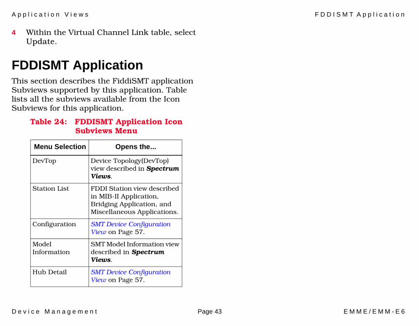
FDDISMT ApplicationThis section describes the FiddiSMT application Subviews supported by this application. Table lists all the subviews available from the Icon Subviews for this application.
Table 24: FDDISMT Application Icon Subviews Menu
Menu Selection Opens the...
DevTop Device Topology(DevTop) view described in Spectrum Views.
Station List FDDI Station view described in MIB-II Application, Bridging Application, and Miscellaneous Applications.
Configuration SMT Device Configuration View on Page 57.
Model Information
SMT Model Information view described in Spectrum Views.
Hub Detail SMT Device Configuration View on Page 57.

D e v i c e M a n a g e m e n t Page 44 E M M E / E M M - E 6
Performance Views
This section provides brief descriptions of the Performance views available for models of EMME/EMM-E6 devices in SPECTRUM.
Performance views provide statistical information about the operation of the device and packet information for the device and its ports. The following performance view is described in this section:
• Performance Views (Page 44)For more information on Performance views, refer to the SPECTRUM Views documentation.
Device Performance ViewAccess: From the Icon Subviews menu for the EMME/E6 Device icon, select Performance.
This view provides the following performance statistics about the packets being passed through the device:
• Received Rate• % Filtered• % Forwarded• Transmitted Rate
Figure 12: Device Performance View
Log
100.0
10.00
1.00
0.10
0.01
000:40:0 0:30:0 0:20:0
Value Average Peak Value
%Filtered
%Forwarded
Graph Properties Scroll to Date-Time
SpectroGRAPH: Bridging
Primary Application
System Up TimeManufacturer
Device Type
Serial Number
Network Address
%Received Rate
NameContactDescriptionLocation
File View Help
Primary Address
Tools Bookmarks
Bridging of type CSIBridge of Landscape IP_Address:Primary

D e v i c e M a n a g e m e n t Page 45 E M M E / E M M - E 6
Configuration Views
This section describes the various Configuration views and subviews available for models of EMME/EMM-6E Server devices in SPECTRUM.
Configuration views allow you to view and modify current settings for the modeled device and its interfaces, ports, and applications. The following Configuration views are available for models of EMME/EMM-6E devices:
• Device Configuration View on Page 45• Module and Port Configuration Views on
Page 47• Chassis Configuration View (EMME only)
(Page 46)• Repeater Configuration View (Page 51)• CSI Isolated Repeater Configuration View
(Page 54)• Interface Configuration Views (EMM-E6 only)
(Page 55)• Port Configuration View (for FDDI) (Page 56)• SMT Device Configuration View (Page 57)
• ATM Client Application Configuration View (Page 60)
Device Configuration ViewAccess: From the Icon Subviews menu for the Device icon, select Configuration.
This view (Figure 13) provides status and configuration information about the device as a whole as well as on a port-by-port basis. It also provides button access to an Interface Address Translation table and a subview that lets you establish redundancy for the model. Fields and column headings within the Device Configuration view and its subviews are explained in detail in the SPECTRUM Views documentation.
C o n f i g u r a t i o n V i e w s C h a s s i s C o n f i g u r a t i o n V i e w ( E M M E o n l y )
D e v i c e M a n a g e m e n t Page 46 E M M E / E M M - E 6
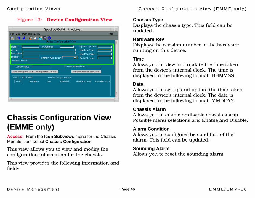
Figure 13: Device Configuration View
Chassis Configuration View (EMME only)Access: From the Icon Subviews menu for the Chassis Module icon, select Chassis Configuration.
This view allows you to view and modify the configuration information for the chassis.
This view provides the following information and fields:
Chassis TypeDisplays the chassis type. This field can be updated.
Hardware RevDisplays the revision number of the hardware running on this device.
TimeAllows you to view and update the time taken from the device’s internal clock. The time is displayed in the following format: HHMMSS.
DateAllows you to set up and update the time taken from the device’s internal clock. The date is displayed in the following format: MMDDYY.
Chassis AlarmAllows you to enable or disable chassis alarm. Possible menu selections are: Enable and Disable.
Alarm ConditionAllows you to configure the condition of the alarm. This field can be updated.
Sounding AlarmAllows you to reset the sounding alarm.
Primary Application
System Up TimeInterface Type
Interface Index
Serial Number
IP AddressModel ContactDescriptionLocation
File View Help
Contact Status
Primary Address
Number of Interfaces
Device Configuration View
Interface Configuration TableSort Find Update
Redundancy and Model Reconfiguration Options Interface Address Translation
Index Description Type Bandwidth Physical Address Operation Status
Tools Bookmarks
SpectroGRAPH: IP_Address
C o n f i g u r a t i o n V i e w s M o d u l e a n d P o r t C o n f i g u r a t i o n V i e w s
D e v i c e M a n a g e m e n t Page 47 E M M E / E M M - E 6
Module and Port Configuration ViewsAccess: From the Icon Subviews menu for the Chassis Module Icon, select Module Configuration or Port Configuration.
Both Module Configuration view and Port Configuration view provide information on the configuration and operating status of other modules (in addition to EMME/EMM-E6) installed in the MMAC FNB chassis and on selected individual ports on those modules.
The Configuration views are divided into four sections:
• Module Management / Port Management• Trap configuration• Alarm Configuration• Error Source
Module Management and Port Management are the only sections that include fields exclusive to the Module Configuration view and the Port Configuration view, therefore they are described separately.
Module Management (Module Configuration View Only)This area of the Module Configuration view provides the following information for the selected module:
Port CountDisplays the total number of ports on this module.
Ports OnDisplays the total number of ports currently in the ON state on this module.
Ports OperationalDisplays the number of operational ports on this module.
Module PortsAllows you to enable or disable all the ports on this module. Possible states are: Enable and Disable. You can also enable or disable individual ports by selecting Enable/Disable Port from the port’s Icon Subviews menu.
Port Management (Port Configuration View Only)This area of the Port Configuration view provides the following information for the selected port:
C o n f i g u r a t i o n V i e w s M o d u l e a n d P o r t C o n f i g u r a t i o n V i e w s
D e v i c e M a n a g e m e n t Page 48 E M M E / E M M - E 6
Port IDDisplays the number of the port identifying its location within the module.
Administrative StatusThis menu button allows you to select the desired operational state of the port. Possible selections are: Enable and Disable.
Operational StatusDisplays the current operational state of the port. Possible states are: Not-Operational and Operational.
Segmentation StatusDisplays the current segmentation state of the port. Possible states are: Not-Segmented and Segmented.
Link StatusDisplays the current link state of the port. Possible states are: Not-Linked, Linked, and Not-Applicable.
Topological StateDisplays the current port topological state. Possible states are: Station and Trunk.
Set Topological StateThis menu button allows you to select the desired topological state for the port. Possible selections are: Not_Forced or Forced_Trunk.
Trap ConfigurationThis area of the Module or Port Configuration view allows you to enable or disable any of the following types of traps:
Link TrapsThis menu button, when enabled, allows all packets indicating a change in link status to be reported within the trap database. Possible menu selections are: Disable, Enable, and other.
Segmentation TrapsThis menu button, when enabled, allows all packets indicating a change in segmentation status to be reported within the trap database. Possible menu selections are: Disable, Enable, and other.
Source Address TrapsThis button, when enabled, allows all packets indicating a change in source address to be reported within the trap database. Possible menu selections are: Disable, Enable, and other.
Alarm ConfigurationThis area of the Module or Port Configuration view provides configuration and status information for generation of alarms by the selected module. The Alarm Configuration section provides the following information:
C o n f i g u r a t i o n V i e w s M o d u l e a n d P o r t C o n f i g u r a t i o n V i e w s
D e v i c e M a n a g e m e n t Page 49 E M M E / E M M - E 6
Timebase (Port Configuration view only)Displays the time interval within which the specified number of errors needs to occur before the alarm is generated. This number can only be altered in the Repeater Configuration view described later in this chapter.
Traffic AlarmsThis menu button allows you to enable or disable detection of Traffic Alarms. Possible menu selections are: Disable and Enable.
Traffic ThresholdDisplays the threshold value within the alarm timebase which, once that number of packets is exceeded, generates a traffic alarm. You can alter this name. Allowable values are 1 to ~4 billion.
Traffic Alarm ConditionThis menu button allows you to disable the module or port if the traffic alarm threshold is exceeded and an alarm for the module is generated. This feature allows you to prevent excessive network traffic generated by alarm messages that are transmitted by the module. It also aids in module troubleshooting. Possible menu selections are: Don’t_Disable_Port and Disable_Port.
Collision AlarmsThis menu button allows you to Enable or Disable detection of Collision Alarms. Possible menu selections are: Disable and Enable.
Collision ThresholdDisplays the threshold value within the alarm timebase which, once that number of collisions per good packet is exceeded, generates a collision alarm. You can alter this number. Allowable values are: 1 to 15 collisions per good packet.
Collision Alarm ConditionThis menu button allows you to disable the module or port if the collision alarm threshold is exceeded and an alarm for the module is generated. This feature allows you to prevent excessive network traffic generated by alarm messages that are transmitted by the module. It also aids in module troubleshooting. Possible menu selections are: Don’t_Disable_Port and Dissable_Port.
Broadcast AlarmsThis menu button allows you to Enable or Disable detection of Broadcast Alarms. Possible menu selections are: Disable and Enable.
Broadcast ThresholdDisplays the threshold value within the alarm timebase which, once that number of broadcasts
C o n f i g u r a t i o n V i e w s M o d u l e a n d P o r t C o n f i g u r a t i o n V i e w s
D e v i c e M a n a g e m e n t Page 50 E M M E / E M M - E 6
received is exceeded, generates a broadcast alarm. Allowable values are 1 to ~4 billion.
Broadcast Alarm ConditionAllows you to disable the module or port if the broadcast alarm threshold is exceeded and an alarm for the module is generated. This feature allows you to prevent excessive network traffic generated by alarm messages that are transmitted by the module. It also aids in module troubleshooting. Possible menu selections are: Don’t_Disable_Port and Dissable_Port.
Error AlarmsAllows you to Enable or Disable detection of Error Alarms. Possible menu selections are: Disable and Enable.
Error ThresholdDisplays the threshold value within the alarm timebase which, once the percentage of errors per alarms is reported.
Error Alarm ConditionAllows you to disable the module or port if the error alarm threshold is exceeded and an alarm for the module is generated. This feature allows you to prevent excessive network traffic generated by alarm messages that are transmitted by the module. It also aids in module troubleshooting.
Possible menu selections are: Don’t_Disable_Port and Dissable_Port.
Error SourceThis area of the Module or Port Configuration view provides a series of buttons allowing you to select error types to include in the error sum. The selectable error types are as follows:
CRCDescribes the number of packets received by the module with bad Cyclical Redundancy Checks (CRCs).
RuntsDescribes the number of runt packets received by the module. A runt packet is one byte less than the standard Ethernet frame of 64 bytes (not including preamble).
OOW_CollsDescribes the number of collisions out of the standard window (51.2µs) due to a network problem.
Describes the number of misaligned packets detected by the module.
C o n f i g u r a t i o n V i e w s R e p e a t e r C o n f i g u r a t i o n V i e w
D e v i c e M a n a g e m e n t Page 51 E M M E / E M M - E 6
No_ResourceDescribes the number of times the module ran out of resources (i.e., lack of buffer space) and could not accept packets.
GiantsDescribes the number of giant packets received by the module. A giant packet exceeds 1518 bytes (not including preamble).
Repeater Configuration ViewAccess: From the Icon Subviews menu for the Repeater Port label, select Repeater Configuration.
The Repeater Configuration view provides information on the configuration and operating status of the repeater.
Repeater ManagementThis area of the Repeater Configuration view provides the following port information:
Port CountDisplays the total number of ports on this LAN segment.
Ports OnDisplays the total number of ports currently in the ON state on this network.
Ports OperationalDisplays the number of operational ports on this network.
Network PortsThis menu button allows you to enable the network ports on this network segment. Possible states are: NoEnable and Enable.
Network Port SecurityThis menu button allows you to lock or unlock repeater ports. Possible states are: Locked and Unlocked.
Source Address ManagementThis section of the Repeater Configuration view allows you to configure the Aging time.
Aging IntervalDisplays the minimum time, in seconds, that an inactive source address will remain in the database before being selected for removal. The source address timer runs continuously beginning at the time the device is turned on; source addresses that are added to the database during one timer cycle will remain in the database for the rest of the current cycle and at least through the next complete cycle. If no packets have been received from that address during one complete cycle, the address will be removed.
C o n f i g u r a t i o n V i e w s
D e v i c e M a n a g e m e n t Page 52 E M M E / E M M - E 6
Aging Interval is user-configurable. Allowable range is 0 to 4320 (three days).
Trap ConfigurationThis area of the Repeater Configuration view allows you to enable or disable any of the following types of traps:
Link TrapsThis menu button, when enabled, allows all packets indicating a change in link status to be reported within the trap database. Possible menu selections are: Disable, Enable, and other.
Segmentation TrapsThis menu button, when enabled, allows all packets indicating a change in segmentation status to be reported within the trap database. Possible menu selections are: Disable, Enable, and other.
Source Address TrapsThis menu button, when enabled, allows all packets indicating a change in source address to be reported within the trap database. Possible menu selections are: Disable, Enable, and other.
Alarm ConfigurationThis area of the Repeater Configuration view provides configuration information on generating alarms for the selected module. This section contains the following fields:
TimebaseDisplays the time interval, in seconds, within which the specified number of errors needs to occur before the alarm is generated. This time interval is user-configurable. The lowest allowable value is 10.
Traffic AlarmsThis menu button allows you to enable or disable detection of Traffic Alarms. Possible menu selections are: Enable and Disable.
Traffic ThresholdDisplays the threshold value within the alarm timebase which, once that number of packets is exceeded, generates a traffic alarm. This field is user-configurable. The allowable range is 1 to ~4 billion.
Collision AlarmsThis menu button allows you to enable or disable detection of Collision Alarms. Possible menu selections are: Enable and Disable.

C o n f i g u r a t i o n V i e w s
D e v i c e M a n a g e m e n t Page 53 E M M E / E M M - E 6
Collision ThresholdDisplays the threshold value within the alarm timebase which, once that number of collisions per good packet is exceeded, generates a collision alarm. This value is user-configurable. Allowable range is 1 to 15 collisions per good packet.
Broadcast AlarmsThis menu button allows you to Enable or Disable detection of Broadcast Alarms.
Broadcast ThresholdDisplays the threshold value within the alarm timebase which, once that number of broadcasts received is exceeded, generates a broadcast alarm. This value is user-configurable. Allowable range is 1 to ~4 billion.
Error AlarmsThis menu button allows you to enable or disable detection of Error Alarms. Possible menu selections are: Enable and Disable.
Error ThresholdDisplays the threshold value within the alarm timebase which, once the percentage of errors per good packet is exceeded, generates an error alarm. This value is user-configurable. Allowable range is 1 to 100.
Error SourceThis area of the Repeater Configuration view provides a series of buttons allowing you to select the types of errors to include in the error sum. The selectable error types are as follows:
CRCDescribes the number of packets received by the module with bad CRC (Cyclical Redundancy Checks).
RuntsDescribes the number of runt packets received by the module. A runt packet is one byte less than the standard Ethernet frame of 64 bytes (not including preamble).
OOW_CollsDescribes the number of collisions out of the standard window (51.2 µs) due to a network problem.
AlignmentDescribes the number of misaligned packets detected by the module.
No_ResourceDescribes the number of times the module ran out of resources (i.e., lack of buffer space) and could not accept packets.

C o n f i g u r a t i o n V i e w s C S I I s o l a t e d R e p e a t e r C o n f i g u r a t i o n V i e w
D e v i c e M a n a g e m e n t Page 54 E M M E / E M M - E 6
GiantsDescribes the number of giant packets received by the module. A giant packet exceeds 1518 bytes (not including preamble).
Board MapThis area of the Repeater Configuration view provides a series of read-only indicator buttons displaying which slots in the MMAC FNB chassis this repeater resides in.
ManagesThis area of the Repeater Configuration view displays the model name of the device managing this repeater. This section also allows you to access the Device Configuration view by double-clicking on the model name of the managing device, or highlighting it and clicking OK.
CSI Isolated Repeater Configuration ViewAccess: From the Icon Subviews menu for the CSIIsoRptr icon, select Configuration.
This view provides information on the configuration and operating status of the network segment that the isolated repeater is monitoring.
In addition to the Model Name and the Network Address, the CSI Isolated Repeater Configuration view provides the following information:
Repeater ManagementThis section of the CSI Isolated Repeater Configuration view displays the Port Group Management table, which provides the following information:
Mgmt. NameDisplays the slot number where this repeater is located in the chassis.
Group IDIdentifies a repeater in a system where a single agent manages multiple repeaters.
Port CountDisplays the total number of ports on this LAN segment.
Ports EnabDisplays the number of ports enabled.
Ports OnDisplays the total number of ports in the ON state on this network.
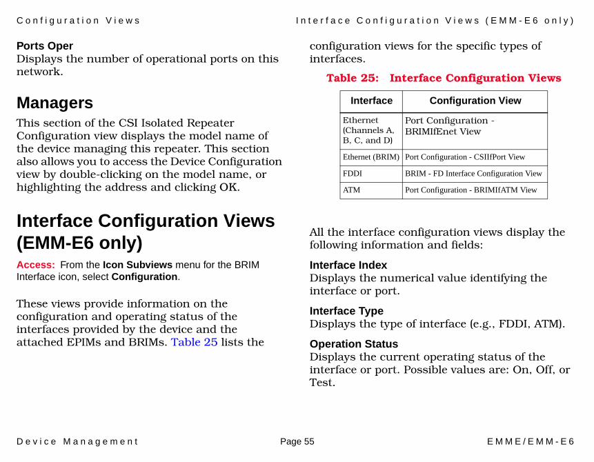
C o n f i g u r a t i o n V i e w s I n t e r f a c e C o n f i g u r a t i o n V i e w s ( E M M - E 6 o n l y )
D e v i c e M a n a g e m e n t Page 55 E M M E / E M M - E 6
Ports OperDisplays the number of operational ports on this network.
ManagersThis section of the CSI Isolated Repeater Configuration view displays the model name of the device managing this repeater. This section also allows you to access the Device Configuration view by double-clicking on the model name, or highlighting the address and clicking OK.
Interface Configuration Views (EMM-E6 only)Access: From the Icon Subviews menu for the BRIM Interface icon, select Configuration.
These views provide information on the configuration and operating status of the interfaces provided by the device and the attached EPIMs and BRIMs. Table 25 lists the
configuration views for the specific types of interfaces.
All the interface configuration views display the following information and fields:
Interface IndexDisplays the numerical value identifying the interface or port.
Interface TypeDisplays the type of interface (e.g., FDDI, ATM).
Operation StatusDisplays the current operating status of the interface or port. Possible values are: On, Off, or Test.
Table 25: Interface Configuration Views
Interface Configuration View
Ethernet (Channels A, B, C, and D)
Port Configuration - BRIMIfEnet View
Ethernet (BRIM) Port Configuration - CSIIfPort View
FDDI BRIM - FD Interface Configuration View
ATM Port Configuration - BRIMIfATM View
C o n f i g u r a t i o n V i e w s P o r t C o n f i g u r a t i o n V i e w ( f o r F D D I )
D e v i c e M a n a g e m e n t Page 56 E M M E / E M M - E 6
Admin StatusThis menu button allows you to enable or disable the current administrative state of the port. Possible values are: On (Enabled), Off (Disabled), or Test.
IF DescriptionProvides a description of the interface or port (e.g., Ctron FDDI Port Channel E).
Port Configuration View (for FDDI)Access: From the Icon Subviews menu for the FDDI Port Label, select Port Configuration View.
This view provides information concerning the configuration and management of the port located on the front panel of the FDDI BRIM. To access the Port Configuration view, do the following:
The Port Configuration view provides the following information concerning the port management:
Port ActionProvides a menu button that allows you to enable/disable the port. Possible menu selections are: Other, Enable_Port, and Disable_Port. The state returns to Other once the port is Enabled/Disabled.
Port State Displays the status of this port. Possible states are: Disabled, Connecting, Standby, or Active.
Port TypeDisplays the type of port. Possible port types are: A_Port or B_Port, Slave or Master.
Link Error Rate EstimateDisplays a cumulative long-term average of the bit error rate, which represents the quality of the physical link. The link error rate estimate is computed when the port is connected and every 10 seconds thereafter. It ranges from 10-4 to 10-15
and is reported as a whole integer. For example, if the port’s link error rate estimate is computed to be 10-5, the value reported in this field would be 5, which represents an actual rate of 1,250 bit errors per second. A lower link error rate estimate indicates a higher bit error rate, as shown in Figure 14.
Note:Note:
The FDDI Port Configuration view is only accessible for the EMM-E6 with a FDDI BRIM attached to it.
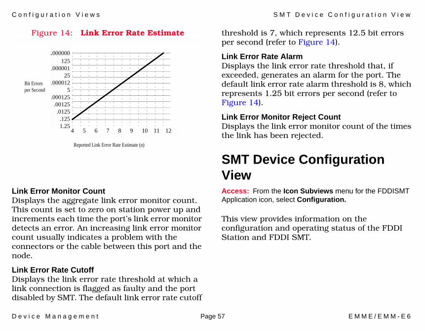
C o n f i g u r a t i o n V i e w s S M T D e v i c e C o n f i g u r a t i o n V i e w
D e v i c e M a n a g e m e n t Page 57 E M M E / E M M - E 6
Figure 14: Link Error Rate Estimate
Link Error Monitor CountDisplays the aggregate link error monitor count. This count is set to zero on station power up and increments each time the port’s link error monitor detects an error. An increasing link error monitor count usually indicates a problem with the connectors or the cable between this port and the node.
Link Error Rate CutoffDisplays the link error rate threshold at which a link connection is flagged as faulty and the port disabled by SMT. The default link error rate cutoff
threshold is 7, which represents 12.5 bit errors per second (refer to Figure 14).
Link Error Rate AlarmDisplays the link error rate threshold that, if exceeded, generates an alarm for the port. The default link error rate alarm threshold is 8, which represents 1.25 bit errors per second (refer to Figure 14).
Link Error Monitor Reject CountDisplays the link error monitor count of the times the link has been rejected.
SMT Device Configuration ViewAccess: From the Icon Subviews menu for the FDDISMT Application icon, select Configuration.
This view provides information on the configuration and operating status of the FDDI Station and FDDI SMT.
.000000125
.00000125
.0000125
.000125.00125.0125.1251.25
Bit Errorsper Second
Reported Link Error Rate Estimate (n)
4 5 6 7 8 9 10 11 12
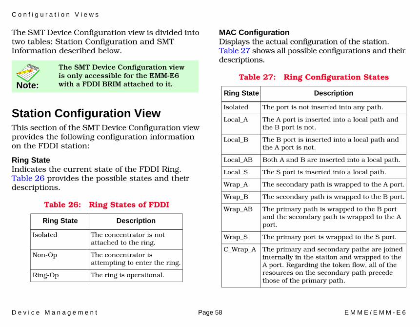
C o n f i g u r a t i o n V i e w s
D e v i c e M a n a g e m e n t Page 58 E M M E / E M M - E 6
The SMT Device Configuration view is divided into two tables: Station Configuration and SMT Information described below.
Station Configuration ViewThis section of the SMT Device Configuration view provides the following configuration information on the FDDI station:
Ring StateIndicates the current state of the FDDI Ring. Table 26 provides the possible states and their descriptions.
MAC ConfigurationDisplays the actual configuration of the station. Table 27 shows all possible configurations and their descriptions.
Note:Note:
The SMT Device Configuration view is only accessible for the EMM-E6 with a FDDI BRIM attached to it.
Table 26: Ring States of FDDI
Ring State Description
Isolated The concentrator is not attached to the ring.
Non-Op The concentrator is attempting to enter the ring.
Ring-Op The ring is operational.
Table 27: Ring Configuration States
Ring State Description
Isolated The port is not inserted into any path.
Local_A The A port is inserted into a local path and the B port is not.
Local_B The B port is inserted into a local path and the A port is not.
Local_AB Both A and B are inserted into a local path.
Local_S The S port is inserted into a local path.
Wrap_A The secondary path is wrapped to the A port.
Wrap_B The secondary path is wrapped to the B port.
Wrap_AB The primary path is wrapped to the B port and the secondary path is wrapped to the A port.
Wrap_S The primary port is wrapped to the S port.
C_Wrap_A The primary and secondary paths are joined internally in the station and wrapped to the A port. Regarding the token flow, all of the resources on the secondary path precede those of the primary path.
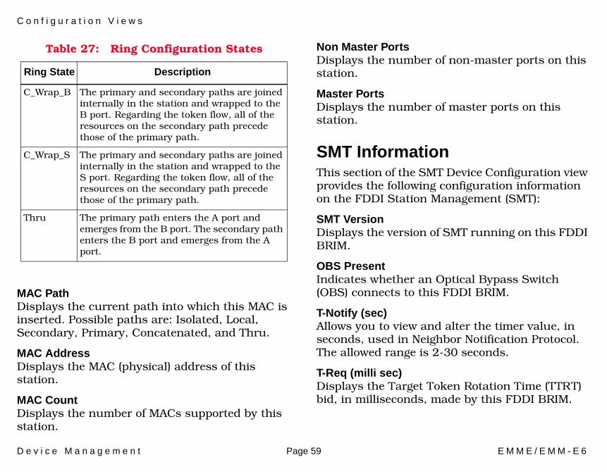
C o n f i g u r a t i o n V i e w s
D e v i c e M a n a g e m e n t Page 59 E M M E / E M M - E 6
MAC Path Displays the current path into which this MAC is inserted. Possible paths are: Isolated, Local, Secondary, Primary, Concatenated, and Thru.
MAC AddressDisplays the MAC (physical) address of this station.
MAC CountDisplays the number of MACs supported by this station.
Non Master PortsDisplays the number of non-master ports on this station.
Master PortsDisplays the number of master ports on this station.
SMT InformationThis section of the SMT Device Configuration view provides the following configuration information on the FDDI Station Management (SMT):
SMT VersionDisplays the version of SMT running on this FDDI BRIM.
OBS PresentIndicates whether an Optical Bypass Switch (OBS) connects to this FDDI BRIM.
T-Notify (sec)Allows you to view and alter the timer value, in seconds, used in Neighbor Notification Protocol. The allowed range is 2-30 seconds.
T-Req (milli sec)Displays the Target Token Rotation Time (TTRT) bid, in milliseconds, made by this FDDI BRIM.
C_Wrap_B The primary and secondary paths are joined internally in the station and wrapped to the B port. Regarding the token flow, all of the resources on the secondary path precede those of the primary path.
C_Wrap_S The primary and secondary paths are joined internally in the station and wrapped to the S port. Regarding the token flow, all of the resources on the secondary path precede those of the primary path.
Thru The primary path enters the A port and emerges from the B port. The secondary path enters the B port and emerges from the A port.
Table 27: Ring Configuration States
Ring State Description
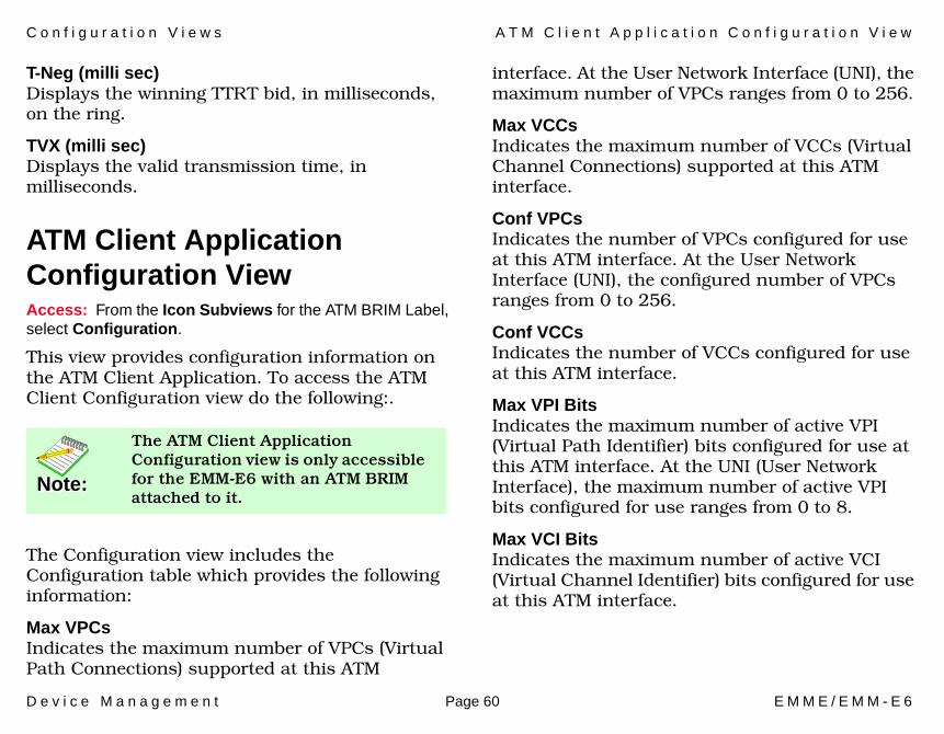
C o n f i g u r a t i o n V i e w s A T M C l i e n t A p p l i c a t i o n C o n f i g u r a t i o n V i e w
D e v i c e M a n a g e m e n t Page 60 E M M E / E M M - E 6
T-Neg (milli sec)Displays the winning TTRT bid, in milliseconds, on the ring.
TVX (milli sec)Displays the valid transmission time, in milliseconds.
ATM Client Application Configuration ViewAccess: From the Icon Subviews for the ATM BRIM Label, select Configuration.
This view provides configuration information on the ATM Client Application. To access the ATM Client Configuration view do the following:.
The Configuration view includes the Configuration table which provides the following information:
Max VPCs Indicates the maximum number of VPCs (Virtual Path Connections) supported at this ATM
interface. At the User Network Interface (UNI), the maximum number of VPCs ranges from 0 to 256.
Max VCCs Indicates the maximum number of VCCs (Virtual Channel Connections) supported at this ATM interface.
Conf VPCsIndicates the number of VPCs configured for use at this ATM interface. At the User Network Interface (UNI), the configured number of VPCs ranges from 0 to 256.
Conf VCCs Indicates the number of VCCs configured for use at this ATM interface.
Max VPI BitsIndicates the maximum number of active VPI (Virtual Path Identifier) bits configured for use at this ATM interface. At the UNI (User Network Interface), the maximum number of active VPI bits configured for use ranges from 0 to 8.
Max VCI BitsIndicates the maximum number of active VCI (Virtual Channel Identifier) bits configured for use at this ATM interface.
Note:Note:
The ATM Client Application Configuration view is only accessible for the EMM-E6 with an ATM BRIM attached to it.
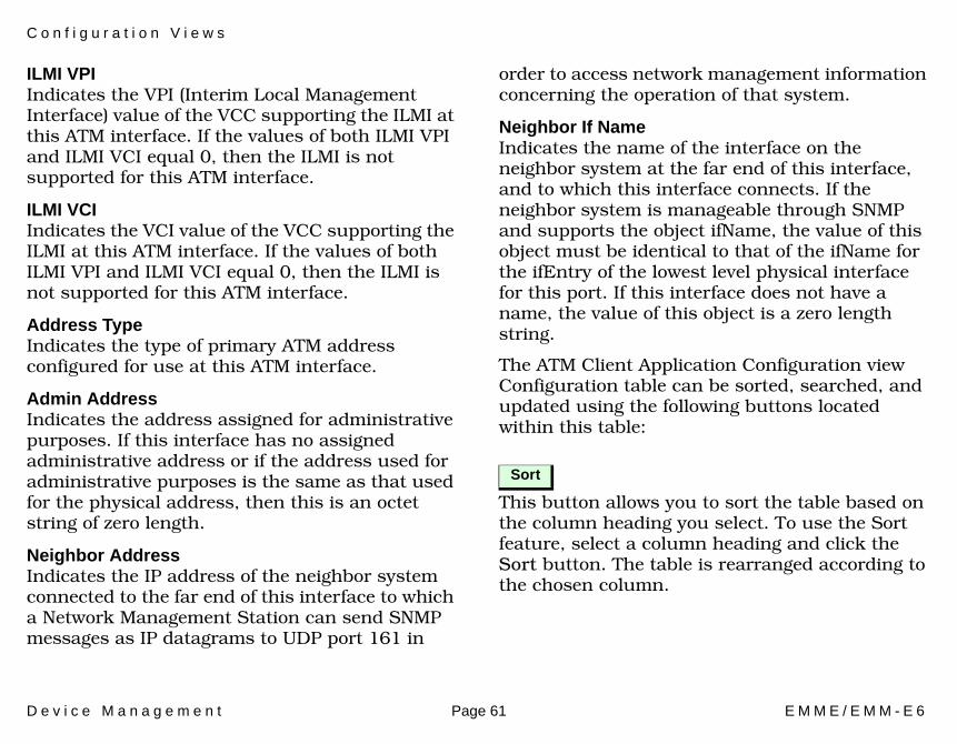
C o n f i g u r a t i o n V i e w s
D e v i c e M a n a g e m e n t Page 61 E M M E / E M M - E 6
ILMI VPI Indicates the VPI (Interim Local Management Interface) value of the VCC supporting the ILMI at this ATM interface. If the values of both ILMI VPI and ILMI VCI equal 0, then the ILMI is not supported for this ATM interface.
ILMI VCIIndicates the VCI value of the VCC supporting the ILMI at this ATM interface. If the values of both ILMI VPI and ILMI VCI equal 0, then the ILMI is not supported for this ATM interface.
Address TypeIndicates the type of primary ATM address configured for use at this ATM interface.
Admin AddressIndicates the address assigned for administrative purposes. If this interface has no assigned administrative address or if the address used for administrative purposes is the same as that used for the physical address, then this is an octet string of zero length.
Neighbor AddressIndicates the IP address of the neighbor system connected to the far end of this interface to which a Network Management Station can send SNMP messages as IP datagrams to UDP port 161 in
order to access network management information concerning the operation of that system.
Neighbor If NameIndicates the name of the interface on the neighbor system at the far end of this interface, and to which this interface connects. If the neighbor system is manageable through SNMP and supports the object ifName, the value of this object must be identical to that of the ifName for the ifEntry of the lowest level physical interface for this port. If this interface does not have a name, the value of this object is a zero length string.
The ATM Client Application Configuration view Configuration table can be sorted, searched, and updated using the following buttons located within this table:
This button allows you to sort the table based on the column heading you select. To use the Sort feature, select a column heading and click the Sort button. The table is rearranged according to the chosen column.
Sort
C o n f i g u r a t i o n V i e w s
D e v i c e M a n a g e m e n t Page 62 E M M E / E M M - E 6
To use the Find feature, select a column heading, click the Find button, and enter a search string in the dialog box.
This button allows you to update information.
Find
Update
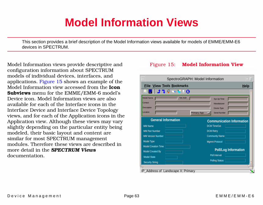
D e v i c e M a n a g e m e n t Page 63 E M M E / E M M - E 6
Model Information Views
This section provides a brief description of the Model Information views available for models of EMME/EMM-E6 devices in SPECTRUM.
Model Information views provide descriptive and configuration information about SPECTRUM models of individual devices, interfaces, and applications. Figure 15 shows an example of the Model Information view accessed from the Icon Subviews menu for the EMME/EMM-6 model’s Device icon. Model Information views are also available for each of the Interface icons in the Interface Device and Interface Device Topology views, and for each of the Application icons in the Application view. Although these views may vary slightly depending on the particular entity being modeled, their basic layout and content are similar for most SPECTRUM management modules. Therefore these views are described in more detail in the SPECTRUM Views documentation.
Figure 15: Model Information View
File View
SpectroGRAPH: Model Information
Model Name
Contact
Description
Location
Net Addr Sys Up Time
Manufacturer
Device Type
Serial Number
MM Version Number
MM Name
MM Part Number
General Information Communication Information
Community Name
DCM TimeOut
DCM Retry
Poll/Log InformationModel Created By
Model Type
Model Creation Time
Poll Interval
Polling StatusModel State
Security String
Mgmnt Protocol
HelpTools Bookmarks
IP_Address of Landscape X: Primary
Primary App
D e v i c e M a n a g e m e n t Page 64 E M M E / E M M - E 6
Index
AA_Port 56AAL Type 40Accum 17, 19Address
MAC 11Address Translation table 32Address Type 61Admin
Address 61Status 39, 56
AdministrativeStatus 48
Administrative Status 10, 31Aging Interval 51Alarm
Condition 46Configuration 48, 52
Alignment 50, 53Application
CommonBridging
(GenBridgingApp) 36Ethernet (EthernetApp) 36MIB-II (SNMP2_Agent) 36Routing (GenRtrApp) 36
Device-specific 36
Icons 34ATM
Client Application 38Configuration View 60
Label 21Switch Application Virtual
Channel Link View 39
BB_Port 56Board Map 54Bridge
Detail 14Model Information 14
BRIM- FD Interface Configuration
View 55Label 20Port 16
Status Label 22Type Label 22
BroadcastAlarm Condition 50Alarms 49, 53Threshold 53
BRtrCSIEMM_E6 6
CChange
Module Channel View 24Port Channel View 29
ChassisAlarm 46Type 46
Chassis Device View 9Collision Threshold 53Condition Status Label 35Conf VCCs 60Conf VPCs 60Configuration views 45CRC 50, 53Creating an Isolated Repeater 37Cross Connect Id 42CSI Isolated Repeater
Configuration 54Cyclical Redundancy Checks 50, 53
DDate 46Delta 17, 18Device Configuration View 45Device icon 6, 9, 34
I n d e x I n d e x
D e v i c e M a n a g e m e n t Page 65 E M M E / E M M - E 6
Device Performance View 44Devices supported by this module 6
EEMME/EMM-E6
Model Information 13Enable/Disable 29
Port 25Encaps Type 41Error
Alarms 50Breakdown 18Source 50, 53
FFDDI Label 20FddiSMT Application 43Find 62Frame
Size 19
GGiant Packets 51Giants 51, 54Group ID 54
HHardware
Rev 46HubCSIEMME 6HubCSIEMM-E6 6
IIcon mode 34Icons
Device 6, 34Interface 33
IFDescription 56Index 39
ILMIVCI 61VPI 61
InterfaceChannel 15Configuration
Views 55Device View 30Icon 10Index 55Number 10Status 15Type 55
Interface Device Topology View 33Interface Status View 31
Administrative Status 31Operational Status 31
Isolated Repeater Application 37Isolation Station 27
LLabels
Application IconCondition Status 35Model Name 35Model Type 35
Last Change 40Link
ErrorMonitor
Count 57Reject Count 57
RateAlarm 57Cutoff 57Estimate 56
Graph 57Status 48
List mode 34
MMAC
Address 11, 59
I n d e x I n d e x
D e v i c e M a n a g e m e n t Page 66 E M M E / E M M - E 6
Configuration 58Count 59Path 59
Manages 54, 55Master 56
Ports 59Max
VCCs 60VCI Bits 60VPCs 60VPI Bits 60
Mgmt. Name 54MIM
Icon 22Icon Subviews Menu 24Identification Labels 23
Misaligned Packets 50Mode (Icon or List) 34Model Information views 63Model type 6Model Type Label 35Module
Channel or Isolation Station 23Configuration View 47Connection 24DevTop View 24Management 47Notes 24Number 24Performance 24Ports 47Type 23
MotMPRouter 6
NNeighbor
Address 61If Name 61Notification Protocol 59
Network I/O ports 33Network Information 11No_Resource 51, 53Non Master Ports 59Non-Repeater MIM 23
OOBS Present 59OOW_Colls 53Oper Status 40Operation Status 55Operational Status 31
PPerformance View 44Performance views 44Physical Device View 30Port
Action 56
ConfigurationView 47View (for FDDI) 56
Count 47, 51, 54Frame
& Error Breakdown 25, 29Size & Protocols 25, 29
Management 47, 57Notes 25Number 25, 30Performance 25State 56Statistics 26Status 26, 30Type 10, 56
Port Configuration- BRIMIfATM View 55- BRIMIfEnet View 55- CSIIfPort View 55
Port Display Form 14Ports
Enab 54On 47, 51, 54Oper 55Operational 47, 51
Protocols 19
RRcv Descr Index 40Receive Size 41
I n d e x I n d e x
D e v i c e M a n a g e m e n t Page 67 E M M E / E M M - E 6
RepeaterAlarms 16Configuration View 51Management 54MIM 23Model Information 16Performance 16Port
Label 19, 25Required Reading 5Ring State 58Row Status 42Row Status Procedure Area 42Runt Packets 53Runts 53
SSecondary Address Panel 32Serial Number 24Serial ports 33Slave 56Slot Number 23SMT
Device Configuration View 57Information 59Version 59
Sort 61Sounding Alarm 46Source Address Management 51Spanning Tree
Information 14StandAlone 23, 27Static Database Table 14Station
Configuration View 58
TTarget Token Rotation Time 59Time 46Timebase 52T-Neg 60T-Notify 59Topology view 6Total 17, 18TPXMIM 26
Icon Subviews Menu 27Identification Labels 27Port Labels 28
TrafficAlarm Condition 49Alarms 49Threshold 49, 52
Transmit Size 41Transparent Bridge
Info 14Trap
Configuration 48, 52T-Req 59TTRT 60TVX 60
VValid Transmission Time 60VCI 39Views
Application 34Configuration 45Device Configuration 45Device Performance 44Interface Device 9Interface Status 31Model Information 63Performance 44Topology 6
VPI 39
XXmit
Description Index 40