spectrum mpls transport manager - ca...
TRANSCRIPT

User Guide (5120)
r9.1
SPECTRUM® MPLS Transport
Manager

This documentation and any related computer software help programs (hereinafter referred to as the
―Documentation‖) is for the end user’s informational purposes only and is subject to change or withdrawal by CA at
any time.
This Documentation may not be copied, transferred, reproduced, disclosed, modified or duplicated, in whole or in
part, without the prior written consent of CA. This Documentation is confidential and proprietary information of CA
and protected by the copyright laws of the United States and international treaties.
Notwithstanding the foregoing, licensed users may print a reasonable number of copies of the Documentation for
their own internal use, and may make one copy of the related software as reasonably required for back-up and
disaster recovery purposes, provided that all CA copyright notices and legends are affixed to each reproduced copy.
Only authorized employees, consultants, or agents of the user who are bound by the provisions of the license for
the Product are permitted to have access to such copies.
The right to print copies of the Documentation and to make a copy of the related software is limited to the period
during which the applicable license for the Product remains in full force and effect. Should the license terminate for
any reason, it shall be the user’s responsibility to certify in writing to CA that all copies and partial copies of the
Documentation have been returned to CA or destroyed.
EXCEPT AS OTHERWISE STATED IN THE APPLICABLE LICENSE AGREEMENT, TO THE EXTENT PERMITTED BY
APPLICABLE LAW, CA PROVIDES THIS DOCUMENTATION ―AS IS‖ WITHOUT WARRANTY OF ANY KIND, INCLUDING
WITHOUT LIMITATION, ANY IMPLIED WARRANTIES OF MERCHANTABILITY, FITNESS FOR A PARTICULAR PURPOSE
OR NONINFRINGEMENT. IN NO EVENT WILL CA BE LIABLE TO THE END USER OR ANY THIRD PARTY FOR ANY LOSS
OR DAMAGE, DIRECT OR INDIRECT, FROM THE USE OF THIS DOCUMENTATION, INCLUDING WITHOUT
LIMITATION, LOST PROFITS, BUSINESS INTERRUPTION, GOODWILL, OR LOST DATA, EVEN IF CA IS EXPRESSLY
ADVISED OF SUCH LOSS OR DAMAGE.
The use of any product referenced in the Documentation is governed by the end user’s applicable license
agreement.
The manufacturer of this Documentation is CA.
Provided with ―Restricted Rights.‖ Use, duplication or disclosure by the United States Government is subject to the
restrictions set forth in FAR Sections 12.212, 52.227-14, and 52.227-19(c)(1) - (2) and DFARS Section
252.227-7014(b)(3), as applicable, or their successors.
All trademarks, trade names, service marks, and logos referenced herein belong to their respective companies.
Copyright © 2009 CA. All rights reserved.
CA Product References
This document references the following CA products:
■ SPECTRUM® Network Fault Manager (SPECTRUM)
■ SPECTRUM® MPLS Transport Manager (MPLS Transport Manager)
Contact CA
Contact Technical Support
For your convenience, CA provides one site where you can access the
information you need for your Home Office, Small Business, and Enterprise CA
products. At http://ca.com/support, you can access the following:
■ Online and telephone contact information for technical assistance and
customer services
■ Information about user communities and forums
■ Product and documentation downloads
■ CA Support policies and guidelines
■ Other helpful resources appropriate for your product
Provide Feedback
If you have comments or questions about CA product documentation, you can
send a message to [email protected].
If you would like to provide feedback about CA product documentation,
complete our short customer survey, which is also available on the CA support
website, found at http://ca.com/support.

Contents 5
Contents
Chapter 1: MPLS Transport Manager 7
About MPLS Transport Manager ................................................................. 7
Who Should Use MPLS Transport Manager ....................................................... 7
How MPLS Transport Manager Works with MPLS-TE .............................................. 8
Devices Supported by MPLS Transport Manager .................................................. 9
System Requirements ......................................................................... 10
Chapter 2: Configuring MPLS Transport Manager 11
How to Install and Configure MPLS Transport Manager .......................................... 11
Preparing Existing Devices for MPLS Transport Manager ......................................... 12
Reconfigure All Devices .................................................................... 13
Reconfigure Selected Devices .............................................................. 13
Configure Port Polling on LSPs ................................................................. 14
Configure SpectroSERVER Processing of MPLS Traps ............................................ 15
Chapter 3: Managing Your LSP Data 17
Viewing LSP Details ........................................................................... 17
Open MPLS Transport Manager ............................................................. 18
Discover Your LSPs ........................................................................ 19
Main Window for MPLS .................................................................... 19
View LSP Paths ............................................................................... 22
Static vs. Dynamic Paths .................................................................. 22
Spotlighting LSP Paths .................................................................... 23
View Hops in an LSP Path ..................................................................... 23
Unmodeled Hops in MPLS Transport Manager ................................................... 24
How to Add Previously Unmodeled Hops .................................................... 25
Model Names ................................................................................. 26
Modify an LspHead or MplsPath Model Name ................................................ 27
Deleting Models ........................................................................... 27
Chapter 4: Monitoring Performance and SLAs 29
Monitoring SLAs for MPLS Environments ........................................................ 29
Analyzing LSP Performance .................................................................... 30
Searching .................................................................................... 31
Search the MPLS Environment ............................................................. 32
Locater Tab for MPLS ...................................................................... 32

6 User Guide (5120)
Chapter 5: Responding to Alarms 35
MPLS Transport Manager Alarms ............................................................... 35
View the LSP Impact of an Alarm .............................................................. 36
How Impact is Determined................................................................. 37
Customize Impact Weights for Alarms ...................................................... 39
How Path Change Alarms Work ................................................................ 40
Customize Aggregate Path Change Alarm Settings .......................................... 42
Customize Per LSP Path Change Alarms .................................................... 43
Glossary 45
Index 47
Chapter 1: MPLS Transport Manager 7
Chapter 1: MPLS Transport Manager
This section contains the following topics:
About MPLS Transport Manager (see page 7)
Who Should Use MPLS Transport Manager (see page 7)
How MPLS Transport Manager Works with MPLS-TE (see page 8)
Devices Supported by MPLS Transport Manager (see page 9)
System Requirements (see page 10)
About MPLS Transport Manager
MPLS Transport Manager is a utility that monitors the health of your MPLS core
network. Continuously monitoring the MPLS environment can help identify
potential performance issues, preventing service interruptions to your
customers and helping ensure your customer SLAs (see definition on page 45)
are not broken. The MPLS Transport Manager data can also help you pinpoint
and effectively troubleshoot problems within your MPLS network by providing
the impact of an outage in terms of its affect on the MPLS infrastructure.
A key challenge when monitoring MPLS data is keeping the data accurate.
Changes happen dynamically in an MPLS network—LSPs and their associated
Paths can change frequently under certain network conditions. MPLS Transport
Manager keeps up with these changes and accurately models the current state
of LSPs and Paths. MPLS Transport Manager provides complete visibility into all
provisioned LSPs and Paths, and it knows the relationship between an LSP and
its primary and secondary Paths.
Access to MPLS Transport Manager is provided in the SPECTRUM NFM
interface. MPLS Transport Manager supports the MPLS implementations of
multiple vendors, and both proprietary and standard-based technologies.
Who Should Use MPLS Transport Manager
MPLS is a broad technology defined by hundreds of standards that is
continuing to grow, supporting increasingly complex network systems and
services. MPLS Transport Manager is intended for TE (see definition on page
45) MPLS environments only. If you have this type of MPLS environment and
must adhere to your customer SLAs, you can use MPLS Transport Manager to
monitor device outages, their impact on the MPLS network, and effectively
troubleshoot these outages.
How MPLS Transport Manager Works with MPLS-TE
8 User Guide (5120)
How MPLS Transport Manager Works with MPLS-TE
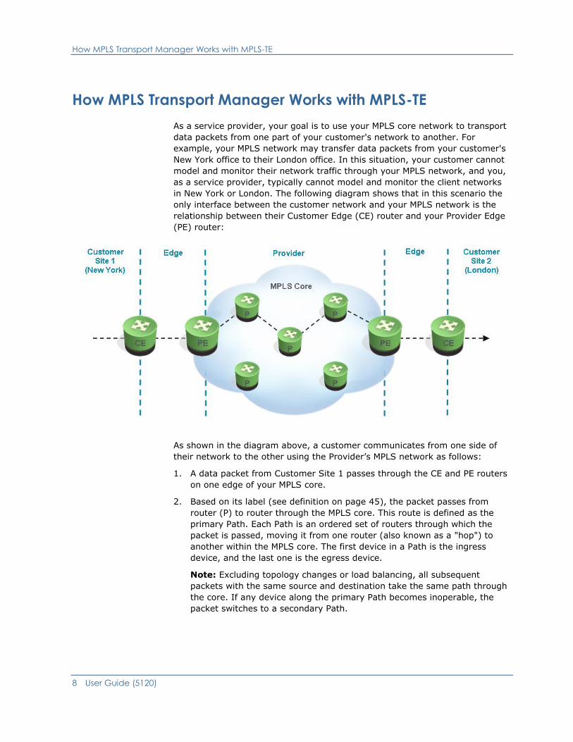
As a service provider, your goal is to use your MPLS core network to transport
data packets from one part of your customer's network to another. For
example, your MPLS network may transfer data packets from your customer's
New York office to their London office. In this situation, your customer cannot
model and monitor their network traffic through your MPLS network, and you,
as a service provider, typically cannot model and monitor the client networks
in New York or London. The following diagram shows that in this scenario the
only interface between the customer network and your MPLS network is the
relationship between their Customer Edge (CE) router and your Provider Edge
(PE) router:
As shown in the diagram above, a customer communicates from one side of
their network to the other using the Provider’s MPLS network as follows:
1. A data packet from Customer Site 1 passes through the CE and PE routers
on one edge of your MPLS core.
2. Based on its label (see definition on page 45), the packet passes from
router (P) to router through the MPLS core. This route is defined as the
primary Path. Each Path is an ordered set of routers through which the
packet is passed, moving it from one router (also known as a "hop") to
another within the MPLS core. The first device in a Path is the ingress
device, and the last one is the egress device.
Note: Excluding topology changes or load balancing, all subsequent
packets with the same source and destination take the same path through
the core. If any device along the primary Path becomes inoperable, the
packet switches to a secondary Path.
Devices Supported by MPLS Transport Manager
Chapter 1: MPLS Transport Manager 9
3. A packet passes through each hop in a Path, until it reaches the egress
device on the other side of the MPLS core.
4. From the egress device, the packet is passed to its next destination within
Customer Site 2.
MPLS Transport Manager models the relationships between the PE routers,
Paths, devices, and hops to monitor any changes that can negatively impact
the ability to move customer data packets through your MPLS core. For
example, if a router goes down, an LSP can change from its primary Path to a
secondary Path. Using traps and polling, MPLS Transport Manager is aware of
this change—it logs the event and may trigger an alarm (based on your
threshold values) to make sure that you are aware of the change. Knowing
that an LSP switched to a secondary Path can help you locate unreachable
devices and quickly assess their impact on your clients.
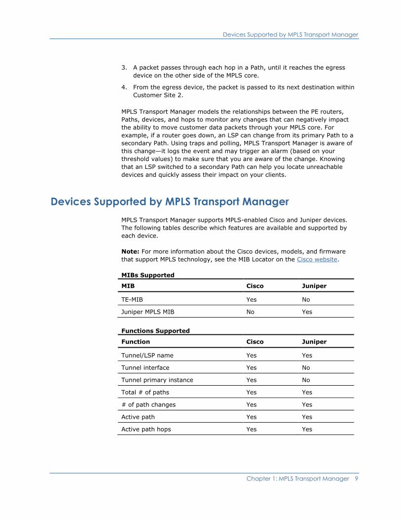
Devices Supported by MPLS Transport Manager
MPLS Transport Manager supports MPLS-enabled Cisco and Juniper devices.
The following tables describe which features are available and supported by
each device.
Note: For more information about the Cisco devices, models, and firmware
that support MPLS technology, see the MIB Locator on the Cisco website.
MIBs Supported
MIB Cisco Juniper
TE-MIB
Yes
No
Juniper MPLS MIB No Yes
Functions Supported
Function Cisco Juniper
Tunnel/LSP name
Yes
Yes
Tunnel interface Yes No
Tunnel primary instance Yes No
Total # of paths Yes Yes
# of path changes Yes Yes
Active path Yes Yes
Active path hops Yes Yes
System Requirements
10 User Guide (5120)
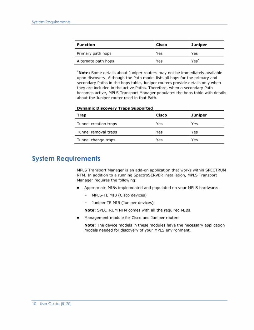
Function Cisco Juniper
Primary path hops
Yes
Yes
Alternate path hops Yes Yes*
*Note: Some details about Juniper routers may not be immediately available
upon discovery. Although the Path model lists all hops for the primary and
secondary Paths in the hops table, Juniper routers provide details only when
they are included in the active Paths. Therefore, when a secondary Path
becomes active, MPLS Transport Manager populates the hops table with details
about the Juniper router used in that Path.
Dynamic Discovery Traps Supported
Trap Cisco Juniper
Tunnel creation traps
Yes
Yes
Tunnel removal traps
Yes
Yes
Tunnel change traps Yes Yes
System Requirements
MPLS Transport Manager is an add-on application that works within SPECTRUM
NFM. In addition to a running SpectroSERVER installation, MPLS Transport
Manager requires the following:
■ Appropriate MIBs implemented and populated on your MPLS hardware:
– MPLS-TE MIB (Cisco devices)
– Juniper TE MIB (Juniper devices)
Note: SPECTRUM NFM comes with all the required MIBs.
■ Management module for Cisco and Juniper routers
Note: The device models in these modules have the necessary application
models needed for discovery of your MPLS environment.
Chapter 2: Configuring MPLS Transport Manager 11
Chapter 2: Configuring MPLS Transport
Manager
This section describes how to install and configure MPLS Transport Manager.
These are tasks that are typically performed only once per installation by the
MPLS Transport Manager administrator.
This section contains the following topics:
How to Install and Configure MPLS Transport Manager (see page 11)
Preparing Existing Devices for MPLS Transport Manager (see page 12)
Configure Port Polling on LSPs (see page 14)
Configure SpectroSERVER Processing of MPLS Traps (see page 15)
How to Install and Configure MPLS Transport Manager
MPLS Transport Manager is included in your SPECTRUM NFM extraction key.
When you install SPECTRUM NFM, the MPLS Transport Manager components
are automatically installed and available for use. However for best results, you
must adjust the configuration settings appropriately.
To install and configure MPLS Transport Manager properly, the administrator
must complete these tasks:
1. Install SPECTRUM NFM.
For existing SPECTRUM installations, perform an in-place installation to
help ensure the MPLS Transport Manager components are installed. MPLS
Transport Manager is not a distributed product, so install it on each
SpectroSERVER on which you want it to run. In a fault tolerant
environment, MPLS Transport Manager must be installed on each
SpectroSERVER to be fault tolerant.
Note: For specific installation instructions, see the Installation Guide
(5136).
2. Perform a device reconfiguration discovery for existing SPECTRUM NFM
installations only (see page 12).
Note: Perform this procedure on all SpectroSERVERs in a distributed
environment for which you want to use MPLS Transport Manager.
3. Configure port polling (see page 14). This option must be enabled for
impact to be calculated for ports which are part of an LSP. Although
enabled by default, you can disable port polling, if needed.
Preparing Existing Devices for MPLS Transport Manager
12 User Guide (5120)
4. Configure the SpectroSERVER traps (see page 15). These traps determine
how to manage various events that can occur in the MPLS core.
5. Configure impact weight values (see page 39). These impact weights help
to determine which alarms have the greatest impact on your MPLS
environment.
6. Configure settings for Path change alarms (see page 40). These settings
help to determine the severity of alarms generated when LSPs switch
Paths excessively.
Preparing Existing Devices for MPLS Transport Manager
For existing SPECTRUM NFM installations, the device models may not be using
the latest MPLS data. To help ensure that MPLS is fully supported, you must
perform a device reconfiguration discovery. This discovery reconfigures all
device models to include MPLS details, making them suitable for LSP discovery.
Over time, manufacturers may provide updated MIBs with additional MPLS
support. In this case, you can update only the affected device models when
the new MIBs become available. For example, the latest releases of JunOS
support a new Juniper MPLS MIB—the mplsLspList table was replaced by the
mplsLspListInfo table for new devices. For previously modeled devices that
support this MIB, a one-time migration step must be performed to create the
new application model with the updated table data.
Note: Perform these procedures for existing SPECTRUM NFM installations only.
Also, perform these procedures on all SpectroSERVERs in a distributed
environment for which you want to use MPLS Transport Manager.
More information:
How to Install and Configure MPLS Transport Manager (see page 11)
Discover Your LSPs (see page 19)
Preparing Existing Devices for MPLS Transport Manager
Chapter 2: Configuring MPLS Transport Manager 13
Reconfigure All Devices
If you have device models that existed in SPECTRUM NFM before MPLS
Transport Manager installation, then you must perform a device
reconfiguration discovery. This discovery reconfigures all device models to
include MPLS details, making them suitable for LSP discovery.
To reconfigure all previously existing device models for use with MPLS
Transport Manager
1. Open the main MPLS Transport Manager page (see page 18).
The main details page opens in the Contents panel for the selected MPLS
Transport Manager.
2. Click the Information tab in the Contents panel.
3. Expand the Configuration section.
4. Expand the LSP Discovery subsection.
LSP discovery options display.
5. Click the Run button in the Device Reconfiguration Discovery field.
The existing device models are reconfigured with MPLS data and ready for
LSP discovery.
More information:
How to Install and Configure MPLS Transport Manager (see page 11)
Reconfigure Selected Devices (see page 13)
Reconfigure Selected Devices
As manufacturers update their MIBs to improve MPLS support, you should
update those specific models in SPECTRUM NFM to use this updated MIB data.
This procedure describes how to perform a device reconfiguration discovery on
only selected devices.
To reconfigure selected device models with updated MPLS support
1. Select the Universe model in the OneClick Navigation panel.
Note: You can also search for the device models you want to reconfigure
using the Locater tab.
2. Select the List tab in the Contents panel.
All models in the Universe network are displayed.
3. Select the devices you want to update with new MIB data.
Configure Port Polling on LSPs
14 User Guide (5120)
4. Right-click the devices and select Reconfiguration, Rediscover SNMP MIBs.
When complete, a dialog opens confirming that the action succeeded.
5. Click OK.
The selected models are remodeled with the latest MIB information.
More information:
How to Install and Configure MPLS Transport Manager (see page 11)
Reconfigure All Devices (see page 13)
Configure Port Polling on LSPs
"Polling" for LSPs actually refers to polling the devices and interfaces on which
the LSP traverses. You can disable polling to limit network traffic, but it comes
at the loss of significant functionality in MPLS Transport Manager. Along with
traps, the polling mechanism is used to determine the health of the resources
that make up the MPLS Paths.
Note: This procedure is for the administrator only.
To configure port polling on LSPs
1. Open the main MPLS Transport Manager page (see page 18).
The main details page opens in the Contents panel for the selected MPLS
Transport Manager.
2. Click the Information tab in the Contents panel.
3. Expand the Configuration section.
4. Expand the LSP Discovery subsection.
LSP discovery options display.
5. Click the 'set' link for the Enable Port Polling option.
The value for the selected option becomes editable.
Note: Enabled by default, the polling option must be turned on for impact
to be calculated for ports which are part of an LSP.
6. Select the desired value for the field and press Enter.
MPLS Transport Manager is configured to poll LSPs according to your
selection.
More information:
How to Install and Configure MPLS Transport Manager (see page 11)
Configure SpectroSERVER Processing of MPLS Traps (see page 15)
Configure SpectroSERVER Processing of MPLS Traps
Chapter 2: Configuring MPLS Transport Manager 15
Configure SpectroSERVER Processing of MPLS Traps
If your MPLS-enabled devices are properly configured to send traps to the
SpectroSERVER host, you can use this trap data to create, delete, or update
LSPs. Some environments do not support the use of traps, and you can choose
to disable them. However, we recommend that you enable traps when
possible, because traps (along with polling) provide the best response to
network faults and outages.
Note: This procedure is for the administrator only.
To configure SpectroSERVER processing of MPLS traps
1. Open the main MPLS Transport Manager page (see page 18).
The main details page opens in the Contents panel for the selected MPLS
Transport Manager.
2. Click the Information tab in the Contents panel.
3. Expand the Configuration section.
4. Expand the LSP Discovery subsection.
LSP discovery options display.
5. Click the 'set' link for the following trap that you want to configure:
Create LSP on Trap
Creates a new LSP when the TunnelUp trap is received and the device
model already exists.
Default: Yes
Delete LSP on Trap
Deletes an existing LSP and its associated Path models when the
TunnelDown trap is received and the tunnel no longer exists in the
device.
Default: Yes
Update LSP on Trap
Deletes all Paths for an LSP and remodels the LSP when the
TunnelRerouted trap is received and an LSP model already exists for
the LSP.
Default: Yes
Example: When an LSP switches from the primary path to the
secondary path, the LSP Path models are deleted and remodeled to
display the updated Path information.
The value for the selected option becomes editable.

Configure SpectroSERVER Processing of MPLS Traps
16 User Guide (5120)
6. Select the desired value for the field and press Enter.
The selected trap is configured for SpectroSERVER processing.
More information:
How to Install and Configure MPLS Transport Manager (see page 11)
Configure Port Polling on LSPs (see page 14)

Chapter 3: Managing Your LSP Data 17
Chapter 3: Managing Your LSP Data
This section describes the basic tasks for discovering, viewing, and managing
the models associated with your MPLS infrastructure. Although discovery is an
administrator-only task, most of the tasks in this section are for general MPLS
Transport Manager operators.
This section contains the following topics:
Viewing LSP Details (see page 17)
View LSP Paths (see page 22)
View Hops in an LSP Path (see page 23)
Unmodeled Hops in MPLS Transport Manager (see page 24)
Model Names (see page 26)
Viewing LSP Details
The primary MPLS Transport Manager view is the OneClick Navigation view.
This application is not cross-server aware, so the MPLS Transport Manager
model is located within a landscape's hierarchy. The following example shows
where MPLS Transport Manager fits into the OneClick Navigation view and
shows the hierarchy of MPLS information:
[-] SpectroSERVER host
[-] MPLS Transport Manager
[-] Head-end device 1
[-] LSP 1
[-] Path 1
Device 1
Device 2
[+] Path 2
[+] Path 3
[+] LSP 2
[+] Head-end device 2
[+] Head-end device 3
[+] Universe
An MPLS environment can have hundreds of LSPs, making it difficult to
organize and display them logically. Therefore, MPLS Transport Manager
groups LSP details under the LSP head-end devices. The LSP head-end device
is a Provider Edge router device used to create the LspHead model in MPLS
Transport Manager. This model groups your LSPs by ingress device in the
OneClick Navigation panel, making it easier to view and locate data about your
LSPs within the MPLS environment.
Viewing LSP Details
18 User Guide (5120)
From the head-end device level, you can expand the navigation tree to view a
list of LSPs that begin from the selected head-end device. Expanding these
LSPs in the navigation tree displays a list of Paths within the selected LSP, and
expanding a Path displays specific devices used in the Path's hops.
Selecting any entry in the navigation tree displays details about the selection
within the Contents panel, and selecting items in the Contents panel displays
further details in the Component Detail panel.
To help determine the performance of your MPLS environment and your
adherence to customer SLAs, you can use the OneClick views to drill into
detailed information for each LSP, such as the following:
■ Primary and secondary Paths
■ Hops for each Path and their order
■ Ingress and egress devices for each LSP
■ Alarm state for all models, including the severity and impact
If you cannot find the information you need through the Navigation panel, you
can also search the MPLS Transport Manager data using the Locater tab.
More information:
Main Window for MPLS (see page 19)
Searching (see page 31)
Locater Tab for MPLS (see page 32)
Deleting Models (see page 27)
Open MPLS Transport Manager
To monitor your MPLS environment, you must first locate the main MPLS
Transport Manager page within OneClick. When you open this page, you can
access the features used to monitor the status of your MPLS performance.
To open the main MPLS Transport Manager page
1. Open the OneClick Console.
2. Click the Explorer tab in the Navigation panel.
3. Locate and expand your landscape in the Navigation panel and click MPLS
Transport Manager.
The main details page opens in the Contents panel for the selected MPLS
Transport Manager.
Viewing LSP Details
Chapter 3: Managing Your LSP Data 19
Discover Your LSPs
To monitor your MPLS environment, you must perform a discovery. LSP
discovery creates all device, LSP, and Path models, and these models give you
a view into the MPLS core that lets you monitor the health of your MPLS
infrastructure.
Note: This procedure is for the administrator only.
To discover your LSPs
1. Open the main MPLS Transport Manager page (see page 18).
The main details page opens in the Contents panel for the selected MPLS
Transport Manager.
2. Click the Information tab in the Contents panel.
3. Expand the Configuration section.
4. Expand the LSP Discovery subsection.
LSP discovery options display.
5. Click the Run button in the Discovery Status field.
SPECTRUM NFM discovers your MPLS infrastructure and creates all related
models. Your MPLS data is ready to view and monitor.
Note: Some details about Juniper routers may not be immediately
available upon discovery. Although the Path model lists all hops for the
primary and secondary Paths in the hops table, Juniper routers provide
details only when they are included in the active Paths. Therefore, when a
secondary Path becomes active, MPLS Transport Manager populates the
hops table with details about the Juniper router used in that Path.
More information:
Preparing Existing Devices for MPLS Transport Manager (see page 12)
How to Add Previously Unmodeled Hops (see page 25)
Main Window for MPLS
MPLS Transport Manager is integrated into SPECTRUM OneClick, and you
access the main view through the Explorer tab in the Navigation panel. This
tab provides a hierarchical view of the models used to display your MPLS data.
This tree structure helps you manage your customer SLAs and monitor LSP
performance by providing a quick way to view details and troubleshoot alarms
caused by devices used in your MPLS environment.
Viewing LSP Details
20 User Guide (5120)
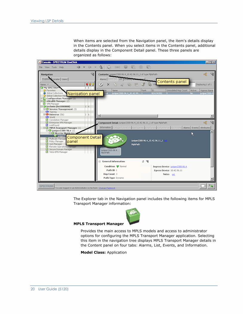
When items are selected from the Navigation panel, the item's details display
in the Contents panel. When you select items in the Contents panel, additional
details display in the Component Detail panel. These three panels are
organized as follows:
The Explorer tab in the Navigation panel includes the following items for MPLS
Transport Manager information:
MPLS Transport Manager
Provides the main access to MPLS models and access to administrator
options for configuring the MPLS Transport Manager application. Selecting
this item in the navigation tree displays MPLS Transport Manager details in
the Content panel on four tabs: Alarms, List, Events, and Information.
Model Class: Application
Viewing LSP Details
Chapter 3: Managing Your LSP Data 21
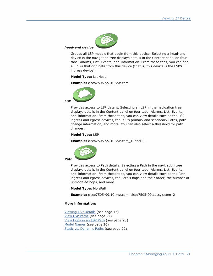
head-end device
Groups all LSP models that begin from this device. Selecting a head-end
device in the navigation tree displays details in the Content panel on four
tabs: Alarms, List, Events, and Information. From these tabs, you can find
all LSPs that originate from this device (that is, this device is the LSP's
ingress device).
Model Type: LspHead
Example: cisco7505-99.10.xyz.com
LSP
Provides access to LSP details. Selecting an LSP in the navigation tree
displays details in the Content panel on four tabs: Alarms, List, Events,
and Information. From these tabs, you can view details such as the LSP
ingress and egress devices, the LSP's primary and secondary Paths, path
change information, and more. You can also select a threshold for path
changes.
Model Type: LSP
Example: cisco7505-99.10.xyz.com_Tunnel11
Path
Provides access to Path details. Selecting a Path in the navigation tree
displays details in the Content panel on four tabs: Alarms, List, Events,
and Information. From these tabs, you can view details such as the Path
ingress and egress devices, the Path's hops and their order, the number of
unmodeled hops, and more.
Model Type: MplsPath
Example: cisco7505-99.10.xyz.com_cisco7505-99.11.xyz.com_2
More information:
Viewing LSP Details (see page 17)
View LSP Paths (see page 22)
View Hops in an LSP Path (see page 23)
Model Names (see page 26)
Static vs. Dynamic Paths (see page 22)

View LSP Paths
22 User Guide (5120)
View LSP Paths
When analyzing the performance of your MPLS environment, you may need to
view the Path details for a specific LSP. You can view details such as how many
Paths exist, what is the Path's rank (primary, secondary, and so on), what is
the alarm condition for each Path, and more. Viewing this information can help
you determine if you are meeting your customer SLAs or can reveal
opportunities for improving the performance of your LSP.
To view an LSP Path
1. Open the main MPLS Transport Manager page (see page 18).
The main details page opens in the Contents panel for the selected MPLS
Transport Manager.
2. Locate and click the LSP on the Explorer tab in the Navigation panel.
The LSP details display in the Contents panel.
3. Click the List tab.
All of the LSP's Paths display in the table, showing details for each.
More information:
Main Window for MPLS (see page 19)
Static vs. Dynamic Paths
Two path types exist in MPLS environments: static (that is, explicit) and
dynamic. A static path is an explicitly engineered path from a source device to
a destination device, whereas a dynamic path through the MPLS network is
computed by the head-end device, based on resource availability and routing
protocols.
When analyzing your LSP Paths, knowing the path type can help reveal
weaknesses in your MPLS environment and reveal opportunities to optimize
the performance of your Paths.
The Path type is available in two locations:
■ The List tab of an LSP's Contents pane
■ The Information tab of a Path's Component Details pane
More information:
Main Window for MPLS (see page 19)

View Hops in an LSP Path
Chapter 3: Managing Your LSP Data 23
Spotlighting LSP Paths
The spotlighting feature in OneClick lets you isolate and visualize model
relationships within your network that are not readily visible from the Topology
view. For example, the Topology view does not visually distinguish VLANs,
VPNs, or LSP Paths, making it more difficult to picture these relationships
within the context of your network. With spotlighting, these model
relationships are accentuated, showing you where they appear in the network
topology.
Using the spotlighting feature, you can select an LSP Path to view in the
Topology view. Viewing LSP Path information from this view can help you more
easily understand which devices make up the Path. From this view, you can
also see if any alarming devices are impacting the Path's performance.
Note: For more information about how to use spotlighting, see the OneClick
Console User Guide (5130).
View Hops in an LSP Path
When analyzing the performance of your MPLS environment, you may need to
view the hops in a specific LSP Path. You can view details such as the order of
the hops, the devices used for each hop, what is the alarm condition for each
modeled device, and more. Viewing this information can help you troubleshoot
alarms that occur for an LSP.
Note: Some details about Juniper routers may not be immediately available
upon discovery. Although the Path model lists all hops for the primary and
secondary Paths in the hops table, Juniper routers provide details only when
they are included in the active Paths. Therefore, when a secondary Path
becomes active, MPLS Transport Manager populates the hops table with details
about the Juniper router used in that Path.
To view hops in a Path
1. Open the main MPLS Transport Manager page (see page 18).
The main details page opens in the Contents panel for the selected MPLS
Transport Manager.
2. Locate and click the LSP Path on the Explorer tab in the Navigation panel.
The LSP Path details display in the Contents panel.

Unmodeled Hops in MPLS Transport Manager
24 User Guide (5120)
3. Click the Information tab.
4. Expand the Path Hops section.
All hops for the selected LSP Path are displayed in the table.
Note: You can also find a Path's hops on the List tab, but we recommend
the list on the Information tab. The Information tab displays the order of
the hops and displays the ingress/egress interfaces for each hop.
More information:
Main Window for MPLS (see page 19)
Unmodeled Hops in MPLS Transport Manager
LSP Paths can contain nodes that appear as unmodeled hops. These
unmodeled hops are easily recognized in the Path Hops table on the
Component Details Information tab. IPs of any unmodeled hops are provided
in the table, as shown:
Note: You can find paths with unmodeled hops by searching for all Paths and
sorting the results by "Unmodeled Hop Count" in descending order.

Unmodeled Hops in MPLS Transport Manager
Chapter 3: Managing Your LSP Data 25
Unmodeled hops can exist for any of the following reasons:
■ The device is not modeled in SPECTRUM
■ The device is modeled on a different landscape
■ The device is modeled but with an incorrect community name
Although MPLS Transport Manager can provide Path and hop information
without all devices modeled, SPECTRUM cannot determine the impact to your
MPLS environment and customer SLAs. If the device is not modeled, no alarms
appear for that device, making it much harder to figure out the cause of a Path
going down. If MPLS traps are not sent to the SpectroSERVER or if these traps
are disabled in MPLS Transport Manager, SPECTRUM may not even detect that
the Path is down at all. Therefore, it is always best to model all devices used in
your LSP Paths.
More information:
How to Add Previously Unmodeled Hops (see page 25)
View Hops in an LSP Path (see page 23)
Deleting Models (see page 27)
How Impact is Determined (see page 37)
How to Add Previously Unmodeled Hops
If an unmodeled device appears in a Path's hops, we recommend that you
model that device so that the LSP impact can be calculated for alarms
generated by the device. Unmodeled devices do not generate alarms and,
therefore, cannot provide impact data, making it more difficult to determine
accurately the priority of device outages involving your LSPs.
To get MPLS Transport Manager to display the device details in the Path Hops
table, follow these steps:
1. Model the device in OneClick using the IP address provided in the Path
Hops table.
Note: We recommend that you model all MPLS Path nodes on a single
server. Be sure that the node is modeled in the correct landscape, with the
correct community name.
2. Rebuild the MplsPath model. This task requires the following two steps:
a. Update the MPLS Path data by searching for and deleting all MplsPath
models that contain the unmodeled hop. This step is required because
rediscovering MPLS devices does not automatically display the newly
modeled device in the list of hops. The MplsPath model must be rebuilt
to update that device model information.

Model Names
26 User Guide (5120)
Note: You can find paths with unmodeled hops by searching for all
Paths and sorting the results by "Unmodeled Hop Count" in descending
order.
b. Run MPLS Transport Manager discovery (see page 19). The MplsPath
models are recreated, and the newly modeled device information
appears in the Path Hop table.
More information:
Deleting Models (see page 27)
Unmodeled Hops in MPLS Transport Manager (see page 24)
Model Names
During discovery, MPLS Transport Manager uses the following unique model
types to model your MPLS environment:
■ LspHead
■ LSP
■ MplsPath
These model types help to determine the names of your MPLS models. For LSP
models, MIBs determine the names. Therefore, these names are not editable
within MPLS Transport Manager. For LspHead models, the model name is
initially patterned after the LSP head-end device during discovery, using the
device model name as a prefix. Likewise, the MplsPath model name is
patterned after the LSP name. This naming scheme helps to identify the
relationships between these MPLS models and their related devices.
If a device or LSP model name changes and the corresponding LspHead or
MplsPath model name uses its prefix, the LspHead or MplsPath model name
automatically changes to match. For example, if you have a head-end device
named "juniper2300," the LspHead model name could be
"juniper2300.example.com." If the device name changes to "juniper2300_03,"
the LspHead model name becomes "juniper2300_03.example.com."
However, you may want to apply a unique name, such as a name that
corresponds to a primary customer or region for the LSP. You can edit the
LspHead and MplsPath model names manually, and these names do not
change automatically. For example, you can manually rename the LspHead
model name from "juniper2300_03.example.com" to "Router_NY_03." If the
name of the device in this example changes, the LspHead model name will not.
More information:
Main Window for MPLS (see page 19)
Model Names
Chapter 3: Managing Your LSP Data 27
Modify an LspHead or MplsPath Model Name
The LspHead model name is initially patterned after the LSP head-end device
during discovery, and the MplsPath model name is patterned after the LSP
name. However, you can apply a unique name, such as a name that
corresponds to a primary customer or region for the LSP. You can edit the LSP
Head and Path model names manually, and these names will not change
automatically.
Note: The LSP model names are not editable, because MIBs determine these
names.
To modify an LspHead or MplsPath model name
1. Open the main MPLS Transport Manager page (see page 18).
The main MPLS Transport Manager details page opens in the Contents
panel.
2. Locate and click the LSP Head-End or Path on the Explorer tab in the
Navigation panel.
The details display in the Contents panel and Component Detail panel.
3. Click the Information tab in the Component Detail panel.
4. Click the 'set' link for the model name that you want to modify.
The current name becomes editable.
5. Type the desired model name into the field and press Enter.
The selected model name is modified.
Deleting Models
Models can be deleted from OneClick at any time for several reasons, and
deleting these models can have various implications. First, deleting a head-end
model also deletes all models underneath in the MPLS Transport Manager
model hierarchy. An MPLS rediscovery is required to restore those models, if
needed.
Second, an administrator who does not monitor your MPLS environment can
decide that a router in his landscape does not need monitoring, so the
administrator deletes the device model for that router. If that device model is
the ingress router for one or more LSPs, the LspHead model is deleted. In this
case, all LSP and Path models below it are also deleted, as described in the
first scenario.

Model Names
28 User Guide (5120)
Some of these deleted models may have been used in LSPs or Paths, and the
MPLS Transport Manager administrator can decide to restore those models
(see page 25). For example, a device model that appears in a Path's hops can
be deleted and appear as an unmodeled hop, making it difficult to monitor the
performance of the LSP that includes that Path.
More information:
Viewing LSP Details (see page 17)
Unmodeled Hops in MPLS Transport Manager (see page 24)

Chapter 4: Monitoring Performance and SLAs 29
Chapter 4: Monitoring Performance and
SLAs
This section explains the information you need to monitor the performance of
your MPLS infrastructure and check your adherence to customer SLAs using
MPLS Transport Manager. This section is intended for general MPLS Transport
Manager operators.
This section contains the following topics:
Monitoring SLAs for MPLS Environments (see page 29)
Analyzing LSP Performance (see page 30)
Searching (see page 31)
Monitoring SLAs for MPLS Environments
For an ISP, continuity of service is crucial for each customer, which is why
client SLAs are often established. Although all service outages are not
avoidable, the customer relies on the ISP to keep the outages to a minimum,
adhering to the terms agreed upon in their SLA.
Monitoring an MPLS environment for adherence to customer SLAs can be
difficult. MPLS Transport Manager makes this task easier by monitoring the
performance of the MPLS devices and providing a way to view the relationship
of those devices to your LSPs and Paths. Depending on your needs, you can
monitor SLAs in one of the following ways:
■ Analyze your LSPs for performance
■ Determine if LSP service is interrupted
■ Determine which customers are affected by outages or poor performance
■ Search for a customer's LSPs to monitor their health
Some of these monitoring tasks are proactive (such as searching for specific
LSPs) and some are the result of an alarm triggered by a device in your MPLS
environment.
Although SLA information is not maintained in MPLS Transport Manager, you
can use the information you have about your SLAs, such as the specific
traffic-engineered LSPs used by a client, to determine which customers are
impacted by an alarm involving an MPLS device.

Analyzing LSP Performance
30 User Guide (5120)
More information:
MPLS Transport Manager Alarms (see page 35)
Analyzing LSP Performance
To measure the performance of your MPLS environment and the LSPs in the
environment, you must analyze the devices and interfaces used by the LSPs.
Their status helps to determine the overall health of your MPLS environment
and to decide if you must make changes to improve the performance.
The areas that you can monitor for LSP performance include the following:
■ Path changes—Excessive Path changes can indicate a problem with a
device or network connection in your LSP. For example, an LSP may switch
to the secondary path 90 percent of the time because a router on the
primary path is continually at maximum capacity. In this case, you can
analyze the devices and interfaces in the Path to determine the cause and
troubleshoot the problem before a service outage occurs on that LSP. MPLS
Transport Manager lets you specify a maximum threshold of Path changes
for an LSP. If the threshold is breached, an alarm is generated.
■ Device outages—If a device outage occurs and causes an alarm, you
need to know quickly if the outage has affected any LSPs in your
environment. If these devices are modeled in MPLS Transport Manager,
the alarm details display information about which LSPs are affected.
■ Alarms—All alarms generated from the MPLS environment can provide
insight into performance glitches. The impact of alarms generated for
device and interface models that affect LSPs is determined by a
combination of information, such as which LSP paths are affected (that is,
primary, secondary, and so on) and the number of LSPs impacted by the
alarm. These alarms can help you drill into the LSP details required to
analyze performance issues.
Note: Only device and interface alarms provide impact weight information.
Alarms against the Paths, LSPs, and LspHeads do not have the LSP impact
values.
More information:
MPLS Transport Manager Alarms (see page 35)
How Path Change Alarms Work (see page 40)
Searching
Chapter 4: Monitoring Performance and SLAs 31
Searching
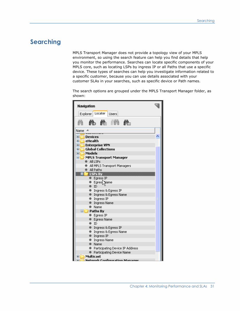
MPLS Transport Manager does not provide a topology view of your MPLS
environment, so using the search feature can help you find details that help
you monitor the performance. Searches can locate specific components of your
MPLS core, such as locating LSPs by ingress IP or all Paths that use a specific
device. These types of searches can help you investigate information related to
a specific customer, because you can use details associated with your
customer SLAs in your searches, such as specific device or Path names.
The search options are grouped under the MPLS Transport Manager folder, as
shown:

Searching
32 User Guide (5120)
For example, if you know the IP address or name of a specific router, you can
search for all LSP Paths that use it. Using the list of Paths affected by the
router can be useful when performing scheduled maintenance. You can change
your Paths to use a different router, or be sure that at least one secondary
Path is provided for each LSP before the maintenance. Also, you can give prior
notice to any customers affected by those Paths.
More information:
Viewing LSP Details (see page 17)
Locater Tab for MPLS (see page 32)
Search the MPLS Environment
When analyzing the performance of your MPLS environment, you can quickly
locate a specific LSP, Path, or find a group of LSPs, such as all LSPs by ingress
IP. These searches help you to view only the details required to effectively
monitor the performance of your MPLS network or monitor your customer
SLAs.
To search within your MPLS environment
1. Click the Locater tab in the OneClick Navigation panel.
2. Expand the MPLS Transport Manager folder and double-click the type of
search you want to perform.
If no additional search criterion is required, the search results display in
the Contents panel. If more criteria is required, a Search dialog opens.
3. Enter your search criteria and click OK.
The search results display in the Contents panel.
Locater Tab for MPLS
In addition to navigating your MPLS environment details on the Explorer tab,
you can also perform MPLS Transport Manager searches using the Locater tab
in the SPECTRUM OneClick Navigation panel. Detailed searches can help you
investigate information related to a specific customer, because you can use
details associated with your customer SLAs in your searches, such as specific
device or Path names.
Searching
Chapter 4: Monitoring Performance and SLAs 33
The Locater tab in the Navigation panel includes the following searches for
MPLS Transport Manager information:
All LSPs
Locates all LSPs that have been modeled in the SPECTRUM database for
the network. Although MPLS Transport Manager does not include the
distributed intelligence provided in SPECTRUM, this option searches
multiple landscapes by letting you select multiple SpectroSERVERs in the
search parameters.
All MPLS Transport Managers
Locates all MPLS Transport Manager installations in a list of landscapes you
select for the search.
Note: There can never be more than one MPLS Transport Manager per
landscape.
All Paths
Locates all Paths that have been modeled in the SPECTRUM database for
the network.
LSPs By
Locates specific LSPs that meet the search criteria for the following search
types:
■ Egress IP
■ Egress Name
■ ID
■ Ingress & Egress IP
■ Ingress & Egress Name
■ Ingress IP
■ Ingress Name
■ Name
Paths By
Locates specific Paths in your LSPs that meet the search criteria for the
following search types:
■ Egress IP
■ Egress Name
■ ID
■ Ingress & Egress IP
■ Ingress & Egress Name
■ Ingress IP

Searching
34 User Guide (5120)
■ Ingress Name
■ Name
■ Participating Device IP Address
■ Participating Device Name
More information:
Viewing LSP Details (see page 17)
Chapter 5: Responding to Alarms 35
Chapter 5: Responding to Alarms
This section explains the types of alarms generated for MPLS Transport
Manager devices and how to manage them. Although configuring impact
weights is an administrator-only task, most of this section is intended for
general MPLS Transport Manager operators.
This section contains the following topics:
MPLS Transport Manager Alarms (see page 35)
View the LSP Impact of an Alarm (see page 36)
How Path Change Alarms Work (see page 40)
MPLS Transport Manager Alarms
To alert you to problems within your monitored networks, SPECTRUM
generates alarms. When monitoring your MPLS environment, your MPLS
Transport Manager models display an alarm state for the following conditions:
■ A device or interface used within an LSP is down
Device or interface models generate these alarms when they are reported
as down. The impacted LSPs and Paths also display an alarm color and
details on the Alarm tab to help you identify the source of the problem.
Likewise, the device or interface alarm displays LSP impact details on the
Impact tab, such as the following:
– The number of LSPs affected
– The total LSP impact of the alarm (that is, the LSP impact value
without other types of impact, such as service impact or management
lost impact)
– A few details about the affected LSPs, such as their name, condition,
ID, and so on
In MPLS Transport Manager, the LSP impact weight settings determine how
much impact value is added to a device or interface alarm's total impact
when an LSP uses that device or interface. Adding these weight values can
help determine the priority of your devices or interfaces.
Note: Only device and interface alarms provide impact weight information.
Alarms against the Paths, LSPs, and LspHeads do not have the LSP impact
values.
View the LSP Impact of an Alarm
36 User Guide (5120)
■ Paths are switching too frequently
An LSP that is switching Paths too frequently can indicate a network
problem for you to address. In MPLS Transport Manager, there are two
types of Path change alarms:
– Aggregate Path change alarms—The LSP head-end model generates
these alarms when the Paths in the LSPs grouped under that head-end
model collectively exceed a threshold value for Path changes. The
aggregate Path change alarm settings help to determine the threshold
value that triggers an alarm for these Path changes.
– Per LSP (that is, non-aggregate) Path change alarms—An individual
LSP model generates these alarms when Path changes for the LSP
exceeds a threshold number within a specified time interval. You can
configure the Path change alarm settings for each LSP to determine
when the LSP triggers an alarm.
More information:
Monitoring SLAs for MPLS Environments (see page 29)
Analyzing LSP Performance (see page 30)
How Impact is Determined (see page 37)
How Path Change Alarms Work (see page 40)
View the LSP Impact of an Alarm
When devices or interfaces used in an LSP trigger an alarm, you can view the
impact of the alarm on your LSP. Knowing which LSPs are affected by an alarm
can help you determine if a customer SLA is in jeopardy and determine which
alarms have the highest priority. To view the impact to your LSPs, you have
the following options:
■ From an LSP Path model, view the devices or interfaces in an alarm state
that are causing it to perform poorly.
■ From a device or interface model, view a list of LSPs affected by an alarm.
This procedure describes the first option—how to view impact details from the
LSP Path model.
To use the LSP model to view the impact of an alarm in your MPLS
environment
1. Open the main MPLS Transport Manager page (see page 18).
The main details page opens in the Contents panel for the selected MPLS
Transport Manager.
2. Locate the alarming LSP Path on the Explorer tab in the Navigation panel.
The LSP Path details display in the Contents panel.
View the LSP Impact of an Alarm
Chapter 5: Responding to Alarms 37
3. Click the Alarms tab.
Alarms related to the selected LSP Path are displayed.
4. Select an alarm from the table.
Details about the alarm are displayed in the Component Detail panel.
5. Click the Impact tab.
The impact details for the selected alarm are displayed.
How Impact is Determined
Deciding which device and interface alarms cause the greatest impact to your
LSPs can be difficult, because the impact depends on how the device or
interface is used within your LSP Paths. For example, problematic devices used
in an LSP's primary path are much more significant than problematic devices in
a secondary path.
The goal of the MPLS Transport Manager impact system is to evaluate and
rank device and interface outages in respect to LSPs. For example, a device
outage can affect a number of LSPs which would make that device outage
more serious than a device outage which affects only one LSP, assuming all
LSPs are equal.
Note: In the impact calculation, MPLS Transport Manager does not prioritize
one LSP as being more important than another. If your SLAs are prioritized,
you may need to further calculate the alarms priority by considering your SLA
data outside of SPECTRUM.
To help prioritize the alarms affecting your LSPs, you can assign impact
weights for the following situations:
■ All LSP Paths are down
■ An LSP has switched from using the Primary Path to a secondary Path
■ At least one secondary LSP Path is down
When these situations occur, a corresponding impact weight is added to the
total impact value for the device or interface alarm. The model with the
highest total impact weight shows which alarm has the most impact on the
LSPs in your MPLS environment.
Note: Only device and interface alarms provide impact weight information.
Alarms against the Paths, LSPs, and LspHeads do not have the LSP impact
values.

View the LSP Impact of an Alarm
38 User Guide (5120)
Assuming that you use the default impact weight values, the following example
shows how MPLS Transport Manager calculates the LSP impact weights for
down devices that are used in your LSPs:
1. Device A is used in the primary Path of only LSP 1. When it goes down, it
causes LSP 1 to switch to a secondary Path. The default Switched LSP
Weight value (10) is added to the total impact value for the device alarm.
The total LSP impact value added for this situation is 10.
2. Device B is used in two secondary Paths for LSP 1. The default At Risk LSP
Weight value (5) is added only once, even though the device appears in
two secondary Paths. Only one value is counted per LSP, which is always
the most severe impact weight value. So the total LSP impact value added
for this situation is 5.
3. Device C is used in a secondary Path for LSP 1 and LSP 2. The default At
Risk LSP Weight value (5) is added twice to the total impact value for the
device alarm (one for each affected LSP). So, the total LSP impact value
added for this situation is 10.
4. Device D is used in the primary Path for LSP 1 and one secondary Path for
LSP 2. LSP 1 switches to an unaffected secondary Path, which adds impact
weight for the Switched LSP Weight (10). The At Risk LSP Weight value (5)
is added for the affected secondary Path for LSP 2. So, the total LSP
impact value for this scenario is 15.
5. Device E is used in all Paths for LSP 1, which includes the primary Path and
two secondary Paths. Because all Paths are down, the default Down LSP
Weight value (100) is added to the total impact value for the device alarm.
So, the total LSP impact value added for this situation is 100.
In this scenario, Device E would have the highest priority, because it causes
the highest total LSP impact value.
Note: LSP impact weights are only one factor contributing to the total impact
weight for an alarm. The total impact value for an alarm can include additional
impact values caused by other conditions not related to your LSP.
More information:
Unmodeled Hops in MPLS Transport Manager (see page 24)
View the LSP Impact of an Alarm
Chapter 5: Responding to Alarms 39
Customize Impact Weights for Alarms
You can assign custom impact weights for three types of LSP problems. These
impact weights help determine the alarm level for devices and interfaces used
in your LSPs, so you can more quickly identify which devices and interfaces
must be resolved first.
Note: This procedure is for the administrator only.
To customize impact weights for your LSP alarms
1. Open the main MPLS Transport Manager page (see page 18).
The main details page opens in the Contents panel for the selected MPLS
Transport Manager.
2. Click the Information tab in the Contents panel.
3. Expand the Configuration section.
4. Expand the LSP Impact subsection.
LSP impact options display.
5. Click the 'set' link for the following impact weight options that you want to
configure:
Down LSP Weight
Defines the value added to a device or interface alarm's total impact
weight when that device or interface is used within an LSP that is
reporting all Paths are down.
Default: 100
Limits: Integers greater than or equal to 0
Switched LSP Weight
Defines the value added to a device or interface alarm's total impact
weight when that device or interface is used within an LSP that has
switched from its primary Path to another one.
Default: 10
Limits: Integers greater than or equal to 0
At Risk LSP Weight
Defines the value added to a device or interface alarm's total impact
weight when that device or interface is used within an LSP that is
reporting at least one of its secondary Paths is down.
Default: 5
Limits: Integers greater than or equal to 0
The value for the selected option becomes editable.
How Path Change Alarms Work
40 User Guide (5120)
6. Enter the desired value for the field and press Enter.
The selected impact weight is customized for LSP alarms.
More information:
How to Install and Configure MPLS Transport Manager (see page 11)
How Path Change Alarms Work
An LSP that is switching Paths too frequently can indicate a network problem
to address. MPLS Transport Manager can monitor the number of Path changes
for each LSP, and it can monitor the aggregate Path changes for all LSPs
grouped under an LSP head-end device. Understanding the difference between
the Per LSP (that is, non-aggregate) and the aggregate method for monitoring
Path changes can help you determine which method you prefer for your MPLS
environment.
When monitoring Per LSP Path change alarms, the individual LSP generates
the alarms. This method works as follows:
1. For each LSP you want to monitor, the administrator configures the Path
Change Information, which includes specifying the Path Changes Window
interval and the Path Changes Threshold value.
2. For each Path Changes Window interval, MPLS Transport Manager
performs these steps:
a. Counts how many times a Path within the LSP switches Paths, either
from the primary Path to a secondary Path or vice versa.
b. Notes the total number of changes at the end of the interval.
Note: The number is also added to the # Path Changes field, which
represents the number of Path changes since the head-end device was
last booted. This value is not used when calculating the Path change
alarms.
c. Compares the # Path Changes field with the threshold value selected.
d. Triggers a critical alarm if the number of Path changes is greater than
the threshold value.
3. MPLS Transport Manager repeats step 2 for each Path change interval and
adjusts the alarm, as needed. Therefore, if subsequent intervals do not
exceed the threshold value, the alarm is cleared. However, an event is
recorded to the event history for each Path change alarm.
How Path Change Alarms Work
Chapter 5: Responding to Alarms 41
When monitoring aggregate Path change alarms, the LSP head-end device
generates the alarms. This method can generate more than one alarm severity
and works as follows:
1. For each LSP head-end device that you want to monitor, the administrator
configures the Aggregate Path Change Alarms settings for the MPLS
Transport Manager installation. These settings include threshold
percentages for three alarm severities and the Path Change Window
interval.
2. For each Path Change Window interval, MPLS Transport Manager performs
these steps:
a. Counts the number of Path switches for all LSPs grouped under an
LspHead device.
b. Calculates the percentage of Path changes as follows:
(Total Path changes ÷ Total LSPs in the LspHead) x 100 = Percentage of Path
changes
c. Compares the percentage to the threshold values for each alarm
severity.
d. Triggers an alarm with a severity that corresponds to the highest
threshold breached.
Note: If multiple thresholds are configured with the same value, the
highest level of alarm is generated.
3. MPLS Transport Manager repeats step 2 for each Path change interval and
adjusts the alarm as needed. Therefore, if subsequent intervals breach a
lower alarm threshold, the alarm severity is adjusted accordingly. Also, if
Path changes in an interval do not exceed any threshold values, the alarm
is cleared. However, events are recorded in the event history for all Path
change alarms.
More information:
How to Install and Configure MPLS Transport Manager (see page 11)
Analyzing LSP Performance (see page 30)

How Path Change Alarms Work
42 User Guide (5120)
Customize Aggregate Path Change Alarm Settings
LSP Path changes are common, but excessive changes cause an alarm that can
indicate a performance problem to address. Customizing the aggregate path
change alarm percentages can help you sort these Path change alarms by
severity.
To customize aggregate alarm settings for excessive LSP Path changes
1. Open the main MPLS Transport Manager page (see page 18).
The main details page opens in the Contents panel for the selected MPLS
Transport Manager.
2. Click the Information tab in the Contents panel.
3. Expand the Configuration section.
4. Expand the Aggregate Path Change Alarms subsection.
Path change alarm options display.
5. Click the 'set' link for the following options that you want to configure:
Minor Threshold %
Defines the threshold percentage for Path changes that triggers a
minor alarm. The percentage of Path changes refers to the ratio of
Path changes to the total number of Paths within an LspHead model
during a single Path Change Window interval.
Default: 3
Limits: Integers 0-100
Note: A value of 0 causes any Path changes to generate an alarm with
this severity.
Major Threshold %
Defines the threshold percentage for Path changes that triggers a
major alarm. The percentage of Path changes refers to the ratio of
Path changes to the total number of Paths within an LspHead model
during a single Path Change Window interval.
Default: 5
Limits: Integers 0-100
Note: A value of 0 causes any Path changes to generate an alarm with
this severity.
How Path Change Alarms Work
Chapter 5: Responding to Alarms 43
Critical Threshold %
Defines the threshold percentage for Path changes that triggers a
critical alarm. The percentage of Path changes refers to the ratio of
Path changes to the total number of Paths within an LspHead model
during a single Path Change Window interval.
Default: 10
Limits: Integers 0-100
Note: A value of 0 causes any Path changes to generate an alarm with
this severity.
Path Change Window (sec)
Defines the time interval in seconds for which the percentage of Path
changes is calculated.
Default: 60
Limits: Integers greater than or equal to 30
Note: Only one alarm is generated for a Path change window interval,
even if multiple threshold values are set to the same number. For
example, if the Minor Threshold % and Major Threshold % values are both
set to 5, only a major alarm is generated if the threshold value is
breached. The minor alarm is not created.
The value for the selected option becomes editable.
6. Enter the desired value for the field and press Enter.
The selected Path change alarm setting is customized.
Customize Per LSP Path Change Alarms
LSP Path changes are common, but excessive changes cause an alarm that can
indicate a performance problem to address. Customizing the path change
alarm settings for each LSP model determines when the LSP triggers an alarm.
To customize Per LSP alarm settings for excessive LSP Path changes
1. Locate and select an LSP in the OneClick Navigation panel.
Details for the selected LSP appear in the Contents panel.
2. Click the Information tab in the Contents panel.
3. Expand the Path Change Information section.
Path change alarm options display.

How Path Change Alarms Work
44 User Guide (5120)
4. Click the 'set' link for the following options that you want to configure:
Path Changes Threshold
Defines the threshold number of Path changes allowed for an LSP. If
the number of Path changes exceeds this value within the path change
window interval, the LSP generates a critical alarm.
Default: 5
Limits: Integers greater than or equal to 0
Note: A value of 0 causes any Path changes to generate an alarm with
this severity.
Path Change Window (sec)
Defines the time interval in seconds for which the percentage of Path
changes is calculated.
Default: 60
Limits: Integers greater than or equal to 30
The value for the selected option becomes editable.
Note: The # Path Changes field is informational only. It is a
non-configurable field that specifies the total number of Path changes since
the LSP ingress device was last booted. This number can give you an idea
of the frequency of the Path changes.
5. Enter the desired value for the field and press Enter.
The selected Path change alarm setting is customized.

Glossary 45
Glossary
head-end device
The LSP head-end device is a Provider Edge router device used to create the
LspHead model in MPLS Transport Manager. This model groups your LSPs by
ingress device in the OneClick Navigation panel, making it easier to view and
locate data about your LSPs within the MPLS environment.
label
A label is a fixed-size field contained in a packet header that can be used as an
exact-match key in determining how to forward a protocol data unit.
Label Switch Router (LSR)
A Label Switch Router (LSR) is a router in an MPLS network that switches the
routing label on a data packet before forwarding it to the next hop in the LSP.
The LSR uses a look-up table to determine the new label.
Label Switched Path (LSP)
A Label Switched Path (LSP) is the path within the MPLS network along which
labeled packets are forwarded. Packets forwarded using a label are forwarded
along the same path as other packets using the same label.
Multiprotocol Label Switching (MPLS)
Multiprotocol Label Switching (MPLS) refers to a group of technologies that
marries IP to Layer 2 technologies (such as ATM) by overlaying a protocol on
top of IP networks.
Path
In an MPLS environment, a Path is the route taken by a data packet through a
series of devices in the network. This route is defined hop by hop.
Service Level Agreement (SLA)
A Service Level Agreement (SLA) is typically a contractual agreement between
a business and its subscribers guaranteeing a specified level of service, such as
99.9 percent availability. An SLA sometimes contains a penalty clause for
noncompliance.
Traffic Engineering (TE)
Traffic Engineering (TE) is the application of constraint-based routing in which
a traffic engineer uses a set of link characteristics to select a route and assigns
specific traffic to that route.


Index 47
Index
A
alarms
aggregate Path change • 35, 40, 42
configuring • 11, 39, 40, 42, 43
impact • 36, 39
in MPLS Transport Manager • 8, 24, 30, 35
Per LSP Path change • 35, 40, 43
viewing • 17, 22, 23, 30
application models • 19
C
Cisco devices • 9, 10, 11
Component Details panel
MPLS Transport Manager in the • 17, 19
configuring
alarms • 11, 39, 40, 42, 43
devices for MPLS • 12, 13, 25
impact weights • 11, 39
MPLS Transport Manager • 11
Path change alarms • 40, 42, 43
polling • 11, 14
traps • 11, 15
contacting technical support • iii
Contents panel
MPLS Transport Manager in the • 17, 19
Customer Edge (CE) router
in MPLS Transport Manager • 8
customer router • 8
customer support, contacting • iii
D
deleting
models • 27
devices
Cisco • 9, 10
discovery • 11, 12, 13
down • 8, 25, 29, 30, 35, 37
head-end • 17, 40, 45
Juniper • 9, 10, 19, 23
MPLS-enabled • 9
reconfiguring • 12, 13, 25
discovery
device reconfiguration for MPLS • 11, 12,
13, 25
LSP • 19
Paths • 25
distributed environment
in MPLS Transport Manager • 11
dynamic Paths • 22
E
egress device • 8, 17, 19, 32
F
fault tolerance
in MPLS Transport Manager • 11, 24
H
head-end device • 17, 19, 22, 23, 27, 40, 45
hops
defined • 8
unmodeled • 24, 25, 27
viewing • 17, 19, 23
I
impact
analyzing • 30, 36, 37
configuring • 11, 39
determining • 24, 35, 37
weights • 11, 30, 35, 39
ingress device • 8, 17, 22, 32, 45
installing
MPLS Transport Manager • 11
J
Juniper devices
Juniper MPLS MIB • 9, 11, 12
secondary Path details • 19, 23
supported in MPLS Transport Manager • 9
L
Label Switch Router (LSR) • 45
Label Switched Path, see also LSP • 45
label, in MPLS • 45
Locater tab
MPLS Transport Manager on the • 31, 32
LSP
changes • 8, 15
defined • 45
discovery • 13, 19
48 User Guide (5120)
impact • 35, 36, 37
model • 19, 26, 27
Paths • 8, 22, 23
polling • 11, 14
spotlighting • 23
traps • 15
viewing • 17, 19, 22, 31, 32
LspHead model • 17, 19, 26, 27, 45
M
MIB
features • 9
Juniper MPLS MIB • 9, 10
MIB Locator • 9
TE-MIB • 9, 10
updates • 12, 13
models
application • 19
deleting • 27
modifying • 27
MPLS • 17, 19, 26
naming • 25, 27
MPLS
alarms • 35
core • 8, 19
defined • 45
devices supported • 9
discovery • 19, 25
overview • 7, 8
performance monitoring • 29, 30, 31, 37
traffic engineering • 7, 8
MPLS Transport Manager
configuring • 11
devices supported • 9
discovery • 19, 25, 27
how it works • 8
installing • 11
opening • 18, 19
SPECTRUM NFM and • 7, 10, 11, 12, 19
system requirements • 11
mplsLspList table • 12
mplsLspListInfo table • 12
MplsPath model • 19, 25, 26, 27
Multiprotocol Label Switching, see also MPLS •
45
N
naming
models • 26, 27
Navigation panel
MPLS Transport Manager in the • 17, 18,
19, 32
O
OneClick
MPLS Transport Manager and • 11, 17, 19,
32
outage, device • 8, 25, 29, 30, 35, 37
P
Path
changes • 8, 9, 11, 17, 30, 35, 40
defined • 45
dynamic • 22
hops • 8, 9, 23, 24
in MPLS • 8, 17
LSP • 8, 18, 23
static • 22
types of • 22
viewing • 19, 22, 23, 31, 32
performance
monitoring • 24, 29, 30, 31, 37
polling
configure • 11, 14
in MPLS Transport Manager • 8
ports
polling • 11, 14
Provider Edge (PE) router
in MPLS Transport Manager • 8
R
routers
customer • 8
Customer Edge (CE) • 8
Provider Edge (PE) • 8
S
searching
MPLS • 31, 32
Paths • 23, 24
unmodeled hops • 24
Service Level Agreement, see also SLA • 45
service providers • 7, 8
SLA
defined • 45
monitoring • 7, 24, 29, 37
SpectroSERVER
MPLS Transport Manager and • 11, 12

Index 49
traps • 11, 15
SPECTRUM NFM
MPLS Transport Manager and • 7, 11, 12,
19
spotlighting
LSP Paths • 23
static Paths • 22
support, contacting • iii
system requirements • 10
T
technical support, contacting • iii
TE-MIB • 9, 11
Traffic Engineering (TE) • 7, 8, 45
Traffic Engineering, see also TE • 45
traps
configuring • 11, 15
in MPLS Transport Manager • 8, 9, 11, 15
TunnelDown trap • 15
TunnelRerouted trap • 15
TunnelUp trap • 17
U
unmodeled hops • 24, 25, 27