emi and emc - basic concepts - desy€¦ · emi and emc – basic concepts the absence of...
TRANSCRIPT
EMI and EMC – Basic Concepts The absence of Electromagnetic Interference (EMI) in a system is
called Electromagnetic Compatibility (EMC).
I am trying to ensure this state for the European XFEL facility (work package 39).
If you find this an entertaining afternoon, more talks can be hooked in indicated places.
Herbert Kapitza (FLA) MDI Technical Forum DESY, 02.03.12
Herbert Kapitza | MDI Technical Forum | 02.03.12 | Seite 2
Noise, Interference and Compatibility
> EM: electromagnetic
> EM noise: All electric signals in our system, except the ones we‘re interested in. It is extremely difficult – if not impossible – to have no noise in a system.
> EM interference (EMI): The unwanted effect of EM noise interfering with our signals.
> EM compatibility (EMC): Here I like to cite the definition from the European EMC directive 2004/108/EC: EM compatibility means the ability of equipment to function satisfactorily in its EM environment without introducing intolerable EM disturbances to other equipment in that environment. A remarkably clear sentence in a legal text!
EMC implies a balance: Don‘t disturb others and don‘t get disturbed by them.
For better understanding, let’s start with some definitions:

Herbert Kapitza | MDI Technical Forum | 02.03.12 | Seite 3
The Evolution of EM Noise
(1) Radio and TV: Before 1984 three TV programs were broadcasted in Germany. With the advent of cable and satellite TV the number of programs (not their quality) exploded. New territories in the EM spectrum were occupied.
Why has EMC more and more become an issue in the past decades? It is interesting to look at the evolution of randomly selected EM subjects:
(2) Telecommunication: This telephone inside the DESY tunnel must be from the 1960s when only Big Bosses had “mobile” phones installed in their cars. Today we have the atmosphere filled with EM smog from cell phones, WLAN etc. But imagine the ionizing radiation hardness of this black thing

Herbert Kapitza | MDI Technical Forum | 02.03.12 | Seite 4
The Evolution of EM Noise
(3) Automotive: My 1977 beetle had the following electric parts: battery, generator, ignition system, lamps, horn, rear window heating, radio. Nowadays almost everything is operated electrically and there are many intelligent assistant systems: A modern Fiat Panda has more computing power embedded than the DESY computing center of 1977 (IBM 370/168). Cars are among the toughest EMI places.
(4) Power supply: For a long time the majority of loads in the power grid was linear, i.e. composed of R, C, L. Today’s switched power supplies are energy-efficient but leave a lot of noise in the mains due to their pulsed current consumption. more
Herbert Kapitza | MDI Technical Forum | 02.03.12 | Seite 5
The Evolution of EM Noise
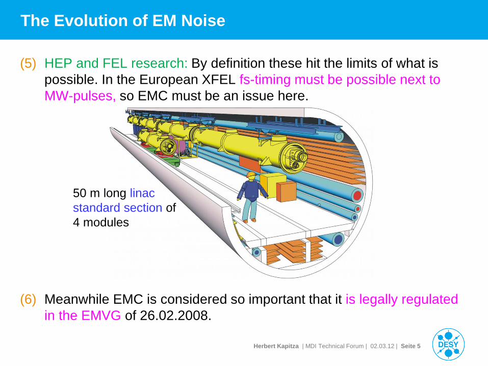
(5) HEP and FEL research: By definition these hit the limits of what is possible. In the European XFEL fs-timing must be possible next to MW-pulses, so EMC must be an issue here.
(6) Meanwhile EMC is considered so important that it is legally regulated in the EMVG of 26.02.2008.
50 m long linac standard section of 4 modules
Herbert Kapitza | MDI Technical Forum | 02.03.12 | Seite 6
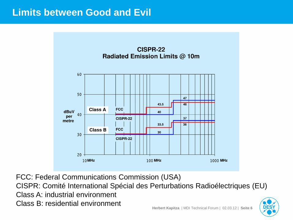
Limits between Good and Evil
FCC: Federal Communications Commission (USA) CISPR: Comité International Spécial des Perturbations Radioélectriques (EU) Class A: industrial environment Class B: residential environment
Herbert Kapitza | MDI Technical Forum | 02.03.12 | Seite 7
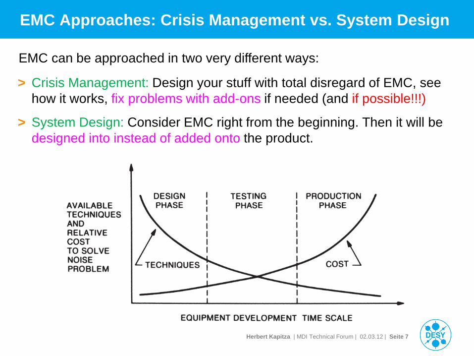
EMC Approaches: Crisis Management vs. System Design
> Crisis Management: Design your stuff with total disregard of EMC, see how it works, fix problems with add-ons if needed (and if possible!!!)
> System Design: Consider EMC right from the beginning. Then it will be designed into instead of added onto the product.
EMC can be approached in two very different ways:

Herbert Kapitza | MDI Technical Forum | 02.03.12 | Seite 8
Example: XFEL Tunnel Grounding
from the DESY Particle Physics Annual Report 2010
more
Herbert Kapitza | MDI Technical Forum | 02.03.12 | Seite 9
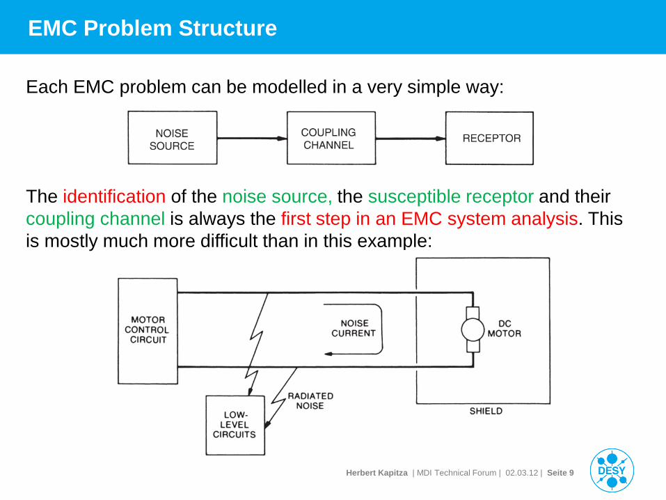
EMC Problem Structure
Each EMC problem can be modelled in a very simple way:
The identification of the noise source, the susceptible receptor and their coupling channel is always the first step in an EMC system analysis. This is mostly much more difficult than in this example:
Herbert Kapitza | MDI Technical Forum | 02.03.12 | Seite 10
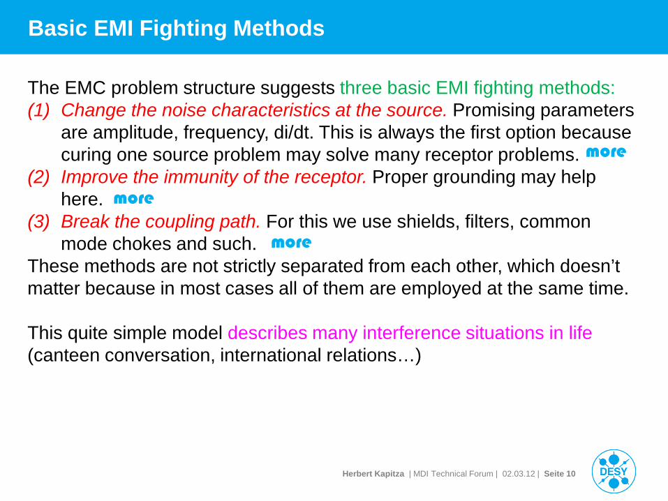
Basic EMI Fighting Methods
The EMC problem structure suggests three basic EMI fighting methods: (1) Change the noise characteristics at the source. Promising parameters
are amplitude, frequency, di/dt. This is always the first option because curing one source problem may solve many receptor problems.
(2) Improve the immunity of the receptor. Proper grounding may help here.
(3) Break the coupling path. For this we use shields, filters, common mode chokes and such.
These methods are not strictly separated from each other, which doesn’t matter because in most cases all of them are employed at the same time. This quite simple model describes many interference situations in life (canteen conversation, international relations…)
more
more
more
Herbert Kapitza | MDI Technical Forum | 02.03.12 | Seite 11
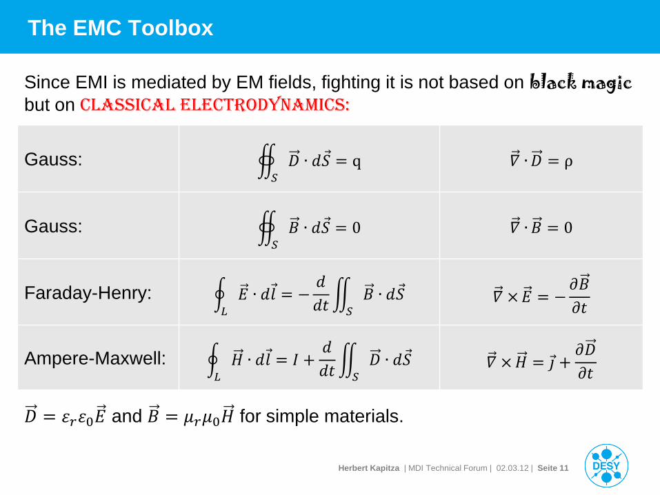
The EMC Toolbox
Gauss: 𝐷 ∙ 𝑑𝑆𝑆
= q 𝛻 ∙𝐷 = ρ
Gauss: 𝐵𝑆
∙ 𝑑𝑆 = 0 𝛻 ∙ 𝐵 = 0
Faraday-Henry: 𝐸 ∙ 𝑑𝑙𝐿
= −𝑑𝑑𝑑 𝐵
𝑆∙ 𝑑𝑆 𝛻 ×𝐸 = −
𝜕𝐵𝜕𝑑
Ampere-Maxwell: 𝐻 ∙ 𝑑𝑙𝐿
= 𝐼 +𝑑𝑑𝑑 𝐷
𝑆∙ 𝑑𝑆 𝛻 ×𝐻 = 𝚥 +
𝜕𝐷𝜕𝑑
Since EMI is mediated by EM fields, fighting it is not based on black magic but on classical electrodynamics:
𝐷 = 𝜀𝑟𝜀0𝐸 and 𝐵 = 𝜇𝑟𝜇0𝐻 for simple materials.
Herbert Kapitza | MDI Technical Forum | 02.03.12 | Seite 12
The EMC Toolbox
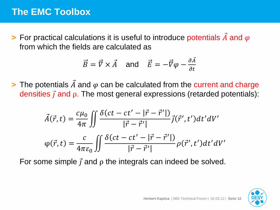
> For practical calculations it is useful to introduce potentials 𝐴 and 𝜑 from which the fields are calculated as
𝐵 = 𝛻 × 𝐴 and 𝐸 = −𝛻𝜑 − 𝜕𝐴𝜕𝜕
> The potentials 𝐴 and 𝜑 can be calculated from the current and charge densities 𝚥 and ρ. The most general expressions (retarded potentials):
𝐴 𝑟, 𝑑 =𝑐𝜇04𝜋
𝛿 𝑐𝑑 − 𝑐𝑑′ − 𝑟 − 𝑟′
𝑟 − 𝑟′𝚥 𝑟′, 𝑑′ 𝑑𝑑′𝑑𝑉′
φ 𝑟, 𝑑 =𝑐
4𝜋𝜀0
𝛿 𝑐𝑑 − 𝑐𝑑′ − 𝑟 − 𝑟′
𝑟 − 𝑟′𝜌 𝑟′, 𝑑′ 𝑑𝑑′𝑑𝑉′
For some simple 𝚥 and ρ the integrals can indeed be solved.
Herbert Kapitza | MDI Technical Forum | 02.03.12 | Seite 13
Electric Dipole Radiation in a Nutshell
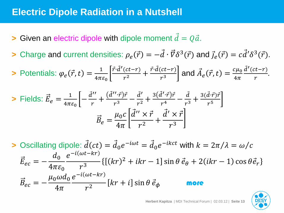
> Given an electric dipole with dipole moment 𝑑 = 𝑄.
> Charge and current densities: 𝜌𝑒 𝑟 = −𝑑 ∙ 𝛻𝛿3(𝑟) and 𝚥𝑒 𝑟 = 𝑐𝑑′𝛿3(𝑟).
> Potentials: 𝜑𝑒 𝑟, 𝑑 = 14𝜋𝜀0
𝑟∙′(𝑐𝜕−𝑟)𝑟2
+ 𝑟∙(𝑐𝜕−𝑟)𝑟3
and 𝐴𝑒 𝑟, 𝑑 = 𝑐𝜇04𝜋
′(𝑐𝜕−𝑟)𝑟
.
> Fields: 𝐸𝑒 = 14𝜋𝜀0
− ′′
𝑟+ ′′∙𝑟 𝑟
𝑟3− ′
𝑟2+ 3 ′∙𝑟 𝑟
𝑟4−
𝑟3+ 3(∙𝑟)𝑟
𝑟5
𝐵𝑒 =𝜇0𝑐4𝜋
𝑑′′ × 𝑟𝑟2
+𝑑′ × 𝑟𝑟3
> Oscillating dipole: 𝑑 𝑐𝑑 = 𝑑0𝑒−𝑖𝜔𝜕 = 𝑑0𝑒−𝑖𝑖𝑐𝜕 with 𝑘 = 2𝜋 𝜆⁄ = 𝜔 𝑐⁄
𝐸𝑒𝑐 = −𝑑0
4𝜋𝜀0𝑒−𝑖 𝜔𝜕−𝑖𝑟
𝑟3𝑘𝑟 2 + 𝑖𝑘𝑟 − 1 sin𝜃 𝑒𝜃 + 2 𝑖𝑘𝑟 − 1 cos𝜃𝑒𝑟
𝐵𝑒𝑐 = −𝜇0𝜔𝑑0
4𝜋𝑒−𝑖 𝜔𝜕−𝑖𝑟
𝑟2𝑘𝑟 + 𝑖 sin𝜃 𝑒𝜙 more
Herbert Kapitza | MDI Technical Forum | 02.03.12 | Seite 14
Magnetic Dipole Radiation in a Nutshell
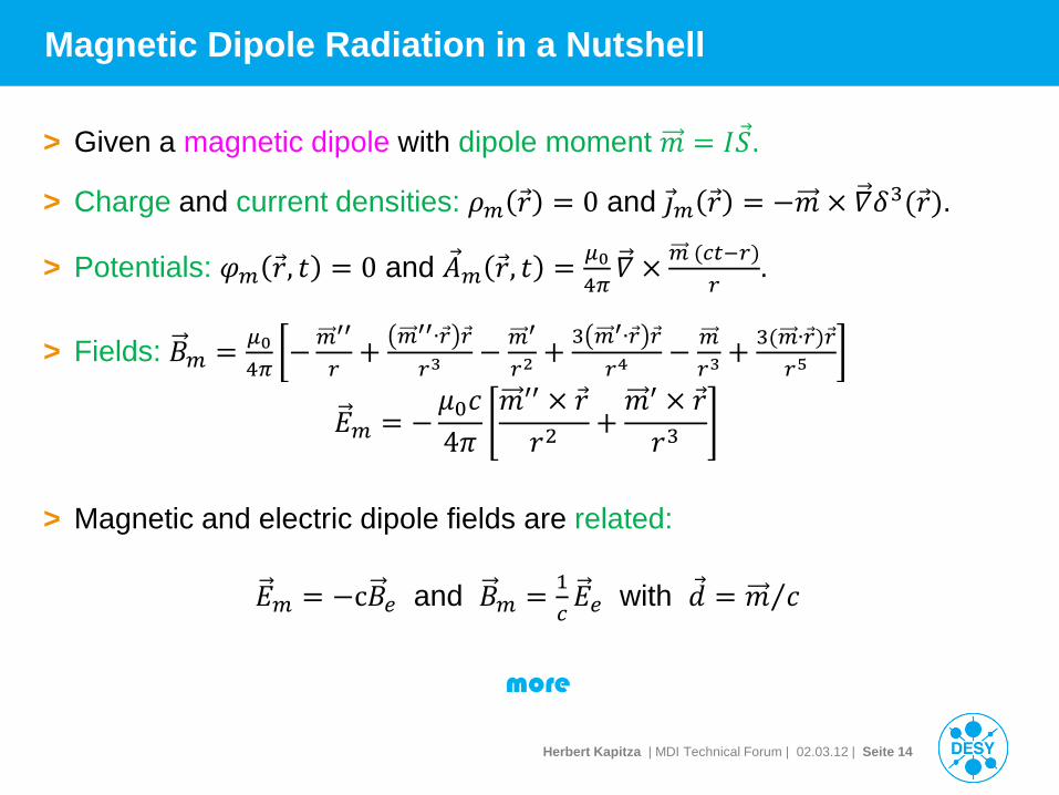
> Given a magnetic dipole with dipole moment 𝑚 = 𝐼𝑆.
> Charge and current densities: 𝜌𝑚 𝑟 = 0 and 𝚥𝑚 𝑟 = −𝑚 × 𝛻𝛿3(𝑟).
> Potentials: 𝜑𝑚 𝑟, 𝑑 = 0 and 𝐴𝑚 𝑟, 𝑑 = 𝜇04𝜋𝛻 × 𝑚 (𝑐𝜕−𝑟)
𝑟.
> Fields: 𝐵𝑚 = 𝜇04𝜋
−𝑚′′
𝑟+ 𝑚′′∙𝑟 𝑟
𝑟3− 𝑚′
𝑟2+ 3 𝑚′∙𝑟 𝑟
𝑟4− 𝑚
𝑟3+ 3(𝑚∙𝑟)𝑟
𝑟5
𝐸𝑚 = −𝜇0𝑐4𝜋
𝑚′′ × 𝑟𝑟2
+𝑚′ × 𝑟𝑟3
> Magnetic and electric dipole fields are related: 𝐸𝑚 = −c𝐵𝑒 and 𝐵𝑚 = 1
𝑐𝐸𝑒 with 𝑑 = 𝑚 𝑐⁄
more
Herbert Kapitza | MDI Technical Forum | 02.03.12 | Seite 15
EM Field Impedance
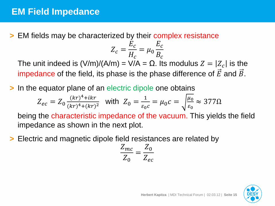
> EM fields may be characterized by their complex resistance
𝑍𝑐 =𝐸𝑐𝐻𝑐
= 𝜇0𝐸𝑐𝐵𝑐
The unit indeed is (V/m)/(A/m) = V/A = Ω. Its modulus 𝑍 = 𝑍𝑐 is the impedance of the field, its phase is the phase difference of 𝐸 and 𝐵.
> In the equator plane of an electric dipole one obtains
𝑍𝑒𝑐 = 𝑍0(𝑖𝑟)4+𝑖𝑖𝑟
(𝑖𝑟)4+(𝑖𝑟)2 with 𝑍0 = 1
𝜀0𝑐= 𝜇0𝑐 = 𝜇0
𝜀0≈ 377Ω
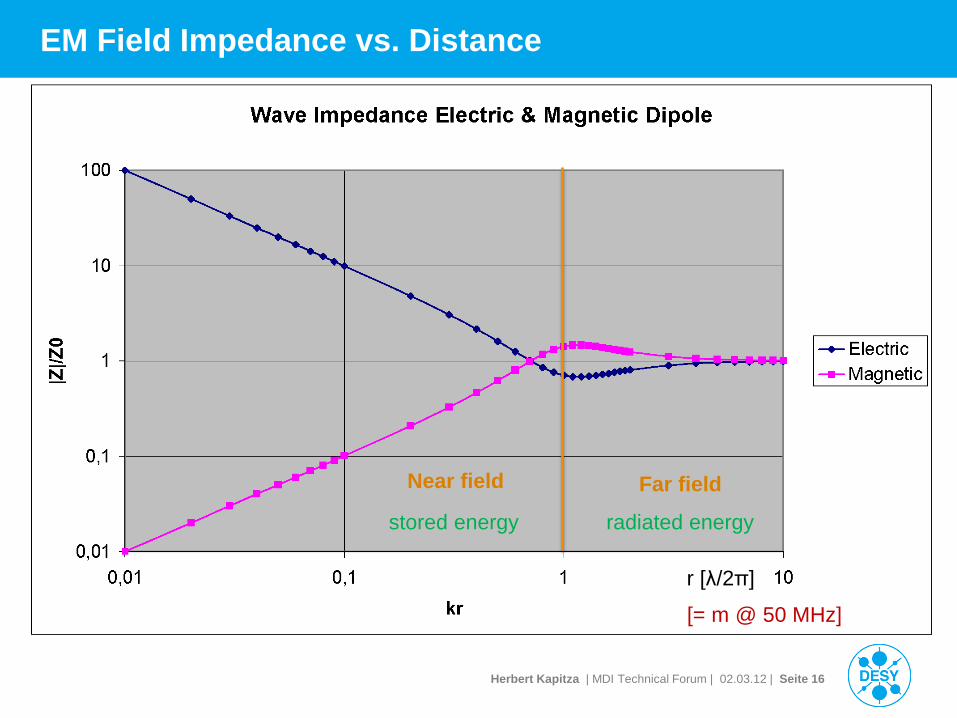
being the characteristic impedance of the vacuum. This yields the field impedance as shown in the next plot.
> Electric and magnetic dipole field resistances are related by 𝑍𝑚𝑐𝑍0
=𝑍0𝑍𝑒𝑐
Herbert Kapitza | MDI Technical Forum | 02.03.12 | Seite 16
EM Field Impedance vs. Distance
Far field Near field
stored energy radiated energy
r [λ/2π]
[= m @ 50 MHz]
Herbert Kapitza | MDI Technical Forum | 02.03.12 | Seite 17
EMI Couplings
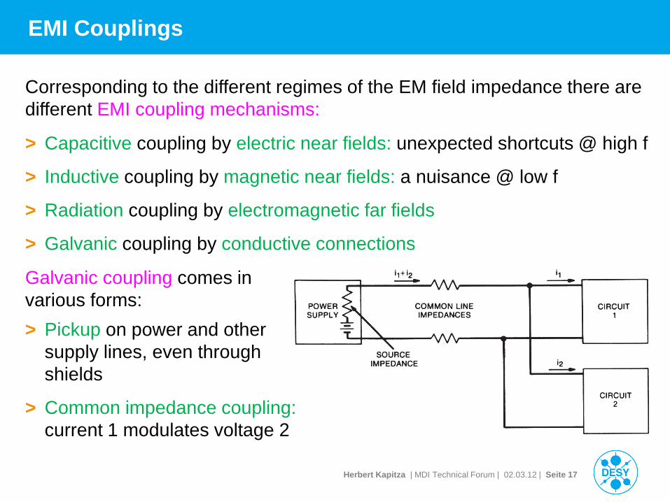
> Capacitive coupling by electric near fields: unexpected shortcuts @ high f
> Inductive coupling by magnetic near fields: a nuisance @ low f
> Radiation coupling by electromagnetic far fields
> Galvanic coupling by conductive connections
Corresponding to the different regimes of the EM field impedance there are different EMI coupling mechanisms:
Galvanic coupling comes in various forms: > Pickup on power and other
supply lines, even through shields
> Common impedance coupling: current 1 modulates voltage 2
Herbert Kapitza | MDI Technical Forum | 02.03.12 | Seite 18
Linear Networks and Circuit Analysis
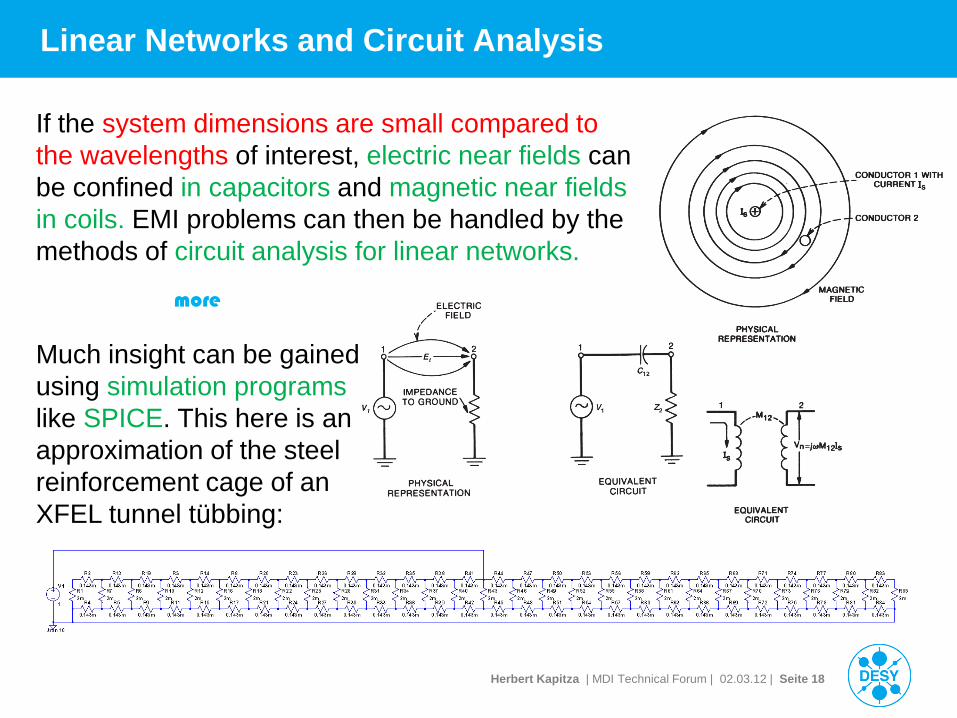
If the system dimensions are small compared to the wavelengths of interest, electric near fields can be confined in capacitors and magnetic near fields in coils. EMI problems can then be handled by the methods of circuit analysis for linear networks.
Much insight can be gained using simulation programs like SPICE. This here is an approximation of the steel reinforcement cage of an XFEL tunnel tübbing:
more

Herbert Kapitza | MDI Technical Forum | 02.03.12 | Seite 19
EMC Hardware Tools
> Since much EMI trouble stems from low f magnetic fields, it is important to know their sources, the currents. Rogowski coils are very useful here.
> A portable spectrum analyzer with several antennas is useful for quick overviews.
But we also used a DVB-T receiver on a laptop for some tests.
Herbert Kapitza | MDI Technical Forum | 02.03.12 | Seite 20
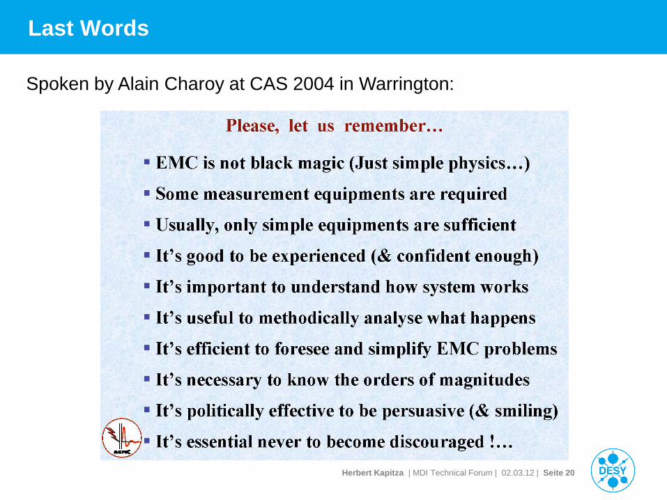
Last Words
Spoken by Alain Charoy at CAS 2004 in Warrington: