emergency master control-lslemcs - locksafelocksafe.com.au/wp-content/uploads/2013/07/... · the...
TRANSCRIPT

“The Master”The Emergency Master Control System
Mining - Marine - Transit – Solutions
Part Number- LSLEMCS
Distributed By:
Distributed By Locksafe Industrial Safety Equipment
1
The Emergency Master Control System
The MasterEmergency Master Control System
Part No - LSLEMCS
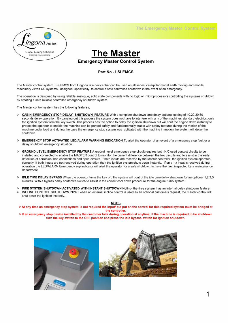
The Master control system LSLEMCS from Lingona is a device that can be used on all series caterpillar model earth moving and mobile
machinery 24volt DC systems , designed specifically to control a safe controlled shutdown in the event of an emergency.
The operation is designed by using reliable analogue, solid state components with no logic or microprocessors controlling the systems shutdown
by creating a safe reliable controlled emergency shutdown system.
The Master control system has the following features;
� CABIN EMERGENCY STOP DELAY SHUTDOWN FEATURE With a complete shutdown time delay optional setting of 10,20,30,60
seconds delay operation. By carrying out this process the system does not have to interfere with any of the machines standard electrics, only
the ignition system from the key switch. This process has the option to delay the ignition shutdown but will shut the engine down instantly to
protect the operator to enable the machine can be parked safely and fundamentally stable with safety features during the motion of the
machine under load and during the case the emergency stop system was activated with the machine in motion the system will delay the
shutdown.
� EMERGENCY STOP ACTIVATED LED/ALARM WARNING INDICATION To alert the operator of an event of a emergency stop fault or a
delay shutdown emergency situation.
� GROUND LEVEL EMERGENCY STOP FEATURE A ground level emergency stop circuit requires both N/Closed contact circuits to be
installed and connected to enable the MASTER control to monitor the current difference between the two circuits and to assist in the early
detection of corrosion/ bad connections and open circuits. If both inputs are received by the Master controller, the ignition system operates
correctly, If both inputs are not received during operation than the ignition system shuts down instantly. If only 1 x input is received during
operation the LED/ALARM Emergency sop indicator will alert the operator for a safe shutdown to have the fault inspected by a maintenance
department.
� IDLE TIME DELAY BYPASS When the operator turns the key off, the system will control the idle time delay shutdown for an optional 1,2,3,5
minutes. With a bypass delay shutdown switch to assist in the correct cool down procedure for the engine turbo system.
� FIRE SYSTEM SHUTDOWN ACTIVATED WITH INSTANT SHUTDOWN Noting- the fires system has an internal delay shutdown feature.
� INCLINE CONTROL SHUTDOWN INPUT when an external incline control is used as an optional customers request, the master control will
shut down the ignition instantly.
NOTE-
> At any time an emergency stop system is not required the input/ out put on the control for this required system must be bridged at
the controller.
> If an emergency stop device installed by the customer fails during operation at anytime, if the machine is required to be shutdown
turn the key switch to the OFF position and press the idle bypass switch for ignition shutdown.

The Emergency Master Control System
The MasterEmergency Master Control System Circuit Board Layout
� LED indicator locations on the RHS for troubleshooting
� The idle time and Emergency delay shutdown DIP switches on the LHS
3
Grey Plug
Black Plug
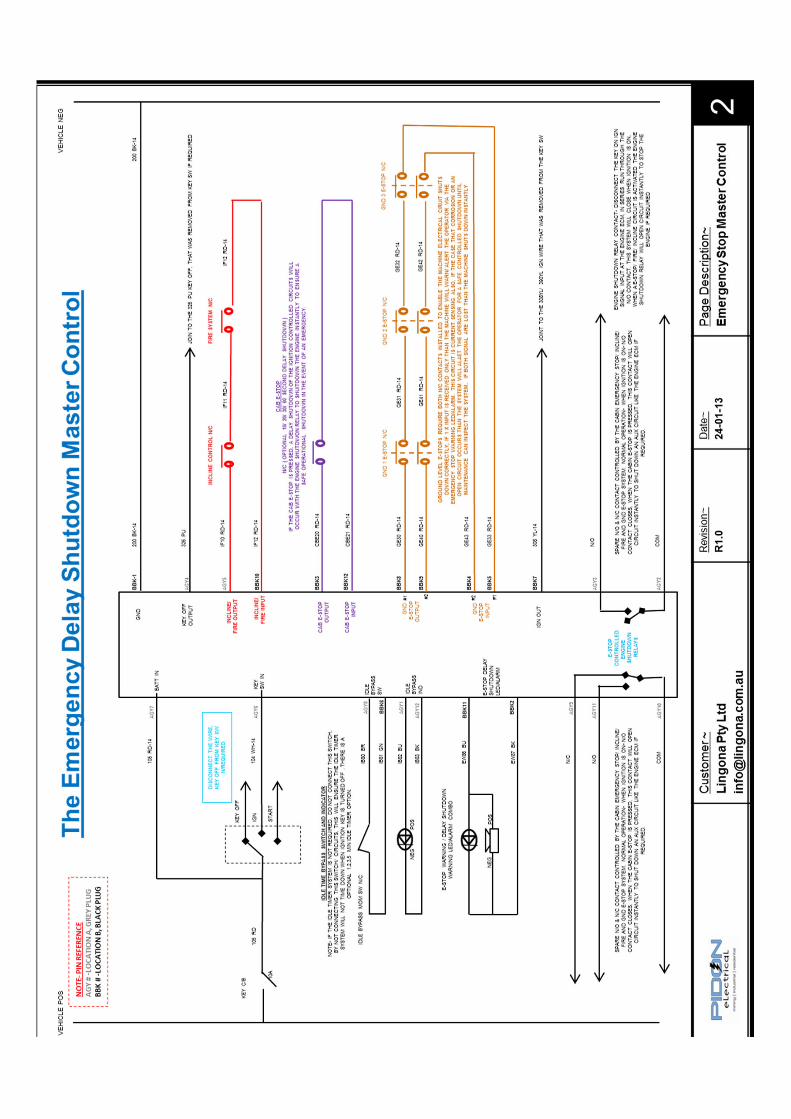
Termination Requirements
The Emergency Master Control system requires 2 x 12 pin deutsch plugs which are supplied with the installation kit, referring to the electrical
schematic for correct installation connection pin locations.
4
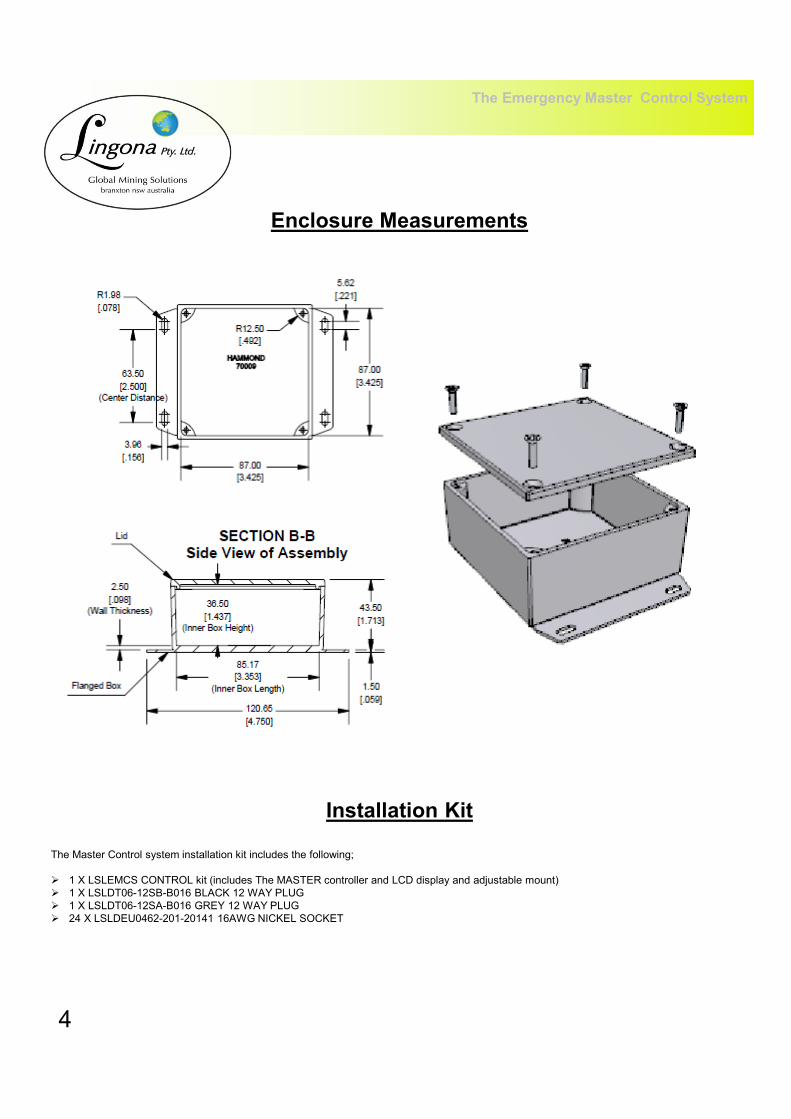
Installation Kit
The Master Control system installation kit includes the following;
� 1 X LSLEMCS CONTROL kit (includes The MASTER controller and LCD display and adjustable mount)
� 1 X LSLDT06-12SB-B016 BLACK 12 WAY PLUG
� 1 X LSLDT06-12SA-B016 GREY 12 WAY PLUG
� 24 X LSLDEU0462-201-20141 16AWG NICKEL SOCKET
The Emergency Master Control System
Enclosure Measurements

2010
www.lingona.com.au
Distributed By Locksafe Industrial Safety Equipment