emerge 50p emerge 5000p hardware installation guide 50p emerge 5000p . hardware installation guide ....
TRANSCRIPT

eMerge 50P eMerge 5000P
Hardware Installation Guide
May 2013
Linear LLC 1950 Camino Vida Roble
Suite 150 Carlsbad, CA 92008 www.linearcorp.com

233190 X3 Linear LLC ii May 2013
Copyright © Linear LLC. All rights reserved. This guide is protected by copyright and all rights are reserved by Linear LLC. It may not, in whole or in part, except insofar as herein directed, be copied, photocopied, reproduced, translated or reduced to any electronic medium or machine-readable form without prior written consent of Linear LLC. eMerge™ is a registered trademark of Linear LLC.

233190 X3 Linear LLC iii May 2013
Contents
Introduction ........................................................................................................................................... 1 Where to Go for More Information .................................................................................................. 1 Installation Notes .............................................................................................................................. 2
Preparing to Install ............................................................................................................................... 3 eMerge System Overview ................................................................................................................ 3 Topology Considerations.................................................................................................................. 3 System Requirements ....................................................................................................................... 5
Network Requirements .............................................................................................................. 5 Browser Requirements ............................................................................................................... 5 Power Requirements .................................................................................................................. 5 Environmental Requirements ..................................................................................................... 6 Static Electricity Precautions ..................................................................................................... 6
Installation Overview Checklist ....................................................................................................... 7 eMerge Part Numbers ....................................................................................................................... 7
Mounting the Cabinet ........................................................................................................................... 8
Installing Additional Blades ................................................................................................................. 9 How Slot and Position Numbers are Determined ............................................................................. 9
Connecting Readers, Inputs, Outputs, and Temperature Sensors ................................................. 12 Wiring Readers ............................................................................................................................... 12 Connecting Readers ........................................................................................................................ 13 Wiring Inputs .................................................................................................................................. 14 Connecting Inputs ........................................................................................................................... 15 Input Supervision Types ................................................................................................................. 16
Normally Closed Parallel Resistor Input Circuits .................................................................... 17 Normally Closed Series Resistor Input Circuits ...................................................................... 17 Normally Closed Unsupervised Input Circuits ........................................................................ 18 Normally Open Parallel Resistor Input Circuits ...................................................................... 18 Normally Open Series Resistor Input Circuits ......................................................................... 19 Normally Open Unsupervised Input Circuits ........................................................................... 19
Wiring Outputs ............................................................................................................................... 20 Connecting Outputs ........................................................................................................................ 22 Wiring Temperature Sensors .......................................................................................................... 23 Connecting Temperature Sensors ................................................................................................... 25
Wiring the Network Connection ........................................................................................................ 26
Wiring Power ...................................................................................................................................... 27 Wiring the PIP ................................................................................................................................ 27 Wiring a DC Power Source ............................................................................................................ 27
Adding a Backup Battery ................................................................................................................... 29
Setting Up a Small Configuration Network ...................................................................................... 30
Testing and Troubleshooting ............................................................................................................. 32 The Mini-ITX Network Controller ................................................................................................. 32 Interpreting the System Status LED on the Cabinet Door .............................................................. 33

Contents
233190 X3 Linear LLC iv May 2013
Interpreting Beeps ......................................................................................................................... 33 The Access Control Blade .............................................................................................................. 34 Input, Output, and Temperature Blades ......................................................................................... 34
Interpreting Access Control, Input, Output, and Temperature Blade LEDs ............................ 35 Removing Blades ........................................................................................................................... 35 Using the Power, Reset, and Revert Buttons on the eMerge50/5000P .......................................... 36
Hardware and Third-Party Device Specifications ........................................................................... 39 Environmental Requirements ......................................................................................................... 39 Power Requirements ....................................................................................................................... 39 Reader Power Available from the eMerge System ........................................................................ 39 Wiring Requirements and Specifications ....................................................................................... 39 Readers ........................................................................................................................................... 40 Cameras .......................................................................................................................................... 40 Temperature Sensors ...................................................................................................................... 41 Software Protocols and Standards .................................................................................................. 41 Single Facility Maximum Capacities ............................................................................................. 41 Minimum System Configuration .................................................................................................... 41
Index ..................................................................................................................................................... 42

233190 X3 Linear LLC 1 May 2013
Introduction
This guide describes the hardware installation for a Linear eMerge system. It includes:
• A system overview and topology considerations (page 3), and system requirements (page 5).
• Instructions for mounting the cabinet (page 8).
• Instructions for adding any required additional blades (page 9).
• Instructions for connecting readers, inputs, outputs, and temperature sensors (page 12).
• Instructions for wiring the network connection (page 26).
• Instructions for wiring power (page 27).
• Instructions for adding a backup battery (page 29).
• Instructions for setting up a small network, if necessary, which can be used to complete the initial software setup before the system is connected to the corporate network (page 30).
• Testing and troubleshooting information (page 32).
• Information on interpreting the various system LED states and beeps (page 32).
• Hardware and third-party device specifications (page 39).
Note: Check the Linear web site (www.linearcorp.com) for updated specifications, lists of supported devices, and software updates.
Where to Go for More Information When the hardware installation is complete, refer to the following publications:
• The “Initial Software Setup Guide” for information on setting initial IP values and logging into the security application.
• The “Network Node Hardware Installation Guide” for information on installing additional Network Nodes and application extension blades.

Introduction
233190 X3 Linear LLC 2 May 2013
Installation Notes
Note to Installers
Install according to ANSI/NFPA70 and local codes and use only UL Listed equipment.
CAUTION
OBSERVE STATIC ELECTRICITY PRECAUTIONS WHEN HANDLING AND INSTALLING SYSTEM COMPONENTS. THESE COMPONENTS CAN BE DAMAGED BY STATIC DISCHARGE.
Disclaimer
Linear LLC provides this publication “as is,” without warranty of any kind, either expressed or implied. Linear LLC shall not be liable for errors contained herein or for incidental or consequential damages in connection with the furnishing, performance, or use of this guide.

233190 X3 Linear LLC 3 May 2013
Preparing to Install
eMerge System Overview eMerge is a web-based system that does not require a computer to operate. A computer is required only for system setup, programming, and monitoring.
eMerge is provided in a controller cabinet containing the following:
• A Mini-ITX Network Controller running the controller application software.
• A SAM-E module providing network connectors and power buttons.
• A Network Node blade running the node application software.
• An access control blade that supports up to two card readers. You can add up to three additional application extension blades to the cabinet. For more information, see “Connecting Readers, Inputs, Outputs, and Temperature Sensors” on page 12.
Note: The cabinet for the supported eMerge expansion node is the same except that it does not contain a Mini-ITX Network Controller.
Topology Considerations Issues to consider when selecting a topology for the installation include simplicity, security, wiring requirements, bandwidth requirements, site distances, current network topology, and the number of security system resources to be wired.
The simplest topology, shown in Figure 1, will be the most common case for small systems. All users and network resources share the same LAN.

Preparing to Install
233190 X3 Linear LLC 4 May 2013
Figure 1. The simplest topology for a eMerge installation. (Not Evaluated
by UL)
This topology shown in Figure 2 is somewhat more complicated, but it is inherently more secure.
Figure 2. A more secure topology that includes a VLAN. (Not Evaluated
by UL)

Preparing to Install
233190 X3 Linear LLC 5 May 2013
In this case, a security VLAN is used to create a subnet for the security system. As a result, the corporate LAN does not directly carry traffic between the Nodes and the Controller.
The advantages to this topology are increased network security and decreased bandwidth requirements. The disadvantages include potentially increased wiring, and greater complexity.
System Requirements
Network Requirements
The application is designed to work with Ethernet networks using TCP/IP. Although it will operate on 10baseT networks, 100baseT is preferred. A 100baseT network may be required for good performance if IP cameras and/or digital video are used.
Note: Networking is not evaluated by UL, only standalone systems.
Before beginning the installation, obtain the following information from the customer’s network administrator.
Static IP addresses for the blade running combination Controller application software, and for each blade running node-only application software.
Subnet mask for the controller and nodes.
Gateway IP address.
DNS (Domain Name Server) IP address(es), if any.
Browser Requirements
The application is designed to work with the following web browsers:
• Microsoft Internet Explorer Versions 8 and 9 (recommended)
• Mozilla Firefox Versions 10 and 11
• Apple Safari Version 5
Power Requirements
• DC power is provided via a Listed UL 603 power-limited supply and must have 12V± 1% DC at a minimum of 5 amps. Source power must come from a separate circuit with its own breaker and an isolated earth ground.

Preparing to Install
233190 X3 Linear LLC 6 May 2013
Environmental Requirements
• Operating temperature range: 32° F to 120° F (0° C to 49° C).
• Operating relative humidity range: Up to 85% non-condensing.
Static Electricity Precautions
The system components can be damaged by static discharge. Observe the following precautions when handling and installing these components:
• Discharge by touching a ground before handling components.
• Wear a grounded wrist strap or stand on a grounded mat.
• Limit movement to limit static buildup.

Preparing to Install
233190 X3 Linear LLC 7 May 2013
Installation Overview Checklist The major steps required for installing an eMerge system are as follows:
Review the information in this section to prepare for the installation.
Mount the cabinet (page 8).
Install any required additional blades (page 9).
Connect readers, inputs, outputs, and temperature sensors (page 12).
Wire the network connection (page 26).
Connect the system to a power source (page 12).
Add a backup battery (page 29).
Set up a small configuration network, if necessary (page 30).
This checklist presents a logical sequence for completing the installation. Although it is not necessary to perform the steps in exactly this order, everything should be plugged in BEFORE powering the unit.
CAUTION: Observe static electricity precautions when handling and installing system components. These components can be damaged by static discharge.
eMerge Part Numbers Network Node Blade 0-587009
Access Control Blade 0-580100-L
Input Blade 0-580110
Output Blade 0-580120
Temperature Blade 0-580130
eMerge50P 230219P
eMerge5000P 230220P
Expansion Node 0-587004
233190 X3 Linear LLC 8 May 2013
Mounting the Cabinet
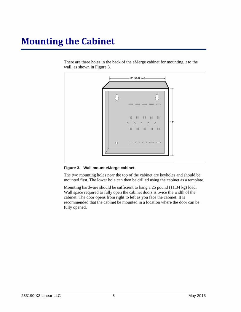
There are three holes in the back of the eMerge cabinet for mounting it to the wall, as shown in Figure 3.
Figure 3. Wall mount eMerge cabinet.
The two mounting holes near the top of the cabinet are keyholes and should be mounted first. The lower hole can then be drilled using the cabinet as a template.
Mounting hardware should be sufficient to hang a 25 pound (11.34 kg) load. Wall space required to fully open the cabinet doors is twice the width of the cabinet. The door opens from right to left as you face the cabinet. It is recommended that the cabinet be mounted in a location where the door can be fully opened.

233190 X3 Linear LLC 9 May 2013
Installing Additional Blades
The eMerge cabinet has five slots in the aluminum chassis. The leftmost slot is reserved for the Network Node blade running the node application software. The access control blade provided is mounted to its right, in slot 1.
The remaining slots, numbered 2 through 4, can hold any combination of access control, input, output, and temperature application extension blades.
Figure 4. Slots for installing application extension blades.
You can use the slots in any sequence you choose. Note that the slots are physical mounting points only. The electrical connection is made through the ribbon cable, shown in Figure 5 on page 10.
How Slot and Position Numbers are Determined Regardless of the physical slot in which a blade is mounted, its slot number is determined by the ribbon-cable connector you plug into the blade. This is because the ribbon cable (shown in Figure 5) is a bus, and a blade’s position on the bus determines its slot number.
For example, even if a blade is mounted in physical slot 3, if it is attached to ribbon cable connector 4, the application will see it in slot 4 on the bus.
Installing Additional Blades
233190 X3 Linear LLC 10 May 2013
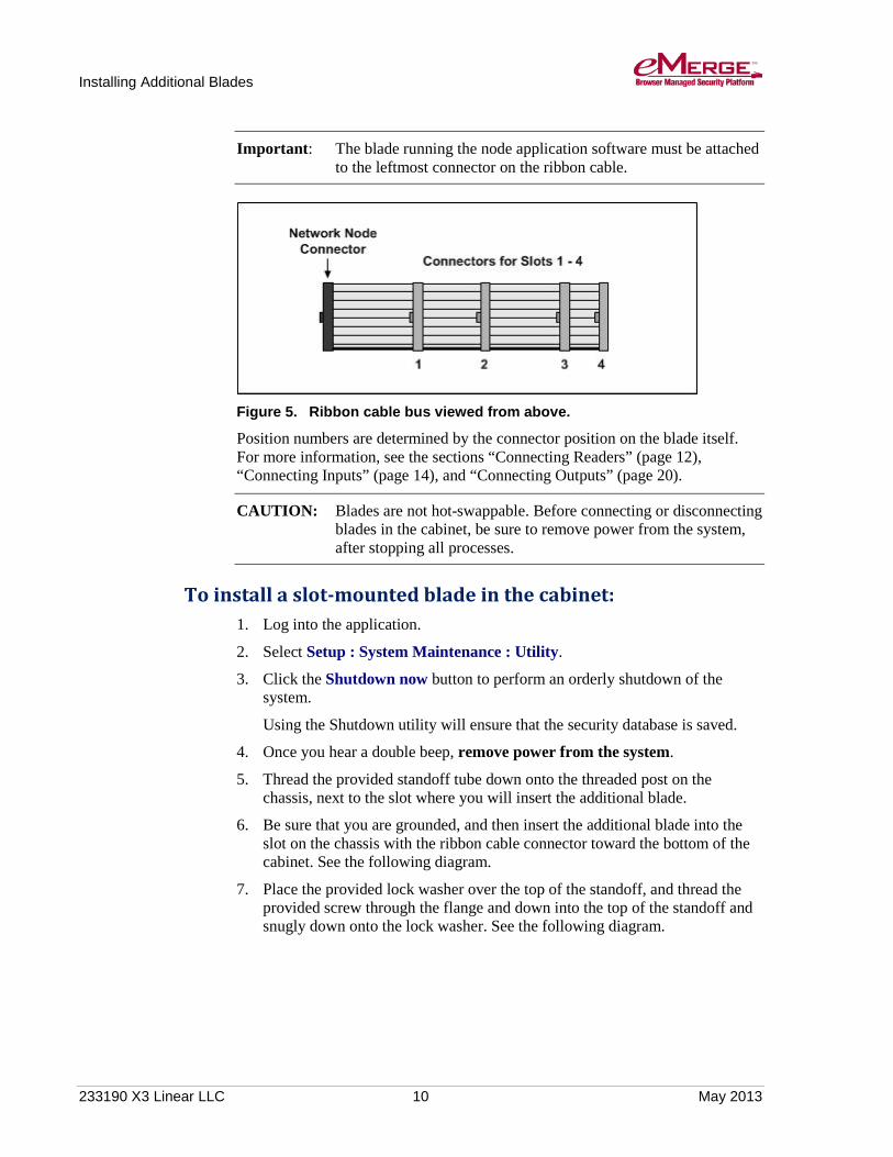
Important: The blade running the node application software must be attached to the leftmost connector on the ribbon cable.
Figure 5. Ribbon cable bus viewed from above.
Position numbers are determined by the connector position on the blade itself. For more information, see the sections “Connecting Readers” (page 12), “Connecting Inputs” (page 14), and “Connecting Outputs” (page 20).
CAUTION: Blades are not hot-swappable. Before connecting or disconnecting blades in the cabinet, be sure to remove power from the system, after stopping all processes.
To install a slot-mounted blade in the cabinet: 1. Log into the application.
2. Select Setup : System Maintenance : Utility.
3. Click the Shutdown now button to perform an orderly shutdown of the system.
Using the Shutdown utility will ensure that the security database is saved.
4. Once you hear a double beep, remove power from the system.
5. Thread the provided standoff tube down onto the threaded post on the chassis, next to the slot where you will insert the additional blade.
6. Be sure that you are grounded, and then insert the additional blade into the slot on the chassis with the ribbon cable connector toward the bottom of the cabinet. See the following diagram.
7. Place the provided lock washer over the top of the standoff, and thread the provided screw through the flange and down into the top of the standoff and snugly down onto the lock washer. See the following diagram.

Installing Additional Blades
233190 X3 Linear LLC 11 May 2013
Figure 6. Installing a slot-mounted blade.
8. Connect the ribbon cable from the blade in the leftmost slot to the newly installed blade.
The connector is polarized. Make sure that the center bump fits into the opening for it on the connector located on the blade.
9. Press the connector firmly into place until you hear the click of the extraction levers snapping into vertical position. You may have to press the extraction levers into full vertical position before you will hear the click.

233190 X3 Linear LLC 12 May 2013
Connecting Readers, Inputs, Outputs, and Temperature Sensors
Each eMerge supports up to four application extension blades in any combination. There are four types of application extension blades:
• Access control blade: Includes two Wiegand reader interfaces, four supervised inputs, and four relay outputs. (6V / 70mA) o An access control blade is included in the cabinet. o An access control blade is compatible with UL listed 26 bit, 128 bit, and
200 bit Wiegand readers.
• Input blade: Includes eight supervised inputs. (6V / 60mA)
• Output blade: Includes eight relay outputs. (6V / 55mA)
• Temperature blade: Includes eight temperature input points. (Not UL listed.) You can easily add application blades to your system in the future by following the steps on page 10.
This section describes how to connect readers, inputs, outputs, and temperature sensors.
Wiring Readers
CAUTION: Make sure all power is removed from the Network Node prior to wiring and/or connecting any reader to a blade.
To wire readers: 1. Log into the application.
2. Select Setup : System Maintenance : Utility.
3. Click the Shutdown now button to perform an orderly shutdown of the system.
Using the Shutdown utility will ensure that the security database is saved.
4. Once you hear a double beep, remove power from the system.
Note: Steps 1-4 apply only to cabinets containing both a Mini-ITX Network Controller and a Network Node. Expansion Node cabinets simply require that you remove power before connecting any reader.
5. Be sure that you are grounded, and then pull the wiring through a knockout in the cabinet.

Connecting Readers, Inputs, Outputs, and Temperature Sensors
233190 X3 Linear LLC 13 May 2013
Wire specification: Twisted, shielded 22 AWG Belden #9536 (6 conductor) or equivalent. Maximum distance: 500 feet (152 meters).
6. Connect the reader wires to the 7-pin reader connector provided, as shown in the following diagram.
Figure 7. The 7-pin reader connector.
Note: Refer to the documentation provided by the reader manufacturer for LEDs and Bpr (Beeper) wire colors.
7. Be sure there is no power to the system.
8. Plug the connector into a reader position on the access control blade.
Connecting Readers
CAUTION: Make sure all power is off before connecting any reader to a blade.
Access control blades have two, 7-pin reader connectors mounted on the blade, as shown in the following figure.
Figure 8. The two 7-pin reader connections on the access control blade.
Bpr
Grn LED controlRed LED controlD1
(white)D0
(green)Gnd
(black)
Pwr(red)

Connecting Readers, Inputs, Outputs, and Temperature Sensors
233190 X3 Linear LLC 14 May 2013
Note: Each access control blade provides a maximum of 400mA peak power to the readers, 1 x 400mA or 2 x 200mA per board (1.6A maximum is supplied). If the reader(s) connected to the access control blade draw more than 400mA, external power must be supplied to these readers by a UL603 Power Limited Supply .
The access control blade will not function properly if the reader(s) draw more than 400mA peak.
The color-coded wires from the reader wiring harness must be connected to the 7-pin connector. The color-coding for Power (red), Ground (black), Data 0 (green), and Data 1 (white) is Security Industry Association (SIA) standard.
• Reader Beeper control: This varies by manufacturer and model. Refer to the documentation provided by the reader manufacturer for details on your particular reader. Typically, the reader will beep for the duration of a momentary unlock, or until the door is opened. This occurs whether the door is unlocked by a valid card read or from the application. If no beeper is desired, do not connect the beeper control wire.
• Reader LED control: This varies by manufacturer and model. Some use two-wire LED control and some use one-wire control. Refer to the documentation provided by the reader manufacturer for details on your particular reader. Control involving signal pulsing to change LED color is not supported.
The access control blade has both red and green LED control connections. The 7-pin reader connector wiring is shown in Figure 7 on page 13.
Note: LED display behavior for your particular reader may vary. Refer to the reader manufacturer documentation.
Wiring Inputs Inputs are dry contact only. An input looks for a change in resistance, not a change in voltage.
CAUTION: Make sure all power is removed from the Network Node prior to wiring and/or connecting any input to a blade.
To wire inputs: 1. Log into the application.
2. Select Setup : System Maintenance : Utility.
3. Click the Shutdown now button to perform an orderly shutdown of the system.
Using the Shutdown utility will ensure that the security database is saved.
4. Once you hear a double beep, remove power from the system.

Connecting Readers, Inputs, Outputs, and Temperature Sensors
233190 X3 Linear LLC 15 May 2013
Note: Steps 1-4 apply only to cabinets containing both a Mini-ITX Network Controller and a Network Node blade. Expansion Node cabinets simply require that you remove power before connecting any input.
5. Be sure that you are grounded, and then pull the wiring through a knockout in the cabinet.
Wire specification: Twisted, shielded 22 AWG Belden #9462 or equivalent. Maximum distance: 2000 feet (610 meters).
6. Connect the input wires to the 2-pin input connector provided.
7. Be sure there is no power to the system.
8. Plug the connector into an input position on an access control blade or input blade. These connectors are polarized and can only be inserted one way.
9. If you are connecting previously wired or previously installed inputs, determine the input supervision type: normally open (NO) or normally closed (NC); zero, one, or two resistors; or single resistors in parallel or series.
You will need this information for the software setup of the input. See the section, “Input Supervision Types” on page 16.
Note: The system supports the use of 1k Ohm resistors only.
10. If you are installing the input device, refer to the input device manual to determine if the device circuit is normally open (NO) or normally closed (NC).
11. Select the input supervision type you want, then install the supervision resistor(s) at the end of the input line.
Connecting Inputs
CAUTION: Make sure all power is off before connecting inputs to blades.
Inputs can be connected either to an access control blade or to an input blade.
Access control blades have four male, 2-pin input connectors mounted on the blade as shown in Figure 9.
Figure 9. Input connectors mounted on the access control blade.
Ribbon cable connector
2-pin inputs
1 2 3 4 positions
Connecting Readers, Inputs, Outputs, and Temperature Sensors
233190 X3 Linear LLC 16 May 2013
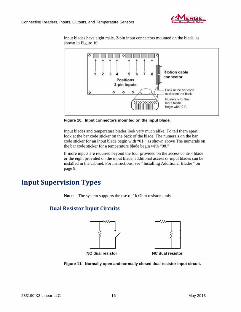
Input blades have eight male, 2-pin input connectors mounted on the blade, as shown in Figure 10.
Figure 10. Input connectors mounted on the input blade.
Input blades and temperature blades look very much alike. To tell them apart, look at the bar code sticker on the back of the blade. The numerals on the bar code sticker for an input blade begin with “01,” as shown above The numerals on the bar code sticker for a temperature blade begin with “08.”
If more inputs are required beyond the four provided on the access control blade or the eight provided on the input blade, additional access or input blades can be installed in the cabinet. For instructions, see “Installing Additional Blades” on page 9.
Input Supervision Types
Note: The system supports the use of 1k Ohm resistors only.
Dual Resistor Input Circuits
Figure 11. Normally open and normally closed dual resistor input circuit.
NO dual resistor NC dual resistor
Connecting Readers, Inputs, Outputs, and Temperature Sensors
233190 X3 Linear LLC 17 May 2013
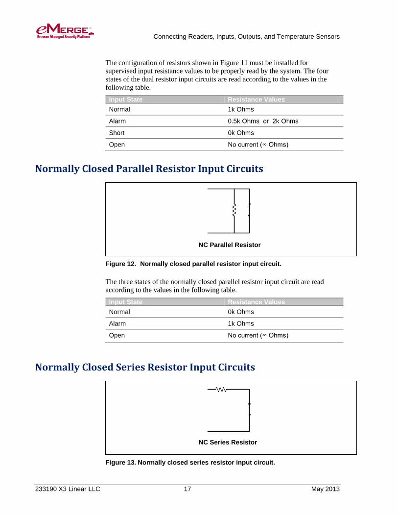
The configuration of resistors shown in Figure 11 must be installed for supervised input resistance values to be properly read by the system. The four states of the dual resistor input circuits are read according to the values in the following table.
Input State Resistance Values Normal 1k Ohms
Alarm 0.5k Ohms or 2k Ohms
Short 0k Ohms
Open No current (∞ Ohms)
Normally Closed Parallel Resistor Input Circuits
Figure 12. Normally closed parallel resistor input circuit.
The three states of the normally closed parallel resistor input circuit are read according to the values in the following table.
Input State Resistance Values Normal 0k Ohms
Alarm 1k Ohms
Open No current (∞ Ohms)
Normally Closed Series Resistor Input Circuits
Figure 13. Normally closed series resistor input circuit.
NC Series Resistor
NC Parallel Resistor
Connecting Readers, Inputs, Outputs, and Temperature Sensors
233190 X3 Linear LLC 18 May 2013
The three states of the normally closed series resistor input circuit are read according to the values in the following table.
Input State Resistance Values Normal 1k Ohms
Alarm No current (∞ Ohms)
Short 0k Ohms
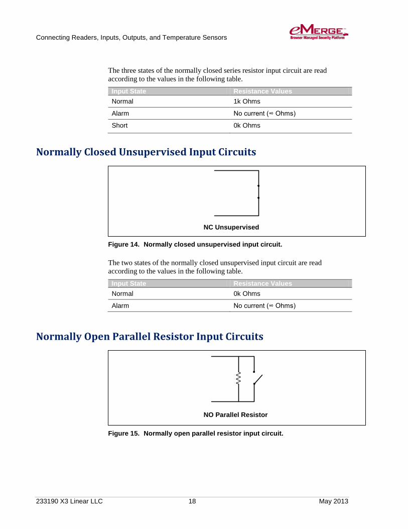
Normally Closed Unsupervised Input Circuits
Figure 14. Normally closed unsupervised input circuit.
The two states of the normally closed unsupervised input circuit are read according to the values in the following table.
Input State Resistance Values Normal 0k Ohms
Alarm No current (∞ Ohms)
Normally Open Parallel Resistor Input Circuits
Figure 15. Normally open parallel resistor input circuit.
NO Parallel Resistor
NC Unsupervised

Connecting Readers, Inputs, Outputs, and Temperature Sensors
233190 X3 Linear LLC 19 May 2013
The three states of the normally open parallel resistor input circuit are read according to the values in the table below.
Input State Resistance Values Normal 1k Ohms
Alarm 0k Ohms
Open No current (∞ Ohms)
Normally Open Series Resistor Input Circuits
Figure 16. Normally open series resistor input circuit.
The three states of the normally open series resistor input circuit are read according to the values in the following table.
Input State Resistance Values Normal No current (∞ Ohms)
Alarm 1k Ohms
Short 0k Ohms
Normally Open Unsupervised Input Circuits
Figure 17. Normally open unsupervised input circuit.
NO Unsupervised
NO Series Resistor

Connecting Readers, Inputs, Outputs, and Temperature Sensors
233190 X3 Linear LLC 20 May 2013
The two states of the normally open unsupervised input circuit are read according to the values in the following table.
Input State Resistance Values Normal No current (∞ Ohms)
Alarm 0k Ohms
Wiring Outputs
CAUTION: Make sure all power is off before wiring and connecting outputs.
To wire outputs: 1. Log into the application.
2. Select Setup : System Maintenance : Utility.
3. Click the Shutdown now button to perform an orderly shutdown of the system.
Using the Shutdown utility will ensure that the security database is saved.
4. Once you hear a double beep, remove power from the system.
Note: Steps 1-4 apply only to cabinets containing both a Mini-ITX Network Controller and a Network Node blade. Expansion Node cabinets simply require that you remove power before connecting any output.
5. Be sure that you are grounded, and then pull the wiring through a knockout in the cabinet.
Wire specification: Twisted, shielded 22 AWG Belden #9462 or equivalent. Maximum distance: 2000 feet (610 meters).
6. Refer to the output device manual to determine if the device is normally energized or normally not energized, and if it is DC or AC powered.
7. Connect the output wiring to the 3-pin output connector Pin 1 is normally closed (NC). Pin 2 is common. Pin 3 is normally open (NO).
8. Be sure there is no power to the system.
9. Plug the connector into an output position on an access control blade or an output blade. These connectors are polarized and can only be inserted one way.
Connecting Readers, Inputs, Outputs, and Temperature Sensors
233190 X3 Linear LLC 21 May 2013
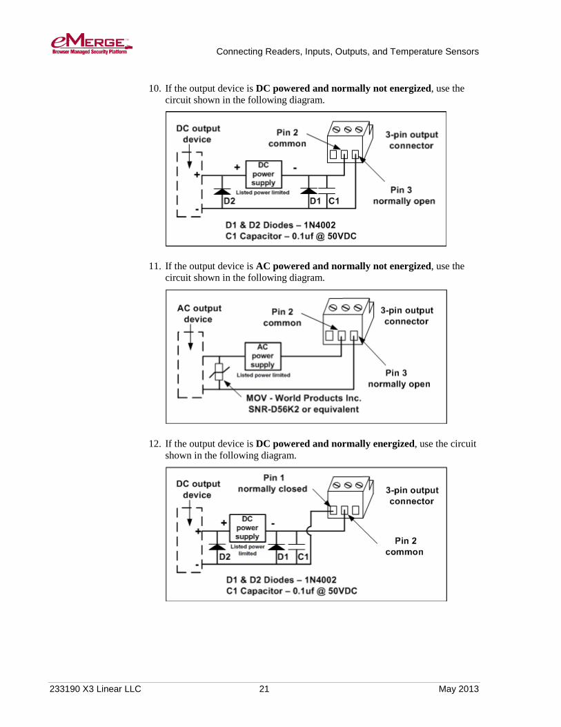
10. If the output device is DC powered and normally not energized, use the circuit shown in the following diagram.
11. If the output device is AC powered and normally not energized, use the circuit shown in the following diagram.
12. If the output device is DC powered and normally energized, use the circuit shown in the following diagram.
Connecting Readers, Inputs, Outputs, and Temperature Sensors
233190 X3 Linear LLC 22 May 2013
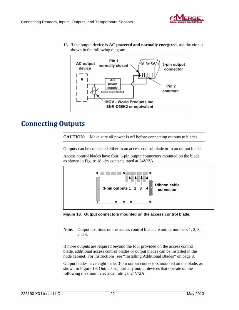
13. If the output device is AC powered and normally energized, use the circuit shown in the following diagram.
Connecting Outputs
CAUTION: Make sure all power is off before connecting outputs to blades.
Outputs can be connected either to an access control blade or to an output blade.
Access control blades have four, 3-pin output connectors mounted on the blade as shown in Figure 18, dry contacts rated at 24V/2A.
Figure 18. Output connectors mounted on the access control blade.
Note: Output positions on the access control blade are output numbers 1, 2, 3, and 4.
If more outputs are required beyond the four provided on the access control blade, additional access control blades or output blades can be installed in the node cabinet. For instructions, see “Installing Additional Blades” on page 9.
Output blades have eight male, 3-pin output connectors mounted on the blade, as shown in Figure 19. Outputs support any output devices that operate on the following maximum electrical ratings: 24V/2A.
Ribbon cable connector3-pin outputs 1 2 3 4

Connecting Readers, Inputs, Outputs, and Temperature Sensors
233190 X3 Linear LLC 23 May 2013
Figure 19. The output blade.
CAUTION: The diodes and varistors shown in the diagrams that follow must be installed as indicated. They are designed to protect the output circuits from induced voltage spikes, which can damage the output circuitry on the blade.
Wiring Temperature Sensors
CAUTION: Make sure all power is off before wiring and connecting temperature sensors.
Wiring temperature sensors are not investigated by UL.
To wire temperature sensors: 1. Log into the application.
2. Select Setup : System Maintenance : Utility.
3. Click the Shutdown now button to perform an orderly shutdown of the system.
Using the Shutdown utility will ensure that the security database is saved.
4. Once you hear a double beep, remove power from the system.

Connecting Readers, Inputs, Outputs, and Temperature Sensors
233190 X3 Linear LLC 24 May 2013
Note: Steps 1-4 apply only to cabinets containing both a Mini-ITX Network Controller board and a Network Node blade. Expansion Node cabinets simply require that you remove power before connecting any temperature sensor.
5. The cable lead from the white temperature sensor wire must connect to pin one, and the cable lead from the black temperature sensor wire must connect to pin two, of the temperature input connector. See the following diagram.
Note: For distances up to 500 feet (152.4 meters), use Category 3 cable. For distances over 500 feet up to 1000 feet (304.8 meters), use Category 5 cable.
6. Be sure that you are grounded.
7. Pull the cable through a knockout in the cabinet. Connect the 2-pin temperature input connector to the temperature blade.
Black wire to pin 2
White wire to pin 1
2-pin temperature
inputs12345678
Pin 1
Pin 2

Connecting Readers, Inputs, Outputs, and Temperature Sensors
233190 X3 Linear LLC 25 May 2013
Connecting Temperature Sensors
CAUTION: Make sure all power is off before connecting temperature sensors to blades.
A temperature sensor must be connected only to a temperature blade. Temperature blades and input blades look very much alike. The numerals on the bar code sticker on the back of the temperature blade begin with “08,” as shown in Figure 20.
Note: Temperature blades are not UL Listed.
Figure 20. Identifying a temperature blade.
233190 X3 Linear LLC 26 May 2013
Wiring the Network Connection
To wire the network connection: 1. Pull the Ethernet cable through a knockout in the cabinet.
Cable specification: CAT 5 or better with an RJ-45 connector wired straight through connecting to a network hub, switch, or router.
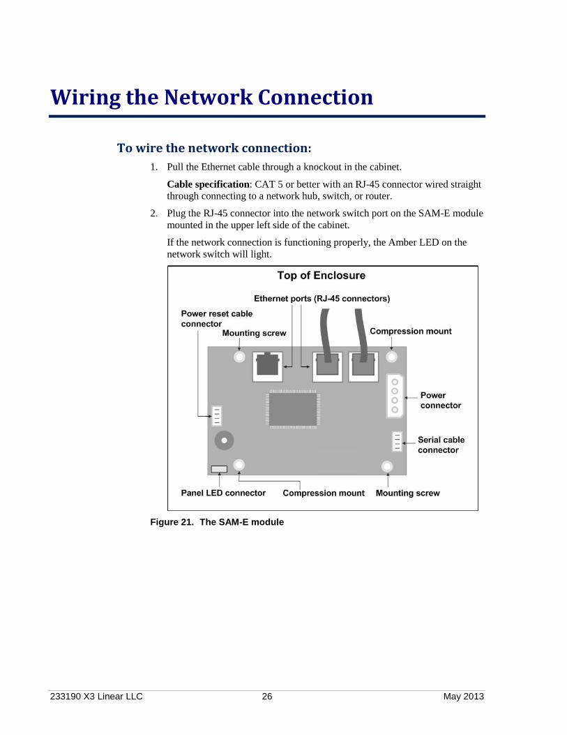
2. Plug the RJ-45 connector into the network switch port on the SAM-E module mounted in the upper left side of the cabinet.
If the network connection is functioning properly, the Amber LED on the network switch will light.
Figure 21. The SAM-E module

233190 X3 Linear LLC 27 May 2013
Wiring Power
This section describes how to wire the supplied PIP (Plug-in-Power supply) or a DC power source.
The PIP has not been investigated by UL, nor is it UL Listed.
WARNING: Do not apply power to the system until all connections have been made for readers, inputs, outputs, and temperature sensors.
Wiring the PIP Wire specification: Twisted 16 AWG Belden (2 conductor) or equivalent. Maximum distance: 10 feet (3.048 meters).
To wire the PIP: 1. Remove the supplied PIP from its packaging.
2. Attach the black, ground wire to the negative pin (pin 4) on the PIP.
3. Attach the red, positive wire to the positive pin (pin 1) on the PIP.
4. Prior to plugging in the PIP, pull the wiring through a knockout in the cabinet.
5. Connect the ground (black) wire to the left side of the terminal block.
6. Connect the positive (red) wire to the right side of the terminal block.
7. Plug in the PIP.
Wiring a DC Power Source Source power must come from a Listed UL 603 power-limited supply with its own breaker and an isolated earth ground.
If DC power is provided directly to the terminal block via a Listed UL 603 power-limited supply it must have 12V± 1% DC at a minimum of 5 Amps.
To wire DC power: 1. Ensure that the DC power source is off, and then and pull the wiring through
a knockout in the cabinet.
2. Connect the ground (black) wire to the left side of the terminal block, as shown in the following figure.

Wiring Power
233190 X3 Linear LLC 28 May 2013
Figure 22. Wiring DC power.
3. Connect the positive (red) wire to the right side of the terminal block.

233190 X3 Linear LLC 29 May 2013
Adding a Backup Battery
To install a battery backup for node and additional blades: Battery standby power has not been investigated by UL.
The network node does not include a battery, but one can be provided and mounted on the floor of the wall mount cabinet. The recommended battery is a 12 Volt Sealed or Valve Regulated Lead Acid type with a capacity of either 7AH or 12AH.
The battery cable is included but is not pre-installed. This cable has a 3-pin connector for the node (with the center position empty) and two quick connectors for the battery terminal tabs.
CAUTION: Do not connect the battery terminals and the node until power is supplied to the node.
The specified battery is not meant to function as a UPS, but rather to supply sufficient power for two to six hours of system function in case of power failure.
Do not connect a battery before external power is supplied. It will immediately power up the node and begin to drain the limited battery power. Once external power is supplied, you can connect the battery and it will charge at 12V via the connection with the node.
Figure 23. Network Node battery backup installed.

233190 X3 Linear LLC 30 May 2013
Setting Up a Small Configuration Network
Before connecting the controller to the corporate network, be sure to review the following information. You may need to set up a small network between the eMerge system and a PC that can be used to configure the system before it is connected to the corporate network.
Network Setup has not been evaluated by UL.
The system is configured with a factory default IP address of 192.168.0.250:
• If this is a valid address on a corporate network that is available for use, you can connect the system, in its factory default state, to the corporate network before configuring it. The corporate IT organization will be able to tell you if the default IP address is available on the corporate network.
• If the system’s default IP address is not available on the network, it will need to be changed during the initial software setup, to an address provided by the corporate IT organization.
Important: Do not connect the system to the corporate network until its IP address has been changed to a valid address on that network.
To allow the person who will complete the initial software setup to change the system’s IP address before connecting it to the network, you should create a small network between the eMerge system and the configuration PC.
To set up a configuration network: 1. Put an Ethernet switch between the eMerge system and the PC that will be
used for the initial software setup, as shown in the following figure.
Figure 24. A configuration network.

Setting Up a Small Configuration Network
233190 X3 Linear LLC 31 May 2013
The Ethernet switch can be of any size, but you should not use a switch that is already being used for another purpose.
2. Ensure that the person who will perform the initial software setup knows that the IP address of the configuration PC must be changed to a static value of 192.168.0.x (where x is a number between 100 and 200). For more information, refer to the “Initial Software Setup Guide.”

233190 X3 Linear LLC 32 May 2013
Testing and Troubleshooting
For testing and troubleshooting purposes, this section shows the layout of the DN2800MT board and the application extension blades. It also describes how to:
• Interpret various LEDs and beeps.
• Remove blades.
• Use buttons on the SAM-E module to start up, shut down, and reboot the system, and to reset the controller network and login factory defaults.
The Mini-ITX Network Controller The Mini-ITX Network Controller is shown in the following figure.
Figure 25. The Mini-ITX Network Controller.
Note: The single LED on the Mini-ITX Network Controller is green when the power is on and off when there is no power to the system.

Testing and Troubleshooting
233190 X3 Linear LLC 33 May 2013
Interpreting the System Status LED on the Cabinet Door LED State Meaning OFF System is down
BLINKING RED System is starting up or shutting down, but the controller does not see a gateway to a network
ON RED System is up, but the controller does not see a gateway to a network
BLINKING BLUE System is starting up or shutting down and the controller sees a gateway to the network
ON BLUE System is up and the controller sees a gateway to the network
Interpreting Beeps # of Beeps Meaning Shutting Down: Two beeps Most operating tasks have been completed and the
file system is about to be un-mounted. After waiting a few seconds, you can remove power.
Powering Up: One beep Startup is complete and you can log into the system.
This may take several minutes. Resetting System IP and Login Factory Defaults (via the hardware) Three beeps The IP and login factory defaults have been reset
via the REVERT button (see page 38).
Resetting System Configuration Factory Defaults (via the software)
Three beeps The system configuration factory defaults have been reset via the Initmode page in the UI, and the system is about to reboot.
Note: Unlike the controller, Network Nodes do not beep at any time. If readers are connected, you may hear beeps from the readers as they power up.

Testing and Troubleshooting
233190 X3 Linear LLC 34 May 2013
The Access Control Blade
Figure 26. Access Control Blade.
Input, Output, and Temperature Blades
Figure 27. Input, output, and temperature blades.

Testing and Troubleshooting
233190 X3 Linear LLC 35 May 2013
Interpreting Access Control, Input, Output, and Temperature Blade LEDs
The two LEDs located on an access control, input, output, or temperature blade are described in the following table.
LED Meaning LED #1 RUN ON GREEN means the blade is powered and has been
initialized. OFF means either the blade is not powered (check the ribbon cable connection) or the board is not initialized (reboot the node).
LED #2 I2C ON RED, BLINKS OFF indicates a state change on the input and/or output. This LED is normally OFF.
Removing Blades The procedure for removing blades will be necessary only if you need to swap out a blade for service reasons.
CAUTION: Blades are not hot-swappable. Before connecting or disconnecting blades in the cabinet, be sure to remove power from the system, after shutting down the system.
To remove a blade from the unit: 1. Log into the application.
2. Select Setup : System Maintenance : Utility.
3. Click the Shutdown now button to perform an orderly shutdown of the system.
Using the Shutdown utility will ensure that the security database is saved.
4. Once you hear a double beep, remove power from the system.
5. Be sure that you are grounded and remove all reader, output, and input connectors attached to the blade and label each with their connector position.
6. Unplug the ribbon cable by pushing outward on the two extraction levers. This will release out the cable connector.
7. Unthread the screw from the top of the standoff and remove the screw and lock washer.
8. Remove the blade from the slot in the chassis.

Testing and Troubleshooting
233190 X3 Linear LLC 36 May 2013
Using the Power, Reset, and Revert Buttons on the eMerge 50P/5000P
This section describes how to use the Power, Reset, and Revert buttons to:
• Start and shut down the system.
• Reboot the system if the software is unavailable.
• Reset the controller network and login factory defaults if you are unable to log into the system.
Figure 28. Power, Reset, and Revert buttons.
Using the Power Button When the system is not running, pressing the Power button starts the system. The system status LED blinks while the system is starting up. You will hear a single beep when the startup process is complete.

Testing and Troubleshooting
233190 X3 Linear LLC 37 May 2013
When the system is running, you can use the Power button to perform an orderly or hard shutdown:
• Momentarily pressing the Power button performs the same function as an orderly shutdown performed through the software. The system status LED starts to blink, indicating a shutdown of services. You will hear a double beep once the shutdown process is complete. To restart the controller after an orderly shutdown, momentarily press the Power button again.
• Holding down the Power button for longer than 5 seconds performs a hard shut down of the controller, killing all processes immediately. The system status LED blinks until the controller has shut down, at which point you can release the button. You will hear no beeps. To restart the controller after a hard shutdown, press the Power button momentarily, or power cycle the controller by turning off power to the system and then turning it back on. The system status LED will blink while the system is starting up, just as for a normal startup.
Note: If after 30 seconds following a power cycle the system status LED does not start to blink, momentarily press the Power button to start the controller.
Using the Reset Button Although you should use the software to reboot the system, you can use the Reset button if the software is unavailable. The results of the reboot operation will be slightly different, however, as described in the table below.
Pressing the Reset button performs the same function as a reboot performed through software, except that you will not hear a double beep indicating a reset. The system status LED goes out, and then starts blinking. Once the LED remains on and is not blinking, and you hear a single beep, the reset is complete.
Rebooting Using the Software Rebooting Using the RESET Button Performs an orderly shutdown of the database. Shuts down the system. Restarts the controller. Restarts communication between the controller and all the nodes.
Stops all processes without shutting down the database. The database will recover on startup, but the system must NOT be powered down or reset again while it recovers. Restarts the controller. Restarts communication between the controller and all the nodes.
Using the Revert Button If you are unable to log in to the security application because the system IP address or login name and password are unknown, you will need to use the hardware to revert to the controller network and login factory defaults.

Testing and Troubleshooting
233190 X3 Linear LLC 38 May 2013
Pressing the Revert button causes the controller to begin the revert process, indicated by a blinking system status LED. You will hear the following beeps:
• A triple beep indicating the factory defaults listed below have been restored.
• A double beep indicating the controller is restarting.
• A single beep indicating the revert process is complete, and you can login using the default, out-of-box settings.
The revert process does the following:
• Resets all controller network settings to their factory defaults: o The IP address is reset to 192.168.0.250. o The subnet mask is reset to 255.255.255.0. o The gateway, DNS 1, and DNS 2 are each reset to 192.168.0.1.
• Resets the web server port to port 80.
• Resets the password for the default administrator account to admin.
• Re-enables the administrator account, if necessary.
• Reassigns full system administrator rights to the default administrator account.
• Resets the interface language to English.
Note: Once the controller network and login factory defaults have been reset, you can change them at any time by selecting Setup : Site Settings : Network Controller. Click the Initmode link to change the network settings and the web server port number. Click the Localization link to change the interface language.

233190 X3 Linear LLC 39 May 2013
Hardware and Third-Party Device Specifications
Check the Linear web site (www.linearcorp.com) for updated specifications, lists of supported devices, and software updates.
Environmental Requirements
• Operating temperature range: 32° F to 120° F (0° C to 49° C).
• Operating relative humidity range: Up to 85% non-condensing.
Power Requirements
• If DC power is provided directly to the node board, it must have 12V± 1%DC at a minimum of 5 amps. Source power must come from a separatecircuit with its own breaker and an isolated earth ground via a UL 603 PowerLimited supply.
Reader Power Available from the eMerge System The total current that one eMerge system can provide to all readers is 1600 milliamps. Each access control blade can supply up to a total of 400 milliamps at 12VDC to readers. For example, an access control blade can supply 400 milliamps to one reader or 200 milliamps to each of two readers. If the readers require more current, or a different voltage, then power must be provided by a separate UL603 Limited-power supply.
For example, many Wiegand-compatible proximity readers from HID require 200 milliamps or less. The Node can power 8 readers, which is 8x200mA = 1.6A. Long range proximity readers may require more power. Refer to the reader manufacturer documentation for power specifications.
Other than readers, any other components in the system (such as magnetic locks) must have power provided separately.
Wiring Requirements and Specifications
• Inputs and Outputs: Twisted, shielded 22 AWG Belden #9462 orequivalent.Maximum distance from input/output devices to the eMerge system: 2000feet (610 meters).

Hardware and Third-Party Device Specifications
233190 X3 Linear LLC 40 May 2013
• Readers: Twisted, shielded 22 AWG Belden #9536 (6 conductor) or equivalent. Maximum distance from a reader to the eMerge system: 500 feet (152 meters).
• Temperature Sensors (not evaluated by UL): Up to 500 feet (152 meters) twisted Category 3; Over 500 feet up to 1000 feet (305 meters) twisted Category 5. Maximum distance from a temperature sensor to the eMerge system: 1000 feet (305 meters).
• Diodes required for output devices that are DC powered: 1N4002- 1 A, 50 V, Fast Recovery Diode or equivalent.
• Varistors (MOV) required for output devices that are AC powered: 40 VAC, 56 VDC, 10 A Surge, Radial Leaded Varistor or equivalent, such as World Products Inc. SNR-D56K2.
• Resistors required for input devices: 1k Ohms.
• Ethernet cable: CAT 5 cable or better with RJ-45 connector.
Readers The eMerge system’s access control blade supports card readers that use the UL listed 26 bit, 126 bit, and 200 bit Wiegand Reader Interface.
Cameras Cameras have not been evaluated by UL.
The controller supports up to 128 cameras. The exact number will depend on usage. IP video cameras may be connected directly to the network and driven by the controller. For UL application, IP cameras were not investigated.
At this release, the controller is tested to work with the following camera models:
• Axis: All VAPI-compliant cameras and models 2120, 232D
• IQinVision: Various IQeye models
• Panasonic: Models WV-NM100, WV-NS324
• Sony: Models SNC-DF40N/DF40P, SNC-P1, SNC-RZ30N
• Vivotek: Model IP2111

Hardware and Third-Party Device Specifications
233190 X3 Linear LLC 41 May 2013
Temperature Sensors
Operating Range:
-55º C to 100º C (-67° F to 212° F)
Accuracy: -1º/+5º C from -55º C to -30º C (-2º/+9º F from -67° F to -22° F)
-1º/+3º C from -30º C to 0º C (-2º/+5º F from -22° F to 32° F)
±0.5º C from 0º C to 70º C (±1º F from 32° F to 158° F)
±1º C from 70º C to 85º C (±2º F from 158° F to 185° F)
-2º/+1º C from 85º C to 100º C (-4º/+2º F from 185° F to 212° F)
Note: Temperature blades are not UL listed.
Software Protocols and Standards
• DBMS compatibility: SQL
• Email support: POP, SMTP
• Encryption: SSL, SHA-1
• Network: NTP, TCP/IP
• Web: HTTP, HTTPS, XML
Single Facility Maximum Capacities
• Access control readers: 32 maximum
• Access cards: 20,000
• Alarm monitoring points: 500
• Control point outputs: 500
• Digital video cameras: 32
• Temperature monitoring points: 500
• Network Nodes (fully populated): 32
Minimum System Configuration The minimum functional eMerge system would include one Mini-ITX Network Controller, one SAM-E module, one Network Node blade, and one application extension blade.

233190 X3 Linear LLC 42 May 2013
Index
A
access control blade available power for readers · 39 connecting inputs · 15 connecting outputs · 22 LEDs · 34
additional blades, installing · 9 additional information, references to · 1 application extension blades
connecting inputs and outputs · 12
B
battery backup for node and blades · 29
beeper control · 14 beeps, interpreting · 33 blades
access control · 13, 34 input · 16 installing · 9 removing · 35 temperature · 25
browser requirements · 5 bus, ribbon cable · 10
C
cabinet door LED · 33 cabinet, mounting · 8 cable specifications, Ethernet · 40 cameras supported · 40 card readers supported · 40 configuration network, setting up · 30 connecting to the network · 26 connectors, ribbon cable · 10 controller · 32 current, total available for readers · 39
D
DC power supply, wiring · 5, 27, 39 device specifications · 39 diodes and varistors, specifications · 40 dual resistor input circuits · 16
E
encryption · 41 environmental requirements · 6 Ethernet cable specifications · 40
H
hard shutdown · 37 hardware specifications · 39
I
input blade connecting inputs to · 15 LEDs · 34
input circuits dual resistor · 16 normally closed parallel resistor · 17 normally closed series resistor · 17 normally closed unsupervised · 18 normally open parallel resistor · 18 normally open series resistor · 19 normally open unsupervised · 19
inputs connecting · 15 specifications · 39 supervision types · 16 wiring · 14
installation overview checklist · 7
L
LED control, reader · 14 LEDs
on access control, input, output, and temperature blades · 35
on cabinet door · 33
M
Mini-ITX Network Controller · 3, 7, 15, 24, 32, 41 minimum system configuration · 41 mounting the cabinet · 8

Index
233190 X3 Linear LLC 43 May 2013
N
network connecting to · 26 for configuring the system · 30 requirements · 5
O
orderly shutdown · 37 output blade
connecting outputs to · 22 LEDs · 34
outputs connecting · 22 specifications · 39 wiring · 20
overview of the installation · 7
P
panel LED · 33 parallel resistor input circuits · 17, 18 part numbers for eMerge 2 · 7 position and slot numbers · 9 power requirements · 39 power source, wiring · 27 precautions and installation notes · 2
R
readers available power for · 39 beeper control · 14 connecting · 13 LED control · 14 specifications · 40 supported · 40 wiring · 12
rebooting the system · 37 requirements, system · 5 resetting network and login factory defaults · 37 resistor specifications · 40 restarting after a hard shutdown · 37 ribbon cable · 9, 11 ribbon cable connectors · 10 router, using to create a subnet · 4
S
SAM-E module · 26, 41
sensors, temperature · 25 series resistor input circuits · 17, 19 shutting down using the hardware · 37 slot and position numbers · 9 software protocols · 41 specifications, hardware and third-party devices · 39 static electricity precautions · 6 subnet · 5 system
requirements · 5 topology considerations · 3
system status LED · 33
T
temperature blade identifying · 25 LEDs · 34
temperature sensors connecting · 25 operating range and accuracy · 41 specifications · 40 wiring · 23
temperature, operating · 6, 39 testing and troubleshooting · 32 third-party device specifications · 39 topology considerations · 3
U
unsupervised input circuits · 18, 19 UPS · 29
V
varistors and diodes, specifications · 40
W
where to go for more information · 1 wiring
DC power source · 27 inputs · 14 outputs · 20 Plug-in-Power supply (PIP) · 27 readers · 12 requirements · 39 temperature sensors · 23 the network connection · 26