emc® data domain® dd9500 system installation guide · installation guide emc ... hardware...
TRANSCRIPT
Installation Guide
EMC® Data Domain® DD9500 System
Installation and Setup Guide302-001-641REV. 02
October 2015
This document provides installation and the setup instructions for the rack brackets,shelves, and the DD9500 system.
l Revision history......................................................................................................... 2l Related documentation..............................................................................................2l Tools and supplies needed........................................................................................ 3l Safety information..................................................................................................... 3l Description of the system...........................................................................................5l Define the Data Domain system information for your site......................................... 12l Unpack the system.................................................................................................. 13l Install the rack brackets...........................................................................................14l Install the DD9500 system into a rack...................................................................... 23l Mount the cable management assembly.................................................................. 26l Installing the expansion shelves into the racks........................................................ 30l Connecting the expansion shelves and the controller...............................................31l Install the bezel....................................................................................................... 47l Connect data cables................................................................................................ 48l Power on all systems............................................................................................... 48l Enable administrative communication..................................................................... 48l Accepting the End User License Agreement (EULA)................................................... 50l Run the configuration wizard....................................................................................50
Revision historyTable 1 Document revision history
Revision Date Document partnumber/Revisionnumber
Softwareversion
Description
02 October2015
302-001-641 REV 02 5.7 Supporting DS60 shelves
01 April 2015 302-001-641 REV 01 5.6 Initial publication
Related documentationEMC provides a variety of document types to support our products. End-user documentsinclude user guides, hardware installation guides, administrator guides, software guides,part replacement guides, release notes, and others. Integration documents describe howto integrate Data Domain systems with third party backup applications, and compatibilitymatrices show which components are compatible with each other.
This document refers to other EMC documents by title. To locate a referenced document,go to the EMC Support website at https://support.emc.com, enter the document title inthe search box, and click the search button.
Note
Hard copies of a document may be out of date. Always check for the current version of adocument before you start an upgrade or begin a significant configuration change.
Viewing Data Domain documentsProcedure
1. Log into the EMC Online support site at: https://support.emc.com.
2. To view user documents, click Product Documentation and then perform the followingsteps:
a. Select the Data Domain model from the Platform list and click View.
b. On the row for the correct Data Domain operating system (DD OS) version, clickView under Documentation.
c. Click the desired title.
3. To view integration-related documents, perform the following steps:
a. Click Integration Documentation.
b. Select the vendor from the Vendor dropdown list.
c. Select the desired title from the list.
4. To view compatibility matrices, perform the following steps:
a. Click Compatibility Matrices.
b. Select the desired title from the Current Releases list.
Installation Guide
2 EMC Data Domain DD9500 System Installation Guide
Where to go for more information
For information about: Go to https://support.emc.com/
How to configure the system EMC Data Domain Operating System InitialConfiguration Guide
New features, enhancements, known issues,and late-breaking news about your DataDomain software release
EMC Data Domain Operating System Release Notesfor your software release
How to manage the Data Domain operatingsystem
EMC Data Domain Operating SystemAdministration Guide for your software release
How to install and use the DD Boostsoftware and plug-in
EMC Data Domain Boost for OpenStorageAdministration Guide for your software release
How to replace Data Domain hardwarecomponents
Specific part installation guides
How to use third-party applications Integration documentation and compatibilitymatrices
Tools and supplies neededFor a list of recommended tools and supplies for field work, see the document titled FEToolkit Inventory and Common Procedures for FRU Tasks at https://support.emc.com.
Safety informationCAUTION
l If the system is used in a manner not specified by the manufacturer, the protectionprovided by the equipment may be impaired.
l The RJ45 sockets on the motherboard, PCI cards, or I/O modules are for Ethernetconnection only and must not be connected to a telecommunications network.
Review this list of important safety recommendations.
l All plug-in modules and blank plates are part of the fire enclosure and must beremoved only when a replacement can be added immediately. The system must notbe run without all parts in place.
l A DD9500 system must be operated only from a power supply input voltage range of200–240 VAC and 50–60 Hz. The ES30 shelves use 100-240 VAC and 50–60 Hz.
l Each component is intended to operate with all working power supplies installed.
l Provide a suitable power source with electrical overload protection.
l A safe electrical earth connection must be provided to each power cord. Check thegrounding of the power sources before applying power.
l The plug on each power supply cord is used as the main device to disconnect powerfrom the system. Ensure that the socket outlets are located near the equipment andare easily accessible.
Installation and Setup Guide
Where to go for more information 3
l Permanently unplug the unit if you think it is damaged in any way and before movingthe system. A DD9500 system includes four power supplies. To completely removesystem power, you must disconnect all four power supplies.
l The power connections must always be disconnected prior to removal or replacementof a power supply module from any of the components in the system.
l A faulty power supply module must be replaced within 24 hours.
l Do not lift system components by yourself. A DD9500 system weighs up to 117 lbs(53.2 kg) and an ES30 expansion shelf weighs up to 68 lbs (30.8 kg).
CAUTION
EMC Data Domain systems are heavy. Use at least two people or a mechanical lift tomove any system.
l Do not lift an expansion shelf by the handles on any modules. The handles are notdesigned to support the weight of the populated shelf.
l To comply with applicable safety, emission, and thermal requirements, covers mustnot be removed and all bays must be fitted with plug-in modules.
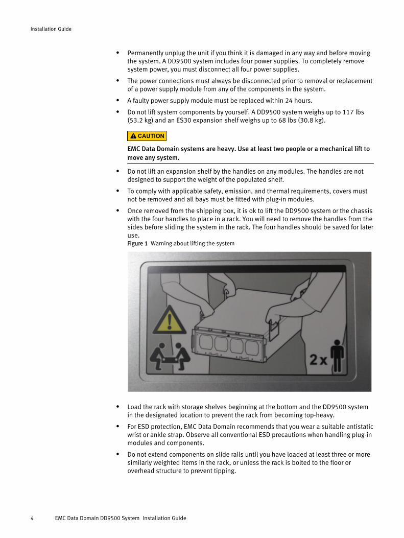
l Once removed from the shipping box, it is ok to lift the DD9500 system or the chassiswith the four handles to place in a rack. You will need to remove the handles from thesides before sliding the system in the rack. The four handles should be saved for lateruse.Figure 1 Warning about lifting the system
l Load the rack with storage shelves beginning at the bottom and the DD9500 systemin the designated location to prevent the rack from becoming top-heavy.
l For ESD protection, EMC Data Domain recommends that you wear a suitable antistaticwrist or ankle strap. Observe all conventional ESD precautions when handling plug-inmodules and components.
l Do not extend components on slide rails until you have loaded at least three or moresimilarly weighted items in the rack, or unless the rack is bolted to the floor oroverhead structure to prevent tipping.
Installation Guide
4 EMC Data Domain DD9500 System Installation Guide
Description of the systemThis section includes site requirements, product specifications, and descriptions of frontand rear panels.
Site requirementsSite requirements are described below.
l The controller requires 4U of vertical space in a rack. The ES30 expansion shelfrequires 3U. Use a standard 19”, four post rack. Do not use a two-post rack.
l Use air conditioning that can cope with the maximum BTU/hr thermal rating.
l Use adequate temperature control with a gradient (change) not to exceed 30°C/hr.
l In a closed or multi-unit rack, ensure that the unit has adequate airflow through thefront door and back door and that the ambient air temperature requirements are met.
l Ensure that the front bezel and back panel clearances are met.
l Ensure that cables at rear of unit do not obstruct exhaust airflow.
l If installing in a closed cabinet, ensure that the front and rear doors have at least65% open area to ensure adequate airflow for cooling.
l Front bezel requires 1.56 inches (4.0 cm) of unobstructed clearance.
l Back panel requires 5 inches (12.7 cm) of unobstructed clearance.
l AC power outlets must be provided with an earth ground conductor (safety ground). Asafe electrical earth connection must be provided to each power cord.
l Required voltage: 200-240 V~. Frequency: 50 to 60 Hz.
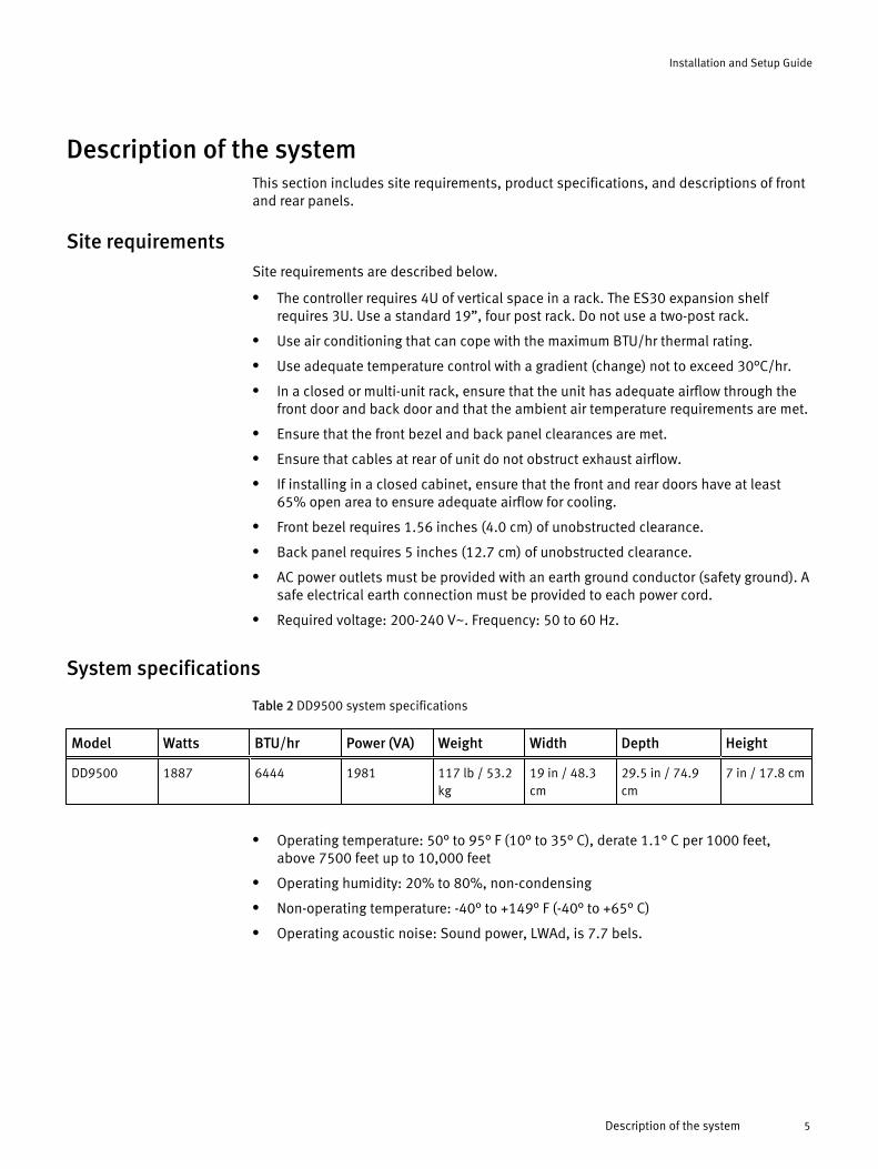
System specifications
Table 2 DD9500 system specifications
Model Watts BTU/hr Power (VA) Weight Width Depth Height
DD9500 1887 6444 1981 117 lb / 53.2kg
19 in / 48.3cm
29.5 in / 74.9cm
7 in / 17.8 cm
l Operating temperature: 50° to 95° F (10° to 35° C), derate 1.1° C per 1000 feet,above 7500 feet up to 10,000 feet
l Operating humidity: 20% to 80%, non-condensing
l Non-operating temperature: -40° to +149° F (-40° to +65° C)
l Operating acoustic noise: Sound power, LWAd, is 7.7 bels.
Installation and Setup Guide
Description of the system 5
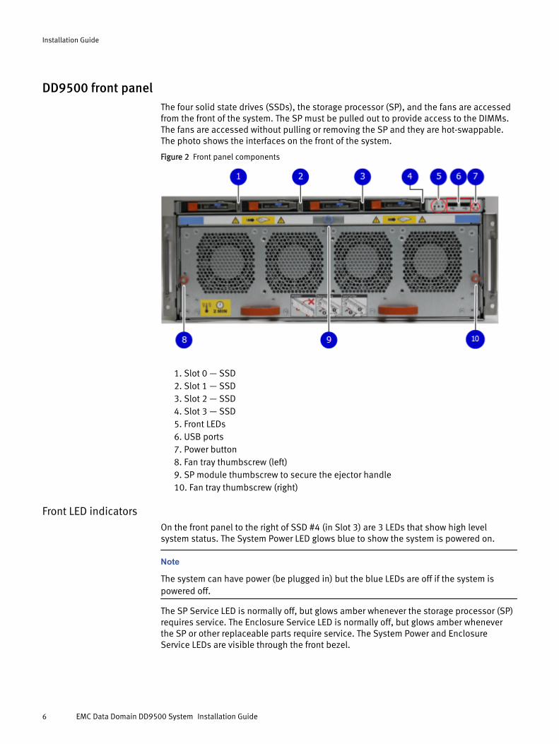
DD9500 front panelThe four solid state drives (SSDs), the storage processor (SP), and the fans are accessedfrom the front of the system. The SP must be pulled out to provide access to the DIMMs.The fans are accessed without pulling or removing the SP and they are hot-swappable.The photo shows the interfaces on the front of the system.
Figure 2 Front panel components
1. Slot 0 — SSD2. Slot 1 — SSD3. Slot 2 — SSD4. Slot 3 — SSD5. Front LEDs6. USB ports7. Power button8. Fan tray thumbscrew (left)9. SP module thumbscrew to secure the ejector handle10. Fan tray thumbscrew (right)
Front LED indicatorsOn the front panel to the right of SSD #4 (in Slot 3) are 3 LEDs that show high levelsystem status. The System Power LED glows blue to show the system is powered on.
Note
The system can have power (be plugged in) but the blue LEDs are off if the system ispowered off.
The SP Service LED is normally off, but glows amber whenever the storage processor (SP)requires service. The Enclosure Service LED is normally off, but glows amber wheneverthe SP or other replaceable parts require service. The System Power and EnclosureService LEDs are visible through the front bezel.
Installation Guide
6 EMC Data Domain DD9500 System Installation Guide
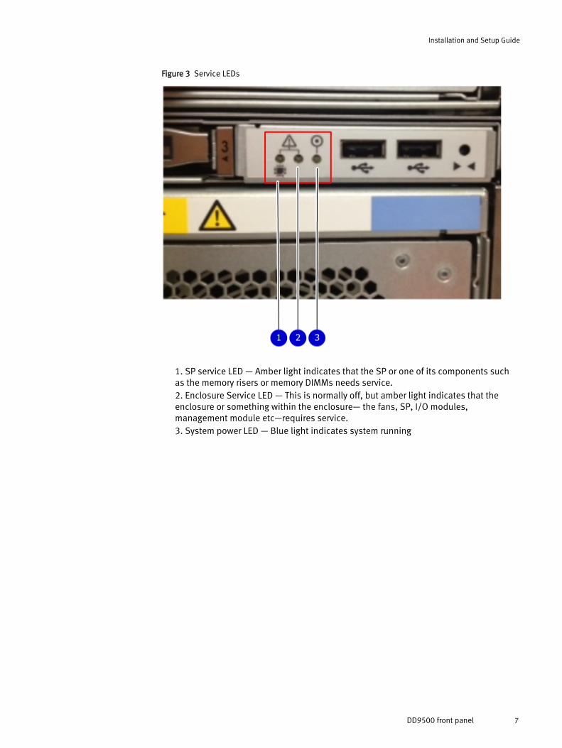
Figure 3 Service LEDs
1. SP service LED — Amber light indicates that the SP or one of its components suchas the memory risers or memory DIMMs needs service.2. Enclosure Service LED — This is normally off, but amber light indicates that theenclosure or something within the enclosure— the fans, SP, I/O modules,management module etc—requires service.3. System power LED — Blue light indicates system running
Installation and Setup Guide
DD9500 front panel 7
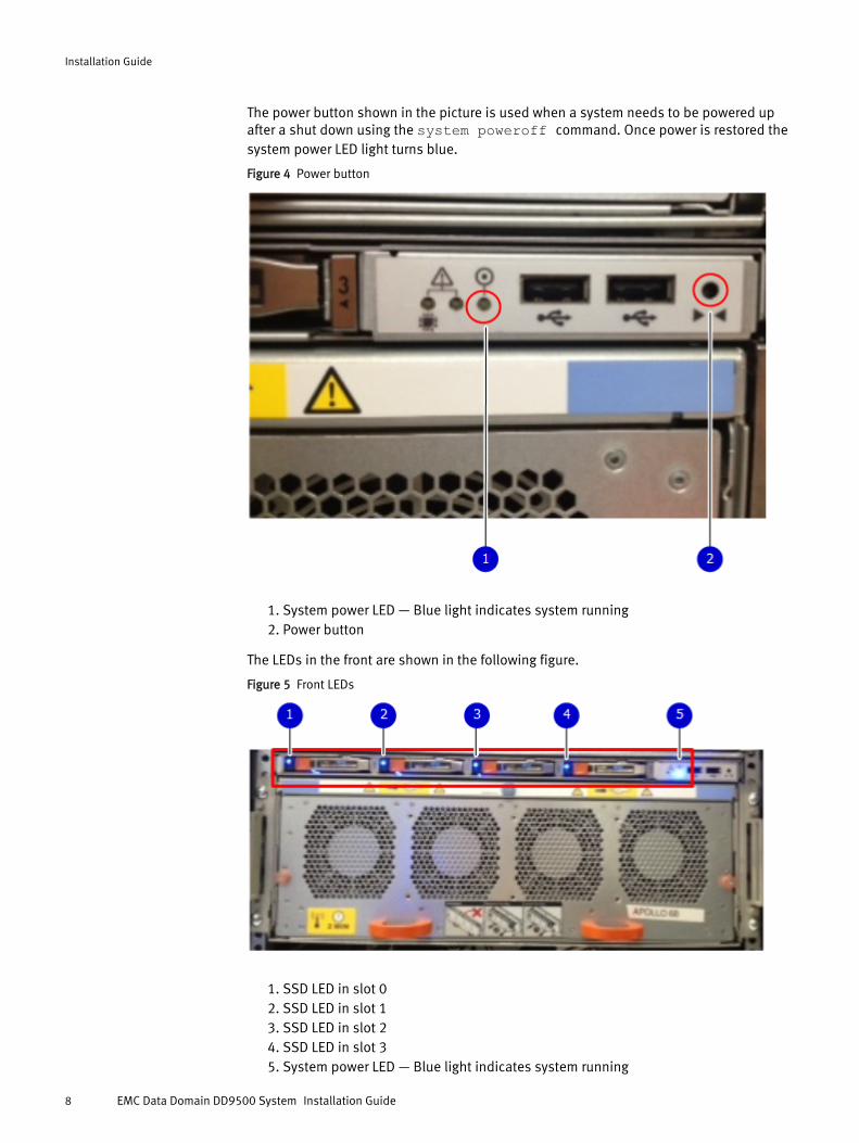
The power button shown in the picture is used when a system needs to be powered upafter a shut down using the system poweroff command. Once power is restored thesystem power LED light turns blue.
Figure 4 Power button
1. System power LED — Blue light indicates system running2. Power button
The LEDs in the front are shown in the following figure.
Figure 5 Front LEDs
1. SSD LED in slot 02. SSD LED in slot 13. SSD LED in slot 24. SSD LED in slot 35. System power LED — Blue light indicates system running
Installation Guide
8 EMC Data Domain DD9500 System Installation Guide
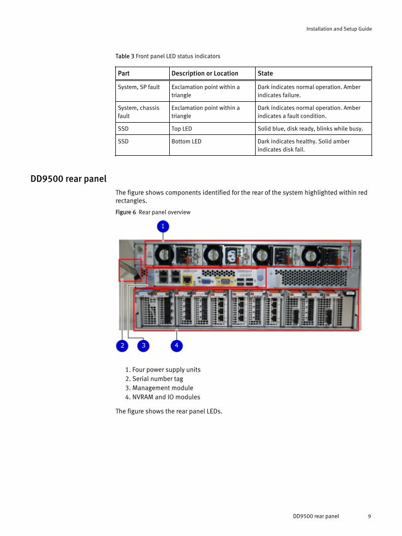
Table 3 Front panel LED status indicators
Part Description or Location State
System, SP fault Exclamation point within atriangle
Dark indicates normal operation. Amberindicates failure.
System, chassisfault
Exclamation point within atriangle
Dark indicates normal operation. Amberindicates a fault condition.
SSD Top LED Solid blue, disk ready, blinks while busy.
SSD Bottom LED Dark indicates healthy. Solid amberindicates disk fail.
DD9500 rear panelThe figure shows components identified for the rear of the system highlighted within redrectangles.
Figure 6 Rear panel overview
1. Four power supply units2. Serial number tag3. Management module4. NVRAM and IO modules
The figure shows the rear panel LEDs.
Installation and Setup Guide
DD9500 rear panel 9
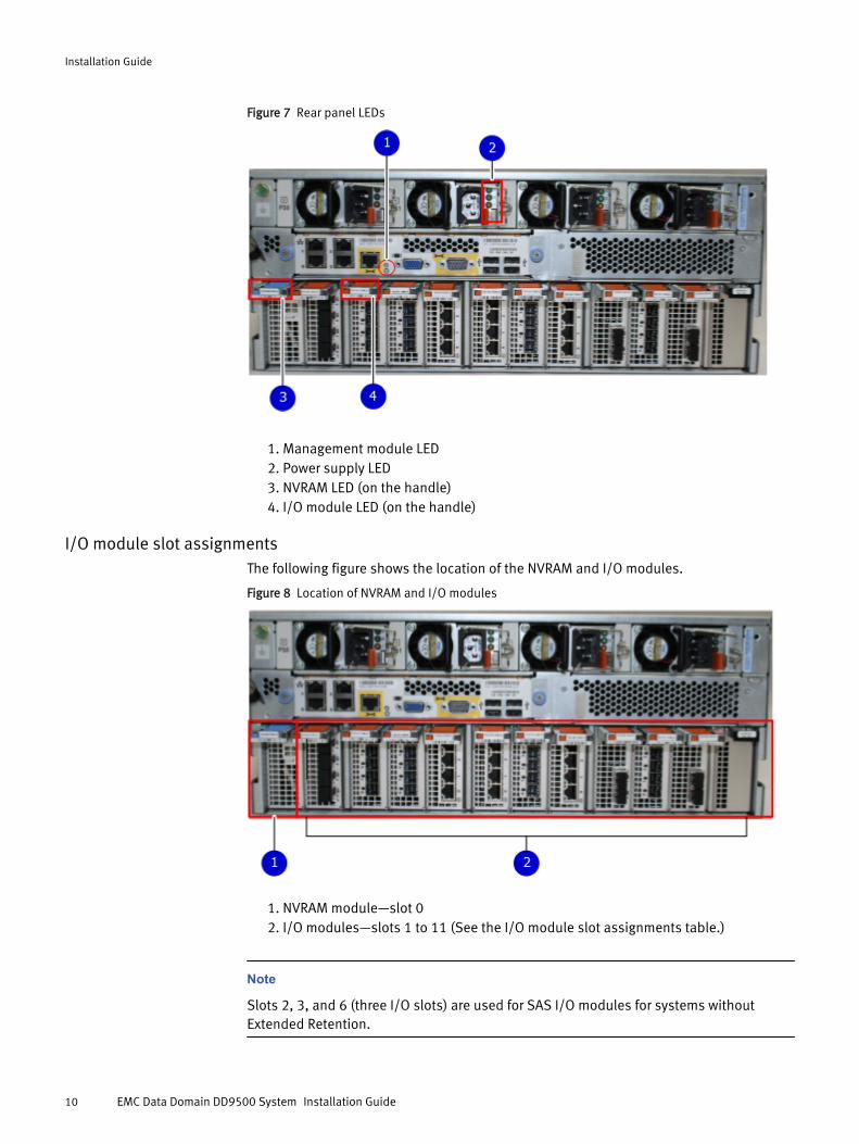
Figure 7 Rear panel LEDs
1. Management module LED2. Power supply LED3. NVRAM LED (on the handle)4. I/O module LED (on the handle)
I/O module slot assignmentsThe following figure shows the location of the NVRAM and I/O modules.
Figure 8 Location of NVRAM and I/O modules
1. NVRAM module—slot 02. I/O modules—slots 1 to 11 (See the I/O module slot assignments table.)
Note
Slots 2, 3, and 6 (three I/O slots) are used for SAS I/O modules for systems withoutExtended Retention.
Installation Guide
10 EMC Data Domain DD9500 System Installation Guide
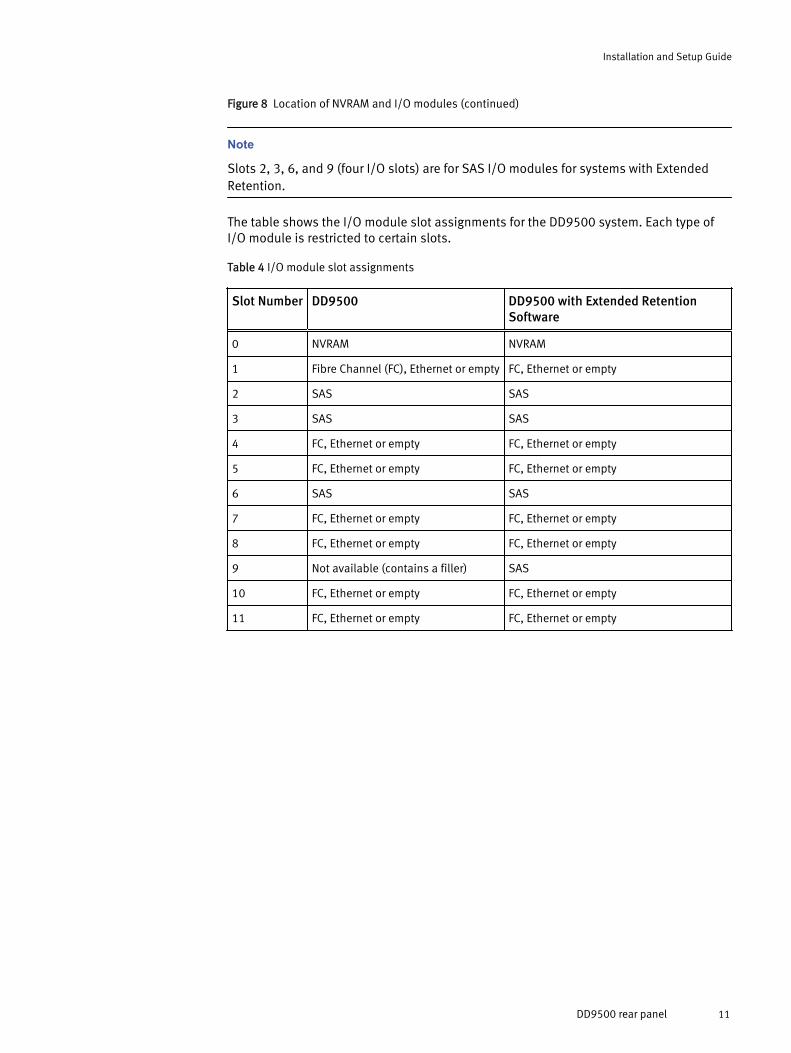
Figure 8 Location of NVRAM and I/O modules (continued)
Note
Slots 2, 3, 6, and 9 (four I/O slots) are for SAS I/O modules for systems with ExtendedRetention.
The table shows the I/O module slot assignments for the DD9500 system. Each type ofI/O module is restricted to certain slots.
Table 4 I/O module slot assignments
Slot Number DD9500 DD9500 with Extended RetentionSoftware
0 NVRAM NVRAM
1 Fibre Channel (FC), Ethernet or empty FC, Ethernet or empty
2 SAS SAS
3 SAS SAS
4 FC, Ethernet or empty FC, Ethernet or empty
5 FC, Ethernet or empty FC, Ethernet or empty
6 SAS SAS
7 FC, Ethernet or empty FC, Ethernet or empty
8 FC, Ethernet or empty FC, Ethernet or empty
9 Not available (contains a filler) SAS
10 FC, Ethernet or empty FC, Ethernet or empty
11 FC, Ethernet or empty FC, Ethernet or empty
Installation and Setup Guide
DD9500 rear panel 11
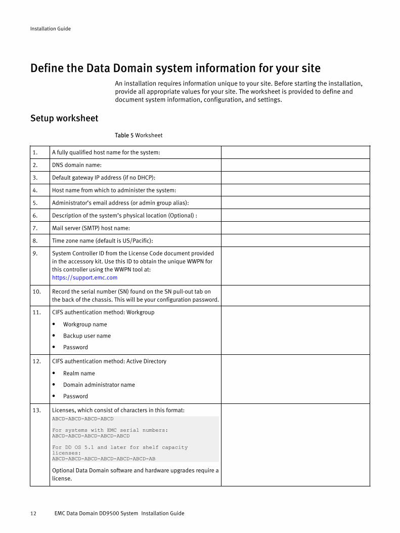
Define the Data Domain system information for your siteAn installation requires information unique to your site. Before starting the installation,provide all appropriate values for your site. The worksheet is provided to define anddocument system information, configuration, and settings.
Setup worksheet
Table 5 Worksheet
1. A fully qualified host name for the system:
2. DNS domain name:
3. Default gateway IP address (if no DHCP):
4. Host name from which to administer the system:
5. Administrator’s email address (or admin group alias):
6. Description of the system’s physical location (Optional) :
7. Mail server (SMTP) host name:
8. Time zone name (default is US/Pacific):
9. System Controller ID from the License Code document providedin the accessory kit. Use this ID to obtain the unique WWPN forthis controller using the WWPN tool at:https://support.emc.com
10. Record the serial number (SN) found on the SN pull-out tab onthe back of the chassis. This will be your configuration password.
11. CIFS authentication method: Workgroup
l Workgroup name
l Backup user name
l Password
12. CIFS authentication method: Active Directory
l Realm name
l Domain administrator name
l Password
13. Licenses, which consist of characters in this format:ABCD-ABCD-ABCD-ABCD
For systems with EMC serial numbers: ABCD-ABCD-ABCD-ABCD-ABCD
For DD OS 5.1 and later for shelf capacity licenses:ABCD-ABCD-ABCD-ABCD-ABCD-ABCD-AB
Optional Data Domain software and hardware upgrades require alicense.
Installation Guide
12 EMC Data Domain DD9500 System Installation Guide
Table 5 Worksheet (continued)
For a list of licensed features, see the EMC Data Domain OperatingSystem Administration Guide for your release.
For a list of new features that require a license, see the ReleaseNotes for your release.
14. If you are using DHCP (Dynamic Host Configuration Protocol), youmay need the MAC (Media Access Control) address, whichconsists of 12 alphanumeric characters. This is sometimes usedto configure the DHCP server, which assigns an IP address for aData Domain system. The MAC address is printed on a label andshould be visible. Its location varies according to system model.
15. If you are not using DHCP, have the following available:
l Interface IP addresses
l Interface netmasks - you can configure different networkinterfaces on a Data Domain system to different subnets.
l Routing gateway IP address - the IP address of the routinggateway.
l DNS server list - a comma-separated list of IP addresses ofyour DNS servers (only if you are using DNS).
l Site domain name - the domain name of the system, such ascompany.com.
l Fully qualified hostname for Data Domain system - thehostname of the system that includes the domain name,such as dd01.company.com
16. Other information:
17. Other information:
Unpack the system1. Remove the accessories and rail mount kit from the shipping packages.
2. Remove the controller and the bezels from the shipping packages.
Note
For field installations, the controller has temporary handles pre-fitted at the factory tohelp in removal of the system from the box and for placing it in a rack. While thecontroller is being placed in a rack, the handles attached to the chassis can beremoved by loosening the thumbscrew on each handle. The handles must be savedfor future use.
CAUTION
Data Domain systems are heavy. Always use two people or a mechanical lift to movea system. The chassis displays warning labels.
Installation and Setup Guide
Unpack the system 13
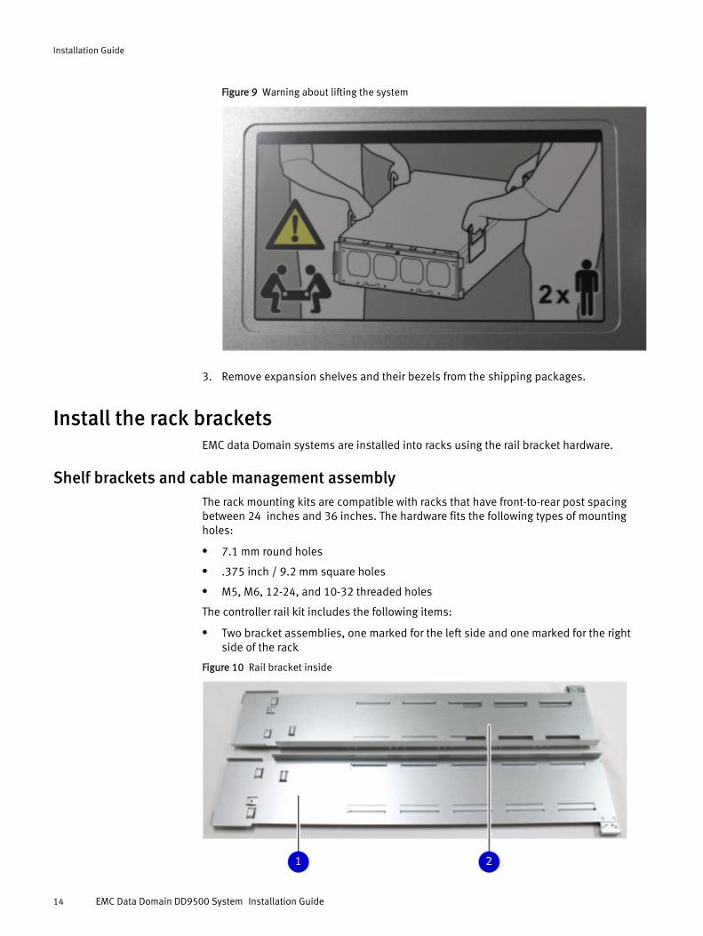
Figure 9 Warning about lifting the system
3. Remove expansion shelves and their bezels from the shipping packages.
Install the rack bracketsEMC data Domain systems are installed into racks using the rail bracket hardware.
Shelf brackets and cable management assemblyThe rack mounting kits are compatible with racks that have front-to-rear post spacingbetween 24 inches and 36 inches. The hardware fits the following types of mountingholes:
l 7.1 mm round holes
l .375 inch / 9.2 mm square holes
l M5, M6, 12-24, and 10-32 threaded holes
The controller rail kit includes the following items:
l Two bracket assemblies, one marked for the left side and one marked for the rightside of the rack
Figure 10 Rail bracket inside
Installation Guide
14 EMC Data Domain DD9500 System Installation Guide
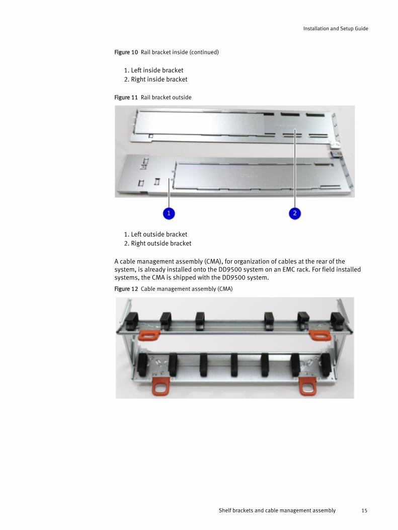
Figure 10 Rail bracket inside (continued)
1. Left inside bracket2. Right inside bracket
Figure 11 Rail bracket outside
1. Left outside bracket2. Right outside bracket
A cable management assembly (CMA), for organization of cables at the rear of thesystem, is already installed onto the DD9500 system on an EMC rack. For field installedsystems, the CMA is shipped with the DD9500 system.
Figure 12 Cable management assembly (CMA)
Installation and Setup Guide
Shelf brackets and cable management assembly 15
Install rail brackets on the Data Domain and EMC racks (for square or round holeracks)
Note
l If you are using a rack with threaded holes, skip this section and go to Install railbrackets using the adapter hardware (for threaded hole racks) on page 20 section.
l The Data Domain system is 4 rack units (RU) tall so make sure the location in the rackfits the product. Attach the bracket assembly to the lowest RU of the 4-RU opening.
l To comply with Data Domain rack mounting guidelines, the system controller shouldbe installed in the pre-defined space in the rack for system controllers. Refer to theInstallation and Setup Guide for your system.
l Do not hold the bracket assembly in a vertical position as the parts may separate.
Procedure
1. At each rack post, determine the vertical position in the rack where the brackets are tobe installed. The top-most mounting hole for a particular rack unit (RU) mountingposition is typically identified by a mark or hole. The bracket will be installed in thebottom hole of the 4 RU opening.
CAUTION
If the bracket is mounted in holes that are not vertically aligned from front to back,the bracket may be damaged and mounting will not be secure.
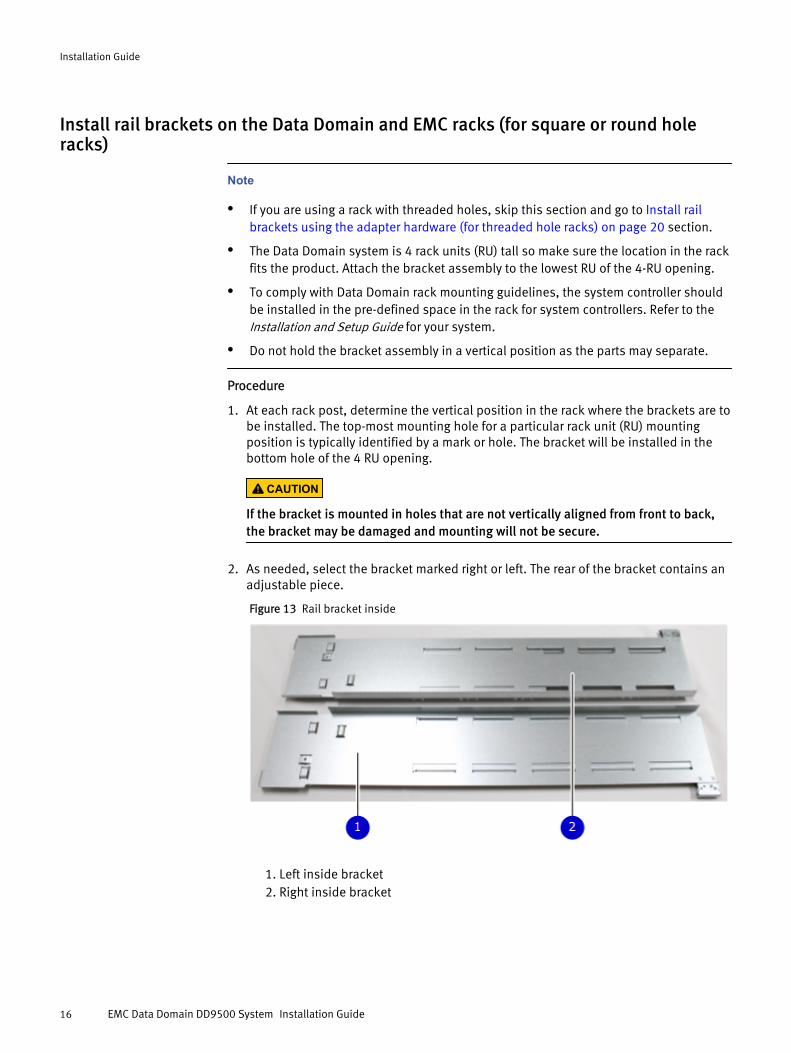
2. As needed, select the bracket marked right or left. The rear of the bracket contains anadjustable piece.
Figure 13 Rail bracket inside
1. Left inside bracket2. Right inside bracket
Installation Guide
16 EMC Data Domain DD9500 System Installation Guide
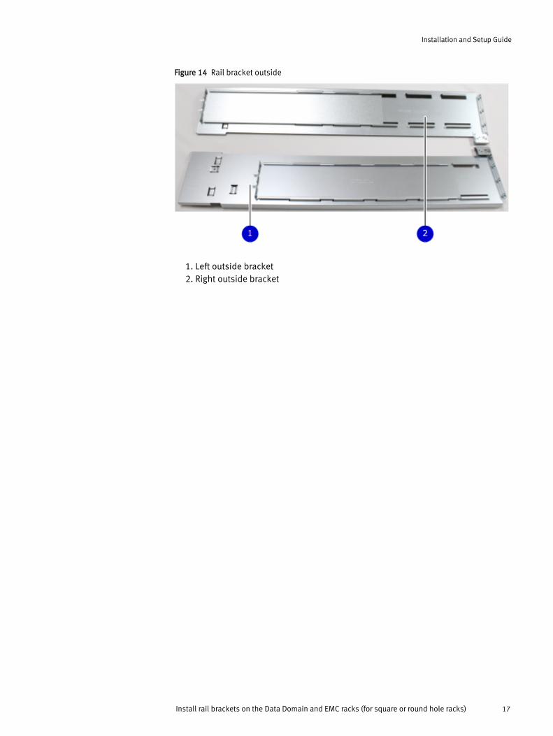
Figure 14 Rail bracket outside
1. Left outside bracket2. Right outside bracket
Installation and Setup Guide
Install rail brackets on the Data Domain and EMC racks (for square or round hole racks) 17
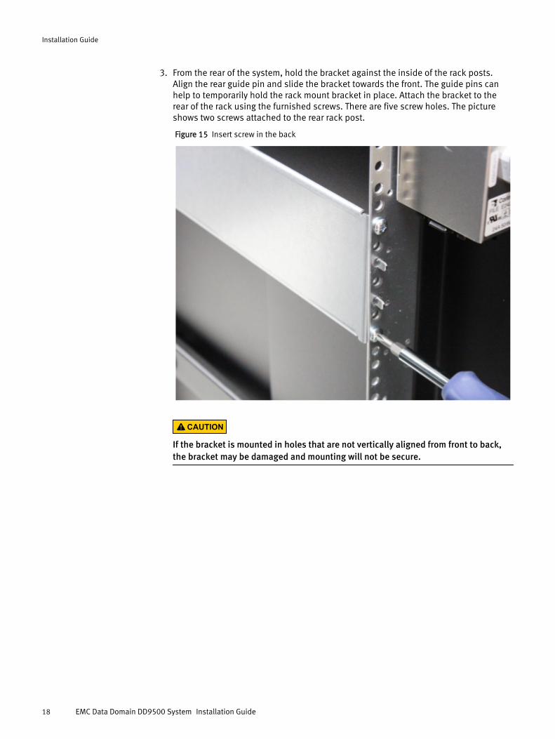
3. From the rear of the system, hold the bracket against the inside of the rack posts.Align the rear guide pin and slide the bracket towards the front. The guide pins canhelp to temporarily hold the rack mount bracket in place. Attach the bracket to therear of the rack using the furnished screws. There are five screw holes. The pictureshows two screws attached to the rear rack post.
Figure 15 Insert screw in the back
CAUTION
If the bracket is mounted in holes that are not vertically aligned from front to back,the bracket may be damaged and mounting will not be secure.
Installation Guide
18 EMC Data Domain DD9500 System Installation Guide
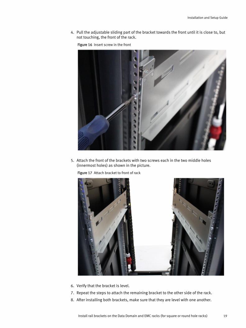
4. Pull the adjustable sliding part of the bracket towards the front until it is close to, butnot touching, the front of the rack.
Figure 16 Insert screw in the front
5. Attach the front of the brackets with two screws each in the two middle holes(innermost holes) as shown in the picture.
Figure 17 Attach bracket to front of rack
6. Verify that the bracket is level.
7. Repeat the steps to attach the remaining bracket to the other side of the rack.
8. After installing both brackets, make sure that they are level with one another.
Installation and Setup Guide
Install rail brackets on the Data Domain and EMC racks (for square or round hole racks) 19
Install rail brackets using the adapter hardware (for threaded hole racks)
Note
l If you are using a rack with square or round holes, go to Install rail brackets on theData Domain and EMC racks (for square or round hole racks) on page 16 section.
l Only use this procedure if your rack has tapped holes that are M5, M6, 10/32, or12/24.
l The adapter hardware is shipped in the rack mount kit.
l You will need a long handled screwdriver with a shank diameter less than 7.0 mmand the wrench (included in the kit) to tighten the nuts.
Procedure
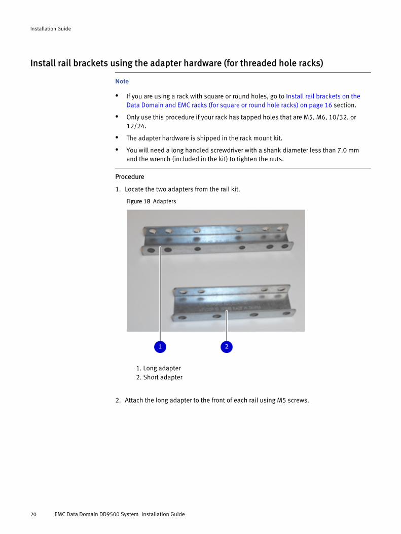
1. Locate the two adapters from the rail kit.
Figure 18 Adapters
1. Long adapter2. Short adapter
2. Attach the long adapter to the front of each rail using M5 screws.
Installation Guide
20 EMC Data Domain DD9500 System Installation Guide
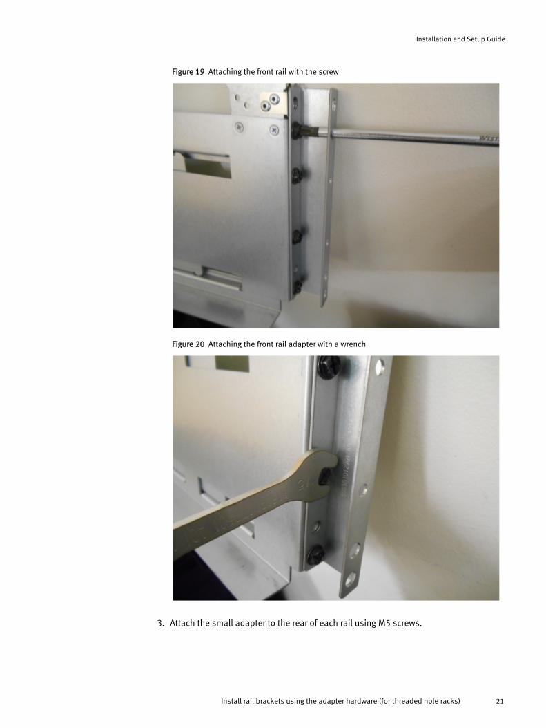
Figure 19 Attaching the front rail with the screw
Figure 20 Attaching the front rail adapter with a wrench
3. Attach the small adapter to the rear of each rail using M5 screws.
Installation and Setup Guide
Install rail brackets using the adapter hardware (for threaded hole racks) 21
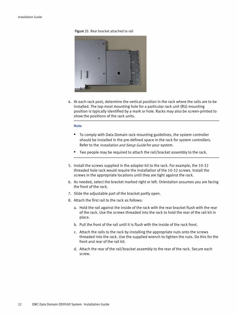
Figure 21 Rear bracket attached to rail
4. At each rack post, determine the vertical position in the rack where the rails are to beinstalled. The top-most mounting hole for a particular rack unit (RU) mountingposition is typically identified by a mark or hole. Racks may also be screen-printed toshow the positions of the rack units.
Note
l To comply with Data Domain rack mounting guidelines, the system controllershould be installed in the pre-defined space in the rack for system controllers.Refer to the Installation and Setup Guide for your system.
l Two people may be required to attach the rail/bracket assembly to the rack.
5. Install the screws supplied in the adapter kit to the rack. For example, the 10-32threaded hole rack would require the installation of the 10-32 screws. Install thescrews in the appropriate locations until they are tight against the rack.
6. As needed, select the bracket marked right or left. Orientation assumes you are facingthe front of the rack.
7. Slide the adjustable part of the bracket partly open.
8. Attach the first rail to the rack as follows:
a. Hold the rail against the inside of the rack with the rear bracket flush with the rearof the rack. Use the screws threaded into the rack to hold the rear of the rail kit inplace.
b. Pull the front of the rail until it is flush with the inside of the rack front.
c. Attach the rails to the rack by installing the appropriate nuts onto the screwsthreaded into the rack. Use the supplied wrench to tighten the nuts. Do this for thefront and rear of the rail kit.
d. Attach the rear of the rail/bracket assembly to the rear of the rack. Secure eachscrew.
Installation Guide
22 EMC Data Domain DD9500 System Installation Guide
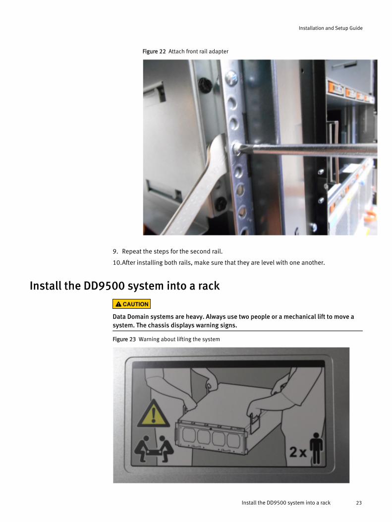
Figure 22 Attach front rail adapter
9. Repeat the steps for the second rail.
10.After installing both rails, make sure that they are level with one another.
Install the DD9500 system into a rackCAUTION
Data Domain systems are heavy. Always use two people or a mechanical lift to move asystem. The chassis displays warning signs.
Figure 23 Warning about lifting the system
Installation and Setup Guide
Install the DD9500 system into a rack 23
CAUTION
l To comply with Data Domain rack mounting guidelines, the system controller shouldbe installed in the pre-defined location for the system controller in the rack.
l Do not apply AC power to the DD9500 system controller until all expansion shelvesand cables are installed.
l Make sure the PSNT label, attached to the left rear of the chassis is not damaged orsnagged during the installation of the system into the rack.
Procedure
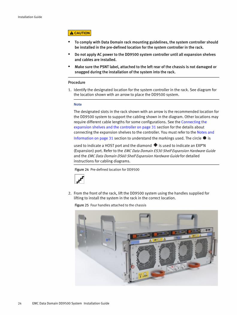
1. Identify the designated location for the system controller in the rack. See diagram forthe location shown with an arrow to place the DD9500 system.
Note
The designated slots in the rack shown with an arrow is the recommended location forthe DD9500 system to support the cabling shown in the diagram. Other locations mayrequire different cable lengths for some configurations. See the Connecting theexpansion shelves and the controller on page 31 section for the details aboutconnecting the expansion shelves to the controller. You must refer to the Notes and
Information on page 31 section to understand the markings used. The circle is
used to indicate a HOST port and the diamond is used to indicate an EXP’N(Expansion) port. Refer to the EMC Data Domain ES30 Shelf Expansion Hardware Guideand the EMC Data Domain DS60 Shelf Expansion Hardware Guide for detailedinstructions for cabling diagrams.
Figure 24 Pre-defined location for DD9500
2. From the front of the rack, lift the DD9500 system using the handles supplied forlifting to install the system in the rack in the correct location.
Figure 25 Four handles attached to the chassis
Installation Guide
24 EMC Data Domain DD9500 System Installation Guide
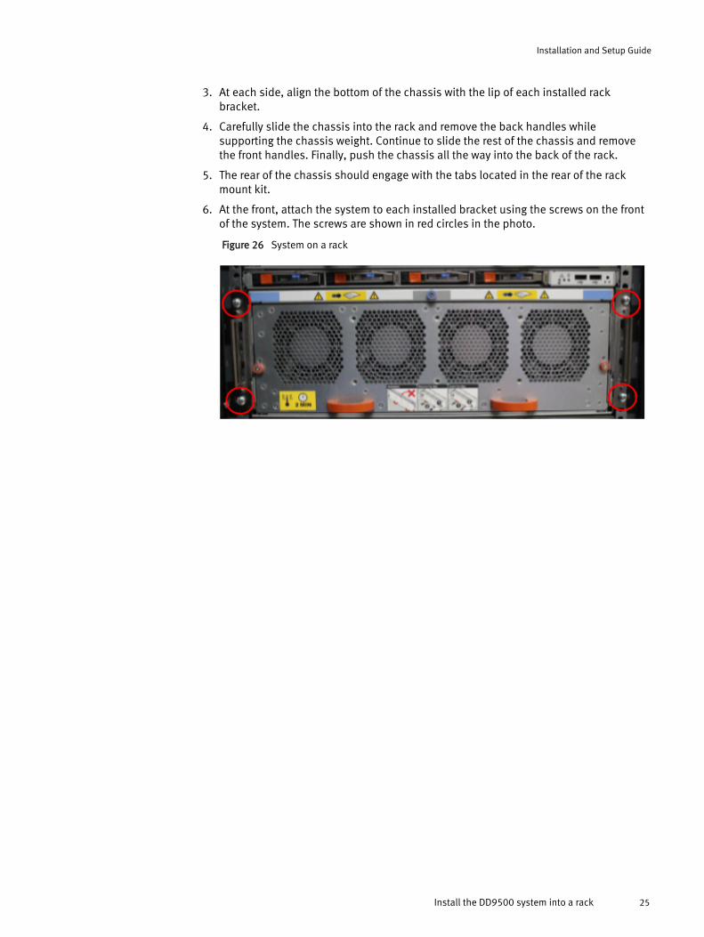
3. At each side, align the bottom of the chassis with the lip of each installed rackbracket.
4. Carefully slide the chassis into the rack and remove the back handles whilesupporting the chassis weight. Continue to slide the rest of the chassis and removethe front handles. Finally, push the chassis all the way into the back of the rack.
5. The rear of the chassis should engage with the tabs located in the rear of the rackmount kit.
6. At the front, attach the system to each installed bracket using the screws on the frontof the system. The screws are shown in red circles in the photo.
Figure 26 System on a rack
Installation and Setup Guide
Install the DD9500 system into a rack 25
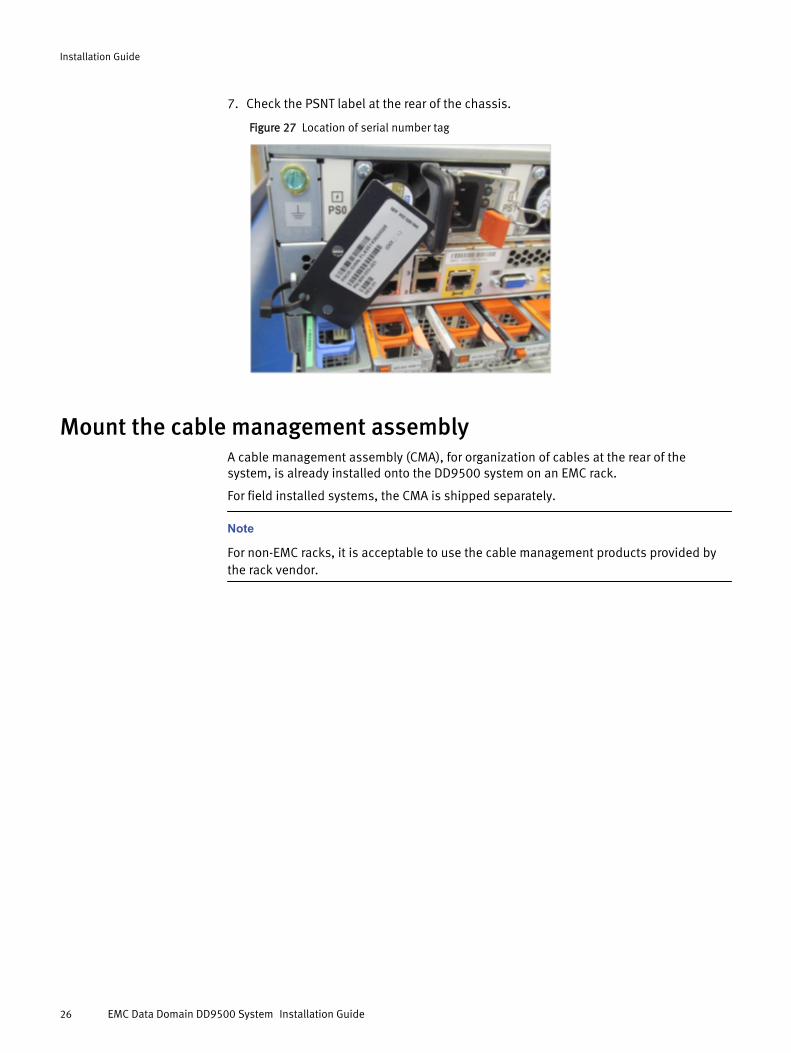
7. Check the PSNT label at the rear of the chassis.
Figure 27 Location of serial number tag
Mount the cable management assemblyA cable management assembly (CMA), for organization of cables at the rear of thesystem, is already installed onto the DD9500 system on an EMC rack.
For field installed systems, the CMA is shipped separately.
Note
For non-EMC racks, it is acceptable to use the cable management products provided bythe rack vendor.
Installation Guide
26 EMC Data Domain DD9500 System Installation Guide
Install the EMC cable management assembly (CMA)Procedure
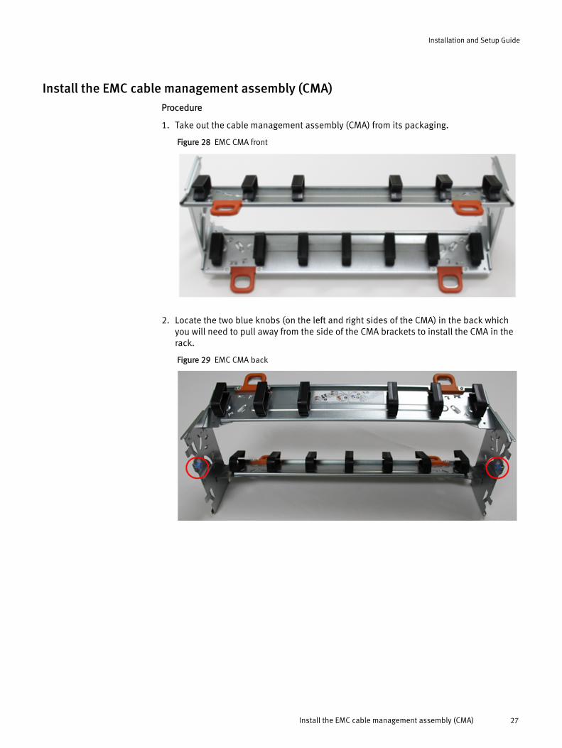
1. Take out the cable management assembly (CMA) from its packaging.
Figure 28 EMC CMA front
2. Locate the two blue knobs (on the left and right sides of the CMA) in the back whichyou will need to pull away from the side of the CMA brackets to install the CMA in therack.
Figure 29 EMC CMA back
Installation and Setup Guide
Install the EMC cable management assembly (CMA) 27
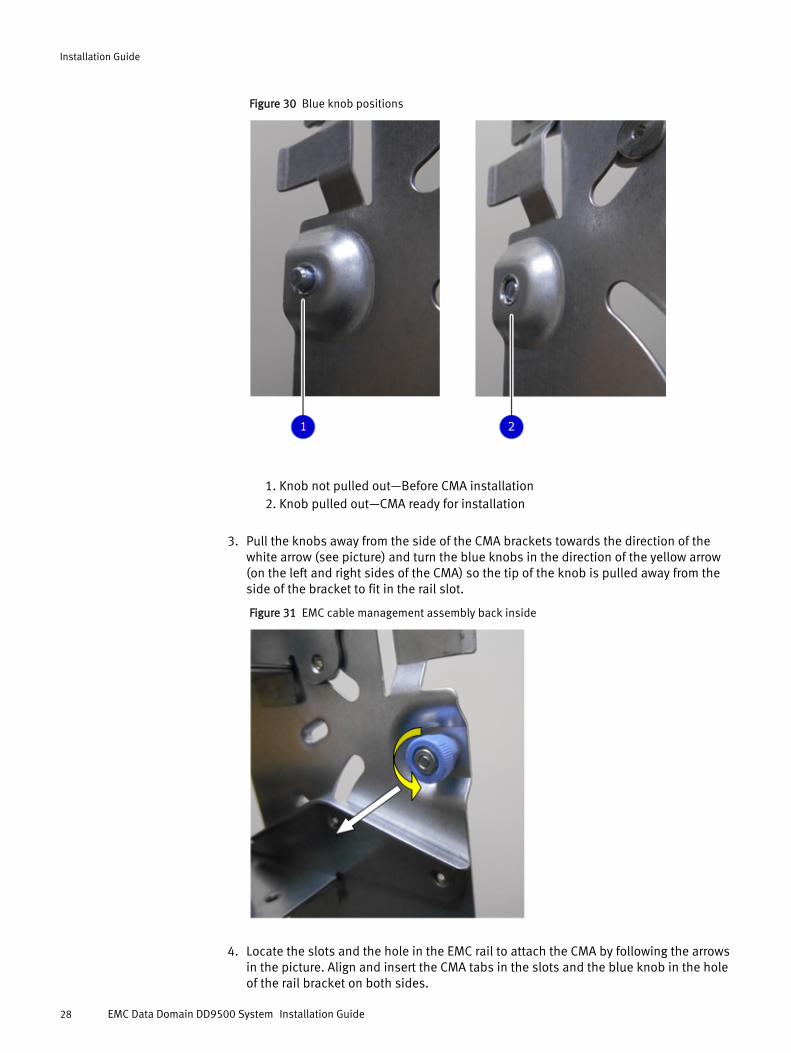
Figure 30 Blue knob positions
1. Knob not pulled out—Before CMA installation2. Knob pulled out—CMA ready for installation
3. Pull the knobs away from the side of the CMA brackets towards the direction of thewhite arrow (see picture) and turn the blue knobs in the direction of the yellow arrow(on the left and right sides of the CMA) so the tip of the knob is pulled away from theside of the bracket to fit in the rail slot.
Figure 31 EMC cable management assembly back inside
4. Locate the slots and the hole in the EMC rail to attach the CMA by following the arrowsin the picture. Align and insert the CMA tabs in the slots and the blue knob in the holeof the rail bracket on both sides.
Installation Guide
28 EMC Data Domain DD9500 System Installation Guide
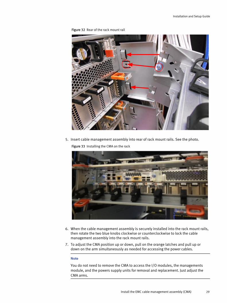
Figure 32 Rear of the rack mount rail
5. Insert cable management assembly into rear of rack mount rails. See the photo.
Figure 33 Installing the CMA on the rack
6. When the cable management assembly is securely installed into the rack mount rails,then rotate the two blue knobs clockwise or counterclockwise to lock the cablemanagement assembly into the rack mount rails.
7. To adjust the CMA position up or down, pull on the orange latches and pull up ordown on the arm simultaneously as needed for accessing the power cables.
Note
You do not need to remove the CMA to access the I/O modules, the managementsmodule, and the powers supply units for removal and replacement. Just adjust theCMA arms.
Installation and Setup Guide
Install the EMC cable management assembly (CMA) 29
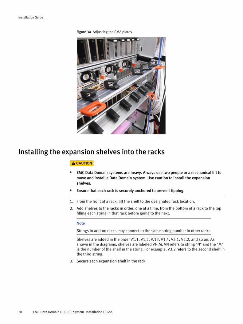
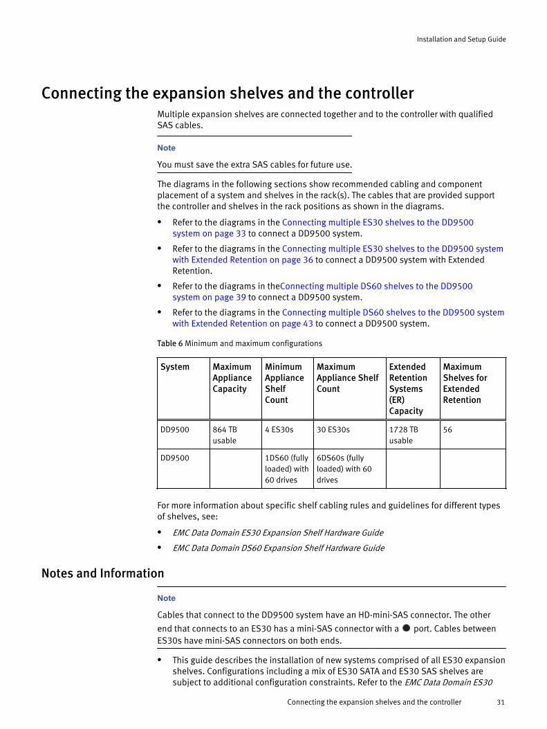
Figure 34 Adjusting the CMA plates
Installing the expansion shelves into the racksCAUTION
l EMC Data Domain systems are heavy. Always use two people or a mechanical lift tomove and install a Data Domain system. Use caution to install the expansionshelves.
l Ensure that each rack is securely anchored to prevent tipping.
1. From the front of a rack, lift the shelf to the designated rack location.
2. Add shelves to the racks in order, one at a time, from the bottom of a rack to the topfilling each string in that rack before going to the next.
Note
Strings in add-on racks may connect to the same string number in other racks.
Shelves are added in the order V1.1, V1.2, V.13, V1.4, V2.1, V2.2, and so on. Asshown in the diagrams, shelves are labeled VN.M. VN refers to string "N" and the "M"is the number of the shelf in the string. For example, V3.2 refers to the second shelf inthe third string.
3. Secure each expansion shelf in the rack.
Installation Guide
30 EMC Data Domain DD9500 System Installation Guide
Connecting the expansion shelves and the controllerMultiple expansion shelves are connected together and to the controller with qualifiedSAS cables.
Note
You must save the extra SAS cables for future use.
The diagrams in the following sections show recommended cabling and componentplacement of a system and shelves in the rack(s). The cables that are provided supportthe controller and shelves in the rack positions as shown in the diagrams.
l Refer to the diagrams in the Connecting multiple ES30 shelves to the DD9500system on page 33 to connect a DD9500 system.
l Refer to the diagrams in the Connecting multiple ES30 shelves to the DD9500 systemwith Extended Retention on page 36 to connect a DD9500 system with ExtendedRetention.
l Refer to the diagrams in theConnecting multiple DS60 shelves to the DD9500system on page 39 to connect a DD9500 system.
l Refer to the diagrams in the Connecting multiple DS60 shelves to the DD9500 systemwith Extended Retention on page 43 to connect a DD9500 system.
Table 6 Minimum and maximum configurations
System MaximumApplianceCapacity
MinimumApplianceShelfCount
MaximumAppliance ShelfCount
ExtendedRetentionSystems(ER)Capacity
MaximumShelves forExtendedRetention
DD9500 864 TBusable
4 ES30s 30 ES30s 1728 TBusable
56
DD9500 1DS60 (fullyloaded) with60 drives
6DS60s (fullyloaded) with 60drives
For more information about specific shelf cabling rules and guidelines for different typesof shelves, see:
l EMC Data Domain ES30 Expansion Shelf Hardware Guide
l EMC Data Domain DS60 Expansion Shelf Hardware Guide
Notes and Information
Note
Cables that connect to the DD9500 system have an HD-mini-SAS connector. The other
end that connects to an ES30 has a mini-SAS connector with a port. Cables betweenES30s have mini-SAS connectors on both ends.
l This guide describes the installation of new systems comprised of all ES30 expansionshelves. Configurations including a mix of ES30 SATA and ES30 SAS shelves aresubject to additional configuration constraints. Refer to the EMC Data Domain ES30
Installation and Setup Guide
Connecting the expansion shelves and the controller 31
Shelf Expansion Hardware Guide and the EMC Data Domain DS60 Shelf ExpansionHardware Guidefor detailed instructions for mixing shelf types.
l Cables have an HD-mini-SAS end that connects to the controller and a mini-SAS witha end that connects to the shelves.
l Cables should be dressed to the side of the rack and supported with Velcro straps toallow for easy removal, as needed, of system components. You must refer to the EMCData Domain ES30 Shelf Expansion Hardware Guide and the EMC Data Domain DS60Shelf Expansion Hardware Guide for detailed instructions for rack power connectiondiagrams for EMC racks.
CAUTION
The racking location can be matched in non-EMC racks; however, the powerconnections cannot be matched.
lThe shelf uses the markings to indicate a HOST port and to indicate an EXP’N(Expansion) port.
l Cabling between adjacent shelves in a string (loop) is done with the 1M SAS cablesthat are delivered with the shelves. The cables have the matching markings and
for identification.
l DD9500 system has a minimum of 3 SAS I/Os for the base system and 4 SAS I/Os forthe Extended Retention system.
Installation Guide
32 EMC Data Domain DD9500 System Installation Guide

Connecting multiple ES30 shelves to the DD9500 system1. Add shelf-to-shelf cables between shelves in a loop and to the controller as shown in
the diagram.
a. Cable from the B Controller EXPANSION port of the lower shelf to the Bcontroller HOST port of the next higher shelf.
b. Then cable from the A Controller HOST port of lower shelf to the A controller
EXPANSION port of the next higher shelf
2. Refer to the diagram for port connections.Figure 35 Cabling for a DD9500 system
3. Refer to the cabling instructions in the table.
Table 7 Cabling instructions
String(Loop)
I/O - Port Shelf Port Length*
1 I/O 3 - Port 1 B controller HOST port of shelf V1.1 2M
1 I/O 2 - Port 0 A controller HOST port of the highest number shelfin V1
2M
Installation and Setup Guide
Connecting multiple ES30 shelves to the DD9500 system 33
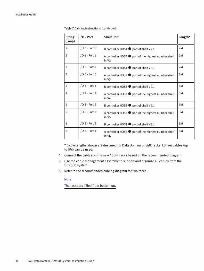
Table 7 Cabling instructions (continued)
String(Loop)
I/O - Port Shelf Port Length*
2 I/O 3 - Port 0 B controller HOST port of shelf V2.1 2M
2 I/O 6 - Port 1 A controller HOST port of the highest number shelfin V2
2M
3 I/O 2 - Port 1 B controller HOST port of shelf V3.1 2M
3 I/O 6 - Port 0 A controller HOST port of the highest number shelfin V3
2M
4 I/O 3 - Port 3 B controller HOST port of shelf V4.1 3M
4 I/O 2 - Port 2 A controller HOST port of the highest number shelfin V4
3M
5 I/O 3 - Port 2 B controller HOST port of shelf V5.1 3M
5 I/O 6 - Port 2 A controller HOST port of the highest number shelfin V5
3M
6 I/O 2 - Port 3 B controller HOST port of shelf V6.1 3M
6 I/O 6 - Port 3 A controller HOST port of the highest number shelfin V6
3M
* Cable lengths shown are designed for Data Domain or EMC racks. Longer cables (upto 5M) can be used.
4. Connect the cables on the new 40U-P racks based on the recommended diagram.
5. Use the cable management assembly to support and organize all cables from theDD9500 system.
6. Refer to the recommended cabling diagram for two racks.
Note
The racks are filled from bottom up.
Installation Guide
34 EMC Data Domain DD9500 System Installation Guide
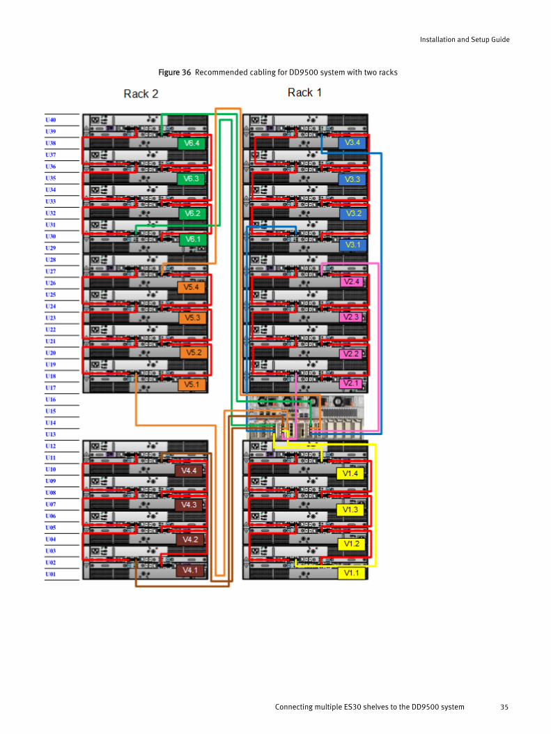
Figure 36 Recommended cabling for DD9500 system with two racks
Installation and Setup Guide
Connecting multiple ES30 shelves to the DD9500 system 35
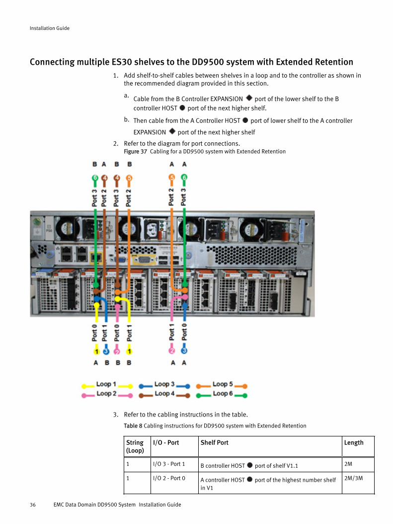
Connecting multiple ES30 shelves to the DD9500 system with Extended Retention1. Add shelf-to-shelf cables between shelves in a loop and to the controller as shown in
the recommended diagram provided in this section.
a. Cable from the B Controller EXPANSION port of the lower shelf to the Bcontroller HOST port of the next higher shelf.
b. Then cable from the A Controller HOST port of lower shelf to the A controller
EXPANSION port of the next higher shelf
2. Refer to the diagram for port connections.Figure 37 Cabling for a DD9500 system with Extended Retention
3. Refer to the cabling instructions in the table.
Table 8 Cabling instructions for DD9500 system with Extended Retention
String(Loop)
I/O - Port Shelf Port Length
1 I/O 3 - Port 1 B controller HOST port of shelf V1.1 2M
1 I/O 2 - Port 0 A controller HOST port of the highest number shelfin V1
2M/3M
Installation Guide
36 EMC Data Domain DD9500 System Installation Guide
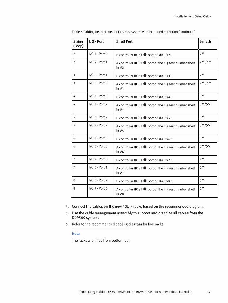
Table 8 Cabling instructions for DD9500 system with Extended Retention (continued)
String(Loop)
I/O - Port Shelf Port Length
2 I/O 3 - Port 0 B controller HOST port of shelf V2.1 2M
2 I/O 9 - Port 1 A controller HOST port of the highest number shelfin V2
2M /5M
3 I/O 2 - Port 1 B controller HOST port of shelf V3.1 2M
3 I/O 6 - Port 0 A controller HOST port of the highest number shelfin V3
2M /5M
4 I/O 3 - Port 3 B controller HOST port of shelf V4.1 3M
4 I/O 2 - Port 2 A controller HOST port of the highest number shelfin V4
3M/5M
5 I/O 3 - Port 2 B controller HOST port of shelf V5.1 3M
5 I/O 9 - Port 2 A controller HOST port of the highest number shelfin V5
3M/5M
6 I/O 2 - Port 3 B controller HOST port of shelf V6.1 3M
6 I/O 6 - Port 3 A controller HOST port of the highest number shelfin V6
3M/5M
7 I/O 9 - Port 0 B controller HOST port of shelf V7.1 2M
7 I/O 6 - Port 1 A controller HOST port of the highest number shelfin V7
5M
8 I/O 6 - Port 2 B controller HOST port of shelf V8.1 5M
8 I/O 9 - Port 3 A controller HOST port of the highest number shelfin V8
5M
4. Connect the cables on the new 40U-P racks based on the recommended diagram.
5. Use the cable management assembly to support and organize all cables from theDD9500 system.
6. Refer to the recommended cabling diagram for five racks.
Note
The racks are filled from bottom up.
Installation and Setup Guide
Connecting multiple ES30 shelves to the DD9500 system with Extended Retention 37
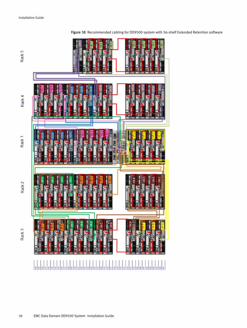
Figure 38 Recommended cabling for DD9500 system with 56-shelf Extended Retention software
Installation Guide
38 EMC Data Domain DD9500 System Installation Guide
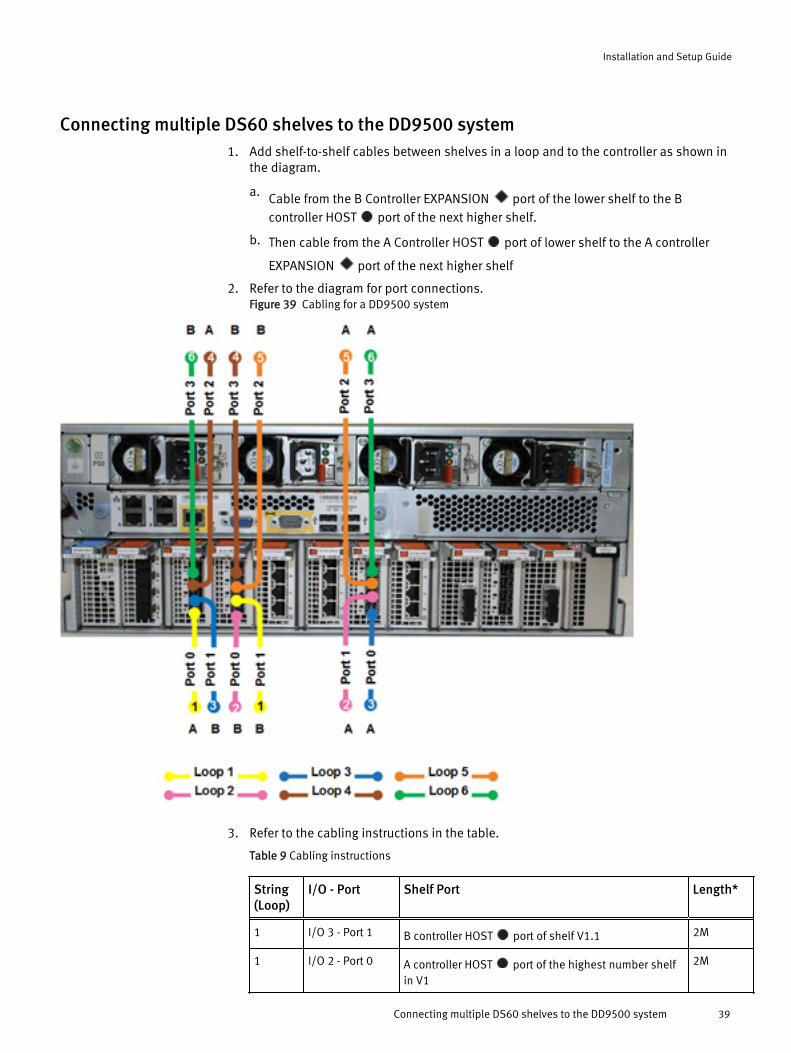
Connecting multiple DS60 shelves to the DD9500 system1. Add shelf-to-shelf cables between shelves in a loop and to the controller as shown in
the diagram.
a. Cable from the B Controller EXPANSION port of the lower shelf to the Bcontroller HOST port of the next higher shelf.
b. Then cable from the A Controller HOST port of lower shelf to the A controller
EXPANSION port of the next higher shelf
2. Refer to the diagram for port connections.Figure 39 Cabling for a DD9500 system
3. Refer to the cabling instructions in the table.
Table 9 Cabling instructions
String(Loop)
I/O - Port Shelf Port Length*
1 I/O 3 - Port 1 B controller HOST port of shelf V1.1 2M
1 I/O 2 - Port 0 A controller HOST port of the highest number shelfin V1
2M
Installation and Setup Guide
Connecting multiple DS60 shelves to the DD9500 system 39

Table 9 Cabling instructions (continued)
String(Loop)
I/O - Port Shelf Port Length*
2 I/O 3 - Port 0 B controller HOST port of shelf V2.1 2M
2 I/O 6 - Port 1 A controller HOST port of the highest number shelfin V2
2M
3 I/O 2 - Port 1 B controller HOST port of shelf V3.1 2M
3 I/O 6 - Port 0 A controller HOST port of the highest number shelfin V3
2M
4 I/O 3 - Port 3 B controller HOST port of shelf V4.1 3M
4 I/O 2 - Port 2 A controller HOST port of the highest number shelfin V4
3M
5 I/O 3 - Port 2 B controller HOST port of shelf V5.1 3M
5 I/O 6 - Port 2 A controller HOST port of the highest number shelfin V5
3M
6 I/O 2 - Port 3 B controller HOST port of shelf V6.1 3M
6 I/O 6 - Port 3 A controller HOST port of the highest number shelfin V6
3M
* Cable lengths shown are designed for Data Domain or EMC racks. Longer cables (upto 5M) can be used.
4. Connect the cables on the new 40U-P racks based on the recommended diagram.
5. Use the cable management assembly to support and organize all cables from theDD9500 system.
6. Refer to the recommended cabling diagram for two racks.
Note
The racks are filled from bottom up.
Installation Guide
40 EMC Data Domain DD9500 System Installation Guide
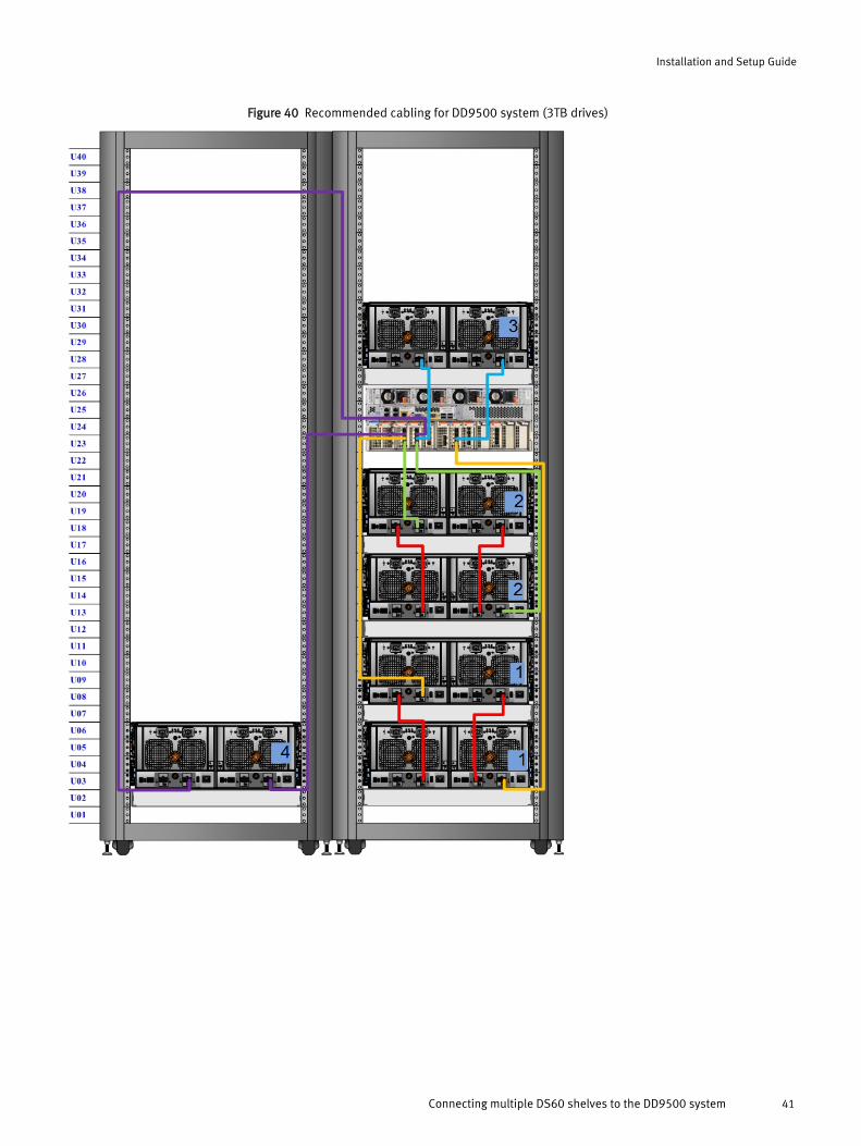
Figure 40 Recommended cabling for DD9500 system (3TB drives)
Installation and Setup Guide
Connecting multiple DS60 shelves to the DD9500 system 41
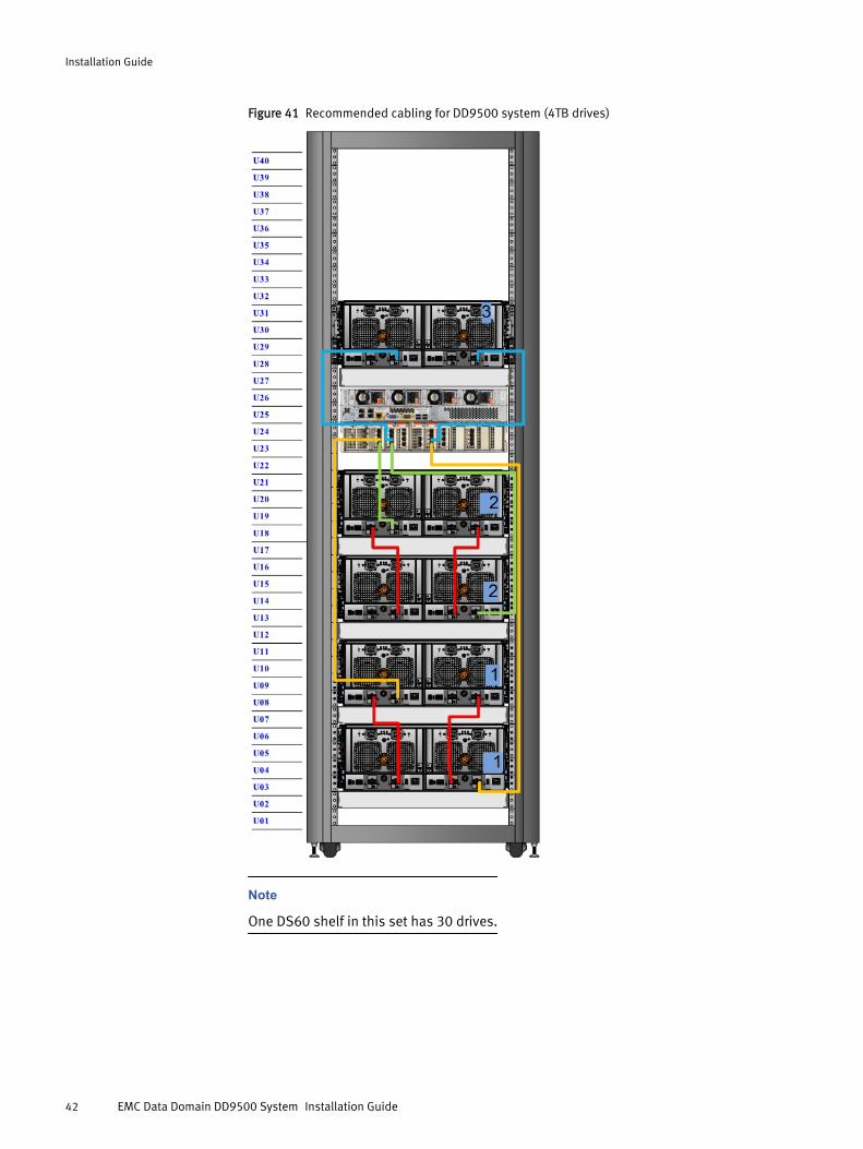
Figure 41 Recommended cabling for DD9500 system (4TB drives)
Note
One DS60 shelf in this set has 30 drives.
Installation Guide
42 EMC Data Domain DD9500 System Installation Guide
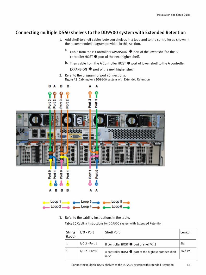
Connecting multiple DS60 shelves to the DD9500 system with Extended Retention1. Add shelf-to-shelf cables between shelves in a loop and to the controller as shown in
the recommended diagram provided in this section.
a. Cable from the B Controller EXPANSION port of the lower shelf to the Bcontroller HOST port of the next higher shelf.
b. Then cable from the A Controller HOST port of lower shelf to the A controller
EXPANSION port of the next higher shelf
2. Refer to the diagram for port connections.Figure 42 Cabling for a DD9500 system with Extended Retention
3. Refer to the cabling instructions in the table.
Table 10 Cabling instructions for DD9500 system with Extended Retention
String(Loop)
I/O - Port Shelf Port Length
1 I/O 3 - Port 1 B controller HOST port of shelf V1.1 2M
1 I/O 2 - Port 0 A controller HOST port of the highest number shelfin V1
2M/3M
Installation and Setup Guide
Connecting multiple DS60 shelves to the DD9500 system with Extended Retention 43
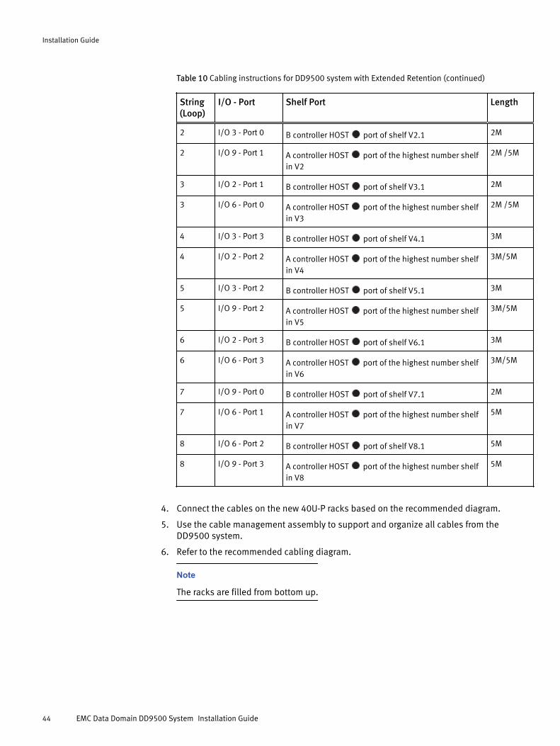
Table 10 Cabling instructions for DD9500 system with Extended Retention (continued)
String(Loop)
I/O - Port Shelf Port Length
2 I/O 3 - Port 0 B controller HOST port of shelf V2.1 2M
2 I/O 9 - Port 1 A controller HOST port of the highest number shelfin V2
2M /5M
3 I/O 2 - Port 1 B controller HOST port of shelf V3.1 2M
3 I/O 6 - Port 0 A controller HOST port of the highest number shelfin V3
2M /5M
4 I/O 3 - Port 3 B controller HOST port of shelf V4.1 3M
4 I/O 2 - Port 2 A controller HOST port of the highest number shelfin V4
3M/5M
5 I/O 3 - Port 2 B controller HOST port of shelf V5.1 3M
5 I/O 9 - Port 2 A controller HOST port of the highest number shelfin V5
3M/5M
6 I/O 2 - Port 3 B controller HOST port of shelf V6.1 3M
6 I/O 6 - Port 3 A controller HOST port of the highest number shelfin V6
3M/5M
7 I/O 9 - Port 0 B controller HOST port of shelf V7.1 2M
7 I/O 6 - Port 1 A controller HOST port of the highest number shelfin V7
5M
8 I/O 6 - Port 2 B controller HOST port of shelf V8.1 5M
8 I/O 9 - Port 3 A controller HOST port of the highest number shelfin V8
5M
4. Connect the cables on the new 40U-P racks based on the recommended diagram.
5. Use the cable management assembly to support and organize all cables from theDD9500 system.
6. Refer to the recommended cabling diagram.
Note
The racks are filled from bottom up.
Installation Guide
44 EMC Data Domain DD9500 System Installation Guide

Figure 43 Recommended cabling for DD9500 system (3TB drives) with Extended Retention software
Installation and Setup Guide
Connecting multiple DS60 shelves to the DD9500 system with Extended Retention 45
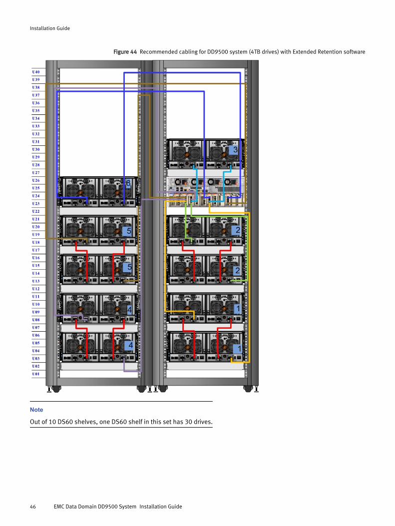
Figure 44 Recommended cabling for DD9500 system (4TB drives) with Extended Retention software
Note
Out of 10 DS60 shelves, one DS60 shelf in this set has 30 drives.
Installation Guide
46 EMC Data Domain DD9500 System Installation Guide
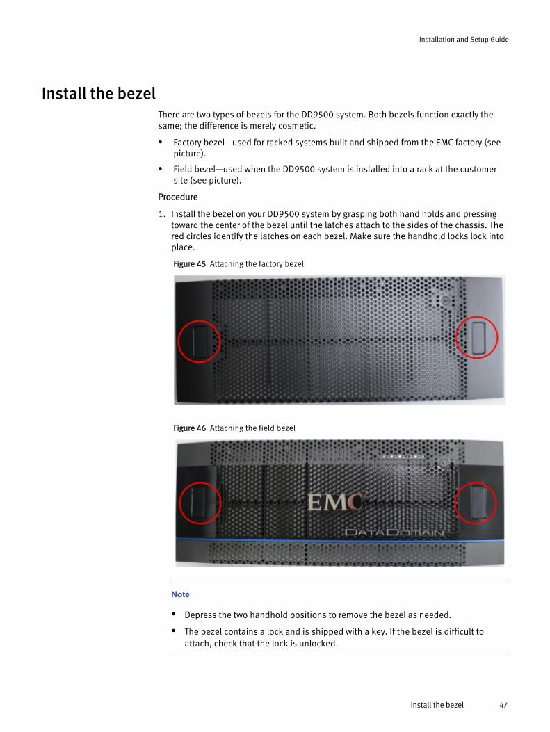
Install the bezelThere are two types of bezels for the DD9500 system. Both bezels function exactly thesame; the difference is merely cosmetic.
l Factory bezel—used for racked systems built and shipped from the EMC factory (seepicture).
l Field bezel—used when the DD9500 system is installed into a rack at the customersite (see picture).
Procedure
1. Install the bezel on your DD9500 system by grasping both hand holds and pressingtoward the center of the bezel until the latches attach to the sides of the chassis. Thered circles identify the latches on each bezel. Make sure the handhold locks lock intoplace.
Figure 45 Attaching the factory bezel
Figure 46 Attaching the field bezel
Note
l Depress the two handhold positions to remove the bezel as needed.
l The bezel contains a lock and is shipped with a key. If the bezel is difficult toattach, check that the lock is unlocked.
Installation and Setup Guide
Install the bezel 47

Connect data cables1. Enable data transfer Ethernet connectivity. Repeat for each connection.
a. If using 1 Gb copper Ethernet, attach a Cat 5e or Cat 6 copper Ethernet cable to anRJ-45 Ethernet network port (start with ethMa and go up).
b. If using 10 Gb copper Ethernet with an SFP+ connector, use a qualified SFP+copper cable.
c. If using 1/10 Gb fiber Ethernet, use MMF-850nm cables with LC duplexconnectors.
d. For 10GBaseT connections, use Cat6a S-STP Ethernet cables.
2. Enable data transfer Fibre Channel (FC) connectivity. Repeat for each connection.
a. Attach a Fibre Channel fiber optical cable (LC connector) to an I/O module port onthe controller, and attach the other end (LC connector) to an FC switch or to an FCport on your server.
Power on all systems
Note
Power on all expansion shelves first before powering on the controller.
1. Connect power cables to each expansion shelf receptacle and attach the retentionclips.
2. Provide power to power-on each expansion shelf. The shelves power on whenplugged in. Ensure that each shelf power cable is connected to a different powersource.
Note
Wait approximately 3 minutes after all expansion shelves are powered on beforepowering on the controller.
3. Provide power to power-on the controller. The system powers on when plugged in.
Note
The DD9500 system should be powered from redundant AC sources. This allows oneAC source to fail or be serviced without impacting system operation. PSU0 and PSU1should be attached to one AC source. PSU2 and PSU3 should be attached to theother AC source.
a. Connect power cables to each receptacle and attach the retention clips.
b. Ensure that each power supply is connected to a different power source.
Enable administrative communication
Note
See the back panel of the DD9500 system for the location of the onboard interfaces.
Installation Guide
48 EMC Data Domain DD9500 System Installation Guide
1. Connect an administrative console to the serial port on the back panel of the system.
2.Note
You must have 115200 baud rate for the DD9500 system to work properly; 9600baud rate will not work for the DD9500 system.
Launch a terminal emulation program from your computer and configure the followingcommunication settings:
Table 11 Communications settings
Setting Value
Baud rate 115200
Data bits 8
Stop bits 1
Parity None
Flow control None
Emulation VT-100
3. Select Enter on your keyboard to activate the console.
Note
If you do not see the prompt on your terminal to log in, then complete Step 4.
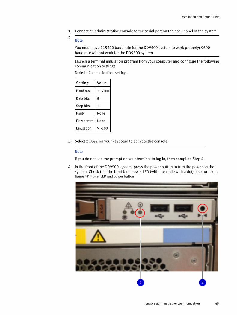
4. In the front of the DD9500 system, press the power button to turn the power on thesystem. Check that the front blue power LED (with the circle with a dot) also turns on.Figure 47 Power LED and power button
Installation and Setup Guide
Enable administrative communication 49
1. Power LED2. Power button
5.Note
The initial username is sysadmin and the initial password is the system serial
number.
Log into the Data Domain console using the sysadmin username.localhost.localdomain login: sysadmin
6. Enter the default password, which is the system serial number (SSN). The SSN is onthe attached tag on the rear panel of the system. See the rear panel of the DD9500system for the SSN tag.Password: system_serial_number
Note
If you enter an incorrect password four consecutive times, the system locks out thespecified username for 120 seconds. The login count and lockout period are configurableand might be different on your system. See the EMC Data Domain Operating SystemAdministration Guide and the EMC Data Domain Operating System Command ReferenceGuide for setting these values.
Accepting the End User License Agreement (EULA)The first time you log in to a Data Domain system, the End User License Agreement (EULA)is displayed.
At the end of the EULA, you are prompted to accept it:
Press any key then hit enter to acknowledge the receipt of EULA information
Note
The EULA must be accepted by a customer. An EMC representative should not accept thisagreement. If a customer is not present, press Ctrl-C to exit from the EULA acceptancescreen and continue the installation.
The customer can later enter the following to redisplay the EULA and accept it:
system show eula
Run the configuration wizardThe CLI configuration wizard starts automatically the first time the system boots. Thewizard prompts you through a series of questions that provide just enough informationfor initial system configuration and basic network connectivity.
Note
You can initiate the CLI configuration wizard manually by entering the config setupcommand.
Installation Guide
50 EMC Data Domain DD9500 System Installation Guide

Configuring the networkProcedure
1. Enter yes to begin configuring the system.
Do you want to configure system using GUI wizard (yes|no) [no]: yes
Answering yes initiates a shortened version of the CLI configuration wizard thatprovides enough information to configure the system for network access. Afterward,you can use the GUI (Data Domain System Manager) for additional configuration.Answering no initiates a longer, more robust, version of the CLI configuration wizard.
2. Enter yes and change the password.
Note
If you are an EMC internal resource or partner, do not change the password unlessspecifically directed to do so by the customer.
Change the 'sysadmin' password at this time? (yes|no):3. Enter yes to configure the system for network connectivity.
Network ConfigurationConfigure Network at this time (yes|no) [no]: yes
4. Enter yes to configure DHCP to obtain network parameters (such as, the hostname,domain name, and IP addresses) dynamically from a DHCP server. Or enter no toconfigure the parameters manually.
Use DHCPUse DHCP for hostname, domainname, default gateway andDNS servers? (At least one interface needs to be configuredusing DHCP) (yes|no|?)
5. Enter a fully qualified domain name (FQDN) for the hostname; for example,str01.yourcompany.com. Or accept the hostname, if the system was able todiscover it.
Enter the hostname for this system (fully-qualified domain name)[]:6. Enter the DNS domain name; for example, yourcompany.com. Or accept the domain
name, if the system was able to discover it.
DomainnameEnter your DNS domainname []:
7. Enable and configure each Ethernet interface. Accept or decline DHCP for eachinterface. If the port does not use DHCP to discover network parameters automatically,enter the information manually.
Ethernet port eth0aEnable Ethernet port eth0a (yes|no|?) [yes]: no
Ethernet port eth0bEnable Ethernet port eth0b (yes|no|?) [no]: yes
Use DHCP on Ethernet port eth0b (yes|no|?) [no]: Enter the IP address for eth0b[192.168.10.185]:
Enter the netmask for eth0b[255.255.255.0]:
Installation and Setup Guide
Configuring the network 51
8. Enter the IP address of the default routing gateway. Or accept the default gateway, ifthe system was able to discover it.
Default GatewayEnter the default gateway IP address: 192.168.10.1
9. Enter the IPv6 address of the default routing gateway. Or accept the IPv6 address ofthe default gateway, if the system was able to discover it. If IPv6 is not in use, leavethe field empty and press Enter to continue.
IPV6 Default GatewayEnter the ipv6 default gateway IP address:
10.Enter up to three DNS servers to use for resolving hostnames to IP addresses. Use acomma-separated or space-separated list. Enter a space for no DNS servers. Or acceptthe IP addresses of the DNS servers, if the system was able to discover them.
DNS ServersEnter the DNS Server list (zero, one, two or three IP addresses): 192.168.10.1
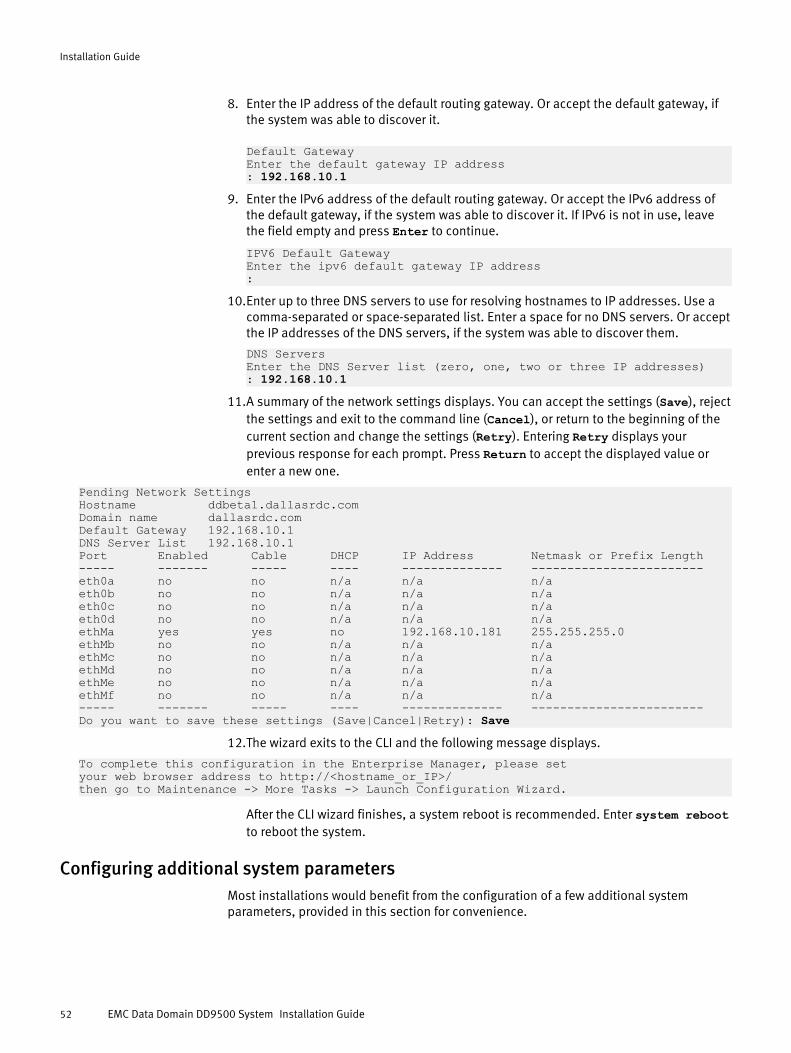
11.A summary of the network settings displays. You can accept the settings (Save), rejectthe settings and exit to the command line (Cancel), or return to the beginning of thecurrent section and change the settings (Retry). Entering Retry displays yourprevious response for each prompt. Press Return to accept the displayed value orenter a new one.
Pending Network SettingsHostname ddbeta1.dallasrdc.comDomain name dallasrdc.com Default Gateway 192.168.10.1 DNS Server List 192.168.10.1 Port Enabled Cable DHCP IP Address Netmask or Prefix Length----- ------- ----- ---- -------------- ------------------------eth0a no no n/a n/a n/a eth0b no no n/a n/a n/a eth0c no no n/a n/a n/a eth0d no no n/a n/a n/a ethMa yes yes no 192.168.10.181 255.255.255.0 ethMb no no n/a n/a n/a ethMc no no n/a n/a n/a ethMd no no n/a n/a n/a ethMe no no n/a n/a n/a ethMf no no n/a n/a n/a ----- ------- ----- ---- -------------- ------------------------Do you want to save these settings (Save|Cancel|Retry): Save
12.The wizard exits to the CLI and the following message displays.
To complete this configuration in the Enterprise Manager, please set your web browser address to http://<hostname_or_IP>/ then go to Maintenance -> More Tasks -> Launch Configuration Wizard.
After the CLI wizard finishes, a system reboot is recommended. Enter system rebootto reboot the system.
Configuring additional system parametersMost installations would benefit from the configuration of a few additional systemparameters, provided in this section for convenience.
Installation Guide
52 EMC Data Domain DD9500 System Installation Guide
Note
You can also use the EMC Data Domain (DD) System Manager GUI interface to configurethe system parameters. Open a web browser, and enter your Data Domain system’s IPaddress in the browser’s address text box. Log in when the DD System Manager loginscreen displays. Use the DD System Manager online help for more information.
Procedure
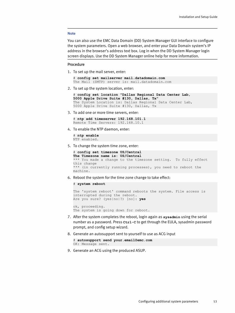
1. To set up the mail server, enter:
# config set mailserver mail.datadomain.comThe Mail (SMTP) server is: mail.datadomain.com
2. To set up the system location, enter:
# config set location "Dallas Regional Data Center Lab,5000 Apple Drive Suite #130, Dallas, Tx"The System Location is: Dallas Regional Data Center Lab,5000 Apple Drive Suite #130, Dallas, Tx
3. To add one or more time servers, enter:
# ntp add timeserver 192.168.101.1Remote Time Servers: 192.168.10.1
4. To enable the NTP daemon, enter:
# ntp enableNTP enabled.
5. To change the system time zone, enter:
# config set timezone US/CentralThe Timezone name is: US/Central*** You made a change to the timezone setting. To fully effect this change *** (in currently running processes), you need to reboot the machine.
6. Reboot the system for the time zone change to take effect:
# system reboot
The 'system reboot' command reboots the system. File access is interrupted during the reboot.Are you sure? (yes|no|?) [no]: yes
ok, proceeding.The system is going down for reboot.
7. After the system completes the reboot, login again as sysadmin using the serialnumber as a password. Press Ctrl-C to get through the EULA, sysadmin passwordprompt, and config setup wizard.
8. Generate an autosupport sent to yourself to use as ACG input
# autosupport send [email protected]: Message sent.
9. Generate an ACG using the produced ASUP.
Installation and Setup Guide
Configuring additional system parameters 53

Copyright © 2015 EMC Corporation. All rights reserved. Published in USA.
EMC believes the information in this publication is accurate as of its publication date. The information is subject to change withoutnotice.
The information in this publication is provided as is. EMC Corporation makes no representations or warranties of any kind withrespect to the information in this publication, and specifically disclaims implied warranties of merchantability or fitness for aparticular purpose. Use, copying, and distribution of any EMC software described in this publication requires an applicable softwarelicense.
EMC², EMC, and the EMC logo are registered trademarks or trademarks of EMC Corporation in the United States and other countries.All other trademarks used herein are the property of their respective owners.
For the most up-to-date regulatory document for your product line, go to EMC Online Support (https://support.emc.com).
Installation Guide
54 EMC Data Domain DD9500 System Installation Guide