emc electric throttle/cable shift installation and
TRANSCRIPT

EMC Electric Throttle/Cable Shift Installation and Operation Manual
Livorsi Part #
EMCPCF100
EMCPCF101
EMCPCF102
Revised June 2017
715 Center Street Grayslake IL 60030
P: 847-752-2700 F: 847-752-2415

Install/User Manual: EMC: LIT-CTL-EMC-REV0617 Page 2
TABLE OF CONTENTS
Introduction ..................................................................................................................................3
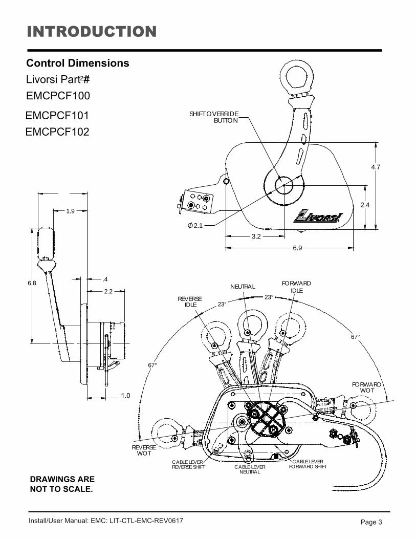
Control Dimensions ...................................................................................................................3
Installation ..................................................................................................................................4-5
Install Requirements........................ .........................................................................................4
Parts Included........ .................. ................................................................................................5
Maintenance ..................................................................................................................................7
Corrosion Protection ..................................................................................................................7
Mounting Templates ...................................................................................................................6
Warranty ........................................................................................................................................7
Using Mounting Templates / Cut Out Patterns ........................... .............................................4
Installing the Control .................. ...............................................................................................5
INTRODUCTION
Install/User Manual: EMC: LIT-CTL-EMC-REV0617 Page 3
Control Dimensions Livorsi Part # EMCPCF100
EMCPCF101 EMCPCF102
DRAWINGS ARE NOT TO SCALE.
3.2
6.9
4.7
2.1
2.4
SHIFT OVERRIDEBUTTON
23° 23°
67°
67°
NEUTRAL FORWARDIDLE
REVERSE IDLE
FORWARDWOT
REVERSEWOT
CABLE LEVERFORWARD SHIFTCABLE LEVER
NEUTRAL
CABLE LEVERREVERSE SHIFT
.4
1.9
2.2
2.8
6.8
1.0

Install Requirements
Magnetic interference: No speakers or magnetic sources within 12 inches of control.
INSTALLATIONUsing Mounting Templates / Cut Out PatternsUtilize the template provided for appropriate control cut out pattern. Template on page 7. Print template at 100% scale.
Repower / Replacement: Please note that installation of the Livorsi control may requiremodification of the existing control cut out pattern in your application. In some instances, an additional plate may need to be made to cover the old cutout to allow proper mounting of the new Livorsi control. Livorsi is not responsible for these modifications.
Install/User Manual: EMC: LIT-CTL-EMC-REV0617 Page 4

Install/User Manual: EMC: LIT-CTL-EMC-REV0617 Page 5
• Cable Pivot• Cotter Pin• Washer Flat
cotter pin washer
pivot
hex nut
Throttle Connector:
Make connections to the engine harnesses.When properly connected, you will hear a “click’, indicating a good connection.
Double check connection, by gently tugging at the connectors.
Installing the Control
Cable Clamp:
The cable clamp comes attached to the control base plate.
Slide the cable through the “U” shaped opening, and secure the cable in place by moving the latch to lock it in place.
Parts includedContents of small parts bag for base of control:
• Hex Nut• Set Screw for Bezel Plate
DEUTSCH DTM SERIESFEMALE RECEPTACLEPART# DTM04-6PCOLOR: GREY
THROTTLE CONNECTOR 1
23
654
CONNECTOR PIN-OUTSPIN 1 PPS1 +5v RefPIN 2 PPS2 +5v RefPIN 3 PPS1 SignalPIN 4 PPS1 GNDPIN 5 PPS2 GNDPIN 6 PPS2 Signal

INTENTIONALLY LEFT BLANK

MOUNTING TEMPLATE
Livorsi Part # EMCPCF100 EMCPCF101 EMCPCF102
Page 6
4 o f 5

INTENTIONALLY LEFT BLANK

MAINTENANCE
Corrosion Protection:
For maximum protection, especially in a saltwater environment, the control head and hand lever should be washed lightly with fresh water on a regular basis.
• Periodically check the control head mechanism for loose fasteners and signs of wear onmoving parts.
• Keep moving parts well lubricated with a moisture-displacing lubricant.• Periodically check the cables and engine connections for signs of wear and corrosion.
Replace as necessary.
WARRANTY
All Livorsi Marine® products carry a limited one year warranty for repair or replacement at Livorsi's discretion. All Livorsi Marine® products are warranted to be free of defects in material and workmanship. Users/Customers of Livorsi Marine®/Livorsi® products agree not to hold Livorsi Marine, Inc., its owner or employees responsible for any damages occurring by improper installation or use of Livorsi Marine® or Livorsi® products. The company, owner or its employees will not be liable for more than the cost of the original product and in no event will Livorsi Marine® or Livorsi® be liable for special, indirect or consequential damages of any kind whatsoever.
Install/User Manual: EMC: LIT-CTL-EMC-REV0617 Page 7

715 Center Street Grayslake IL 60030 P: 847-752-2700 F: 847-752-2415 E:[email protected]
Copyright © Livorsi Marine Inc.® All Rights Reserved.