elspec426bb82d2999c9147474-eae010336623170ce70309697b… · · 2013-03-26minimum voltage rating...
TRANSCRIPT


2 ELSPEC © GG44KK FFiixxeedd PPoowweerr QQuuaalliittyy AAnnaallyyzzeerr CCaalliibbrraattiioonn UUssiinngg TTeellnneett
Contents I. Introduction ...................................................................................................................................... 3
II. Calibration and Adjustment Procedure ............................................................................................ 3
III. Getting Started ................................................................................................................................. 4
IV. Voltage Calibration ........................................................................................................................... 5
IV.1 Voltage Neutral Calibration .................................................................................................... 6
IV.2 Voltage Phase Calibration ....................................................................................................... 9
V. Current Calibration ......................................................................................................................... 12
VI. Multi IO – Calibrating Analog Inputs & Outputs ............................................................................. 17
VII. PT 100 Temperature Calibration .................................................................................................... 20
3 ELSPEC © GG44KK FFiixxeedd PPoowweerr QQuuaalliittyy AAnnaallyyzzeerr CCaalliibbrraattiioonn UUssiinngg TTeellnneett
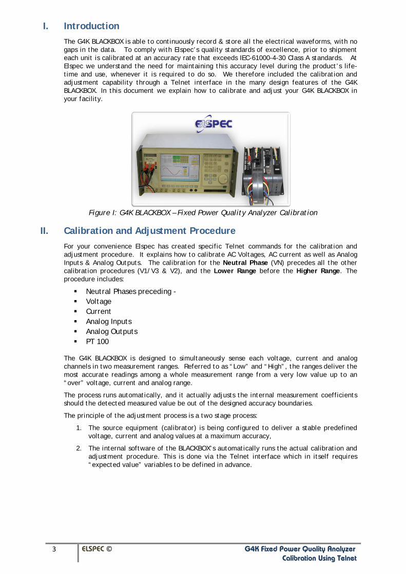
I. Introduction The G4K BLACKBOX is able to continuously record & store all the electrical waveforms, with no gaps in the data. To comply with Elspec’s quality standards of excellence, prior to shipment each unit is calibrated at an accuracy rate that exceeds IEC-61000-4-30 Class A standards. At Elspec we understand the need for maintaining this accuracy level during the product’s life-time and use, whenever it is required to do so. We therefore included the calibration and adjustment capability through a Telnet interface in the many design features of the G4K BLACKBOX. In this document we explain how to calibrate and adjust your G4K BLACKBOX in your facility.
Figure I: G4K BLACKBOX – Fixed Power Quality Analyzer Calibration
II. Calibration and Adjustment Procedure For your convenience Elspec has created specific Telnet commands for the calibration and adjustment procedure. It explains how to calibrate AC Voltages, AC current as well as Analog Inputs & Analog Outputs. The calibration for the Neutral Phase (VN) precedes all the other calibration procedures (V1/V3 & V2), and the Lower Range before the Higher Range. The procedure includes:
Neutral Phases preceding - Voltage Current Analog Inputs Analog Outputs PT 100
The G4K BLACKBOX is designed to simultaneously sense each voltage, current and analog channels in two measurement ranges. Referred to as “Low” and “High”, the ranges deliver the most accurate readings among a whole measurement range from a very low value up to an “over” voltage, current and analog range.
The process runs automatically, and it actually adjusts the internal measurement coefficients should the detected measured value be out of the designed accuracy boundaries.
The principle of the adjustment process is a two stage process:
1. The source equipment (calibrator) is being configured to deliver a stable predefined voltage, current and analog values at a maximum accuracy,
2. The internal software of the BLACKBOX’s automatically runs the actual calibration and adjustment procedure. This is done via the Telnet interface which in itself requires “expected value” variables to be defined in advance.
4 ELSPEC © GG44KK FFiixxeedd PPoowweerr QQuuaalliittyy AAnnaallyyzzeerr CCaalliibbrraattiioonn UUssiinngg TTeellnneett
The names and values of the parameters are defined by including them in brackets i.e.: {variable name or value}. The first step of each calibration procedure is to establish these variables. Then specific commands are applied to the variables to direct the specific calibration process. All other commands contained within these procedures are static and cannot be changed. Simultaneously, the correlating variable values are entered onto the calibrator itself in the “Waveform menu”. These values may differ according to the calibrator type that you are using. In this document Elspec is using a standard signal generator.
III. Getting Started Prepare the following items in advance, before you start the procedure:
G4K BLACKBOX Fixed PQA that needs to be calibrated
Voltage Block Connector with Connections
Current Connections
If Multi IO is present:
Analog Input Connections
Analog Output Connections
PT100 Sensor
Calibration Instrument: You may use any device that measures up to the IEC standards, with a minimum voltage rating of 1000 volts, and current output of at least 20A).
You now need to connect the G4K unit via TELNET:
On your computer select from the Start Menu: StartRun:telnet(UnitIP)
Enter User Name: PQ4xx
Enter Password: PQ4xxPQ4xx
For your convenience, you may also find the unit’s IP via Elspec Search (according to the unit’s serial number).
You will now need to connect the G4K BLACKBOX to the calibration instrument with the relevant cables (for each calibration category).
Set the following configurations on your BLACBOX unit:
Frequency – the Nominal frequency should be 50/60Hz according to your calibrator frequency
Topology - Wye 4 wire PT and CT – disable all PT’s and CT’s Ratios

5 ELSPEC © GG44KK FFiixxeedd PPoowweerr QQuuaalliittyy AAnnaallyyzzeerr CCaalliibbrraattiioonn UUssiinngg TTeellnneett
IV. Voltage Calibration In order to maximize the calibration accuracy for the device, we recommend establishing Low and High voltage ranges to calibrate the voltage inputs. Use values 300V and 750V respectively. All Phase voltages are calibrated referring to Neutral and the Neutral terminal, and it is calibrated with reference to the Earth. In order to rely on the accuracy of the phase voltage calibration, you will need to first calibrate the Neutral input.
Open the Monitoring page on the web interface of the BLACKBOX unit, in order to simultaneously monitor the Voltage & Current RMS, and Waveforms during each step of the calibration process:
1. Open the Elspec’s Search Utility & locate your BLACKBOX via the devices’ serial number, and access your device via the WEB.
Figure 2: Access via Elspec Search
2. Login to the Internal Website as the Administrator select “Login”:
Figure 3: Internal Website – Login Administrator
3. Open the “Monitoring” Tab select “Voltage & Currents” option:
Figure 4: Internal Website – Monitoring Voltage & Current Page

6 ELSPEC © GG44KK FFiixxeedd PPoowweerr QQuuaalliittyy AAnnaallyyzzeerr CCaalliibbrraattiioonn UUssiinngg TTeellnneett
4. Alternatively switch to Waveform page. Select “Monitoring”, “Waveforms”:
Figure 5: Internal Website – Monitoring Waveforms Page
IV.1 Voltage Neutral Calibration
The following procedure will demonstrate how to perform both a Low and High Voltage Neutral Voltage Calibration. Repeat the procedure twice: once for the Low voltage and once for the High voltage.
NOTE NOTE NOTE Every time you calibrate the Low value, you will need to calibrate the High value. Ensure that you work on an official Telnet version. The Ground input is the reference for all channels therefore it is essential to connect
it properly.
Calibrating the Voltage Neutral Voltage Low:
1. The G4K’s Voltage Inputs are located on the DSP Module. They are marked as L1, L2, L3, N, & . The phases are connected via the Voltage Terminal Block Connector provided with the G4K Unit:
Figure 6a: G4K Voltage Inputs DSP Module Figure 6b: G4K Voltage Terminal Block Connector
2. In order to calibrate Voltage Neutral, you will need to connect any of the Phases (1/2/3) & Ground. As per Fig 7 attach lugged ends of the lines to the terminal block securing it with an applicable sized screw driver:
L1 – L3,
- L2,
N – N
Insert the terminal block into the Voltage Input of the DSP Module:
Figure 7: G4K Voltage Neutral Connection

7 ELSPEC © GG44KK FFiixxeedd PPoowweerr QQuuaalliittyy AAnnaallyyzzeerr CCaalliibbrraattiioonn UUssiinngg TTeellnneett
3. Set the Signal Calibrator Voltage at 300V RMS
4. Connect the relevant cables to the calibration instrument.
5. In the Telnet menu define and set the parameters. The Telnet format reads as follows:
{variable name}=(float)value
6. Define the low voltage parameter by entering:
VLow=(float)300
Figure 8: VLow Value Assignment
7. Initiate the Low Neutral Voltage Calibration by entering:
CalibrateVoltageNeutralLow VLow
Figure 9: Calibration of the Low Neutral Voltage Command
NOTE NOTE NOTE
Each calibration step will take a few minutes. Please be patient until you receive the “Calibration success, results…” message
This will be followed by a success screen confirming Low Range Neutral Voltage calibration:
Figure 10: Calibration Success
8 ELSPEC © GG44KK FFiixxeedd PPoowweerr QQuuaalliittyy AAnnaallyyzzeerr CCaalliibbrraattiioonn UUssiinngg TTeellnneett
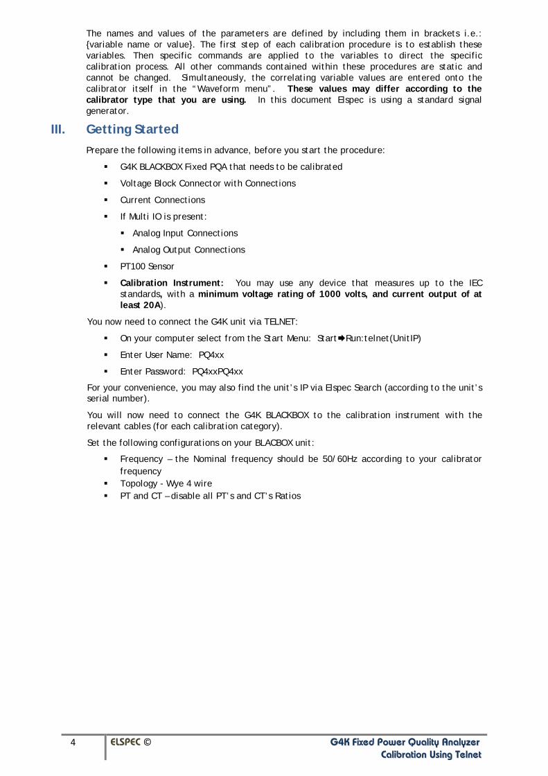
Prior to calibrating the Neutral Voltage High, ensure that the Voltage has stabilized as per the G4K’s Web Interface. Calibrate the Neutral Voltage High:
1. Once again set the Signal Generator Voltage at 750V RMS
2. In the Telnet menu define the high voltage parameter by entering:
VHigh=(float)750
Figure 11: VHigh Value Assignment
3. Initiate the High Neutral Voltage Calibration by entering:
CalibrateVoltageNeutralHigh VHigh
Figure 12: Calibration of the High Neutral Voltage Command
This will be followed by a success screen confirming High Range Neutral Voltage calibration:
Figure 13: Calibration Success

9 ELSPEC © GG44KK FFiixxeedd PPoowweerr QQuuaalliittyy AAnnaallyyzzeerr CCaalliibbrraattiioonn UUssiinngg TTeellnneett
IV.2 Voltage Phase Calibration
Once the Neutral has been calibrated, you will need to calibrate the phase voltages for both the Low and High values. All the phases L1,
NOTE NOTE NOTE
L2 and L3 are calibrated simultaneously. As in the Neutral calibration procedure, Phase calibration is performed in two separate steps; first the Low Voltages followed by the High Voltages. The variable names can inherit old values for each procedure therefore it is not required to establish new variables.
Every time you calibrate the Low value, you will need to calibrate the High value. Ensure that you work on an official Telnet version. The Ground input is the reference for all channels therefore it is essential to connect
it properly.
1. In order to calibrate the phases, you will need to disconnect the Voltage Neutral. Do not disconnect the Ground. Attach lugged ends of L1, L2 & L3 lines to the terminal block securing it with an applicable sized screw driver. Insert the terminal block into the Voltage Input of the DSP Module:
Figure 14a: L1, L2, L3 & Voltage Connection
Figure 14b: Terminal Block Connector Connected to the G4K BLACKBOX
2. Set the Signal Calibrator Voltage at 300V RMS
3. Connect the relevant cables to the calibration instrument.
4. As you have already defined the High & Low voltage parameters in the Telnet menu during the Neutral phase calibration, the Telnet memory will recall these values. It is not therefore necessary to reset these values again. Directly initiate the simultaneous V0,V1,V2 & V3 low range calibration by entering the following command:
CalibrateVoltagesLow (VLow)
Figure 15: Calibration of the Low Range Voltages Command

10 ELSPEC © GG44KK FFiixxeedd PPoowweerr QQuuaalliittyy AAnnaallyyzzeerr CCaalliibbrraattiioonn UUssiinngg TTeellnneett
When all phases will be completed, it will be followed by a success screen confirming the calibration for the Low Range Voltages:
Figure 16: Calibration Success for the Low Range Phase Voltages
5. Prior to calibrating the Voltage High, ensure that the Voltage has stabilized as per the G4K’s Web Interface. Set the Signal Generator Voltage at 750V RMS
6. Repeat the process for the simultaneous high range calibration V0,V1,V2 & V3 by entering a entering the following command on the Telnet screen:
CalibrateVoltagesHigh (VHigh)
Figure 17: Calibration of the High Range Voltages Command
11 ELSPEC © GG44KK FFiixxeedd PPoowweerr QQuuaalliittyy AAnnaallyyzzeerr CCaalliibbrraattiioonn UUssiinngg TTeellnneett
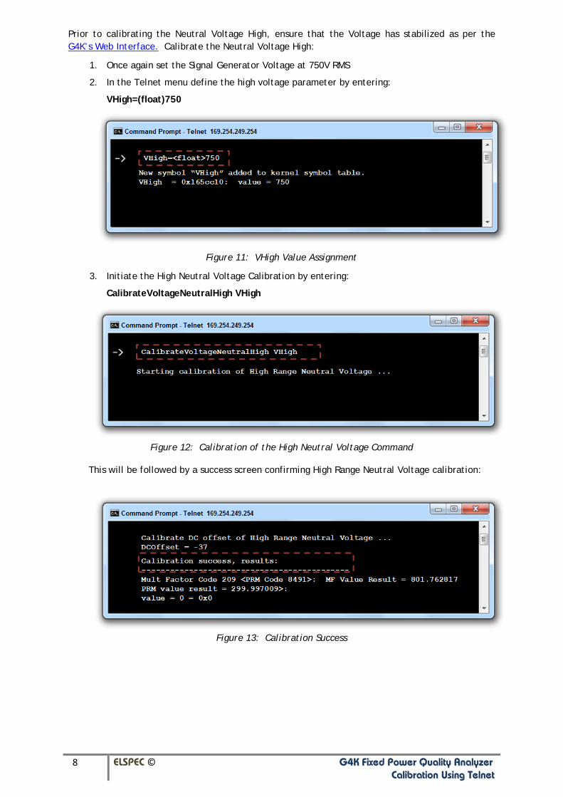
When all phases will be completed, it will be followed by a success screen confirming the calibration for the High Range Voltages:
Figure 18: Calibration Success for the High Range Phase Voltages

12 ELSPEC © GG44KK FFiixxeedd PPoowweerr QQuuaalliittyy AAnnaallyyzzeerr CCaalliibbrraattiioonn UUssiinngg TTeellnneett
V. Current Calibration Elspec calibrates the current inputs by injecting the voltage and current simultaneously. The voltage channel reading is required for PLL synchronization, and therefore you will need to connect at least one voltage phase during the “current calibration” procedure as outlined below. The calibration for the G4K’s current channels is done simultaneously for all the channels (I1, I2, I3 and IN). As in the Voltage calibration procedure, Current calibration is performed in two separate steps; first for the Low Current Range (3.0A) followed by the High Current Range (9.0A). Prior to initiating the calibration procedure, you will need to reconfigure your G4K’s Current Transformer (CT) ratios to read as a duplicate ratio – i.e.: 50:50. The configuration is done in Elspec’s website.
The G4K’s current channels are connected through the cylindrical apertures that are located on the circular section of the centrally mounted Digital Signal Processing (DSP) Module. There are a total of six (6) apertures. The calibration procedure outlines the calibration for the first four (4) apertures that are used as current inputs for I1, I2, I3, and IN. If you ordered the fifth optional aperture for an additional current input, ensure that you simply connect the fifth current cable to both the G4K & the calibration instrument. The sixth aperture is disabled at this stage.
1. Ensure that 1 of the Voltage Phases on the Voltage block remains connected
2. Feed the current cables through the apertures as per figure 19 below:
Figure 19: G4K BLACKBOX Current Connection
I1
I
through Aperture 1
2
I
through Aperture 2
3
I
through Aperture 3
N
through Aperture 4

13 ELSPEC © GG44KK FFiixxeedd PPoowweerr QQuuaalliittyy AAnnaallyyzzeerr CCaalliibbrraattiioonn UUssiinngg TTeellnneett
3. Open the Elspec’s Search Utility & locate your BLACKBOX via the devices’ serial number, and access your device via the WEB.
Figure 20: Access via Elspec Search
4. Login to the Internal Website as the Administrator select “Login”:
Figure 21: G4K Website – Login Administrator
5. Open the “Configuration” Tab select “Currents” option:
Figure 22: G4K Website – Currents Configuration Access
6. The Current Configuration Window will now open. Set the correct Primary & Secondary Transformation Ratios for all the Current channels from I1 to IN
(with / ) to duplicate values:
Figure 23: G4K Website – CT Ratios

14 ELSPEC © GG44KK FFiixxeedd PPoowweerr QQuuaalliittyy AAnnaallyyzzeerr CCaalliibbrraattiioonn UUssiinngg TTeellnneett
7. To apply your changes select
8. Connect the relevant current cables to the calibration instrument.
9. Set the calibration instrument to 3.0A
10. In the Telnet menu define and set the parameters. The Telnet format reads as follows:
{variable name}=(float)value
11. Define the low voltage parameter by entering:
ILow=(float)3
Figure 24: ILow Value Assignment
12. Directly initiate the simultaneous I0,I1,I2,I3 & IN low range calibration by entering the following command:
CalibrateCurrentsLow (ILow)
Figure 25: Calibration of the Low Range Currents Command
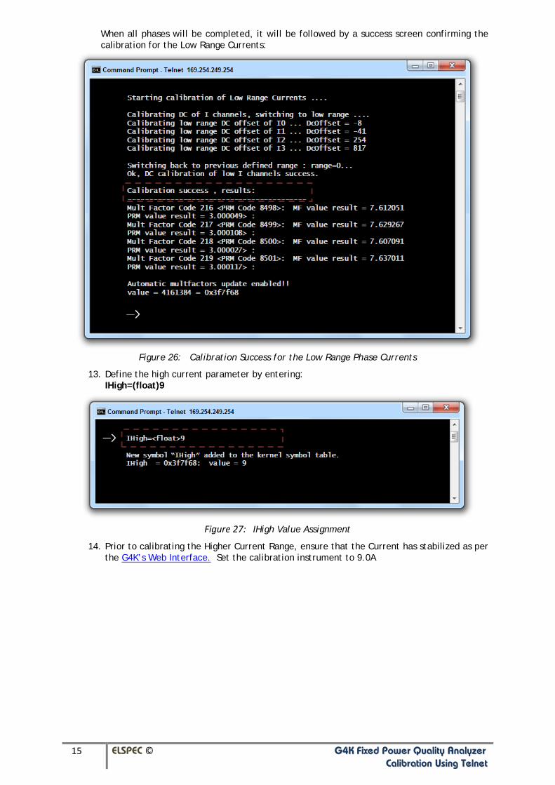
15 ELSPEC © GG44KK FFiixxeedd PPoowweerr QQuuaalliittyy AAnnaallyyzzeerr CCaalliibbrraattiioonn UUssiinngg TTeellnneett
When all phases will be completed, it will be followed by a success screen confirming the calibration for the Low Range Currents:
Figure 26: Calibration Success for the Low Range Phase Currents
13. Define the high current parameter by entering: IHigh=(float)9
Figure 27: IHigh Value Assignment
14. Prior to calibrating the Higher Current Range, ensure that the Current has stabilized as per the G4K’s Web Interface. Set the calibration instrument to 9.0A

16 ELSPEC © GG44KK FFiixxeedd PPoowweerr QQuuaalliittyy AAnnaallyyzzeerr CCaalliibbrraattiioonn UUssiinngg TTeellnneett
15. As with the low range, repeat the process for the simultaneous high range calibration I0,I1,I2 & I3 by entering the following command on the Telnet screen: CalibrateCurrentsHigh (IHigh)
Figure 28: Calibration of the High Range Currents Command
When all phases will be completed, it will be followed by a success screen confirming the calibration for the High Range Currents:
Figure 29: Calibration Success for the High Range Phase Currents
17 ELSPEC © GG44KK FFiixxeedd PPoowweerr QQuuaalliittyy AAnnaallyyzzeerr CCaalliibbrraattiioonn UUssiinngg TTeellnneett
VI. Multi IO – Calibrating Analog Inputs & Outputs
This chapter is applicable only if your G4K BLACKBOX is equipped with a Multi IO Module. On the Multi IO you will need to calibrate only the Analog Inputs & Outputs. The Analog Connector is divided into the two connected sections. In contrary to preceding the previous calibration procedures, once you enter the Telnet command the Telnet will automatically recognize the Lower Analog Range (4mA) & Higher Analog Range (20mA). During the initial stage you will connect the Analog Inputs & calibrate accordingly. As soon as this calibration is completed, the Telnet will automatically prompt you to connect the Analog Outputs & to proceed with the calibration.
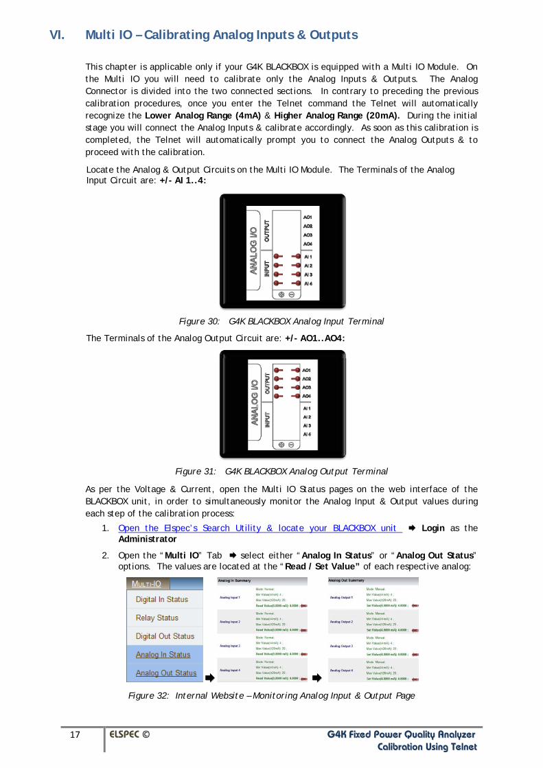
Locate the Analog & Output Circuits on the Multi IO Module. The Terminals of the Analog Input Circuit are: +/- AI 1..4:
Figure 30: G4K BLACKBOX Analog Input Terminal
The Terminals of the Analog Output Circuit are: +/- AO1..AO4:
Figure 31: G4K BLACKBOX Analog Output Terminal
As per the Voltage & Current, open the Multi IO Status pages on the web interface of the BLACKBOX unit, in order to simultaneously monitor the Analog Input & Output values during each step of the calibration process:
1. Open the Elspec’s Search Utility & locate your BLACKBOX unit Login as the Administrator
2. Open the “Multi IO” Tab select either “Analog In Status” or “Analog Out Status” options. The values are located at the “Read / Set Value” of each respective analog:
Figure 32: Internal Website – Monitoring Analog Input & Output Page

18 ELSPEC © GG44KK FFiixxeedd PPoowweerr QQuuaalliittyy AAnnaallyyzzeerr CCaalliibbrraattiioonn UUssiinngg TTeellnneett
Calibrating the Analog Inputs & Outputs:
1. Set the calibration instrument to 4mA
2. Enter the Analog Calibration command in the Telnet menu:
Manuf_AnalogIO_Calibrate
Figure 33: Analog IO Calibration
3. At the prompt connect the Analog Input Connector into the Analog Input Terminal & type C on your keyboard:
Figure 34: Analog Input Calibration Low Range Prompt – 4mA
4. Prior to calibrating the Higher Range of the Analog Input, ensure that all the channels have stabilized via the web interface of the G4K. Set the calibration instrument to 20mA
5. At the prompt type C on your keyboard:
Figure 35: Analog Input Calibration High Range Prompt – 20mA

19 ELSPEC © GG44KK FFiixxeedd PPoowweerr QQuuaalliittyy AAnnaallyyzzeerr CCaalliibbrraattiioonn UUssiinngg TTeellnneett
The Analog Output Connector that is supplied with the G4K Multi IO Module:
Figure 36: G4K BLACKBOX Analog Output Connector
6. As mentioned previously, monitor the Analog Input status as per the web interface of the G4K unit. At the prompt connect the Analog Output Connector into the Analog Output
Terminal (Fig.36 above) & type C on your keyboard:
Figure 37: Analog Output Calibration Prompt
7. The process will now automatically run for both the Analog Output High & Low Range. You will receive a success message when completed:
Figure 38: Calibration Success for the Analog Output Channels
20 ELSPEC © GG44KK FFiixxeedd PPoowweerr QQuuaalliittyy AAnnaallyyzzeerr CCaalliibbrraattiioonn UUssiinngg TTeellnneett
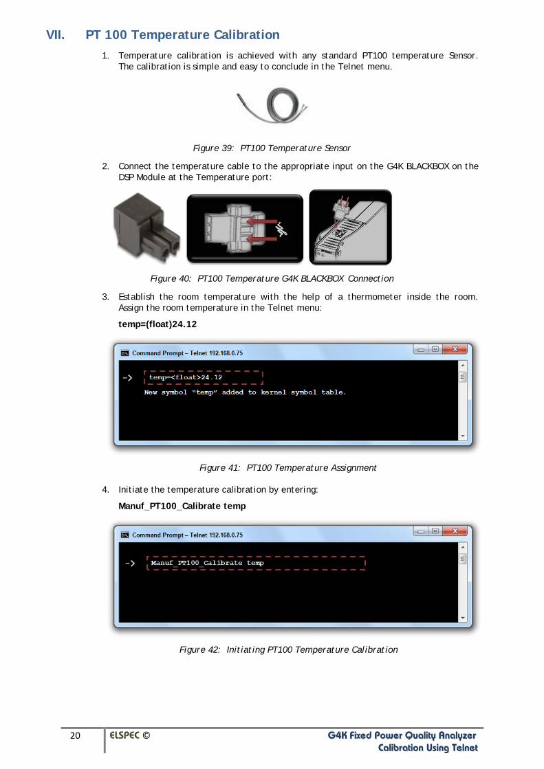
VII. PT 100 Temperature Calibration 1. Temperature calibration is achieved with any standard PT100 temperature Sensor.
The calibration is simple and easy to conclude in the Telnet menu.
Figure 39: PT100 Temperature Sensor
2. Connect the temperature cable to the appropriate input on the G4K BLACKBOX on the DSP Module at the Temperature port:
Figure 40: PT100 Temperature G4K BLACKBOX Connection
3. Establish the room temperature with the help of a thermometer inside the room. Assign the room temperature in the Telnet menu:
temp=(float)24.12
Figure 41: PT100 Temperature Assignment
4. Initiate the temperature calibration by entering:
Manuf_PT100_Calibrate temp
Figure 42: Initiating PT100 Temperature Calibration

21 ELSPEC © GG44KK FFiixxeedd PPoowweerr QQuuaalliittyy AAnnaallyyzzeerr CCaalliibbrraattiioonn UUssiinngg TTeellnneett
5. Calibration Success will now be confirmed:
Figure 43: Calibration for PT100 Temperature Successful