elimination of heterodyne interferometer nonlinearity by carrier
TRANSCRIPT
Elimination of Heterodyne Interferometer Nonlinearity by Carrier Phase Modulation
Work done by Serge Dubovitsky, Oliver P. Lay, and David J. Seidel Jet Propulsion Laboratory, California Institute of Technology
Pasadena, California
To be presented by Peter Halverson at the National Research Laboratory of Metrology
Tsukuba, Japan April 3,2001
JPL Motivation and Outline
I
~ ~~
Motivation - JPL’s Space Technology 3 (ST3) mission requires inter-spacecraft linear
metrology: Performance: 11 nanometers at 1 kilometer Implementation: heterodyne interferometer laser gauge
- Problem: Cyclic Nonlinearity due to Polarization Leakage in heterodyne interferometers ST3 operating conditions are such that existing methods of cyclic nonlinearity suppression could not be used
- Solution Novel methad: Heterodyne Interferometer with Carrier Phase Modulation
Outline - Concept - Proof-of-concept experiments - Analysis of operation and limitations
I
f
3116101
q4 Phase Meter
AL PMMetmbgy-3
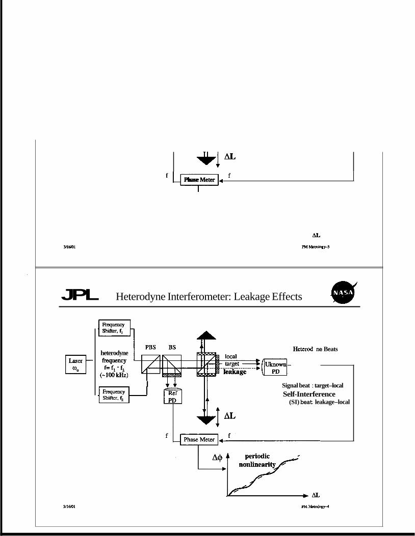
JPL Heterodyne Interferometer: Leakage Effects
heterodyne frequency f= fi - fi
(-100 kHz)
Heterod ne Beats
(-1 I 4 4 Signal beat : target-local
Self-Interference (SI) beat leakage-local
PM M2tmlogy-4
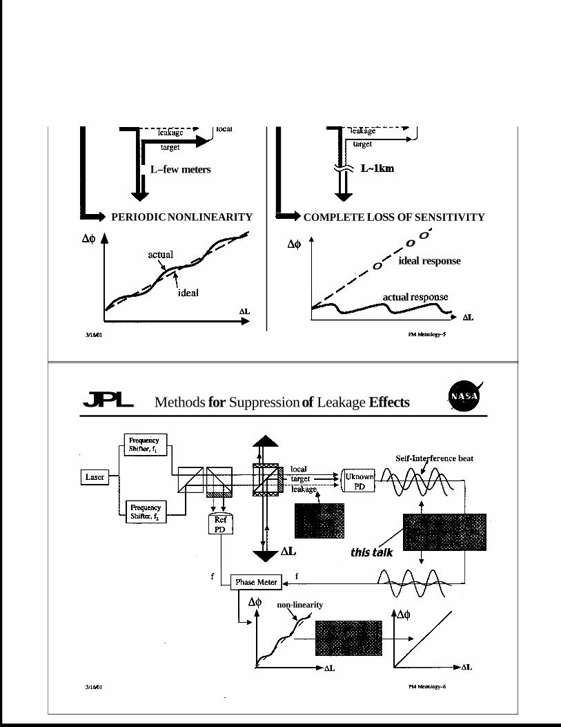
L-few meters
e PERIODIC NONLINEARITY COMPLETE LOSS OF SENSITIVITY
A@ T 0
0 ideal response
0 /
0
0 - actual .response
J b A L
JPL Methods for Suppression of Leakage Effects
? Self-Intefference beat
f
non-linearity
3116101
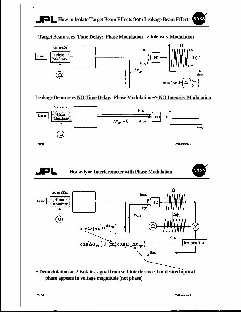
JpL How to Isolate Target Beam Effects fiom Leakage Beam Effects
Target Beam sees Time Delay: Phase Modulation -> Intensitv Modulation
I t time
m = 2A@sin(Oh7')
Leakage Beam sees NO Time Delay: Phase Modulation -> NO Intensitv Modulation
Homodyne Interferometer with Phase Modulation
Demodulation at C2 isolates signal from self-interference, but desired optical phase appears in voltage magnitude (not phase)
3I16KJ1 PM MCmlogy-8

JPL Heterodyne Interferometer + Phase Modulation QU ” A+ cos(Qt) shifter, f, - -
Laser Modulator uo
Phase - -
s, = A(L,Q,qw) Sh[ f t + ( 0 0 + f&L] Amplitude f -
Heterodyne optical phas frequency
Demodulation at &I isolates signal fkom self-interference, AND desired optical phase appears as phase of the heterodyne beat
u16101 p”etro”9
JPL Heterodyne Interferometer with a Phase Modulated Source
U k n O W n
Electronics
Heterodyne Interferometer Operation Self-Interference is suppressed
PM Metrology10
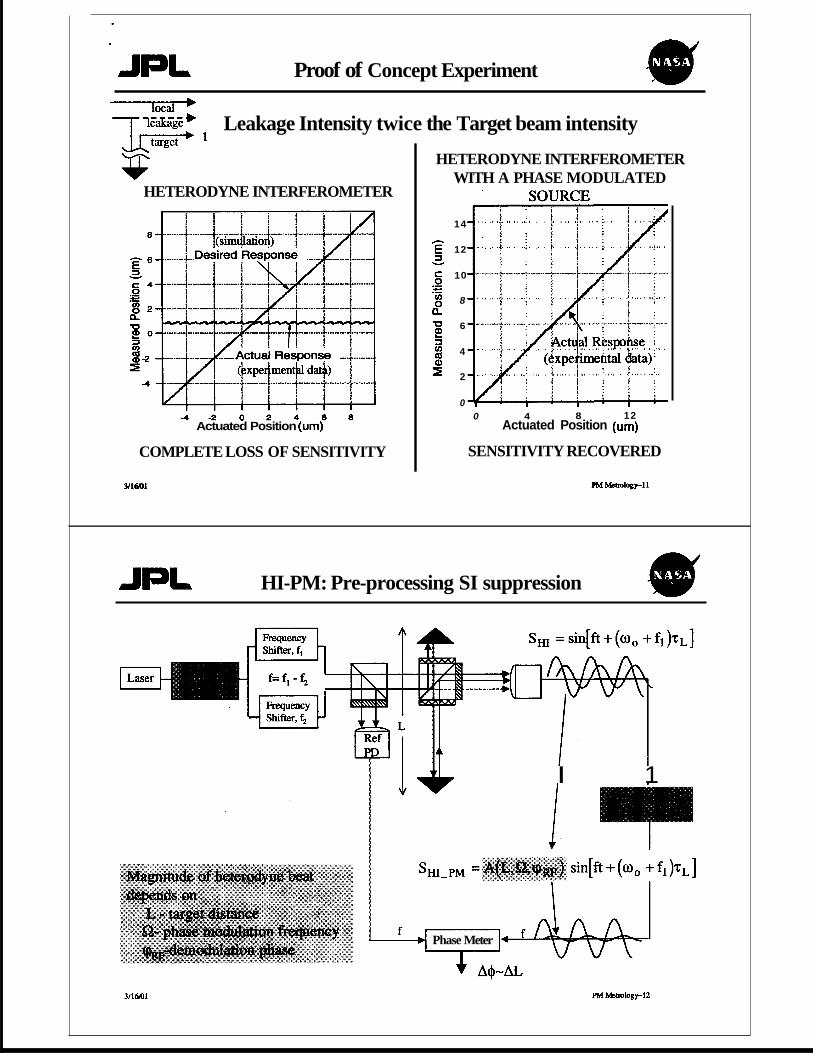
Proof of Concept Experiment
v HETERODYNE INTERFEROMETER
- 4 - 2 0 2 4 6 8 Actuated Position (urn)
COMPLETE LOSS OF SENSITIVITY
HETERODYNE INTERFEROMETER WITH A PHASE MODULATED
Leakage Intensity twice the Target beam intensity
14
12
10
8
6
4
2
0 0 4 8 12
Actuated Position (urn)
SENSITIVITY RECOVERED
3/16Kt1
HI-PM: Pre-processing SI suppression
I 1
Phase Meter
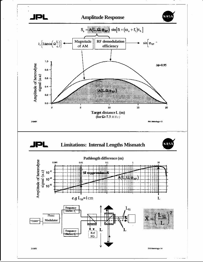
Amplitude Response
J 1
Y
RF demodulation I + ,in[qw +
efficiency
leO 1 A4d.95
0 5 10 15 20
Target distance L (m) (for e 7 . 5 M H z )
Limitations: Internal Lengths Mismatch
0.001
Pathlength difference (m) 0.01 0.1 1 10
1-y Phase Modulator
311601
e.g L,=l cm L
PM Wt1~10gy-14
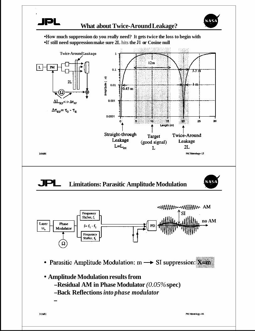
What about Twice-Around Leakage? .How much suppression do you really need? It gets twice the loss to begin with *If still need suppression make sure 2L hits the J1 or Cosine null
Twice-Around Leakage n J
1
0.1
h
? v
8 0.01 .- a E" a -
0.001
0 . m 1
3/16@1
JPL Limitations: Parasitic Amplitude Modulation
AM
no AM +
Amplitude Modulation results from -Residual AM in Phase Modulator (0.05% spec) -Back Reflections into phase modulator
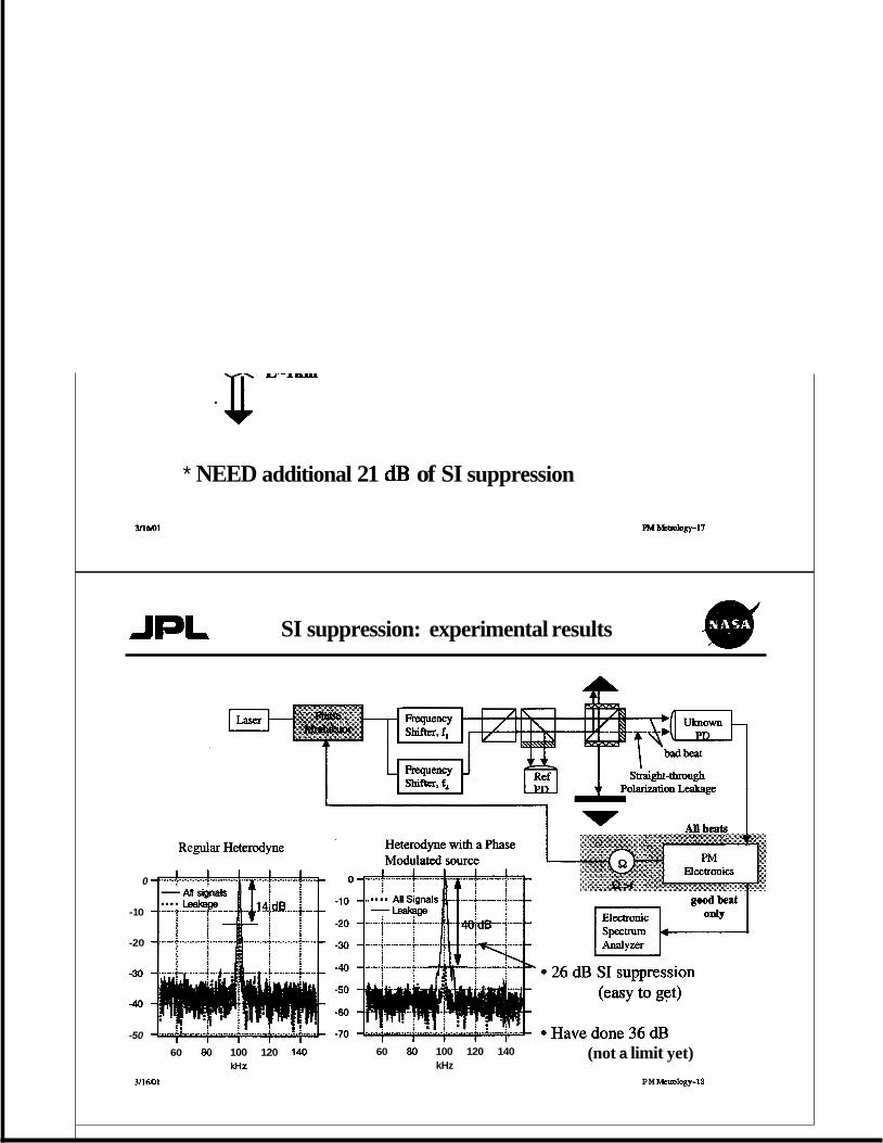
* NEED additional 21 dB of SI suppression
SI suppression: experimental results
0
-1 0
-20
-30
-40
-50
60 80 100 120 140 WZ
3116101
60 80 100 120 140 kHz
(not a limit yet) PM Memlogy-18
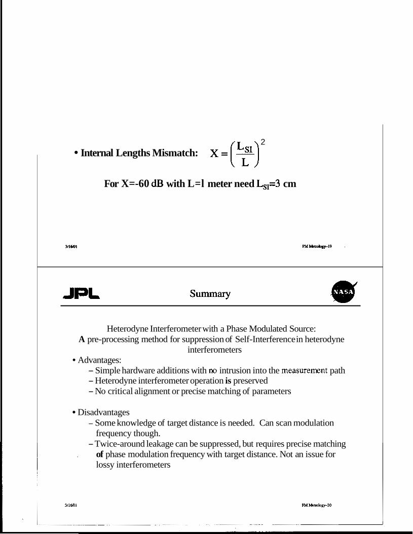
2 Internal Lengths Mismatch: x = (F)
For X=-60 dB with L=l meter need L,,=3 cm
summary
Heterodyne Interferometer with a Phase Modulated Source: A pre-processing method for suppression of Self-Interference in heterodyne
interferometers
- Simple hardware additions with no intrusion into the measurement path - Heterodyne interferometer operation is preserved - No critical alignment or precise matching of parameters
Advantages:
Disadvantages - Some knowledge of target distance is needed. Can scan modulation
- Twice-around leakage can be suppressed, but requires precise matching frequency though.
. of phase modulation frequency with target distance. Not an issue for lossy interferometers
3116r01 PM Metmlogy-20
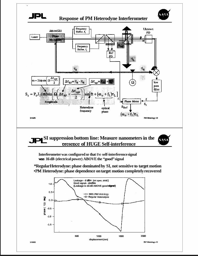
JpL Response of PM Heterodyne Interferometer 4r
3/16@1
4
JPL SI suppression bottom line: Measure nanometers in the mesence of HUGE Self-interference
Interferometer was configured so that the self-interference signal was 16 dB (electrical power) ABOVE the “good” signal
*Regular Heterodyne: phase dominated by SI, not sensitive to target motion *PM Heterodyne: phase dependence on target motion completely recovered
1 .o
0.5
h CI)
% 0.0 8 l- - -0.5 t r 9.
-1 .o
-1.5
~~~~ ~~ ~ ~~ ~
Leakage- -8 dBm (on spec. anal.) Good signal- -24dBm (Leakage is 16 dB ABOVE good dgnal)
+ With PM Metrology +Regular Heterodyne
500 lo00 1500 displacement (nm)
2000
PM Memlogy-22
1 ) b
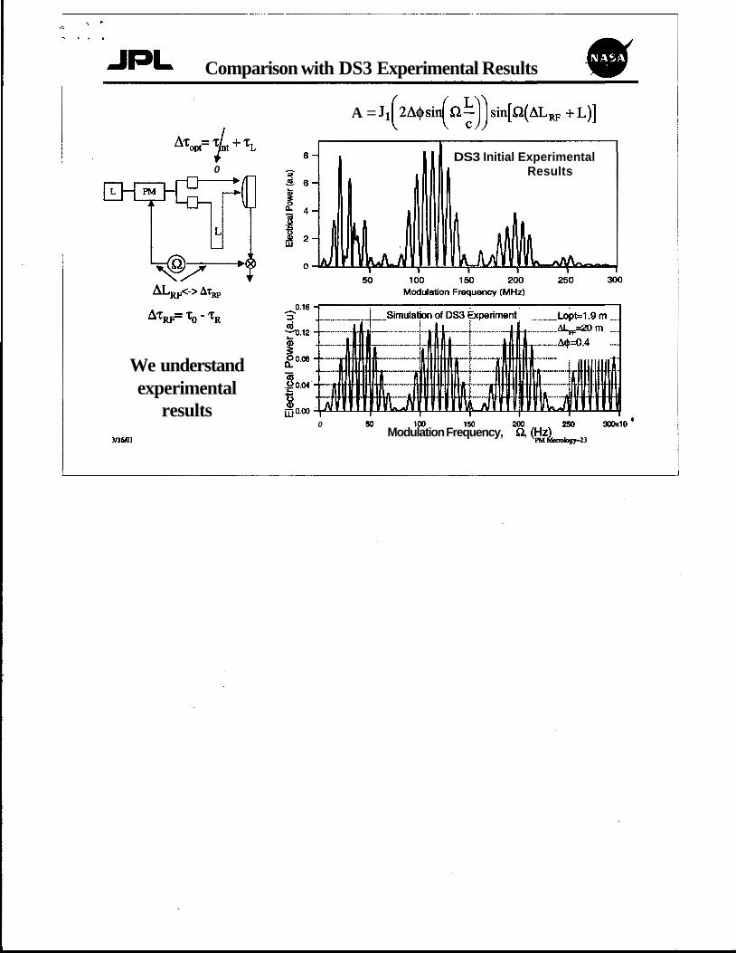
JpL Comparison with DS3 Experimental Results
* 0
We understand experimental
results 316m
A = J1 2Aesin In-" sin[Q(ALw +L)] ( ( 5)) DS3 Initial Experimental
Results
I I I I I
0 50 100 150 200 250 300x10 e Modulation Frequency, Q,
JET PROPULSION LABORATORY INTEROFFICE MEMORANDUM
To: Document Review
Subject: Author Certification for Oral PresentationPoster Session Paper
Title of Abstract for PresentationPoster Session Paper:
Elimination of Heterodyne Interferometer Nonlinearity
by Carrier Phase Modulation
ConferenceMeeting:
Invited Talk d
National Research Laboratory of Metrology
Date(s)/hation:
April 03, 2001, Tsukuba, Japan
This is a request that the abstract named above be used to clear the oral presentatiodposter session paper that will be given at the conference/meeting and date/location shown above.
I certify the following:
If this presentatiodposter session paper is to be published in any way (including conference proceedings and handouts), I will submit the fill-text version of it for clearance prior to publication. I understand that clearance based on an abstract is for an oral presentatiodposter session paper only. Only the abstract, as cleared, may be published based on this clearance.
The presentatiodposter session paper will accurately present the relationship among JPL, Caltech, and NASA, and will accurately present the funding source.
The presentatiodposter session paper will accurately credit work originated by non-JPL authors or from other sources.
Author Certification for Oral Presentatiofloster Session Paper JPL 2785 10/2000 Page 1

The presentatiodposter session paper will NOT:
Describe technology, including devices or methods or computer programs, except what has already been specifically reported in the open literature, in a JPL document that has been cleared for external release (Clearance Number ), or in New Technology Report (NTR) NQO - 207 90 . Reveal software code or classified, proprietary, discreet, or patentable information. (This information may include budget and cost data, nuclear power, implementation plans related to planetary protection requirements, and implementation plans for sample-return Earth landing sites.) Endorse vendor products or services. Contain statements that might adversely affect the image or reputation of JPL, Caltech, NASA, or other sponsor. Contain statements with national, international, or interagency political implications. Contain personal aggrandizement. Contain errors (content, language, or formatting) potentially embarrassing to JPL, Caltech, NASA, or other sponsor.
This abstract accurately represents the content of the oral presentatiodposter session paper to follow. The oral presentatiodposter session paper will meet the requirements defined in the policy Releasing Information Outside of JPL and the procedure Releasing Information for External Distribution, both of which I have read and understand. If I substantively change the content of the oral presentatiodposter session paper such that this abstract no longer accurately represents its content, I will notie Document Review and submit an updated abstract for clearance before the oral presentatiodposter session paper is given. By signing my name to this statement, I understand that I am assuming responsibility for any consequences resulting fiom my inappropriate disclosure of information outside JPL.
I will retain a copy of the final presentatiodposter session paper for one year after the date of the conference/meeting listed at the beginning of this memo and will make it available for compliance reviews if requested.
Dr. Peter G. Halverson Print Name
Sign Name Date
Author Certification for Oral PresentationPoster Session Paper JPL 2785 10/2000 Page 2
I C
L
Jet Propulsion Laboratory California lnstitute of Technology 4800 Oak Grove Drive Pasadena, Cali fomia 9 1 I 09-8099, (8 1 Ow4432 I
JPL
February 16,2001
Dr. Serge Dubovitsky
Refi NASA Tech Brief NPO-20740 HETERODYNE INTERFEROMETER W T H PWSE-MODULATED CARRIER
Congratulations on your Tech Briefwhich was published in the 02/01/2001 issue of the %?ASA Tech Briefs journal. We appreciate your collaboration with the Technology Utilization Program; please continue to support the program and encourage othgrs to participate.
The enclosed Technical Support Package was prepared by this ofice to send to those individuals who request additional information on your Tech Brief: Please inform this ofice of any additional material which you want added to this package to help indust?y create new products, processes or services based on your work.
V e v truly yours.
&& James A. Rooney Deputy Manager Commercinl Technolow Program
Enclostrres: d s
xc: (dTech Brief only) Emploevee Records, T-I 720-C
NATIONAL AERONAUTICS ABD SPACE ADiWNlSTR~TIO~ CONTRACT NO. NAS 7-918 #
TECHNICAL SUPPORT PACKAGE
I HETERODYNE INTERFEROLMETER WITH PHASE-MODULATED I
Inventor(s):
Serge Dubovitsky
TSP assembled bv: JPL Technology Reporting Office
pp. i-ii, 1-3
for February 01
NASA TECH BRIEF Vol. IS, No. 2. Item #
. from
JPL NEW TECHNOLOGY REPORT WO-20740
NOTICE i i Neither the United States Government, nor i ; NASA:
i a. Makes any warranty or representation, i express or implied, with respect of the i
i accuracy, completeness, or usefulness of the I information contained in this document, or that ! the use of any information, apparatus, 1 method. or process disclosed in this
NASA, nor any person acting on behalf of i
i
I document may not infringe priMtely owned ! i
b. Assumes any liabilities with respect to the ! I use of, or for damages resulting from the use i : of, any information, apparatus, method or f process disclosed in this document.
.JET P R O P U L S I O N L A B O R A T O R Y C A L I F O R N I A I N S T I T U T E O F T E C H S O L O G Y
P . A S . , D E I \ i A , C A L I F O R N 1 . 4
February 01
Reference Photodetector
I I Mixer I I (n?
W
Bandpass at f
f
v
1
+
i

. ~ ii
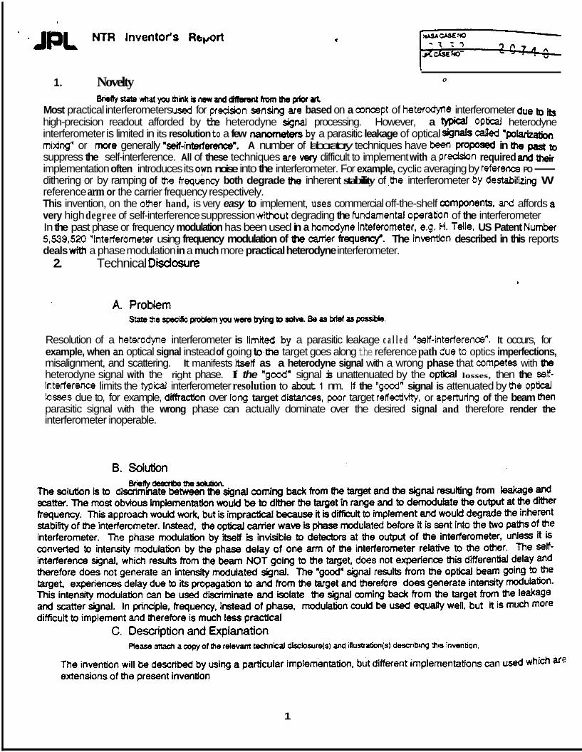
1. Novelty I
0
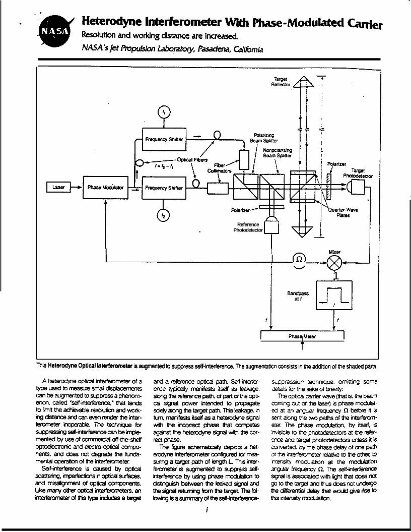
~nyEta~.~atyouthinkbnewMddiltc#dntltwnt)MprioraR Most practical interferometers used for precision sensing are based on a concept of heterodyne interferometer due bo its high-precision readout afforded by the heterodyne signal processing. However, a typical Optical: heterodyne interferometer is limited in its resolution to a few nanometers by a parasitic leakage of optical Signals caged "PO- mixjng" or more generally "W-interference". A number of laboratory techniques have beerr plOflOsed in the past to suppress the self-interference. All of these techniques are very difficult to implement with a predsion required and their implementation often introduces its own noise into the interferometer. For example, cyclic averaging by referem PO- dithering or by ramping of the frequency both degrade the inherent stability of ,jhe interferometer by destabiliing W reference arm or the carrier frequency respectively. This invention, on the otber hand, is very easy to implement, uses commercial off-the-shelf amponents, ar?d affords a very high degree of self-interference suppression without degrading the fundamental operation of the interferometer In the past phase or frequency modulation has been used in a homodyne inteferometer, e.g. H. Telle, US Patent Number 5,539,520 "interferometer using frequency modulation of the canier frequec(c)r. The inverttion described in this reports deals with a phase modulation in a much more practical heterodyne interferometer.
2. Technical Disdosure
Resolution of a hetercdyne interferometer is limited by a parasitic leakage c a l l e d "setf-interference". It occurs, for example, when an optical signal instead of going to4he target goes along the reference path due.to optics imperfections, misalignment, and scattering. It manifests itsetf as a heterodyne signal with a wrong phase that competes with h heterodyne signal with the right phase. If the "good" signal is unattenuated by the optical losses, then the seJf- interference limits the typical interferometer resolution to about 1 nm. If the 'good" signal is attenuated by the opticai losses due to, for example, d*Hfraction over 1 m g target d'rstances, poor target reflectitity, or aperturing of the beam then parasitic signal with the wrong phase can actually dominate over the desired signal and therefore render the interferometer inoperable.
1
NTR Inventor's Repd * .IpL. (Technical Oiscto8ufe Continuation Sheet)
P I
'Frequency Shifter
f=f r f j
Phase Frequency Q LLaserd Modulator Shifter
t
target L reflector
iJ4
)1/4 - quarter wave plate BS - beamsplitter PBS-polarizing beamsplitter
Barn= atf
pol-polarizer f f
photodetector I Phase Meter 1 @ electronic oscillator at frequency Q
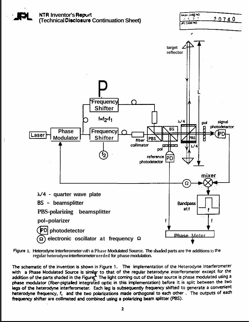
Fgure 1. Heterodyne Interferometer with a Phase Modulated Source. The shaded parts are %e additions to the regular heterodyne interferometer needed for phase modulation.
' JpL (Technical Disclosure Continuation Sheet) NTR Inventor's Report i 0 7 4 i ' ;
Small portions of the two beams are reflected by the non-pola&ing bearnspiittet (8% mixed by the polarizer, and the resulting heterodyne frequency beat detected on the reference photodetector. This b a t sewes as a phase reference against which the signal phase will be measured (reference Dandlicker?). n e light transmitted by the beamsplitter is then redirected by the polarizing beamsplitter. Ideally the interferometer -rates as follows. The p-polarized light is transmitted and serves as an optical phase reference. The s-polarized light is reflected toward the target and is reflected back into the Pes. The polarization of the returning light is rotated by 90 degrees, because it double-passed a quarter-wave plate oriented a t 45 degrees. The beam therefore is transmitted by the PBS to the reference reflector and comes back to the PBS from the other side as s-polarized light, because it was again rotated by 90 degrees by the second quarter-wave plate. At this point the s-polarized beam is recombined with the transmitted p- polarized optical reference beam. The polarized oriented a t 45 degrees mixes the two orthogonally polarized beams and the interference beats are detected by the signal photodetector. If the magnitude and frequency of the phase modulation are chosen appropriately for the target dbtance L, significant beats involving the phase modulation frequency (0) are generated pat the signal photodetector. The desried heterodyne signal can be recovered by demodulating a t wious harmonics of 9. In the implementation shown in Figure I , the demodulation is performed a t I$ which downconverts the Q-f and Q+f components into the beat a t the heterodyne frequency. The key feature of this signal processing scheme is that the magnitude of the produced heterodyne signal is proportional to sin(nnWc),
Sasin(nQwc) where c - speed of light and
LD is the total pathlength difference between the two arms of the interferometer and consists of the pathlength due to target separation (L) and the internal pathlength mismatch of the interferemeter (LINT):
LD=L+L~M The above dependencies allow one to suppress the unwanted signals resulting from self-interference, The self- Itnerference results from the non-ideal operation of the interferometer. First, a portion of the s-polarized beam instead of being entirely reflected by the second P8S toward the target is transmitted directly into the signal photodetector. Similarly, a small portion of the beam travelling to the target may instead be scattered back by the PBS and quarter-wave surfaces. These beams would generate an self-interference beat with a wrong phase in the regular heterodyne interferometer, but in this implementation they are suppressed by the sin(nQLdc). In this case, because the s-polarized beam did not travel to the target, the pathlength difference between the two legs of the interferometer is oniy the internal pathlelength difference, Le. ~ = L I M , which can be made to be very small. Assuming that the interferometer is optimized for operation with a target distance of L, i.e. sin(nnLdc) is an appriciable number, the self- inteference signal is suppressed by a factor of L/Llw. A second source of self-interference results from the s-polarized beam travelling to the target twice. This results from polarization optics and alignment imperfections. This source of self-interference is significant only for low-loss interferometers. In high-loss interferometers it is greatly suppressed by the 10%
associated with an additional roundtrip to the target. The magnitude of the doubie-pass self-interference signal in the Heterodyne lnteferometer with a Phase Modulated Source is proportional to sin(2nQLdc) and therefore can be suppressed by chosing
In effect, phase modulation of the source marks the desired signal returning from the target with an intensity modulation a t the frequency of phase modulation. For other signals the phase modulation of the carrier does '
not result in appriciable intensity moduiation and they are suppressed by demodulation a t the frequencY of phase modula tion.
3
a n = C/(ZLO) C/(ZL)
3
“Reference herein to any specific commercial product, process or service by trade name, trademark manufacturer or otherwise, does not constitute or irrlply its endorsement by the United States Government or the Jet Propulsion Laboratory, California Institute of Technology.”
‘The work described here was canied out at the Jet Propulsion Laboratory, California Institute of Technology under contract with the National Aeronautics and Space Administration.”