elfoenergy ground medium² - cooke industries · centrality of the air renewal terminal and ahu...
TRANSCRIPT

ELFOEnergy Ground Medium²
Nominal heating capacity (operation heating only) (W10/W45) from 35 kW to 420 kW
Nominal cooling capacity (operation cooling only) (W35/W7) from 30 kW to 356 kW
▶ PRE-ASSEMBLED UNIT
▶ APPLICATION VERSATILITY
▶ HIGH SEASONAL EFFICIENCY
Technical Bulletin
Water-cooled chiller for indoor installation
WSH-XEE2 10.2 - 120.2 RANGE
Clivet is taking part in the EUROVENT certification programme up to 1.500 kW. The products concerned appear in the certified products list of the EUROVENT www.eurovent-certification.com site.
BT14G006GB-07
Cooke Industries - Phone:: +64 9 579 2185 Fax: +64 9 579 2181 Email: [email protected] Web: www.cookeindustries.co.nz

Clivet hydronic systemDesigned to provide high energy efficiency and sustainability of the investment, the wide range of Clivet liquid chillers and heat pumps for high efficiency air conditioning of Residential and Commercial spaces and for Industrial applications it is available with air or water source.
SpecializationEvery intended use has specific requirements which determine the overall efficiency. For this, the Clivet hydronic system always offers the best solution in every project.
• Modular range with over 8000 kW of overall capacity
• Capacity control with Screw and modular Scroll technology
• Multifunction versions
• Outdoor or indoor (ductable type) installation
Centrality of the Air Renewal Terminal and AHU complete systemFrom the Air Renewal depends the comfort in the spaces. Since it often represents the main building energetic load, it also determines the running costs of the entire system.
The hydronic terminal units are very diffused for their versatility and reliability. The Clivet range includes many versions that simplify the application in differents type of installation and building.
•
ZEPHIR3
Autonomous primary air energy thermodynamic recovery system
ELFOSpace
High energy efficiency hydronic terminal units
AQX
Air-conditioning unit
• Cased and uncased terminal units, from 1 to 90 kW
• Horizontal and vertical installation
• Energy saving DC fans
• Fitted air conditioning units up to 160.000 m3/h
• EUROVENT certification
• Simplifies the system, reduces the heating and cooling generators
• Purifies the air with the standard electronic filters
• Increases the energy efficiency and it also allows a savings of 40% on the running costs
• From –40°C to +50°C of outdoor air temperature
Cooke Industries - Phone:: +64 9 579 2185 Fax: +64 9 579 2181 Email: [email protected] Web: www.cookeindustries.co.nz

BT14G006GB-07 ELFOEnergy Ground Medium2 3
ELFOEnergy Ground Medium2, three solutions to satisfy different installation requirements
GROUND MEDIUM2 - COOLING ONLY or HEATING ONLYWSH-XEE2:
• Water chiller or non-reversible heat pump
• Partial energy recovery
GROUND MEDIUM2 - HEAT PUMPWSHN-XEE2:
• Reversible-cycle heat pump
Technical bulletin BT14G004GB-10
GROUND MEDIUM2 - MULTIFUNCTIONWSHN-XEE2 MF:
• Reversible-cycle heat pump
• Simultaneous production of hot and chilled water
Technical bulletin BT15A008GB-03
Cooke Industries - Phone:: +64 9 579 2185 Fax: +64 9 579 2181 Email: [email protected] Web: www.cookeindustries.co.nz

4 ELFOEnergy Ground Medium2 BT14G006GB-07
Clivet. Change thing.For 25 years, we have been offering solutions to ensure sustainable comfort and the well-being of people and environment.Clivet’s business strategy has always been clearly defined as the development of high efficiency systems. It has placed its R&D department at the complete disposal of this strategy, investing significant financial and human resources in this area and identifying its mission as “Comfort & Energy Saving”, at a time when issues such as energy saving and high efficiency were not yet as central to public opinion as they are today.
ELFOEnergy Ground MediumELFOEnergy Ground Medium2
Application versatility
ELFOEnergy Ground Medium2 is suited to all types of room heaters, fancoil units, radiant systems and radiators.
Multiple configurations available:
• Groundwater version and closed loop Geothermal version
• Source and user side hydronic units with 1 or 2 ON/OFF pumps or VARYFLOW+ , or alternatively 2-way or 3-way modulating valve
• 3-way valve for domestic hot water preparation (for “heating only” units)
• Partial energy recovery which recovers around 25% of the available condensation heat (for “cooling only” units)
Pre-assembled unit
ELFOEnergy Ground Medium2 can be supplied equipped with components that are often provided separately.
• Reduces design times: all accessories have been selected to assure outstanding seasonal efficiency.
• Reduces installation costs: the accessories are already connected mechanically and electronically wired up, are controlled by a single controller and tested to be ready for immediate use.
• Reduces overall dimensions: the construction and layout of the plumbing components at the back of unit makes it possible, when the heating or chilling power demand is very high, to run several units together, considerably reducing the overall footprint and freeing up space for other equipment while facilitating maintenance.
Cooke Industries - Phone:: +64 9 579 2185 Fax: +64 9 579 2181 Email: [email protected] Web: www.cookeindustries.co.nz

BT14G006GB-07 ELFOEnergy Ground Medium2 5
ELFOEnergy Ground Medium²
Cooling only unit, system solutions:
▶ Production of chilled water (Operation Cooling-only)
▶ Production of chilled water (Operation Cooling-only)
▶ Production of domestic hot water from partial recovery (example post-heat)
Heating only unit, system solutions:
▶ Production of hot water (Operation Heating-only)
▶ Production of hot water (Operation Heating-only)
▶ Production of domestic hot water with 3-way valve
▶ Alternated production for the System or the DHW circuit
Cooke Industries - Phone:: +64 9 579 2185 Fax: +64 9 579 2181 Email: [email protected] Web: www.cookeindustries.co.nz

6 ELFOEnergy Ground Medium2 BT14G006GB-07
High energy efficiency in the annual cycle
ELFOEnergy Ground Medium2 reduces yearly energy consumption thanks to its high partial load efficiency, i.e., by far the most frequent condition throughout the system’s life-cycle, which also increases the value of the property served. The main components are
manufactured on an industrial scale, with maximum manufacturing reliability.
High energy efficiency recovery between 25% and 75% of the system load
The technology of the ELFOEnergy Ground Medium2 sets the energy reference for water source heat pumps. The unit may be equipped with modular scroll technology, ideal for partial loads, an electronic expansion valve for a quick and precise response to the actual service demand, and high performance heat exchangers. The exceptional performance of ELFOEnergy Ground Medium at partial load
makes it much more competitive and efficient than conventional solutions.
The modular scroll is the excellent solution for partial load
ELFOEnergy Ground Medium2 employs highly efficient Scroll compressors, with spirals optimised for this type of use.
The advantages are:
• Compressors manufactured in large numbers on an industrial scale, with strict quality checks and highest reliability thanks to the high scale mass production volumes.
• The two sizes of Scroll compressors allow for several control steps. This way, only the necessary energy is supplied.
• Efficiency increase that can exceed 50% of the operation with part load, thanks to the larger thermal exchange surfaces available.
Electronic expansion valve
The thermostatic electronic expansion valve (TEE) adapts quickly and precisely to the effective load required for use, permitting a stable and accurate adjustment and optimal operation of the compressor.
There is also an additional increase in efficiency in comparison to traditional thermostatic mechanical valves (TEM) and a longer compressor life.
Maximum exchange efficiency
The high energy efficiency of ELFOEnergy Ground Medium2 is achieved by carefully dimensioning and rating all components.
To ensure optimal exchange in every climatic condition, the unit has been fitted with generously sized exchangers that have an anticondensation external thermal insulation and an anti-freeze heater to prevent ice from forming.
Cooke Industries - Phone:: +64 9 579 2185 Fax: +64 9 579 2181 Email: [email protected] Web: www.cookeindustries.co.nz

BT14G006GB-07 ELFOEnergy Ground Medium2 7
A complete offering
Water flow-rate continuous modulation (optional)
ELFOEnergy Ground Medium2 enables adoption of both hot and cold side hydronic units.
The energy used for the vector pumping is fundamental on the seasonal efficiency.
The VARYFLOW + modulating pumping unit made up of two pumps in parallel controlled by inverter, allows a precise water flow-rate modulation reducing notably the consumptions and at the same time it guarantees its functionality also in case of temporary unavailability of one of the two pumps, guaranteeing about the 80% of the nominal flow-rate.
The water flow is modulated by keeping the delivery/return water temperature differential constant.
When the system water temperature is critical, the VARYFLOW+ controls the condensation/evaporation temperature by extending the operating range of ELFOEnergy Ground Medium2.
In case of particular installation needs, the hydronic assemblies are also available:
• ON/OFF pump: the traditional solution with high available pressure.
• ON/OFF pump + ON/OFF pump in stand-by: the solution that favours reliability. The built-in control balances the operating hours of the two pump and in case of any failure it signals the damage and automatically activates the stand-by pump.
• 2-way or 3-way modulating valves with electronic control, extend the unit’s operating range by modulating the source water flow in relation to temperature.
Advanced control
The control system combines in a single solution the operating efficiency and the user-friendliness.
Continuously monitoring all of the unit operating parameters, it ensures the maintenance of an optimal energy efficiency.
The control includes many safety functions and a complete alarm management.
It also includes advanced functions, such as daily and weekly programming and automatic maximum power consumption limitation (demand limit).
It allows the management of several units in cascade up to 1 master and 6 slave (Ecoshare)
The interface terminal is equipped with a backlit graphic display and a multifunction access keyboard. The multilevel menu is protected by different passwords according
to the type of user.
Remote control
The remote control allows accessing to the same functions that are accessible by the built-in unit user interface, and can be installed at a maximum distance of 350 meters.
System remote management
Thanks to the different available communication devices, the unit is able to exchange information with the main supervision systems by serial connections.
Cooke Industries - Phone:: +64 9 579 2185 Fax: +64 9 579 2181 Email: [email protected] Web: www.cookeindustries.co.nz

8 ELFOEnergy Ground Medium2 BT14G006GB-07
Heating only unit - configuration
(1) OperationOCO - Cooling onlyOHO - Heating only (standard)OHI - Operation with water circuit change-over
(2) VersionGW - Groundwater version (standard)GEO - Version for Geothermal application
(3) VoltageSupply voltage 400/3/50
(4) Cold side hydronic unitRefer to the diagrams of the hydronic assembly reported
(5) Hot side hydronic unitRefer to the diagrams of the hydronic assembly reported
(6) Larger unitsVS - Standard enclosureMOBMAG - Larger units
(7) Power capacitors(-) not required (standard)PFCP - Power factor correction capacitors (cosfi>0.9)
(8) Soft starter(-) not required (standard)SFSTR - Disposal for inrush current reduction (only for sizes from 10.2 to 80.2)
(9) Phase monitorPM - Phase monitor (standard)MF2 - Multi-function phase monitor
(10) Comunication modules(-) not required (standard)CMSC8 - Serial communication module to BACnet supervisorCMSC9 - Serial communication module to Modbus supervisorCMSC10 - Serial communication module to LonWorks supervisor
(11) Cutoff valve(-) not required (standard)SDV - Cutoff valve on compressor supply and return (only for sizes from 10.2 to 80.2)
Functionalities Diagram hydronic assemblies - Heating only unit
2-PIPE SYSTEM
HOT SIDE
Standardunit(Std)
Unitwith VARYFLOW +
(VARYH)
Unitwith one ON/OFF pump
(HYGH1)
Unitwith two ON/OFF pumps
(HYGH2)
2-PIPE SYSTEM
COLDSIDE
Standardunit(Std)
Unitwith VARYFLOW +
(VARYC)
Unitwith one ON/OFF
pump(HYGC1)
Unitwith two ON/OFF
pumps(HYGC2)
Unitwith 3-way modu-
lating valve(VS3MC)
Unitwith 2-way modu-
lating valve(VS2MC)
Accessori forniti separatamente
• SPCX - Set point compensation with outdoor air temperature probe
• RCTX - Remote control
• BACX - BACnet serial communication module• CMMBX - Serial communication module to supervisor (MODBUS)• CMSLWX - LonWorks serial communication module
• VS2MCX - Cooling side 2-way modulating valve
• VS3MCX - Cooling side 3-way modulating valve
• VACSHX - Heating side domestic hot water
switching valve
• AVIBX - Anti-vibration mount supports
• IFWX - Steel mesh strainer on the water side
Cooke Industries - Phone:: +64 9 579 2185 Fax: +64 9 579 2181 Email: [email protected] Web: www.cookeindustries.co.nz

BT14G006GB-07 ELFOEnergy Ground Medium2 9
Cooling only unit - configuration
(1) OperationOCO - Cooling only (standard)OHO - Heating onlyOHI - Operation with water circuit change-over
(2) VersionGW - Groundwater version (standard)GEO - Version for Geothermal application
(3) VoltageSupply voltage 400/3/50
(4) Cold side hydronic unitRefer to the diagrams of the hydronic assembly reported
(5) Hot side hydronic unitRefer to the diagrams of the hydronic assembly reported
(6) Larger unitsVS - Standard enclosureMOBMAG - Larger units
(7) Partial recovery device(-) not required (standard)D - Partial energy recovery (only for sizes from 10.2 to 90.2)
(8) Power capacotors(-) not required (standard)PFCP - Power factor correction capacitors (cosfi>0.9)
(9) Soft starter(-) not required (standard)SFSTR - Disposal for inrush current reduction (only for sizes from 10.2 to 80.2)
(10) Phase monitorPM - Phase monitor (standard)MF2 - Multi-function phase monitor
(11) Communication modules(-) not required (standard)CMSC8 - Serial communication module to BACnet supervisorCMSC9 - Serial communication module to Modbus supervisorCMSC10 - Serial communication module to LonWorks supervisor
(12) Cutoff valve(-) not required (standard)SDV - Cutoff valve on compressor supply and return (only for sizes from 10.2 to 80.2)
Functions Diagram hydronic assemblies - Cooling only unit
2-PIPE SYSTEM
HOT SIDE
StandardUnit(Std)
Unit withVARYFLOW+
(VARYH)
Unit withone ON/OFF pump
(HYGH1)
Unit withtwo ON/OFF pumps
(HYGH2)
Unit with3-way
modulating valve(VS3MH)
Unit with2-way
modulating valve(VS2MH)
2-PIPE SYSTEM
COLDSIDE
StandardUnit(Std)
Unit withVARYFLOW+
(VARYC)
Unit withone ON/OFF pump
(HYGC1)
Unit withtwo ON/OFF pumps
(HYGC2)
2-PIPE SYSTEM
COLDSIDE
+PARTIAL
RECOVERY
Unit withpartial recovery
(D)
Unit withpartial recovery and
VARYFLOW+(D+VARYC)
Unit withpartial recovery andone ON/OFF pump
(D+HYGC1)
Unit withpartial recovery andtwo ON/OFF pumps
(D+HYGC2)
Accessori forniti separatamente
• SPCX - Set point compensation with outdoor air temperature probe
• RCTX - Remote control
• BACX - BACnet serial communication module• CMMBX - Serial communication module to supervisor
(MODBUS)• CMSLWX - LonWorks serial communication module
• VS2MHX - Hot side 2-way modulating valve
• VS3MHX - Hot side 3-way modulating valve
• AVIBX - Anti-vibration mount supports
• IFWX - Steel mesh strainer on the water side
Cooke Industries - Phone:: +64 9 579 2185 Fax: +64 9 579 2181 Email: [email protected] Web: www.cookeindustries.co.nz

10 ELFOEnergy Ground Medium2 BT14G006GB-07
General technical dataGroundwater version
Size 10.2 12.2 14.2 16.2 19.2 22.2 27.2 30.2 35.2 40.2 43.2 45.2 50.2 55.2 60.2 70.2 80.2 90.2 100.2 120.2
Radiant panels
Heating only operationHeating capacity (EN14511:2013) 1 kW 37,1 42,8 51,7 60,1 71,3 83,8 101 114 132 149 164 177 193 209 238 268 302 340 371 437
Total power input (EN14511:2013) 2 kW 6,78 8,04 9,68 11,4 13,2 16,2 18,2 21,4 24,4 27,8 31,3 32,8 35,6 39,5 44,6 50,7 57,3 64,9 70,2 84,8
COP (EN 14511:2013) 3 5,47 5,33 5,34 5,29 5,42 5,16 5,54 5,35 5,39 5,36 5,24 5,41 5,41 5,30 5,35 5,30 5,28 5,24 5,28 5,16
Cooling only operation
Cooling capacity (EN14511:2013) 6 kW 41,9 57,8 57,5 66,8 79,6 91,3 112 126 147 166 183 198 216 234 266 297 335 377 406 473
Total power input (EN14511:2013) 2 kW 6,67 8,28 10,2 11,9 13,7 16,8 18,4 21,2 25,3 28,4 32,7 34,2 37,4 41,4 47,1 54,0 62,4 67,4 74,6 88,8
EER (EN 14511:2013) 7 6,27 5,76 5,67 5,63 5,81 5,45 6,10 5,95 5,82 5,84 5,58 5,80 5,78 5,64 5,63 5,51 5,37 5,59 5,45 5,33
Terminal unitsHeating only operationHeating power (EN14511:2013) 4 kW 35,8 41,4 49,6 57,8 68,6 81,0 96,7 109 126 143 157 169 184 200 227 257 290 328 355 420
Total power input (EN14511:2013) 2 kW 8,27 9,79 11,6 13,5 15,7 19,2 21,8 25,3 28,9 32,8 36,7 38,7 41,9 46,5 52,4 59,2 66,7 76,6 83,4 101
COP (EN 14511:2013) 3 4,33 4,23 4,26 4,29 4,37 4,23 4,43 4,32 4,35 4,35 4,27 4,37 4,39 4,30 4,33 4,34 4,34 4,28 4,25 4,16
Cooling only operationCooling capacity (EN14511:2013) 8 kW 30,8 35,4 42,7 49,6 59,1 68,4 83,8 94,4 109 123 135 147 159 172 197 221 249 280 305 356
Total power input (EN14511:2013) 2 kW 6,45 7,63 9,22 10,8 12,5 15,6 17,5 20,4 23,5 26,6 29,8 31,5 34,1 37,7 42,7 48,2 54,7 61,5 68,4 82,4
EER (EN 14511:2013) 7 4,77 4,64 4,63 4,61 4,72 4,39 4,80 4,63 4,62 4,63 4,53 4,65 4,68 4,58 4,60 4,59 4,55 4,56 4,46 4,32
ESEER (EN 14511:2013) 9 6,31 6,20 5,65 5,52 5,71 5,51 6,19 6,05 6,03 6,02 5,78 6,00 5,97 5,79 5,62 5,78 5,48 5,52 5,48 5,31
RadiatorsHeating only operationUnit with one ON/OFF pump (HYGSW1) 5 33,2 38,8 46,3 53,9 63,2 74,6 88,6 101 116 132 146 156 170 186 210 237 267 303 330 395
Total power input (EN14511:2013) 2 10,3 12,2 14,4 16,6 19,3 23,0 26,7 30,4 35,1 39,6 44,6 47,0 51,1 56,4 63,8 71,2 79,8 93,1 102 125
COP (EN 14511:2013) 3 3,22 3,17 3,21 3,25 3,27 3,24 3,32 3,32 3,30 3,32 3,27 3,31 3,33 3,29 3,29 3,33 3,35 3,26 3,24 3,17
CompressorType of compressors Scroll Scroll Scroll Scroll Scroll Scroll Scroll Scroll Scroll Scroll Scroll Scroll Scroll Scroll Scroll Scroll Scroll Scroll Scroll Scroll
No. of compressors No 2 2 2 2 2 2 2 2 2 2 2 2 2 2 2 2 2 2 2 2
Std Capacity control steps No 3 3 2 3 3 3 3 2 3 3 3 3 3 3 2 3 2 3 3 2
Oil charge l 3,00 3,00 3,00 6,00 6,00 6,00 7,00 7,00 8,00 10,1 11,5 11,0 11,0 13,1 12,6 12,6 12,6 12,6 12,6 12,6
Refrigerant charge kg 3,8 4,1 4,4 7,4 7,7 8,5 9,4 11 13 14 15 15 18 21 22 24 25 28 29 31
Refrigeration circuits No 1 1 1 1 1 1 1 1 1 1 1 1 1 1 1 1 1 1 1 1
Internal exchangerType of internal exchanger 10 PHE PHE PHE PHE PHE PHE PHE PHE PHE PHE PHE PHE PHE PHE PHE PHE PHE PHE PHE PHE
No. of internal exchangers No 1 1 1 1 1 1 1 1 1 1 1 1 1 1 1 1 1 1 1 1
Water flow-rate (Cool side) 8 l/s 1,50 1,70 2,10 2,40 2,80 3,30 4,00 4,50 5,20 5,90 6,50 7,00 7,70 8,30 9,40 10,6 12,0 13,5 14,7 17,1
External exchangerType of external exchanger 10 PHE PHE PHE PHE PHE PHE PHE PHE PHE PHE PHE PHE PHE PHE PHE PHE PHE PHE PHE PHE
No. of external exchangers No 1 1 1 1 1 1 1 1 1 1 1 1 1 1 1 1 1 1 1 1
Water flow rate (Heat Side) 8 l/s 1,80 2,00 2,50 2,90 3,40 4,00 4,80 5,50 6,30 7,10 7,80 8,50 9,20 10,0 11,4 12,8 14,4 16,3 17,8 20,9
ConnectionsWater fittings (Standard units) 1’ 1/4 1’ 1/4 1’ 1/4 1’ 1/4 1’ 1/4 1’ 1/4 2’1/2 2’1/2 2’1/2 2’1/2 2’1/2 2’1/2 2’1/2 2’1/2 2’1/2 2’1/2 2’1/2 2’1/2 3’ 3’
Water fittings (Larger units) 2’ 2’ 2’ 2’ 2’ 2’ 3’ 3’ 3’ 3’ 3’ 3’ 3’ 3’ 3’ 3’ 3’ 3’ 4’ 4’
Water circuitMaximum water side pressure 11 MPa 1,0 1,0 1,0 1,0 1,0 1,0 1,0 1,0 1,0 1,0 1,0 1,0 1,0 1,0 1,0 1,0 1,0 1,0 1,0 1,0
Min. installation water contents 12 l 245 233 369 387 373 341 596 810 802 780 998 743 970 1271 1690 1633 2157 1442 1993 3113
Power supplyStandard power supply V 400/3/50 400/3/50 400/3/50 400/3/50 400/3/50 400/3/50 400/3/50 400/3/50 400/3/50 400/3/50 400/3/50 400/3/50 400/3/50 400/3/50 400/3/50 400/3/50 400/3/50 400/3/50 400/3/50 400/3/50
Note: The unit can operate in cooling-only or in heating-only mode.
1. Data referred to the following conditions: Cold side exchanger water 30/35°C. Hot side exchanger water 10/7°C. Performance data calculated with reference to EN14511:2013
2. The total power draw is calculated by adding the compressor’s power draw + the draw required to overcome the internal cold and hot side pressure drops + the control circuit power draw
3. COP (EN 14511:2013) heating performance coefficient. Ratio between delivered heating capacity and power input in compliance with EN 14511:2013
4. Data referred to the following conditions: Cold side exchanger water 40/45°C. Hot side exchanger water 10/7°C. Performance data calculated with reference to EN14511:2013
5. Data referred to the following conditions: Cold side exchanger water 50/55°C. Hot side exchanger water 10/7°C. Performance data calculated with reference to EN14511:2013
6. Data referred to the following conditions: Cold side exchanger water 23/18°C. Hot side exchanger water 30/35 °C. Performance data calculated with reference to EN14511:2013
7. EER (EN 14511:2013) cooling performance coefficient. Ratio between delivered cooling capacity and power input in compliance with EN 14511:2013
8. Data referred to the following conditions: Cold side exchanger water 12/7°C. Hot side exchanger water 30/35 °C. Performance data calculated with reference to EN14511:2013
9. ESEER calculated per EUROVENT, for installations with terminal units with water produced at 7 °C and constant hot side flow10. PHE = plate exchanger11. Conditions for the circuit on the utility side and the circuit on the source side. In configurations with hydronic units, the maximum
pressure on the water side is 600 kPa.12. The minimum system water content calculated value does not consider the internal exchanger water content. With applications or
low medium requested loads, the minimum installation water volume is obtained doubling the indicated value
Cooke Industries - Phone:: +64 9 579 2185 Fax: +64 9 579 2181 Email: [email protected] Web: www.cookeindustries.co.nz

BT14G006GB-07 ELFOEnergy Ground Medium2 11
General technical dataGeothermic version
Size 10.2 12.2 14.2 16.2 19.2 22.2 27.2 30.2 35.2 40.2 43.2 45.2 50.2 55.2 60.2 70.2 80.2 90.2 100.2 120.2
Radiant panels
Heating only operation
Heating capacity (EN14511:2013) 1 kW 27,7 32,4 38,3 45,7 54,1 63,9 75,2 85,0 95,7 111 121 130 140 155 174 197 219 247 266 313
Total power input (EN14511:2013) 2 kW 6,61 7,55 9,01 10,6 12,4 15,2 16,8 19,4 22,4 25,6 28,4 30,0 32,5 36,0 40,6 45,4 50,9 59,2 65,0 79,7
COP (EN 14511:2013) 3 4,19 4,29 4,26 4,32 4,35 4,21 4,47 4,38 4,28 4,32 4,27 4,33 4,31 4,32 4,28 4,33 4,30 4,17 4,09 3,93
Terminal units
Heating only operation
Heating capacity (EN14511:2013) 4 kW 27,4 32,1 37,7 45,0 52,8 62,5 73,4 83,2 93,7 108 119 127 138 153 170 193 215 244 263 309
Total power input (EN14511:2013) 2 kW 8,18 9,51 11,2 13,1 15,3 18,3 20,6 23,5 27,1 31,0 34,5 36,5 39,6 43,8 49,6 55,2 61,6 72,4 79,1 97,3
COP (EN 14511:2013) 3 3,35 3,37 3,36 3,44 3,45 3,42 3,56 3,55 3,46 3,49 3,45 3,49 3,48 3,48 3,44 3,49 3,50 3,37 3,32 3,18
Compressor
Type of compressors Scroll Scroll Scroll Scroll Scroll Scroll Scroll Scroll Scroll Scroll Scroll Scroll Scroll Scroll Scroll Scroll Scroll Scroll Scroll Scroll
No. of compressors Nr 2 2 2 2 2 2 2 2 2 2 2 2 2 2 2 2 2 2 2 2
Std Capacity control steps Nr 3 3 2 3 3 3 3 2 3 3 3 3 3 3 2 3 2 3 3 2
Oil charge (C1) l 3,00 3,00 3,00 6,00 6,00 6,00 7,00 7,00 8,00 10,1 11,5 11,0 11,0 13,1 12,6 12,6 12,6 12,6 12,6 12,6
Refrigerant charge kg 3,8 4,1 4,4 7,4 7,7 8,5 9,4 11 13 14 15 15 18 21 22 24 25 28 29 31
Refrigeration circuits Nr 1 1 1 1 1 1 1 1 1 1 1 1 1 1 1 1 1 1 1 1
Internal exchanger
Type of internal exchanger 5 PHE PHE PHE PHE PHE PHE PHE PHE PHE PHE PHE PHE PHE PHE PHE PHE PHE PHE PHE PHE
No. of internal exchangers Nr 1 1 1 1 1 1 1 1 1 1 1 1 1 1 1 1 1 1 1 1
Water flow-rate (Heat side) l/s 1,31 1,53 1,79 2,14 2,51 2,97 3,49 3,96 4,46 5,15 5,66 6,06 6,56 7,26 8,11 9,17 10,24 11,61 12,51 14,71
External exchanger
Type of external exchanger 5 PHE PHE PHE PHE PHE PHE PHE PHE PHE PHE PHE PHE PHE PHE PHE PHE PHE PHE PHE PHE
No. of external exchangers Nr 1 1 1 1 1 1 1 1 1 1 1 1 1 1 1 1 1 1 1 1
Water flow-rate (Cool side) l/s 1,66 1,95 2,29 2,76 3,24 3,83 4,52 5,13 5,72 6,63 7,25 7,78 8,42 9,33 10,37 11,80 13,19 14,73 15,80 18,25
Connections
Water fittings (standard units) 1’ 1/4 1’ 1/4 1’ 1/4 1’ 1/4 1’ 1/4 1’ 1/4 2’1/2 2’1/2 2’1/2 2’1/2 2’1/2 2’1/2 2’1/2 2’1/2 2’1/2 2’1/2 2’1/2 2’1/2 3’ 3’
Water fittings (Larger units) 2’ 2’ 2’ 2’ 2’ 2’ 3’ 3’ 3’ 3’ 3’ 3’ 3’ 3’ 3’ 3’ 3’ 3’ 4’ 4’
Water circuit
Maximum water side pressure 6 MPa 1,0 1,0 1,0 1,0 1,0 1,0 1,0 1,0 1,0 1,0 1,0 1,0 1,0 1,0 1,0 1,0 1,0 1,0 1,0 1,0
Power supply
Standard power supply V 400/3/50 400/3/50 400/3/50 400/3/50 400/3/50 400/3/50 400/3/50 400/3/50 400/3/50 400/3/50 400/3/50 400/3/50 400/3/50 400/3/50 400/3/50 400/3/50 400/3/50 400/3/50 400/3/50 400/3/50
Dati riferiti alle seguenti condizioni: acqua allo scambiatore interno 30/35°C. Acqua allo scambiatore esterno 0/-3°C. Dati riferiti al funzionamento con miscela di acqua e glicole propilenico al 30% lato sorgente. Dati prestazionali calcolati in riferimento alla norm
Not: The unit only works in hot mode.1. Data referred to the following conditions: Hot side exchanger water 30/35 °C. Cold side exchanger water 0/-3 °C. Operation with 30% cold side mixture of water and propylene glycol. Performance data calculated with reference to EN14511:20132. The total power draw is calculated by adding the compressor’s power draw + the draw required to overcome the internal cold and hot side pressure drops + the control circuit power draw3. COP (EN 14511:2013) heating performance coefficient. Ratio between delivered heating capacity and power input in compliance with EN 14511:20134. Data referred to the following conditions: Hot side exchanger water 40/45°C. Cold side exchanger water 0/-3 °C. Operation with 30% cold side mixture of water and propylene glycol. Performance data calculated with reference to EN14511:20135. PHE = plate exchanger6. Conditions for the circuit on the utility side and the circuit on the source side. In configurations with hydronic units, the maximum
pressure on the water side is 600 kPa.
Cooke Industries - Phone:: +64 9 579 2185 Fax: +64 9 579 2181 Email: [email protected] Web: www.cookeindustries.co.nz

12 ELFOEnergy Ground Medium2 BT14G006GB-07
Electrical data
Size 10.2 12.2 14.2 16.2 19.2 22.2 27.2 30.2 35.2 40.2 43.2 45.2 50.2 55.2 60.2 70.2 80.2 90.2 100.2 120.2
F.L.A. - Full load current at max admissible conditions
F.L.A. - Total A 19,9 23,8 28,9 31,5 36,4 44,9 51,8 60,3 66,8 74,9 81,4 89,6 96,1 104 119 133 148 173 188 228
F.L.I. - Full load power input at max admissible conditions
F.L.I. - Total kW 11,9 14,0 16,8 19,5 22,4 26,3 30,2 34,1 39,6 44,6 50,2 53,1 58,7 63,7 72,2 81,0 90,0 106 116 140
M.I.C. Maximum inrush current
M.I.C. - Value A 73,7 111 116 126 133 189 196 204 256 302 309 340 347 355 370 468 482 443 458 499
M.I.C. with soft start accessory A 44,9 65,2 70,3 76,2 80,0 111 118 126 154 180 187 201 208 216 230 284 299 - - -
Power supply: 400/3/50 Hz. Voltage variation: max. +/-10%Voltage unbalance between phases: max 2 %For non standard voltage please contact Clivet technical officeUnits are in compliance with the europeans law CEI EN 60204 and CEI EN 60335
Sound levels
Size
Sound power level (dB) Sound power level
Sound pressure levelOctave band (Hz)
63 125 250 500 1000 2000 4000 8000 dB(A) dB(A)
10.2 78 70 62 52 52 43 41 40 60 44
12.2 78 69 62 56 52 44 43 38 60 44
14.2 78 67 61 57 54 46 44 39 60 45
16.2 78 71 66 63 53 49 46 41 64 49
19.2 78 73 67 63 55 51 47 42 65 49
22.2 78 73 65 62 55 52 47 42 64 49
27.2 78 73 66 62 56 54 48 44 64 49
30.2 78 74 63 60 56 54 48 44 64 49
35.2 81 83 80 67 61 61 52 45 74 58
40.2 81 79 80 67 65 63 55 50 74 58
43.2 81 83 83 69 66 65 56 49 77 60
45.2 81 78 80 69 66 62 55 48 74 58
50.2 81 83 83 70 67 64 56 47 77 60
55.2 81 80 83 70 68 65 57 50 77 60
60.2 81 80 83 71 69 65 57 50 77 61
70.2 82 80 85 73 72 68 60 51 79 63
80.2 82 80 85 73 74 70 61 52 80 63
90.2 83 81 86 74 75 71 62 53 81 64
100.2 83 81 86 74 75 71 62 53 81 64
120.2 84 82 87 75 76 72 63 54 82 65
Sound levels refer to units with full load under nominal test conditions.The sound pressure level refers to a distance of 1 meter from the outer surface of the unit operating in open field.Noise levels are determined using the tensiometric method (UNI EN ISO 9614-2)Data referred to the following conditions:Entering / leaving exchanger water temperature user side 12/7°CEntering / leaving exchanger water temperature source side 30/35°C
Cooke Industries - Phone:: +64 9 579 2185 Fax: +64 9 579 2181 Email: [email protected] Web: www.cookeindustries.co.nz

BT14G006GB-07 ELFOEnergy Ground Medium2 13
Cooling only unitOperating Range (Cooling)
Size 10.2 - 12.2 - 14.2 Size 16.2
Size 19.2-22.2-27.2-30.2-35.2-40.2-45.2 Sizes 43.2-50.2-55.2-60.2-70.2-80.2-90.2-100.2-120.2
Twu [°C] = Cold side water outlet temperatureTws [°C] = Hot side water outlet temperatureThe limits refer to DT=5 °C on both the hot and cold sides1. Normal operating range2. Range of operation with modulating valve or hot side regulating inverter pump (optional configurations)
Cooke Industries - Phone:: +64 9 579 2185 Fax: +64 9 579 2181 Email: [email protected] Web: www.cookeindustries.co.nz
14 ELFOEnergy Ground Medium2 BT14G006GB-07
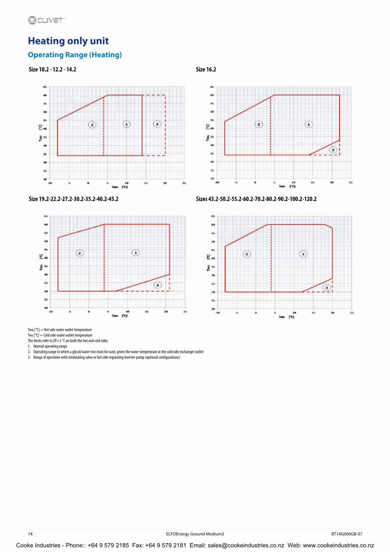
Heating only unitOperating Range (Heating)
Size 10.2 - 12.2 - 14.2 Size 16.2
Size 19.2-22.2-27.2-30.2-35.2-40.2-45.2 Sizes 43.2-50.2-55.2-60.2-70.2-80.2-90.2-100.2-120.2
Twu [°C] = Hot side water outlet temperatureTws [°C] = Cold side water outlet temperatureThe limits refer to DT=5 °C on both the hot and cold sides1. Normal operating range2. Operating range in which a glycol/water mix must be used, given the water temperature at the cold side exchanger outlet3. Range of operation with modulating valve or hot side regulating inverter pump (optional configurations)
Cooke Industries - Phone:: +64 9 579 2185 Fax: +64 9 579 2181 Email: [email protected] Web: www.cookeindustries.co.nz

BT14G006GB-07 ELFOEnergy Ground Medium2 15
Admissible water flow ratesMin. (Qmin) and max. (Qmax) water flow-rates admissibles for the correct unit operation.
10.2 12.2 14.2 16.2 19.2 22.2 27.2 30.2 35.2 40.2 43.2 45.2 50.2 55.2 60.2 70.2 80.2 90.2 100.2 120.2
Heating side
Qmin [l/s] 0,8 0,8 0,8 1,0 1,1 1,1 1,8 1,8 1,8 2,4 2,4 2,4 2,9 2,9 2,9 3,8 3,8 5,3 9,5 10,5
Qmax [l/s] 4,2 4,2 4,3 4,8 4,9 5,1 8,8 8,8 9,3 11,4 11,9 12,2 14,4 15,0 15,4 18,3 19,0 23,5 28,0 29,0
Cooling side
Qmin [l/s] 0,8 0,8 0,8 1,0 1,1 1,1 1,9 1,9 2,6 2,6 2,6 3,5 3,5 3,5 4,5 4,5 5,0 5,0 8,5 8,5
Qmax [l/s] 3,5 3,5 4,3 4,4 4,9 5,1 8,5 8,5 11,5 11,5 11,5 14,5 14,5 15,0 18,0 18,5 21,5 22,0 27,0 27,0
Correction factors for glycol use% ethylene glycol by weight 5% 10% 15% 20% 25% 30% 35% 40%
Freezing temperature °C -2,0 -3,9 -6,5 -8,9 -11,8 -15,6 -19,0 -23,4
Safety temperature °C 3,0 1,0 -1,0 -4,0 -6,0 -10,0 -14,0 -19,0
Cold side exchanger chiller power factor – 0,995 0,990 0,985 0,981 0,977 0,974 0,971 0,968
Cold side exchanger compressor power draw factor – 0,997 0,993 0,990 0,988 0,986 0,984 0,982 1,124
Cold side exchanger glycol solution flow factor – 1,003 1,010 1,020 1,033 1,050 1,072 1,095 1,124
Cold side exchanger pressure drop factor – 1,029 1,060 1,090 1,118 1,149 1,182 1,211 1,243
Fouling Correction Factors
Evaporator Condenser
m² °C/W F1 FK1 F1 FK1
0,44 x 10^(-4) 1,00 1,00 1,00 1,00
0,88 x 10^(-4) 0,97 0,99 0,97 1,08
1,76 x 10^(-4) 0,94 0,98 0,92 1,05
F1 = Cooling capacity correction factorsFK1 = Compressor power input correction factor
Overload and control device calibrations
Intervention Reset Value
High pressure switch (gas side) [kPa] 4050 3300 –
Low pressure alarm (gas side) [kPa] 450 600 –
Low pressure switch (GEO) (gas side) [bar] 200 350 –
Antifreeze protection [°C] 4 6,0 –
high pressure safety valve (gas side) [kPa] – – 4500
Low pressure safety valve (gas side) [kPa] – – 3000
Max no. of compressor starts per hour (gas side) [No] – – 10
Differential pressure switch (water side) [kPa] 3 5 -
Max. pressure without hydronic assembly (water side) [kPa] - - 1000
Max. pressure with hydronic assembly (water side) [kPa] - - 600
Safety valve calibration (water side) (1) [kPa] - - 600
(1) Available only with hydronic assembly option
Cooke Industries - Phone:: +64 9 579 2185 Fax: +64 9 579 2181 Email: [email protected] Web: www.cookeindustries.co.nz

16 ELFOEnergy Ground Medium2 BT14G006GB-07
Standard unit technical specifications
CompressorHermetic Scroll compressors with orbiting spiral, equipped with motor protective device for overtemperatures, overcurrents and excessive temperatures of the supply gas. They are mounted on rubber antivibration mounts and comes with a full oil charge. The compressors come with a thermal and acoustic insulation jacket. An automatic oil heater prevents the oil from being diluted by the refrigerant when the compressor stops. The compressors are connected in TANDEM on a single refrigerating circuit and have a biphasic oil equalisation.
StructureSupporting structure made with zinc-magnesium sheet metal that ensures excellent mechanical features and high long-term resistance against corrosion.
PanellingExternal panelling in zinc-magnesium sheet, prepainted RAL 9003, clad internally with heatproof and soundproof material. The panels are easy to remove when access to the internal components is required.
Coolside exchangerDirect expansion heat exchanger with braze welded stainless steel INOX AISI 316 plates and complete with external thermal/anti-condensation insulation.
The exchanger has Victaulic hydraulic connections.
Heating side exchangerDirect expansion heat exchanger with braze welded stainless steel INOX AISI 316 plates and complete with external thermal/anti-condensation insulation.
The exchanger has Victaulic hydraulic connections.
Refrigeration circuitRefrigeration circuit with:
• anti-acid dehydrator filter
• liquid flow and moisture indicator
• electronic expansion valve
• safety high pressure switch
• low pressure transducer
• high pressure transducer
• high pressure safety valve
• low pressure safety valve
• refrigerant charge
Water circuit
Cooling side• victaulic connection joints
• differential pressure switch, water side
• drain cock (with hydronic units)
• minimum circuit charge pressure switch (with hydronic units)
Heating side• victaulic connection joints
• differential pressure switch, water side
• drain cock (with hydronic units)
• minimum circuit charge pressure switch (with hydronic units)
Cooke Industries - Phone:: +64 9 579 2185 Fax: +64 9 579 2181 Email: [email protected] Web: www.cookeindustries.co.nz

BT14G006GB-07 ELFOEnergy Ground Medium2 17
Electrical panelThe capacity section includes:
• main door lock isolator switch
• isolating transformer for auxiliary circuit power supply
• compressor overload protection (in the range between 10.2 and 80.2)
• compressor protection fuse (in the range between 90.2 and 120.2)
• compressor control contactor
• double winding on compressor for reduction of inrush current (in the range between 90.2 and 120.2)
The control section includes:
• interface terminal with graphic display
• display of the set values, the error codes and the parameter index
• keys for ON/OFF control, cool and heat operating modes, alarm reset
• proportional-integral water temperature control
• daily, weekly programmer of temperature set-point and unit on/off
• set-point compensation with 0-10 V signal
• unit switching on management by local or remote (serial)
• antifreeze protection water side
• compressor overload protection and timer
• prealarm function for water antifreeze and high refrigerant gas pressure
• self-diagnosis system with immediate display of the fault code
• automatic rotation control for compressor starts
• compressor operating hour display
• Input for remote ON/OFF control
• potential-free contact for summer / winter change
• dry contacts to control the cumulative alarm signal remotely
• inlet for demand limit (power input limitation according to a 0÷10V external signal)
• double setpoint enabling
• potential-free contacts for compressor status
• phase monitor
• ECOSHARE function for the automatic management of a group of units
• 0÷10V signal output and potential-free contact for auxiliary heater
• enabling of DHW preparation in relation to remote consent
• numeration of electrical panel cables
• designed for natural cooling management (provided by the customer)
• configuration for single on/off pump or service and source side modulating valve
Accessories
• IFWX - Steel mesh strainer on the water side
• SPCX - Set-point compensation with outdoor air temperature probe
• RCTX - Remote control
• AVIBX - Anti-vibration mount supports
• CMMBX - Serial communication module to supervisor (MODBUS)
• CMSLWX - LonWorks serial communication module
• BACX - BACnet serial communication module
• AVIBX - Anti-vibration mount supports
• VS2MCX - Cold side 2-way modulating valve
• VS3MCX - Cold side 3-way modulating valve
• VS2MHX - Hot side 2-way modulating valve
• VS3MHX - Hot side 3-way modulating valve
• VACSHX - Heating side DHW switching valve
Cooke Industries - Phone:: +64 9 579 2185 Fax: +64 9 579 2181 Email: [email protected] Web: www.cookeindustries.co.nz

18 ELFOEnergy Ground Medium2 BT14G006GB-07
Electronic control
Description of step start-up controlThe electronic control allows to manage the unit depending on the requested load.
The compressor power steps are activated to maximise efficiency from the lowest to the highest setting.
Main controlsLeaving water temperature control with PID algorithm: it keeps the leaving mean temperature to a set value.
• Auto-adaptive switching on differential: guarantees the compressors minimum operating time in systems with low water content.
• Condensation control based on pressure
• Pre-alarms at automatic reset: in case of alarm it is allowed a certain number of restarts before the definitive lock.
• Compressor operating hour calculation
• Compressor start calculation
• Control and continuous management of the compressor operating conditions to guarantee the unit operating also in extreme conditions
• Water temperature check (when used) to avoid the pipe freezing
• Alarm log
• Autostart after voltage drop
• Local or remote control
Unit status displayBy the user interface is possible to display:
• Unit operating mode and status
• Leaving/entering water temperature
• Chiller circuit temperatures and pressures
• Signalling of alarms and anomalies in progress.
Probe, transducer and parameter displayA user interface dedicated section allows the maintenance or technical assistance personnel to control the unit operating stata.
This section is accessible only by specialized personnel.
Management of more units in cascade (ECOSHARE)It allows the management of several units hydraulically connected up to 1 master and 6 slave maximum.
Units must be of the same type: all reversible heat pumps, or all cool only, or all heat only.
Sizes can be different.
The communication among the units is via a BUS serial cable allowing:
• Supply water set-point setting of the slave units
• Setting of logics that increase the system energy efficiency
• Unit operating hours balancing
• Unit management in case of damage (only on slave unit)
• Hydronic assembly switch-off management of units not used
Remote control (RCTX)The remote control allows the full control of all unit functions from remote position.
It can be easily installed on the wall and has the same aspect and functions of the user interface on the unit.
Cooke Industries - Phone:: +64 9 579 2185 Fax: +64 9 579 2181 Email: [email protected] Web: www.cookeindustries.co.nz

BT14G006GB-07 ELFOEnergy Ground Medium2 19
Cold side hydronic unit configurationsStandard unit (-)Configuration without cold side hydronic assembly, equipped with components as described on the water diagram key.
All water fittings are Victaulic type. It is possible to control an external pump by an on/off or 0-10V signal.
Cold side exchanger pressure drop curves for groundwater applications
To the cold side exchanger pressure drops must be added the pressure drops of the steel mesh mechanical filter that must be placed on the water input line. It is a device compulsory for the correct unit operation, and it is available as accessory IFWX.
Admissible cold side water flows for groundwater applications
Min. (Qmin) and max. (Qmax) water flow-rates admissibles for the correct unit operation.
Size 10.2 12.2 14.2 16.2 19.2 22.2 27.2 30.2 35.2 40.2 43.2 45.2 50.2 55.2 60.2 70.2 80.2 90.2 100.2 120.2
Cold side
Qmin [l/s] 0,8 0,8 0,8 1,0 1,1 1,1 1,9 1,9 2,6 2,6 2,6 3,5 3,5 3,5 4,5 4,5 5,0 5,0 8,5 8,5
Qmax [l/s] 3,5 3,5 4,3 4,4 4,9 5,1 8,5 8,5 11,5 11,5 11,5 14,5 14,5 15,0 18,0 18,5 21,5 22,0 27,0 27,0
Cold side water diagram
The pressure drops on the water side are calculated by considering an average water temperature at 7°C.
Q = Water flow rate[l/s]DP = Pressure drops [kPa]
IN = Cold side inlet
OUT = Cold side outlet
PD = Differential pressure switch
SC= Plate heat exchangers
Cooke Industries - Phone:: +64 9 579 2185 Fax: +64 9 579 2181 Email: [email protected] Web: www.cookeindustries.co.nz

20 ELFOEnergy Ground Medium2 BT14G006GB-07
Cold side exchanger pressure drop curves for geothermal applications
To the cold side exchanger pressure drops must be added the pressure drops of the steel mesh mechanical filter that must be placed on the water input line. It is a device compulsory for the correct unit operation, and it is available as accessory IFWX.
Admissible cold side water flows for geothermal applications
Min. (Qmin) and max. (Qmax) water flow-rates admissibles for the correct unit operation.
Size 10.2 12.2 14.2 16.2 19.2 22.2 27.2 30.2 35.2 40.2 43.2 45.2 50.2 55.2 60.2 70.2 80.2 90.2 100.2 120.2
Cold side
Qmin [l/s] 0,8 0,8 0,8 1,0 1,1 1,1 1,8 1,8 1,8 2,4 2,4 2,4 2,9 2,9 2,9 3,8 3,8 5,3 9,5 10,5
Qmax [l/s] 4,2 4,2 4,3 4,8 4,9 5,1 8,8 8,8 9,3 11,4 11,9 12,2 14,4 15,0 15,4 18,3 19,0 23,5 28,0 29,0
Cold side water diagram
The pressure drops on the water side are calculated by considering an average water temperature at 0°C and 30% glycol.
Q = Water flow rate [l/s]DP = Pressure drops [kPa]
IN = Cold side inlet
OUT = Cold side outlet
PD = Differential pressure switch
SC = Plate heat exchangers
Cooke Industries - Phone:: +64 9 579 2185 Fax: +64 9 579 2181 Email: [email protected] Web: www.cookeindustries.co.nz

BT14G006GB-07 ELFOEnergy Ground Medium2 21
Cold side hydronic unit configurationsUnit with VARYFLOW + (VARYC)Configuration with 2 centrifugal electric pumps arranged in parallel and controlled by inverter, with housing and impeller made with AISI 304 stainless steel, and components as described on the water diagram key. All water fittings are Victaulic type.
The electric pumps are equipped with three-phase electric motor with IP55-protection and complete with thermoformed insulated casing.
The control, modulates the water flow-rate keeping constant the delta T.
If the water temperature is in critical conditions, it allows to extend the unit operating ranges guaranteeing its operating, automatically reducing the water flow-rate. In the event of one of the two pumps is temporarily unavailable, it guarantees about the 80% of the nominal flow-rate.
Available pressure (Size 10.2 - 12.2) Absorption curves (Size 10.2 - 12.2)
Q = Water flow rate [l/s] Ap = Pressure head, available to the unit fittings [kPa] Q = Water flow rate [l/s] Pa = Electrical power draw [kW]
Available pressure (Size 14.2 - 16.2) Absorption curves (Size 14.2 - 16.2)
Q = Water flow rate [l/s] Ap = Pressure head, available to the unit fittings [kPa] Q = Water flow rate [l/s] Pa = Electrical power draw [kW]
Cold side water diagram
IN = Cold side inlet
OUT = Cold side outlet
SP = Circuit charging pressure switch, calibrated to 0.7 bar
VS = Safety valve calibrated to 6 bar
VARYC = Hydronic unit VARYFLOW + cold side
PD -= Differential pressure switch
VSR = Relief valve
SC = Plate heat exchangers
Cooke Industries - Phone:: +64 9 579 2185 Fax: +64 9 579 2181 Email: [email protected] Web: www.cookeindustries.co.nz

22 ELFOEnergy Ground Medium2 BT14G006GB-07
Unit with VARYFLOW + (VARYC)
Available pressure (Size 19.2 - 22.2) Absorption curves (Size 19.2 - 22.2)
Q = Water flow rate [l/s] Ap = Pressure head, available to the unit fittings [kPa] Q = Water flow rate [l/s] Pa = Electrical power draw [kW]
Available pressure (Size 27.2 - 30.2) Absorption curves (Size 27.2 - 30.2)
Q = Water flow rate [l/s] Ap = Pressure head, available to the unit fittings [kPa] Q = Water flow rate [l/s] Pa = Electrical power draw [kW] Available pressure (Size 35.2) Absorption curves (Size 35.2)
Q = Water flow rate [l/s] Ap = Pressure head, available to the unit fittings [kPa] Q = Water flow rate [l/s] Pa = Electrical power draw [kW]
Available pressure (Size 40.2 - 43.2) Absorption curves (Size 40.2 - 43.2)
Q = Water flow rate [l/s] Ap = Pressure head, available to the unit fittings [kPa] Q = Water flow rate [l/s] Pa = Electrical power draw [kW]
Cooke Industries - Phone:: +64 9 579 2185 Fax: +64 9 579 2181 Email: [email protected] Web: www.cookeindustries.co.nz

BT14G006GB-07 ELFOEnergy Ground Medium2 23
Unit with VARYFLOW + (VARYC)
Available pressure (Size 45.2 - 50.2) Absorption curves (Size 45.2 - 50.2)
Q = Water flow rate [l/s] Ap = Pressure head, available to the unit fittings [kPa] Q = Water flow rate [l/s] Pa = Electrical power draw [kW]
Available pressure (Size 55.2) Absorption curves (Size 55.2)
Q = Water flow rate [l/s] Ap = Pressure head, available to the unit fittings [kPa] Q = Water flow rate [l/s] Pa = Electrical power draw [kW]
Available pressure (Size 60.2) Absorption curves (Size 60.2)
Q = Water flow rate [l/s] Ap = Pressure head, available to the unit fittings [kPa] Q = Water flow rate [l/s] Pa = Electrical power draw [kW]
Available pressure (Size 70.2) Absorption curves (Size 70.2)
Q = Water flow rate [l/s] Ap = Pressure head, available to the unit fittings [kPa] Q =Water flow rate [l/s] Pa = Electrical power draw [kW]
Cooke Industries - Phone:: +64 9 579 2185 Fax: +64 9 579 2181 Email: [email protected] Web: www.cookeindustries.co.nz

24 ELFOEnergy Ground Medium2 BT14G006GB-07
Unit with VARYFLOW + (VARYC)
Available pressure (Size 80.2) Absorption curves (Size 80.2)
Q = Water flow rate [l/s] Ap = Pressure head, available to the unit fittings [kPa] Q = Water flow rate [l/s] Pa = Electrical power draw [kW]
Available pressure (Size 90.2) Absorption curves (Size 90.2)
Q = Water flow rate [l/s] Ap = Pressure head, available to the unit fittings [kPa] Q = Water flow rate [l/s] Pa = Electrical power draw [kW]
Available pressure (Size 100.2 - 120.2) Absorption curves (Size 100.2 - 120.2)
Q = Water flow rate [l/s] Ap = Pressure head, available to the unit fittings [kPa] Q = Water flow rate [l/s] Pa = Electrical power draw [kW]
Cooke Industries - Phone:: +64 9 579 2185 Fax: +64 9 579 2181 Email: [email protected] Web: www.cookeindustries.co.nz

BT14G006GB-07 ELFOEnergy Ground Medium2 25
Cold side hydronic unit configurationsUnit with one ON/OFF pump (HYGC1)Configuration with 1 centrifugal electric pump, with housing and impeller made with AISI 304 stainless steel, and components as described on the water diagram key. All water fittings are Victaulic type.
The electric pump is equipped with three-phase electric motor with IP55-protection and complete with thermoformed insulated casing.
ON/OFF pump available head (Size 10.2 - 43.2) ON/OFF pump absorption curves (Size 10.2 - 22.2)
Q = Water flow rate [l/s] Ap = Pressure head, available to the unit fittings [kPa] Q = Water flow rate [l/s] Pa = Electrical power draw [kW]
ON/OFF pump available head (Size 45.2 - 120.2) ON/OFF pump absorption curves (Size 27.2 - 120.2)
Q = Water flow rate [l/s] Ap = Pressure head, available to the unit fittings [kPa] Q = Water flow rate [l/s] Pa = Electrical power draw [kW]
Cold side water diagram
IN = Cold side inlet
OUT = Cold side outlet
SP = Circuit charging pressure switch, calibrated to 0.7 bar
VS = Safety valve calibrated to 6 bar
HYGC1 = Hydronic unit with 1 cold side ON/OFF pump
PD = Differential pressure switch
VSR = Relief valve
SC= Plate heat exchangers
Cooke Industries - Phone:: +64 9 579 2185 Fax: +64 9 579 2181 Email: [email protected] Web: www.cookeindustries.co.nz

26 ELFOEnergy Ground Medium2 BT14G006GB-07
Cold side hydronic unit configurationsUnit with two ON/OFF pumps (HYGC2)Configuration with 2 centrifugal electric pumps, 1 stand-by, with housing and impeller made with AISI 304 stainless steel, and components as described on the water diagram key. All water fittings are Victaulic type.
The electric pumps are equipped with three-phase electric motor with IP55-protection and complete with thermoformed insulated casing.
The control balances the operating hours and in case of failure it is signaled and the stand-by pump is automatically activated.
ON/OFF pump available head (Size 10.2 - 43.2) ON/OFF pump absorption curves (Size 10.2 - 22.2)
Q = Water flow rate [l/s] Ap = Pressure head, available to the unit fittings [kPa] Q = Water flow rate [l/s] Pa = Electrical power draw [kW]
ON/OFF pump available head (Size 45.2 - 120.2) ON/OFF pump absorption curves (Size 27.2 - 120.2)
Q = Water flow rate [l/s] Ap = Pressure head, available to the unit fittings [kPa] Q = Water flow rate [l/s] Pa = Electrical power draw [kW]
Cold side water diagram
IN = Cold side inlet
OUT = Cold side outlet
SP = Circuit charging pressure switch, calibrated to 0.7 bar
VS = Safety valve calibrated to 6 bar
HYGC2 = Hydronic unit with 2 cold side ON/OFF pumps
PD = Differential pressure switch
VSR = Relief valve
SC = Plate heat exchangers
Cooke Industries - Phone:: +64 9 579 2185 Fax: +64 9 579 2181 Email: [email protected] Web: www.cookeindustries.co.nz

BT14G006GB-07 ELFOEnergy Ground Medium2 27
Cold side hydronic unit configurationsUnit with 3-way modulating valve (VS3MC)Configuration with one cold side 3-way modulating valve and components as described on the water diagram key.
All water fittings are Victaulic type.
The 3-way modulating valve connects the cold side exchanger inlet and outlet, thus bypassing the exchanger and reducing the flow of water inside it, while keeping the machine’s delivery flow constant.
The valve modulation is managed by a 0-10V signal generated by the unit electronic control.
Available only for the size from 10.2 to 80.2.
Cold side 3-way modulating valve pressure drops
Cold side water diagram
The pressure drops on the water side are calculated by considering an average water temperature at 7°C.
Q = Water flow rate [l/s]DP = Pressure drops [kPa]
IN = Cold side inlet
OUT = Cold side outlet
SP = Circuit charging pressure switch, calibrated to 0.7 bar
VS = Safety valve calibrated to 6 bar
VS3MC = Hydronic unit with cold side 3-way modulating valve
PD = Differential pressure switch
VSR = Relief valve
SC = Plate heat exchangers
Cooke Industries - Phone:: +64 9 579 2185 Fax: +64 9 579 2181 Email: [email protected] Web: www.cookeindustries.co.nz

28 ELFOEnergy Ground Medium2 BT14G006GB-07
Cold side hydronic unit configurationsUnit with 2-way modulating valve (VS2MC)Configuration with one cold side 2-way modulating valve and components as described on the water diagram key.
All water fittings are Victaulic type.
The 2-way modulating valve, installed on the cold side exchanger inlet, modulates the water flow in response to a 0-10 V signal from the unit’s controller.
Available only for the size from 10.2 to 80.2.
Cold side 2-way modulating valve pressure drops
Cold side water diagram
The pressure drops on the water side are calculated by considering an average water temperature at 7°C.
Q = Water flow rate [l/s]DP = Pressure drops [kPa]
IN = Cold side inlet
OUT = Cold side outlet
SP = Circuit charging pressure switch, calibrated to 0.7 bar
VS = Safety valve calibrated to 6 bar
VS2MC = Hydronic unit with cold side 2-way modulating valve
PD = Differential pressure switch
VSR = Relief valve
SC = Plate heat exchangers
Cooke Industries - Phone:: +64 9 579 2185 Fax: +64 9 579 2181 Email: [email protected] Web: www.cookeindustries.co.nz

BT14G006GB-07 ELFOEnergy Ground Medium2 29
Cold side hydronic unit configurationsUnit with partial energy recovery (D)Configuration with one recovery side brazed stainless steel (316 AISI) plate exchanger, and components per the legend of the enclosed plumbing circuit diagram. All water fittings are Victaulic type.
This configuration also permits free hot water production only during the chiller cycle, thanks to partial recovery of condensation heat which would otherwise be dissipated by the hot side heat exchanger.
It is possible to recovery about 1/4 of the unit rejected heating capacity equal to the sum of the cooling capacity and the compressor power input.
If cold water production is not requested, the unit can not produce hot water.
Option available only for the size from 10.2 to 90.2.
The heating capacity request is made by the digital contact enabling, that activates the pump recovery side (outside the unit).
Desuperheater pressure drops
Partial recovery heating capacity Recovery side water diagram
The pressure drops on the water side are calculated by considering an average water temperature at 7°C.
Q = Water flow rate [l/s]DP = Pressure drops [kPa]
IN = Recovery side inlet
OUT = Recovery side outlet
SC = Plate heat exchangers
IN = Recovery side inlet
OUT = Recovery side outlet
SC = Plate heat exchangers
kWde/kWf = Heat recovered/Cooling capacity [%]Tde [°C] = Heat recovering device outlet water temperature (ΔT = 5°C)Leaving exchanger water temperature user side = 7°C
Cooke Industries - Phone:: +64 9 579 2185 Fax: +64 9 579 2181 Email: [email protected] Web: www.cookeindustries.co.nz

30 ELFOEnergy Ground Medium2 BT14G006GB-07
Hot side hydronic unit configurationsStandard unit (-)Configuration without hydronic assembly, equipped with components as described on the water diagram key.All water fittings are Victaulic type.It is possible to control an external pump by an on/off or 0-10V signal.
Hot side exchanger pressure drop curves
To the hot side exchanger’s pressure drop we must add the pressure drop of the steel mesh filter installed on the water intake line. This device is essential to the unit’s proper operation, and is available as accessory IFWX.
Admissible hot side water flows
Min. (Qmin) and max. (Qmax) water flow-rates admissibles for the correct unit operation.
Size 10.2 12.2 14.2 16.2 19.2 22.2 27.2 30.2 35.2 40.2 43.2 45.2 50.2 55.2 60.2 70.2 80.2 90.2 100.2 120.2
Hot side
Qmin [l/s] 0,8 0,8 0,8 1,0 1,1 1,1 1,8 1,8 1,8 2,4 2,4 2,4 2,9 2,9 2,9 3,8 3,8 5,3 9,5 10,5
Qmax [l/s] 4,2 4,2 4,3 4,8 4,9 5,1 8,8 8,8 9,3 11,4 11,9 12,2 14,4 15,0 15,4 18,3 19,0 23,5 28,0 29,0
Hot side water diagram
The pressure drops on the water side are calculated by considering an average water temperature at 7°C.
Q = Water flow rate [l/s]DP = Pressure drops [kPa]
IN = Hot side inlet
OUT = Hot side outlet
PD = Differential pressure switch
SC = Plate heat exchangers
Cooke Industries - Phone:: +64 9 579 2185 Fax: +64 9 579 2181 Email: [email protected] Web: www.cookeindustries.co.nz

BT14G006GB-07 ELFOEnergy Ground Medium2 31
Hot side hydronic unit configurationsUnit with VARYFLOW + (VARYH)Configuration with 2 centrifugal electric pumps arranged in parallel and controlled by inverter, with housing and impeller made with AISI 304 stainless steel, and components as described on the water diagram key. All water fittings are Victaulic type.
The electric pumps are equipped with three-phase electric motor with IP55-protection and complete with thermoformed insulated casing.
The control, modulates the water flow-rate keeping constant the delta T. If the water temperature is in critical conditions, it allows to extend the unit operating ranges guaranteeing its operating, automatically reducing the water flow-rate. In the event of one of the two pumps is temporarily unavailable, it guarantees about the 80% of the nominal flow-rate.
Available pressure (Size 10.2 - 12.2) Absorption curves (Size 10.2 - 12.2)
Q = Water flow rate [l/s] Ap = Pressure head, available to the unit fittings [kPa] Q = Water flow rate [l/s] Pa = Electrical power draw [kW]
Available pressure (Size 14.2) Absorption curves (Size 14.2)
Q = Water flow rate [l/s] Ap = Pressure head, available to the unit fittings [kPa] Q = Water flow rate [l/s] Pa = Electrical power draw [kW]
Hot side water diagramIN = Hot side inlet
OUT = Hot side outlet
SP = Circuit charging pressure switch, calibrated to 0.7 bar
VS = Safety valve calibrated to 6 bar
VARYH = Hydronic unit VARYFLOW + hot side
PD = Differential pressure switch
VSR = Relief valve
SC = Plate heat exchangers
Cooke Industries - Phone:: +64 9 579 2185 Fax: +64 9 579 2181 Email: [email protected] Web: www.cookeindustries.co.nz

32 ELFOEnergy Ground Medium2 BT14G006GB-07
Unit with VARYFLOW + (VARYH)
Available pressure (Size 16.2) Absorption curves (Size 16.2)
Q = Water flow rate [l/s] Ap = Pressure head, available to the unit fittings [kPa] Q = Water flow rate [l/s] Pa = Electrical power draw [kW]
Available pressure (Size 19.2 - 22.2) Absorption curves (Size 19.2 - 22.2)
Q =Water flow rate [l/s] Ap = Pressure head, available to the unit fittings [kPa] Q =Water flow rate [l/s] Pa = Electrical power draw [kW]
Available pressure (Size 27.2 - 30.2 - 35.2) Absorption curves (Size 27.2 - 30.2 - 35.2)
Q =Water flow rate [l/s] Ap = Pressure head, available to the unit fittings [kPa] Q = Water flow rate [l/s] Pa = Electrical power draw [kW]
Available pressure (Size 40.2 - 43.2 - 45.2) Absorption curves (Size 40.2 - 43.2 - 45.2)
Q = Water flow rate [l/s] Ap = Pressure head, available to the unit fittings [kPa] Q = Water flow rate [l/s] Pa = Electrical power draw [kW]
Cooke Industries - Phone:: +64 9 579 2185 Fax: +64 9 579 2181 Email: [email protected] Web: www.cookeindustries.co.nz

BT14G006GB-07 ELFOEnergy Ground Medium2 33
Unit with VARYFLOW + (VARYH)
Available pressure (Size 50.2) Absorption curves (Size 50.2)
Q = Water flow rate [l/s] Ap = Pressure head, available to the unit fittings [kPa] Q = Water flow rate [l/s] Pa = Electrical power draw [kW]
Available pressure (Size 55.2 - 60.2) Absorption curves (Size 55.2 - 60.2)
Q = Water flow rate [l/s] Ap = Pressure head, available to the unit fittings [kPa] Q = Water flow rate [l/s] Pa = Electrical power draw [kW]
Available pressure (Size 70.2 - 80.2) Absorption curves (Size 70.2 - 80.2)
Q = Water flow rate [l/s] Ap= Pressure head, available to the unit fittings [kPa] Q = Water flow rate [l/s] Pa = Electrical power draw [kW]
Available pressure (Size 90.2) Absorption curves (Size 90.2)
Q = Water flow rate [l/s] Ap = Pressure head, available to the unit fittings [kPa] Q = Water flow rate [l/s] Pa = Electrical power draw [kW]
Cooke Industries - Phone:: +64 9 579 2185 Fax: +64 9 579 2181 Email: [email protected] Web: www.cookeindustries.co.nz

34 ELFOEnergy Ground Medium2 BT14G006GB-07
Unit with VARYFLOW + (VARYH)
Available pressure (Size 100.2) Absorption curves (Size 100.2)
Q = Water flow rate [l/s] Ap = Pressure head, available to the unit fittings [kPa] Q = Water flow rate [l/s] Pa = Electrical power draw [kW]
Available pressure (Size 120.2) Absorption curves (Size 120.2)
Q = Water flow rate [l/s] Ap = Pressure head, available to the unit fittings [kPa] Q = Water flow rate [l/s] Pa = Electrical power draw [kW]
Cooke Industries - Phone:: +64 9 579 2185 Fax: +64 9 579 2181 Email: [email protected] Web: www.cookeindustries.co.nz

BT14G006GB-07 ELFOEnergy Ground Medium2 35
Hot side hydronic unit configurationsUnit with one ON/OFF pump (HYGH1)Configuration with 1 centrifugal electric pump, with housing and impeller made with AISI 304 stainless steel, and components as described on the water diagram key. All water fittings are Victaulic type.
The electric pump is equipped with three-phase electric motor with IP55-protection and complete with thermoformed insulated casing.
ON/OFF pump available head (Size 10.2 - 45.2) ON/OFF pump absorption curves (Size 10.2 - 22.2)
Q = Water flow rate [l/s] Ap= Pressure head, available to the unit fittings [kPa] Q = Water flow rate [l/s] Pa = Electrical power draw [kW]
ON/OFF pump available head (Size 50.2 - 120.2) ON/OFF pump absorption curves (Size 27.2 - 120.2)
Q = Water flow rate [l/s] Ap = Pressure head, available to the unit fittings [kPa] Q = Water flow rate [l/s] Pa = Electrical power draw [kW]
Hot side water diagram
IN = Hot side inlet
OUT = Hot side outlet
SP = Circuit charging pressure switch, calibrated to 0.7 bar
VS = Safety valve calibrated to 6 bar
HYGH1 = Hydronic unit with 1 hot side ON/OFF pump
PD = Differential pressure switch
VSR = Relief valve
SC = Plate heat exchangers
Cooke Industries - Phone:: +64 9 579 2185 Fax: +64 9 579 2181 Email: [email protected] Web: www.cookeindustries.co.nz

36 ELFOEnergy Ground Medium2 BT14G006GB-07
Hot side hydronic unit configurationsUnit with two ON/OFF pumps (HYGH2)Configuration with 2 centrifugal electric pumps, 1 stand-by, with housing and impeller made with AISI 304 stainless steel, and components as described on the water diagram key. All water fittings are Victaulic type.
The electric pumps are equipped with three-phase electric motor with IP55-protection and complete with thermoformed insulated casing.
The control balances the operating hours and in case of failure it is signaled and the stand-by pump is automatically activated.
ON/OFF pump available head (Size 10.2 - 45.2) ON/OFF pump absorption curves (Size 10.2 - 22.2)
Q =Water flow rate [l/s] Ap = Pressure head, available to the unit fittings [kPa] Q = Water flow rate [l/s] Pa = Electrical power draw [kW]
ON/OFF pump available head (Size 50.2 - 120.2) ON/OFF pump absorption curves (Size 27.2 - 120.2)
Q = Water flow rate [l/s] Ap = Pressure head, available to the unit fittings [kPa] Q = Water flow rate [l/s] Pa = Electrical power draw [kW]
Hot side water diagram
IN = Hot side inlet
OUT = Hot side outlet
SP = Circuit charging pressure switch, calibrated to 0.7 bar
VS = Safety valve calibrated to 6 bar
HYGH2 = Hydronic unit with 2 hot side ON/OFF pumps
PD = Differential pressure switch
VSR = Relief valve
SC = Plate heat exchangers
Cooke Industries - Phone:: +64 9 579 2185 Fax: +64 9 579 2181 Email: [email protected] Web: www.cookeindustries.co.nz

BT14G006GB-07 ELFOEnergy Ground Medium2 37
Hot side hydronic unit configurationsUnit with 3-way modulating valve (VS3MH)Configuration with 1 hot side 3-way modulating valve and components as described on the water diagram key.
The 3-way modulating valve connects the hot side exchanger inlet and outlet, thus bypassing the exchanger and reducing the flow of water inside it, while keeping the machine’s delivery flow constant.
The valve modulation is managed by a 0-10V signal generated by the unit electronic control.
Available only for the size from 10.2 to 80.2.
Hot side 3-way modulating valve pressure drops
Hot side water diagram
The pressure drops on the water side are calculated by considering an average water temperature at 7°C.
Q = Water flow rate [l/s]DP = Pressure drops [kPa]
IN = Hot side inlet
OUT = Hot side outlet
SP = Circuit charging pressure switch, calibrated to 0.7 bar
VS = Safety valve calibrated to 6 bar
VS3MH = Hydronic unit with hot water side 3-way modulating valve
PD = Differential pressure switch
VSR = Relief valve
SC = Plate heat exchangers
Cooke Industries - Phone:: +64 9 579 2185 Fax: +64 9 579 2181 Email: [email protected] Web: www.cookeindustries.co.nz

38 ELFOEnergy Ground Medium2 BT14G006GB-07
Hot side hydronic unit configurationsUnit with 2-way modulating valve (VS2MH)Configuration with 1 hot side 2-way modulating valve and components as described on the water diagram key.
All water fittings are Victaulic type.
The 2-way modulating valve, installed on the hot side exchanger inlet, modulates the water flow in response to a 0-10 V signal from the unit’s controller.
Available only for the size from 10.2 to 80.2.
Hot side 2-way modulating valve pressure drops
Hot side water diagram
The pressure drops on the water side are calculated by considering an average water temperature at 7°C.
Q = Water flow rate [l/s]DP = Pressure drops [kPa]
IN = Hot side inlet
OUT = Hot side outlet
SP = Circuit charging pressure switch, calibrated to 0.7 bar
VS = Safety valve calibrated to 6 bar
VS2MH = Hydronic unit with hot side 2-way modulating valve
PD = Differential pressure switch
VSR = Relief valve
SC = Plate heat exchangers
Cooke Industries - Phone:: +64 9 579 2185 Fax: +64 9 579 2181 Email: [email protected] Web: www.cookeindustries.co.nz

BT14G006GB-07 ELFOEnergy Ground Medium2 39
Built-in configuration optionsMOBMAG - Larger unitsThe large cabinet configuration is selected automatically when any hydronic unit (user or source side) or valve (2-/3-way modulating valve) is selected.
To facilitate the handling, the Large cabinet structure has been revised, the position of components has been changed, and therefore the operations of disassembly are simplified, saving 50% of the time. The instructions for disassembly are reported in detail in the installation and operating manual.
PFCP - Power factor correction capacitors (cosfi > 0.9)The component is necessary to lower the phase difference between current and voltage in the electromagnetic components of the unit (e.g. asynchronous motors). The component allows to put the cosfi power factor to values on average higher than 0.9, reducing the network reactive power. This often leads to an economic benefit which the energy provider grants to the final user.
MF2 - Multi-function phase monitorThe multifunction phase monitor controls all phases and their sequence, checks for voltage anomalies (+/–10%), and automatically restores operation of the unit as soon as the power supply returns to normal.
This control allows to:
• salvaguardare i componenti interni dell’unità, che essendo alimentati da una tensione anomala potrebbero funzionare in modo non corretto o rompersi;
• quickly identify, among the alarms of the unit’s components, the real cause of the malfunction due to the sudden change in voltage.
SDV - Cutoff valve on compressor supply and returnThis option makes it possible to be isolated and substituted without discharging the refrigerant from within the refrigeration circuit. This means that the extraordinary maintenance activities are facilitated.
Option available only for the size from 10.2 to 80.2.
SFSTR - Disposal for inrush current reductionElectronic device that automatically and gradually starts the compressors, thereby reducing the current peak generated in star-triangle start-ups and therefore reduces the mechanical stress on the motor and the electrodynamic stress on the power cables and on the mains.
Option available only for the size from 10.2 to 80.2.
For size from 90.2 to 120.2 the starting current check is standard. The function is guaranteed by the presence in the motor of the compressor of larger size of a double winding. This solution allows to start the compressor in two stages, obtaining two peaks of reduced current, spaced apart from one another.
CMSC8 - Serial communication module to BACnet supervisorAllows the serial connection to supervision systems, by using BACnet as communication protocol. It allows the access to the entire list of operation variables, controls and alarms. With this accessory, every unit can communicate with the main supervision systems.
The device is installed and wired built-in the unit.
The configuration and management activities for the BACnet networks are the responsibility of the client.
The total length of each serial line do not exceed 1000 meters and the line must be connected in bus typology (in/out)
CMSC9 - Serial communication module to Modbus supervisorThis enables the serial connection of the supervision system, using Modbus as the communication protocol. It enables access to the complete list of operational variables, commands and alarms. Using this accessory every unit can dialogue with the main supervision systems.
The device is installed and wired built-in the unit.
The total length of each serial line do not exceed 1000 meters and the line must be connected in bus typology (in/out)
CMSC10 - Serial communication module to LonWorks supervisorThis enables the serial connection of the supervision system which uses the LonWorks communication protocol. It enables access to a list of operating variables, commands and alarms which comply with the Echelon® standard.
The device is installed and wired built-in the unit.
The configuration and management activities for the LonWorks networks are the responsibility of the client.
LonWorks technology uses the LonTalk® protocol for communicating between the network nodes. Contact the service supplier for further information.
Cooke Industries - Phone:: +64 9 579 2185 Fax: +64 9 579 2181 Email: [email protected] Web: www.cookeindustries.co.nz

40 ELFOEnergy Ground Medium2 BT14G006GB-07
Accessories separately supplied
RCTX - Remote controlThis option allows to have full control over all the unit functions from a remote position.
It can be easily installed on the wall and has the same aspect and functions of the user interface on the unit.
All device functions can be repeated with a normal portable PC connected to the unit with an Ethernet cable and equipped with an internet navigation browser.
The device should be installed on the wall using suitable plugs, electrically hooked up and connected to the unit (installation and wiring are the responsibility of the Customer). Max. remote distance 350 m without auxiliary supply.
Data and power supply serial connection cable n.1 twisted and shielded pair. Diameter of the individual conductor 0.8 mm.
BACX - BACnet serial communication moduleAllows the serial connection to supervision systems by using BACnet-IP as a communication protocol. It allows the access to the entire list of operating variables, controls and alarms. With this accessory every unit can communicate with the main supervision systems.
The configuration and management activities for the BACnet networks are the responsibility of the client.
The total length of each serial line do not exceed 1000 meters and the line must be connected in bus typology (in/out)
CMMBX - Serial communication module to supervisor (Modbus)This enables the serial connection of the supervision system, using Modbus as the communication protocol. It enables access to the complete list of operational variables, commands and alarms. Using this accessory every unit can dialogue with the main supervision systems.
The total length of each serial line do not exceed 1000 meters and the line must be connected in bus typology (in/out)
CMSLWX - LonWorks serial communication moduleThis enables the serial connection of the supervision system which uses the LonWorks communication protocol. It enables access to a list of operating variables, commands and alarms which comply with the Echelon® standard.
The configuration and management activities for the LonWorks networks are the responsibility of the client.
LonWorks technology uses the LonTalk® protocol for communicating between the network nodes. Contact the service supplier for further information.
SPCX - Set-point compensation with outdoor air temperature probeThe setpoint compensation with air probe changes the calibration of the setpoint in relation to the temperature of the outside air and this reduces energy costs. The probe is connected to the unit’s main control module and the maximum length of the connection cable is 20 meters. The sensor must not be influenced by factors that might affect its reading (for instance direct sunlight,contact with external heat sources, etc.) and therefore must be placed in a sheltered place.
Cooke Industries - Phone:: +64 9 579 2185 Fax: +64 9 579 2181 Email: [email protected] Web: www.cookeindustries.co.nz

BT14G006GB-07 ELFOEnergy Ground Medium2 41
3-way modulating valve pressure drops (VS3MHX-VS3MCX)
VS3MHX - Heating side three-way modulating valveThe 3-way modulating valve connects the hot side exchanger inlet and outlet, thus bypassing the exchanger and reducing the flow of water inside it, while keeping the machine’s delivery flow constant.
The valve modulation is managed by a 0-10V signal generated by the unit electronic control.
VS3MCX - Cooling side three-way modulating valveThe 3-way modulating valve connects the cold side exchanger inlet and outlet, thus bypassing the exchanger and reducing the flow of water inside it, while keeping the machine’s delivery flow constant.
The valve modulation is managed by a 0-10V signal generated by the unit electronic control.
2-way modulating valve pressure drops (VS2MHX-VS2MCX)
VS2MHX - Heating side two-way modulating valveThe 2-way modulating valve, installed on the hot side exchanger inlet, modulates the water flow in response to a 0-10 V signal from the unit’s
controller.
VS2MCX - Cooling side two-way modulating valveThe 2-way modulating valve, installed on the cold side exchanger inlet, modulates the water flow in response to a 0-10 V signal from the unit’s controller.
AVIBX - Anti-vibration mount supportsThe rubber antivibration mounts are attached in special housing on the support frame and serve to smooth the vibrations produced by the unit thus
reducing the noise transmitted to the support structure.
Q = Water flow rate [l/s]DP = Pressure drops [kPa]
Q = Water flow rate [l/s]DP = Pressure drops [kPa]
Cooke Industries - Phone:: +64 9 579 2185 Fax: +64 9 579 2181 Email: [email protected] Web: www.cookeindustries.co.nz
42 ELFOEnergy Ground Medium2 BT14G006GB-07
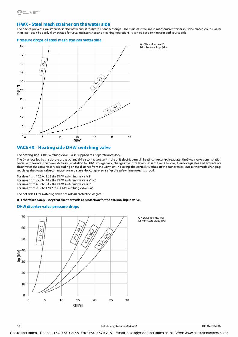
IFWX - Steel mesh strainer on the water sideThe device prevents any impurity in the water circuit to dirt the heat exchanger. The stainless steel mesh mechanical strainer must be placed on the water inlet line. It can be easily dismounted for usual maintenance and cleaning operations. It can be used on the user and source side.
Pressure drops of steel mesh strainer water side
VACSHX - Heating side DHW switching valveThe heating side DHW switching valve is also supplied as a separate accessory.The DHW is called by the closure of the potential-free contact present in the unit electric panel.In heating, the control regulates the 3-way valve commutation because it deviates the flow-rate from installation to DHW storage tank, changes the installation set into the DHW one, thermoregulates and activates or deactivates the compressors depending on the distance from the DHW set. In cooling, the control switches off the compressors due to the mode changing, regulates the 3-way valve commutation and starts the compressors after the safety time owed to on/off.
For sizes from 10.2 to 22.2 the DHW switching valve is 2”.For sizes from 27.2 to 40.2 the DHW switching valve is 2”1/2.For sizes from 43.2 to 80.2 the DHW switching valve is 3”.For sizes from 90.2 to 120.2 the DHW switching valve is 4”.
The hot side DHW switching valve has a IP 40 protection degree.
It is therefore compulsory that client provides a protection for the external liquid valve.
DHW diverter valve pressure drops
Q = Water flow rate [l/s]DP = Pressure drops [kPa]
Q = Water flow rate [l/s]DP = Pressure drops [kPa]
Cooke Industries - Phone:: +64 9 579 2185 Fax: +64 9 579 2181 Email: [email protected] Web: www.cookeindustries.co.nz

BT14G006GB-07 ELFOEnergy Ground Medium2 43
Heating only unit
Performance in Heating - Groundwater versionSize 10.2 - 40.2
Size To °C
Cold side water outlet temperature (°C)
5 7 10 12 15 17
kWt kWe kWt kWe kWt kWe kWt kWe kWt kWe kWt kWe
10.2
30 35,5 5,55 37,4 5,52 40,5 5,48 42,7 5,46 46,4* 5,43* 48,6* 5,41*35 35,0 6,21 36,9 6,18 40,0 6,15 42,1 6,13 45,6* 6,10* 47,8* 6,09*45 33,9 7,79 35,7 7,75 38,5 7,71 40,5 7,67 43,6* 7,63* 45,6* 7,61*55 31,6 10,0 33,1 9,93 35,5 9,83 37,4 9,77 40,1* 9,69* 41,8* 9,65*60 31,1 12,0 32,7 11,9 35,2 11,8 36,8 11,7 39,5* 11,5* 41,1* 11,4*
12.2
30 40,9 6,48 43,2 6,5 46,7 6,54 49,2 6,58 53,4* 6,65* 56,4* 6,70*35 40,4 7,23 42,6 7,26 46,0 7,31 48,5 7,35 52,6* 7,43* 56,0* 7,48*45 39,1 9,10 41,2 9,12 44,7 8,89 46,7 9,17 50,4* 9,23* 52,7* 9,27*55 36,8 11,7 38,6 11,7 41,4 11,7 43,4 11,7 46,6* 11,7* 48,6* 11,7*60 36,7 14,1 38,4 14,0 41,4 14,0 43,3 13,9 46,4* 13,9* 48,4* 13,8*
14.2
30 49,2 7,84 52,0 7,9 56,2 8,00 59,3 8,08 64,4* 8,22* 67,7* 8,32*35 48,6 8,68 51,4 8,74 55,4 8,84 58,4 8,91 63,3* 9,04* 66,6* 9,13*45 46,8 10,8 49,3 10,9 53,4 10,9 56,2 11,0 61,4* 10,7* 64,2* 10,9*55 43,9 13,8 46,0 13,8 49,6 13,9 52,0 13,9 56,0* 14,0* 58,6* 14,0*60 43,9 16,3 46,1 16,3 49,6 16,3 51,6 16,1 56,0* 16,3* 58,6* 16,3*
16.2
30 57,3 9,25 60,6 9,34 65,5 9,42 69,2 9,42 74,9 9,55 78,9 9,6635 56,5 10,1 59,7 10,2 64,5 10,3 68,1 10,4 73,7 10,5 77,6 10,745 54,5 12,4 57,5 12,5 62,1 12,6 65,1 12,6 70,3 12,8 74,0 12,955 51,1 15,8 53,6 15,8 57,5 15,8 60,4 15,8 64,7 15,9 67,9 16,060 50,7 18,9 53,1 18,8 57,0 18,7 59,6 18,7 64,1 18,6 67,3 18,7
19.2
30 67,9 10,8 71,8 10,8 77,8 10,9 82,1 11,0 88,7 11,2 93,4 11,335 67,0 11,8 70,8 11,8 76,6 11,9 80,7 12,0 87,0 12,1 91,8 12,345 64,7 14,5 68,1 14,6 73,2 14,6 77,0 14,7 83,3 14,7 87,5 14,855 59,9 18,5 62,8 18,5 67,3 18,5 70,7 18,5 76,0 18,6 79,8 18,660 58,9 22,0 61,9 22,0 66,4 21,9 69,5 21,9 74,6 21,8 78,3 21,8
22.2
30 79,5 13,0 84,0 13,0 90,7 13,0 95,4 13,0 103 12,9 108 12,835 78,8 14,4 83,1 14,4 89,8 14,5 94,4 14,6 102 14,6 107 14,645 76,2 17,5 80,4 17,6 86,5 17,7 90,8 17,8 97,5 18,0 102 18,055 70,7 21,7 74,1 21,8 79,7 21,9 83,8 21,5 89,6 22,2 93,9 22,360 70,1 25,4 73,5 25,4 78,5 25,4 82,4 25,4 88,5 25,5 92,8 25,6
27.2
30 96,3 15,2 102 15,2 110 15,2 115 15,2 125 15,2 131 15,235 95,1 16,7 100 16,8 108 16,9 114 16,9 123 17,0 129 17,045 91,4 20,6 96,3 20,6 104 20,8 109 20,9 117 21,0 123 21,155 84,1 25,7 88,3 25,8 95,1 25,9 99,3 26,0 107 26,2 112 26,360 82,3 28,9 86,4 28,9 93,0 29,1 97,6 29,1 105 29,3 110 29,4
30.2
30 109 17,5 115 17,5 123 17,4 130 17,3 140 17,0 147 16,935 108 19,4 114 19,5 122 19,6 129 19,6 139 19,6 146 19,545 103 23,6 109 23,8 117 24,0 123 24,2 133 24,3 139 24,555 95,6 29,0 100 29,2 108 29,5 113 29,6 121 30,0 127 30,260 93,8 32,3 98,3 32,4 106 32,6 111 32,8 120 33,1 126 33,3
35.2
30 126 20,5 133 20,5 144 20,7 152 20,7 165 20,8 174 20,835 124 22,4 131 22,6 142 22,8 150 23,0 162 23,1 171 23,245 119 27,1 125 27,3 135 27,6 142 27,8 153 28,1 161 28,355 110 33,7 115 33,9 124 34,2 130 34,5 140 34,8 147 35,060 109 37,8 115 37,9 124 38,2 130 38,4 140 38,7 147 38,9
40.2
30 143 23,3 151 23,4 163 23,6 171 23,6 186 23,7 195 23,735 141 25,5 148 25,7 161 25,9 169 26,0 183 26,2 192 26,345 135 30,9 142 31,1 153 31,3 161 31,5 173 31,8 182 31,955 125 38,1 131 38,3 141 38,6 148 38,8 159 39,1 166 39,360 123 42,5 129 42,6 139 42,8 146 43,0 157 43,3 164 43,5
kWt = Heating capacity (kW)kWe = Total Electrical power absorbed (compressor + Auxiliary Circuit)(kW)To = Water outlet temperature hot side (°C)The performances are referred to DeltaT=5°C on both the hot and cold sides* Performance with modulating valve or control inverter pump cold side (optional configurations)
Cooke Industries - Phone:: +64 9 579 2185 Fax: +64 9 579 2181 Email: [email protected] Web: www.cookeindustries.co.nz

44 ELFOEnergy Ground Medium2 BT14G006GB-07
Size To °C
Cold side water outlet temperature (°C)
5 7 10 12 15 17
kWt kWe kWt kWe kWt kWe kWt kWe kWt kWe kWt kWe
43.2
30 157 26,2 166 26,4 180 26,7 190 27,0 206 27,4 217 27,635 155 28,4 163 28,7 176 29,0 186 29,2 202 29,6 212 29,945 148 34,4 156 34,5 168 34,9 177 35,1 191 35,5 200 35,755 138 42,8 145 42,9 156 43,2 163 43,5 176 43,9 184 44,160 137 47,5 143 46,8 154 48,3 162 48,5 175 48,8 183 49,0
45.2
30 170 27,6 179 27,7 194 28,0 205 28,1 222 28,2 233 28,335 167 30,1 176 30,3 191 30,7 201 30,9 218 31,2 229 31,345 160 36,5 168 36,7 182 37,1 191 37,4 207 37,8 217 38,155 148 45,3 155 45,5 166 45,9 175 46,2 188 46,6 197 47,060 147 50,5 154 50,7 165 51,1 174 51,3 187 51,9 197 52,2
50.2
30 185 30,2 195 30,4 212 30,9 224 31,2 244 31,6 256 31,935 182 32,7 192 32,9 208 33,4 220 33,7 238 34,2 251 34,545 174 39,5 183 39,7 197 40,1 208 40,4 226 40,9 237 41,355 161 49,3 169 49,5 182 49,8 191 50,1 206 50,7 215 51,160 160 55,3 167 55,4 180 55,7 189 56,0 204 56,5 214 56,9
55.2
30 201 33,3 212 33,5 230 33,9 243 34,3 263 34,7 277 35,135 197 36,1 208 36,3 225 36,8 238 37,1 258 37,6 271 38,045 190 43,6 199 43,9 215 44,3 227 44,6 244 45,1 256 45,455 176 54,2 185 54,5 198 54,8 208 55,1 224 55,6 234 56,060 175 60,5 182 60,7 196 61,0 206 61,3 221 61,7 232 62,1
60.2
30 225 35,9 238 36,2 259 36,6 273 37,0 296 37,4 313 37,835 220 40,3 232 40,6 252 41,1 267 41,6 289 42,2 305 42,645 216 48,7 228 49,1 245 49,5 259 49,9 279 50,5 292 50,955 202 60,7 212 61,0 227 61,4 238 61,8 256 62,5 268 62,960 199 68,1 209 68,4 224 68,7 235 69,1 252 69,7 265 70,1
70.2
30 256 42,7 271 43,2 294 44,0 310 44,6 336 45,6 353 46,235 252 46,0 267 46,5 289 47,3 305 47,9 330 48,8 347 49,545 243 55,4 256 55,8 276 56,5 290 57,0 314 57,9 330 58,655 225 68,4 236 68,8 253 69,4 266 69,9 286 70,9 300 71,560 223 76,1 233 76,5 250 77,1 263 77,5 283 78,4 297 78,9
80.2
30 290 48,2 306 48,9 332 50,0 350 50,9 380 52,3 400 53,235 285 52,0 301 52,7 326 53,8 344 54,7 372 56,0 391 56,845 274 62,4 288 63,0 311 63,9 327 64,6 352 65,8 370 66,555 253 76,5 266 77,1 285 78,0 299 78,6 323 79,7 339 80,460 251 84,6 263 85,2 283 86,1 297 86,7 320 87,7 335 88,3
90.2
30 326 54,2 344 54,6 372 55,2 392 55,6 425 56,3 446 56,735 321 59,0 339 59,4 367 60,1 386 60,6 418 61,3 439 61,845 310 71,7 327 72,1 351 72,6 369 73,1 397 73,8 415 74,255 288 89,9 302 90,2 323 90,6 339 91,0 364 91,6 380 92,060 287 101 299 101 320 102 335 102 360 103 377 103
100.2
30 357 60,7 375 61,3 404 62,1 425 62,8 460 63,9 483 64,735 352 66,0 370 66,6 398 67,5 419 68,2 452 69,3 475 70,045 338 79,9 354 80,4 379 81,2 398 81,8 429 82,7 450 83,455 312 99,6 326 100 350 101 367 101 393 102 411 10260 311 112 325 112 348 112 365 113 392 114 410 114
120.2
30 422 72,4 443 72,8 475 73,5 500 74,0 540 74,9 566 75,435 416 79,1 436 79,6 469 80,4 492 80,9 531 81,8 556 82,445 400 96,4 419 96,8 449 97,4 471 97,9 507 98,7 531 99,255 370 122 386 122 412 122 434 122 463 123 483 12360 370 137 386 137 413 138 433 138 464 138 485 138
kWt = Heating capacity (kW)kWe = Total Electrical power absorbed (compressor + Auxiliary Circuit)(kW)To = Water outlet temperature hot side (°C)The performances are referred to DeltaT=5°C on both the hot and cold side
Heating only unit
Performance in Heating - Groundwater versionSize 43.2 - 120.2
Cooke Industries - Phone:: +64 9 579 2185 Fax: +64 9 579 2181 Email: [email protected] Web: www.cookeindustries.co.nz

BT14G006GB-07 ELFOEnergy Ground Medium2 45
Cooling only unitPerformances in cooling - Groundwater versionSize 10.2 - 35.2
Size To (°C)
Hot side water outlet temperature (°C)
30 35 40 45 50
kWf kWe kWf kWe kWf kWe kWf kWe kWf kWe
10.2
5 30,2 5,48 29,0 6,15 27,6 6,98 25,9 7,79 23,6 8,907 32,2 5,45 31,0 6,12 29,4 6,95 27,7 7,75 25,3 8,84
10 35,1 5,41 33,8 6,08 32,0 6,91 30,2 7,71 27,7 8,7712 36,8 5,39 35,5 6,07 33,9 6,88 31,9 7,67 29,4 8,7215 40,3 5,36 38,8 6,05 36,9 6,85 34,9 7,63 32,2 8,6618 43,7 5,33 42,2 6,02 39,9 6,82 37,9 7,59 35,0 8,60
12.2
5 34,7 6,38 33,5 7,16 31,7 8,13 29,8 9,10 27,3 10,47 37,0 6,40 35,6 7,18 33,8 8,15 31,8 9,12 29,2 10,4
10 40,1 6,45 38,6 7,23 36,9 8,19 35,2 8,89 32,2 10,312 42,3 6,55 40,7 7,35 38,8 8,30 36,5 9,26 33,7 10,515 45,7 6,62 44,2 7,43 42,0 8,37 39,7 9,32 36,6 10,618 49,7 6,70 48,0 7,52 45,6 8,45 43,2 9,39 39,9 10,6
14.2
5 41,8 7,69 40,2 8,59 38,0 9,70 36,0 10,7 32,9 12,27 44,6 7,76 42,9 8,65 40,6 9,74 38,8 10,6 35,3 12,2
10 48,2 7,86 46,5 8,75 44,3 9,83 41,7 11,0 38,4 12,412 50,9 8,03 48,9 8,91 46,6 9,98 43,9 11,1 40,5 12,615 55,0 8,16 53,1 9,04 50,7 10,1 48,9 10,8 44,6 12,518 59,8 8,30 57,7 9,18 55,3 10,2 52,8 11,1 48,5 12,6
16.2
5 48,5 9,24 46,7 10,0 44,3 11,3 41,7 12,4 38,3 14,17 51,8 9,53 49,9 10,1 47,4 11,3 44,6 12,5 41,0 14,1
10 56,2 9,53 54,1 10,2 51,4 11,4 48,7 12,6 44,8 14,212 59,3 9,36 57,0 10,4 54,1 11,6 51,1 12,7 47,2 14,415 64,7 9,52 62,2 10,5 59,1 11,7 55,7 12,9 51,5 14,518 70,2 9,67 67,4 10,7 64,1 11,9 60,3 13,1 55,8 14,6
19.2
5 57,7 10,6 55,7 11,7 52,8 13,1 49,7 14,5 45,3 16,57 61,6 10,6 59,4 11,7 56,5 13,1 53,2 14,6 48,5 16,5
10 66,8 10,7 64,5 11,8 61,1 13,2 57,6 14,6 52,7 16,612 70,2 10,9 67,9 12,0 64,3 13,4 60,7 14,8 55,7 16,815 76,7 11,1 74,0 12,2 70,2 13,5 66,4 14,9 60,9 16,818 83,2 11,3 80,2 12,3 76,1 13,6 72,0 15,0 66,2 16,9
22.2
5 66,9 13,0 64,5 14,4 61,2 16,0 57,3 17,7 52,6 19,97 71,5 13,0 68,8 14,5 65,4 16,1 61,2 17,8 56,2 20,0
10 77,2 13,0 74,6 14,6 70,8 16,3 66,8 18,0 61,2 20,112 81,1 13,2 78,2 14,8 74,7 16,5 70,2 18,3 64,4 20,415 88,4 13,1 85,1 14,9 81,3 16,6 76,6 18,4 70,5 20,618 95,6 13,0 92,0 14,9 87,9 16,7 82,9 18,6 76,5 20,8
27.2
5 82,2 15,0 79,0 16,7 75,1 18,7 70,3 20,8 64,1 23,4
7 87,4 15,1 84,2 16,8 80,1 18,8 75,1 20,9 68,5 23,5
10 94,6 15,1 91,2 16,9 86,7 18,9 81,5 21,0 74,7 23,6
12 99,7 15,1 95,8 16,9 91,5 19,0 85,8 21,1 78,5 23,7
15 108 15,1 104 17,0 99,7 19,0 93,5 21,2 85,8 23,9
18 117 15,0 113 17,0 108 19,1 101 21,4 93,1 24,0
30.2
5 92,4 17,2 89,0 19,2 84,6 21,4 79,1 23,6 72,5 26,3
7 98,5 17,2 94,8 19,3 90,1 21,5 84,3 23,8 77,3 26,5
10 106 17,1 102 19,4 97,7 21,7 91,7 24,0 84,2 26,7
12 112 17,2 108 19,6 103 22,0 96,5 24,4 88,6 27,2
15 122 16,9 117 19,5 112 22,0 105 24,6 96,7 27,4
18 132 16,6 127 19,5 121 22,1 114 24,8 105 27,7
35.2
5 107 20,1 102 22,2 97,2 24,5 90,7 27,1 83,0 30,4
7 114 20,2 109 22,4 104 24,7 96,7 27,3 88,6 30,6
10 124 20,3 118 22,6 113 25,0 106 27,6 96,9 30,9
12 131 20,6 125 23,0 119 25,4 111 28,1 102 31,5
15 143 20,6 137 23,1 130 25,6 121 28,4 111 31,8
18 154 20,7 148 23,3 141 25,8 131 28,7 121 32,1
kWf = Cooling capacity in kWkWe = Total Electrical power absorbed (compressor + Auxiliary Circuit)(kW)
To = Water outlet temperature cold side (°C)The performances are referred to DeltaT=5°C on both the hot and cold sides
Cooke Industries - Phone:: +64 9 579 2185 Fax: +64 9 579 2181 Email: [email protected] Web: www.cookeindustries.co.nz

46 ELFOEnergy Ground Medium2 BT14G006GB-07
Size To (°C)
Hot side water outlet temperature (°C)
30 35 40 45 50
kWf kWe kWf kWe kWf kWe kWf kWe kWf kWe
40.2
5 121 22,9 116 25,3 110 28,0 103 30,9 94,8 34,57 129 23,0 124 25,4 118 28,2 110 31,1 101 34,7
10 139 23,1 134 25,6 127 28,4 120 31,3 110 3512 147 23,4 141 26,0 135 28,8 126 31,8 116 35,515 160 23,5 154 26,1 147 29,0 137 32,1 127 35,818 173 23,5 167 26,3 159 29,2 149 32,4 137 36,1
43.2
5 132 25,7 127 28,1 121 31,1 113 34,4 104 38,67 141 25,9 136 28,4 129 31,3 121 34,5 111 38,7
10 153 26,2 147 28,7 140 31,6 131 34,9 120 39,112 161 26,7 155 29,2 147 32,1 138 35,5 127 39,715 176 27,1 169 29,6 161 32,5 151 35,8 139 40,118 192 27,5 184 30,0 175 32,8 164 36,2 151 40,4
45.2
5 144 27,0 138 29,8 131 33,0 123 36,5 112 40,97 153 27,2 147 30,0 140 33,2 131 36,7 120 41,1
10 166 27,4 160 30,4 152 33,5 142 37,1 130 41,512 175 27,8 169 30,9 160 34,1 150 37,8 138 42,215 191 28,0 184 31,2 175 34,4 164 38,2 150 42,618 207 28,2 199 31,4 190 34,8 177 38,6 163 43,1
50.2
5 156 29,5 150 32,4 142 35,8 133 39,5 122 44,47 167 29,8 160 32,6 152 36,0 142 39,7 131 44,6
10 182 30,2 174 33,1 166 36,4 155 40,1 142 45,012 191 30,8 184 33,7 175 37,0 163 40,8 150 45,715 209 31,3 200 34,2 191 37,5 178 41,2 164 46,218 227 31,8 217 34,7 207 38,0 193 41,6 178 46,7
55.2
5 169 32,5 162 35,7 154 39,5 145 43,6 133 48,97 181 32,8 173 36,0 165 39,7 154 43,9 142 49,2
10 195 33,2 188 36,4 179 40,1 168 44,3 154 49,612 207 33,9 199 37,1 189 40,8 177 45,0 163 50,315 226 34,4 217 37,6 206 41,3 193 45,5 178 50,918 244 34,9 235 38,1 224 41,7 209 46,0 193 51,4
60.2
5 193 36,7 185 40,3 175 44,5 164 49,3 150 55,37 206 37,0 197 40,6 188 44,8 175 49,6 160 55,6
10 223 37,6 214 41,2 203 45,3 190 50,0 174 56,112 235 38,3 225 42,0 214 46,1 200 51,0 184 57,115 257 38,9 246 42,6 234 46,7 219 51,6 201 57,718 279 39,5 267 43,2 254 47,3 237 52,2 219 58,4
kWf = Potenza frigorifera in kW
kWf = Cooling capacity in kWkWe = Total Electrical power absorbed (compressor + Auxiliary Circuit)(kW)To = Water outlet temperature cold side (°C)The performances are referred to DeltaT=5°C on both the hot and cold sides
Cooling only unit
Performances in cooling - Groundwater versionSize 40.2 - 60.2
Cooke Industries - Phone:: +64 9 579 2185 Fax: +64 9 579 2181 Email: [email protected] Web: www.cookeindustries.co.nz

BT14G006GB-07 ELFOEnergy Ground Medium2 47
Size To (°C)
Hot side water outlet temperature (°C)
30 35 40 45 50
kWf kWe kWf kWe kWf kWe kWf kWe kWf kWe
70.2
5 216 41,7 208 45,6 198 50,3 186 55,4 171 61,97 231 42,2 222 46,0 212 50,7 198 55,8 182 62,3
10 250 42,9 241 46,8 229 51,4 216 56,5 198 63,012 264 44,0 254 47,9 241 52,4 226 57,6 208 64,115 287 45,0 277 48,9 263 53,3 247 58,5 227 65,018 311 45,9 299 49,8 285 54,2 267 59,4 246 65,9
80.2
5 244 47,2 235 51,5 223 56,7 210 62,4 192 69,47 259 47,8 250 52,2 238 57,3 223 63,0 205 70,0
10 283 49,0 272 53,3 259 58,2 242 63,9 223 70,912 297 50,4 286 54,7 273 59,5 255 65,3 235 72,315 323 51,8 311 56,0 297 60,7 278 66,4 256 73,418 349 53,2 337 57,4 321 61,9 301 67,6 278 74,5
90.2
5 276 53,1 264 58,4 253 64,6 236 71,7 216 80,87 294 53,5 281 58,8 269 65,0 252 72,1 231 81,1
10 319 54,1 306 59,5 292 65,5 274 72,6 251 81,612 333 55,0 321 60,6 306 66,6 288 73,8 264 82,915 364 55,7 350 61,4 334 67,3 313 74,5 288 83,518 394 56,4 380 62,1 362 68,0 339 75,2 311 84,2
100.2
5 300 60,1 289 66,0 275 72,4 257 79,9 235 89,87 319 60,7 306 66,6 291 72,9 273 80,4 249 90,2
10 343 61,7 331 67,5 315 73,8 295 81,2 271 90,912 360 63,1 347 68,9 330 75,2 310 82,6 285 92,415 392 64,2 377 70,0 360 76,3 337 83,6 310 93,318 423 65,4 408 71,2 389 77,4 365 84,6 336 94,2
120.2
5 351 72,3 337 79,5 321 87,3 300 97,0 273 1107 371 72,8 357 80,0 340 87,8 318 97,3 290 110
10 401 73,5 388 80,8 370 88,6 345 97,9 315 11012 421 74,8 407 82,2 387 90,0 362 99,4 333 11215 458 75,7 441 83,2 421 90,9 395 100 363 11318 494 76,6 476 84,1 455 91,8 427 101 393 113
kWf = Cooling capacity in kWkWe = Total Electrical power absorbed (compressor + Auxiliary Circuit)(kW)To = Water outlet temperature cold side (°C)The performances are referred to DeltaT=5°C on both the hot and cold sides
Cooling only unit
Performances in cooling - Groundwater versionSize 70.2 - 120.2
Cooke Industries - Phone:: +64 9 579 2185 Fax: +64 9 579 2181 Email: [email protected] Web: www.cookeindustries.co.nz
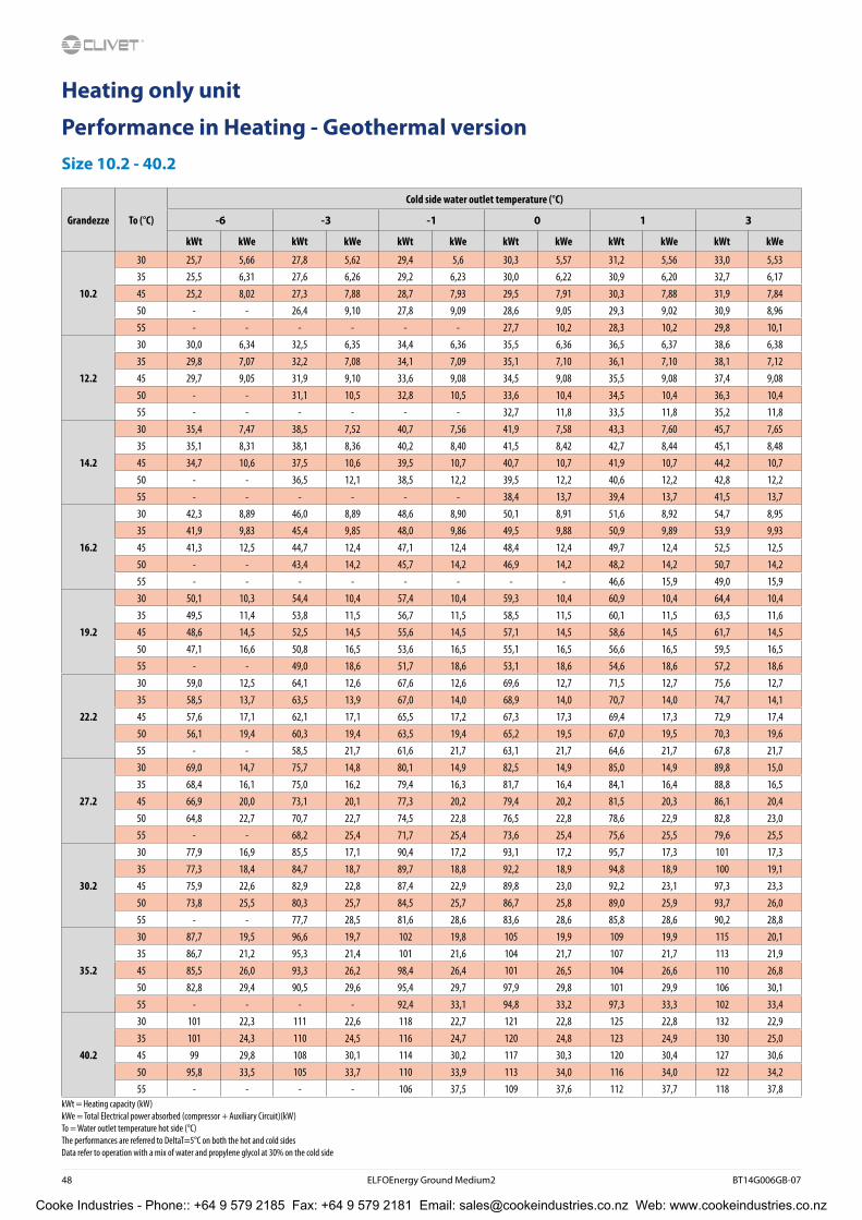
48 ELFOEnergy Ground Medium2 BT14G006GB-07
Grandezze To (°C)
Cold side water outlet temperature (°C)
-6 -3 -1 0 1 3
kWt kWe kWt kWe kWt kWe kWt kWe kWt kWe kWt kWe
10.2
30 25,7 5,66 27,8 5,62 29,4 5,6 30,3 5,57 31,2 5,56 33,0 5,5335 25,5 6,31 27,6 6,26 29,2 6,23 30,0 6,22 30,9 6,20 32,7 6,1745 25,2 8,02 27,3 7,88 28,7 7,93 29,5 7,91 30,3 7,88 31,9 7,8450 - - 26,4 9,10 27,8 9,09 28,6 9,05 29,3 9,02 30,9 8,9655 - - - - - - 27,7 10,2 28,3 10,2 29,8 10,1
12.2
30 30,0 6,34 32,5 6,35 34,4 6,36 35,5 6,36 36,5 6,37 38,6 6,3835 29,8 7,07 32,2 7,08 34,1 7,09 35,1 7,10 36,1 7,10 38,1 7,1245 29,7 9,05 31,9 9,10 33,6 9,08 34,5 9,08 35,5 9,08 37,4 9,0850 - - 31,1 10,5 32,8 10,5 33,6 10,4 34,5 10,4 36,3 10,455 - - - - - - 32,7 11,8 33,5 11,8 35,2 11,8
14.2
30 35,4 7,47 38,5 7,52 40,7 7,56 41,9 7,58 43,3 7,60 45,7 7,6535 35,1 8,31 38,1 8,36 40,2 8,40 41,5 8,42 42,7 8,44 45,1 8,4845 34,7 10,6 37,5 10,6 39,5 10,7 40,7 10,7 41,9 10,7 44,2 10,750 - - 36,5 12,1 38,5 12,2 39,5 12,2 40,6 12,2 42,8 12,255 - - - - - - 38,4 13,7 39,4 13,7 41,5 13,7
16.2
30 42,3 8,89 46,0 8,89 48,6 8,90 50,1 8,91 51,6 8,92 54,7 8,9535 41,9 9,83 45,4 9,85 48,0 9,86 49,5 9,88 50,9 9,89 53,9 9,9345 41,3 12,5 44,7 12,4 47,1 12,4 48,4 12,4 49,7 12,4 52,5 12,550 - - 43,4 14,2 45,7 14,2 46,9 14,2 48,2 14,2 50,7 14,255 - - - - - - - - 46,6 15,9 49,0 15,9
19.2
30 50,1 10,3 54,4 10,4 57,4 10,4 59,3 10,4 60,9 10,4 64,4 10,435 49,5 11,4 53,8 11,5 56,7 11,5 58,5 11,5 60,1 11,5 63,5 11,645 48,6 14,5 52,5 14,5 55,6 14,5 57,1 14,5 58,6 14,5 61,7 14,550 47,1 16,6 50,8 16,5 53,6 16,5 55,1 16,5 56,6 16,5 59,5 16,555 - - 49,0 18,6 51,7 18,6 53,1 18,6 54,6 18,6 57,2 18,6
22.2
30 59,0 12,5 64,1 12,6 67,6 12,6 69,6 12,7 71,5 12,7 75,6 12,735 58,5 13,7 63,5 13,9 67,0 14,0 68,9 14,0 70,7 14,0 74,7 14,145 57,6 17,1 62,1 17,1 65,5 17,2 67,3 17,3 69,4 17,3 72,9 17,450 56,1 19,4 60,3 19,4 63,5 19,4 65,2 19,5 67,0 19,5 70,3 19,655 - - 58,5 21,7 61,6 21,7 63,1 21,7 64,6 21,7 67,8 21,7
27.2
30 69,0 14,7 75,7 14,8 80,1 14,9 82,5 14,9 85,0 14,9 89,8 15,035 68,4 16,1 75,0 16,2 79,4 16,3 81,7 16,4 84,1 16,4 88,8 16,545 66,9 20,0 73,1 20,1 77,3 20,2 79,4 20,2 81,5 20,3 86,1 20,450 64,8 22,7 70,7 22,7 74,5 22,8 76,5 22,8 78,6 22,9 82,8 23,055 - - 68,2 25,4 71,7 25,4 73,6 25,4 75,6 25,5 79,6 25,5
30.2
30 77,9 16,9 85,5 17,1 90,4 17,2 93,1 17,2 95,7 17,3 101 17,335 77,3 18,4 84,7 18,7 89,7 18,8 92,2 18,9 94,8 18,9 100 19,145 75,9 22,6 82,9 22,8 87,4 22,9 89,8 23,0 92,2 23,1 97,3 23,350 73,8 25,5 80,3 25,7 84,5 25,7 86,7 25,8 89,0 25,9 93,7 26,055 - - 77,7 28,5 81,6 28,6 83,6 28,6 85,8 28,6 90,2 28,8
35.2
30 87,7 19,5 96,6 19,7 102 19,8 105 19,9 109 19,9 115 20,135 86,7 21,2 95,3 21,4 101 21,6 104 21,7 107 21,7 113 21,945 85,5 26,0 93,3 26,2 98,4 26,4 101 26,5 104 26,6 110 26,850 82,8 29,4 90,5 29,6 95,4 29,7 97,9 29,8 101 29,9 106 30,155 - - - - 92,4 33,1 94,8 33,2 97,3 33,3 102 33,4
40.2
30 101 22,3 111 22,6 118 22,7 121 22,8 125 22,8 132 22,935 101 24,3 110 24,5 116 24,7 120 24,8 123 24,9 130 25,045 99 29,8 108 30,1 114 30,2 117 30,3 120 30,4 127 30,650 95,8 33,5 105 33,7 110 33,9 113 34,0 116 34,0 122 34,255 - - - - 106 37,5 109 37,6 112 37,7 118 37,8
kWt = Heating capacity (kW)kWe = Total Electrical power absorbed (compressor + Auxiliary Circuit)(kW)To = Water outlet temperature hot side (°C)The performances are referred to DeltaT=5°C on both the hot and cold sidesData refer to operation with a mix of water and propylene glycol at 30% on the cold side
Heating only unit
Performance in Heating - Geothermal versionSize 10.2 - 40.2
Cooke Industries - Phone:: +64 9 579 2185 Fax: +64 9 579 2181 Email: [email protected] Web: www.cookeindustries.co.nz

BT14G006GB-07 ELFOEnergy Ground Medium2 49
Grandezze To (°C)
Cold side water outlet temperature (°C)
-6 -3 -1 0 1 3
kWt kWe kWt kWe kWt kWe kWt kWe kWt kWe kWt kWe
43.2
30 111 24,9 122 25,2 130 25,3 133 25,4 138 25,5 146 25,735 110 27,1 121 27,3 127 27,5 131 27,5 136 27,6 143 27,845 109 33,3 119 33,5 125 33,7 128 33,7 132 33,8 139 34,050 - - 115 37,7 121 37,9 124 37,9 128 38,0 135 38,255 - - - - 117 42,1 120 42,1 124 42,2 130 42,4
45.2
30 119 26,2 131 26,5 138 26,6 142 26,7 147 26,8 155 27,035 118 28,6 129 28,9 137 29,0 141 29,1 145 29,2 153 29,445 117 35,4 127 35,5 134 35,6 137 35,7 141 35,8 149 36,150 114 39,9 123 40,0 130 40,1 133 40,2 137 40,3 144 40,555 - - - - 126 44,6 129 44,6 132 44,7 139 44,9
50.2
30 129 28,6 142 28,9 150 29,1 155 29,2 160 29,3 169 29,535 127 31,1 140 31,3 148 31,5 152 31,6 157 31,7 166 31,945 126 38,4 137 38,6 145 38,7 149 38,8 153 38,9 161 39,150 - - 134 43,5 141 43,6 145 43,7 148 43,8 156 44,055 - - - - 137 48,6 140 48,6 144 48,7 151 48,9
55.2
30 143 31,6 156 31,9 166 32,1 171 32,2 176 32,3 186 32,535 142 34,4 155 34,7 164 34,9 168 35,0 173 35,1 183 35,345 140 42,5 152 42,7 160 42,8 165 42,9 169 43,1 179 43,350 - - 148 48,0 156 48,1 159 48,2 164 48,3 173 48,555 - - - - 151 53,5 154 53,6 159 53,6 166 53,8
60.2
30 160 35,4 175 35,8 185 36,0 191 36,1 197 36,3 208 36,635 159 38,7 173 39,0 183 39,2 188 39,3 194 39,5 205 39,845 157 48,1 170 48,2 179 48,2 184 48,4 189 48,5 200 48,850 - - 166 54,3 174 54,4 179 54,5 184 54,6 193 54,855 - - - - 169 60,6 174 60,6 178 60,7 187 60,9
70.2
30 181 39,7 198 40,2 209 40,5 215 40,7 222 40,9 235 41,335 180 43,2 196 43,7 207 44,0 213 44,2 219 44,4 231 44,845 178 53,3 192 53,7 203 54,0 208 54,1 214 54,3 226 54,750 - - 187 60,1 197 60,4 202 60,6 208 60,8 218 61,255 - - - - 191 66,9 196 67,1 201 67,3 211 67,6
80.2
30 202 44,1 220 44,8 233 45,3 239 45,6 247 45,8 260 46,435 200 48,0 218 48,7 231 49,2 236 49,5 243 49,7 257 50,245 198 58,9 214 59,7 226 60,2 231 60,4 238 60,6 251 61,250 - - 208 66,6 219 67,1 224 67,4 230 67,6 242 68,255 - - - - 212 74,1 218 74,4 223 74,7 234 75,2
90.2
30 229 51,6 248 52,0 262 52,3 269 52,5 276 52,6 292 52,935 228 56,2 246 56,7 260 57,0 267 57,2 274 57,3 289 57,645 225 69,9 243 70,2 256 70,4 261 70,5 269 70,7 283 71,050 - - 236 79,6 249 79,7 254 79,8 261 79,9 274 80,255 - - - - 241 89,1 247 89,1 252 89,2 265 89,4
100.2
30 247 56,7 267 57,3 282 57,7 290 57,9 298 58,2 314 58,635 245 61,5 265 62,1 279 62,6 288 62,8 295 63,0 311 63,545 243 76,1 262 76,6 276 77,0 282 77,2 290 77,5 304 77,950 - - 254 86,5 267 86,9 273 87,1 281 87,3 295 87,755 - - - - 259 96,8 265 97,0 272 97,2 285 97,6
120.2
30 290 69,0 313 69,5 331 70,0 340 70,1 348 70,3 367 70,735 289 74,9 312 75,5 329 76,0 337 76,2 346 76,4 365 76,945 287 93,3 308 93,8 324 94,2 333 94,4 340 94,6 357 94,950 - - 299 107 314 107 323 107 330 107 346 10855 - - - - 304 120 313 120 320 120 335 121
kWt = Heating capacity (kW)kWe = Total Electrical power absorbed (compressor + Auxiliary Circuit)(kW)To = Water outlet temperature hot side (°C)The performances are referred to DeltaT=5°C on both the hot and cold sidesData refer to operation with a mix of water and propylene glycol at 30% on the cold side
Heating only unit
Performance in Heating - Geothermal versionSize 43.2 - 120.2
Cooke Industries - Phone:: +64 9 579 2185 Fax: +64 9 579 2181 Email: [email protected] Web: www.cookeindustries.co.nz

50 ELFOEnergy Ground Medium2 BT14G006GB-07
Dimensional - Standard and Geothermic version without hydronic unit
Sizes 10.2 - 22.2
1. Compressor compartment
2. Electrical panel
3. Unit control keypad
4. Power input
5. Hot side water return (1” 1/4 GAS)
6. Hot side water supply (1” 1/4 GAS)
7. Cold side water return (1” 1/4 GAS)
8. Cold side water supply (1” 1/4 GAS)
9. Functional spaces
10. Vibration damper mounts Ø 12,5
11. Partial recovery water return (1” 1/4 Victaulic)
12. Partial recovery water supply (1” 1/4 Victaulic)
Size 10.2 12.2 14.2 16.2 19.2 22.2
Length mm 837 837 837 837 837 837
Height mm 1483 1483 1483 1483 1483 1483
Depth mm 607 607 607 607 607 607
Operating weight - standard kg 212 212 225 276 295 308
Shipping weight - standard kg 206 206 216 263 277 295
Operating weight - Geothermic kg 218 218 225 287 302 315
Shipping weight - Geothermic kg 210 210 216 270 282 300
The presence of optional accessories may result in a substantial variation of the weights shown in the table.
DAA8P10 2_22 2 STD REV00
Cooke Industries - Phone:: +64 9 579 2185 Fax: +64 9 579 2181 Email: [email protected] Web: www.cookeindustries.co.nz

BT14G006GB-07 ELFOEnergy Ground Medium2 51
Dimensional - Standard and Geothermic version with hydronic unit option and oversize enclosure (MOBMAG)
Sizes 10.2 - 22.2
1. Compressor compartment
2. Electrical panel
3. Unit control keypad
4. Power input
5. Hot side water return (2” Victaulic)
6. Hot side water supply (2” Victaulic)
7. Cold side water return (2” Victaulic)
8. Cold side water supply (2” Victaulic)
9. Functional spaces
10. Vibration damper mounts Ø 12,5
11. Hot side water return without pumps (2” Victaulic)
12. Cold side water return without pumps (2” Victaulic)
13. Partial recovery water return (1” 1/4 Victaulic)
14. Partial recovery water supply (1” 1/4 Victaulic)
Size 10.2 12.2 14.2 16.2 19.2 22.2
Length mm 837 837 837 837 837 837
Height mm 1483 1483 1483 1483 1483 1483
Depth mm 961 961 961 961 961 961
Operating weight - standard kg 285 285 301 352 372 385
Shipping weight - standard kg 268 268 281 328 342 360
Operating weight - Geothermic kg 292 292 301 363 379 392
Shipping weight - Geothermic kg 272 272 281 335 347 365
The weights refer to the unit equipped with the following options: cold side hydronic unit VARYFLOW+ (VARYC), hot side hydronic unit VARYFLOW+ (VARYH), oversize enclosure (MOBMAG)The presence of optional accessories may result in a substantial variation of the weights shown in the table.
DAA8P10 2_22 2 MAG REV00
Cooke Industries - Phone:: +64 9 579 2185 Fax: +64 9 579 2181 Email: [email protected] Web: www.cookeindustries.co.nz

52 ELFOEnergy Ground Medium2 BT14G006GB-07
Dimensional - Standard and Geothermic version without hydronic unit
Sizes 27.2 - 60.2
1. Compressor compartment
2. Electrical panel
3. Unit control keypad
4. Power input
5. Hot side water return (2” 1/2 Victaulic)
6. Hot side water supply (2” 1/2 Victaulic)
7. Cold side water return (2” 1/2 Victaulic)
8. Cold side water supply (2” 1/2 Victaulic)
9. Functional spaces
10. Vibration damper mounts Ø 12,5
11. Partial recovery water return (2” Victaulic)
12. Partial recovery water supply (2” Victaulic)
Size 27.2 30.2 35.2 40.2 43.2 45.2 50.2 55.2 60.2
Length mm 1110 1110 1110 1110 1110 1110 1110 1110 1110
Height mm 1910 1910 1910 1910 1910 1910 1910 1910 1910
Depth mm 885 885 885 885 885 885 885 885 885
Operating weight - standard kg 421 424 510 557 622 572 670 700 733
Shipping weight - standard kg 418 421 505 548 613 560 653 683 717
Operating weight - Geothermic kg 452 455 529 594 659 607 705 757 772
Shipping weight - Geothermic kg 442 445 520 576 642 587 680 728 748
The presence of optional accessories may result in a substantial variation of the weights shown in the table.
DAA8P27 2_60 2 STD REV01
Cooke Industries - Phone:: +64 9 579 2185 Fax: +64 9 579 2181 Email: [email protected] Web: www.cookeindustries.co.nz

BT14G006GB-07 ELFOEnergy Ground Medium2 53
Dimensional - Version standard with hydronic unit option and oversize enclosure (MOBMAG)Sizes 27.2 - 60.2
1. Compressor compartment
2. Electrical panel
3. Unit control keypad
4. Power input
5. Hot side water return (3” Victaulic)
6. Hot side water supply (3” Victaulic)
7. Cold side water return (3” Victaulic)
8. Cold side water supply (3” Victaulic)
9. Functional spaces
10. Vibration damper mounts Ø 12,5
11. Partial recovery water return (2” Victaulic)
12. Partial recovery water supply (2” Victaulic)
13. Hot side water return without pumps (3” Victaulic)
14. Cold side water return without pumps (3” Victaulic)
Size 27.2 30.2 35.2 40.2 43.2 45.2 50.2 55.2 60.2
Length mm 1110 1110 1110 1110 1110 1110 1110 1110 1110
Height mm 1910 1910 1910 1910 1910 1910 1910 1910 1910
Depth mm 1390 1390 1390 1390 1390 1390 1390 1390 1390
Operating weight kg 567 570 656 710 792 743 840 878 911
Shipping weight kg 534 537 621 672 738 685 778 816 850
The weights refer to the unit equipped with the following options: cold side hydronic unit VARYFLOW+ (VARYC), hot side hydronic unit VARYFLOW+ (VARYH), oversize enclosure (MOBMAG)The presence of optional accessories may result in a substantial variation of the weights shown in the table.
DAA8P27 2_60 2 MAG REV01
Cooke Industries - Phone:: +64 9 579 2185 Fax: +64 9 579 2181 Email: [email protected] Web: www.cookeindustries.co.nz

54 ELFOEnergy Ground Medium2 BT14G006GB-07
Dimensional - Geothermic version with hydronic unit option and oversize enclosure (MOBMAG)
Size 27.2 - 50.2
1. Compressor compartment
2. Electrical panel
3. Unit control keypad
4. Power input
5. Hot side water return (3” Victaulic)
6. Hot side water supply (3” Victaulic)
7. Cold side water return (3” Victaulic)
8. Cold side water supply (3” Victaulic)
9. Functional spaces
10. Vibration damper mounts Ø 12,5
11. Partial recovery water return (2” Victaulic)
12. Partial recovery water supply (2” Victaulic)
13. Hot side water return without pumps (3” Victaulic)
14. Cold side water return without pumps (3” Victaulic)
Size 27.2 30.2 35.2 40.2 43.2 45.2 50.2
Length mm 1110 1110 1110 1110 1110 1110 1110
Height mm 1910 1910 1910 1910 1910 1910 1910
Depth mm 1390 1390 1390 1390 1390 1390 1390
Operating weight kg 597 600 675 747 829 778 875
Shipping weight kg 558 561 636 700 767 712 805
The weights refer to the unit equipped with the following options: cold side hydronic unit VARYFLOW+ (VARYC), hot side hydronic unit VARYFLOW+ (VARYH), oversize enclosure (MOBMAG)The presence of optional accessories may result in a substantial variation of the weights shown in the table.
DAA8P27 2_50 2 MAG_GEO REV01
Cooke Industries - Phone:: +64 9 579 2185 Fax: +64 9 579 2181 Email: [email protected] Web: www.cookeindustries.co.nz

BT14G006GB-07 ELFOEnergy Ground Medium2 55
Dimensional - Version standard and geothermic without hydronic unit
Size 70.2 - 90.2
1. Compressor compartment
2. Electrical panel
3. Unit control keypad
4. Power input
5. Hot side water return (2” 1/2 Victaulic)
6. Hot side water supply (2” 1/2 Victaulic)
7. Cold side water return (2” 1/2 Victaulic)
8. Cold side water supply (2” 1/2 Victaulic)
9. Functional spaces
10. Vibration damper mounts Ø 12,5
11. Partial recovery water return (2” Victaulic)
12. Partial recovery water supply (2” Victaulic)
Size 70.2 80.2 90.2
Length mm 1110 1110 1110
Height mm 1910 1910 1910
Depth mm 1035 1035 1035
Operating weight - standard kg 771 809 890
Shipping weight - standard kg 749 781 860
Operating weight - Geothermic kg 829 841 922
Shipping weight - Geothermic kg 794 806 885
The presence of optional accessories may result in a substantial variation of the weights shown in the table.
DAA8P70 2_90 2 STD REV00
Cooke Industries - Phone:: +64 9 579 2185 Fax: +64 9 579 2181 Email: [email protected] Web: www.cookeindustries.co.nz

56 ELFOEnergy Ground Medium2 BT14G006GB-07
Dimensional - Version standard with hydronic unit option and oversize enclosure (MOBMAG)Size 70.2 - 90.2
1. Compressor compartment
2. Electrical panel
3. Unit control keypad
4. Power input
5. Hot side water return (3” Victaulic)
6. Hot side water supply (3” Victaulic)
7. Cold side water return (3” Victaulic)
8. Cold side water supply (3” Victaulic)
9. Functional spaces
10. Vibration damper mounts Ø 12,5
11. Partial recovery water return (2” Victaulic)
12. Partial recovery water supply (2” Victaulic)
13. Hot side water return without pumps (3” Victaulic)
14. Cold side water return without pumps (3” Victaulic)
Size 70.2 80.2 90.2
Length mm 1110 1110 1110
Height mm 1910 1910 1910
Depth mm 1580 1580 1580
Operating weight kg 956 993 1103
Shipping weight kg 888 920 1002
The weights refer to the unit equipped with the following options: cold side hydronic unit VARYFLOW+ (VARYC), hot side hydronic unit VARYFLOW+ (VARYH), oversize enclosure (MOBMAG)The presence of optional accessories may result in a substantial variation of the weights shown in the table.
DAA8P70 2_90 2 MAG REV00
Cooke Industries - Phone:: +64 9 579 2185 Fax: +64 9 579 2181 Email: [email protected] Web: www.cookeindustries.co.nz

BT14G006GB-07 ELFOEnergy Ground Medium2 57
Dimensional - Geothermic version with hydronic unit option and oversize enclosure (MOBMAG)Size 55.2 - 90.2
1. Compressor compartment
2. Electrical panel
3. Unit control keypad
4. Power input
5. Hot side water return (3” Victaulic)
6. Hot side water supply (3” Victaulic)
7. Cold side water return (3” Victaulic)
8. Cold side water supply (3” Victaulic)
9. Functional spaces
10. Vibration damper mounts Ø 12,5
11. Partial recovery water return (2” Victaulic)
12. Partial recovery water supply (2” Victaulic)
13. Hot side water return without pumps (3” Victaulic)
14. Cold side water return without pumps (3” Victaulic)
Size 55.2 60.2 70.2 80.2 90.2
Length mm 1110 1110 1110 1110 1110
Height mm 1910 1910 1910 1910 1910
Depth mm 1580 1580 1580 1580 1580
Operating weight kg 935 950 1013 1025 1134
Shipping weight kg 861 881 933 945 1027
The weights refer to the unit equipped with the following options: cold side hydronic unit VARYFLOW+ (VARYC), hot side hydronic unit VARYFLOW+ (VARYH), oversize enclosure (MOBMAG)The presence of optional accessories may result in a substantial variation of the weights shown in the table.
DAA8P55 2_90 2 MAG_GEO REV00
Cooke Industries - Phone:: +64 9 579 2185 Fax: +64 9 579 2181 Email: [email protected] Web: www.cookeindustries.co.nz

58 ELFOEnergy Ground Medium2 BT14G006GB-07
Dimensional - Version standard and geothermic without hydronic unit
Size 100.2 - 120.2
1. Compressor compartment
2. Electrical panel
3. Unit control keypad
4. Power input
5. Hot side water return (3” Victaulic)
6. Hot side water supply (3” Victaulic)
7. Cold side water return (3” Victaulic)
8. Cold side water supply (3” Victaulic)
9. Functional spaces
10. Vibration damper mounts Ø 12,5
Size 100.2 120.2
Length mm 1110 1110
Height mm 1910 1910
Depth mm 1038 1038
Operating weight - standard kg 1085 1205
Shipping weight - standard kg 1017 1131
Operating weight - Geothermic kg 1129 1271
Shipping weight - Geothermic kg 1050 1182
The presence of optional accessories may result in a substantial variation of the weights shown in the table.
DAA8P100 2_120 2 STD REV00
Cooke Industries - Phone:: +64 9 579 2185 Fax: +64 9 579 2181 Email: [email protected] Web: www.cookeindustries.co.nz

BT14G006GB-07 ELFOEnergy Ground Medium2 59
Dimensional - Version standard and geothermic with hydronic unit option and oversize enclosure (MOBMAG)Size 100.2 - 120.2
1. Compressor compartment
2. Electrical panel
3. Unit control keypad
4. Power input
5. Hot side water return (4” Victaulic)
6. Hot side water supply (4” Victaulic)
7. Cold side water return (4” Victaulic)
8. Cold side water supply (4” Victaulic)
9. Functional spaces
10. Vibration damper mounts Ø 12,5
11. Hot side water return without pumps (4” Victaulic)
12. Cold side water return without pumps (4” Victaulic)
Size 100.2 120.2
Length mm 1110 1110
Height mm 1910 1910
Depth mm 1537 1537
Operating weight - standard kg 1302 1422
Shipping weight - standard kg 1163 1277
Operating weight - Geothermic kg 1346 1488
Shipping weight - Geothermic kg 1196 1328
The weights refer to the unit equipped with the following options: cold side hydronic unit VARYFLOW+ (VARYC), hot side hydronic unit VARYFLOW+ (VARYH), oversize enclosure (MOBMAG)The presence of optional accessories may result in a substantial variation of the weights shown in the table.
DAA8P100 2_120 2 MAG REV00
Cooke Industries - Phone:: +64 9 579 2185 Fax: +64 9 579 2181 Email: [email protected] Web: www.cookeindustries.co.nz

w w w . c l i v e t . c o m
CLIVET SPAVia Camp Lonc 25, Z.I. Villapaiera - 32032 Feltre (BL) - Italy Tel. + 39 0439 3131 - Fax + 39 0439 313300 - [email protected]
CLIVET UK LTD (Sales)4 Kingdom Close, Segensworth East - Fareham, Hampshire - PO15 5TJ - United KingdomTel. + 44 (0) 1489 572238 - Fax + 44 (0) 1489 573033 - [email protected]
CLIVET AIRCON LTD (Service and Maintenance Division)Units F5&F6 Railway Triangle Ind Est, Walton Road - Portsmouth, Hampshire - PO6 1TG - United KingdomTel. +44 (0) 2392 381235 - Fax. +44 (0) 2392 381243 - [email protected]
CLIVET ESPAÑA COMERCIAL S.L. (Sales)Calle Gurb, 17 1º 1ª - 08500 Vic, Barcelona - EspañaTel: +34 93 8606248 - Fax +34 93 8855392 - [email protected]
CLIVET ESPAÑA S.A.U. (Service and Maintenance Division)Calle Real de Burgos Nº 12 - 28860 Paracuellos del Jarama, Madrid - EspañaTel. +34 91 6658280 - Fax +34 91 6657806 - [email protected]
CLIVET GmbHHummelsbütteler Steindamm 84, 22851 Norderstedt - GermanyTel. + 49 (0) 40 32 59 57-0 - Fax + 49 (0) 40 32 59 57-194 - [email protected]
CLIVET RUSSIA Elektrozavodskaya st. 24, office 509 - 107023, Moscow, RussiaTel. + 74956462009 - Fax + 74956462009 - [email protected]
CLIVET MIDEAST FZCODubai Silicon Oasis (DSO), High Bay Complex, Ind Unit No. 3, PO BOX 342009, Dubai, UAE Tel. + 9714 3208499 - Fax + 9714 3208216 - [email protected]
CLIVET AIRCONDITIONING SYSTEMS PRIVATE LIMITED4BA, Gundecha Onclave - Kherani Road,Saki Naka, Andheri (East) - Mumbai 400 072 - IndiaTel. +91 22 6193 7000 - Fax +91 22 6193 7001 - [email protected]
Cooke Industries - Phone:: +64 9 579 2185 Fax: +64 9 579 2181 Email: [email protected] Web: www.cookeindustries.co.nz