elfoenergy edge - cooke industries - home · elfoenergy edge offers a complete solution to any...
TRANSCRIPT

ELFOEnergy Edge
Nominal heating capacity (A7/W45) from 5 to 16 kWNominal cooling capacity (A35/W7) from 5 to 15 kW
▶ HIGH SEASONAL EFFICIENCY
▶ FULL INVERTER DC TECHNOLOGY
▶ 100% SILENT OPERATION
Technical Bulletin
Air source inverter heat pump for outdoor installation
WSAN-XMi 21÷81 RANGE
BT16N009GB-00
Clivet is taking part in the EUROVENT certification programme up to 1.500 kW. The products concerned appear in the certified products list of the EUROVENT www.eurovent-certification.com site.
Cooke Industries - Phone:: +64 9 579 2185 Fax: +64 9 579 2181 Email: [email protected] Web: www.cookeindustries.co.nz

2 ELFOEnergy Edge BT16N009GB-00
Clivet hydronic systemDesigned to provide high energy efficiency and sustainability of the investment, the wide range of Clivet liquid chillers and heat pumps for high efficiency air conditioning of Residential and Commercial spaces and for Industrial applications it is available with air or water source.
Specialization
Every intended use has specific requirements which determine the overall efficiency. For this, the Clivet hydronic system always offers the
best solution in every project.
• Modular range with over 8000 kW of overall capacity
• Capacity control with Screw and modular Scroll technology
• Multifunction versions
• Outdoor or indoor (ductable type) installation
Cooke Industries - Phone:: +64 9 579 2185 Fax: +64 9 579 2181 Email: [email protected] Web: www.cookeindustries.co.nz

BT16N009GB-00 ELFOEnergy Edge 3
A single system that guarantees comfort all year aroundHeating, cooling, domestic hot water in one systemELFOEnergy Edge is an integrated system that heats and cools space, as well as produces domestic hot water. It offers total comfort solution all year round. The system can completely replace the traditional gas or fuel boilers, but I also able to work together with them.
Energy efficiency and ComfortA single system that guarantees comfort all year round:
• high energy efficiency at partial load with inverter technology
• use resources suited to the building’s requirements
• wide operation range to guarantee comfort in every condition.
Simpler system
• Industrialized solution for quick and expert installation
• Main features are assembled built-in
• Installation and adjustment errors exclusion
• Wirings and connections are clear and preconfigured
• Maintenance easiness.
Application flexibilityTo guarantee the maximum flexibility, ELFOEnergy Edge can be combined together with:
• floor heating coils
• low temperature radiators
• fan coil units
• domestic hot water tank
• mixed systems
It is also compatible with auxiliary heat source such as solar energy and boiler.
Cooke Industries - Phone:: +64 9 579 2185 Fax: +64 9 579 2181 Email: [email protected] Web: www.cookeindustries.co.nz

4 ELFOEnergy Edge BT16N009GB-00
Advanced technology and benefits
Inverter compressor
High energy efficiency
The upgraded DC driven system of inverter model forms a full-DC frequency conversion system and dramatically reduces power consumption by more than 30%.
Constant level of water temperature, more comfort
Thanks to the DC inverter technology, the rotary speed of compressor is precisely controlled according to the energy demand. The set temperate remains stable and that provides the user with more comfort.
Quick start-up
Inverter system supplies power according to the energy demand by adjusting motor rotary frequency, so it is possible to achieve comfort conditions in less time than system without inverter and the start-up time is reduced.
Less frequent start/stop
The inverter technology ensures fewer start/stop cycles. This obviously expands compressor’s lifespan and reduces sharp noise.
Brushless DC fan motorBrushless DC fan motor helps to meet up-to-date heating and cooling demands with low noise fan, as well as low power consumption.
• Brushless fan motor with step-less control 0~820RPM
• Newly designed fan blower as well the fan guard with CFD air flow technology ( Computational Fluid Dynamic) bring super quiet and high efficient operation.
Thermostatic electronics
The thermostatic electronic expansion valve (TEE) adapts quickly and precisely to the effective load required for use, permitting a stable and accurate adjustment and optimal operation of the compressor.
There is also an additional increase in efficiency in comparison to traditional thermostatic mechanical valves (TEM) and a longer compressor life.
Smooth 180°shine wave, operation efficiency is improved around 30%
Conventional saw tooth wave, low operation efficiency
Cooke Industries - Phone:: +64 9 579 2185 Fax: +64 9 579 2181 Email: [email protected] Web: www.cookeindustries.co.nz

BT16N009GB-00 ELFOEnergy Edge 5
Domestic hot water production
ELFOEnergy Edge heat pumps can produce domestic hot water up to outdoor temperatures of -20°C.
The temperature of the water produced can reach 60°C even during the summer when outdoor temperatures reach 30°C.
This allows using heat pumps throughout the year and to perfectly be adapted either to configurations of systems with radiant panels and terminal units or to new or renovated buildings.
To ensure a better production efficiency and so reduced operation costs, thanks to the experience on the monitored systems, Clivet recommends defining the set point of the domestic hot water between 48-50°C.
Extended operating limitsELFOEnergy Edge offers a complete solution to any needs requested by the system, being able to operate in heating, cooling or domestic hot water mode.
In all operating modes, wide operation ranges are guaranteed both in terms of outdoor air temperature and leaving water temperature.
Compressor and heat exchangers are sized only to guarantee the best performances. For example, ELFOEnergy Edge is in fact able to provide a thermal capacity of 80% at -7°C.
Built-in backup electric heater for additional heating during extremely cold outdoor temperatures. The capacity of electric heater is adjustable.
100% silent operation
For a superior comfort
Beyond increasing the efficiency of the unit, the special constructive features of ELFOEnergy Edge minimise the sound level making it particularly silent.
Thanks to the automatic modulation of the power capacity, the Inverter DC Compressor provides only the heat energy required by the system, therefore when the need decreases silence increases.
This advantage is greater during the night, when the energy requirement is minimal but silence is essential.
Thanks to the dynamic modulation of the speed in relation to the conditions, the fan reduces electric consumptions and optimises the operation of the refrigeration circuit in all use conditions, further increasing its silence.
Cooke Industries - Phone:: +64 9 579 2185 Fax: +64 9 579 2181 Email: [email protected] Web: www.cookeindustries.co.nz

6 ELFOEnergy Edge BT16N009GB-00
Fin-coil heat exchanger
Φ9.5mm inner-threaded copper pipes optimize heat exchange efficiency. Plate type hydrophilic aluminum foil used for air side heat exchange, which is easy for water drain and prevents frost to a great extent. Blue coating increases the resistance against corrosive agents, enhance durability.
Brushless DC fan motor
DC fan motor with stepless control helps to meet heating and cooling demands with low noise fan, super quiet operation, as well as low power consumption.
DC inverter compressor
The newly designed twin rotary DC inverter compressor with permanent magnet brings low working sound, wide working frequency and precession control. The upgraded DC motor power system of inverter model forms a full DC frequency conversion system and dramatically reduces power consumption by more than 30%.
High efficiency DC motor:• Innovative design• High density neodymium magnet• Concentrated type stator• Wider operating frequency range
Better balance and Extremely Low Vibration:• Twin eccentric cams• 2 balance weights
Highly Stable Moving Parts:
• Optimal material matching rollers and vanes• Optimize compressor drive technolog• Highly robust bearings• Compact structure
Hydronic modular
Intergrated hydronic modular with DC water pump and back-up electric heater.
Distinctive design features
Cooke Industries - Phone:: +64 9 579 2185 Fax: +64 9 579 2181 Email: [email protected] Web: www.cookeindustries.co.nz

BT16N009GB-00 ELFOEnergy Edge 7
ELFOEnergy Edge system configurations
ELFOEnergy Edge system consists of a heat pump and a back-up electric heater in the hydronic modular. Heat pump’s capacity decreases with the ambient temperate, electric heater is used to provide the insufficient heat requirement. Below an extreme ambient temperature, the heat pump cannot provide capacity any more for the system’s safety as well as energy efficiency. Typically there are three different systems for selection under certain situation:
• System 1: Heat pump covers the required capacity and no extra heating capacity is necessary.
• System 2: Heat pump covers the required capacity up to the equilibrium point. When the ambient temperature is below the equilibrium point, the back-up electric heater supplies the insufficient heat requirement.
• System 3: The heat pump of system cannot cover the required capacities. When the ambient temperature is out of range for heat pump, there system must have an auxiliary heat source (AHS) capable of providing all required capacity.In System 1, heat pump covers the required capacity at all times, but the solution may be expensive due to the large heat pump selection. As ELFOEnergy Edge system consists of a heat pump and a back-up electric heater in the hydronic modular, System 2 may be a cheaper solution. The back-up electric heater is not used too frequently during the year and supplies the insufficient heat necessary at low ambient temperature.
Easy installation & Easy maintenance
• All hydronic components are located within the outdoor unit
• Water pipes run indoors from the outdoor unit, only need to connect water piping
• Compact structure, easy for transportation and installation
• Two doors design for easy access to inner parts for easy maintenance
Cooke Industries - Phone:: +64 9 579 2185 Fax: +64 9 579 2181 Email: [email protected] Web: www.cookeindustries.co.nz

8 ELFOEnergy Edge BT16N009GB-00
Intelligent energy managementUser interface
The remote control supplied as standard, equipped with an easy to read wide display, allows all the operations to configure and control the unit. Main features of this latest generation device are:
• Newly designed dot-matrix wired controller
• 150m signal wire permitted
• Built-in temperature sensor
• Separated power adaptor
Priority setting function and multi-modes choice
To guarantee more comfort and the maximum flexibility to the user, different preset functions are available for any need.
Cooke Industries - Phone:: +64 9 579 2185 Fax: +64 9 579 2181 Email: [email protected] Web: www.cookeindustries.co.nz

BT16N009GB-00 ELFOEnergy Edge 9
Standard unit technical specifications
CompressorsInverter controlled rotary-type hermetic compressor equipped with a motor protection device for overheating, overcurrents and excessive temperatures of the supply gas. It is installed on anti-vibration mounts and it is equipped with oil charge. The compressor is wrapped in a sound-absorbing hood, that reduces its sound emissions.
A crankcase heater, which starts automatically, keeps the oil from being diluted by the refrigerant when the compressor stops.
StructureStructure and base made entirely of sturdy sheet steel, thickness of 12/10, hot dip galvanized and painted, for the parts in view, with polyester powder Pantone Warm Grey 2 C that guarantees excellent mechanical characteristics and high corrosion strength over time.
PanellingExternal paneling made of sheet steel, thickness of 8/10 and 10/10, hot dip galvanized and painted with polyester powder Pantone Warm Grey 2 C that guarantees excellent mechanical characteristics and high corrosion strength over time. The panels can be easily removed to fully access internal components.
Internal exchangerDirect expansion heat exchanger, braze-welded AISI 316 stainless steel plates, in pack without seals using copper as the brazing material, with low refrigerant charge and large exchange surface, complete with:
• external thermal insulation no-condensation, thickness 17 mm, in expanded polypropylene (EPP);
• antifreeze heater to protect the water side exchanger, preventing the formation of frost if the water temperature falls below a set value.
External exchanger Direct expansion finned coil exchanger made with copper pipes placed on staggered rows mechanically expanded to better adhere to the fin collar. The fins are made from aluminum with a hydrophilic treatment. They are appropriately distanced to ensure the maximum heat exchange efficiency. A particula refrigerant circuit prevents the formation of frost on the base of the exchanger during winter operation.
FanAxial fans with sickle profile blades terminating ABS ASG-20 resin reinforced with 20% glass fiber, directly coupled to the electronic controlled motor (IP23), driven by the magnetic switching of the stator.
The brushless technology and the special supply increase both the life expectancy and the efficiency. As a result the electric consumption is reduced up to 50%. Fans are housed in aerodynamically shaped structures to increase efficiency and reduce noise level. The assembly is protected by accident prevention guards.
Both fans and prevention guards are designed with CFD technology. Supplied with variable speed control.
Hydronic assemblyCirculator with cast-iron body and impeller, equipped with direct current Brushless motor (3-speed regulation) with IP44-protection complete with thermoformed insulated casing. All connections are screwed.
Refrigeration circuitRefrigeration circuit with:
• electronic expansion valve
• 4-way reverse cycle valve
• filter dryer
• liquid receiver
• inlet liquid separator
• pressure probes
• low pressure safety
• high pressure safety
Cooke Industries - Phone:: +64 9 579 2185 Fax: +64 9 579 2181 Email: [email protected] Web: www.cookeindustries.co.nz

10 ELFOEnergy Edge BT16N009GB-00
Drain panCondensate collection tray provided with drain circuit made of sheet steel, thickness of 8/10 and 10/10, hot dip galvanized and painted with polyester powder Pantone Warm Grey 2 C that guarantees excellent mechanical characteristics and high corrosion strength over time.
Electrical panelThe capacity section includes:
• terminals main power
• general protection fuse
• auxiliary components protection fuse
• hydronic circuit control module protection fuse
• back-up heater circuit breaker (Size 21-81)
The control section includes:
• compressor overload protection and timer
• relay for remote cumulative fault signal
• defrosting cycle optimization
• condenser control
• set point compensation with outdoor temperature
• double set-point
• auxiliary generator control
The control keypad includes:
• remote wired controller with dot-matrix display
• multifunction keys for ON/OFF control
• cold, hot and auto operation mode
• display and alarm reset
• daily or weekly schedule
Water circuit
• water side safety vale set to 3 bar
• steel mesh strainer (installation by the Customer)
• flow switch
• back-up electric heater (Size 51-81)
• manometer
• expansion vessel
• relief valve
Accessories
• IBHX - Back-up electric heater (Size 21-31)
Cooke Industries - Phone:: +64 9 579 2185 Fax: +64 9 579 2181 Email: [email protected] Web: www.cookeindustries.co.nz

BT16N009GB-00 ELFOEnergy Edge 11
General technical dataSize 21 31 51 61 71 81 61 71 81
Radiant panels
Heating
Heating capacity (EN 14511:2013) 1,12 kW 4,64 6,55 10,4 12,1 14,8 16,4 12,3 14,1 16,3
COP (EN 14511:2013) 2 4,79 4,52 4,66 4,61 4,31 4,08 4,54 4,35 4,19
ErP Space Heating Energy Class - AVERAGE Climate - W35 11 A++ A++ A++ A++ A++ A++ A++ A++ A++
Cooling
Cooling capacity (EN 14511:2013) 5,12 kW 4,77 6,63 10,4 12,2 14,2 14,9 12,7 14,1 15,1
EER (EN 14511:2013) 6 4,72 4,53 5,00 4,70 4,46 4,10 4,67 4,34 4,03
ESEER (EN 14511:2013) 7 7,53 6,86 6,98 7,38 6,83 6,43 6,38 6,26 6,66
Water flow-rate 5 l/s 0,22 0,31 0,49 0,59 0,66 0,71 0,58 0,65 0,71
Useful pump discharge head 5 kPa 61,5 47,5 53,5 40,5 31,5 24 41,3 31,5 24
Terminal units
Heating
Heating capacity (EN 14511:2013) 3 kW 4,72 6,72 10,2 12,6 14,1 16,1 12,0 14,1 16,1
COP (EN 14511:2013) 2 3,29 3,35 3,35 3,26 3,16 3,09 3,25 3,18 3,07
Cooling
Cooling capacity (EN 14511:2013) 8 kW 4,65 6,69 9,90 12,2 13.0 13,8 12,3 13,8 15,3
EER (EN 14511:2013) 6 2,98 2,70 3,20 2,95 2,89 2,68 2,91 2,70 2,38
ESEER (EN 14511:2013) 9 4,9 4,69 5,01 5,03 4,74 4,61 4,82 4,66 4,68
Water flow-rate 8 l/s 0,22 0,32 0,49 0,58 0,59 0,63 0,58 0,60 0,63
Useful pump discharge head 8 kPa 61,5 48,0 54,5 41,6 40,1 34,8 41,9 38,2 34,8
Radiators
Heating
Heating capacity (EN 14511:2013) 4 kW 4,80 6,20 8,90 10,6 11,6 13,4 12,5 14,4 16,2
COP (EN 14511:2013) 2 2,53 2,61 2,63 2,75 2,66 2,57 2,82 2,79 2,76
ErP Space Heating Energy Class - AVERAGE Climate - W55 11 A++ A++ A++ A++ A++ A++ A++ A++ A++
Water flow-rate 4 l/s 0,14 0,19 0,26 0,31 0,35 0,40 0,37 0,43 0,48
Useful pump discharge head 4 kPa 65,3 63,4 77,2 75,3 73,3 66,9 70,8 62,9 55,5
Compressor
Type of compressors Rotary Inverter DC Rotary Inverter DC
Refrigerant R-410A
No. of compressors Nr 1 1 1 1 1 1 1 1 1
Oil charge l 0,4 0,4 1,4 1,4 1,4 1,4 1,4 1,4 1,4
Refrigerant Charge Kg 2,4 2,4 3,6 3,6 3,6 3,6 3,6 3,6 3,6
User side exchanger
Type of internal exchanger 10 PHE
Water content l 0,54 0,54 1,01 1,01 1,01 1,01 1,01 1,01 1,01
External Section Fans
Type of fans Brushless DC motor Brushless DC motor
No. of fans Nr 1 1 2 2 2 2 2 2 2
Standard airflow l/s 847 847 1708 1708 1708 1708 1708 1708 1708
Installed unit power kW 0,09 0,09 0,18 0,18 0,18 0,18 0,18 0,18 0,18
Water circuit
Maximum water side pressure kPa 300 300 300 300 300 300 300 300 300
Safety valve calibration kPa 300 300 300 300 300 300 300 300 300
Minimum circuit water volume l 30 30 35 40 45 50 40 45 50
Total internal water volume l 2 2 5,5 5,5 5,5 5,5 5,5 5,5 5,5
Expansion tank volume l 2 2 5 5 5 5 5 5 5
Expansion tank maximum working pressure bar 8 8 8 8 8 8 8 8 8
Power supply
Standard power supply 230/1/50 230/1/50 230/1/50 230/1/50 230/1/50 230/1/50 400/3/50+N 400/3/50+N 400/3/50+N
The Product is compliant with the ErP (Energy Related Products) European Directive. It includes the Commission delegated Regulation (EU) No 811/2013 (rated heat output ≤ 70 kW at specified reference conditions) and the Commission delegated Regulation (EU) No 813/2013 (rated heat output ≤ 400 kW at specified reference conditions)
1. Entering/leaving water temperature user side 30/35 °C, Entering external exchanger air temperature 7 °C (R.H. = 85%)2. COP (EN 14511:2013) Heating performance coefficient. Ratio between delivered heating capacitu and power input in compliance
with EN 14511:2013. The overall power absorbed is calculed by adding the power absorbed by the compressor + the power absorbed by the fan - the percentage value of the fan to overcome external pressure drop + the power absorbed by the pump - the percentage value of the pump to overcome pressure drop outside + thepower absorbed by the auxiliary electrical circuit
3. Entering/leaving water temperature user side 40/45 °C, Entering external exchanger air temperature 7 °C (R.H. = 85%)4. Entering/leaving water temperature user side 47/55 °C, Entering external exchanger air temperature7 °C (R.H. = 85%)5. Entering/leaving water temperature user side 23/18 °C, Entering external exchanger air temperature35 °C6. EER (EN 14511:2013) cooling performance coefficient. Ratio between delivered coolimg capacitu and power input in compliance
with EN 14511:2013. The overall power absorbed is calculated by adding the power absorbed by the compressor + the powerabsorbed by the fan - the percentage value of the fan to overcome external pressure drop + the power absorbed by the pump - the percentage value of the pump to overcome presure drop outside + thepower absorbed by the auxiliary electrical circuit.
7. ESEER calculated with water produced at 18°C by taking into account the load conditions and source water temperature as defined by EUROVENT for water at 7°C
8. User side entering/leaving water temperature 12/7 °C, external exchanger entering air 35°C9. ESEER calculated by EUROVENT, for systems featuring terminal units with water produced at 7°C10. PHE = plate exchanger11. Seasonal Space Heating Energy Efficiency Class according to Commission delegated Regulation (EU) No 811/2013. W = Water outlet
temperature (°C)12. Data referred to unit operation with inverter frequency optimized for this application.
Cooke Industries - Phone:: +64 9 579 2185 Fax: +64 9 579 2181 Email: [email protected] Web: www.cookeindustries.co.nz

12 ELFOEnergy Edge BT16N009GB-00
Electrical dataSupply voltage 230/1/50
Size 21 31 51 61 71 81
F.L.A. - Full load current at max admissible conditions
F.L.A. - Pump [A] 0,26 0,26 0,35 0,35 0,35 0,35
F.L.A. - Total [A] 15 15 27,5 27,5 28 28
F.L.I. - Full load power input at max admissible conditions
F.L.I. - Pump [kW] 0,056 0,056 0,07 0,07 0,07 0,07
F.L.I. - Total [kW] 3,00 3,00 6,40 6,40 6,50 6,50
Power supply 230/1/50 Hz +/-10%The pump is included in the total values calculationFor non standard voltage please contact Clivet technical office
Supply voltage 400/3/50+N
Size 61 71 81
F.L.A. - Full load current at max admissible conditions
F.L.A. - Pump [A] 0,35 0,35 0,35
F.L.A. - Total [A] 10,5 11 11
F.L.I. - Full load power input at max admissible conditions
F.L.I. - Pump [kW] 0,07 0,07 0,07
F.L.I. - Total [kW] 6,85 6,95 6,95
Power supply 400/3/50 (+ NEUTRAL) +/- 10%Maximum Phase Unbalance: 2%The pump is included in the total values calculationFor non standard voltage please contact Clivet technical office
Sound levels
Size
Sound power level Sound pressure
level
Sound power levelOctave band (Hz)
63 125 250 500 1000 2000 4000 8000 dB(A) dB(A)
21 67 70 61 61 60 55 49 44 49 64
31 70 69 62 63 62 57 53 50 51 66
51 74 70 67 66 61 56 50 46 51 67
61 78 74 69 68 64 59 53 48 54 70
71 82 75 73 71 68 63 56 51 57 73
81 82 76 74 71 68 63 57 52 58 73
Sound levels refer to units with full load under nominal test conditions.The sound pressure level refers to a distance of 1 meter from the outer surface of the unit operating in open field.Noise levels are determined using the tensiometric method (UNI EN ISO 9614-2)Data referred to the following conditions:- internal exchanger water = 12/7 °C - Ambient temperature = 35 °C
Cooke Industries - Phone:: +64 9 579 2185 Fax: +64 9 579 2181 Email: [email protected] Web: www.cookeindustries.co.nz

BT16N009GB-00 ELFOEnergy Edge 13
Admissible water flow ratesSize 21 31 51 61 71 81
Minimum flow [l/s] 0,139 0,139 0,236 0,236 0,236 0,236
Maximum flow-rate [l/s] 0,595 0,595 0,967 0,967 0,967 0,967
Correction factors for glycol use% ethylene glycol by weight 0% 10% 20% 30% 40% 50%
Freezing point °C 0 -4 -9 -16 -23 -37
Correction factor for unit cooling capacity 1 0,984 0,973 0,965 0,96 0,95
Correction factor for flow rate 1 1,019 1,051 1,092 1,145 1,2
Correction factor for system pressure drop 1 1,118 1,268 1,482 1,791 2,1
The correction factors shown refer to water and glycol ethylene mixes used to prevent the formation of frost on the exchangers in the water circuit during inactivity in winter.
Fouling Correction FactorsInternal exchanger
m²C/W F1 FK1
0,44x10(-4) - -
0,44x10(-4) 0,96 0,99
0,44x10(-4) 0,93 0,98
The cooling performance values provided in the tables are based on the external exchanger having clean plates (fouling factor 1). For different fouling factor values, multiply the performance by the coefficients shown in the table.F1 = Cooling capacity correction factorsFK1 = Compressor power input correction factor
Cooke Industries - Phone:: +64 9 579 2185 Fax: +64 9 579 2181 Email: [email protected] Web: www.cookeindustries.co.nz

14 ELFOEnergy Edge BT16N009GB-00
Operating range
CoolingELFOEnergy Edge 21 - 81
HeatingELFOEnergy Edge 21 - 31
ELFOEnergy Edge 21-31 with IBHX option - ELFOEnergy Edge 51-81
Twu [°C] = Leaving exchanger water temperatureTae [°C] = External exchanger inlet air temperature
1. Normal operating range2. Operating range with only back-up heater
Twu [°C] = Leaving exchanger water temperatureTae [°C] = External exchanger inlet air temperature
1. Normal operating range
Twu [°C] = Leaving exchanger water temperatureTae [°C] = External exchanger inlet air temperature
1. Normal operating range2. Operating range with only back-up heater
Cooke Industries - Phone:: +64 9 579 2185 Fax: +64 9 579 2181 Email: [email protected] Web: www.cookeindustries.co.nz

BT16N009GB-00 ELFOEnergy Edge 15
Twu [°C] = Leaving exchanger water temperatureTae [°C] = External exchanger inlet air temperature
1. Normal operating range
Twu [°C] = Leaving exchanger water temperatureTae [°C] = External exchanger inlet air temperature
1. Normal operating range2. Operating range with only back-up heater
DHW
ELFOEnergy Edge 21 - 31
ELFOEnergy Edge 21-31 with IBHX option - ELFOEnergy Edge 51-8
Cooke Industries - Phone:: +64 9 579 2185 Fax: +64 9 579 2181 Email: [email protected] Web: www.cookeindustries.co.nz

16 ELFOEnergy Edge BT16N009GB-00
Pump performance
Size 21 - 31
Size 51 - 81
Available pressure curves with hydronic assemblyDP = Available pressure [kPa]Q = Water flow-rate [l/s]The heads are intended as available at the unit connectionsThe pressure drops of the steel mesh strainer, supplied with the unit, have not been taken into consideration
Available pressure curves with hydronic assemblyDP = Available pressure [kPa]Q = Water flow-rate [l/s]The heads are intended as available at the unit connectionsThe pressure drops of the steel mesh strainer, supplied with the unit, have not been taken into consideration
Cooke Industries - Phone:: +64 9 579 2185 Fax: +64 9 579 2181 Email: [email protected] Web: www.cookeindustries.co.nz

BT16N009GB-00 ELFOEnergy Edge 17
Pump absorption curves
Size 21 - 31
Size 51 - 81
Pcirc = Circulator absorbed power [kW]Q = Water flow-rate [l/s]
Pcirc = Circulator absorbed power [kW]Q = Water flow-rate [l/s]
Cooke Industries - Phone:: +64 9 579 2185 Fax: +64 9 579 2181 Email: [email protected] Web: www.cookeindustries.co.nz

18 ELFOEnergy Edge BT16N009GB-00
Minimum and maximum water volumeThe unit is equipped with an expansion vessel of 2l (sizes 21-31) or 5l (sizes 51-81) that has a default pre-pressure of 1,5 bar.To assure proper operation of the unit with this configuration, the pre-pressure of the expansion vessel might need to be adjusted and the minimum and maximum water volume must be checked.
Installation height difference (a) Water volume ≤160 l Water volume >160 l
≤7 m No pre-pressure adjustment required. Pre-pressure must be decreased. Check if the water volume is lower than maximum allowed
water. If higher, an additional additional expansion vessel for the circuit is required.
>7 m Pre-pressure must be increased. Check if the water volume is lower than maximum allowed
water. If higher, an additional additional expansion vessel for the circuit is required.
An additional expansion is required.
(a) Installation height difference H [m]: height difference between the highest point of the water circuit and the unit. If the unit is located at the highest point of the installation, the installation height is considered to be 0 m.
Calculating pre-pressure of the expansion vessel
The pre-pressure (Pg) to be set depends on the maximum installation height difference (H) and is calculated as follow:
Pg=(H/10+0.3) [bar]
Pre-pressure of the expansion vessel has to be adjusted accordingly.
Only dry nitrogen has to be used to set the expansion vessel pre-pressure. Inappropriate setting of the expansion vessel pre-pressure will lead to malfunctioning of the system. Pre-pressure should only be adjusted by a licensed installer.
Checking allowed water volume
• Minimum allowed water volume of the installation, excluding the internal volume, has to be at least 20 l.
• Maximum allowed water volume in the entire circuit can be determined from the graph below with the pre-pressure (Pg) calculated. If the water volume in the entire water circuit is lower than the value found, an additional expansion vessel for the circuit is required.
• A1: System without glycol for 1-phase 51-81 units and 3-phase 61-81 units
• A2: System without glycol for the 21 and 31 units
• B1: System with 25% propylene glycol for 1-phase 51-81 units and 3-phase 61-81 units
• B2: System with 25% propylene glycol for the 21 and 31 units
Cooke Industries - Phone:: +64 9 579 2185 Fax: +64 9 579 2181 Email: [email protected] Web: www.cookeindustries.co.nz

BT16N009GB-00 ELFOEnergy Edge 19
ControlClimatic compensation with outdoor air temperatureThe needs of building heat capacity decreases at the fresh air temperature increasing.Power supply is not necessary for the terminal units always at the same temperature; for each kind of terminal unit it is better to have a water temperature that changes according with outdoor air temperature, with linear trend (what is commonly defined climatic control) for a high seasonal energy efficiency.The following graph shows an example of climatic control on the water supply temperature.
Climatic curve in Heating Climatic curve in Cooling
Management of the auxiliary generatorELFOEnergy Edge unit can manage (on/off) an auxiliary generator (boiler).The configuration of the system involves an auxiliary generator connected in parallel to the heat pump and controlled via a dedicated digital output.The auxiliary generator is always managed as a replacement for the heat pump.
Typically there are 3 applicative situations
The permission signal for the auxiliary boiler is determined by the outdoor temperature, through a thermistor located in the unit. Bivalent operation is possible for both space heating operation and domestic water heating operation.Three different applications are possible:
Application a: if the auxiliary boiler only provides heating capacity for ambient heating, the boiler must be integrated in the piping work and wired according to
1. outdoor unit 1.6 air purge valve 6. drain valve 10. expansion vessel 13.3 air purge valve 23. T1B: temperature sensor1.1 manometer 1.7 flow switch 7. fill valve 11. P_o: circulation pump 14. T5: temperature sensor (supplied with the unit) 24. mixing station1.2 pressure relief valve 1.8 P_i: circulation pump inside the unit 8. buffer tank 12. collector 15. hot water tap 24.1 P_c: mixing pump1.3 expansion vessel 2. y-shape filter (supplied with the unit) 9. balance tank 13. domestic hot water tank 16. P_d: DHW pump 25. 3-way valve1.4 plate heat exchanger 3. stop valve 9.1 air purge valve 13.1 booster heater 17. non-return valve FHL 1...n floor heating loop1.5 back-up heater 4. user interface (supplied with the unit) 9.2 drain valve 13.2 heat exchanger coil 19. SV1: 3-way valve
With a decreasing outdoor air temperature, the climatic function increases the supply water set pointSet point = 7°CCompensated set point = 12°C
With a increase outdoor air temperature, the climatic function decreasing the supply water set point:Set point = 35°CCompensated setpoint = 28°C
Cooke Industries - Phone:: +64 9 579 2185 Fax: +64 9 579 2181 Email: [email protected] Web: www.cookeindustries.co.nz

20 ELFOEnergy Edge BT16N009GB-00
Application b: If the auxiliary boiler is also providing heating for domestic hot water, the boiler must be integrated in the piping work and wired according to the following illustration.
1. outdoor unit 2. y-shape filter (supplied with the unit) 10. expansion vessel 16. P_d: DHW pump1.1 manometer 3. stop valve 17. non-return valve
1.2 pressure relief valve 4. user interface (supplied with the unit) 12. collector (field supply) 19. SV1: 3-way valve1.3 expansion vessel 6. drain valve 13. domestic hot water tank 23. T1B: temperature sensor1.4 plate heat exchanger 7. fill valve 13.1 booster heater 24. mixing station1.5 back-up heater 8. buffer tank 13.2 heat exchanger coil 24.1 P_c: mixing pump1.6 air purge valve 9. balance tank 13.3 air purge valve 25. 3-way valve1.7 flow switch 9.1 air purge valve 14. T5: temperature sensor (supplied with the unit) FHL 1...n floor heating loop1.8 P_i: circulation pump inside the unit 9.2 drain valve 15. hot water tap AHS additional heating source (boiler)
Application c: this application can be used if the temperature of water from the outdoor unit could not be high enough for particular requests. In this case, an additional 3-way valve should be installed and the control cable connected to the boiler is also connected to the 3-way valve (25).
If the temperature of water from outdoor unit is high enough to satisfy the request, the boiler will then be bypassed. Instead when the temperature is not high enough, the 3-way valve will open and the water from outdoor unit will flow through the boiler and be heated.
1. outdoor unit 2. y-shape filter (supplied with the unit) 10. expansion vessel 16. P_d: DHW pump1.1 manometer 3. stop valve 11. P_o: circulation pump 17. non-return valve1.2 pressure relief valve 4. user interface (supplied with the unit) 12. collector 19. SV1: 3-way valve1.3 expansion vessel 6. drain valve 13. domestic hot water tank 23. T1B: temperature sensor1.4 plate heat exchanger 7. fill valve 13.1 booster heater 24. mixing station1.5 back-up heater 8. buffer tank 13.2 heat exchanger coil 24.1 P_c: mixing pump1.6 air purge valve 9. balance tank 13.3 air purge valve 25. 3-way valve1.7 flow switch 9.1 air purge valve 14. T5: temperature sensor (supplied with the unit) FHL 1...n floor heating loop1.8 P_i: circulation pump inside the unit 9.2 drain valve 15. hot water tap
Cooke Industries - Phone:: +64 9 579 2185 Fax: +64 9 579 2181 Email: [email protected] Web: www.cookeindustries.co.nz

BT16N009GB-00 ELFOEnergy Edge 21
Two zones control: space heating with a two room thermostat, require different operating water temperatures
ELFOEnenergy Edge allows to control two zones with different temperatures. Besides to offer more flexibility, the water pump cycle time is reduced guaranteeing a high energy saving.
In a typical application, the floor heating loops require a lower water temperature in heating mode compared to fan coil units. To achieve these two set points, a mixing station is used to adapt the water temperature according to requirements of the floor heating loops. The fan coil units are directly connected to the unit water circuit and the floor heating loops are after the mixing station. Control of this mixing station is not done by the unit.
ELFOEnenergy Edge offers a dual set point control function: depending on the required water temperature (floor heating loops and/or fan coil units are required) the first set point or second set point can be activated.
The pump (1.8) and (11) will operate to achieve the target water flow temperature when there is a request for heating from A and/or B.
The target water leaving temperature depends on which room thermostat is requesting heating. When the room temperature of both zones is above the thermostat set point, the outdoor unit and pump will stop operating.
When space cooling is requested by the room thermostat (5A), the pump will start operating and the unit (1) will switch to cooling mode. The unit (1) will start operating to achieve the target cold/hot water leaving temperature.
In the cooling mode the motorized 2-way valve (20) will close to prevent cold water running through the floor heating loops (FHL). Cooling is provided through the fan coil units only.
1. outdoor unit 1.7 flow switch 8. buffer tank 18. bypass valve 1.1 manometer 1.8 P_i: circulation pump in the unit 9. balance tank 20. SV2:2-way valve1.2 pressure relief valve 2. y-shape filter (supplied with the unit) 9.1 air purge valve 24. mixing station1.3 expansion vessel 3. stop valve 9.2 drain valve FHL 1...n floor heating loop1.4 plate heat exchanger 4. user interface (supplied with the unit) 10. expansion vessel FCU 1...n fan coil units1.5 back-up heater 6. drain valve 11. P_o: outside circulation pump M1...n motorized valve1.6 air purge valve 7. fill valve 12. collector T1…n room thermostat
Cooke Industries - Phone:: +64 9 579 2185 Fax: +64 9 579 2181 Email: [email protected] Web: www.cookeindustries.co.nz
22 ELFOEnergy Edge BT16N009GB-00
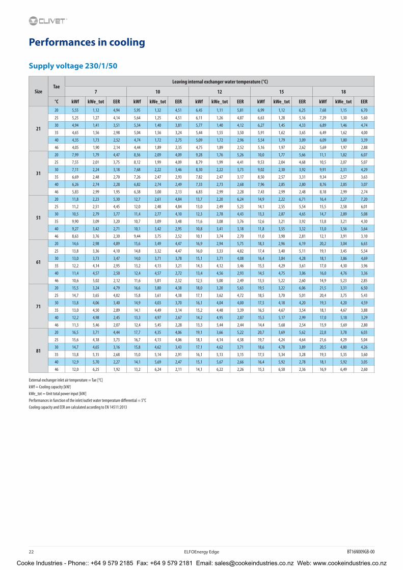
Performances in cooling
Supply voltage 230/1/50
SizeTae
Leaving internal exchanger water temperature (°C)
7 10 12 15 18
°C kWf kWe_tot EER kWf kWe_tot EER kWf kWe_tot EER kWf kWe_tot EER kWf kWe_tot EER
21
20 5,55 1,12 4,94 5,95 1,32 4,51 6,45 1,11 5,81 6,99 1,12 6,25 7,68 1,15 6,70
25 5,25 1,27 4,14 5,64 1,25 4,51 6,11 1,26 4,87 6,63 1,28 5,16 7,29 1,30 5,60
30 4,94 1,41 3,51 5,34 1,40 3,81 5,77 1,40 4,12 6,27 1,45 4,33 6,89 1,46 4,74
35 4,65 1,56 2,98 5,04 1,56 3,24 5,44 1,55 3,50 5,91 1,62 3,65 6,49 1,62 4,00
40 4,35 1,73 2,52 4,74 1,72 2,75 5,09 1,72 2,96 5,54 1,79 3,09 6,09 1,80 3,39
46 4,05 1,90 2,14 4,44 1,89 2,35 4,75 1,89 2,52 5,16 1,97 2,62 5,69 1,97 2,88
31
20 7,99 1,79 4,47 8,56 2,09 4,09 9,28 1,76 5,26 10,0 1,77 5,66 11,1 1,82 6,07
25 7,55 2,01 3,75 8,12 1,99 4,09 8,79 1,99 4,41 9,53 2,04 4,68 10,5 2,07 5,07
30 7,11 2,24 3,18 7,68 2,22 3,46 8,30 2,22 3,73 9,02 2,30 3,92 9,91 2,31 4,29
35 6,69 2,48 2,70 7,26 2,47 2,93 7,82 2,47 3,17 8,50 2,57 3,31 9,34 2,57 3,63
40 6,26 2,74 2,28 6,82 2,74 2,49 7,33 2,73 2,68 7,96 2,85 2,80 8,76 2,85 3,07
46 5,83 2,99 1,95 6,38 3,00 2,13 6,83 2,99 2,28 7,43 2,99 2,48 8,18 2,99 2,74
51
20 11,8 2,23 5,30 12,7 2,61 4,84 13,7 2,20 6,24 14,9 2,22 6,71 16,4 2,27 7,20
25 11,2 2,51 4,45 12,0 2,48 4,84 13,0 2,49 5,23 14,1 2,55 5,54 15,5 2,58 6,01
30 10,5 2,79 3,77 11,4 2,77 4,10 12,3 2,78 4,43 13,3 2,87 4,65 14,7 2,89 5,08
35 9,90 3,09 3,20 10,7 3,09 3,48 11,6 3,08 3,76 12,6 3,21 3,92 13,8 3,21 4,30
40 9,27 3,42 2,71 10,1 3,42 2,95 10,8 3,41 3,18 11,8 3,55 3,32 13,0 3,56 3,64
46 8,63 3,76 2,30 9,44 3,75 2,52 10,1 3,74 2,70 11,0 3,90 2,81 12,1 3,91 3,10
61
20 14,6 2,98 4,89 15,6 3,49 4,47 16,9 2,94 5,75 18,3 2,96 6,19 20,2 3,04 6,63
25 13,8 3,36 4,10 14,8 3,32 4,47 16,0 3,33 4,82 17,4 3,40 5,11 19,1 3,45 5,54
30 13,0 3,73 3,47 14,0 3,71 3,78 15,1 3,71 4,08 16,4 3,84 4,28 18,1 3,86 4,69
35 12,2 4,14 2,95 13,2 4,13 3,21 14,3 4,12 3,46 15,5 4,29 3,61 17,0 4,30 3,96
40 11,4 4,57 2,50 12,4 4,57 2,72 13,4 4,56 2,93 14,5 4,75 3,06 16,0 4,76 3,36
46 10,6 5,02 2,12 11,6 5,01 2,32 12,5 5,00 2,49 13,5 5,22 2,60 14,9 5,23 2,85
71
20 15,5 3,24 4,79 16,6 3,80 4,38 18,0 3,20 5,63 19,5 3,22 6,06 21,5 3,31 6,50
25 14,7 3,65 4,02 15,8 3,61 4,38 17,1 3,62 4,72 18,5 3,70 5,01 20,4 3,75 5,43
30 13,8 4,06 3,40 14,9 4,03 3,70 16,1 4,04 4,00 17,5 4,18 4,20 19,3 4,20 4,59
35 13,0 4,50 2,89 14,1 4,49 3,14 15,2 4,48 3,39 16,5 4,67 3,54 18,1 4,67 3,88
40 12,2 4,98 2,45 13,3 4,97 2,67 14,2 4,95 2,87 15,5 5,17 2,99 17,0 5,18 3,29
46 11,3 5,46 2,07 12,4 5,45 2,28 13,3 5,44 2,44 14,4 5,68 2,54 15,9 5,69 2,80
81
20 16,5 3,71 4,44 17,7 4,35 4,06 19,1 3,66 5,22 20,7 3,69 5,62 22,8 3,78 6,03
25 15,6 4,18 3,73 16,7 4,13 4,06 18,1 4,14 4,38 19,7 4,24 4,64 21,6 4,29 5,04
30 14,7 4,65 3,16 15,8 4,62 3,43 17,1 4,62 3,71 18,6 4,78 3,89 20,5 4,80 4,26
35 13,8 5,15 2,68 15,0 5,14 2,91 16,1 5,13 3,15 17,5 5,34 3,28 19,3 5,35 3,60
40 12,9 5,70 2,27 14,1 5,69 2,47 15,1 5,67 2,66 16,4 5,92 2,78 18,1 5,92 3,05
46 12,0 6,25 1,92 13,2 6,24 2,11 14,1 6,22 2,26 15,3 6,50 2,36 16,9 6,49 2,60
External exchanger inlet air temperature = Tae [°C] kWf = Cooling capacity [kW] kWe_tot = Unit total power input [kW] Performances in function of the inlet/outlet water temperature differential = 5°CCooling capacity and EER are calculated according to EN 14511:2013
Cooke Industries - Phone:: +64 9 579 2185 Fax: +64 9 579 2181 Email: [email protected] Web: www.cookeindustries.co.nz

BT16N009GB-00 ELFOEnergy Edge 23
Performances in heating
Supply voltage 230/1/50
SizeTae
D.B/W.BLeaving internal exchanger water temperature (°C)
30 35 45 55 60
°C kWt kWe_tot COP kWt kWe_tot COP kWt kWe_tot COP kWt kWe_tot COP kWt kWe_tot COP
21
-20/-20,1 1,61 0,83 1,93 1,67 0,93 1,80 - - - - - - - - -
-10/-10,5 2,66 0,94 2,84 2,68 1,03 2,61 2,61 1,25 2,10 - - - - - -
-7/-8 2,98 0,97 3,07 2,99 1,06 2,82 2,90 1,29 2,25 - - - - - -
0/-0,6 3,66 1,04 3,50 3,63 1,13 3,20 3,50 1,38 2,54 3,41 1,63 2,09 3,07 1,53 2,01
2/1,1 3,91 1,06 3,70 3,88 1,14 3,39 3,73 1,39 2,68 3,64 1,66 2,20 3,28 1,55 2,11
7/6 4,96 1,08 4,58 4,91 1,17 4,20 4,72 1,43 3,29 4,61 1,73 2,66 4,15 1,62 2,56
10/8,2 5,27 1,10 4,77 5,22 1,20 4,35 5,03 1,45 3,47 4,89 1,76 2,77 4,40 1,65 2,66
15/13 6,00 1,13 5,32 5,95 1,23 4,82 5,70 1,50 3,81 5,54 1,82 3,04 4,98 1,71 2,92
18/14 6,44 1,18 5,47 6,39 1,29 4,94 6,10 1,52 4,00 5,93 1,86 3,19 5,34 1,74 3,06
31
-20/-20,1 2,29 1,17 1,96 2,38 1,30 1,83 - - - - - - - - -
-10/-10,5 3,79 1,31 2,89 3,82 1,44 2,65 3,72 1,74 2,13 - - - - - -
-7/-8 4,25 1,36 3,13 4,25 1,48 2,87 4,13 1,80 2,30 - - - - - -
0/-0,6 5,21 1,46 3,56 5,17 1,58 3,26 4,98 1,92 2,59 4,85 2,27 2,13 4,36 2,13 2,05
2/1,1 5,56 1,48 3,77 5,52 1,60 3,45 5,32 1,95 2,73 5,18 2,32 2,24 4,66 2,17 2,15
7/6 7,06 1,51 4,67 6,99 1,63 4,28 6,72 2,01 3,35 6,57 2,42 2,71 5,91 2,27 2,60
10/8,2 7,50 1,54 4,86 7,44 1,68 4,43 7,16 2,03 3,53 6,95 2,46 2,82 6,26 2,31 2,71
15/13 8,54 1,58 5,42 8,47 1,73 4,91 8,11 2,09 3,88 7,89 2,55 3,09 7,10 2,39 2,97
18/14 9,17 1,65 5,57 9,09 1,81 5,03 8,68 2,13 4,08 8,44 2,60 3,25 7,60 2,44 3,12
51
-20/-20,1 3,47 1,77 1,96 3,61 1,97 1,83 - - - - - - - - -
-10/-10,5 5,76 1,99 2,89 5,80 2,18 2,65 5,65 2,65 2,13 - - - - - -
-7/-8 6,45 2,06 3,13 6,45 2,25 2,87 6,27 2,73 2,30 - - - - - -
0/-0,6 7,90 2,22 3,56 7,85 2,41 3,26 7,56 2,92 2,59 7,36 3,45 2,13 6,62 3,24 2,05
2/1,1 8,45 2,24 3,77 8,38 2,43 3,45 8,07 2,96 2,73 7,86 3,52 2,24 7,08 3,30 2,15
7/6 10,7 2,30 4,67 10,6 2,48 4,28 10,2 3,04 3,35 9,97 3,68 2,71 8,97 3,45 2,60
10/8,2 11,4 2,34 4,86 11,3 2,55 4,43 10,9 3,08 3,53 10,6 3,74 2,82 9,50 3,51 2,71
15/13 13,0 2,39 5,42 12,9 2,62 4,91 12,3 3,17 3,88 12,0 3,87 3,09 10,8 3,63 2,97
18/14 13,9 2,50 5,57 13,8 2,75 5,03 13,2 3,23 4,08 12,8 3,95 3,25 11,5 3,70 3,12
61
-20/-20,1 4,29 2,25 1,91 4,46 2,50 1,78 - - - - - - - - -
-10/-10,5 7,11 2,53 2,81 7,16 2,77 2,58 6,98 3,36 2,08 - - - - - -
-7/-8 7,96 2,61 3,05 7,97 2,86 2,79 7,74 3,46 2,23 - - - - - -
0/-0,6 9,76 2,82 3,47 9,69 3,05 3,17 9,34 3,71 2,52 9,09 4,38 2,07 8,18 4,11 1,99
2/1,1 10,4 2,84 3,67 10,4 3,08 3,36 9,97 3,75 2,66 9,71 4,46 2,18 8,74 4,18 2,09
7/6 13,2 2,91 4,54 13,1 3,15 4,16 12,6 3,87 3,26 12,3 4,67 2,64 11,1 4,37 2,53
10/8,2 14,1 2,97 4,73 13,9 3,23 4,31 13,4 3,91 3,44 13,0 4,75 2,75 11,7 4,45 2,64
15/13 16,0 3,04 5,27 15,9 3,32 4,78 15,2 4,03 3,77 14,8 4,91 3,01 13,3 4,60 2,89
18/14 17,2 3,17 5,42 17,1 3,48 4,89 16,3 4,11 3,97 15,8 5,01 3,16 14,3 4,70 3,03
71
-20/-20,1 4,80 2,59 1,85 4,99 2,88 1,73 - - - - - - - - -
-10/-10,5 7,96 2,92 2,73 8,01 3,20 2,50 7,81 3,88 2,01 - - - - - -
-7/-8 8,91 3,02 2,95 8,92 3,30 2,71 8,66 4,00 2,17 - - - - - -
0/-0,6 10,9 3,25 3,36 10,8 3,53 3,08 10,5 4,28 2,44 10,17 5,06 2,01 9,16 4,74 1,93
2/1,1 11,7 3,28 3,56 11,6 3,56 3,26 11,2 4,33 2,58 10,9 5,15 2,11 9,78 4,83 2,03
7/6 14,8 3,36 4,40 14,7 3,64 4,04 14,1 4,46 3,16 13,8 5,39 2,56 12,4 5,05 2,46
10/8,2 15,7 3,43 4,58 15,6 3,73 4,18 15,0 4,51 3,33 14,6 5,48 2,66 13,1 5,14 2,56
15/13 17,9 3,51 5,11 17,8 3,84 4,63 17,0 4,65 3,66 16,5 5,67 2,92 14,9 5,32 2,80
18/14 19,2 3,66 5,25 19,1 4,02 4,74 18,2 4,74 3,84 17,7 5,78 3,06 15,9 5,42 2,94
81
-20/-20,1 5,48 3,03 1,81 5,70 3,37 1,69 - - - - - - - - -
-10/-10,5 9,09 3,41 2,67 9,15 3,74 2,45 8,92 4,53 1,97 - - - - - -
-7/-8 10,2 3,52 2,89 10,2 3,85 2,65 9,89 4,67 2,12 - - - - - -
0/-0,6 12,5 3,80 3,29 12,4 4,12 3,01 11,9 5,00 2,39 11,6 5,91 1,97 10,5 5,54 1,89
2/1,1 13,3 3,83 3,48 13,2 4,15 3,19 12,7 5,06 2,52 12,4 6,02 2,06 11,2 5,64 1,98
7/6 16,9 3,93 4,30 16,8 4,25 3,95 16,1 5,21 3,09 15,7 6,29 2,50 14,2 5,90 2,40
10/8,2 18,0 4,01 4,48 17,8 4,36 4,09 17,2 5,27 3,26 16,7 6,40 2,60 15,0 6,00 2,50
15/13 20,5 4,09 5,00 20,3 4,48 4,53 19,4 5,43 3,58 18,9 6,62 2,85 17,0 6,21 2,74
18/14 22,0 4,28 5,14 21,8 4,70 4,64 20,8 5,53 3,76 20,2 6,46 3,13 18,2 6,33 2,88
External exchanger inlet air temperature = Tae [°C] D.B. = Dry bulb W.B. = Wet bulbkWt = Heating capacity [kW] kWe_tot = Unit total power input [kW]
Performances in function of the inlet/outlet water temperature differential = 5°C The data of the heat capacity and COP include defrostingsHeating capacity and COP are calculated according to EN 14511:2013
Cooke Industries - Phone:: +64 9 579 2185 Fax: +64 9 579 2181 Email: [email protected] Web: www.cookeindustries.co.nz

24 ELFOEnergy Edge BT16N009GB-00
Performances in cooling
Supply voltage 400/3/50+N
SizeTae
Leaving internal exchanger water temperature (°C)
7 10 12 15 18
°C kWf kWe_tot EER kWf kWe_tot EER kWf kWe_tot EER kWf kWe_tot EER kWf kWe_tot EER
61
20 14,7 3,05 4,82 15,7 3,57 4,41 17,1 3,01 5,67 18,5 3,03 6,10 20,3 3,11 6,54
25 13,9 3,43 4,05 14,9 3,39 4,41 16,2 3,40 4,75 17,5 3,48 5,04 19,3 3,53 5,47
30 13,1 3,81 3,43 14,1 3,79 3,72 15,3 3,79 4,02 16,6 3,92 4,23 18,2 3,94 4,62
35 12,3 4,23 2,91 13,3 4,22 3,16 14,4 4,21 3,42 15,6 4,38 3,56 17,2 4,39 3,91
40 11,5 4,68 2,46 12,5 4,67 2,69 13,5 4,66 2,89 14,6 4,86 3,02 16,1 4,86 3,31
46 10,7 5,13 2,09 11,7 5,12 2,29 12,6 5,11 2,46 13,7 5,33 2,56 15,0 5,34 2,82
71
20 16,5 3,68 4,47 17,7 4,32 4,09 19,1 3,64 5,26 20,7 3,66 5,66 22,8 3,76 6,07
25 15,6 4,15 3,75 16,7 4,10 4,09 18,1 4,11 4,41 19,7 4,20 4,68 21,6 4,26 5,07
30 14,7 4,61 3,18 15,8 4,58 3,46 17,1 4,59 3,73 18,6 4,74 3,92 20,5 4,77 4,29
35 13,8 5,11 2,70 15,0 5,10 2,93 16,1 5,09 3,17 17,5 5,30 3,31 19,3 5,31 3,63
40 12,9 5,65 2,28 14,1 5,65 2,49 15,1 5,63 2,68 16,4 5,87 2,80 18,1 5,88 3,07
46 12,0 6,21 1,94 13,2 6,19 2,13 14,1 6,18 2,28 15,3 6,45 2,38 16,9 6,46 2,61
81
20 18,3 4,63 3,94 19,6 5,43 3,60 21,2 4,57 4,64 23,0 4,60 4,99 25,3 4,72 5,35
25 17,3 5,22 3,31 18,6 5,15 3,60 20,1 5,17 3,89 21,8 5,29 4,12 24,0 5,36 4,47
30 16,3 5,80 2,80 17,6 5,77 3,05 19,0 5,77 3,29 20,6 5,97 3,46 22,7 6,00 3,78
35 15,3 6,43 2,38 16,6 6,42 2,59 17,9 6,40 2,79 19,4 6,67 2,91 21,4 6,68 3,20
40 14,3 6,66 2,15 15,6 6,64 2,35 16,8 6,68 2,51 18,2 6,87 2,65 20,0 6,79 2,95
46 13,3 6,88 1,94 14,6 6,92 2,11 15,6 6,79 2,30 17,0 6,93 2,45 18,7 6,93 2,70
External exchanger inlet air temperature = Tae [°C] kWf = Cooling capacity [kW] kWe_tot = Unit total power input [kW] Performances in function of the inlet/outlet water temperature differential = 5°CCooling capacity and EER are calculated according to EN 14511:2013
Cooke Industries - Phone:: +64 9 579 2185 Fax: +64 9 579 2181 Email: [email protected] Web: www.cookeindustries.co.nz

BT16N009GB-00 ELFOEnergy Edge 25
Performances in heating
Supply voltage 400/3/50+N
SizeTae
D.B/W.BLeaving internal exchanger water temperature (°C)
30 35 45 55 60
°C kWt kWe_tot COP kWt kWe_tot COP kWt kWe_tot COP kWt kWe_tot COP kWt kWe_tot COP
61
-20/-20,1 4,09 2,15 1,90 4,25 2,39 1,78 - - - - - - - - -
-10/-10,5 6,77 2,42 2,80 6,82 2,65 2,57 6,65 3,21 2,07 - - - - - -
-7/-8 7,58 2,50 3,04 7,59 2,73 2,78 7,37 3,31 2,23 - - - - - -
0/-0,6 9,30 2,69 3,46 9,23 2,92 3,16 8,90 3,54 2,51 8,66 4,19 2,07 7,79 3,93 1,99
2/1,1 9,94 2,72 3,66 9,86 2,94 3,35 9,49 3,58 2,65 9,25 4,26 2,17 8,33 4,00 2,08
7/6 12,6 2,78 4,53 12,5 3,01 4,15 12,0 3,69 3,25 11,7 4,46 2,63 10,6 4,18 2,53
10/8,2 13,4 2,84 4,71 13,3 3,09 4,30 12,8 3,73 3,43 12,4 4,53 2,74 11,2 4,25 2,63
15/13 15,3 2,90 5,26 15,1 3,18 4,76 14,5 3,85 3,76 14,1 4,69 3,00 12,7 4,40 2,88
18/14 16,4 3,03 5,40 16,2 3,33 4,88 15,5 3,92 3,95 15,1 4,79 3,15 13,6 4,49 3,02
71
-20/-20,1 4,80 2,58 1,86 4,99 2,87 1,74 - - - - - - - - -
-10/-10,5 7,96 2,90 2,74 8,01 3,18 2,52 7,81 3,86 2,03 - - - - - -
-7/-8 8,91 3,00 2,97 8,92 3,28 2,72 8,66 3,97 2,18 - - - - - -
0/-0,6 10,9 3,23 3,38 10,8 3,50 3,10 10,5 4,25 2,46 10,2 5,03 2,02 9,16 4,71 1,94
2/1,1 11,7 3,26 3,58 11,6 3,53 3,28 11,2 4,30 2,59 10,9 5,12 2,12 9,78 4,80 2,04
7/6 14,8 3,34 4,43 14,7 3,61 4,06 14,1 4,43 3,18 13,8 5,35 2,57 12,4 5,02 2,47
10/8,2 15,7 3,41 4,61 15,6 3,71 4,21 15,0 4,48 3,35 14,6 5,45 2,68 13,1 5,11 2,57
15/13 17,9 3,48 5,14 17,8 3,81 4,66 17,0 4,62 3,68 16,5 5,63 2,94 14,9 5,28 2,82
18/14 19,2 3,64 5,29 19,1 4,00 4,77 18,2 4,71 3,87 17,7 5,75 3,08 15,9 5,39 2,96
81
-20/-20,1 5,48 3,05 1,80 5,70 3,39 1,68 - - - - - - - - -
-10/-10,5 9,09 3,43 2,65 9,15 3,76 2,43 8,92 4,56 1,96 - - - - - -
-7/-8 10,2 3,55 2,87 10,2 3,88 2,63 9,89 4,70 2,10 - - - - - -
0/-0,6 12,5 3,82 3,27 12,4 4,14 2,99 11,9 5,03 2,37 11,6 5,95 1,95 10,5 5,58 1,88
2/1,1 13,3 3,86 3,46 13,2 4,18 3,16 12,7 5,09 2,50 12,4 6,06 2,05 11,2 5,68 1,97
7/6 16,9 3,95 4,28 16,8 4,27 3,92 16,1 5,24 3,07 15,7 6,33 2,49 14,2 5,93 2,39
10/8,2 18,0 4,03 4,45 17,8 4,39 4,06 17,2 5,30 3,24 16,7 6,44 2,59 15,0 6,04 2,48
15/13 20,5 4,12 4,97 20,3 4,51 4,50 19,4 5,47 3,55 18,9 6,66 2,84 17,0 6,25 2,72
18/14 22,0 4,30 5,10 21,8 4,73 4,61 20,8 5,57 3,73 20,2 6,80 2,98 18,2 6,37 2,86
External exchanger inlet air temperature = Tae [°C] D.B. = Dry bulb W.B. = Wet bulbkWt = Heating capacity [kW] kWe_tot = Unit total power input [kW] Performances in function of the inlet/outlet water temperature differential = 5°C The data of the heat capacity and COP include defrostingsHeating capacity and COP are calculated according to EN 14511:2013
Cooke Industries - Phone:: +64 9 579 2185 Fax: +64 9 579 2181 Email: [email protected] Web: www.cookeindustries.co.nz

26 ELFOEnergy Edge BT16N009GB-00
Accessories separately supplied Every accessory is marked with a configuration code, for instance IBHX.
When the letter X is placed at the end, this means that the accessory is supplied separately. If there is no X in the code, the accessory is mounted in the factory.
IBHX – Back-up electrical heater
The backup electrical heater provide additional heating capacity during extremely cold outdoor temperatures operation conditions. Nominal capacity is 3 kW and it is adjustable.
Back-up heater is designed to be wall mounted in indoor locations only, water piping connections provided by the customer.
Back-up heater requires dedicated power supply: 230/1/50
Dimensions are: 80mm x 220mm x 280mm
Water inlet/outlet connections: G1”
Accessory available only for sizes 21 and 31, built-in solution as standard for the other sizes.
Cooke Industries - Phone:: +64 9 579 2185 Fax: +64 9 579 2181 Email: [email protected] Web: www.cookeindustries.co.nz

BT16N009GB-00 ELFOEnergy Edge 27
Dimensional drawings
ELFOEnergy Edge - Size 21-31
1. Compressor compartment
2. Electrical panel
3. Power input
4. Functional spaces
5. Electric fan (supply - return)
6. Internal exchanger water inlet (OD = 1” GAS)
7. Internal exchanger water outlet (OD = 1” GAS)
8. Support point
9. Drain hole
(M) Air Supply
Size 21 31
Length mm 1210 1210
Depth mm 402 402
Height mm 945 945
Operating weight kg 99 99
Shipping weight kg 117 117
The presence of optional accessories may result in a substantial variation of the weights shown in the table.
DAAPA21_0 REV00Data: 05/12/2016
Cooke Industries - Phone:: +64 9 579 2185 Fax: +64 9 579 2181 Email: [email protected] Web: www.cookeindustries.co.nz

28 ELFOEnergy Edge BT16N009GB-00
Dimensional drawings
ELFOEnergy Edge - Size 51-81
1. Compressor compartment
2. Electrical panel
3. Power input
4. Functional spaces
5. Electric fan (supply - return)
6. Internal exchanger water inlet (OD = 1” 1/4 GAS)
7. Internal exchanger water outlet (OD = 1” 1/4 GAS)
8. Support point
9. Drain hole
(M) Air Supply
Size 51 61 71 81
Length mm 1404 1404 1404 1404
Depth mm 405 405 405 405
Height mm 1414 1414 1414 1414
Operating weight kg 162 162 162 162
Shipping weight kg 183 183 183 183
The presence of optional accessories may result in a substantial variation of the weights shown in the table.
DAAPA51_0 REV00Data: 05/12/2016
Cooke Industries - Phone:: +64 9 579 2185 Fax: +64 9 579 2181 Email: [email protected] Web: www.cookeindustries.co.nz

BT16N009GB-00 ELFOEnergy Edge 29
Page intentionally left blank
Cooke Industries - Phone:: +64 9 579 2185 Fax: +64 9 579 2181 Email: [email protected] Web: www.cookeindustries.co.nz

30 ELFOEnergy Edge BT16N009GB-00
Page intentionally left blank
Cooke Industries - Phone:: +64 9 579 2185 Fax: +64 9 579 2181 Email: [email protected] Web: www.cookeindustries.co.nz

BT16N009GB-00 ELFOEnergy Edge 31
Page intentionally left blank
Cooke Industries - Phone:: +64 9 579 2185 Fax: +64 9 579 2181 Email: [email protected] Web: www.cookeindustries.co.nz

CLIVET SPAVia Camp Lonc 25, Z.I. Villapaiera - 32032 Feltre (BL) - Italy Tel. + 39 0439 3131 - Fax + 39 0439 313300 - [email protected]
CLIVET UK LTD (Sales)4 Kingdom Close, Segensworth East - Fareham, Hampshire - PO15 5TJ - United KingdomTel. + 44 (0) 1489 572238 - Fax + 44 (0) 1489 573033 - [email protected]
CLIVET AIRCON LTD (Service and Maintenance Division)Units F5&F6 Railway Triangle Ind EST, Walton Road - Portsmouth, Hampshire - PO6 1 TG - United KingdomTel. + 44 (0) 2392 381235 - Fax + 44 (0) 2392 381243 - [email protected]
CLIVET ESPAÑA COMERCIAL S.L. (Sales)Calle Gurb, 17 1° 1a - 08500 Vic, Barcelona - EspañaTel. + 34 93 8606248 - Fax + 34 93 8855392 - [email protected]
CLIVET ESPAÑA S.A.U. (Service and Maintenance Division)Calle Real de Burgos n°12 - 28860, Paracuellos del Jarama, Madrid - EspañaTel. + 34 91 6658280 - Fax + 34 91 6657806 - [email protected]
CLIVET GmbHHummelsbütteler Steindamm 84, 22851 Norderstedt - GermanyTel. + 49 (0) 40 32 59 57-0 - Fax + 49 (0) 40 32 59 57-194 - [email protected]
CLIVET RUSSIAElektrozavodskaya st. 24, office 509 - 107023, Moscow, RussiaTel. + 74956462009 - Fax + 74956462009 - [email protected]
CLIVET MIDEAST FZCODubai Silicon Oasis (DSO), High Bay Complex, Ind Unit No. 3 - PO Box 342009 - DUBAI, UAETel. + 97 14 3208499 - Fax + 97 14 3208216 - [email protected]
CLIVET AIRCONDITIONING SYSTEMS PRIVATE LTD 3C3, Gundecha Onclave - Kherani Road, Saki Naka, Andheri (East), Mumbai 400 072 (INDIA)Tel. + 91 - 22 - 6193 7000 - Fax + 91 - 22 - 6193 7001 - [email protected]
w w w . c l i v e t . c o m
Cooke Industries - Phone:: +64 9 579 2185 Fax: +64 9 579 2181 Email: [email protected] Web: www.cookeindustries.co.nz