PES is a pacing technique using an intermittent or continuous introduction of an electrical current to the intracardiac surface through an electrode catheter. Cells near the electrodes depolarize and begin a
wave of depolarization that propagates throughout the heart. This facilitates the evaluation of cardiac refractory
periods, conduction dynamics, automaticity and arrhythmic mechanisms.
Presenter
Presentation Notes
Programmed electrical stimulation (PES) is the timed delivery of pacing stimuli to reproduce a patient’s clinical arrhythmia under controlled conditions. PES is a pacing technique using an intermittent or continuous introduction of an electrical current to the intracardiac surface through an electrode catheter. Cells near the electrodes depolarize and begin a wave of depolarization that propagates throughout the heart. This facilitates the evaluation of cardiac refractory periods, conduction dynamics, automaticity and arrhythmic mechanisms.
3 _
+
+
Unipolar Cathodal
Unipolar Anodal
Bipolar
Unipolar versus Bipolar Pacing Thresholds
Pacing Threshold Strength-Interval curve
_
Presenter
Presentation Notes
Unipolar versus Bipolar pacing Thresholds: In this graph, as the pacing interval is continuously shortened getting closer and closer to the relative refractory period and then finally reaching the effective refractory period, the amount of current necessary to capture the myocardium (pacing threshold) becomes greater and greater as you enter the relative refractory period. It finally can no longer capture once the effective refractory period has been reached. Bipolar (+ and – poles), anodal (+ pole) and cathodal (- pole) pacing will each exhibit a different curve representing the current necessary to capture the myocardium at the different pacing intervals (pacing threshold strength-interval curve). Those different types of thresholds are described below: Unipolar pacing threshold – The unipolar cathodal (negative electrode) pacing threshold is usually lower than the anodal (positive electrode) threshold. Of note, the cathodal relative refractory period is longer than the anodal one. With unipolar pacing, normally the cathode is used for pacing because as stated above it has the lower threshold. Unipolar pacing is useful for assessing scar tissue or the completeness of ablation lines. To do so, you need a constant current pacing device and you pace continuously at 10mA. If the tissue captures, it means the tissue has not been ablated (if assessing a block line for transmural ablation) or that the tissue if viable tissue and not scar. If it fails to pace it means the tissue has been ablated or it is scar (for ischemic VT). Bipolar pacing thresholds – With bipolar pacing, the threshold curve follows the lower values of the unipolar cathodal and anodal curves. Thus as in the diagram the bipolar threshold curve follows the anodal curve for a current between 2-9 mA and the unipolar cathodal curve for a current from 0-2mA. Thus, bipolar pacing will always give the lower threshold. For a bipolar pacing configuration, either the cathode (-) or anode (+) electrode can capture the tissue depending on what the thresholds are and whether or not the anode is in contact with the tissue. Thus, both sites can capture the tissue if the pacing output is above the threshold of the anodal and cathodal electrodes. However, if the pacing output is set between the cathodal and anodal thresholds, then only one (cathode or anode) will capture the tissue. In the example in the diagram a 1mA output at a 360ms delay will capture at the cathode, but not at the anode, because 1mA is higher than the cathodal threshold, but lower than the anodal threshold. Thus, bipolar pacing appears to be the best method, however, as described above for special situations such as evaluating scar or ablation lines, unipolar pacing can be useful.
4
Programmed Electrical Stimulation PES consists of three types of pacing:
PES is used to measure and evaluate …. – Refractory periods – Conduction properties – Pattern of myocardial activation – Tachycardia Characteristics
Initiation Termination Differentiation
Presenter
Presentation Notes
PES consists of three types of pacing: (These will be explained in the next few slides) Incremental (burst) Decremental (ramp) Extrastimulus PES is used to measure and evaluate …. Refractory periods Conduction properties – i.e. is it decremental conduction (the faster you pace the slower the conductions gets) or non-decremental (the faster you pace the conduction speed does not slow), is there normal or abnormal conduction, is there retrograde conduction, are the P wave and QRS complexes normal width (conduction through the normal conduction system) or wide (aberrant conduction – not through the normal conduction system), etc. Pattern of myocardial activation – is it normal (through the normal conduction system and in the correct activation sequence) or abnormal (conduction is through an accessory pathway or conduction is not in the normal activation sequence). Look for the earliest “A” wave and earliest “V” wave. Are they normal? Tachycardia Characteristics Initiation – is it spontaneous (automatic mechanism) or induced by pacing (reentry or triggered activity), does it slowly speed up (automatic) or have a sudden onset (reentry), or is it induced by adenosine (vagally mediated atrial fibrillation), etc. Termination – can it be terminated with pacing (reentry), does it have the fatigue phenomenon – slow down and terminate (automaticity), can it be terminated with adenosine (such as accessory pathways in the antegrade direction during atrioventricular tachycardia, reentrant and triggered atrial tachycardias, and VTs mediated by cyclic-AMP dependent triggered activity due to delayed afterdepolarizations). (Josephson, ME. Clinical Cardiac Electrophysiology: Techniques and Interpretations, 3rd Edition. Lippincott, Williams and Wilkins, Philadelphia, 2002. pp. 311, 405, 560, 562.) Differentiation – there are various pacing maneuvers used to differentiate between the various arrhythmias such as parahisian pacing or pacing during adenosine administration which determine whether the conduction is through the normal conduction system or an accessory pathway. These will be explained later with the arrhythmia section.
5
Definitions and Types of PES
Pacing Drive Train – a series of 6-10 fixed paced stimuli at a constant rate that are separated by a pause. Referred to as “S1s” (stimulus cycle length #1) .
S 1 S 1 S 1 S 1 S 1 S 1 S 1 S 1 S 2Sensed
DRIVETRAIN
S 3 S 4
Presenter
Presentation Notes
A “pacing drive train” consists of 6-10 beats (usually 8 and all are called S1) that are delivered before giving an extrastimulus (S2) beat in order to establish a uniform and consistent refractoriness. In other words it will stabilize the refractory period to a set and consistent duration (length) so that the pacing results with extrastimuli can be very reproducible. If the drive train is not used, the length of the refractory period will vary depending on the autonomic and rate influence. Thus the drive train allows for reliable results. It is sort of telling the heart, “On your mark, get set…”.
6
Incremental Pacing - is pacing the heart at a fixed rate. The rate is increased (pacing interval decreased) with each set of beats.
Definitions and Types of PES
S1-S1 = 400 S1-S1 = 390 S1-S1 = 380 S1-S1 = 370
Presenter
Presentation Notes
PES consists of three types of pacing: incremental (burst), decremental (ramp) and extrastimulus. Incremental pacing (Figure A) is a train of electrical impulses delivered at fixed cycle lengths. The train may last a few beats or several minutes. It can be used to determine refractory periods or initiate or terminate arrhythmias. It can also be used to determine the conduction properties. That is, when the rate is increased does conduction slow (decremental conduction) or speed up or stay the same (non-decremental conduction). This can also be used to measure the wenckebach interval (this will be explained in detail later).
7
Click to start
Sns Sns Sns Sns
TACHY.SENSE
S 1 S 1S 1S 1S 1 SnsSnsSns
RAMP
Decremental Pacing – pacing at a progressively increasing heart rate by decreasing the amount of time between each paced beat. Used primarily to induce or terminate tachycardias. It is also called “ramp” pacing.
Definitions and Types of PES
Presenter
Presentation Notes
Decremental pacing: With decremental pacing each consecutive beat becomes faster and faster. This is often called “ramp” pacing, especially in regard to internal defibrilltors. Each beat in the ramp will be a set number of milliseconds less than the previous impulse, or a percentage of the previous impulse. It can be used to either terminate of induce arrhythmias. Some doctors call it “scan” pacing as well. For example, if an unstable (symptomatic) arrhythmia is occurring and the doctor wants to quickly know at what rate of pacing it can be terminated, he will use this ramp pacing. The arrhythmia will terminate at a specific rate and the doctor can go back and look to see what rate that was. Then when the arrhythmia is later induced again, the doctor will only need to pace at a steady rate at the rate that was determined by the ramp pacing when it terminated the tachycardia. Decremental pacing can also be used to induce arrhythmias. If so the rate is usually only increased up to 300-350 beats per minute (bpm), because rates faster than that may induce ventricular fibrillation or atrial fibrillation. However, if the doctor wishes to induce those arrhythmias he may pace as fast as up to 600 bpm.
8
Exrastimulus Pacing S 1 S 1 S 1 S 1 S 1 S 1 S 1 S 1 S 2 Sensed
DRIVETRAIN
S 1 S 1 S 1 S 1 S 1 S 1 S 1 S 1 S 2 Sensed
DRIVETRAIN
S 3
S 1 S 1 S 1 S 1 S 1 S 1 S 1 S 1 S 2Sensed
DRIVETRAIN
S 3 S 4
Single extras
Double extras
Triple extras
For the standard EP study to test the refractory periods, one extrastimulus (S2) will be used. If a second extrastimulus is used, it is usually for arrhythmia induction and is called “S3”. Up to 3 (S4) extrastimuli (S2, S3, S4) can be given in a standard EPS. Any more than 3 extrastimuli would induce a non-clinical arrhythmia. That is, it could induce an arrhythmia in a normal subject.
Definitions and Types of PES
Presenter
Presentation Notes
In extrastimulus pacing (Figure B), one or more extrastimuli (premature impulses) are delivered at progressively shorter intervals, either during the patient’s sinus rhythm or following an incremental train of 8 to 10 beats. The intrinsic or paced beat is Stimulus 1 (S1). The first extrastimulus is timed from S1 and is labeled S2. Additional extrastimuli, when used, are labeled S3, S4 and so on. To successfully reproduce a patient’s arrhythmia, an EP may vary the timing or number of extrastimuli, adjust the site of stimulation, or do both. Induction attempts are patient-specific and proceed from minimally aggressive to more aggressive.
For triple extrastimuli (S4), the S1-S2 and S2-S3 may be reduced with either the S1-S2 being long and the S2-S3 being short or vice versa. They can also be decreased simultaneously. Some arrhythmias are often easily induced by a short (S1-S2) - long (S2-S3) configuration.
Presenter
Presentation Notes
Common extrastimulus arrhythmia nduction pacing protocol: Basic cycle lengths – The basic cycle lengths (S1-S1) used for inducing both atrial and ventricular arrhythmias are normally 600ms and then 400ms. Single extrastimuli - For atrial arrhythmias, when delivering an S2 (one extrastimuli), the S1-S1 interval will be set first at 600ms and then at 400ms (some doctors may use 500ms) and the S1-S2 will be progressively decreased by 10ms decrements all the way down to the ERP for each of those S1-S1 intervals. However, many doctors prefer not to decrease the S1-S2 to less than 200ms due to the possibility of inducing atrial fibrillation. For ventricular arrhythmias, the S1-S1 used are the same as that for atrial arrhythmias, but the S1-S2 will be decreased from the ERP + 60ms down to the ERP or 200ms. Double extrastimuli - For atrial arrhythmias, when delivering an S3 (2 extrastimuli), the S1-S1 interval will be set first at 600ms and then at 400ms and the S1-S2 will be also be set between 600-200ms or down to the ERP (progressively decreased by 10ms decrements all the way down to the ERP or 200ms for each complete cycle of decreasing the S2-S3 from 600-200ms or down to the ERP by 10ms decrements). The S2-S3 interval will be progressively decreased by 10-20ms each set. For ventricular arrhythmias, the S1-S1 used are the same as that for atrial arrhythmias, but the S1-S2 and S2-S3 will be decreased from the ERP + 60ms down to the ERP or 200ms. Triple extrastimuli – For atrial arrhythmias, when delivering an S4 (3 extrastimuli) the S1-S1 interval will be set first at 600ms and then at 400ms and the S1-S2 and S2-S3 intervals will be also be set between 600-200ms or down to the ERP (progressively decreasing them either together or separately by 10ms decrements all the way down to the ERP or 200ms for each complete set of decreasing the S3-S4 from 600-200ms or down to the ERP by 10ms decrements). The S3-S4 interval will be progressively decreased by 10-20ms each set. For ventricular arrhythmias, the S1-S1 used are the same as that for atrial arrhythmias, but the S1-S2, S2-S3 and S3-S4 will be decreased from the ERP + 60ms down to the ERP or 200ms. When inducing paroxysmal supraventricular tachycardia, usually basic cycle lengths of 600ms and 400 ms are used. When there is the possibility of inducing atrial fibrillation (AF), the minimum S1-S2 and S2-S3 used are 200 ms, because you do not want to induce AF during induction of PSVT (AVNRT or AVRT). When inducing VT, usually basic cycle lengths of 600ms and 400 ms are used. The minimum S1-S2, S2-S3, and S3-S4 are the ERP. However, many facilities may use down to 200 ms in patients with asymptomatic Brugada syndrome, because there has been no definite conclusion about the induction protocol in patients with asymptomatic Brugada patients. For VT induction (other than for asymptomatic Brugada), the ventricular extrastimuli often used are as follows: S1-S1: 600 ms or 400 ms; S1-S2: from 60ms longer than the ERP down to the ERP (ex. If the ERP is 210ms, then thy start the S1-S2 interval at 270ms and keep going down by 10ms increments to the ventricular ERP.); S2-S3: from 60ms longer than the ERP down to the ERP; S3-S4: from 60ms longer than the ERP down to the ERP. Also many facilities also use short-long short stimuli to induce bundle branch reentrant tachycardias (ex. S1-S1 = 400 ms, S1-S2 = 600 ms; S2-S3= 400-200). This often renders arrhythmias such as bundle branch reentrant tachycardias more easy to induce. For VT induction coupling intervals less than 180ms should be avoided or else polymorphic VT or VF may be induced. However, if the patient had a cardiac arrest, then they may wish to induce polymorphic VT and thus use less than 180ms. If a cycle length of greater than or equal to 240ms can induce a monomorphic VT, then that means that the induction of spontaneous VT or recurrence is likely. (Josephson, ME. Clinical Cardiac Electrophysiology: Techniques and Interpretations, 3rd Edition. Lippincott, Williams and Wilkins, Philadelphia, 2002. pp. 446-447) Drive cycle lengths of 600ms and 400ms before the extrastimuli are typically used when inducing arrhythmias especially VT. However some doctors use other cycle lengths such as 500ms, but it is not always as successful. It is best to use the cycle length that will allow the use of the least number of extrastimuli to induce the arrhythmia, because the more extrastimuli you use the greater the chance of inducing a non-clinical arrhythmia. The amount of current used can also help induce arrhythmias, but in general no more than 5 mA should be used, because greater than that can induce VF, and thus, is not recommended. It works by shortening the local refractoriness. Also pulse widths greater than 2ms are associated with a greater incidence of polymorphic VT or VF, and thus should not be used. Thus a pulse width between 1-2ms at twice the diastolic threshold is of standard use. (Josephson, ME. Clinical Cardiac Electrophysiology: Techniques and Interpretations, 3rd Edition. Lippincott, Williams and Wilkins, Philadelphia, 2002. pp. 452.)
10
Pacing Protocols in EPS Typical Pacing Protocols
– Right Atrial Straight (Incremental) Pacing – Decremental Atrial Pacing – Programmed Atrial Stimuli with Atrial
Extrastimuli – Right Ventricular Straight (Incremental)
Pacing – Decremental Ventricular Pacing – Programmed Ventricular Pacing with Single,
Double and Triple Extrastimuli
Presenter
Presentation Notes
Typical pacing protocol in an EPS; Right Atrial Straight Pacing (incremental atrial pacing) – mimics sinus node conduction and is used to determine the basic electrophysiology measurements and atrial, AV node and His-Purkinje conduction properties. It is also used to determine the refractory periods of the AV node, His-Purkinje system and atrium as well as the Wenckebach cycle length of the AV node. Decremental Atrial Pacing – this is rarely used in EPS and is normally only used to terminate atrial tachycardias. Programmed Atrial Stimuli with Atrial Extrastimuli – this is used to determine the basic electrophysiology measurements and the atrial, AV node and His-Purkinje conduction properties, and to determine the refractory periods of the AV node, His-Purkinje system and atrium. Right Ventricular Straight Pacing (incremental ventricular pacing) – this is used to determine the basic electrophysiology measurements and the ventricular and retrograde AV node (ventriculoatrial) conduction properties. It is also used to determine the retrograde refractory periods of the AV node and ventricle, as well as the retrograde Wenckebach cycle length of the AV node. Decremental Ventricular Pacing - this is rarely used in EPS and is normally only used to terminate ventricular tachycardias. Programmed Ventricular Pacing with Single, Double and Triple Extrastimuli - this is used to determine the basic electrophysiology measurements, ventricular and retrograde AV node conduction properties, and retrograde refractory periods of the AV node and ventricle.
11
Refractory Periods General Overview
12
Absolute and Relative Refractory Periods
Absolute (Effective) refractory period - no matter how strong the stimulus is, the cell can not depolarize. Relative refractory period - if the stimulus is strong enough (PAC, PVC or high pacing output) the cell may depolarize
Presenter
Presentation Notes
After a cell becomes depolarized, there is a period of time in which it cannot be depolarized again. That is called the refractory period. There are two types of refractory periods: Absolute refractory period (more commonly called the effective refractory period) – interval after the cell becomes activated that no matter how strong the stimulus, it cannot depolarize Relative refractory period – interval following the absolute refractory period in which although normally it would not be able to be depolarized, if the stimulus is strong enough like a PAC, PVC or high pacing output stimulus, the cell may depolarize
13
Absolute and Relative Refractory Periods
The ventricular relative refractory period (RRP) falls around the middle of the “T wave”, and this is called the vulnerable period. The same occurs for the atrium. If a stimulus or PVC in the ventricle or PAC in the atrium falls in this period, it may induce either atrial fibrillation (if in the atrial RRP), or ventricular tachycardia or ventricular fibrillation (if in the ventricular RRP).
Presenter
Presentation Notes
The ventricular relative refractory period (RRP) falls around the middle of the “T wave”, and this is called the vulnerable period. The same occurs for the atrium. If a stimulus or premature ventricular contraction (PVC) in the ventricle or a PAC in the atrium falls in this period, it may induce either ventricular tachycardia or ventricular fibrillation (if in the ventricular RRP) or atrial fibrillation (if in the atrial RRP). Thus, in the clinical setting this situation should be avoided. Knowing this you can see that if a patient is given drugs, such as Quinidine, which prolong the QT interval, it will extend that vulnerable period out so that even a fairly slow PVC may fall on the “T wave” and induce ventricular tachycardia or ventricular fibrillation. When a PVC does fall on the “T wave”, it is called “R on T”. The same situation can happen with a pacemaker when the pacing stimulus hits the T wave, and in that situation it is called “spike on T”. Both situations need to be avoided.
14
Premature impulses are used to measure refractory periods of cardiac tissue. They are the: • Effective refractory period (ERP) – Phase 2 - longest coupling interval that a premature impulse fails to propagate through cardiac tissue = absolute refractory period
• Cardiac cells cannot be depolarized during the ERP • Coupling interval – time between the last paced impulse and premature impulse.
• Relative refractory period (RRP) – time from the end of the ERP to the beginning of Phase 4 (Phases 3 & 4) – longest coupling interval that a premature impulse results in slow conduction. Time when cells can be depolarized again with a strong enough stimulus.
• If a cardiac cell is stimulated during the RRP, the resulting action potential has a slower Phase 0 slope and the impulse propagates at a slower conduction velocity.
• Functional refractory period (FRP) – shortest time between 2 successive conducted impulses (time when cells can be depolarized again - usually used to describe AV node function). The shortest output of any given input.
Refractory Periods
Presenter
Presentation Notes
In an EP study, The refractory periods are measured by pacing maneuvers. This is done by pacing with runs of several beats at progressively faster rates or by inserting premature impulses (paced beats at a progressively faster rate than the intrinsic rhythm and are called S2) following several beats at a set rate (called S1). The refractory periods of the atrium, AV node and ventricle will al be determined. The EP-defined refractory periods are as follows: The effective refractory period (ERP) is the longest coupling interval for which a premature impulse fails to propagate through cardiac tissue. The ERP corresponds most closely to the absolute refractory period, therefore a cardiac cell absolutely cannot be depolarized during the ERP. The coupling interval is the time between the last paced impulse and the premature impulse. The relative refractory period (RRP) is the time from the end of the ERP to the beginning of Phase 4. It is the longest coupling interval for which a premature impulse results in slow conduction. If a cardiac cell is stimulated during the RRP, the resulting action potential has a slower Phase 0 slope and therefore the impulse propagates at a slower conduction velocity. At the end of the RRP, cardiac tissue is fully recovered. The functional refractory period (FRP) is the shortest time (narrowest interval) between two successive conducted impulses. It is a measurement of both refractoriness and conduction velocity. It usually refers to AV node function.
15
AV Nodal Conduction Curves
16
AV Node Conduction (Refractory) Curves
There are 2 main plots used to show the conduction properties obtained during programmed stimulation: – A1-A2 versus H1-H2 and V1-V2. This gives an assessment of the FRP of the AV
conduction system. – A1-A2 versus A2-H2 and H2-V2 . Allows to actually determine conduction times through
the AV conduction system.
Josephson, ME. Clinical Cardiac Electrophysiology, Techniques and Interpretations (3rd Edition), Lippincott, Williams and Wilkins, 2002, pp.47.
Presenter
Presentation Notes
AV Node Conduction (Refractory) Curves: There are 2 main plots used to show the conduction properties obtained during programmed stimulation: A1-A2 versus H1-H2 and V1-V2. This gives an assessment of the FRP of the AV conduction system. This tells you the functional input-output relationship. In other words, it tells you for what rate you put in, what rate you will get out. It also tells you how fast a rate (A-A or V-V) can feasibly be produced by the tissue being tested. This allows the doctor to decide how dangerous an arrhythmia might be. For example if the shortest V1-V1 is less than 300ms, than it is not as high risk for sudden death as if it had been less than 300ms. Thus, the doctor can determine whether or not an aggressive treatment is needed. A1-A2 versus A2-H2 and H2-V2 . Allows to actually determine conduction times through the AV conduction system.
17
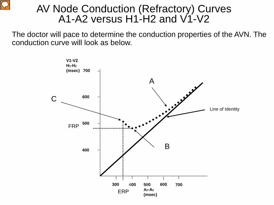
The doctor will pace to determine the conduction properties of the AVN. The conduction curve will look as below.
V1-V2 H1-H2
(msec) 700
AV Node Conduction (Refractory) Curves A1-A2 versus H1-H2 and V1-V2
ERP
FRP
500 A1-A2
(msec)
600
500
600
700 400 300
400
Line of Identity
A
B
C
Presenter
Presentation Notes
A1-A2 versus H1-H2 and V1-V2 Conduction Curve: As the pacing cycle length gets shorter and shorter (i.e., A1-A2 gets shorter), at first the V1-V2 interval will shorten proportionally to the A1-A2 interval following the line of identity. However, at a certain point (point A) when you reach the relative refractory period, although the impulse will still conduct to the ventricle, there is a slowing of the conduction and it begins to leave the line of identity (this would be noted as a slight prolongation of the AH interval). As the atrial rate (A1-A2) gets faster and faster, eventually the conduction in the AV node has slowed so greatly that one beat out of every few beats gets dropped. This is called “Wenckebach” and it it can be seen to occur at point B. You will see an “A”, “H” and “V” and suddenly just an “A” and no “H” and “V”. Thus the V1-V2 interval drastically prolongs due to the dropped beats. You can see in the diagram that from point “B” to point “C” it continues to display Wenckebach. This period is called the “Wenckebach window’. You will also note that point “B” is the shortest V1-V2 interval that can be achieved, because as soon as Wenckebach occurs the V1-V2 interval begins to prolong. Thus point “B” which is the shortest possible V1-V2 is the functional refractory period (FRP) of the atrioventricular node (AVNFRP), because the AVNFRP is the shortest H1-H2 (or V1 - V2) in response to any S1- S2 (A1-A2). Thus, this is the fastest ventricular response you can have to any atrial stimulus. As the atrial rate continues to increase, eventually you hit a point (point C), where nothing can conduct through the AV node and all the “V” waves drop. This is the effective refractory period. This is all normal conduction.
18
Responses to Atrial Extrastimuli There are 3 main patterns of the response to atrial
stimuli: – Type I – Most common and involves the impulse
propagation meeting a progressively greater delay in the AV node without any change in the infranodal (His-Purkinje) conduction. Thus, the AH interval prolongs, but the HV interval does not. Block will occur in the AV node or the atrium.
– Type II – Delay is initially noted in the AV node, but at shorter coupling intervals (S1-S2), delay is noted in the His-Purkinje system. However, block still usually occurs in the AV node first, but may occur in the atrium or occasionally in the His-Purkinje system.
– Type III – Least common and initially conduction slows in the AV node, but at a critical S1-S2, a sudden and marked prolongation occurs in the HV interval (His-Purkinje system). Block first occurs in the His-Purkinje system.
Josephson, ME. Clinical Cardiac Electrophysiology, Techniques and Interpretations (3rd Edition), Lippincott, Williams and Wilkins, 2002, pp.46-47.
Presenter
Presentation Notes
Responses to Atrial Extrastimuli: There are 3 main patterns of response to atrial stimuli: Type I – Most common and involves the impulse propagation meeting progressively greater delay in the AV node without any change in the infranodal (His-Purkinje) conduction. Thus, the AH interval prolongs, but the HV interval does not. Block will occur in the AV node or the atrium. Type II – Delay is initially noted in the AV node, but at shorter coupling intervals (S1-S2), delay is noted in the His-Purkinje system. However, block still usually occurs in the AV node first, but may occur in the atrium or occasionally in the His-Purkinje system. Type III – Least common and initially conduction slows in the AV node, but at a critical S1-S2, a sudden and marked prolongation occurs in the HV interval (His-Purkinje system). Block first occurs in the His-Purkinje system. Thus it is not abnormal to have block in the His-Purkinje system before the AV node. For it to occur, all that is needed is for the FRP of the AV node to be shorter than the RRP of the His-Purkinje system. This can occur in as high as 15%-60% of patients.
19
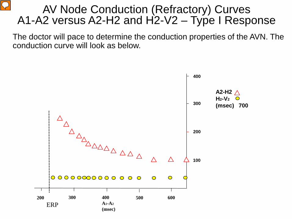
The doctor will pace to determine the conduction properties of the AVN. The conduction curve will look as below.
A2-H2 H2-V2
(msec) 700
AV Node Conduction (Refractory) Curves A1-A2 versus A2-H2 and H2-V2 – Type I Response
ERP 400 A1-A2
(msec)
500
200
300
600 300 200
100
400
Presenter
Presentation Notes
A1-A2 versus A2-H2 and H2-V2 Conduction Curve Response Type I: As the pacing cycle length gets shorter and shorter (i.e., A1-A2 gets shorter), the A2H2 interval prolongs. That means conduction is slowing in the AV node as you enter the relative refractory period. Eventually you will end up hitting the effective refractory period (ERP) and there will be an “A wave” (atrial signal), but no “H” (His potential). That means conduction blocked in the AV node. Also as the pacing cycle length gets shorter and shorter (i.e., A1-A2 gets shorter), the H2V2 does not prolong and stays the same length. In a Type I Response block will occur in the AV node before it does in the His-Purkinje system. (Josephson, ME. Clinical Cardiac Electrophysiology, Techniques and Interpretations (3rd Edition), Lippincott, Williams and Wilkins, 2002, pp.47.)
20
The doctor will pace to determine the conduction properties of the AVN. The conduction curve will look as below.
A2-H2 H2-V2
(msec) 700
AV Node Conduction (Refractory) Curves A1-A2 versus A2-H2 and H2-V2 – Type II Response
ERP 400 A1-A2
(msec)
500
200
300
600 300 200
100
400
Presenter
Presentation Notes
A1-A2 versus A2-H2 and H2-V2 Conduction Curve – Response Type II: As the pacing cycle length gets shorter and shorter (i.e., A1-A2 gets shorter), the A2H2 interval prolongs but not too a great degree. At longer cycle lengths the A2H2 and H2V2 responses are similar to the Response Type I. However, at A1-A2 shorter intervals, the H2V2 begins to start prolonging meaning the relative refractory period of the His-Purkinje system has been reached. In a Type II Response block may occur in either the AV node or His-Purkinje system. It may even hit the effective refractory period of the atrium first. (Josephson, ME. Clinical Cardiac Electrophysiology, Techniques and Interpretations (3rd Edition), Lippincott, Williams and Wilkins, 2002, pp.47-48.)
21
The doctor will pace to determine the conduction properties of the AVN. The conduction curve will look as below.
A2-H2 H2-V2
(msec) 700
AV Node Conduction (Refractory) Curves A1-A2 versus A2-H2 and H2-V2 – Type III Response
ERP 400 A1-A2
(msec)
500
200
300
600 300 200
100
400
Presenter
Presentation Notes
A1-A2 versus A2-H2 and H2-V2 Conduction Curve Response Type III: At longer A1-A2 intervals the curves stay unchanged. At slightly longer intervals there is a gradual slowing of the AV nodal conduction (A2H2), but suddenly at shorter and shorter A1-A2 intervals the H2V2 interval suddenly prolongs. There is a sudden jump in the H2V2 interval. In a Type III Response block will occur in the AV node or His-Purkinje system. The functional refractory period of the His-Purkinje system occurs right before the jump in the H2V2 interval.. (Josephson, ME. Clinical Cardiac Electrophysiology, Techniques and Interpretations (3rd Edition), Lippincott, Williams and Wilkins, 2002, pp.48-49.)
22 22
Types of Conduction Properties
Decremental Conduction – Normal nodal tissue exhibits decremental conduction. – A propagated impulse at a progressively decreasing interval causes a progressive increase in the impulse conduction delay.
(i.e. The increasing prematurity of the impulse = Slower impulse conduction)
Non-Decremental Conduction – Atrial and ventricular myocardium and most accessory pathways (Kent) exhibit non-decremental conduction. – There is no delay in the propagation of an impulse through the tissue despite an increasing prematurity of an impulse.
(i.e All or none conduction)
Presenter
Presentation Notes
Types of Conduction Properties: Decremental Conduction Normal AV nodal tissue exhibits decremental conduction. A propagated impulse at a progressively decreasing interval causes a progressive increase in the impulse conduction delay. (i.e. The increasing prematurity of the impulse = Slower impulse conduction) Non-Decremental Conduction Atrial and ventricular myocardium and most accessory pathways (Kent) exhibit non-decremental conduction. There is no delay in the propagation of an impulse through the tissue despite an increasing prematurity of an impulse. (i.e All or none conduction)
23
S1-S2
AH interval prolongs
With the AV decremental properties, as the pacing rate is increased, eventually the rate of conduction will progressively slow, as seen by progressively longer and longer AH intervals as the S1-S2 or S1-S1 pacing interval is increased. This prolongation indicates the pacing has entered the relative refractory period.
Conduction Properties – AV Decremental Conduction
Presenter
Presentation Notes
Decremental conduction: With the AV decremental properties, as the pacing rate is increased, eventually the rate of conduction will progressively slow, as seen by progressively longer and longer AH intervals as the S1-S2 or S1-S1 pacing interval is increased. This prolongation indicates the pacing has entered the relative refractory period.
24
During incremental pacing Wenckebach occurs due to progressively entering the relative refractory period (RRP) until a beat drops. The ERP also prolongs as each stimulus enters deeper into the RRP.
AV Node Conduction Curve – AV Wenckebach
S1 S1 S1 S1 S1
Dropped beat No “H” and “V”
Phase 0
Presenter
Presentation Notes
AV Wenckebach: This slide shows the mechanism of why AV Wenckebach occurs. During continuous incremental pacing once a critical S1-S1 pacing interval is reached, the successive pacing impulses will fall deeper and deeper into the relative refractory period (RRP) until finally one impulse will fall into the effective refractory period (ERP). In this example the second S1 pacing spike falls just into the RRP, and thus, there is only slight prolongation of the AH interval. Note that the resultant action potential has a slower (less steep) phase 0 (depolarization) and thus the duration of the action potential is prolonged making the third S1 now fall even deeper into the RRP. Therefore, for the third S1 the AH interval is prolonged even further, and the resultant action potential has even and even slower Phase 0 and more prolonged action potential duration. Now when the 4th S1 hits, it lands on the ERP of the action potential from the 3rd S1. Thus, one beat is dropped. Since the 5th S1 lands after the 3rd S1 action potential has ended, it can conduct normally and the cycle is repeated.
25
AV Wenckebach is associated with: Group beating Progressively prolonging AH intervals
AV Node Conduction Curve – AV Wenckebach
Grouped beats Prolonging AH
intervals Dropped beats
Presenter
Presentation Notes
AV Wenckebach is associated with: Group beating - Please note that grouped beating occurs as shown by the encircled beats with the dropped beat between. It will continuously repeat this cycle as long as the pacing at that rate continues. . Progressively prolonging AH intervals - Also you can see that the AH interval progressively prolongs until one beat is dropped.
26
With Wenckebach there are grouped beats with gradual prolongation of the AH interval until conduction to the ventricle eventually drops. Therefore only an occasional “A” wave will not conduct to produce a “V” (see the dropped “V” above). This occurs as pacing is hitting far into the relative refractory period.
AH Intervals
Dropped beat
AV Node Conduction Curve – AV Wenckebach
Presenter
Presentation Notes
AV Wenckebach: This slide shows an actual intra-cardiac ECG strip showing AV Wenckebach. Note again the grouped beating, progressive AH interval prolongation and dropped beat.
27 27
Drugs Used in EP Studies
Presenter
Presentation Notes
The two main drugs from this list used in EP studies are adenosine and isoproterenol. Adenosine is used to discriminate between atrial and ventricular tachycardias and to determine whether conduction is occurring retrograde through the normal conduction system or an accessory pathway. Thus, it can be used to differentiate between an atrioventricular reentrant tachycardia (AVRT; e.g. WPW) or atrioventricular nodal reentrant tachycardia (AVNRT). It is also used to better evaluate accessory pathways (APs), produce AV block so you can better evaluate the atrial signals, and terminate some SVTs. Atrial versus ventricular arrhythmias: If there is a wide QRS tachycardia and you give adenosine, if the tachycardia terminates, you know it was atrial not ventricular and vice versa. AVRT versus AVNRT: If you give adenosine during RV pacing, it will blcok the AV node conduction. Thus, if there are no APs present, you will get no retrograde atrial signal. However, if you do get an atrial signal, that will mean there is an AP present. The affects are short lived lasting only 6-10 seconds. Evaluating APs: Because AV conduction blocks with adenosine, it allows all the activation to proceed antegrade down only the AP and not the normal AV conduction system. Thus, a large delta wave (pre-excitation) will be observed. When you have an arrhythmia like atrial flutter with fast P waves, by blocking the AV nodal conduction with adenosine, there will be only a ventricular escape rhythm and thus, it will be easier to see the P waves. Isoproterenol is used to help induce arrhythmias because it increases the heart rate, automaticity and contractility. It also speeds up the SA nodal and atrial tissue conduction.
28
Autonomic Nervous System
Increases in sympathetic tone increases conduction velocity and decreases refractory periods. Increases in parasympathetic tone decreases
conduction velocity and increases refractory periods.
Presenter
Presentation Notes
Autonomic Nervous System Influence: Increases in sympathetic tone increase the conduction velocity and decrease the refractory periods. Increases in parasympathetic tone decrease the conduction velocity and increase the refractory periods.
29
Determining Refractory Periods in an EPS
30
Relative Refractory Period
The relative refractory period (RRP) is the period of time when only a stimulus greater than normal results in an action potential. The RRP is the longest S1-S2 coupling interval (premature impulse) that causes prolonged conduction of the S2 relative to the basic cycle length (S1-S1). The start of the RRP is just after the end of the full recovery period where the conduction of the S2 and S1 is the same (i.e. the RRP will have slower conduction for S2 than for S1).
Presenter
Presentation Notes
The relative refractory period (RRP) is the period of time when only a stimulus greater than normal results in an action potential. This a strong stimulus like a PAC, PVC or pacing stimulus can make this occur. The RRP is the longest S1-S2 coupling interval (premature impulse) that causes prolonged conduction of the S2 relative to the basic cycle length (S1-S1). The start of the RRP is just after the end of the full recovery period where the conduction of the S2 and S1 is the same (i.e. the RRP will have slower conduction for S2 than for S1).
Relative, (phase 3,4) (RRP). • Time when cells can be depolarized again with a strong enough
stimulus. The longest premature coupling interval at which delay in conduction (prolongation of conduction) occurs.
Refractory Periods: RRP
Presenter
Presentation Notes
Relative, (phase 3,4) (RRP): Time when cells can be depolarized again with a strong enough stimulus. The longest premature coupling interval at which delay in conduction (prolongation of conduction) occurs.
33
Relative Refractory Periods
If a stimulus falls in the relative refractory period, and if it is strong enough the cell will depolarize. However, depolarization (slope of phase 0) will become slower and slower the closer you approach the ERP. For the AV node this is expressed as a progressively lengthening AH interval as you pace closer and closer to the ERP.
Presenter
Presentation Notes
If a stimulus falls in the relative refractory period, and if it is strong enough the cell will depolarize. However, depolarization (slope of phase 0) will become slower and slower the closer you approach the ERP. For the AV node this is expressed as a progressively lengthening AH interval as you pace closer and closer to the ERP.
34
Determination of the Relative Refractory Period
35
Antegrade Relative Refractory Periods: Atrial RRP or ARRP: • The longest S1 - S2 interval at which the S2-A2 interval
exceeds the S1-A1. This is called latency. (-ms) Atrioventricular Nodal RRP or AVNRRP: • The longest A1 - A2 at which the A2-H2 interval exceeds the
A1-H1. (-ms) His Purkinje System RRP or HPRRP: • The longest H1 - H2 at which the H2-V2 interval exceeds the
H1-V1 or results in an aberrant QRS complex. (-ms)
Josephson, ME. Clinical Cardiac Electrophysiology, Techniques and Interpretations (3rd Edition), Lippincott, Williams and Wilkins, 2002, pp.39.
Relative Refractory Period: Antegrade
Presenter
Presentation Notes
Atrial RRP or ARRP: The longest S1 - S2 interval at which the S2-A2 interval exceeds the S1-A1. This is called latency. (-ms) Atrioventricular Nodal RRP or AVNRRP: The longest A1 - A2 at which the A2-H2 interval exceeds the A1-H1. (-ms) His Purkinje System RRP or HPRRP: The longest H1 - H2 at which the H2-V2 interval exceeds the H1-V1 or results in an aberrant QRS complex. (-ms)
Atrial relative refractory period (ARRP): When the S1-S2 interval is 310ms the S2 stimulus produces an atrial depolarization (A wave) followed by a His potential (H) and V wave. Note that the S1-A1 interval is equal to the S2-A2 interval (5ms). As S1-S2 is progressively decreased next to 290ms, the S2 still results in an A wave, followed by an H and V wave showing that the AV node conduction is still intact. However, you will notice now that the S2-A2 interval is longer (10ms) than the S1-A1 interval. This is atrial latency which means the S2 stimulus has fallen into the ARRP. When the S1-S2 interval is further decreased to 270ms, it still results in an A wave, His potential and V wave, but now the S2-A2 is even longer (15ms) meaning the S2 stimulus fell even further into the ARRP. Since 20ms decrements were used for the S1-S2 extrastimulation method, the doctor may go back and use 10ms decrements starting at about 300ms, to obtain a more precise measurement of the RRP.
37
Latency (ARRP)
Latency is defined as the time difference (delay) between the initiation of a stimulus and the observed response to that stimulus. As an extra stimulus is introduced with shorter coupling intervals, the ability of the targeted tissue to accept and conduct this impulse becomes more compromised. Increasing the rate of pacing results in less time for recovery of tissue (shortening of the action potential). This is especially true of AV nodal cells.
Presenter
Presentation Notes
Latency is defined as the time difference (delay) between the initiation of a stimulus and the observed response to that stimulus. As an extra stimulus is introduced with shorter coupling intervals, the ability of the targeted tissue to accept and conduct this impulse becomes more compromised. Increasing the rate of pacing results in less time for recovery of tissue (shortening of the action potential). This is especially true of AV nodal cells.
38
HIS 3-4
Latency con’t.
S1-A1 S1-A1 S2-A2
Presenter
Presentation Notes
Latency: Latency occurs during the ARRP or VRRP and is the delay from the S2 spike to the actual onset of the A wave (atrial pacing) or V wave (ventricular pacing). Thus this example is very similar to the slide on the ARRP. You can see that the S1-A1 interval is short, but the S2-A2 interval is much longer. This is atrial latency which means the S2 stimulus has fallen into the ARRP. This is a normal phenomenon.
39
Retrograde Relative Refractory Periods: Ventriculoatrial RRP or VARRP: • The longest S1 - S2 interval at which the S2-A2 interval
exceeds the S1-A1. (-ms) Ventricular RRP or VRRP: • The longest S1 - S2 interval at which the S2-V2 interval
exceeds the S1-V1. This is called latency. (-ms)
Josephson, ME. Clinical Cardiac Electrophysiology, Techniques and Interpretations (3rd Edition), Lippincott, Williams and Wilkins, 2002, pp.39.
Relative Refractory Period: Retrograde
Presenter
Presentation Notes
Ventriculoatrial RRP or VARRP: The longest S1 - S2 interval at which the S2-A2 interval exceeds the S1-A1. (-ms) Ventricular RRP or VRRP: The longest S1 - S2 interval at which the S2-V2 interval exceeds the S1-V1. This is called latency. The V is measured from the surface ECG or a local electrogram at the site of ventricular pacing (i.e. from the RVA catheter) (-ms)
Ventriculoatrial relative refractory period (VARRP): When the S1-S2 interval is 290ms the S2 stimulus produces a ventricular depolarization (V wave) followed by a His potential (H) and A wave. Note that the H1-A1 interval (60ms) is the same as the H2-A2 interval (60ms), suggesting that the VARRP has not yet been reached. If it had entered the VARRP, H2-A2 would be longer than H1-A1. As it is progressively decreased next to 270ms, the S2 still results in an V wave, followed by an H and A wave showing that the AV node conduction is still intact. However, you will notice now that the H2-A2 interval is longer (H2-A2=90ms) than that observed with an S1-S2 of 290ms (H2-A2=60ms). This is occurring because the impulse falls in the RRP of the AV node (VARRP). When the S1-S2 interval is further decreased to 250ms, now the conduction falls deeper into the VARRP and the H2-A2 now increases to 140ms. Thus the VARRP was 270ms in this example. As you go deeper and deeper into the VRRP, ventriculoatrial wenckebach will occur. Since 20ms decrements were used for the S1-S2 extrastimulation method, the doctor may go back and use 10ms decrements starting at about 300ms, to obtain a more precise measurement of the VARRP.
41
Determination of the Functional Refractory Period
42
Functional Refractory Period (FRP)
The minimum interval between two consecutively conducted impulses through the cardiac tissue.
The FRP of the AV node can vary, but it tends to decrease with decreasing cycle lengths.
For atrial and ventricular tissue it tells you how fast that tissue can conduct on a beat to beat basis.
Presenter
Presentation Notes
Functional Refractory Period: The minimum interval between two consecutively conducted impulses through the cardiac tissue. The FRP of the AV node can vary, but it tends to decrease with decreasing cycle lengths. For atrial and ventricular tissue it tells you how fast that tissue can conduct on a beat to beat basis. There are two pacing techniques to measure the FRP of tissue. They are: Multiple consecutive extrastimuli (usually 3) Incremental pacing at rapid rates
43
Functional Refractory Period
FRP
S1 S2
Presenter
Presentation Notes
Functional Refractory Period (FRP): The FRP tends to fall into the early part of the relative refractory period (RRP). The effective refractory period (ERP) and RRP are related to the duration of the action potential, but the FRP depends more on the refractoriness and conduction velocity of the tissue. It is a measure of the output of a tissue. A good example is with atrial fibrillation (AF). During AF the shortest beat to beat interval is the FRP. Thus, the R to R interval tells the FRP of the AV node and the shortest A to A tells the FRP of the atrium.
44
Functional Refractory Period: Antegrade
Antegrade Functional Refractory Periods: Atrial FRP or AFRP The shortest A1 - A2 in response to any S1- S2. Atrioventricular Nodal FRP or AVNFRP The shortest H1- H2 in response to any A1-A2 (320-680ms). Atrioventricular Conduction System FRP or AVFRP The shortest V1 - V2 in response to any S1- S2.
Josephson, ME. Clinical Cardiac Electrophysiology, Techniques and Interpretations (3rd Edition), Lippincott, Williams and Wilkins, 2002, pp.39.
Presenter
Presentation Notes
Atrial FRP or AFRP: The shortest A1 - A2 in response to any S1- S2. Atrioventricular Nodal FRP or AVNFRP: The shortest H1- H2 in response to any A1-A2 (320-680ms). His-Purkinje System FRP or HPFRP: The shortest V1 - V2 in response to any H1-H2. Atrioventricular Conduction System FRP or AVFRP: The shortest V1 - V2 in response to any S1- S2. The functional refractory period tells you how fast the atrial or ventricular tissue or AV node can conduct on a beat to beat basis.
Atrioventricular Functional Conduction System Refractory Period
AVFRP AFRP
AVNFRP
Presenter
Presentation Notes
Atrioventricular functional conduction system refractory period (AVFRP): The shortest V1 - V2 in response to any S1-S2. When the S1-S2 interval is 220ms the S2 stimulus produces an atrial depolarization (A wave) followed by a His potential (H) and V wave. Note that the A1-A2 interval is 240ms. Remember that the A1-A2 interval equals the S1-S2 (220ms) interval plus the S2-A2 interval (25ms) minus the S1-A1 interval (5ms). The H1-H2 interval will then equal the A1-A2 interval (240ms) plus the A2-H2 interval (60ms) minus the A1-H1 interval (50ms). Thus, the H1-H2 interval = 240ms (A1-A2) + (60ms (A2-H2) – 50ms (A1-H1)) = 250m. The V1-V2 interval is determined by taking that H1-H2 interval (250ms) and adding the difference between the H2-V2 (30ms) and H1-V1 (25ms) intervals. Thus, the V1-V2 interval = 250ms (H1-H2) + (30ms (H2-V2) – 25ms (H1-V1)) = 255ms. In the second line when the S1-S2 has been decreased to 200ms, the H1-H2 is 240ms, which results in a V1-V2 of 250ms. In the 3rd line, now the S1-S2 has been decreased to 180ms, and the resultant H1-H2 interval is 240ms and the V1-V2 is longer at 265ms. In this case the H2-V2 interval did not prolong as much as in the first slide and instead it was the A2-H2 prolongation that made the V1-V2 for the 180ms S1-S2 longer than that for the 200ms S1-S2. The AVFRP is looking at in general what causes the V1-V2 to prolong. That is it can be caused by a prolonged H2-V2 or A2-H2 or a combination of both. Thus, since the shortest V1-V2 for any given S1-S2 in this example was obtained with an S1-S2 of 200ms, and the AVFRP is 200ms.
46
Functional Refractory Period: Retrograde
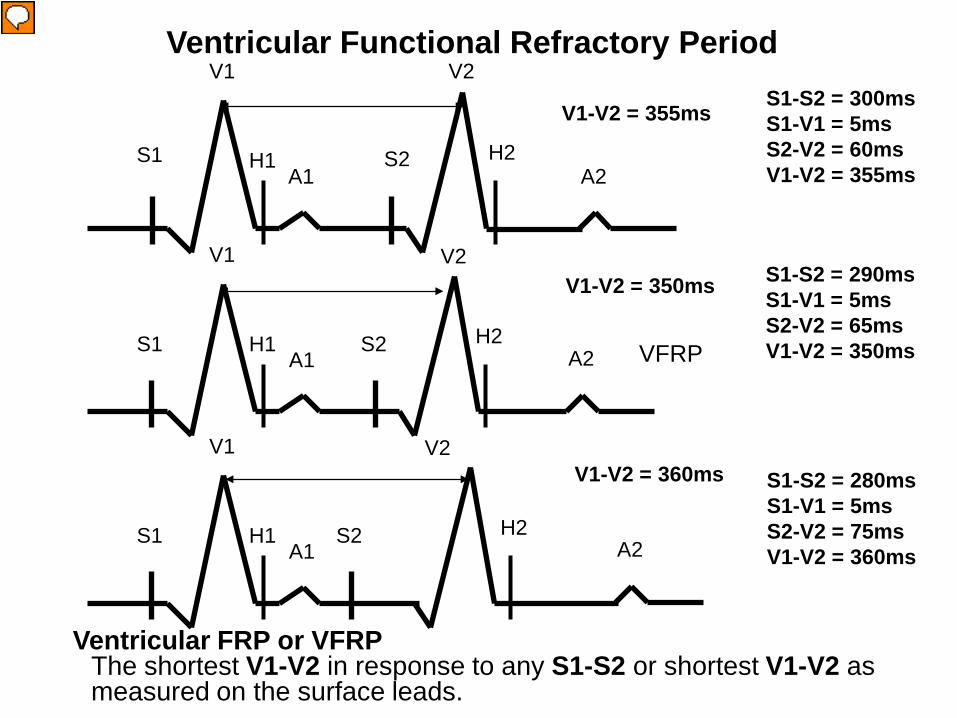
Retrograde Functional Refractory Periods: Retrograde Atrioventricular Nodal FRP or AVNFRP The shortest A1- A2 in response to any S1-S2. Ventriculoatrial Conduction System FRP or VAFRP The shortest A1- A2 in response to any H1-H2. Ventricular FRP or VFRP The shortest V1-V2 in response to any S1-S2 or shortest V1-V2 as measured on the surface leads.
Josephson, ME. Clinical Cardiac Electrophysiology, Techniques and Interpretations (3rd Edition), Lippincott, Williams and Wilkins, 2002, pp.39.
Presenter
Presentation Notes
Retrograde His-Purkinje System FRP or Retrograde HPFRP The shortest S1-H2 or H1-H2 in response to any V1-V2. Retrograde Atrioventricular Nodal FRP or AVNFRP The shortest A1- A2 in response to any S1-S2. Ventriculoatrial Conduction System FRP or VAFRP The shortest A1- A2 in response to any H1-H2. Ventricular FRP or VFRP The shortest V1-V2 in response to any S1-S2 or shortest V1-V2 as measured on the surface leads.
Retrograde Atrioventricular Nodal FRP or AVNFRP The shortest A1- A2 in response to any S1-S2
A1-A2 = 440ms
A1-A2 = 435ms
A1-A2 = 445ms
Presenter
Presentation Notes
Retrograde His-Purkinje System functional refractory period (Retrograde HPFRP): The shortest A1- A2 in response to any S1-S2. When the S1-S2 interval is 300ms the S2 stimulus produces a ventricular depolarization (V wave) followed by a His potential (H) and A wave. Note that the A1-A2 interval is 440ms. Also note that the H2-A2 interval which evaluates the retrograde AV node conduction in only 200ms. When the S1-S2 is decreased to 290ms, now the A1-A2 decreases slightly to 435ms and the H2-A2 has prolonged slightly to 205ms. However, when the S1-S2 is decreased to 280ms, now the A1-A2 increases to 440ms and the H2-A2 increases to 220ms. Since the retrograde AVNFRP is the shortest A1-A2 in response to any S1-S2, the retrograde AVNFRP is 290ms.
Ventricular FRP or VFRP The shortest V1-V2 in response to any S1-S2 or shortest V1-V2 as
measured on the surface leads.
V1-V2 = 355ms
V1-V2 = 350ms
V1-V2 = 360ms
Presenter
Presentation Notes
Ventricular functional refractory period (VFRP): The shortest V1-V2 in response to any S1-S2 or shortest V1-V2 as measured on the surface leads. In this slide when the S1-S2 interval is 300ms, the V1-V2 interval is 355ms. It can be calculated by adding the S1-S2 interval to the difference between the S1-V1 and S2-V2 intervals. In this case it is 300ms (S1-S2) + (60ms (S2-V2) - 5ms (S1-V1)) = 355ms. Once the S1-S2 interval is decreased to 290ms, the S2-V2 interval (15ms) becomes longer (65ms) , but the V1-V2 interval is only 350ms which is shorter than the V1-V2 interval for an S1-S2 of 300ms. Then when the S1-S2 interval is further decreased to 280ms, now the S2-V2 interval (75ms) prolongs even more since the S2 stimulus falls further into the VRRP. The resultant V1-V2 is now 360ms which is longer than that for an S1-S2 of 290ms. Since the VFRP is the shortest V1-V2 for any S1-S2, then in this case the FRP is 290ms.
49
Determination of the Effective Refractory Period
50
S1 S2 Physiology of the Heart, Katz, Ch.14; p. 248
Effective or absolute, (phase 2) (ERP) is the longest amount of time when cells cannot be depolarized again. The longest input that fails to conduct.
Atria 200-270 msecs Ventricles 200-270 msecs AV node 280-450 msecs Ch 22 intracardiac Eectrophysiology. John
Dimarco
Effective Refractory Period
Presenter
Presentation Notes
The effective (absolute) refractory period (ERP), which occurs during phase 2 of the action potential, is the longest amount of time when cells cannot be depolarized again. No matter how strong the stimulus the cell cannot depolarize. It is the longest input that fails to conduct. A general list of the various ERPs of the different locations in the heart are listed below (Chapter 22 Intracardiac Electrophysiology. John Dimarco): Atria 200-270 msecs Ventricles 200-270 msecs AV node 280-450 msecs The refractory periods are measured by either the incremental pacing method (short runs of straight pacing with the cycle length usually decreasing by 10-20 msec each cycle until the ERP is reached) or the extrastimulus method in which one early beat is inserted after a pacing train of 8-10 beats. The refractory period will change depending on the drive cycle length of the pacing train, so a drive cycle length close to the tachycardia cycle length may be chosen. In general however, most doctors use drive cycle lengths of 600ms and 400ms. For atrial, ventricular and His-Purkinje tissue, the ERP will shorten with faster drive cycle lengths, but for the atrioventricular node, with faster drive cycle lengths, the ERP will lengthen due to the fatigue phenomenon. Although the ERP is effected by drive cycle lengths in this predicted way, you will see later that abrupt changes will have a different effect on the ERP.
51
Effective Refractory Period Measurement
The ERP is measured using extrastimulus pacing with an early beat inserted following 8-10 beats at a fixed rate (pacing train). The pacing train allows the refractoriness to stabilize. This stabilization usually occurs after 3-4 beats. Also the current strength of the stimulus will influence the ERP. The greater the current strength, the shorter the ERP (in msec). The ERP will continue to shorten as the current increases, but eventually becomes fixed at further increases. Increasing the current strength to 10 mA usually results in shortening the ERP by 30 msec.
•(Josephson, ME. Clinical Cardiac Electrophysiology, Techniques and Interpretations (3rd Edition), Lippincott, Williams and Wilkins, 2002, pp.39-40.)
Presenter
Presentation Notes
The ERP is measured using extrastimulus pacing with an early beat inserted following 8-10 beats at a fixed rate (pacing train). The pacing train allows the refractoriness to stabilize. This stabilization usually occurs after 3-4 beats. Also the current strength of the stimulus will influence the ERP. The greater the current strength, the shorter the ERP (in msec). The ERP will continue to shorten as the current increases, but eventually becomes fixed at further increases. Increasing the current strength to 10 mA usually results in shortening the ERP by 30 msec. (Josephson, ME. Clinical Cardiac Electrophysiology, Techniques and Interpretations (3rd Edition), Lippincott, Williams and Wilkins, 2002, pp.39-40.)
52
ERP: Effect of Current Strength Atrial and ventricular ERPs decrease with the increased current strength of the impulse. Normal ERP measurements are taken at twice the diastolic threshold, but if the current strength is increased up to 10mA, the ERP will shorten on average by 30msec. The important thing is to be consistent with the method you use.
180 200 220 240 0
2
4
6
8
10
VERP (msec)
Cur
rent
(mA)
Josephson, M. Clinical Cardiac Electrophysiology, Techniques and Interpretations (3rd Edition), Lippincott, Williams and Wilkins, 2002, pp. 39-40.
Presenter
Presentation Notes
Atrial and ventricular ERPs decrease with an increased current strength of the impulse. Normal ERP measurements are taken at twice the diastolic threshold, but as stated in the previous slide, if the current strength is increased up to 10mA, the ERP will shorten on average by 30msec. The important thing is to be consistent with the method you use. In the graph shown in this slide you can see that up to a bit less than 2mA, the ERP progressively decreases, but after 2-5mA the ERP shortens only slightly and then above 5mA it will not shorten any further. (Josephson, M. Clinical Cardiac Electrophysiology, Techniques and Interpretations (3rd Edition), Lippincott, Williams and Wilkins, 2002, pp. 39-40.)
53
Affect of Pacing on the ERP ERP of atrial and ventricular tissue shortens
with pacing, allowing introduction of premature beats. ERP of AV node lengthens with pacing, and
results in blocking of conduction to the ventricles.
Presenter
Presentation Notes
Pacing’s effect on the ERP: ERP of atrial and ventricular tissue shortens with pacing, allowing introduction of premature beats. ERP of AV node lengthens with pacing, and results in blocking of conduction to the ventricles.
54
ERP Response to Different Cycle Lengths The ERPs of ventricular tissue and the His-Purkinje system differ in their response to different drive cycle lengths and extrastimuli (abrupt cycle length changes). Ventricular refractoriness demonstrates the cumulative effect of the preceding cycle lengths (several beats of a drive cycle), whereas the His-Purkinje system is effected greatly by the immediately preceding cycle length. Thus a change from a long to short cycle length will shorten both the His-Purkinje and ventricular ERPs, but a short to long cycle length will drastically prolong the His-Purkinje ERP, but will have only a slight effect if at all on the ventricular ERP. This is even more exaggerated if only a single extrastimulus is used. Below shows the effect on the His-Purkinje system.
Josephson, M. Clinical Cardiac Electrophysiology, Techniques and Interpretations (3rd Edition), Lippincott, Williams and Wilkins, 2002, pp. 40-44.
350 350 350 350 350
300 450 450 450
250 250 250 250 400
600 400 400 400
150 150 150 350
250 250 250 250
350 350 150
600 600 600 600
600 800 800
A. Constant CL
B. Long to short
C. Short to Long
Cycle length (CL)
Action Potential Duration (APD)
Diastolic Interval
His-Purkinje System
Effect on His-Purkinje System, but not on the VERP
Presenter
Presentation Notes
This slide shows the effect of various extrastimuli (abrupt cycle length changes) on the His-Purkinje system. The ERPs of ventricular tissue and the His-Purkinje system differ in their response to different drive cycle lengths and extrastimuli. Ventricular refractoriness demonstrates the cumulative effect of the preceding cycle lengths (several beats of a drive cycle), whereas the His-Purkinje system is effected greatly by the immediately preceding cycle length. Thus a change from a long to short cycle length will shorten both the His-Purkinje and ventricular ERPs, but a short to long cycle length will drastically prolong the His-Purkinje ERP, but have only a slight effect if at all on the ventricular ERP. This is even more exaggerated if only a single extrastimulus is used. The determinate factor of the ERP appears to be the length of the diastolic interval (the interval from the end of the action potential to the start of the next one).
55
The determinate factor of the ventricular ERP appears to be the diastolic interval. The ventricular refractory period (VERP) following one extrastimulus is shorter than that following two. In A, S2 hits making the diastolic interval only 40ms. Because it is short, it makes the resultant VERP shorter at 180ms. In B, the same thing occurs after S2, but when S3 is placed at the same cycle length as S1-S2 (260ms), because the VERP was only 180ms, the diastolic interval becomes 80ms. Since that is longer than the previous 40ms one, now the VERP is longer at 195ms. If this were the His-Purkinge system, the ERP both after the S2 and S3 would have been much more prolonged.
Josephson, M. Clinical Cardiac Electrophysiology, Techniques and Interpretations (3rd Edition), Lippincott, Williams and Wilkins, 2002, pp.44.
400ms 400ms 260ms
40ms
A
220ms 220ms 220ms 180ms
S1 S1 S1 S2
180ms 180ms
Coupling Interval:
VERP:
Diastolic Interval:
400ms 400ms 260ms
40ms
B
220ms 220ms 220ms 180ms
S1 S1 S1 S2 S3
180ms 180ms
Coupling Interval:
VERP:
Diastolic Interval:
195ms
80ms
260ms
ERP Response to Multiple Stimuli
Presenter
Presentation Notes
As mentioned in the previous slide, the determinate factor of the ERP appears to be the diastolic interval. The ventricular refractory period following one extrastimulus is shorter than that following two as shown in the diagram in this slide. In A, you see that S2 hits making the diastolic interval only 40ms. Because that is short, it makes the resultant ventricular refractory period (VERP) shorter at 180ms. In B, the same thing occurs after S2, but when S3 is placed at the same cycle length as S1-S2 (260ms), because the VERP was only 180ms, the diastolic interval becomes 80ms. Since that is longer than the previous 40ms one, now the VERP is longer at 195ms. If this were the His-Purkinje system, the ERP both after the S2 and S3 would have been much more prolonged. (Josephson, M. Clinical Cardiac Electrophysiology, Techniques and Interpretations (3rd Edition), Lippincott, Williams and Wilkins, 2002, pp.44.)
56
Effective Refractory Periods: Antegrade
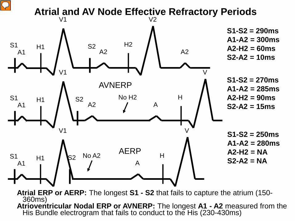
Antegrade Effective Refractory Periods: Atrial ERP or AERP: The longest S1 - S2 that fails to capture the atrium (150-360ms)
Atrioventricular Nodal ERP or AVNERP: The longest A1 - A2 measured from the His Bundle electrogram that fails to conduct to the His (230-430ms)
Atrioventricular conduction system (AVCS) ERP or AVERP: The longest S1 - S2 that fails to result in a ventricle depolarization
Josephson, ME. Clinical Cardiac Electrophysiology, Techniques and Interpretations (3rd Edition), Lippincott, Williams and Wilkins, 2002, pp.39.
Presenter
Presentation Notes
Atrial ERP or AERP: The longest S1 - S2 that fails to capture the atrium (150-360ms) Atrioventricular Nodal ERP or AVNERP: The longest A1 - A2 that fails to conduct to the His (230-430ms) HIS Purkinje System ERP or HPERP: The longest H1 - H2 that fails to conduct to the ventricle (330-450ms) Ventricular ERP or VERP: The longest S1 - S2 that fails to capture the ventricle (170-290ms) In general the ERP is first reached in the AV node, but that is not always the case and it is not unusual in a normal case for the ERP to be first reached in the His-Purkinje system because of the wide range of normal values.
Atrial ERP or AERP: The longest S1 - S2 that fails to capture the atrium (150-360ms)
Atrioventricular Nodal ERP or AVNERP: The longest A1 - A2 measured from the His Bundle electrogram that fails to conduct to the His (230-430ms)
Presenter
Presentation Notes
Atrial effective refractory period (AERP): When the S1-S2 interval is 290ms the S2 stimulus produces an atrial depolarization (A wave). As it is progressively decreased next to 270ms, the S2 still results in an A wave, but the conduction reaches the AV node ERP and blocks resulting in no His potential (H) or V wave. Thus the resultant AVNERP was 270ms. As the S1-S2 interval is further decreased to 250ms, now there is no A wave following S2, because the S2 fell in the ERP of the atrium. Thus, the atrial ERP (AERP) was 250ms in this example. Since 20ms decrements were used for the S1-S2 extrastimulation method, the doctor may go back and use 10ms decrements starting at about 300ms, to obtain a more precise measurement of the ERP. As the S1-S2 interval gets shorter and shorter, the S2 stimulus begins to fall in the atrial relative refractory period and thus the conduction time from the initiation of the stimulus to the resultant A wave (S2-A2) gradually increased as the S1-S2 interval is decreased. In the example above the S2-A2 interval increases from 10ms to 15ms as S1-S2 is decreased. The resultant atrial interval (A1-A2) will thus equal the S1-S2 interval plus the S2-A2 interval. The S1-A1 interval is close to 0ms because the S1-S1 interval is long (slow). This same phenomenon occurs in the following slides.
Atrioventricular effective refractory period (AVERP): The longest S1-S2 that fails to result in a ventricle depolarization. There are two ways the AVERP can be reached. One can be blocked in the AV node (AVNERP) and the other is block in the His-Purkinje System (HPERP). This example shows block in the AV node. This example show block in the AV node reaching the AVERP. When the S1-S2 interval is 310ms the S2 stimulus produces an atrial depolarization (A wave) followed by a His potential (H) and V wave. As it is progressively decreased next to 290ms, the S2 still results in an A wave, followed by an H and V wave showing that the AV node conduction is still intact. However, you will notice now that the A2-H2 interval is longer (A2-H2=80ms) than that observed with an S1-S2 of 310ms (A2-H2=50ms). This is occurring because the impulse falls in the relative refractory period of the AV node. When the S1-S2 interval is further decreased to 270ms, now there is block in the AV node resulting in an A wave, but no H potential or V wave. Thus, since the longest S1-S2 failing to result in a ventricular depolarization was 270ms, that is the AVERP. In this case it is the same as the AVNERP. The other example of an AVERP would be the HPERP in the next slide. The AVERP is not only used to evaluate the normal conduction system, but it is also used to evaluate accessory pathway conduction. The AVNERP only evaluates the AV node conduction and the HPERP only evaluates the His-Purkinje conduction.
59
Retrograde Effective Refractory Periods:
Retrograde His Purkinje System ERP or Retrograde HPERP: The longest S1 - S2 or V1-V2 in which S2 or V2 block below the bundle of His. Can only measure if H2 is recorded before the retrograde block. Retrograde AV Node ERP or Retrograde AVNERP: The longest S1 - H2 or H1-H2 that H2 fails to conduct to the atrium Ventriculoatrial Conduction System (VACS) ERP or VAERP: The longest S1 - S2 that fails to conduct to the atrium Ventricular ERP or VERP: The longest S1 - S2 that fails to capture the ventricle (170-290ms)
Josephson, ME. Clinical Cardiac Electrophysiology, Techniques and Interpretations (3rd Edition), Lippincott, Williams and Wilkins, 2002, pp.39.
Effective Refractory Periods: Retrograde
Presenter
Presentation Notes
Retrograde His Purkinje System ERP or Retrograde HPERP: The longest S1 - S2 or V1-V2 in which S2 or V2 block below the bundle of His. Can only measure if H2 is recorded before the retrograde block. Retrograde AV Node ERP or Retrograde AVNERP: The longest S1 - H2 or H1-H2 that H2 fails to conduct to the atrium Ventriculoatrial Conduction System (VACS) ERP or VAERP: The longest S1 - S2 that fails to conduct to the atrium Ventricular ERP or VERP: The longest S1 - S2 that fails to capture the ventricle (170-290ms) In general the retrograde ERP is first reached in the AV node, but that is not always the case and it is not unusual in a normal case for the retrograde ERP to be first reached in the His-Purkinje system because of the wide range of normal values.
Retrograde AV Node ERP or Retrograde AVNERP: The longest S1 - H2 or H1-H2 that H2 fails to conduct to the atrium
Presenter
Presentation Notes
Retrograde AV Node effective refractory period (VAERP): The longest S1-H2 or H1-H2 that H2 fails to conduct to the atrium When the S1-S2 interval is 290ms the S2 stimulus produces an ventricular depolarization (V wave) followed by a His potential (H) and A wave. As it is progressively decreased next to 270ms, the S2 still results in an V wave, followed by an H and A wave showing that the AV node conduction is still intact. However, you will notice now that the H2-A2 interval is longer (H2-A2=90ms) than that observed with an S1-S2 of 290ms (H2-A2=60ms). This is occurring because the impulse falls in the relative refractory period of the AV node. When the S1-S2 interval is further decreased to 250ms, now the conduction reaches the AV node ERP and blocks resulting in a His potential but no A wave. This means that the conduction blocked in the AV node and not the His-Purkinje system. Thus the retrograde AVNERP was 250ms in this example.
Ventriculoatrial Conduction System (VACS) Effective Refractory Period: Block in the AV Node (VAERP): The longest S1-S2 that fails to conduct to the atrium. There are two ways the VAERP can be reached. One can be block in the AV node (AVNERP) as in this example and the other one where there is block in the His-Purkinje System (HPERP). When the S1-S2 interval is 290ms the S2 stimulus produces an ventricular depolarization (V wave) followed by a His potential (H) and A wave. As it is progressively decreased next to 270ms, the S2 still results in an V wave, followed by an H and A wave showing that the AV node conduction is still intact. However, you will notice now that the H2-A2 interval is longer (H2-A2=90ms) than that observed with an S1-S2 of 290ms (H2-A2=60ms). This is occurring because the impulse falls in the relative refractory period of the AV node. When the S1-S2 interval is further decreased to 250ms, now the conduction reaches the AV node ERP and blocks resulting in a His potential but no A wave. This means that the conduction blocked in the AV node and not the His-Purkinje system. Thus the VAERP was 250ms in this example. Unlike the retrograde AVNERP (which only evaluates AV node conduction) and the retrograde HPERP (which only evaluates the His-Purkinje system conduction), the VAERP can be used to evaluate accessory pathway conduction as well.
VERP S1-S2 = 230ms V1-V2 = NA H2-A2 = NA S2-V2 = NA S1
V1
A1 S2 No V2 H1
A H
V
Ventricular Effective Refractory Period
Ventricular ERP or VERP: The longest S1 - S2 that fails to capture the ventricle (170-290ms)
Presenter
Presentation Notes
Ventricular effective refractory period (VERP): The longest S1-S2 that fails to capture the ventricle (170-290ms). When the S1-S2 interval is 270ms the S2 stimulus produces an atrial depolarization (A wave) (A2). As it is progressively decreased next to 250ms, the S2 still results in a ventricular potential (V wave), but the conduction reaches the AV node ERP and blocks resulting in no A wave. Thus the resultant VAERP was 250ms. As the S1-S2 interval is further decreased to 230ms, now there is no V wave following S2, because the S2 fell in the ERP of the ventricle. Thus, the ventricular ERP (VERP) was 230ms in this example. As the S1-S2 interval gets shorter and shorter, the S2 stimulus begins to fall in the ventricular relative refractory period and thus the conduction time from the initiation of the stimulus to the resultant V wave (S2-V2) gradually increased as the S1-S2 interval is decreased. In the example above the S2-V2 interval increases from 15ms to 30ms as S1-S2 is decreased. The resultant ventricular interval (V1-V2) will thus equal the S1-S2 interval plus the S2-V2 interval. The S1-V1 interval is close to 0ms because the S1-S1 interval is long (slow).
63
Performing a Basic EP Study
Programmed Electrical Stimulation Baseline EGM Recordings Refractory Periods Sinus Node Recovery Time (SNRT) Sinoatrial Conduction Time (SACT) Basic EP Tasks
64
What is an EP Study?
Electrical stress test An invasive study to assess the
heart’s electrical conduction system Patient under conscious sedation Often classified outpatient Done in EP lab, part of cardiac cath labs
65
Why Conduct an EP Study?
To evaluate conduction system function To confirm supraventricular tachycardia To evaluate ventricular tachyarrhythmias To classify the extent of bradycardia To test efficacy of antiarrhythmic drugs To test efficacy of implanted devices
Presenter
Presentation Notes
Performing an electrophysiological study (EPS): EPS are performed to determine the mechanissm of arrhythmias. Often it cannot be diagnosed by the 12 lead ECG and an EPS is performed to find the exact mechanism. When the exact mechanism is not known, they call it a paroxysmal supraventricular tachycardia (PSVT). The EPS can tell exactly which arrhythmia it is. EPS is also used to determine an effective antiarrhythmic medication to treat an arrhythmia. EPS can be performed to induce certain arrhythmias such as VT (called an induction or VT study) and see if various drugs can suppress the arrhythmia. The patients are sent home and brought back at a later date to undergo a repeat EPS to see if the drug still works and if not other drugs would be tried. EPS can also be performed to evaluate VTs that cause excessive ICD shocks. Antiarrhythmic agents may be trialed or catheter ablation may be attempted. In the EPS various types of atrial and ventricular pacing are performed to first determine the basic electrophysiology measurements, next to determine conduction properties and refractory periods, and last to induce arrhythmias.
66 66
ACC/AHA Guidelines
EP study Indications
67
Which Type of EP Study?
Clinical Presentation Documented SVT or
atrial flutter Suspected SVT Syncope
Nonsustained VT Suspected brady
Recommended Study Comprehensive EPS
with ablation Comprehensive EPS Tilt, Baseline EPS, or
loop recorder Baseline EPS Baseline EPS only if VT
suspected
68
EP Study Outcomes
Therapy Device
Therapy Surgical Therapy
Pharmacologic Therapy
Device Implant
Catheter Ablation
No Therapy
EP Study
69
Basic Steps in an EP Study
Equipment in room and functional Patient info in recording system Check plan with physician Gather sheaths, catheters, connectors Patient in room and prepped Prep sterile table, open products Sedate patient Catheters placed with acceptable thresholds Baseline intervals and stimulation protocols Ablate, wait, re-test Pull and hold
70
TESTING USED IN EPS
71
Electrophysiology Study Measurement of baseline conduction intervals Atrial Pacing - Assessment of SA nodal automaticity and
conductivity - Assessment of AV nodal conductivity and
refractoriness - Assessment His-Purkinjie system conductivity and
refractoriness - Assessment of atrial refractoriness
Evaluate sinus node function Evaluate antegrade AV node conduction Evaluate retrograde AV node conduction
74
Catheters used in standard EP studies: Quadripolar in the HRA (usually fixed curve) Quadri, hexa, octa, or decapolar at the HBE (fixed curve or steerable) Quadripolar in the RVA (usually fixed curve) Hex, octa, or decapolar in the CS (fixed curve or steerable)
Catheters used in a EP Study
75
Catheters used in SVT studies: Quadripolar in the HRA (usually fixed curve) Quadri, hexa, octa, or decapolar at the HBE (fixed curve or
steerable) Quadripolar in the RVA (usually fixed curve) Hex, octa, or decapolar in the CS (fixed curve or steerable) Steerable large tip (4mm) mapping catheter
Catheters used in VT studies: Quadripolar in the HRA (sometimes omitted) Quadripolar (most common) at the HBE (fixed or steerable) Quadripolar in the RVA (steerable is common so that it can
be moved to the RVOT) Steerable large tip (4mm) mapping catheter
Catheters used in SVT and VT Studies
76
Evaluate sinus node function Sinus node recovery time (SNRT) Sino-atrial conduction time (SACT)
Evaluate antegrade AV node conduction AV Decremental Properties AVNERP AERP AV Wenckebach cycle length (Incremental pacing only)
Evaluate retrograde AV node conduction (S1S2 and Incremental pacing) VAERP VERP VA Wenckebach cycle length (Incremental pacing only)
Standard Conduction System Study
77
Standard EP Study Protocol Atrial Pacing
Atrial pacing is performed with the HRA catheter to determine the following:
– AV decremental properties – AVNERP – AV Wenckebach cycle length – AERP
Pacing spike A wave
78
For SA node evaluation two tests are performed – SNRT – SACT
If just one of these tests are performed, the evaluation of the SA node may not be accurate, therefore it is recommended to perform both
Since the autonomic nervous system can highly influence these tests, it is recommended to perform a pharmacological blockade to observe the true state of the SA node – Atropine to eliminate the parasympathetic influence – Propranolol to eliminate the sympathetic influence
Depending on the results of these tests, a pacemaker may be implanted, so a correct evaluation should be made
Standard Conduction System Study - Antegrade Stimulation
79
Sinus node recovery time (SNRT) – time it takes for the SA node to recover from overdrive suppression of normal automaticity. Test: To suppress SA nodal automaticity, overdrive pacing impulses are delivered via
the HRA at a rate faster than the intrinsic sinus rate at a constant rate for at least 30 seconds; then abruptly stopped and the SNRT measured. The SNRT is the longest pause between the last paced beat and the first intrinsic beat after overdrive pacing ends. SNRT measurements are typically taken at 800, 700, 600, 500, 450, 400, 350 and possibly 300 ms intervals. The longest interval observed during recovery is the SNRT. An SNRT longer than 1,500 ms is considered abnormal.
Since the first cycles after the sinus node recovery are usually slightly longer than the BCL, either a corrected sinus node recovery time (CSNRT) or an SNRT:BCL ratio is used as below:
CSNRT = SNRT – BCL A CSNRT longer than 525 ms is considered abnormal. SNRT / BCL x 100%. A ratio greater than 160% is considered abnormal.
Standard Conduction System Study – Sinus Node Recovery Time (SNRT)
Presenter
Presentation Notes
The sinus node recovery time (SNRT) is the time it takes for the SA node to recover from overdrive suppression of normal automaticity. To suppress SA nodal automaticity, pacing impulses are delivered via the HRA catheter at a rate faster than the intrinsic sinus rate (called overdrive pacing). Overdrive pacing is continued at a constant rate for at least 30 seconds; then abruptly stopped and the SNRT measured. The SNRT is the longest pause between the last paced beat and the first intrinsic beat after overdrive pacing ends. SNRT measurements are typically taken at 800, 700, 600, 500, 450, 400, 350 and possibly 3000 ms intervals. The longest interval observed during recovery is considered the SNRT for the patient. An SNRT longer than 1,500 ms is considered abnormal. The first cycles after sinus node recovery are usually slightly longer than the patient’s BCL. Thus, EPs use either a corrected sinus node recovery time (CSNRT) or an SNRT:BCL ratio, calculated as follows: CSNRT = SNRT – BCL A CSNRT longer than 525 ms is considered abnormal. SNRT / BCL x 100%. A ratio greater than 160% is considered abnormal.
Standard Conduction System Study – Sinus Node Recovery Time (SNRT)
81
SA Node (with pacemaker cells)
Transitional cells
Last pacing impulse
Conduction from the atrium into the SA
node Conduction from the SA
node to the atrium
Standard Conduction System Study – Sinoatrial Conduction Time (SACT)
Sinoatrial conduction time (SACT) – time it takes for a sinus impulse to conduct through perinodal (surrounding) atrial tissue When SA node disease (sick sinus syndrome) occurs, it is due to poor conduction
in the transitional cells and not failure of the pacemaker cells firing A prolonged SACT suggests sinus exit block.
82
Return cycle
SCL A A
Pace from the HRA catheter at a rate slightly above the sinus rate for 30 - 60 seconds and then stop abruptly and measure from the last pacing spike to the first sinus A wave
Last pacing spike First sinus A wave
SA Node (PAcells) Transitional cells
Conduction from the atrium into the SA node
Conduction from the SA node to the atrium
A A
Standard Conduction System Study – Sinoatrial Conduction Time (SACT)
83
SA Node (PAcells) Transitional cells
A A
SACT = the return cycle (last S1 to the first sinus A wave) minus the SCL and then divided by 2 (i.e. A + A) *SCL = A-A interval measured on the HRA catheter in sinus rhythm
A = SACT (normal 50-125ms)
Return cycle
SCL A A
Standard Conduction System Study – Sinoatrial Conduction Time (SACT)
84
After completing the SA node evaluation, the doctor will use both extrastimulus pacing and incremental pacing Both antegrade (atrial pacing) and
retrograde (ventricular pacing) studies will be performed.
Standard Conduction System Study – Antegrade Extrastimulus Pacing
85
Antegrade study – Extrastimulus pacing: The HRA catheter is used to deliver single
extrastimulation (S2) following an 8-10 beat pacing train (S1) during sinus rhythm to assess the AV node and atrial conduction properties. This is often performed at 2 different cycle lengths (Ex. 600 and 500 ms) and up to 300bpm (200ms) or the AERP to assess the following: AV Activation AV Decremental Conduction AVNERP AERP
– Incremental pacing: The HRA catheter is used to deliver incremental pacing with progressive increases in the rate by decreasing the pacing cycle length (S1-S1) by 10-20ms decrements to assess the following: AV Activation AV Decremental Conduction AV Wenckebach cycle length AVNERP AERP
Standard EP Study Protocol Antegrade Study
86
S1-S2
AH interval prolongs
With the AV decremental property, as the pacing rate is increased, eventually the rate of conduction will progressively slow, as seen by progressively longer and longer AH intervals as the S1-S2 or S1-S1 pacing interval is increased. This prolongation indicates the pacing has entered the releative refractory period.
Standard EP Study Protocol AV Decremental Conduction
87
With Wenckebach there are grouped beats with gradual prolongation of the AH interval until conduction to the ventricle eventually drops. Therefore only an occasional “A” wave will not conduct to produce a “V” (see the dropped “V” above). This occurs as pacing is hitting far into the relative refractory period.
AH Intervals
Dropped beat
Standard EP Study Protocol AV Wenckebach
88
The ERP of the AV node is reached when conduction from the atrium to the ventricle is blocked due to reaching the refractory period of the AV nodal tissue. This would be evidenced by an “A” wave after the pacing spike not followed by a His potential or a “V” wave. AVNERP = 280 - 450 msecs
No His or “V”
Pacing spike
Standard EP Study Protocol AVNERP
A V
89
This is the longest A1-A2 that fails to conduct
This A1-A2 is longer but it DOES conduct
To identify the ERP of the AV Node a series of programmed stimulation trains are conducted to find the longest A1-A2 interval that fails to conduct to the His. Identifying the ERP of other cardiac tissues is done in the same fashion:
Atrial ERP (AERP): The longest S1 - S2 that fails to capture the atrium Ventricular ERP (VERP): The longest S1 - S2 that fails to capture the ventricle.
ERP of the AV Node
Standard EP Study Protocol AVNERP
145
Presenter
Presentation Notes
As such, the definition of the AV node refractory period is the longest A1-A2 interval that fails to conduct to the His, not the pacing interval (S1-S2).
90
AERP No local atrial electrogram Pacing “spike”
Standard EP Study Protocol AERP
AERP = 200 - 270 msecs
91 91
AVNERP
AERP
Standard EP Study Protocol AVNERP and AERP
92
Standard EP Study Protocol Effective Refractory Periods
ERPs of the various cardiac tissue
Atria 200-270 msecs Ventricles 200-270 msecs AV node 280-450 msecs
Ch 22 intracardiac Eectrophysiology. John Dimarco
93 This sequence is showing evidence of what?
93
Standard EP Study Protocol AH Jump
AH = 80msec
AH = 90msec
AH = 180msec
94
Retrograde study – Extrastimulus pacing: The RVA catheter is used to deliver single
extrastimulation (S2) following an 8-10 beat pacing train (S1) during sinus rhythm to assess the VA and ventricular conduction properties. This is often performed at 2 different cycle lengths (Ex. 600 and 500 ms) and up to 250bpm (240msec) or the VERP to assess the following: VA Activation VA Decremental Conduction VAERP VERP
– Incremental pacing: The HRA catheter is used to deliver incremental pacing with progressive increases in the rate by decreasing the pacing cycle length (S1-S1) by 10-20ms decrements to assess the following: VA Activation VA Decremental Conduction VA Wenckebach cycle length VAERP VERP
Standard Conduction System Study Retrograde Study
95
– Right Ventricular Straight Pacing performed to Check and set pacing thresholds Check to see if the AV Node works backwards (retrograde conduction) Check to see if there is an accessory pathway with retrograde
conduction (if no conduction can go retrograde up the normal conduction system, yet you see retrograde conduction, then it means there is an accessory pathway) Do “rescue” pacing Terminate or induce tachycardias
Standard EP Study Protocol Retrograde Conduction Study
Presenter
Presentation Notes
check and set pacing thresholds: this is done the same way as atrial thresholds, and for the same reasons. check to see if the AV Node works backwards (retrograde conduction); occurs in 40%-90% of patients*; VA Conduction through the node is essential in some tachycardias. Also, a “retrograde WBK” cycle length can sometimes be determined. check to see if there is anything else that conducts backwards (there shouldn’t be; if there is then the patient has a “retrograde bypass tract”); do “rescue” pacing (in case you need to save someone’s life and you can’t find your temporary pacing box). Most companies that make stimulators have a disclaimer about using their device to “rescue” pace, since they don’t work quite the same a s temporary pacers (they can’t “inhibit”); if your patients’ heart stops beating for whatever reason, use it anyway. Switch over to the appropriate device after everything calms down. terminate tachycardia (see next slide) *Clinical Cardiac Electrophysiology, 3rd Edition, Lippincott, Williams and Wilkins,2002, p35
96
In this example pacing is being performed from the right ventricular apex (RVA). Therefore you will first have a “V” wave. Conduction will then conduct up the conduction system resulting in a His potential and then an “A” wave. This is called retrograde conduction. However, although it is a normal phenomenon, not everyone has retrograde conduction.
V A
V A
Standard EP Study Protocol Retrograde Conduction Study – Ventricular Pacing
97
V A V A V A V V A V
No “A” wave
Note that on the 4th and 6th beats no “A” wave follows the “V” wave. This is called VA block.
Standard EP Study Protocol Retrograde Conduction Study – VA Block
98
Just as when you pace faster and faster from the atrium, when you pace at faster and faster rates in the ventricle, you will have decremental conduction. That is, as you pace faster and faster, the VA or HA interval will progressively prolong the faster you go. This is because as you begin to enter the relative refractory period (RRP) of the AV node, conduction begins to slow. The further into the RRP you pace, the slower the conduction. In the example above, you can see that the VA and HA (not easily seen) widened with the shorter (faster) pacing interval.
V H A V HA
Standard EP Study Protocol Retrograde Conduction Study – VA Decremental Conduction
99
VERP
Pacing “spike”
No local ventricular electrogram
VERP = 200 - 270 msecs
Standard EP Study Protocol Retrograde Conduction Study – VERP
The ventricular ERP (VERP) is reached when you pace at a rate faster than the absolute refractory period of the ventricular tissue. This would be evidenced by a pacing spike not followed by a “V” wave. Consequently there would be no His potential or “A” wave.
100
Arrhythmia Induction
101
1. 1 or 2 extrastimuli (S2 and S3) during SR from the RV apex 2. 1 or 2 extrastimuli (S2 and S3) during ventricular pacing (S1) at
100, 120 and 150 bpm (600, 500 and 400msec) from the apex 3. Incremental pacing from RV apex up to 250bpm (240msec) in
10-20msec decrements 4. 1 or 2 extrastimuli (S2 and S3) during SR from the HRA 5. 1 or 2 extrastimuli (S2 and S3) during atrial pacing (S1) at 100,
120, and 140 bpm (600,500,400msec) from the HRA 6. Incremental pacing from the HRA up to Wenckebach or 300
bpm (200msec), or until an arrhythmia is initiated in 10-20msec decrements
7. Repeat steps 4-6 from the CS or left atrium 8. If not inducible with above give an isoproterenol infusion at a
rate of 1 to 6 µg/min to increase patients’ heart rate to at least 20% above the resting sinus rate or shorten the sinus CL to 450 msec and repeat steps 1-7
Standard EP Study Protocol Cont. – Arrhythmia Induction - SVT
102
Atrial Protocol 1.1 extrastimuli (S2) during SR from the HRA 2.1 extrastimuli (S2) during atrial pacing at 100, 120 and 150 bpm (600, 500
and 400msec) from the HRA 3.Incremental pacing from the HRA up to the Wenckebach point, or 300
bpm (200msec), or initiation of SVT in 10-20msec decrements
Ventricular Protocol 1.1 - 2 extrastimuli (S2 and S3) during SR from the RV apex 2.1 - 2 extrastimuli during ventricular pacing at 100, 120 and 150 bpm (600,
500 and 400msec) from the RV apex 3.Incremental pacing from RVA up to 250bpm (240msec) in 10-20msec
decrements 4.3 extrastimuli (S2, S3 and S4) during SR from the RV apex 5.3 extrastimuli (S2, S3 and S4) during ventricular pacing at 100, 120 and
150 bpm (600, 500 and 400msec) from the RV apex 6.Repeat steps 1-5 from the right ventricular outflow tract 7.If not inducible with above give an isoproterenol infusion starting at a rate
of 2.5µg/min to increase patients’ heart rate to at least 20% above the resting rate and repeat steps 1-6
Standard EP Study Protocol Arrhythmia Induction - VT
103
In an EP study various types of pacing are used to induce the arrhythmias so that it can be evaluated for its type and origin. In the example above a single (S2) extrastimulus is used to induce the arrhythmia.
Standard EP Study Protocol Cont. – Arrhythmia Induction
104
EP Protocol: • Measure baseline conduction intervals (BCL, IACT, AH, HV, QRS and
QT) in sinus rhythm • Ventricular extrastimulus testing (VAERP, VERP, and retrograde
conduction) • Incremental ventricular pacing (VA conduction, VAERP, VERP, VA
Wenckebach, FRP) - Pace at a rate slightly faster than the BCL and increase until VA block. Pacing is typically no faster than 240 ms.
• PES in the ventricle (arrhythmia induction) - Drive train (S1) of 600, 500 and then 400 ms with extrastimuli until the VERP. • Ventricular burst pacing (fixed, incremental or decremental – arrhythmia
induction). • Atrial extrastimulus testing to measure the AV nodal and atrial
refractory periods. • Incremental atrial pacing to assess AV and atrial conduction
(AVNERP, AV Wenckebach, AERP)- Pace at a rate slightly faster than the BCL and decrease until AV block, but not faster than 200 ms.
• PES in the atrium (arrhythmia induction) - Drive train (S1) of 600, 500 and 400 ms with extrastimuli. • Atrial burst pacing (fixed, incremental or decremental-arrhythmia
induction).
Standard EP Study Protocol Cont. – Basic EP Tasks - Summary
Presenter
Presentation Notes
EPs develop there own study protocols over time and individualize the protocol to baseline findings and the patient’s clinical history. Most EPs perform the following tasks: Measure baseline conduction intervals, including the BCL, IACT, AH, HV, QRS and QT. Conduct ventricular extrastimulus testing to measure the effective and functional ventricular refractory periods and determine if retrograde conduction is present. Perform decremental ventricular pacing to assess VA conduction. Pacing pulses are delivered at a rate slightly faster than the BCL and increased until VA block is achieved. Pacing is typically no faster than 300 ms. Perform PES in the ventricle. A drive train (S1) of 600, 500 and then 400 ms may be used with extrastimuli. Perform burst pacing (fixed, incremental or decremental). Conduct atrial extrastimulus testing to measure the AV nodal and atrial refractory periods. Perform decremental atrial pacing to assess AV conduction. Pacing pulses are delivered at a rate slightly faster than the BCL and decreased until AV block is achieved. Typically, pacing is not faster than 300 ms. Perform PES in the atrium. A drive train (S1) of 600, 500 and then 400 ms may be used with extrastimuli. Perform burst pacing (fixed, incremental or decremental).
105
Induction of Reentrant Arrhythmias
106
Reentry Requirements Reentry circuits consist of a fast
pathway and slow pathway and reentry requires an area of “slow” conduction with a short refractory period – this could be caused by:
The AV Node; An area of disease; Or, simply a physically longer path
(like this example). The fast pathway has fast
conduction, but a long refractory period – This can be the:
Fast pathway of the AV node Accessory Pathway Atrial tissue Or a shorter path (as in the example)
Note how the wavefront cancels out in the longer path (slow pathway)
This is a longer path to this point...
…than this one
107
Requirements for Reentry
Two limbs joined at their ends One conducts more slowly but
has a shorter refractory period
The other conducts faster but has a longer refractory period Unidirectional block in one limb
“Sinus” “Reentry”
http://rezidentiat.3x.ro/eng/tulbritmeng.htm
Presenter
Presentation Notes
These two movies help elucidate the substrate needed for reentry. The left one shows the self-canceling effect of the wave front in the longer limb due to the normal impulse “turning the corner” and causing a collision with the wave traveling in the slower/longer path. The net effect is that the “long” path will be of no consequence. The second (right) movie shows unidirectional block in the regular/short/normal/fast pathway, which subsequently allows the wave traveling in the alternate path to reenter the circuit after the prior path recovers. There are then two complete circuits made in the “tachycardia” circuit.
108
Reentry Requirements
Reentry requires an area of unidirectional block- – this also can come
from the AV Node or disease, as well as normal variations in refractoriness in the presence of an abnormal structure (bypass tract).
Presenter
Presentation Notes
This is where the “differences in refractoriness between the two limbs of the circuit” statement comes in to play.
109
Reentry Requirements
Reentry requires a complete circuit that has both an area of “slow” conduction and Unidirectional block in it.
110
Terminating a Reentrant Circuit
Pacing Pharmacological (Ex. Adenosine) Ablation…
– Eliminates the complete circuit.
111
Reentrant Circuits and Pacing Maneuvers – Resetting and Advancing the Tachycardia
“Resetting” or “Advancing” a tachycardia:
If you can pace faster than the tachycardia and speed the tachycardia up to the pacing rate with one or more beats (entrainment) thus resetting or advancing the tachycardia, then the mechanism is reentry.
Presenter
Presentation Notes
The placement of a single pacing impulse into a tachycardia circuit that does not terminate it, but effects the tachycardia in some fashion is called “resetting” or “advancing” the tachycardia. This maneuver is dependent on the impulse traveling in the same direction as the tachycardia wavefront (as opposed to the opposite direction, or both directions, as in the stimulation termination example).
112
Reentrant Circuits and Pacing Maneuvers – Resetting and Advancing the Tachycardia
113
Entrainment: – The placement of several pacing impulses
into a tachycardia circuit that does not terminate it.
The intent of entrainment is to determine if the pacing site is in the tachycardia circuit… If the pacing site is in the circuit, it might
be an effective ablation site
Reentrant Circuits and Pacing Maneuvers – Entrainment
Presenter
Presentation Notes
There are several criteria that must be satisfied for the maneuver to qualify as entrainment (most of which are summarily ignored outside of academic institutions) that are beyond the scope of this presentation. Entrainment is roughly akin to- you pedaling a stationary bicycle at a constant speed (the tachycardia cycle length); someone (the person running the stimulator) grabbing a hold of a pedal and spinning it slightly faster than you are pedaling (the pacing cycle length); thereby making your feet go faster than they were by themselves; and then letting go, allowing your feet to immediately return to their previous rate (post pacing cycle length). (this sounds like something a little brother would do…) if it is, there will be NO CHANGE in the shape (“morphology”) of the surface ECG or the activation sequence on the intracardiac recordings; the only change will be in the RATE. …if it is not, the recordings will look different than the tachycardia. *(that does not necessarily mean that it is safe…)
114
Entrainment is continuous pacing during a tachycardia that accelerates the activation to the pacing cycle length and does not terminate the arrhythmia.
The ability to entrain a tachycardia supports reentry as the tachycardia mechanism.
Entrainment pacing can occur outside of or within the actual tachycardia circuit.
If it occurs outside the circuit, the ECG will be a combination of the tachycardia morphology and what the morphology would look like when pacing in normal sinus rhythm (fusion).
If entrainment occurs within the circuit, the ECG morphology remains constant (concealed entrainment).
Reentrant Circuits and Pacing Maneuvers – Entrainment
115
This is a demonstration of pacing with fusion.
Reentrant Circuits and Pacing Maneuvers – Entrainment – Pacing with Fusion
116
This is a demonstration of pacing with concealed entrainment.
Reentrant Circuits and Pacing Maneuvers – Entrainment – Pacing with Concealed Entrainment
117
This is known as the Return Cycle Length, or the Post Pacing Interval (PPI) and it is the time it takes for the tachycardia to resume after pacing is stopped.
If the pacing occurred outside of the tachycardia circuit, the time it takes for the tachycardia to resume will be longer than if it were inside the circuit.
The reentry circuit = Tachycardia cycle length (TCL)
Time from pacing site to the circuit
PLUS
Time from circuit to the pacing site
PLUS
=Return Cycle Length
= pacing site
Return cycle length= (Time from pacing site)x2 +TCL
Reentrant Circuits and Pacing Maneuvers – Entrainment – Post Pacing Interval
118
If the pacing occurred inside of the tachycardia circuit, the time it takes for the tachycardia to resume will be the tachycardia cycle length only, since there is no distance outside of the circuit to add time. A PPI < 30 msec is considered in the tachycardia circuit.
The reentry circuit = Tachycardia cycle length (TCL)
Return cycle length= (Time from pacing site)x2 +TCL
PLUS
Time from pacing site to the circuit (in this case it’s 0)
PLUS
Time from circuit to the pacing site (also 0)
=Return Cycle Length
Reentrant Circuits and Pacing Maneuvers – Entrainment – Post Pacing Interval
119
PPI :Post pacing interval FCL: Flutter cycle length
15. Lesh et al. JCE Vol.7,No 4, April 1996
Reentrant Circuits and Pacing Maneuvers – Concealed Entrainment – Post Pacing Interval = TCL
Presenter
Presentation Notes
TA 1-20 : 20 pole electrode catheter TA1,2 at low anterolateral right atrium (7:30 o'clock) Pacing from 7:00 o'clock at 200 msec CL results in entrainment (first 3 beats) the morphology at the recording site during pacing capture (transient entrainment) and during spontaneous atrial flutter is unchanged, indicating that activation of this site occurs the same way during pacing as it does during spontaneous atrial flutter