electrophoretic displays (epd) - ترجمه...
TRANSCRIPT

1
Electrophoretic displays (EPD)
Display device is an output device for displaying information as visible or palpable
such as Braille screen for blinds. Color or black and white images can be displayed
by different devices that take electrical signals as an input and produce images on
the screen. Among the display devices, Electronic Display or E-paper are a range of
technologies on the screen that create an image similar to the effect of the ink on the
paper. It is very similar to the paper so that it has used even the same color material
in the printing industry. Electrophoretic Displays perform in active or passive
modes. In this case, passive displays keep their image without the need to power
consumption and the active displays use an electric current to display the image [1].
These display devices only reflect the ambient light like the ordinary papers and
unlike the typical screens which have light. Many of these papers can show the fixed
texts and images without the use of electricity indefinitely. Reading the electronic
papers is easier than normal screens owing to the constantly changing the images,
greater viewing angles and reflection of the ambient light instead of illumination of
the screen. The writings of a good E-paper are not fade in the sunlight. The contrast
ratio of the electronic papers that are presented up to the 2008 is similar to the
newspaper, although this ratio is a little better in the newer electronic papers. Of
course, the electronic paper should not be confused with the digital paper that is a
screen to create handwritten digital documents using a digital pen. Hence, much
attention is focused on the "electronic papers" in the EPD displays technology
nowadays [2, 6]. Figure 1-1 shows one example of electronic paper [7].
In the past decades, much attention is focused on the Electrophoretic displays
(EPDs) instead of ordinary paper due to the low cost, low weight, low power
consumption and its safety. EPDs are of reflective displays that act based on the

2
migration of charged suspension particles in the dielectric fluid towards the
oppositely charged electrode and this is called electrophoresis phenomenon [2, 7,
and 9].
The so-called electrophoresis refers to the movement of suspended charged particles
in the suspension fluid under the influence of an electric field. Whenever the electric
field between the electrodes used in a cell, the particles migrate according to the
electrical charge and the suspension fluid remains stable [2, 10].
In displays based on the electrophoretic inks, the suspension fluid and particles in
the capsules or microcapsules immigrate under the influence of the applied electric
field [11, 12].
In general, electrophoretic displays containing color suspensions or dispersed
charged particles in a dielectric media that create Color Contrasting in a cell
consisting of two conductive electrodes with transparent and parallel plates that have
been placed with a specified distance of about Micron.
Since 1960, the electrophoretic displays (EPDs) are developed as a sort of reflective
display. Their images can be repeatedly electrically written or erased. This
technology has several advantages such as wide viewing angle and high contrast
ratios that are similar to the printed papers. The EPDs is the first and most basic
choice to make electronic papers. However, their serious problems that limited the
technology industry are the ability to ensure image quality and longevity of particle
clustering, agglomeration and aggregation.
E-ink technology is usually called bistable. Bistable concept is that the image on the
E-Ink screen remains even after a power outage. In practice, this means that the
display only consumes power when a change occurs in the screen. For example,
when reading a book with an E-reader, power is consumed only when turning the
3
page, but when you're studying a page, the screen does not consume any power [13,
14]. This is especially very important when the reader goes to sleep, because in this
mode only one image is displayed. However, in a typical Liquid Crystal Display
(LCD), regardless of whether the new image should be displayed or not, the page
must be retrieved continuously 30 times per second. This feature significantly
reduces the power consumption in the E-Ink displays and precisely for this reason
the reader devices have tremendous battery life.
Figure 1-2 shows the electrophoretic display of white particles microcapsule with
negative charge in a blue color fluid that was displayed for the first time in 1997.
1.1.1 Differences of Reflective and Emissive Displays
The E-Ink displays are also called reflective displays. In a LCD or emissive display,
a light shines from a light source behind the sheet to the viewer eyes. However, in
an E-Ink display, no light spun off from behind the sheet but the ambient light is
reflected from the display to the viewer eyes. Like any other reflective surface, the
greater the ambient light the brighter the display will be.
This feature is actually an imitation of the ordinary paper and ink and that is exactly
why E-Ink users acknowledge that when long term study with these displays, eyes
do not feel tired as the LCD displays. On the other hand, the backlight can consume
up to the 40 percent of the battery charge in the electronic devices. Thus, removal of
the backlight in the E-Ink displays dramatically increases the battery charge life
compared to the older LCD displays. Figure 1-3 shows the image comparison of the
E-Ink and LCD displays.
1.1.2 Advantages and Disadvantages of Electrophoretic Displays
It can be said as advantages of these displays that this group of displays are based
on the reflection of the ambient light without the need to backlight. The display can

4
even be observed in the direct sunlight and wide viewing angles. This makes the
display easier to read and also the consumption of the power is very low owing to
the inactivity of this group which are very suitable for E-book and E-reader. In
contrast the advantages mentioned, the image update time for this type of display is
long and it makes the quick view impossible.
1.2 Microcapsules
Encapsulation being raised as a technology to place the solid, liquid and gas
materials in the small capsules. Encapsulation is divided in to the three categories of
capsule off (the particles size less than 1 micron), micro capsule off (the particles
size between 1 and 1000 micron) and macro capsule off (the particles size more than
1000 micron) based on the coated particles size. Among these three groups,
microcapsule is with more applications. Microcapsule off is a process where small
particles and droplets have useful features in the form of small capsules.
Small particles that are formed from the material in the microcapsules as the core
(internal phase) in front of the uniform wall named shell (coating or membrane).
Microcapsule off is prepared in different ways with respect to the desired physical
and chemical properties. Material place not only the properties such as optical,
magnetic, electrical properties, etc. in themselves, but also they can react under the
influence of various stimuli.
The purpose of microcapsule off is to enhance sustainability of the particle against
the material accumulation and improve its properties. So, the core-shell
microcapsules present clear promise of the preparation of new 'smart' material to
offer in the applications of the mart microstructures and microsystems [17]. Many
of the responsive microcapsules to environmental stimuli such as temperature
changes [1-3], pH [4-6], light [18], an external electric field [4, 5], the magnetic field

5
[5], sound [12], redox conditions [21], ionic strength [22] and other stimulants have
been reported. The attention to these smart microcapsules is also continuing.
In general, most microcapsules are formed only from the single-phase liquid or solid
material [1, 4]. On the other hand, the microcapsules containing multiphase
materials, especially suspensions made from organic material and particles, have
been less studied. Encapsulated capsules containing suspension are of different
single-phase material because the compatibility of all components should be
considered.
1.2.1 Methods of Nano / Micro-Particles Production
Methods of producing nano / micro-particles particularly E-Ink can be divided into
four groups:
1. Desolvation
2. Coacervation
3. Emulsification
4. Electrospray
1.1.2.1 Desolvation
In preparing the electrophoresis microcapsule, the method of desolvation is called in
situ polymerization method that is one of the most important methods of E-Ink
synthesis that uses a desolvation agent to produce nano particles. The nanoparticles
produced by this method can be separated using centrifugal force. Among the
important parameters examined in this method can be referred to the effect of particle
properties and structure, different fluids on the electrophoretic movement of colored
particles, the level of different actives on the microcapsules structure and stirring
rate in the encapsulation process [24].

6
Microcapsules shell in situ polymerization method is usually Aminoplasts such as
melamine- formaldehyde [5 9], urea-formaldehyde [10, 11], urea- melamine-
formaldehyde [30] or resorcinol- modified melamine- formaldehyde polymers [31].
Situ polymerization process has attracted the industrial, scientific and more research
attention in recent years [15-20].
1.2.1.2 Coacervation
This method is similar to the Desolvation method with the difference that the mixture
of water-soluble solvent (like acetone or ethanol) is used. This solution provides the
ability to create a product with little accumulation. The difference of this technique
with Desolvation one is in a variety of parameters that affect the properties of
nanoparticles. These parameters are the primary E-Ink solution concentration,
temperature, pH, the shaping concentration of transverse bonds, and molar ratio of
E-Ink to the solvent and the addition rate of organic solvent.
1.2.1.3 Emulsification
The various methods in this group include dispersions, emulsions and micro
emulsions. The purpose of emulsification is mixing an aqueous phase and an oil
phase that is stable with the aid of emulsifier. In the particle production method by
the aid of emulsification, the aqueous solvent evaporates after making the emulsion.
In this method, particles create in the range of 100-50 nm. This is a complicated and
time-consuming procedure in which there is a need to control parameters such as
monomer combination, reaction conditions and the type of emulsifier.
7
Among other disadvantages of this method in the production of nanoparticles is the
use of organic solvents, separation and its toxicity. Some polymer particles
containing colored oil-soluble material with mini-emulsion polymerization methods
have been developed [5, 7]. However, the color of these particles can be
spontaneously faded due to the influence of dye into the fluid [5, 6].
1.2.1.4 Electrospray
Electrospray is a well-known method that has many applications such as the
manufacture of inorganic nanoparticles, deposition of the thin layer films, deposition
of nanoparticles, nano production and microcapsule off and so on [36 and 37].
The aim of this technology like encapsulation chemical methods is active protection
of nuclear material from the external environment. It is a technique that can produce
small particles from the fluids with certain viscosity under the electric field by
applying high voltage to the nozzle and collector plate and creation of a strong field
in the direction of gravity. In this method, the droplet size distribution is controlled
by electric field voltage.
Use a conductive fluid of electrical current causes that the outer surface of the liquid
has been pulled in the nozzle opening by the certain force towards the collector plate
by the control of the created electric field and finally the droplet is produced by
overcoming of this force on the surface tension and tearing the fluid level [37].
In this way, it is possible to produce mono-dispersed particles. Figure 4 shows the
microcapsules formation through the electrospray with coaxial needle [38].
In this way, solution or melt (often a polymer) enters into a conductive nozzle that
is connected to the electrical potential of direct current in the size of kV. With the
charged of the fluid, its particles are accelerated and thrown from the tip of the
hanging drops to the opposite electrode that is negative charge or ground electrode.
8
The desired product is nano particle depending on the type of the fluid and the
process conditions. Chemical composition, physical properties of solution, liquid
flow rate, nozzle diameter, the distance between the nozzle and the collector
substrate, the potential difference are considered the key operational parameters that
affect the diameter of particles and their properties [39].
In the production of core-shell micro-particles, two or more capillary tubes are
connected to the uniform electrical potential that the effective material and lining
polymer are flowing in the internal and external capillary tubes, respectively. The
coaxial liquids strip emitted from the tip of the needle or nozzle is converted to the
capsule or multi-layered drop [40].
So, the selection of micro capsule off method affects the particles size and their
distribution. Although the chemical synthesis methods may be used to place the dye
in the polymers, in many cases obtaining a pure product is difficult due to the
concurrent reaction between monomers and the separation of the phase. These
methods need to control various parameters such as the composition of monomers,
reaction conditions, the type of emulsifier, etc. in addition to the time-consuming
and complication [41].
1.3 Electronic ink (E- Ink) or Electrophoretic Ink
E-ink is actually a direct result of the integration of chemistry, physics and
electronics. Ink-E composition for electrophoretic display containing
electrophoresis particles such as charged colored material, the dielectric dispersion
environment, and load control agent [3, 5]. In order to control the particle load,
usually the load control auxiliary materials are used that led to the emergence of
positive or negative loads on the particle surface [43].
1.3.1 Effective Parameters in the Image Quality in the EPD Display with E-Ink

9
The electrophoretic particles properties are key factor in determining the image
quality. The increase of the image quality requires very small particle size with a
narrow size distribution, large surface charge to precise create and control the
images, high contrast ratio, quicker response to the applied voltage, transparency
used in the shell, light stability and stable dispersion of ink and the other parameters.
As a result, a lot of research are conducted on modified particles, surface
morphology, and surface charges and special stability.
As mentioned above, the spatial stability of electrophoretic particles is an important
factor in determining image quality that is specified from the measurement of the
zeta potential. In fact, zeta potential is a factor to potential stability of colloidal
systems. If all the particles in suspension have a positive or negative charge, the
particles tend to repel each other and show no tendency to integration. The tendency
of particles with similar charge to repel each other directly related to the zeta
potential. Generally, stable and unstable border of the suspension can be determined
by zeta potential. Suspensions containing particles with zeta potential greater than
30 mV or less than -30 mV are stable.
1.3.2 The Formation Mechanism of the Image on the EPD Display Containing
E- ink
When an electric field is applied across an electrolyte, charged particles suspended
in the electrolyte are attracted to the oppositely charged electrode. At this time, the
forces resist against this movement and opposed with the movement of charged
particles.
When the movement force of particles and the counter-movement force of particles
are in competition with each other, the particles moving at a constant speed in the
electrolyte. The speed of particles in an electric field is called electrophoretic

10
mobility. Now that, the electronic ink is formed of millions of tiny microcapsules.
For example, in black and white displays, microcapsules containing positively
charged white particles and negatively charged black particles suspended in a
transparent liquid.
When this suspension is under the positive or negative electric field between two
electrodes, the white or black particles are moved to the top of the microcapsule
depending on the applied field and are exposed to the viewer. So that, that point of
the screen seems white or black.
1.3.3 Electrophoretic Display Components Containing E-Ink Microcapsules
An EPD display is formed of various components to show an image with better
quality. Figure 6-1 and table 1-1 show an overview of electrophoretic display
containing white and black E-Ink microcapsule and its components in the electric
field, respectively.
Nowadays, although the products of the black and white microencapsulated
electrophoretic displays have been commercially successful, but now they cannot
meet the needs of the display market. For this reason, many recent studies have
focused on the preparation of colored microcapsules.
1.3.4 Tri-Color Electrophoretic Particles for Chromatic Display (CEPD)
Full-colored display can be realized by dividing each of the image elements in the
black and white electrophoretic displays and placing horizontal colored filters as
RGB (red, green, blue) and CMY (blue, red, yellow) arrays [20] . However, the
colored filter absorbs large amounts of reflected light, which leads to low contrast
and brightness. Figure 1-7 shows a view of the process.

11
Recently, the studies have focused on the preparation of the tri-color electrophoretic
particles for color displays (CEPD). The encapsulated dye and modified pigment are
used for the synthesis of electrophoretic particles. Preparation of colored ink are
obtained through the placement of colored material into the polymers such as
polystyrene, poly (N vinyl pyrrolidone), poly (methyl Methacrylate) and some other
copolymers [5, 6]. However, some weaknesses such as low visibility and poor light
stability limit the use of dyes in the CEPD.
In comparison, organic pigments with ultra-light resistance, better stability and
higher color strength are suitable for CEPD [46]. Various methods are used for the
preparation of applied dyes in the CEPD. Figure 1-8 and 1-9 show an example of
two and three pigments systems schematically.
1.3.5 Some of the Applications of Electronic Ink (E-ink)
The encapsulated electrophoretic inks are very common in EPD applications. The
following are some of these applications. Figure 1-9 shows a few examples of its
applications.
• Electronic books, E-newspapers, E-magazines and documents
• Wireless devices displays: remote control, game controller, clock
• Industrial displays such as temperature display
• Symptoms related to sales and promotions in stores
Although Electrophoretic display is expanded, there are still many problems in
displaying images with high contrast ratio, high resolution and manufacture cost.

12
Chapter Two
1.2 Review of the Literature
According to the raised advantages and applications about the electrophoretic ink
displays, many companies and research centers allocate their research to the
examining the EPD display material and the other related technologies. In this
section the results and achievements obtained in the preparation of black, white and
color E-Ink and EPD will be discussed.
Electrophoretic displays based on electrophoresis theory was first introduced by Ota
in 1972 [49]. Comiskey et al (1997) present the concept of the electrophoretic ink
based on electrophoretic materials as separately in the form of microcapsules. This
solves not only the congestion problems and the accumulation of particles with
larger scale than the size of the capsule, but also causes microcapsules remain stable
in the display [50].
Today, the micro-capsulated EPDS is becoming one of the most attractive
applications in the preparation of electronic paper. Because electronic ink can be
printed on an appropriate context to achieve flexible display [51]. In 1997, a
hardware company began its research in the MIT laboratory on the electronic paper
display technology and in 2001 an Electronic reader called Kindle Amazon (Fig.2-
1) entered the market [52].
As can be seen in Figure 2-2, this technology is based on the white particles with
positive charge and black particles with negative charge and deposition of these
particles based on the transparent fluid. The particles are oriented due to the charge
in the electric field. This means that in a negative electric field, black pigments
transferred to the top and the surface will be seen as a black background and vice
versa this phenomena also occurs for white pigment.

13
Barrett Comiskey et al (1998) report the E-Ink microcapsules with white particles
dispersed in a blue fluid that was prepared with the in situ polymerization method of
urea and formaldehyde. Titanium dioxide was used with a specific gravity of 4.2 for
reflection and high color purity as a white particle.
In order to reduce the specific gravity and surface modification of particles to
response to the applied electric field, the polyethylene was used as a coating on
titanium dioxide. In this study, the response time was reported 0.1 second. As shown
in Figure 2-3 (a), when microencapsulated electrophoretic particle is placed between
two electrodes with opposite charges, the charged particles are oriented by applying
a current and have orientation towards an electrode with opposite charge. In this
case, when viewer look from above to the particle, he sees a white background with
negative charge in the vicinity of positive electrode.
Also, part (b) shows the photomicrograph of the real examples of the electrophoretic
microcapsules build-in the electric field [11].
In 2002, the Boston, Massachusetts E-Ink Company showed a prototype of the full-
colored E-Ink display for the first time at the "Society for Information Display
(SID)". In general, today’s leading readers exclusively use an electrophoretic display
technology from a company named E-Ink affiliated with the Massachusetts Institute
of Technology, MIT.
H.L.Guo et al (2004) introduced an encapsulated electrophoretic ink. In this study,
the Scarlett pigment was used for its brightness, small size and low density (Figure
2-4) [55].
The modified pigment suspension is prepared in the tetra chlorethylene and
microcapsule was obtained with in situ polymerization method with urea and
formaldehyde shell material.
14
It was shown that the presence of polyethylene in the surface modification of
pigment leads to increase the spread and stability of the particle and also causes the
particles tend to the negative electrode.
In this study, the response time was 3.2 seconds. As can be seen in Figure 2-5a, when
the microcapsules are placed under zero electric field, pigments are randomly placed
inside the capsule, but quickly respond to the direct electric field of E=120V/mm
(Fig. 2-5b) and are inclined towards the negative pole and vice versa they are pushed
back in the reverse electric field (Fig. 2-5c) [55].
J.P. Wang and his colleagues use the blue phthalocyanine (PB15:3) BGS due to its
high brightness and low price as blue particles in the preparation of E-Ink. The
modified particles in the tetrachlorethylene are prepared as core material and finally
the urea-formaldehyde microcapsules are produced with in situ polymerization
method as E-Ink. It was observed that E-ink microcapsules prepared in this paper
has a uniform particle size, smooth surface, good transparency and high mechanical
strength that helps the characteristics of blue electronic ink (Fig. 2-6) [56].
The results showed that the powders modified with Octadecylamine (ODA) show
greater affinity to the tetrachlorethylene until the dispersing extent increased four
times to the unmodified particle. It also concluded that increased active level of
Span80 not only increases the dispersion of the PB15:3 in the tetrachlorethylene but
also prevents the particles absorption on the capsules walls more than 0.062 mM.
(Fig. 2-7) [56].
Huilin Guo et al (2004) prepare the microcapsules containing charged particles
responsive to the electric field with the urea-formaldehyde in situ polymerization
method. The suspension was prepared from the green phthalocyanine pigment (PPG)
and tetrachlorethylene. Figure 2-8 shows a diagram of the preparation of
15
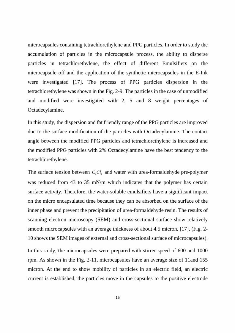
microcapsules containing tetrachlorethylene and PPG particles. In order to study the
accumulation of particles in the microcapsule process, the ability to disperse
particles in tetrachlorethylene, the effect of different Emulsifiers on the
microcapsule off and the application of the synthetic microcapsules in the E-Ink
were investigated [17]. The process of PPG particles dispersion in the
tetrachlorethylene was shown in the Fig. 2-9. The particles in the case of unmodified
and modified were investigated with 2, 5 and 8 weight percentages of
Octadecylamine.
In this study, the dispersion and fat friendly range of the PPG particles are improved
due to the surface modification of the particles with Octadecylamine. The contact
angle between the modified PPG particles and tetrachlorethylene is increased and
the modified PPG particles with 2% Octadecylamine have the best tendency to the
tetrachlorethylene.
The surface tension between 2 4C Cl and water with urea-formaldehyde pre-polymer
was reduced from 43 to 35 mN/m which indicates that the polymer has certain
surface activity. Therefore, the water-soluble emulsifiers have a significant impact
on the micro encapsulated time because they can be absorbed on the surface of the
inner phase and prevent the precipitation of urea-formaldehyde resin. The results of
scanning electron microscopy (SEM) and cross-sectional surface show relatively
smooth microcapsules with an average thickness of about 4.5 micron. [17]. (Fig. 2-
10 shows the SEM images of external and cross-sectional surface of microcapsules).
In this study, the microcapsules were prepared with stirrer speed of 600 and 1000
rpm. As shown in the Fig. 2-11, microcapsules have an average size of 11and 155
micron. At the end to show mobility of particles in an electric field, an electric
current is established, the particles move in the capsules to the positive electrode

16
with a response time of several hundred milliseconds and are inclined to the positive
electrode [17].
In a study by Yan Xin Hu et al (2012), the organic pigment of P.R.2 (F2R) was used
as colored electrophoretic particles (Fig. 2-12). Surface modification to enhance
surface charge and stability of the dispersions was carried out in an organic
environment. The result was that the addition of dispersing agents to the dielectric
environment alter the size and shape of the particles as well as intensify the electric
surface charge [57].
According to the results, SEM images, particles size distribution of raw material and
modified with ODA that is shown in Figure 2-13, particles size distribution was 100
to 1500 nm in the case of pre-modification while this extension in the modified
particles was reduced to 80 to 220 nm. In this study, the average size was 105 nm
and a very narrow distribution of dispersion index was 0.068 [57].
Various modifiers such as sodium dodecyl sulfate (SDS), Cetrimonium Bromide
(CTAB), CH-6 and Disperse 655 (D-655) were tested. According to the results and
Fig. 2-14, the best of them is commercial dispersant 655 (D-655). The sedimentation
rate of the prepared particles in the tetrachlorethylene was less than 5% in 12 days
[57].
In order to show good contrast in an electrophoretic display, the red particles are
used with white electrophoretic particles in which the response time is reported 200
milliseconds, respectively (Figure 2-15) [57].
Sun Wha Oh (2009) reported a communication that charged ink nano particles of the
three organic dyes are obtained through encapsulate of these three dyes with styrene
dispersions polymerization and 4-vinyl pyridine (poly (styrene-4 VP).

17
Poly Styrene polymer particles- 4 VP containing three acidic red 8, yellow 76 and
blue 25 eyes using two surfactants sodium dodecyl sulfate (SDS) were used as
anionic fertilizing agent and acetyl tri methyl ammonium bromide (CTAB) of the
cationic agent. It was shown that with increasing the concentration in both type of
the active surface from 1 to 5% by weight, the particles size was reduced from 1.5
micrometer to 800nm. Also, with increasing the concentration, the number of
effective charge sites is increased on the ink particles that leads to increase the
particle electric mobility. Figure 2-16 shows the electric movement rate of positively
charged particles of three different dyes [43].
Xianwei Meng et al (2010) synthesized the spherical Carbon–Iron Oxide
Microspheres’ Black Pigments (CIOMBs). This black pigment was prepared
through the Pyrolysis of aqueous solutions ultrasonic spray containing ferrous
chloride ( 2FeCl ) and glucose. Figure 2-17 shows the image of synthesized pigment
particles in the different concentrations of 2FeCl . It was observed that with increasing
2FeCl , the surface of particles becomes rough due to the particles oxidation through
the iron ion [58].
Since the poor dispersion of electrophoretic particles limits the applications in the
EPDs, the spherical carbon particles obtained by dehydration of the polysaccharides
water soluble under hydrothermal conditions showed an excellent ability of
dispersion. Based on Figure 2-18, many functional groups on the surface CIOMBs
(such as: OH, COH, CH2, etc.) leads to excellent dispersion in different solvents. So
CIOMBs in polar solvents (such as water, methanol and ethanol) and non-polar
solvents such as tetra chlorethylene are dispersed as well [58].
Despite extensive studies, preparation of tri-color electrophoretic particles RGB with
high surface charge, very good dispersion stability and good light stability are also

18
required for Chromatic Electrophoretic Display (CEPD). Wenlong Qin et al (2012)
modify the three-colored pigments of RGB through the in situ polymerization,
styrene-acrylate copolymer solution. The chemical structure of three red, yellow and
green pigments are shown in Figure 2-19 [59].
In this study, different acrylates containing Stearyl Methacrylate (SMA), dimethyl
amino ethyl Meta acrylate (DMA) and ethyl glycol di Meta acrylate (EGDMA) were
used as monomer (Fig. 2-20).
In this study, Ethylene Glycol Dimethacrylate (EGDMA) causes the crossling
copolymer on the pigment surface. This leads to prevent the accumulation of
particles and their stability in the tetrachlorethylene nonpolar environment (TCE)
that is one of the key parameters in EPDs. Figure 2-21 shows the sustainability
comparison of pigments suspensions with/ without surface modifiers after 24 h in
TCE [59].
It was shown that small amounts of EGDMA leads to increase the zeta potential and
mobility of modified colored particles with P (SMA-DMA-St) and also the reduction
of average size of the particles according to the table 2-1 is 1.2 times the original
size [59].
Also in this study, response time of pigments in CEPD sample device made by this
group was reported about 0.7 ~ 1 which needs to be further improved. In addition,
RGB E-Ink light stability is very important in CEPD performance.
In order to evaluate this parameter, EPD prototype was exposed to the Xenon lamp
radiation (500W), 14 times the light intensity of sunlight at noon. It is concluded that
after 36 hours exposure to the light, the RGB reflection remains stable that is desired
for stability of CEPD equipment performance [59].

19
Chunli Yang et al (2014) modify the titanium dioxide particles with Vinyl
Triethoxysilane (VTES) with Sol-Gel method through flow groups’ graft on the 2TiO
particles surface. 2TiO Particles have excellent image in the dark surroundings for
contrast and are widely used as white electrophoretic particles in the manufacture of
E-Ink. However, since this particle has high density, van der Waals attraction
overcomes and leads to aggregation, quick sedimentation and slow response to the
electric field.
Therefore, extensive research has been done on surface modification. In this study,
the results of the whole FTIR are confirmed the new peaks in 1560,670cm−
wavelengths due to the stretching vibrations and also two peaks with 11.020,1.120cm−
wavelengths which represents the stretching vibrations of Si-O bonds in VTES [60].
So, it was shown that VTES was grafted as well on the 2TiO surface (Fig.2-22).
Modified particles size is reported in the range of 100-200 nm with very narrow
distribution. Figure 2-23 shows the stability characteristics of dispersion and
suspension before and after the nanoparticles surface modification [60].
In a study Hongli Liu and his colleagues presented the electrophoretic microcapsules
using Isopar L as dispersion medium with mass method between gelatin and acacia
that its features are non-toxic, low concentration of aromatics and low evaporation.
The effect of weight ratio of capsule material to the nuclear material, PH value,
dispersion time and speed were investigated on the microcapsules properties. In this
study, the ratio of capsule material to the nuclear material is 1:4 and capsules walls
with PH=8.5 in temperature of 045 C and dispersion time and speed are reported 20
min and 800 mpr, respectively. Figure 2-24 shows that the higher the ratio of nuclear
material to the capsule material, the lower the particles size followed by the increase

20
of microcapsules efficiency up to 70%. Here, the best picture with the size of 30 to
60 micrometer have been reported [61].
Also, with increasing agitation speed, the particle size is reduced (Figure 2-25).
Figure 2-26 shows that in PH=8.5, the microcapsule efficiency is 83.88%. The low
efficiency in low PH implies that some of the amino groups of gelatin still exists as3NH + . Hence, it cannot be cross link with Formyl group while some parts of gelatin
are destroyed in high PH [61].
Clock display panels made from microcapsules in electric field with direct current
of 5-volt show clear images of white context with black background and vice versa
(Figure 2-27) [61].
Some of the problems of the two-phase microcapsules are stability and respond to
an electric field, prevent the extruded nuclear material as egression from oil phase
to the aqueous phase in the encapsulation process and particles absorption on the
inner surfaces of capsule shell.
In a study published in 2008, the effect of polyethylene membrane on the Benzidine
Yellow Pigment was studied which aims at its Pregnant and prevent the
accumulation of yellow pigment particles due to the creation of a spatial barrier
around it. According to the results of investigating the particles size and their
response behavior in an electric field, the electric movement of these particles are
modified and finally dispersed urea-formaldehyde microcapsules in cyclohexane as
E-Ink are reported 10 times more than unmodified particles [24].
The application of nanospheres is in painting, ink, food, electronic displays, textile
and medicine. Kuanjun Fang et al (2014) introduced an easy method for preparation
of colored poly (styrene-acrylic) nanospheres. This method was performed easily in
21
contrast to previous methods in which the preparation of uniform colored
nanospheres with high color purity was very difficult.
In this study, the Emulsifier-Free Emulsion Polymerization was performed to
synthesize copolymer spherical nanoparticles (AA-St), so that the effect of the active
surface was removed. Spherical nanoparticles dispersions were prepared with three
solution disperse dyes including blue 56, red 60 and yellow 64, so that each of the
dyes are gradually entered to the copolymer spherical nanoparticles (AA-St) due to
the heat and then fixed dyes in the spherical nanoparticles are obtained with
increasing heat and sedimentation, washing and dying. The process is shown in the
Fig. 2-28 [19].
According to the images obtained by transmission electron microscopy, the average
size of spherical nanoparticles after dyeing for each three dye is 23nm [19].
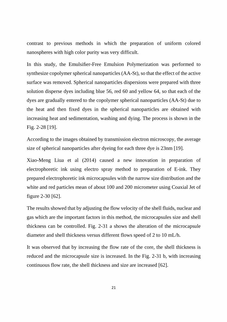
Xiao-Meng Liua et al (2014) caused a new innovation in preparation of
electrophoretic ink using electro spray method to preparation of E-ink. They
prepared electrophoretic ink microcapsules with the narrow size distribution and the
white and red particles mean of about 100 and 200 micrometer using Coaxial Jet of
figure 2-30 [62].
The results showed that by adjusting the flow velocity of the shell fluids, nuclear and
gas which are the important factors in this method, the microcapsules size and shell
thickness can be controlled. Fig. 2-31 a shows the alteration of the microcapsule
diameter and shell thickness versus different flows speed of 2 to 10 mL/h.
It was observed that by increasing the flow rate of the core, the shell thickness is
reduced and the microcapsule size is increased. In the Fig. 2-31 b, with increasing
continuous flow rate, the shell thickness and size are increased [62].

22
In this study, orthogonal test was used through three factors and three orthogonal
experiments levels. Three factors of core flow rate, shell and gas are separately used
in three different levels. In this study the optimum values are reported 4,6,25 /ml h
and coating Ratio was 90%. Fig. 2-32 shows the charged particle movement of red
pigment in the electric field [62].