electronic - world radio history
TRANSCRIPT
I
I r
ELECTRONICTECHNICIAN / DEALERWORLD'S LARGEST TV -RADIO SERVICE & SALES CIRCULATION
C.
F TEKLAB REPORT ON CRAIG 6304
CURVE TRACER TROUBLESHOOTING
STEREO SERVICING PART TWO
APRIL 1970 r] A HARCOURT, BRACE & WORLD PUBLICATION

The first and only solid-statetest equipmentguaranteed for 5years.
Now EICO, because of its emphasis on re-liability in engineering and manufacture, offersthe industry this breakthrough.
EICO's new line of solid-state test equipmentcomes with an unprecedented 5 -year guaran-tee of performance and workmanship. (Send
for full details of this EICO 5 -year GUARANTEEon factory -assembled instruments.)
Additional advanced features include: newfunctional design, new color -coordinated es-thetics, new PC construction, new easier -to -build kit designs.
New EICO Solid -State Test EquipmentIii'- PI
379
EICO 240 Solid -State FET-VOM $59.95 kit, $79.95 wired.One all-purpose DC/AC OHMS Uniprobe®. Reads 0.01V to 1 KV(to 30 KV with optional HVP probe). 7 non -skip ranges. in 10 dBsteps. AC or battery operated. RMS & DCV: 0-1, 3. 10, 30, 100, 3001000V P -P ACV: 0-2.8, 8.5, 28. 85, 280, 850, 2800V. Input Z: DC,11 M; AC, 1 Me. Response 25 Hz to 2 MHz (to 250 MHz with op-tional RF probe). Ohmmeter reads 0.2 to 1 Me in 7 ranges. 41/2"200 r4A movement. HWD: 53/4". 5". 6 lbs.
EICO 242 Solid -State FET-TVOM $69.95 kit, $94.50 wired.All the versatility of the EICO 240 plus: AC/DC Milliammeter, 1 mato 1000 ma in 7 non -skip ranges; single all-purpose DC/AC-Ohms- MA Uniprobe®: and large 61/2" 200 µA meter movement
EICO 150 Solid -State Signal Tracer $49.95 kit, $69.95 wired.Multi -purpose troubleshooter for TV/FM/AM & Audio Equipment.Independent RF Audio inputs. Speaker and meter output indicators.400 mW continuous power output. Substitution amplifier, outputtransformer. speaker. Input for rated output: 1 mV RF. 63 mV audio.
New EICO High Performance Instruments
385
""fteervr
465
VSEMNII6a
lirt(114111025 633
EICO 385 -- Solid -State Portable Color Generator $79.95 Kit, $109.95 Wired.EICO 465 - Wideband Vectorscope/Oscilloscope $179.95 Kit, $249.95 Wired.EICO 1025 - Solid -State Power Supply $34.95 Kit, $49.95 Wired.EICO 443 - Semiconductor Curve Tracer $79.95 Kit, $119.95 Wired.EICO 633 -- CRT Tester & Rejuvenator $79.95 Kit, $119.95 Wired.EICO 635 -- Portable Tube Tester $44.95 Kit, $69.95 Wired.
330
Hum 60 dB below 400 mW, 105-132 VAC, 50/60 Hz, 5VA. HWD:71/2", 81/2", 5". 6 lbs.
EICO 330 Solid -State RF Signal Generator.$59.95 kit, $84.50 wired.5 fundamental bands 100 kHz to 54 MHz. Vernier control 0-100%.Output 300.000 uV into 50 -Ohm load. External signal modulationor internal 400 Hz, 0 to 100%. 105-132 VAC. 50/60 Hz. 1.7 VA.HWD: 71/2". 81/2", 5". 5 lbs.
EICO 379 Solid -State Sine/ Square Wave Generator.$69.95 kit, $94.50 wired.5 si wave and 4 square wave bands. Low distortion Sultzer feed-back F ET c.rcuit. Sine: 20 Hz to 2 MHz; 0-7.5V rms into hi -Z, 0-6.5Vinto 600 ohms Max. distortion 0.25%. Square: 20 Hz to 200 kHz:0-10V p -p into hi -Z, pos. direction, zero ground. Rise time at 20kHz less than 0.1 12 sec. 105-132 VAC, 50/60 Hz, 10VA. HWD: 71/2",81/2", 81/2". 9 lbs
New EICO Probes for the ProsHi -Voltage Probe HVP-5. Wired $19.95.
t;venient t' *; Barrie, sections isolate HV do from handle andler. M?ast, -; KV Lightweight, cortnna-
Solid-State Signal Injector Probe PSI -1, Kit $5.95. Wired $9.95.Pen -size. 1-cunce, self -powered signal generator I r e JenCy range from 1kHz to30MHz. with harmonics. Clip it to your pocket - ideal for signal tracing in thefield
Solid -State Signal Tracer Probe PST -2, Kit $19.95, Wired $29.95.Flashlight -size. 2.2oz, self -powered. Hi -gain amplifier. 50Hz to 200MHz withdemod tip. Input Z: 350011. 351(11, 350K11, Output: 0.3 p -p volts. Noise -45dB.Distortion <5% Complete with earphone. an probe tips. AA battery, pocket clip.
11=211
HVP-5
-AMPST -2
17E/CO
P5I-1
SEND FREE 1970 CATALOG
Name
I Address
City State 2,p
EICO Electronic Instrument Co., Inc.283 Malta Street. Brooklyn N V 11207EICO Canada Ltd.20 MIIIWICk Dr,VO Weston. Ont.r10
. . for more details circle 112 on Reader Service Card
ELECTRONICTECHNICIAN / DEALER
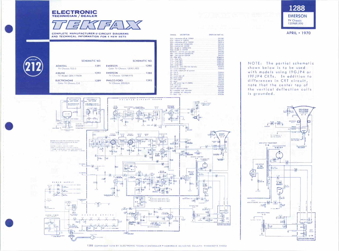
COMPLETE MANUFACTURERS' CIRCUIT DIAGRAMSAND TECHNICAL INFORMATION FOR 6 NEW SETS
SCHEMATIC NO. SCHEMATIC NO.
ADMIRAL 1291 EMERSON 1290TV Chassis TG2-2 Color TV Chassis 120921,923
AIRLINE 1292 EMERSON 1288TV Model GEN-11960A TV Chassis 120969,970
ELECTROHOME 1289 PH I LCO-FORD 1293Color TV Chassis C-8
1.111KUNP TUNER
l111 IWW0.004
,ver asi.v.ewmaas
ilOACal r0 C1 II q
4-1911 MOR ID
.... InT.v0VOInNwe
pawn. worn., NNE TUNER
1111 MRS r Y14 OCRS& *ea. os
WOO
VIK ea OKA taW.sPil Coa011.r...0 Lov. 7usus 3331743 wo31116, 3ve 33
0,0111141.1 511.040 1110,011. WOO, 0UMW. a? [0.001, 0431 ,OV my. SI 01,101e
Ivy (VW 0000v1 ,W10 10
COVEN SUPPLY
CLOCK ....TIMER
.
v AC 40 Cr%
TV Chassis 20S32/A
SYMBOL DESCRIPTION EMERSON PART NO
R29 - volurne/on-off ch 120969 391080R29 - volume ch 120970 391079R29 - volume/on-off ch 120959 390814R30.- contrast ch 120969,970 391048R30 -contrast ch 120959 391002R32 - bright ch 120969,970 391046R32 - bright ch 120959 391001R37A.B.0 - vert Lin vert site AGC 391082R80- vert hold ch 120969.970 391047R80- vert hold ch 120959 391000C2- 22pf NPO 928824AC12 -22p1 NPO 928824XC14 - 5.6pf NPO 928817XC17 - 4.7pf NPO 9288I6XC20 - 6.8pf NPO 928818XC56A.B.C.0 250250-100-50/160v 925714T1 - sound interstoge 720513T2 -audio output port of speakerT3- 1st IF 72045414 -2nd IF 72045515 -sound take -oft 720512T6- honz output 738210T7-vert output 738193L2 quad 72040414 -self sound trap 41.25MHz 720453S12 -horiz osc 716165114 -del yoke 708532AL16,17 -filament choke 705031Ni -couplate. sync separator 923059N2 -Luuplate vert integrator 9231 S9Fl -fuse. I 2a 808236
P R I NT ED CIRCUIT
I VIA.1 UP Vvw velentwa vv.ocv,ro.'LINE r or 1,1 40111s40111/1
.11 ,,-- ow
sort ENT T
TRIMS
3-1.
V-1141.0AN. vvv.v rt
1-4 II1
,
te
1..)/
N
4S 7v -ii RnwA
.171./131.1ITCANICUS
I
AuOremi 0,4 qvT
7th.-57-
0733 vOLL43 VAR." WI 1. 43
NVOLTSE WIRT RI v MOLDVOLT611/4110n aitm MOLD
=ow=;4d ti4
3 SI
417" NY, ImmYlit 10010
mr wee.,V PR
J 1
421 Tot=.:f
o4,6'°001(1 4-
C
rt
144*I.. I.
103
VtiV, ty.VVVVIWill
T I
lift
L 14
DEFLECTION YON/
1288EMERSONTV Chassis
120969,970
APRIL 1970
NOTE: The partial schematicshown below is to be usedwith models using I9GJP4 orI9FJP4 CRTs. In addition todifferences in CRT circuit,note that the center tap ofthe vertical deflection coilsis grounded.
R - 33 R-34
4--t0K 4 7 0 11747
BOOST
RID uMo
CENTERINGASS
19GJP41A)19FJP41A)PICTURE rust i
If 7
2131.1
OR10131
0 I I
r LOW
TO TERI/111C.ON PC BOARD
NON OUTPUT TRANSFORMER
T.61.1013 VOLT RECTIFIER
V710 IIK
HO. OUTPUT
V9A36107
SoC60 5v R 65
C-4.
4 501 1100ST SOURCE vl - 17
C -439=I -6003,
VIE RT OUTPUT TRANS
T7
T o or 7 V
033
0061PfliV-98
3911E7
C -71
t-600
30V
11A/ ON
C-73
R7NOR C01.
jj.2
1 Viol
1
1
DEFLECTION YOKE
VERTCOILS
1.14
1288 COPYRIGHT 1970 BY ELECTRONIC TECHNICIAN/DEALER HARBRACE BUILDING, DULUTH. MINNESOTA 55802

1289
42 227g, N46415;OK (. VO TO 6.12J
i E201V0201155 --46 r16v
....-
.---.-...5:'I
'"F -1Co' .°.' 4'.
51
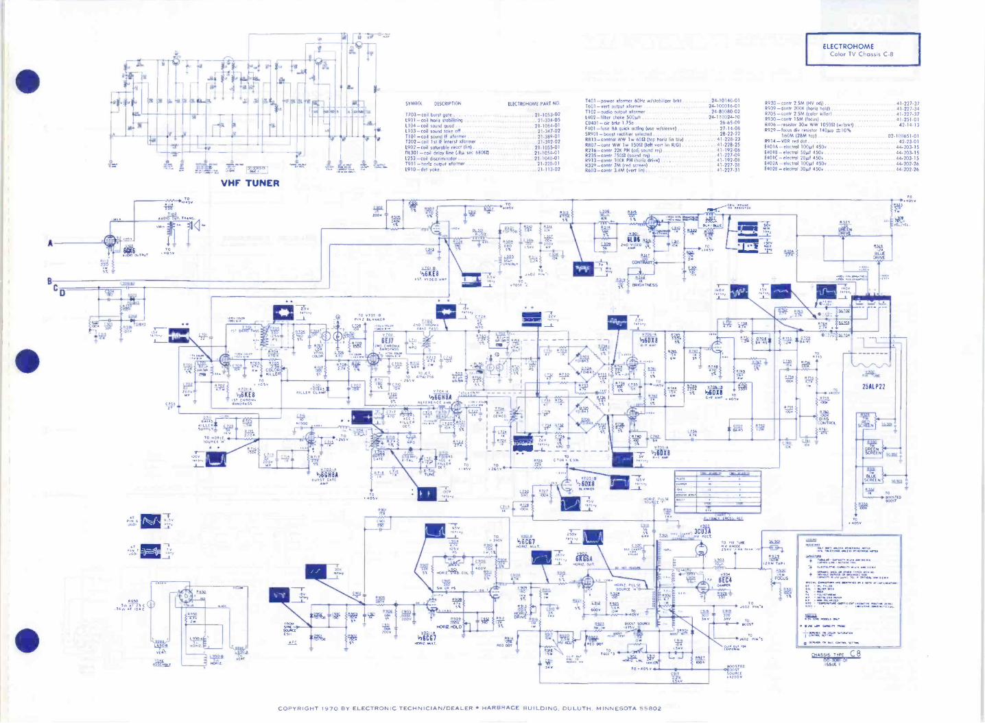
ELECTRO-HOME
Color TVChassis C-8
TABLE Of ..:04NEC TONS
0 00GN54.40
5 50 v
::.AL4,Nu. LIME10. vv.7 17411S0PRNmoG« vegf 60541704u.47 13740506TC.11.401G voLuaaf TCREGULATOA aop,a,
,1 NAT LACo4 MCP LNE
vOLLAIE LP4
00000 "I 0000000000
PI
Po 00.44CS COV000 VP? TON44. C.4.551,
ELECTRONIC 777-WL7=TECHNICIAN /DEALER
APRIL 1970COMPLETE MANUFACTURERS' CIRCUIT DIAGRAMSAND TECHNICAL INFORMATION FOR 6 NEW SETS
ETO Port 7 Of 0205
BF- 0045.)5151, .
- -
F 1.231olvLoT
C 01145.75NA,
6(7104 voEr 0, S0,10 STATE OE 010E5
75 (.;I" "
SE 5006
IAlec T.1_
0673% 2r,4201
U2OK
oPl; 951,411
0203IC1
.0
'T
T .EGL T
1*0_,
YreraCASC ANIMATOR 251
COIL 1
57.'x, r'
Roo-
.t ,90141.AA. STAGE CON45.7561mo
CJV
I-MED
AFT
T20;1177116.GM CON.4246,
A' NULL
1.W92 2201
W-vALAC TOR \TUNER
5 5,
220'
0251
11.1
IL ISB6
hssS20
NO0
TOB 1251
Aggc;640
5% 5%
,TIMM I
..0 260
pal- -
5t;44
220.SE5050 MOOS
56+ , 10
0259
024.11.7 lir
ISM .11na-3
1% (24.. 0c2b2
0201
T202
Ii
$ 2 2 5
22 02 4E10-
TUNER_C 2
Ise Ts3
UHFVARACTER
CONvE.TL.
120
°-4-4.6%
SUMS;O. 54/
eft
seet -
Ia
;0.709,1 C.471054901
" 41T 0:44407E0
r.GULATO.40a
I oNT&LOC
I 2c0:,
2119511
1
14.01cm, NJ 0.L03
4201 EIC1T101
6. o.
NUZE.E. GA
;or6.7 ,TE
TO MYRA....SOLACE Ca
CC.I.ONTE 04:4E0XT. Co405 a 1 05
0511
.A.A kieRE -AGO
_ SENSITIVITY
5%
224Tio
.22
5% (EN
O 202
,DE M)ri-
kit
ZOLIEIC110NPSISKI .5
GC 0
(0,106
C4Q,
0512
Iyur ttr74 I "LI
v., 11LI
(0-a500n LOv
70TITGy2oslis
v.40513
26951
A515
2
TO-r .265 vs0aalii3314 SEP.10.
;00.SEC1;
ts5ro
2.21
0:007.0
P5224-77
5.4051
s- v
6.2650
,0
.5
*202
2ND,'
0051151E SOI.00E OE CO..011T4TO NOISE GATE
ilk5to
89
TO1450
.5.0 -MI
TO A
6E173.0
OPT
.500
11224.5040.-
LQi =
i10' II
720444.0.44,
Uj.1011
I.5AV 5%4.S
65045%
roROOST
1.110PIO
TONE
7 ST;$4
5%
09Eli22,24
rLILI 1.
10 4 - 4,Pill
. 1.112
1,.911; I A fee_
(114
41
IR
c c.UP.
5%5% 3r, 107
:00v ( v6014*2 TO
4145V60-TIA
505.0 OE T.
s `-125236 .N .K.I
0. I
C2,274 1205RAI!,
1.1..r. .0.! '7
5% . ill ,..--sa--4 Wiiii5 LW
C 222 C "; 54,. --m , -L- - - -', . . ,
A 235To
i f LIU) I
011 WO
, ,T(.5 , ,4,2 ! 4;1% 6045.6 ao'1 r 7 TRAP NULL .T(65 .
C501;00
o
14LIvOLLNIE
T
-0010,
4050OURCE
---attrKE1464. "1";450v jr 4500
-520V:Cf
.gt
c1.92 DION640 i To7o002551 o6v
o±g.17424764
145V50u.CE
2 v SGLIACE
Qv SOLP.CE
0603 A606
C 602.6331F
4000 610
1210
CEOS
600v
.604
"vEAT.LIN TO
0.4050
2S,W .722V:6000 5%.0%
0608 9OOP 0062
IRV
afivoio
601.0air/2( ITT OUT
OOVERT'G HEIGHT
ISOAGHT 140NZLINES BLuE
. 5.2,1Vs.1( ,
*2
a.§2 0104OOR
""°0 T5e02
A 605
L1 rT SUE
-PM
E 601
50 TO
1500 .05
1 -
;HOW
11
TO JCT. 0.0 a C 914;
C C 9,6
u
.32,034
A5 v
51241111
PEAK RASELECToc,SWITCH
a
G.. /AL.
TOP a DOT TONopo T MAAS
A
'OP 14611001T TomPIN PHASE
TO AT OE1902 a 1.e26
-r260! ov,
PINAT 4 RI -T,
2601J-
TP;o4 5
760; 9c./._L
C 004
4000
be
LuNOE LINDA'SIto,00
2000"40004
0 004YERT To,,00
LINES RIG
TOP 401512LiNESELIE
E0qTLINES /G
60
V;14.1181 T3P4E
reisiEatiCI 495E0,704
130;.;.71.71GEKE
1289 COPYRIGHT 1970 BY ELECTRONIC TECHNICIAN/DEALER HARBRACE BUILDING. DULUTH. M I NNESOTA 55802

1291ADMIRALTV Chassis TG2-2
APRIL 1970
SYMBOL DESCRIPTION
ELECTRONIC7 r -w=i4a "JrTECHNICIAN /
COMPLETE MANUFACTURERS' CIRCUIT DIAGRAMSAND TECHNICAL INFORMATION FOR 6 NEW SETS
ADMIRAL PART NO
R111 -10K, 1w 60814-103R208- IM, vol coot w/sw 75C 120-1R320-308. contrast cont 75(121-3R322 - 100K, bright cont 75C121.2R402A - yen lin cont. dual 75(95-6R4028- height cont. duol 75(95-6R421 - IM, therm 60A64-1R422 - 1.2M, vert hold coot 75C121-18502-5.512, fuse type 61(48-IC135 -39pf, 5%. NPO, cer disc 65010-347C327 - 6.8pf. '4%, 500v. NPO. cer disc 65D10-102C406- 330pf, 10%. 5kv, cer disc 65D10-266
re fulls Pio. ft 0Atti 1 105OW IS ofz.,0 /111 1501' Of Wit t(Alffr Ilell C/ 55115,0,15.10112(5
ffootcfm 110,1I10/(I/ riff/ June,:
51034.01
1111400012110 10 00011
1111140 I1141110
Or A Or WM II( 1411Or 155(1151
00102
r. *2-n
Joe, :1'4>,rY/
I
,
11.1
LC
-4010
$1911L
L _J
14103
Si A11111100
L103, 0111 0104
2,.1-C104:
1102i
Clot'21
,os!
Tim -1
L105
401
100?001104SL( /SST
1115410(0
L04
1000
C430 - Spf, 10%, 1kv, N750, cer disc 65010.345C504A -1504f, 165v. elect 67015-393C5048 150W. I500, elect 67015-393C504C 200,1f, 150v, elect 67015-393L202 quod coil 72(132-77L401 - Mara lock coil 94017-17T201 oudio output )(former 79C81-231303 -sound takeoff dormer 72(185.5T401 - veil output 'dormer 790100-177402 -del yoke ass'y 70001089-2T403 -lush: output 'former 79D117.1CR401 - horiz phase det 9385-9
tuner UHF" 94E361-1tuner VHF 941360-I
VHF TUNERC1/2
51C -LH1 PLO( 1011
'40
3HA5VII 10viol
1101
(10101 SO L2111
11011(
00.1i1
C110
4 I
0
7113
94C360.11101
I/25GS703 1111E1v1020 L122
4011
1000
TOM ill tutu
TP024
1-100
1101 104 4111221 It
11
101 0,,
It1112
r24.._,.....____,, EIS Ill If 111 SAW WS ,
SIRIM
,11; 1L3
EI f1
8.4711/.0.111311111
.1-- L132 11131
1-130000 000-I
30
VII CSC0102
0131
144
la
2I
,t143
0011
f00/11 C;CAM
c,04.
OI
tc-±
I
3HA5
4I
VHF OSC.
& MIXER
4VHF
RF AMP _
SOUND DE!1 1
0& SOUND
OUTPUT
17BF11
12
0
0
UHF MIXER
93A59-1UIHf OSC REPLACE ONLY WITH
57821-5 TYPE ORIGINALLY USED
0
(-Fel
93C12-3SILICON RECT
f41-1
VIDEO AMP &
SOUND IF
ACC &
SYNC
SEP
01N87AVIDEO
--)DET
93B5-9HORIZ
PHASE DET
4+4
PICTURE
TUBE
HORIZ
12
HORIZ OUTPUT
& DAMPER
VERT OSC &
VERT OUTPUT 17J18
TO SIMPLIFY NEATER STRING DIAGRAM, TUBE SOCKET PIN NUMBERS ARE NOT SHORN IN ACTUAL LOCATIONS.
I/28JV8S0001140
V S 21rir
L302 -4.1.301-1=- If
1301
Sl 0"W
1.301 _.-002 i130211 1300
.1211.41.A1110
PRECISION WIRED SYSTEM
L2018
714E417 -IV217BF 11
!..02111
-C213
TV,(r0.II12200-r_
00101
, .,.,?
211f_.011000,Ilo
pp Ill.IOW 01
0201It
".' L 202
'
8BM111/1v30,4
elf,
o
130311
1,,..11°.0
T30. Ir515 1101
331
11 -/201 0 004 II II" 'ill 301
1111
IC101
20130 ' 5001
I C110
UHF TUNER 94C361.1.141132,L544-1f art/
010041
-711------1 - ---rult
1.152
.1.511 151
10
93A159-1 11
XVI, gi" 01
.
1I!NM- - - - - - A H - - - --- ---I-1
,..1 1100
,fMMOm1=1=1112(40,, T DA 1SC 1111C1141sIl ,
I CIS2
'Iv t ) 57821-5_Lou
000
0131
Tea
$113j L21 L154
1154220
UHF OSC
01St
511 f M II0 115/ 11/10 et /I
mow, ow(5155/S mu,
MI off WWII,* IMMO, flarl0 x11/11/ 1111 rift Wm 5(//MI( if (1511/15
0111(5 la *VII filo tInce ft/ 0101(5Il ItclIM11.081(15 1111114( III/(1115IC 111111(5 ',Wolff Al ',Or At LW, 00 310111.III (WWI I II/ro1l/15 11/I MOW Ills fro
O
11'III'
ACC""
1404 1105
1.210 5.11410
2101
1411
0.
135
6GH8A.50 SYNC
*1.V4011, V40,11
'I'lid, 1441
011
II_040.111
33GY7
OFF -ON
SWITCH
1200C
AIDE PIN OF
POLARIZED RUC-.
Ti93C8 -I
ll00, IIII 10 (3131111 C115II4 1101
130242102III- - - - L305 130/1
V217 B F11SO110 01I011
02010
11242101111
1311
210
1/28JV801000 11?
v9024
221
HO C405
1101Tzoo
1101111
LI
JP'
Ill
}Ills 105
111 111
14
1/2,vg 8v.02.;
1111
TSt
III
S.
371071-C2
Of I11.4901 MI SWIM1.-1"9
L119
01I I'M SITS S151(5 -100
rilotiO 4.... :01.17.1.1;i0i flaSHS111
0401 0302
110
702 1 0503114'.4i1r 114r
"001 130100 0 0 0
1012' 40/C IN 51(1(1"Ulf CM IOW/110554151 C0001115 10MIRK Of ItOrIC fatf
0
404 0403 0301
102_ILI 51
93852-184411 PLAY
moo(CR502
O
00v201
c3i5ill
TVA'
1sisal 1.1502 LA23 -
050 75501
If titlf 110INV AC Tig -
0-10 S111101111 V 1111
1542
5.501101111
9385-9NOM 114431 011
CR401
:IL 4N'_L
1.70
l(1;07 111Ifs001
.0211111111
1411
3101 _ _ _ _
11.0211 ' 5110
HEIGHT -1-
S.3.10
1.1,Q11110114101
He
I
!Olt,91=
r'1:1 C1;7,371:IA3 it1.9
-I-I
I' 0111 C III C311
L309
12101
2111VIII
017CUMI OM III/COI
p$0:- 1/217,1Z 80(11 401101
v4020CIll
03310,151i
041(0,,,i.' Cooli
11,,.. 1101 UZI,,i It 111
IfC111 .
Illr
HORIZ.LOCK
1101
.7.
140-I-
1444
0422
040010%
Ill
NO
8FQ7wow. osc
Dry
III
0421
loll 011
TV I
1.01:0,
Ip
C1.20' 15%
, 010
111
100141,7000421
I MC
fr-g
o.0(11:1s...2 o0(11.,:1911
33GY7
107 ,,;cp
'":415.1
a"
VAX"'
Iii1
mmo
19t {401
111.
\44511
93852.1 -0--. ", 11"S11101 10111i1/ I 001
PI ,.., 'lirc501 150P 0
041 of 100 5. c2
..j e10 91 110'1
13191 I)041[5,14t
ISM COW1151 MI 1511
50, /NI
!lir 145S
PIAUI offf fIll
1001
0131I0/1111
NOVO/1kt
0
IP II kW orNMI
Vj00202
01000 110
00201WW1
3
20(
WM MIS Off Off Man,'n 1117KWASC(111( 'MAC( off,
SW Mg 15 0/l(/IllMAW 11111 00 WPM
IMc 0000 /MAW
I
11
1121
.1 I$11112111
$ 1401
on 0 En 0
1111
50,
CONTRAST
111Mi 111911,
1-11T 111 01
VERT.LIN.
"27 VERT.Rio HOLD
40
1
1141not
9
±2011Tool 511
I. Hoy 11
0113
1IIrIr
111
1111
1,101..111
1BC2
0
040
0211110%
117714111-.4
101220
11 V 1E0110V405 111100 NON 7402
II
NIL1144 100
1 KE
1111 `5114 I
1 j
11601
1
.
1,001 1.11
0301
103-
Go,
BRIGHT-NESS
Mfg( C111100 PQM ProMIMS III PolitlfIrtfOrt f0 011I1o1 fhtft00,7ofaCS (00.1111/SOU
9TP49ADP4
ill
5
JL4041
_A_
1. ...1
I
T:frati
0
40 oll .11 01(
1111- rli11111
00 fOr MS01(
V2
33GY7iDiet,
L403
I
RUN CHANGESSport OlDrOdyttion.
1291 COPYRIGHT 1970 BY ELECTRONIC TECHNICIAN/DEALER HARBRACE BUILDING. DULUTH, MINNESOTA 55802
44/
=ID
R 116500 55COLOR
Z TO8,syEyo MS/
OR TO
09194.074 Wu Icy
oC Ka
,1,e4170 2W nO V
+150 0 270 V
OP0
CL5Q1
AEC!
`,iS3 IV-VOIA IIONSA
ACC MAT
50-1100 SUPPLYR 301
I302
20K
,Afic
N---- 1ST CNROMA AMP ,-302
fiat1.301NROMA
TAM Of
'4130031157
hs.r3C,cnOr( um)
T-301 V301A 6011111111 7.302CNROM 290 CEEROMA .2ND -.14044
BANDPASS 8.313 AMP TRNSTRANS
I 3"§nD 7'
C --31I 1400 I
3 1330 C-305 -r 3
611
11; C i8s"*":?""10.3V 9
K
1000
IV 1130411w..R5609 t#2181 iv
01 +2t00 ACC Df TICTORC 302 VO010 ._
I
J
X-505 5.303 CIM* R590-o+150014506tea I% 4--401F-
s150041'
1151C MROMA
14*:.404
41:61(5111EG 1GR-509 R-311
C 31(4G C,019)7
li2
C
D
6-123106
TINT
01.1101DELAY LINE
R-124100
ssALIAL
51cKow 34471
CP `fl
V
1I
C 1090
.4_9. 5014150 v
V4110111110NSABURST AMP
260V
7.303 Y-301BURST TR 358 MC
OTAL
2
335270
6.337270
1.2,4V
10.000
t14336470R 338
120K
sC 32422
C
18.3452211
-62078
*"-3' ACT 5011_2701C. (Ho or Wmo Still
11-304A-111CINISA356 MC CISL
215V
4
I. 30747711
+2707
(i,(U
V -303A -6014111A
pi,ds M2001..,,
2507
"i361g16
027 2000-10 2
6-434t tOOlg
1
+ 2 0 VTr 65-63g
OMR 847o) 7
12'46 .-1T10-233IC:3011.0370ot20(
.4340t 'so 337*13 0T - 304
3 58 kic TRANS C
5.54*I i+-2V
OC 351 7
I4 700?
1, ,1.0 L._ _1500
11.346 5, 335345 64° ° I o.000
6 - 0 4 yM47KIWR 344474 WC 3320C 333 P'
12 10.000 +2700 6611
VERT BLANK6.305
1c200v WY*
,000 2 1,s-i. 2200
359 L.311 W----4C 347
I NO 2 00 -I.5V
C 343500 R361
398SC100-546
6306, 6-307NOR PmSE DET
V-5051 IDONIIIA+0101ZONTAL 0:C
V40111OLDIVIDEO OUTPUT
C - 349680
II, 364270
1 220V
2157
T*%9331;10002*
+2700
R-3469104
11 3701000
F
+270VC-557 R 382 C 362 R 385
330
- * 13-1.
12 i',812car
I
/ 'PlYe 7r"--- --1 R- 5"/M 2208'
5*36R 3111 t c 389*
C
42 _oo
2 v ,1
1000,/piot
-4 R-361347611
C 361 3N-313347 7 a 0 6800-21,
C
0 50
185V
T P
0 IfcNbe
9.391226 19
3 2700
24V -I1C 365470 ?0
2700116112
11
6-395 31- 397180 27011
C-369 o- 1000
1:7309.6t SC03;0
393 500
?L JUSTR -394 C 371330 10,000i
+270 V
R. 367686
IR 398
ffeK
C 37214700
SR -399 7100
R 401100
x305
100I 1.0612 NO10
TO PC 200.F56
1.101101FLICTION YOKENOR 2 COILS
iogo
V10140K66
.0F1 OUTPUT
-8002250 5
3P 127-47
MV PuLSI8(5
C 3731000
12
C 338
03001150041010
SITS1
0
PC -300CHRONIA a DEFLECTION BOARD
V3051111010A11 M P
90V IR 327
TICi 3113
123.1%
R 323 # 324120 A 'MEG
°3504' C 11119
62070 1-4000
C- 201 100
+270v
r)03Ot
12YG
4-1C321
04712.250v
V-106PICTURE TuBE
79 1100
SG 301
R 332tI M1G
-62. 2. 2 70V
L 333 0lFek.230205 641VO
R-26 R 329 63316800 398-4M
5w -
13.6 0
B LUE DRIVE
V.30411111614111A81.N#10
70V
4 I 73V L
-10011
R 348220"
2g:4303V:461
i sore swi.. 21000 70
-10--±' -
2 DEMOD
c.N51Ci
.,)..5.4,
"im_i_317Gsyv:
.E.
/C -35:i.
T RP36e /r51119C.150505
-- + I 50 Vis 7 2.75V
V301 11 -1101111AVINT 05C
R 4021,330P, 0 .375
6226001,
C2Kt C,.4,76:* I"at"
1750
-45V 7
IIONSA 315 6-372 5 , y
620,o1 1204 0.375
15 90, ---IM-
RV -501
406-828
C6-107
4701/C`Ci,3.133,tR 4091047- 3 3741Gt
10V
11.3011.10CW57(111 009..
7111 0
1107
T ?DEALE!IN N
119_12-191
S*302RINIyIAk
sLui40 II0V
-303
50, T3 tR -379376
10000
MI 4 + 270 V686.24
0082 1180
R 411
0i7376,200
6.407
;24,2,3
73 050 05,
V305AVONSA
C 339 G AMP
FI34961382M
+2700
R. 3716200
,g8,2,t
MIDC-4tg v 17,T,;*C-343
390
R 355
0- 354-1C 541820 Im
6800 T 200
+2 70 1I
11 357INMEG
/ 41
CEMt:2500
*F1 356 358*5681 2M (MEG N.
11733456000
RED GPM DR
25AJP22
L
2400 II
111 6119
8. 2 400
-44 42700
818.301
ISERVICE Sw
40083L
0
1
V-30791.,31744
Irk
6-'52G
X.L1=162. 11, 7 121 Yal
6 214.2LiE-V11
iC -119260 180
,OF1808
901
250V
150V
6.3333308
SG 302
4°,11,,
5V 13041
C 382 (my2680
6.413470
3R3VE0G 47C-20nisail,5,,410
4,0174.°..i
R -134. 504'
1.=1L,I
-
64a. '
Pi 1337 !'.17 TEja%AM -1008 6-135t n492,
o50083*{ ..
.5.
''.
SOY
7-104NOR OUTPUT 'R
0
14, 8-1424708 4708
1*
C 116
14.000 280
V402VC
N y
7,1868 4K%,
CENT(" D1001 l V105.42EC4J(11)146.1 DAMPER
270V
13%14;'
PIN 1605 T.Olt.
sEE0N11oO1 S0441 SITS' R 144 1
FOCUS KC
1C-121122 181 *6(/121
R 145C-122 S 101* 7
:720209
1
.. 'fa? lNoTI 0101
R 41 5C IrS 6200
1.111....a SCREEN1 5M16
1240
42
4K
4C '25 yvEl 0
0033 2541
11-4158 61 620V1E1100rfo form
I
j..f ± S o'N r . , 5 .
"uumiall 4154 6200
I 5 MEG
Safe ENTE - 610
ARROWS AT CONTROLS INDI-CATE CLOCKWISE ROTATION
TOP CORI 11110TI0NIC00IIN DOUBLE TUNED TRAMWORMERS
SG SPARK GAF
yN1ES5 127143RWISE SPECIFIEDWCERMAiC C.'1 MICA CAPACITORS IN P1C0-
1RADS1,11/ AND 5000* TUBULAR CAPACITORS IN AN CRO/ARA05
IM/ ND 4000118,1W RESISTORS IN OMMS (It 1000/ WATTTAT
T105vtToutpul TRANS
1LL0*
R II
147151410FOCUS ADJUST
R 14.50141G
047 180
(TERMINAL N0.7 ON T-1041&,i3600v
+ 2700
Of+cams35, t 6-153470-49
+ 270 0
MIN RIDGAN
likE411110
RID -107179
(4. 11,34
COPYRIGHT 1970 BY ELECTRONIC TECHNICIAN/DEALER HARBRACE BUILDING. DULUTH. MINNESOTA 55802
ViAvESHAPES 1 2.3VERTICAL RATE
vrerrirrr.--
I N149,0207 3v P P2 PIN 8.0207 3v P -P3 PIN 27207 1.6v P.P
wAvESNAPE
HORIZONTAL RATE
9 PIN 6,11504 75v p -P
12 JUNCTION 0506 65v P P
15 PIN 6. v305 i75v P P22 P04316 01011500PP
23 PIN 2.6302 44vp P
3 v303 lev Pp- 1107 4:"VP-1,
29 PIN 1,0507 140P -P
1 I 11 1;
1 I
32 PC 300.TERM 40.00P1912 CRT i6OvP P
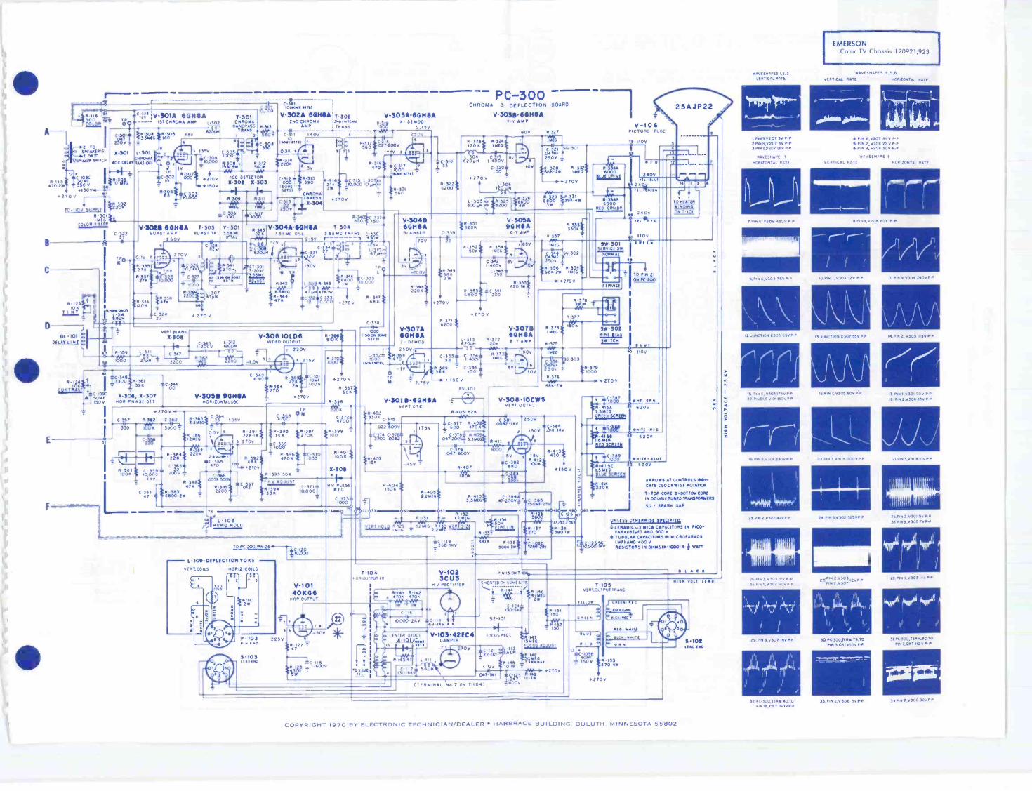
EMERSONColor TV Chassis 120921,923
WAvESHAPES 4,5.6vERTICAL RATE NOR,ZONTAL RATE
0.1A111110 011661**..
4 PIN 6,0207 94v P P5 PIN 2.02013 22v P -P6 PIN 90206 30v P.P
wAvESNAPE 8VERTICAL RATE HORIZONTAL RATE
8 PIN 1.0208 65v P -P
10 Po 1.0304 120 P -P II Po 9,0304 2400P P
I3 JUNCTION 030755, ; 4 PIM 2.0305 115v
16 PIN 7, v305 60v P -P
MEI24 P196,0302 325FP P
0.3,120
30 PC 300,116179TOPIN 3.CRT1500P P
33 PIN 2.0306 3020
17 P191.0301 901/ PP19 PIM 2,v309 P P
21 PIN 3.6306 t0vPP
25 MN 2.0301 5v P
35E4719 v302 7vP
29 MN 11.11303140 p p
404 kielm
51 P9500,TER/1.00,70PINT.CRT 112VPP
rZi34 PIN 70306 90v PP

1290EMERSONColor TV Chassis120921,923
APRIL 1970
rGC
SYMBOL DESCRIPTION
ELECTRONIC frwETTFTECHNICIAN /DEALER
COMPLETE MANUFACTURERS' CIRCUIT DIAGRAMSAND TECHNICAL INFORMATION FOR 6 NEW SETS
00 r
1
Gr.
G.G
"00011'
100110
VHF TUNER
00o
EMERSON PART NO
R107- resistor WW 3.511 =10% tol 18wR109 -resistor WW 9711 =10% tol 15wR 116 - Color control 500 (th 120920 and 921)RI17 volume control 1M (ch 120920.971)R121 -bright control 250KR123 - tint control 10K (ch 120921,923)R124 -contrast coot 1000R129-vert hold control IMRI30- vert size control 2.2MR134- vert line control 50KRI47 - focus adjust control 15MR148 - resistor WW 50M =10% 101 75.kyR212- odl sound rei control 15KR224 - self sound rei control 75011R247- AG( control 100KR301 - color killer control 1MR393 - high voltage odiust control 50KR4154 --green screen control 1.5MR415B - red screen control 1.5MR415C - blu screen control 1.5MRV101 -voltage dep resistorR9102 -thermRV301 varistor5E101 -selenium rectifier focusX101 -diode horiz centeringX302,303 -diode ACC det2304 -diode chrorno thresholdX308 -diode high voltage pulse regulator0301 -crystal 3.58MHz ostD1101 -delay lineCI084 -cop elect 250µf @35010(1088 - cop elect 500 @350oC108C -cop elect 30µf @350v .C1094 -cop elect 250Hf @350n ch 120921.923.C1098 -cap elect 80µf @350o ch 120921,923C109C cap elect 50r.rf @SOY ch 120921.923(109D -cap elect 100 @25n ch 120921.923C214 -cap cer 1400 -=5% to! NPO(256 -cap cer 4741 =5% tol NPOC302 -Cap cer 100 =10%, tol NPOC322 -cap cer 27pf, =5% tol 500v NPO(324 -cap cer 22pf =10% tol 500v fsWO1332 -cop cer I 2pf =10% tol NPO(346 -cop cer 100pf, =10% col 060IC201 -int Or AFT
chroma board ass'y comp ch 120921,9231101- xformer filament1102-xformer audio output1104- xformer horir output1105- xformer veil outputT201 - xformer sound take OFFT202- xformer sound IF1203- xformer det1208A- xformer AFT disc primaryT301 -xformer chroma band pass1302- xformer chronna outputT303- xforrner burstT304 - xformer 3.58MHz oscL105 -filter choke power supply1108 -def yoke oss'y1201 -choke coil 1.80hL203 - toil 47.25MHz trapL207 -coil 4.5MHz trap1210 -choke coil 1.8µh1216 -coil AFT take offL301 -chrorno take off coil1.304 -peaking coil 6200hL305- peaking coil 300µh1309 -peaking coil 47AshCB101 -cir brkr
394302397215391026391028391033391024391032391034390951
390952390950397208390954390883390953390949
Poo R301390879390879
390879
387186397187397233
817123817120
817177817172
817172817175709010
925707925707925707925708925708
925708925708
929218X928811X928820X928809X928824X9288050928829X
815215471853730152734248
738229738218720558720471
720472720577720563
720575720580720583
737059
708516705049
708427708432705049720576
708438708430708531
708521808022
Tilv I1514 01001
X2-201GICulT
IC 201
.
DISC1111.4.54,04 T4.5
7-2018A 7.2088
a%.. =v7
C60.,250151--Cz091.217
IC 254Lon
I'000a
,
Itv
4.
C,02eZ,i
' Sr" 1000 5
0.212
1 clcicoL
I''''4
. Val25 M
L
-2°319C 214V11 C V. 140 R 216
i1
if.,
L-219 w 262
7 2 SY
C 2561'.4' I.'
2153 lott
1r6p2 Iwo7$
PRI
SIC
C 26056
DC.2610t I C10.23.5; 1-216110.1 rft0u10
;1G/7i
NOTE
VARIES WITH SIGNAL STRENGTH
.5' r /
V-204CMS
t000T-204
*-1.5V
C 213*1000
C211000
;02
111
MAIigra
C.25947
250 v.010 1 .T-205 V205
1ST TOTS° mos.1350
,50v S. -14(
R 217C10.200I?
IAV
C. -02001N600
CIS2O113
042;5$
T-206
20,10 ''"Cu,,, F G0PT 201 V-201 4C116
L_
IPA
200 TOMO IT,
270V s 3
2709
1409
40V C 22,
Iew' MATCHED PAIR
RtierseR :210 C-21915001w woo
C 2221000
3
/7 201 90V
1-2011113.2n
1 202
56 u
V-205c
41J7 5100. 0/C 404
220W,
605110 OCT
X -20i
t 204121.'-I CO
T-207500101010 t,
re 0.1
2 20V1
I
R220 if. C211034
L.1 2118
R, 0711 (1.800t 03W- 211p
IMP
I 441171L ST ...AV.(LIMP TLINIII
1=0
WO TUN/ ItI
100r,R MAPI
5 V-104 3M05,30K i
C-10; Ft 103N WI .1.22 001 -
11110 V
INV 103too 7417 C011740a1
81.4NuAk MT DEFEAT111±I
0.10111111151,11-101,1rS103 111182 mut
0,91 1 ISG
V1C1 AFT
L101ILDEGAUSSINGiLCOS
L103 L
It 103.1 104 API.51005 50101.00 1
RV 101 RV 102
Cl-101CIRCUIT 011105/14
V-105 5047 51.45 I ,
0 104.01S0 1 9C 651-1XER
C 226!1000
1
IC 239200v
$11-2391500
P C -200VIDEO, AFT AND SOUND BOARD
,OLIN.
30T202 V-202 6MZ6 T 203 V203 6405A I00.7 DC MOP SOLING OE .....
R.203.0e
204
120V
2.5V
b
R 206
3300
.150 v
+27010
,0 13viola 047S-202 L-207
1)4501( ,44206 C 231
14nIC 22 t
+ 2 0 v
5604 SC
C 22
11-224750
111.11.22112REJECT
V -2011A 4.118A241 miEDGC
220AV0 $ IIV
Cr, 30,v3 ro2 7
G7CTu.
5 0240..JAIrn_LAL_ I
IC
2030110 *24,v 101 10105
nrrc,0
6812WR 243
-e +270 V
rIse
-I
1
v
R 228
2 WC.
P
L-. 09 C
6(111-4-0
wFt 225 I ,T 2 94 300 222t .1300
2100 0
zoe
068'0C
C 232240
,°+0 sC 52634e2 yN
C 2106800
N
Stu!
C 211001.2
0Tie,?
270
2503 ALK01304/1PuT TR-7 - 7-102
I L._ MEG'VOLUME--
1
6V
V207A GOMA13, ,..00 AMP
11,"
4150v
i023500
0.231t,c,mi
V20711.14MA5NC -AGC-IINROm AMP
+1500es +2 70 V
IR 119
fly
9910, 210206 .15094-
l 5!151 120V
(1-I
0120i-i1224
0.4,303
C 236
R-234
120V
C-237t000
272
33
0.12,2504
01001,115
R 12201e + 270 V
1505w
Cl5f,1,5 R 24939.1
R 251390
2IiR 248 (3300246 1800
224
27010
R 2471000 G C
2 5 247.4
150
1/401111.601111ASvNc 5(P
1400
15v
0-2532 26116
TO TUNER e+
2045600
+1500
6104-9
14481Luvr
1144(411C 113
1000 iitvut
TO SW- 301 ON PC 300
Tom2r0111:016,
1.1.1411.1.11
SI -1011AS Rfcr
107
ON -OFF SWITCH565
2241 00u8/1R RECTIFitie L1043ION vommet CONTRO, so 1o1351,04 C 105 51.102,51-103 FILTER CROAt
MOCK 051011
sw-lotON
lw_LTSLI
.7713 SPEAKERS
ON STEREO
PHOPO RADIO
+ .r
311131
451
1
1
81.104
uic09BICtI/4101
1-101
aro! 0,,=C
1 03600vui
TOT 101
NI
sw-10184
z r
41,1
:LsfvurrRSWITCH !
ley Of 00-01/ SwiTCNI
:
P 101
vROAd o7
3Tt R 10 .100147
NEATERTRANS
T101
1=0
TO PC -3 PIN 87114
16t4110V
V 204
R 113+ 270V SUPPif
350W 175v2
A1OC :00060*: -4..0C 000Z-.7oflo*C ,054250i0350+
R II
1800 15W.W ISO v SUPPtv
M.0 109A 1098250 350v 50 3509
v-2015
V-202
C.i718
0206 102055 5
0.1
i3110 ON Wen
R 1155211
T SITU
S2"2,SOV
Soi)09
NOR 8101 SNAF1 GL11103
bb
io.000T cs818., cam c,o.srC 247
1100
TO PINSIal v-203 v-207 0200 v 308 v 306 0-307ON v 106 R III
IR 'wr,Am_....,A2, IALLAL..1.__LAtR1011 49 ;SW 2 ; 44 As AI
&37.15w1C-104 0-103 v,101 9-305 v 302 w 301 0.304 030320611 75V NP R'109 5 5 . On s 5 5 5
7 C-340. '0.000
,,220to97-150)
12004C.60CPS
C 806
27.2009
150 1W
St 801A
12E401
.1....,iCRTIG/47.11°131 Ut
0C.0684.2001,FT AC
.o2SRiG0T R -G VERT L INES
1 1
318018 St -901C8034 S. C R 806
ICX) 1
LIFT VI
R 80747-2*
12 2000 11,-#R5 20:30
1EFTrat____ItORLINE
1.8021710111 R -G1=3
j"'LlorCONVTOKE
0 I fmil)11
*
02
ir ailE-Tiutsv
-44,4-R-6ovERT Sul
R 813120
4044
5111
12LiWV'
9,91. 9.9.14
;SO I 47 0:1, .ozo_20 St SOID 4
v101811.11711T
9 u
Tit LOT,
CONVERGENCE BOARDP 102Aloo 150
1290 COPYRIGHT 1970 BY ELECTRONIC TECHNICIAN/DEALER HARBRACE BUILDING. DULUTH. MINNESOTA 55802
4111---RY
*Ps
ed.
ISyI
_08f; Cui
iLOY4
.10.431007
TA u4 64601
45474.7-7
,02
Jo-22!.
V49
6410
07
D tad 7 v
AG, DV
R6505277? -75 C
.56 n T 04 C
AT
0..
22°vI
eTl
(0
-WO
O
VHF TUNER
04 58
-KS
wif Au -52.5C
117 B45944SS
AlaCOL&MtKLLE
TO
7.4 70.-11702 4050
- 1ST CHROMBalVD 55
c4:1e51SUPPLY 1
4.
,00v.71.!J___
2207
2.4v7or
SYMBOL DESCRIPTION ELECTROHOME PART NO.
7703 - col burst gate 21-1053.021901 -coi horiz stabilizing 21-334-051.104 - co sound quod 21-1084-011103 -co sound take off 21-347.02T101-26 sound IF xformer 21-389-01T202 -coi 1st IF interst xformer 21-392-021902-coi saturable react (lin) 21-1055-01nuoi -cod delay line (.8µ sec 680E1) 21-1054-01L253 -coil discriminator 21-1040-011901 -horiz output xformer 21-220-01L910 - del yoke 21-113-02
1401 -power xformer 60Hz w/stobilizer brkt 24-10140-011601- vert output xformer 24-100016-01T102- audio output xformer 24-80080-021402 filter choke 500µh 24-110024-10C8401- cir brkr 1.75o 26-65-09F401 - fuse 8A quick acting (use w/sleeve) 27-14-08SR901 -boost rectifier selected 28-22-22
41-228-2341-228.2541-192-0641-227-09
R913- contr 100K PH (horiz drive) 41.192-08R329 contr 7M (red screen) 41-227-28R603 contr 3.4M (vert lin) 41-227.31
,
R813- control WW 1w 6022 (top horn lin blu)R807 cont WW lw 15012 (left yen lin R/G)R216- contr 22K PH (odi sound rei)R235- contr 75012 (sound re')
ELECTROHOMEColor TV Chassis C-8
R920 -contr 2.5M (HV adj) 41-227-37R909 -contr 200K (horiz hold) 41-227-34R705 contr 2.5M (color killer) 41-227-37R930 - contr 15M (focus) 41.251-01R406- resistor 30w WW 105011 (w/brkt) 42.14-138929 -focus div resistor 140µa ±10%
160M (28M top) 02.100651-01R914 -VDR red dot 42.23-01E401A-electrol 100µf 450v 44-203-15E401B electrol 50µf 450v 44-203-15E4010 -electrol 20µf 450v 44-203.151402A - electrol 100µI 450v 44-202-26E4028- electrol 30µf 450v 44-202-26
U91_1.152004 - 4305
240K5%
* f1,992
St
TO 4705.8PM 2 BLANKER
;:tz:T56
.
TJ. 4,iT
v1OAr
14 L EL.244 67.44C124.15/4 4TO 267
/ yy.
943 2171L LEA C
C 716
6.500
To,4a
?''.
DV
CT
20
RTIT
5%
v 702
6E172740 (ARC.
8NOASS,fr. ccw.
111
StO
APO
ICStill68
TO .7C T.TO 0756755
265vSc 7*
.04
TO le. 265v
LULA= v2661184
BLAST GATE
5. Gun,
A
cpp. ;:kr.zno
721
517R
-uT.TL.t-
St
40
3.5v30,
AM. WE
115519
5805%
LJOS 156000c4u428L
70;1!?
5
V7461
r TNT'
I 11
, 1 La''1 05
5%
vsv.
M3WKta Et TO
-r1000Ft VS At_L
TO2650
743
TO
100p55.
voV
C7i7 Amic470 CC
24
OV
0530,.8.58:
C7201
T 04 -
1/26GNIA0E7E44 ACE
,LLE111DE T.
'14 5700
4054
901TS M
.4* yC90,51RT
'-94fi(903
4.7 *54
2004
650
0904
1254KS
447 3900
!US567
14,5%4Vv.
C!"cos.
P.K
19455%
200.17909or)
410012 PEOL D
700104 AULT.
,-'
___L
47 i X
CP
cy gAsz
n_7: , sTr, .
..TO
gm, C 708 4 C 506
En
'16471-a 5,5
REA 5%
931±544
%
56
LLS9590 s 1007
31. 100fl
4912
5%
RED DDT
00. 4.1LT,
O
1561
!KV
5%
1"2 6DX11
2504re,
BLANKER
eig A2/104 if
A071,/. Out.
5%
`41`..7;21.
= =12C1152
27/D.zJEO* 10K
COE4EST
} SAUL
A t BRIGHTNESS
f2y22-4L/N Lag_00 * 5K5%
I76 iDIA I BLUE
5%
O
E 301
C417
---tnt-y2SAJS4ox*
0325
4526L27
DRBLLE
411"
r`"'111".rxr.::::
S232_10
800 sit4q.W
A75.5.t
v 705 -I- I/21in
34 4.7 us.
56
,I
9011 PULSESOURCE -A'
ty&,
-92 t2455, 5.6 It
0 TO405V
4224 80057 SOURCEin 8750
.0.V 141V
REO DOT nye
T 602 J1.227.
.00.,Z LIM'KWIC%
TO 405
OttObs110 MO,44041
Omo
(HOOT I
44.48AC7 CA045 -0E5
1 032.1
3CU3AOOa(7±
AEC)
o
09.600 0
.570
*
(TooICR
4050759KKK
7
BIA*0SCONTROL
F4L,
TO Pix Toe( 56 901
254V7401X 44 4t CL903 60Z:e0,,y , 28 la TAP,0000 1930
V904 15 IV'. 6EC4 FOCUS
044075-4
2.1530
C9,8300 5003101 3700
TO11-- 900ST
0927407
JE,02T°16104 .5
C917TT.,.5sv
OSPO STSTED
SOURCE12000
-`1M5%
4050
TO 4050
TELTEL./TEL.
11106
littO
tattatop At aorowo o a oil oOt....10,
/Kota oca
gral vat.
r ..."
%ak CA 5( MAXUS OW,
VIA Len LAIC.V MOM
e co4 Vivm
CHASSiS TTPE C 806 3613i 01
SSA I
COPYRIGHT 1970 BY ELECTRONIC TECHNICIAN/DEALER HARBRACE BUILDING. DULUTH. MINNESOTA 5 5 8 0 2

1293
1200 =RC
60Hr
PHILCO-FORD
TV Chassis 20S32/A
APRIL 1970
ELECTRONIC 7.777=E SYMBOL DESCRIPTION PHILCO-FORD PART NOR14 -5 6M AGC delayRS -151, contrast
TECHNICIAN / C48-240/240/160/50 @MY B. 8ther 30-2601 33 R23 560K. AGCL1 - 180µh, plate series 32-4762-7 R27A -680K. vent biasL2 -330ph. plate shunt . 32 4762 20 R40 voristor. 500v @10µ0 33-1373-6L7 -quad std del .................................. 32-4876-1 33-1381-518-4.5MHz trap & 5TO T1 -audio outputCOMPLETE MANUFACTURERS' CIRCUIT DIAGRAMS32 4688 13
R63 -fusistor
32-10008- 7T2 8 filter choke 32.10118-2112 -ton: stab 32-4754 3
AND TECHNICAL INFORMATION FOR 6 NEW SETS N3-vert int .................................... 30-6030-12 T3 -horiz output
32-10013-4
T4 -rent outputN4 -hunt osc ................................. 30-6057-1NS -phase comp. VR1A-C - 50K vent size, 2M yen fin,
32-10012-630-6035-230 6058 2 33-5595-8N6 - isolation, CRT 60K horiz dux
MODULE "A. IF TRAP)
M33 I-42 75 MHz L13
IFLINK GSA
FlVHF TUNER
T T164E
UHF TUNERTT 152To
CIIT kr6TUNER
8+
447 145 V
IST.IF 7
ToC17T
mittATUNER I
AGC
-2v W/NO SIGNAL I F+.2v W/SIGNAL AGC R47
220wv
C30.0015
-t-GMV
M12AGCTP
OV W/NO SIGNAL22V W/ SIGNAL
92
3 C35
FIN GMVT.00124 =
5%
621
LII
-a C37=-0033GMV
R54 R55186 330IW
GUS
MT
7
R56C414 1100
.0015
R48C41 560
10022
180
MODULE 8 (DETECTOR)r,Nt, 7 I
1
1.8
I L1LIB ; :15
1
' '4 50
1.5
i1M29+145V
RI
L9
628
P-7 I(
145 mHz-L
I
TRAP
TL__
I/2143dS1F
-74-
63- -SNDTAKE 1
OFFJ
L JWY
.0014062
f270I
GMV
C2027
T4.76
L
+14sv
RIO
Vi R18 /150K
4CS6 -,44.-4C4 1 (3DET
5110931 T.0015 .0033VI -4, M4
7!16 VR8 R4 71M
VOL
s sr
15
R31
C10
1.0082GMV
18K
R265605%
R376801
Cl
IIOOV- R4
C24 -1-
15100V
22R12
OK
600K
SWITCH ONREAR OF
VHFTUNER
VHF PILOT L ITE11611111 II NE2H
taek8e C22SYNC. SEP
/--
680
SYNCTP
TO +1400ON VHF TUNER
33K
336
!NM III NE2HUHF PILOT LITE.]
-
R3
-158 ISOK
+Jo.560K
R44 =5" 156
M27A
8.'1120
01Ie"5%
= 3
CI3R36 -.00821,86 GMV v
1/2%Y8sv GATE
2 y R2
336t R16j 39K °2;1(
+1452
F1151. 2M
R14
5.66
611V
31/2 106 R8
N.I.2
R4526
To HORIZ.OUTPUT GRID
D/C50
-.1.22
400V
I- PART OF VR8
ce,...e0
I ON -OFF -1SW
R63FUSISTOR
311
PAM
Om NZ 6
4co coI In
o
CSI
680
0403 + .C480 160
tisourI 2002
SWITCH ONREAR OF
VHF TUNER
TO +1400 CLOSED ON CH I
ON VHF TUNER
R60
68
V4 V V3 VS v2 VI V6 V9
:0221
T21F.C.1.6H
+--1-a C488I 240LIF= 200V
41-°C48A124011F= 200V
sw +140V
+I45V
R6415K
ITnflusiii7 11Wn
I F, 1;4 I
M3I3 a 4 5
V8 CRT
T I28C_.0015 470661V = GMV
-1511
02
10082
GMV058
R30I 565%
R304394
L6
220
10K .005 901 31
MIS+145V -
13K
6121A R225%
(FOCUS) .--vv."--100
fC48C5µF200V
R15426-8K
M9
VRI151St5
CONT
R298.2
zyyK 22A
R5 33M it1.56
N1126i,
2000 LI
C5 180R3 8418 owe 7
ixv 106 MT,
lay 220
9
1451
1/2 elY13AUOOUT. CI
.0082
R8
11K148
R7100
614 TI.071
ILA
a
8E0
MI
+145V
TI(A.0 T.)
IN YODELSCI4 WITH PIINITE
00132,-I
LISTENINGGMV J._ JACK
LSI its.- 47
18198.2M
4119
L2
330
1/208659 VIDEO OUT. -
01 I
09
3
G4A M214 M27
I ISC,v 300v= FOCUS
611 R9
3906R24A220
9 54
if420A22K1*
R39 4.617II
- -- - .047100V
+1400v18102M
VERTLIP
C29
I-61810%
2
111
+140V
:6806
C27 10039100V
/746
1365%C33
--3901001 15%
- C340039
Re9-7505%
III t N4
106
121
3,1 -?glzLi) 5
22K
TP 1208 6 1HOR OSC
84(..7-918
NOR OSC
R57
686
3 24VRIC
fH0,6KHOLD635
1/2A111VERT
C26OSC0200q.15
.0033
, 3.96
L -C344
1330
11
C1033 624
401007.V
412KC32
2 8047
,0400V
00472000
61DDI50H00308Dmi
22
VERT
VR4100K
BRIGHT
R1A Fni100K 2K
MS
I 4E1
2
CRT;
2ORP4
6
MV
C3A
+145V RCA CAirsuA
1 75MI
76 330 9K pas Tu 1
I 5256f I
To NOR. OUTPUT
SCREEN'9'
RI
l.56
+145 V
C39
-05
VRIA 50011
IC23-.047600V
R40der 560v
Qicm
615V
M26
14410
M301116
84043.96
625
835-68061W
RI
oil
C52047
.640011
I VERT.1;158 SIZE4561
v712 161711,46
HORIZ K V
OUTPUT
33°11
5,9
209
To N.1BIASR45
R502.7M1W
R34.4.10 330
= I W T.M2I !MIGHT CONT
VR3....h"8"
3KWIDTH
+1450
M27 R41+300vFOCUS 2.2
C49180
01 /T
ToGATETUBE
6120
6806vivr CI6
-00821GMV
4-140V
lifvERTYOKE)
T 3
HO AFIERIG3-163
623 L5
21 5.614 C53
Fti 3 TO 1412 A -_ts
K 2 2M
R62
4 71
H ToCRT
VR3 -3K width 33-5620-1VR4-151( contrast 33-5623-13VR5 -100K, bright 33-5623-15VR6 - 40K horiz hold 33-5623-12VR7- 150K vert hold 33-5623-14VR8 - 1 M. volume (205326) 33-5634-9
PW panel ass'y w/comp 38.10543VIE det panel -less comp 27-10561-4VIF panel -less comp 27-10561-9tuner UHF, T1152 76-13827-1tuner VHF TT215 (20532A) 76-14150-1yoke 8 cable oss'y 76-14170.1
ELECTRONIC TECHNICIAN/DEALER is pub-lished monthly by Harbrace Publications,Inc., Harbrace Building, Duluth, Minnesota55802, a subsidiary of Harcourt, Brace &World, Inc. Subscription rates: One year $5,two years $8. three years $10, in the UnitedStates and Canada. Other countries: Oneyear $9, two years $14, three years $18.Single copies 600. Second class postage paidat Dansville, New York and at additionalmailing offices. Copyright 1970 by HarbracePublications, Inc.POSTMASTER: Send Form 3579 to ELEC-TRON IC TECHNICIAN/DEALER, HarbraceBuilding. Duluth, Minnesota 55802.
1 293 COPYRIGHT 1970 BY ELECTRONIC TECHNICIAN/DEALER HARBRACE BUILDING. DULUTH. MINNESOTA 55802

1292
3 1V1 15111,3 308,
e
IN1 lSVpn 78/5 4, 98Vpp 30.,
4 3 5Vp ta 3087 5 IV] 31,"/ 30
9 181 >VP p /8/5 .1
1, 880007875
6 I, /0vo o 30 V7
10 10) 13,79 7117582
78758,pv 17 101 750,, 7845 '13 181 112,11/ 7875,., 11 30VP0 787587
17084444 717384 18 IV) 70V448 bw
C003 331005
1104112
'33
T201
0-
802POOP
Co.)
NiaK
101/80
17 L1./1 I00Vpp 308, IR) IV) 70/88 30117
020) 02022 SC6820 2SC 682 -&17.4 Pi% IF 11,109 12. PI' IF *MR/
L202
R101100
at08)10
4203IK
210'
C2041
L2 L03 ...1000
COOS
RIR.00P 1200
T $CoOd
11204
Cr] 442322C517AW
ItS01O K
IC 23401
X
2C5)?150(HOC
%.1471:O 1104
11/0
00
81704SO
070110/1105
S.&OK
011030.2K
1.±L.Q1
'64'L204
8804wo
41--) (7172 01 )
OW
";!:: 040
CNN01
014
11121ISO
11100000
0701
2SC458©IPHAIL SPLITTER)
I
c;o40701
O 702C/03
04?
II
1170?33
C 703
C7073
0112
0601
2SB77
1004 a) t. 0.20707HOLD
T701
..,.C857
;iIR S 177? .,..
32201 yr-WA,"
0111
1111 11k
8.0.11.b WE
YaV
07022SAI5I.:.0110) 0
:0
02032SC717
1388 P10.18 111/P)
L206 L205C214
IC205 1144
011-1 Rt00 R012-
27 IRKl 0210
201*
Cl,,1000 &OP7'
Ci0:11$9 RSVOCOI
IGO 112.3 *0C1I 0.13
c.
8211
K -UN I T-132
Inca est;"
1-1110
0202VAN
R2572 7K
8211lK
(.207
217
821
ELECTRONIC Tri=77TECHNICIAN / DEALER
APRIL 1970COMPLETE MANUFACTURERS' CIRCUIT DIAGRAMSAND TECHNICAL INFORMATION FOR 6 NEW SETS
:CM01
080)2SC454 t1177 V.0E0 44441
06022SC85612na 00E0 00,1
MONOPOLE ANT. EX VHF ANT75 OHM 300 OM
417172708
KN K17
11370
270
20
4
C253
06022SB77*(PERT, CRVER)
11110111 338
cr VW5
aMaSOO
Rai
IC MN8205
00OK
SR it 7120
0 703258570V 0(081 owe)
7004)
.1C234
0603258541V
13051. 051011.17)
001
RHO3 3K
#13070
01
02042SC458©
1413C AMP)
L-112111-14fp!,
cza
nut88
1.1302
daNZ R003
?V 0K
0 2111
Koc
5001
;114014411.4% r 3)011
..... .,.0000 6.38 0
( to
MEW a i ROW7"Kleo-, &so CO011
10/11305
03 03
T301
AIRLINETV ModelGEN-11960A
SYMBOL DESCRIPTION ADMIRAL PART NO.
R111 - 10K, I 60B14-103R208 - 1M, vol cont w/sw 75C120-1R320 -30K, contrast cont 75C121-3R322 -100K. bright cont 75(121-2R4024- yen lin cont. dual 75(95-6R4028 - height cont. dual 75(95-6R421 -1M, therm 60464-1R422 - 1.2M, vert hold cont 75C121-1R502- 5.511. fuse type 61(48-1C135 - 39pf. 5%, NPO, cer disc 65010.347C327 - 6.8pf, 1/4%, 500y, WO. cer disc 65010-102C406 - 330pf. 10%, Sky. cer disc 65010.266(430 - Spf, 10%, Ikv, N750. cer disc 65D10-345C5044 - 150rAf. 165v, elect 67015-393C504B - 1500, I 50v, elect 67015-393C504C - 2000. 150v, elect 67015-3931.202 - quad coil 72(132-77L401 - Nora lock coil 94017-17T201 -audio output xformer 7901.23T303 - sound takeoff xforrner 72(185-S1401 - yeti output xformer 790100-171402- def yoke ass'y 5151. 70001089-21403 - hori: output 'dormer 790117-1CR401 - horn phase det 9385-9
tuner Uhl. 94E361.1tuner VHF 94(360-1
03012SC 454®
ouND14 Akin)
Ts.C38228
LBn
y-BIAS
WW1
a
70/111WCMS
VDR601
.csits
"VI WeOK
71102
a
a
0.V.12octss
7:"
02052SC458 CGC GATE/
004
103V
SR 7031111V -0C1,121
8285270
2304K
C304470P
trzLim !CNA.51,0,
RIO]
COO)
-P:.1°511Do.$2°
C30 H:3 L303
,;01IR
0 3022SC 454®
2/81 SOUND IF AMP) T302
L302 -,,
4040
81010 020
0 4012SC 458 ®
W070 DONE AMP 11(10
41 R
5,344
6E1
540
25
53075
-NWt/H1,C30.
43011 X01 0101180340
.2
030?
0 4022 S8368
!AUDIO OUTPUT)
4130 I4)
000
CR12
"%17
$301DC
BATTERY 12VStv 901
101 Cr R301
VOLUNE
514017 ow.
07
120V
60Hz
1292 COPYRIGHT 1970 BY ELECTRONIC TECHNICIAN/DEALER HARBRACE BUILDING. DULUTH. MINNESOTA 55802
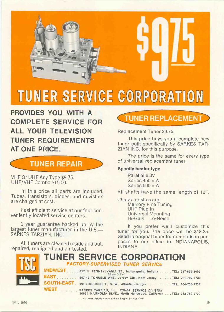
PROVIDES YOU WITH ACOMPLETE SERVICE FORALL YOUR TELEVISIONTUNER REQUIREMENTSAT ONE PRICE.
VHF Or UHF Any Type $9.75.UHF/VHF Combo $15.00.
In this price all parts are included.Tubes, transistors, diodes, and nuvistorsare charged at cost.
Fast efficient service at our four con-veniently located service centers.
1 year guarantee backed up by thelargest tuner manufacturer in the U.S.-SARKES TARZIAN, INC.
All tuners are cleaned inside and out,repaired, realigned and air tested.
TUNER REPLACEMENT
Replacement Tuner $9.75.
This price buys you a complete newtuner built specifically by SARKES TAR-ZIAN INC. for this purpose.
The price is the same for every typeof uriversal replacement tuner.
Specify heater typearallel 6.3V
Series 450 mASeries 600 mA
All shafts have the same length of 12".Characteristics are:
Memory Fine TuningUHF Plug InUniversa MountingHi -Gain Lo -Noise
If you prefer we'll customize thistuner for you. The price will be $18.25.Send in original tuner for comparison pur-poses to our office in INDIANAPOLIS,INDIANA.
TUNER SERVICE CORPORATIONFACTORY -SUPERVISED TUNER SERVICE
MIDWESTEAST
SOUTH-EASTWEST
817 N. PENNSYLVANIA ST., Indianapolis, Indiana(Home Office)
547-49 TONNELE AVE. Jersey City, New Jersey
938 GORDON ST.. S. W. Atlanta. Georgia
SARKES TARZIAN, Inc. TUNER SERVICE DIVISION10654 MAGNOLIA BLVD., North Hollywood. California.. for more details circle 137 on Reader Service Card
TEL: 317-632-3493
TEL: 201-792-3730
TEL: 404-758-2232
. TEL: 213-769-2720
APRIL 1970

There are now eight new SK devices to broadenreplacement coverage in AGC, horizontal deflec-tion, vertical deflection, damper, and audiostages of color TV; and in transmitting stages ofCB radio, amateur radio, and communicationsequipment. Result: RCA now offers you acomplete system of 47 "Top -of -the -Line"universal semiconductor replacements. Usethem with confidence in all entertainment -typeelectronic equipment.Every SK device has electrical characteristicscomparable with, or superior to, those theyreplace. And in virtually all cases the recom-mended SK replacement transistor, rectifier, orintegrated circuit can be installed withoutchanges in mechanical mounting arrangements,circuit wiring, or operating conditions.Get the SK habit. You'll save time, reduce call-backs, and win a reputation for making yourcustomers' sets look and sound like new.Maybe even better.
For complete information, call your RCADistributor.
RCAI Electronic ComponentslHarrison, N.J. 07029 ncn
8 more SKwaysto repairand forget
20ELECTRONIC TECHNICIAN/DEALER
HUGH "SCOTTY" WALLACEPublisherChicago:
(312) 467-0670
PAUL DORWEILEREditor
JOSEPH ZAUHARTechnical Editor
KATHIE PONTINENProduction EditorBOB ANDRESEN
Graphic DesignLILLIE PEARSON
Circulation FulfillmentJOHN KESSLER
Manager, Reader ServicesBERNICE GEISERT
Advertising Production
OFFICES
757 Third AvenueNew York, N.Y. 10017Phone: (212) 572-5000
Telex: 01-26286
43 East Ohio St.Chicago, III. 60611
Phone: (312) 467-0670Telex: 02-53549
1901 West 8th St.Los Angeles, Calif. 90057
Phone: (213) 483-8530
Harbrace BuildingDuluth, Minn. 55802
Phone: (218) 727-8511Telex: 02-94417
MANAGERS
HUGH "SCOTTY" WALLACEChicago: (312) 467-0670
DEAN GREENERChicago: (312) 467-0670
ALFRED A. MENEGUSNew York: (212) 572-4829
DONALD D. HOUSTONLos Angeles: (213) 483-8530
ROBERT UPTONTokyo, Japan
I.P.O., Box 5056
CHARLES S. HARRISON,CY JOBSON
San Francisco:(415) 392-6794
HARBRACE PUBLICATIONS, INC.
JOHN B. GELLATLYPresident
RICHARD MOELLERTreasurer
LARS FLADMARKSenior Vice -President
HARRY RAMALEYVice -President
JAMES GHERNAArt Director
EDWARD CROWELLDirector of Marketing Services
ELECTRONICTECHNICIAN / DEALERWORLDS LARGEST ELECTRONIC TRADE CIRCULATION
APRIL 1970 VOL. 91 NO. 4
37 TEKLAB REPORTThe object of this month's report is the hybrid chassis used in the Craig 115sq.in. (15in.diagonal) color receiver, Model 6304, with a complete circuit analysis and referencediagrams.
41 STEREO SERVICING WITH A SCOPEBy Robert L. Goodman. Part two and the conclusion of this informative feature tells youhow to make the most of your service time using scope techniques to troubleshoot andrepair solid state stereo amplifiers with many excellent hints geared to increase yourproficiency.
45 CURVE TRACER FOR SEMI -CONDUCTOR SUBSTITUTIONBy Jud Williams. This timely article explains a procedure using a curve tracer and anoscilloscope to produce the characteristic curves cf a semiconductor quickly and easilyon the scope face to allow the technician to compre transistors for replacement as wellas telling him whether the transistor is operating as it should.
48
50
51
FROM SCOPE TO VECTORSCOPEBy Charles W. Janecek. This is a practical featuretta describing a method of using an os-cillosccpe as a vectorscope and some of the advantages associated with this technique.
OLD TV SETS REDUCE TAXESBy Leoo Rovik. An interesting and timely article which may give you some money -savingtips on ways to get rid of old TV sets that have been gathering dust in your shop.
TESTLAB REPORTOur lab technicians this month dig into the dual trace, triggered D54 Telequipment Os-cilloscope and the Eico Model 240 FET-TVM to provide you with some good general in-formation on the characteristics of these .snits a; well as our comments, pro and con,on their operation.
22 EDITOR'S MEMO 62 DEALER SHOWCASE
26 NEW AND NOTEWORTHY 70 NEW PRODUCTS
28 LETTERS TO THE EDITOR 80 NEWS OF THE INDUSTRY
32 TECHNICAL DIGEST 82 CATALOGS AND BULLETINS
56 COLORFAX 84 ADVERTISER'S INDEX
COVEROur cover photo this month depicts the earlier type circuit boards used in the RCA CTC-31color TV chassis which is now out -dated by the use of smaller, transistorized circuitsin the more modern color chassis now beirg produced by RCA and other TV manufacturers.
TEKFAX 16 PAGES OF THE LATEST SCHEMATICS Group 212ADMIRAL: TV Chassis TG2-2AIRLINE: TV Model GEN-11960AELECTROHOME: Color TV Chassis C-8EMERSON: Color TV Chassis 120921,923EMERSON: TV Chassis 120969,970PHILCO-FORD: TV Chassis 20S32/A
A HARCOURT, BRACE & WORLD PUBLICATION mr,Harbrace Publications, Inc. ABP 1,12
ELECTRONIC TECHNICIAN/ DEALER is published monthly by ElectronicsTechnician, Inc., a subsidiary of Harbrace Publications, Inc. Corporate Offices:757 Third Avenue, New York, New York 10017. Advertising Offices: 43 East OhioStreet, Chicago, Illinois 60611 and 757 Third Avenue, New Ycrk, New York10017. Editorial, Accounting and Circulaticn Offices: Harbrace Building, Duluth,Minnesota 55802. Subscription rates: One year $5, two years $8, three years $10,in the United States and Canada. Other countries: one year $9, two years $14,three years $18. Single copies: 75C in the U.S. and Canada; all other countries$2. Second class postage paid at Dansvil.e, New York 14437 and at additionalmailing offices. Copyright 1970 by Electronics Technician, Inc.POSTMASTER: Send form 3579 to ELECTRONIC TECHNICIAN/DEALER,Harbrace Building, Duluth, Minnesota 55802.
APRIL 1970 21

A Complete line ofPhono Drives, Belts& AccessoriesNew - Expanded Listing - includes replacement parts forCassettes, foreign models, and many new domestic recordersand changers.
All Walsco numbers cross referenced in new,helpful 24 -page cross-reference guide.See your distributor today.
ELECTRONICS
Cf/tatTil
GC ELECTRONICSDivision of Hvcirometals, Inc.
Los Angeles, Calif. Hicksville, L.I N.Y.Main Plant: Rockford, Illinois
EDITOR'S MEMO
The Industry Watches
The third in a series of annualmeetings of the National Service Con-ference (NSC) was held recently inPeoria and I had the fortune of at-tending, my first. The NSC meetingsare actually gatherings of manufac-turers, service associations, trade pub-lications and anyone else interested inthe home entertainment industry. Theobjectives are worthwhile as they areconcerned with service problems thatthe technician has to face, parts avail-ability, training, warranties and manyother subjects related to the consumerelectronics service field.
Everyone who attended was givena choice of subjects in which he couldparticipate. It was interesting andpromising to see competitive manu-facturers sit across from each otherand hash out ideas with each otherand with technicians to help theindustry provide a better, more ser-viceable product. Most of the tech-nicians voiced their opinions quitecandidly and were answered in thesame vein. As I said, it was a goodtype of discussion because no one wasthere just to pat the other fellow onthe back. We were there because thereare problems that can only be ironedout through communication. I thinkmore meetings like this are necessaryin our industry to promote a betterimage on all sides. This is especiallytrue lately in view of all the publicitygiven to the relatively few crooked TVtechnicians, lethal TV fire traps andradiation hazards. Let's face it, not allTV technicians are 100 percent honestand are experts in their jobs. But then,very few of us make that claim tofame although there are a few mis-guided individuals in all types of workwho will take advantage of John Q.Public's ignorance to make a quickbuck. We can't play watch -dog for allof them, but as responsible membersof our industry we can help make ita better place to live.
. . . for more details circle 114 on Reader Service Card22 ELECTRONIC TECHNICIAN, DEALER
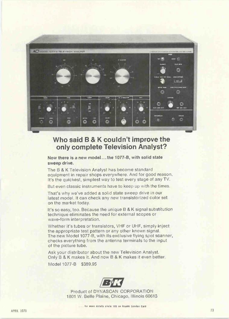
Who said B & K couldn't improve theonly complete Television Analyst?there is a new model ...the 1077-B, with solid state
sweep drive.
The B & K Television Analyst has become standardequipment in repair shops everywhere. And for good reason.It's the quickest, simplest way to test every stage of any TV.
But even classic instruments have to keep up with the imes.
That's why we've added a solid state sweep drive in o..irlatest model. It can check any new transistorized color seton the market today.It's so easy, too. Because the unique B & K signal substitutiontechnique eliminates the need for external scopes orwave -form interpretation.
Whether it's tubes or transistors, VHF or UHF, simply injectthe appropriate test pattern or any other known signal.The new Model 1077-B, with its exclusive flying soot s-anner,checks everything from the antenna terminals to the inputof the picture tube.
Ask your distributor about the new Television Analyst.Only B & K makes it. And now B & K makes it even better.
Model 1077-B $389.95
Product of DYNASCAN CORPORATION1801 W. Belle Plaine, Chicago, Illinois 60613
. for more details circle 105 on Reader Service Card
APRIL 19/0 23


So is this.
It used to be if you wanted to satisfy everyone. youhad to stock over 30,000 different solid state replace-ment parts.
Well, everyone realized that was ridiculous. Sosome enterprising people came up with a bunch ofuniversal replacements.
Then you only had to stock about eleven or twelvehundred.
That was a lot better, but we still thought it was alittle ridiculous.
So two years ago (when we went into this busi-ness), we figured out how to replace all 30,000 withonly 60.
Now all you have to do is stock 60 of our diodes,transistors, integrated circuits, etc., and you can re-place any of the 30,000 parts now in use. Including
all JEDEC types, manufacturers' part numbers, andforeign designs.
That means you invest less money.You don't tie up valuable space.You do away with complicated inventory control.And you operate more efficiently.To make life even easier, we've got a new book
that gives you all the cross references you need tofigure out which part replaces which.
It's available from your Sylvania distributor.If the whole thing sounds rather incredible, you're
right. But why not give your distributor a call and lethim narrow the incredibility gap.
SYLVAN IAGENERAL TELEPHONE & ELECTRONICS
APRIL 1970 25

NEW AND NOTEWORTHY
700
HI/LO BAND FM/VHF MONITOR
AC or DC operation
A Hi/Lo Band FM/VHF Monitor isintroduced. The listener can monitorfire/police commands, accident re-ports, emergency broadcasts, officialbusiness communications and weather.Designated Model APO-5OHL, themonitor has a built-in 117vac powersupply or it can also be mounted in anautomobile (brackets included) tooperate off 12 vdc. It has six high -band frequencies (150 MHz to175MHz) and six low -band frequen-cies (25-50MHz). The unit reportedlyfeatures crystal control on all chan-nels, assuring "on frequency" moni-toring (crystals not included)-Solid-state design incorporating integratedcircuits-RF peaking control for re-ceiver sensitivity-Adjustable squelch-Immune to noise-Tone controlswitch for emphasizing "highs" or"lows." Housed in rugged cabinet theunit measures 83/4 x 71/2 x 25/3 in.Priced at $139.95. Fanon.
FOR MORENEW PRODUCTS SEEPAGES 62 & 70.
VHF MARINE RADIOTELEPHONE
New front endreceiver design
The Model 610 VHF marine radio-telephone, featuring a dual front endreceiver design giving full sensitivityon both simplex and duplex channels,is introduced. Designed for operationin the VHF portion of the MarineRadio Band, this all solid-state, 25wradiotelephone provides dependableship -to -ship communications report-edly up to 30 miles, and ship -to -shorecommunications up to 50 miles.Twelve channels permit full range op-eration on the newly assigned VHFfrequencies for safety and calling,ship -to -ship, ship -to -shore, public cor-respondence; and reception on ESSAweather bureau frequencies. Completetransistorization plus the use of inte-grated circuitry assures reliability, min-imizes heat, space and battery drainrequirements. Special circuitry pre-vents damage if battery polarity is re-versed, or the transmitter is keyedwith a shorted antenna, or with noantenna connected. The transceiver isself-contained in an attractively styled,compact, metal cabinet with cast frontpanel and mounting frame. The unitis designed and built to comply withthe requirements of EIA (ElectronicIndustries Association), the CanadianD.O.T. (Department of Transport)and the F.C.C. (Federal Communica-tions Commission). The radiotele-phone includes mounting tray, micro-phone, crystals for operation on 156.8and 156.3 MHz., and a fiber glassmarine antenna with chrome laydownmounting base with coaxial transmis-sion line. Available optional items are:selective ringer provision, and a 6dBgain antenna. Price $495. Comco.
CLOCK 702
Runs year ona "C" battery
A multi -purpose portable clock thatreportedly runs a year on a single "C"battery is introduced. Employing afiber -mesh fastening arrangement onits base, the highly -adaptable clockcan be positioned on any metal, woodor plastic surface where it will adherefirmly, resisting vibration and jolting.Simply lifting the clock by hand easilydetaches it for quick transfer fromplace to place. Light in weight, it isattractively mounted in a sturdy31/4 x 31/2 x 21/2 in. gray plastic case.Price $14.90. Engler.
SOLDERING IRONWeighs lessthan 5oz.
Introduced is the Ersa 30 a light-weight balanced soldering iron espe-cially suited for the radio/TV repair-man and light industrial applications.Weighing less than 5oz. including linecord, this tool features sturdy con-struction throughout. An added fea-ture is the long life tip which requiresreportedly no filing or shaping duringits life. Available in 30 or 40w size.Retail Price $5.75. Edsyn.
703
--mmill3=311111M"'
ELECTRONIC TECHNICIAN/ DEALER

Now theChromacolor revolution
comes toreplacement tubes too!
Now you can install Zenith's patented Chromacolorpicture tube that outcolors, outbrightens, outcontrasts and outdetails
every other 23" diag. color picture tube.
With a full 2 -year warranty!After years of pioneering researchand development, Zenith has per-fected a color TV picture tube differ-ent than any other on the market. Sorevolutionary that it outcolors, out -brightens, outcontrasts and outde-tails every other 23" diag. color tube.And it's a Zenith exclusive-coveredby U.S. Patent No. 3,146,368.
Before Chromacolor, every giant -screen color picture was made up oftiny dots on a gray background.
But Zenith made the dots smaller,surrounded them with jet black and,for the first time, fully illuminatedevery dot. Result: the brightest,sharpest picture tube in giant -screencolor TV.
The Zenith Chromacolor tube willreadily replace the 23" diag. tube inalmost any TV, whatever brand. And,unlike most replacement tubes, it'swarranted for two full years.
Magnified crewing of Magnified drawing ofordinary color TV screen Zenith Chromacolorbefore Chromacolor TV screen
MAC
Order the Zenith Chromacolor pic-ture tube from your Zenith distributorfor your next installation. And putyour customer in a better light.
At Zenith, the quality goes in beforethe name goes on."
TWO-YEAR WARRANTYZenith Radio Corporation warrantsthe replacement CHROMACOLORpicture tube to be free from defectsin material arising from normal us-age for two years from date of orig-inal consumer purchase. Warrantycovers replacement or repair of pic-ture tube, through any authorizedZenith dealer; transportation, laboranc service charges are the obliga-tion of the owner.
Simulated TV p cture
ONLY ZENITH HAS IT
APRIL 1970

LETTERS
TO THE EDITOR
THREE READERS NOTE ERROR
In the article "Two -Way Radio onthe Go," Mr. Sands states: "Then usea clip lead to short the transistor baseto its collector and watch the meter.If the transistor is operating normally,the meter reading should 'drop' sinceforward bias has been reduced tozero."
It sure will drop to zero, and prob-
ably stay at zero after the clip is re-moved. Even a momentary short be-tween base and collector can removeany doubt as to the condition of thetransistor.
Fig. 1 shows the correct means ofremoving the forward bias-shortingthe base to the emitter, which willcause the collector voltage to rise tothe supply voltage or the voltageacross the emitter resistor to drop, be-cause the emitter -collector current willhave decreased.
FRANK PAVLIK
In your article on Page 71, January
ANTENNACORPORATION
HARRVE.. RHEINSCHNIIIIIGeneral Manager
BROOKS 1"E"SUITE 22-D El1020 15114
STREET1020
DENVER,GOOF=
(AG -303)892-148.1
a new line of patented TV antennasfrom a most reliable source
The new ACA Citation lineoffers a complete selection ofVHF, UHF, FM reception in colorand black/white. Priced for to-day's market, with all of the topquality features you expect, in-cluding gold -anodized, high ten-sile aluminum elements. die cutimpedance correlators, dualaction director/reflector screenand tetrapole collector element.Also, available from ACA -antenna preamplifiers, boostercouplers, matching transformers.Line up today with ACA!For complete details, write orcall:
ANTENNA CORPORATION of AMERICAiBrooks Towers. Suite 22.D 1020 15th St. Denver. Colo. 80202 Tel. 2.113 892.1491
1970 issue, on transistor testing; Fig.1 is correct but the written procedureis in error, as is the cutline for Fig. 1.Please read it again and print a cor-rection for us. The way you describeit you may blow a transistor.
GILLS TELEVISION
This is in reference to paragraphfour under subtitle: Transistor Test-ing. Proceeding on in the paragraph itreads: "Then use a clip lead to shortthe transistor base to its collector andwatch the meter." It should be cor-rected to read: "Then use a clip leadto short the transistor base to its emit-ter and watch the meter."
Another correction should be madeunder Fig. 1 of this article which readsas follows: "Connect a high imped-ance VOM across the emitter resistorand short the base to the collector."It should read: "Connect a high im-pedance VOM across the emitter re-sistor and short the base to the emit-ter."
Your schematic diagram in Fig.does show the correct connections.
I have been taught that it is alwaysall right to short the emitter directlyto the base of a transistor. All thisdoes is remove the forward bias, turn-ing the transistor off. On the otherhand, shorting the collector to thebase, even momentarily, may destroythe device instantly.
RONALD B. LORBECKI
READERS' AID
I attempted to convert an EICO 460scope to triggered sweep, as describedin an article in the March 1968 issueOf ELECTRONIC TECHNICIAN, but havetrouble making it work. Would any-one in the western part of Louisiana,that has made this conversion, pleasecontact me.
T. J. VossDRAWER CKINDER, LA. 70648
Your articles and circuit diagramshave proven to be a valuable asset inmy radio lab.
I wonder if any ET/D reader canhelp me. I need a 7CP4 or a 7DP4CRT in operating condition for thesurplus monitor I am converting.
W. W. CARR3119 S. DAY ST.SEATTLE, WASH. 98144
We are in need of a power trans-former (possibly two), part No.FT 1141955 for a Harmon KardonTA 1040. Harmon Kardon says it is
. tar more details circle 103 on Reader Service Card
ELECTRONIC TECHNICIAN/ DEALER

Krylon*Crystal Clear is standardequipment for all installationand service work. It preventsmany of the causes of picture H
fading and high voltage lossesand keeps lead-in connectionstight.lt's the repairman'shandiest repaircan.
Borden Chemical, Division of Borden Inc
YSTS LEA P-rtric0A-
No.13o2
tikADIC:), b-tcTRarlic
radio-tv repaircan
. for more details circle 107 on Reader Service CardAPRIL 1970 29

Who needs a tunerwash? Save yourmoney and use
QUIETROLEThe product that cleans while it
lubricates. Zero effect on capacity
and resistance. Harmless to plas-
tics and metals. Keeps color and
black and white on the beam.Non-flammable.
4
manufactured by
QUIETROLE co.Spartanburg, South Carolina
. . . for more details circle 124 on Reader Service Card
6:
12HOUR
tl9 Our,
LETTERS
TO THE EDITOR
no longer available from stock.Perhaps one of your readers can
help.JOHN A. SCHWERBEL
Box 215, R.D. 1CATSKILL, N.Y. 12414
I have a Crosley Model 52, Patent-ed in 1914-an old girl.
I would like information on thisunit, when manufactured and sche-matics. Will trade if of any value.
MARV. POOLEY805 NORTH DUFFMITCHELL, S.D.
I need one set of Sam's Photofactsfrom number 500 to 800. It must bein good condition.
ANTONIO HERNANDEZ LC/O LA VILLE DE PARISNOGALES, ARIZONA 85621
I wrote you previously about aModel E -200-C Precision Signal Gen -
CATALOGON REQUEST
--'TYMETER*r,n,e A r A Glance
CLOCK MOVEMENTSDIGITS RESETTABLE INDIVIDUALLY
Available in 50, 60 cy , oil voltages, AC. ULapproved motor, cord. One Year Guarantee.
1:130....12 -HOUR #131 24 -HOUR
#75TymeterElapsedTimeDigitalComputer
Made in U.S.A.
Complete Line: Delay, Intervaland Cycle Timers, Digital Computers
PENNWOOD NUMECHRON CO.TYMETER ELECTRONICS
7749 ERANKSTOWN AVE PITTSBURGH, PA MOB
erator that I have, and you referredme to B & K. I wrote them, and theoperating instructions and diagram arenot available.
Will you please advertise in ELEC-TRONIC TECHNICIAN/DEALER for op-erating instructions and a diagram forthe Model E -200-C Precision SignalGenerator, Serial No. 19591 (theserial number is important in this casesince they had a diagram starting withSerial No. 58865. This will not worksince the tubes are different.).
J. M. MELTONRT 6, Box 382RINGGOLD, GA. 30736
I am writing about a Belcor TapeRecorder that I purchased approxi-mately five years ago, Model No.B303, for which I need a pressure roll-er for the fast forward speed.
I find that the company is now outof business and I cannot find any partsdistributor that carries this particularitem. I would appreciate any informa-tion from you or your readers con-cerning where I might obtain this part.
I have been a happy subscriber ofyour fine magazine for many years.
MELVIN SHER66 VIRGINIA AVENUELiviNcs-roN, N.J. 07039
Introducingthe world's only $339
triggered scope.
Before you say you don'tneed a triggered scope,look what's happening toTV servicing. tubes areout, transistors and IC'sare in.
With tubes you couldplay hit-or-miss, knowingthe tube would take theoverload. Try the samething now, and good-byetransistors.
For new -era circuitry,Leader introduces a new -era troubleshooter. Atriggered scope, just likethe ones the TV designersuse.
!H
0
I
O
Now the wave shape islocked in and continuouslydisplayed. Now you canlook at a waveform con-taining high and lowfrequency components.Now you can determinevoltage directly andinstantly.
Before you say $339 is alot of bread, look what itbuys: Leader's LBO -5015 -inch triggered scope,with a bandwidth of DC to10MHz and a solid statepackage.
Going like hotcakes atyour Leader distributor.
Seeing is believing.LEADER INSTRUMENTS
37- 27 27th Street, Long Island City, N.Y. 11101, (212) 729-7411... for more details circle 118 on Reader Service Card... for more details circle 121 on Reader Service Card
30ELECTRONIC TECHNICIAN/ DEALER

We guarantee the CRT...the rest is your business
Channel Master Opti-Vue Color CRT's with the new three year guarantee not onlydeliver perfect color pictures, but keep your customers coming back for all theirservicing needs.
After all, you've earned their confidence by giving them the finest deal in colortubes...so who else is better qualified to fix the set when something else goes wrong?
Once your customers see the value in Opti-Vue - they're sold! It's a higher profitsale ... and you've got a satisfied customer.
We guarantee Opti-Vue for 3 years so you'll get more CRT profits ... and moreservicing business.
OPTI-VUE®The line with the 3 Year Warranty
CHANNEL MASTERDIVISIGN OF 4VNET, INC., ELLENVILLE, NEW YORK 12428
. for more details circle 109 on Reader Service Card
APRIL 1970 31
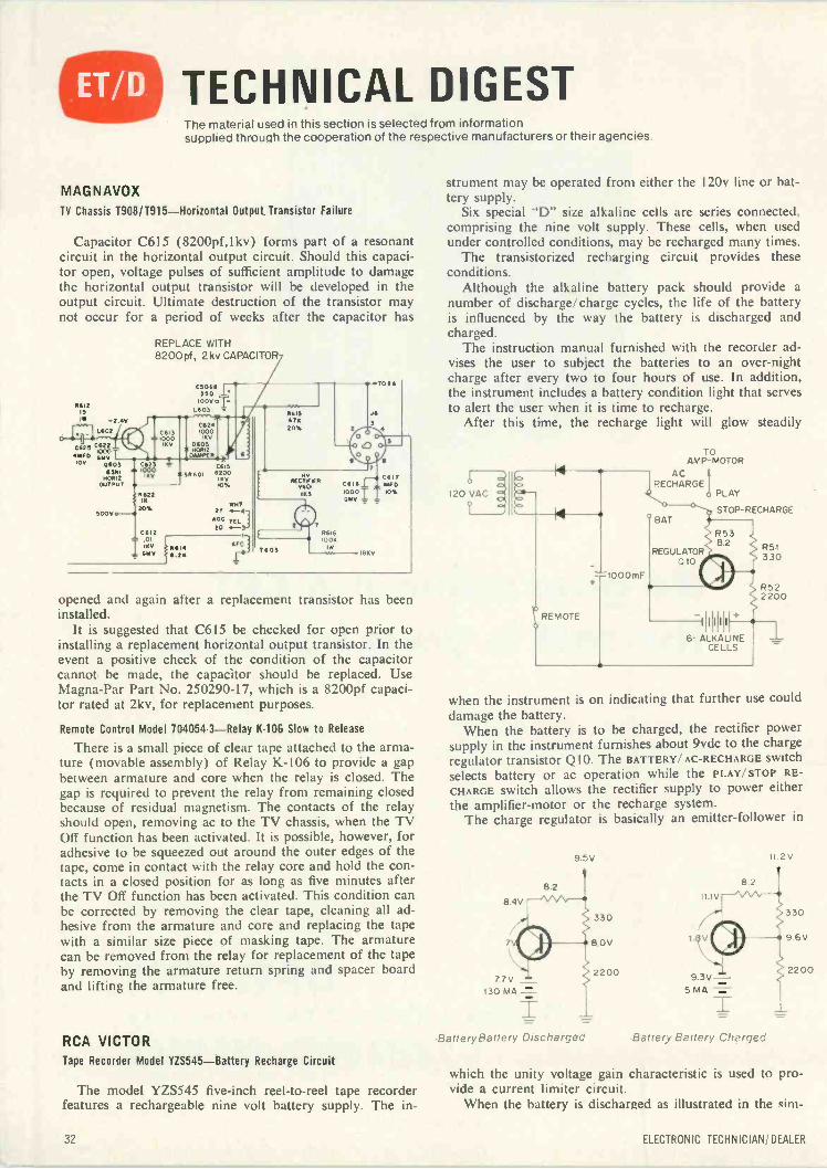
TECHNICAL DIGESTThe material used in this section is selected from informationsupplied through the cooperation of the respective manufacturers or their agencies.
MAGNAVOX
TV Chassis T908/T915-Horizontal Output Transistor Failure
Capacitor C615 (8200pf,lkv) forms part of a resonantcircuit in the horizontal output circuit. Should this capaci-tor open, voltage pulses of sufficient amplitude to damagethe horizontal output transistor will be developed in theoutput circuit. Ultimate destruction of the transistor maynot occur for a period of weeks after the capacitor has
-2.4vL602
cos C22ANTO v"°10v "V0603
sill,
HORI2OUTPUT
41.
REPLACE WITH8200pf, 2kv CAPACITOR
Cools r.770 1
WO/ oT-L1103
C6241000IRV
D601
PER
CSi3AA 1000
IRV
C6231000
RV
1522IR
SOOT 4-4 20%
C412- .01I WV
4411/
CMS 5601 4200
10/,0%
s
'NTOF -A0404
6.24
AF.1
ISIS47220%
T607
C61410007
86161004
TOSS
J4
opened and again after a replacement transistor has beeninstalled.
It is suggested that C615 be checked for open prior toinstalling a replacement horizontal output transistor. In theevent a positive check of the condition of the capacitorcannot be made, the capacitor should be replaced. UseMagna -Par Part No. 250290-17, which is a 8200pf capaci-tor rated at 2kv, for replacement purposes.
Remote Control Model 704054-3-Relay K-106 Slow to Release
There is a small piece of clear tape attached to the arma-ture (movable assembly) of Relay K-106 to provide a gapbetween armature and core when the relay is closed. Thegap is required to prevent the relay from remaining closedbecause of residual magnetism. The contacts of the relayshould open, removing ac to the TV chassis, when the TVOff function has been activated. It is possible, however, foradhesive to be squeezed out around the outer edges of thetape, come in contact with the relay core and hold the con-tacts in a closed position for as long as five minutes afterthe TV Off function has been activated. This condition canbe corrected by removing the clear tape, cleaning all ad-hesive from the armature and core and replacing the tapewith a similar size piece of masking tape. The armaturecan be removed from the relay for replacement of the tapeby removing the armature return spring and spacer boardand lifting the armature free.
RCA VICTORTape Recorder Model YZS545-Battery Recharge Circuit
The model YZS545 five -inch reel-to-reel tape recorderfeatures a rechargeable nine volt battery supply. The in-
strument may be operated from either the 120v line or bat-tery supply.
Six special AT size alkaline cells are series connected,comprising the nine volt supply. These cells, when usedunder controlled conditions, may be recharged many times.
The transistorized recharging circuit provides theseconditions.
Although the alkaline battery pack should provide anumber of discharge/charge cycles, the life of the batteryis influenced by the way the battery is discharged andcharged.
The instruction manual furnished with the recorder ad-vises the user to subject the batteries to an over -nightcharge after every two to four hours of use. In addition,the instrument includes a battery condition light that servesto alert the user when it is time to recharge.
After this time, the recharge light will glow steadily
120 VAC
I-.
REMOTE
TOAMP -MOTOR
ACRECHARGE
PLAY
STOP -RECHARGE
when the instrument is on indicating that further use coulddamage the battery.
When the battery is to be charged, the rectifier powersupply in the instrument furnishes about 9vdc to the chargeregulator transistor Q10. The BATTERY/AC-RECHARGE switchselects battery or ac operation while the PLAY/STOP RE-
CHARGE switch allows the rectifier supply to power eitherthe amplifier -motor or the recharge system.
The charge regulator is basically an emitter -follower in
8.4V
77V130 MA I
9.5 V
8.2
330
8.0 V
8211.1V
112V
330
i V 9.6V
2200 22009.3V -5 MA I
-BatteryBattery Discharged -Battery Battery Citericc
which the unity voltage gain characteristic is used to pro-vide a current limiter circuit.
When the battery is discharged as illustrated in the sim-
32 ELECTRONIC TECHNICIAN/DEALER
Untie your moneyWith"QT.' The QuickTurnover InventorySystem from RCA.
How much money do you have tied upin old, unsold replacement parts? If youhave more than your share of them,then it could be plenty.
RCA can change all that with a newQuick Turnover Inventory System-"QT"for short. It represents years of studyinginventory control.
Now you can have an inventoryof the fastest moving RCA parts,selected by RCA's computers. You'll havethe parts you need when you need them.You'll know when the supply is running low.And, if any parts are dropped from the"top -mover" list, simply return themthrough your "QT" distributor.
Talk to your RCA Parts Distributorabout putting in a "QT" Inventory System.The sooner you untie your moneythe sooner you'll be counting it.
Parts andAccessories

AT LAST ....solid statetriggered sweep, wide -band
at a price you can afford!
VOL 1
MUT Pe,
CAN:AMY NIC DYNAN
. kallIMEEIMEEEMEMEMIMIlb
LECTROTECHMODEL TO -50
POWER
,- EXTERNAL 00512 AMP
E TEL
cie
E AAAAAAHO/ eh
TEST SIGNALS
T Mt BASE
TOME;Div
10
EAT
TRIGGERING
41!...)S ENNUI,
MAN
TRIGGERIEVEI
TV
Made in U.S.A.
5" oscilloscope/vectorscopeTriggered Sweep: Easy to use. Positive sync results in absolutestability of patterns.
Solid State: For reliability and performance.Wide Band: 10 MHz --for increased use in all servicing, industrialand educational applications.
D.C. Amplifiers: Eliminates pattern bounce. Permits viewing A.C.signals and D.C. level simultaneously. Use as a sensitive D.C.voltmeter.plus . . . Calibrated vertical attenuator. Calibrated horizontaltime base. Automatic sync !node. TV sync selector. Vector-
scope input for color TV servicing. External horizontal amplifier. 60 cycle horizontal sweep (sine wave) with phasing control.Compatible with all sweep generators. Edge lit calibrated scale. All solid state (tube protected input).
ONE YEAR WARRANTY
TO-50-oscilloscope / vectorscope Net 329"
See your distributor or write Dept. ET -4
LECTROTECH, INC.4529 North Kedzie Avenue Chicago, Illinois 60625
... for more details circle 119 on Reader Service Card34
TECHNICAL DIGEST
plified schematic, its open -circuit terminal voltage will beabout 7.3v. When the recharge cycle is activated, the regu-lator circuit must supply a voltage that exceeds the batteryvoltage. Under these conditions the emitter voltage of Q10and the battery assumes a voltage of about 7.7v. Thiscauses a base voltage on Q10 of 8.0v (emitter voltage+.3v base -emitter barrier voltage =8.0v). Within thechosen values of R 1 and R2, sufficient base current is sup-plied to drive Q10 into saturation, thus the resistance ofthe saturated transistor and the 8.2fl resistor, R3, limit thecharging current to a safe value of about 130ma.
As the battery charges, its terminal voltage and the emit-ter voltage at Q10 increases causing the charging currentto decrease until the charged condition illustrated in theschematic is reached. The battery/emitter voltage of 9.3v,results in a base voltage of 9.6v, which is clamped at thispoint by the voltage divider action of R1 -R2. The reducedcharging current (now 5ma) allows the input voltage tothe regulator to increase to 11.2v; however, the base ofQI0 is clamped at 9.3v by R1 -R2. Consequently, the basecurrent diminishes and transistor conduction is reduceduntil the conditions are satisfied. Thus the battery chargecurrent, initially 130ma, has tapered to 5ma as the bat-tery assumes full charge.
GENERAL ELECTRICTape Player Models TA556/TD081-Servicing Hints
(1) These models were built using two (2) differentlength #4 metric screws for chassis hold down. Screws16mm in length were used in three of the four locations.A 14mm screw was used under the drive motor -right rearwhen viewing assembled unit from the front in normaloperating position.
Using a 16mm screw under the drive motor can resultin its interference with the motor case or even cause astalled motor.
Be certain to observe screw lengths and install shorterscrews underneath the drive motor.
(2) When servicing the preamplifier, it is important thatproper grounding be maintained between the chassis andthe circuit board ground.
Grounding is normally accomplished by the circuit boardretaining screw holding the circuit board ground in contactwith the chassis.
When this ground connection is broken, the ground re-turn for the head switching solenoid is through a channelindicator lamp. If the head switching button is depressedto activate the head switching solenoid, the high currentof the solenoid will burn the affected indicator lamp.
Be certain to use a jumper lead from circuit boardground to chassis when the circuit board retaining screwis removed.
(3) Many different performance problems can resultfrom oxide accumulations on the playback head and/orthe end of tape switch contacts.
Some of the problems are: (A) Dead Channel (B) Lowoutput on one or both channels (C) Loss of high frequen-cies (D) Hiss or Noise (E) Failure to automatically switchchannels.
If one of the previous problems occurs, be certain toclean switch and head. The use of alcohol and a cottontipped swab is recommended for cleaning.
ELECTRONIC TECHNICIAN/DEALER

New,
easy to installintercom system
Noreko Mastercom- M 30From small businesses to large industrialplants, MASTERCOM M 30 systems achievemaximum efficiency in handling internal com-munications. Instant person -to -person con-tact with push-button ease . . . and, thetelephone system is free to handle importantoutside calls.
Attractive Desk Top Units Push-buttonOperation True to Life Sound Quality Hands -free Answering Expandable System Handles up to 30 stations Simple One -cable Installation.
Your Norelco communication specialistwill be happy to demonstrate how aMASTERCOM M 30 system can improvecommunication efficiency . . . saving timeand money.
Clip and mail coupon for full informationand demonstration.
a
NorekoPHILIPS BUSINESS SYSTEMS, INC.A NOUN AMEtICAN PHILIPS COMPANY
100 East 42nd Street New York N. Y. 1001 ETD -470
Gentlemen:Please send rae full details on the NorelcoMastercom M 30.
Company Name
My Name
Street Address
City State Zip
DICTATICLf EQUIPMENT MA3TERCOM SYSTEMS FLECTLONBC PRINTING CALCULATORS OFFICE COMPUTORS... for more details cirde 123 on Reamer Service Card
APRIL 1970 35

Perfect fit:Econoline Van custom -designed to your job.CUSTOM -DESIGN YOUR VANYour job may call for a one -of -its -kind van. You can get it in an Econoline,and all from one place-from your Ford Dealer.
Sound impossible? Not for the man with better ideas. Your Ford Dealer cancustom -design the Econoline's interior into your kind of efficient workingspace, and it comes to you ready for work.
WIDE CHOICE OF MODULAR UNITSEconoline modular units (like those shown above) are the answer.Components include: racks, adjustable shelf units, drawer units, cabinets,bins (both padded and plain), padded trays, tote trays, hanging baskets,book compartments, storage boxes, partitions, padded siderails, paddedfloor, equipment holders, ladder racks, and many more.
These are not just parts and pieces, but a system of Econoline-engineeredunits designed to fit and work together. Constructed of heavy gauge steelwith gray enamel finish, they bolt to floor and/or body pillars to becomepermanent yet movable parts of the van. Traveling showcase or workshop-you name it and it's yours with the Ford Econoline.
BETTER IDEAS EASE YOUR WORKHowever you design your van, you have all of Econoline's basic better ideasgoing for you. Convenient outside front service center for quick -checkingengine and related parts. Driver "walk-through" for easy access to the loadcompartment. More clear floorspace by 23% than any other van. Wide51/2 -ft. stance for stability, yet a sharp 40 -ft. turning diameter formaneuverability. And, of course, exclusive Twin -I -Beam independent frontsuspension for great durability, easy handling, low maintenance, long tire life.
Because it is the one -of -its -kind van, you see more and more Econolineson all kinds of jobs. See how much more an Econoline Van can dofor you-see your Ford Dealer.
Radio, TV, Appliance Repair
General Utility
Laundry and Dry Cleaning
Vending Repair
FORD ECONOLINE VANS C... for more details circle 113 on Reader Service Card
36 ELECTRONIC TECHNICIAN/DEALER

ELECTRONIC TECHNICIAN DEALER APRIL 1970
TEKLAB REPORT
Craig Model 6304Color TV ReceiverAlthough most of the circuits in this
import TV are familiar, the AFT and part
of the chroma circuit may be co Musing so
we have outlined them in
this article.
According to the statistics of elec-tronic imports to this country, tele-vision sets may for the first time beleading the list of consumer importproducts. Until now radios held thelead with TV receivers bringing upa close second.
Many of these imports came overbearing American manufacturer'sbrand names. An increase in thenumber of TV imports means that
if you are not now servicing thesesets, you will most likely be calledupon for service in the future. A re-view of these sets will prove to behelpful.
We recently received the CraigModel 6304 color receiver which ismanufactured by Sanyo Electric Co.,LTD of Japan. Being the first im-port we evaluated, we found the cir-cuits to be quite standard except for
0
O
Craig Model 6304 color TV receiver.
APRIL 1970

Rear view of the re:eiver snowing service adjustments moulted on a circu t board.
Once the back cover am four b3Its on the tcttom panel are removed, the read -mapped circuitboard is exposed to make :ompo renova easier
a few minor circuit variations andadjustments which we will review.
The features on this receiver in-clude: AFT, Instant -On, slide typecolor controls, earphone jack, auto-matic degaussing and removablecontrast screen for viewing underbright lighting conditions.
All of the customers' controlswere found on the front panel foreasy accessibility. The volume, colorand tint are slide type controls witha rocker type on/off switch. Thespeaker is mounted on the frontpanel but seems a little muffled, pos-sibly because of the thick materialused for the speaker grill.
After removing nine screws onthe back cover and four screws onthe bottom panel, the completeetched circuit is exposed makingcomponent removal easier.
AFT CIRCUIT
The Automatic Fine Tuning(AFT) circuit shown in Fig. 1 usesa different method to prevent the os-cillator from locking on the accom-panying sound carrier. Negative volt-age is derived from the sync separa-tor, compared to the voltage from aB+ source, and applied to the anodeside of the AFT diode (varicap) inthe tuner (opposite side of the nor-mal AFT correction voltage). If theoscillator is momentarily too high infrequency and the AFT tries to lockin on the accompanying sound car-rier, the negative voltage derivedfrom the sync separator will becomelower than normal. The resultantvoltage applied to the diode be-comes slightly positive, therefore,pulling the oscillator back to a lowerfrequency to lock it on the videocarrier as desired. This correctionvoltage is opposite in polarity to thenormal AFT correction voltage as itis applied to the opposite end of theAFT diode. A diode, D26, is usedto clamp this resultant voltage to ap-proximately Ov in normal operationas it does not allow the resultantvoltage to rise in a negative direction.
LOW VOLTAGE POWER SUPPLYThe rectifiers and dropping resis-
tors are conveniently grouped to theleft and the rear of the chassis foreasy component replacement. Thetube filaments are divided into two
38 ELECTRONIC TECHNICIAN/DEALER

I Rom vw,u,6 43JND
BOARD 413,Po 1
1HR016',11
TO AFT SWITCHSW5 TERMINAL.
IAANU'
0801
0/102
1801All INPUTTRANSr
1111 1
111
11
,
, aTRYP21
,SC -r4If AMP
8 5v
C8031000 ".."
I8801
10K
S 88026E100
1
r 0805I 50
R8031500 c=
1802AFT 1ST C801
SET TRANS 15
88113
6200
881%
tt02
C8- IF
ftj T
0864
1803080154;46
AFT 211DTRANS
C809SI
18803 2505 16
58021541461595'
R8I0500K
3911301 R8II1K 6800
zw,r:7503'- 13DC AMP
LA125164148IS953
.., C812
0813680
DYL4
R81410K
R815I" nun /46 Y
C8I4loGe
144
C8I1000
-4'!?
5161;H.41,11141.6134;
,11
Fig. 1-Schematic diagram of the Automatic Fine Tuning circuit shows a correction voltage opposite in polarity to the normal AFT correction voltageand applied to the opposite end of the AFT diode.
6PC
STANDBYSWITCH 4
#931
P901INTER LOCK .._J1905
5979 40004
TWIT
1906HEATER TRANS
r+-.. 1,: 10 luNER HI
e_. c:i TI) TUNER "112CI 2; ,
501 s 6PC 2
MAIN UFI ONSWITCH 1904
02
C969 DS ?,?7i-1
Exe-r
C642220'-1mirs
C808
1000
C9/01000
892/226
RF 41
10
It
R928128
VIII6064A
6.1/c1,2p3 212
F901CIRCU T BRE K R i1030 firi3907 f LIN& CHOKE
4714 ft
1000 IoW")°°
190,661
C932 'cglis a
C10009."314:-
8979 89 30150A ?lit
0951 09woo ISM11 811401
C944. C915
010 .5315 romp,
89341506
D6 08 DS IMPOWER RECT
C94630911001-
89472;
r3x
OIL 47X R2?';91-.
1905AUTOMATICDEGAUSSING F F1935
P9074 P90;11
4II3 V119 8118 VI -.0 0111 0(14311S6A 6GH8 (Al 8381. 8108 -
x101/I.
8116
. .
V122 v121110W4A 8001 i2AZ 'A.
R931LOCK
Ofa
8946
Bin
R94H.7
RTHOR11
RUHLINES
II H6
/81-1;$1; '44°11:V101 011010/014 EAQ5A
EMI
8104 V105 810819 4"7 1120 4E3' 4E4/
(2WV;001570001512200
152 GI532200 2200
CI542200
Fig. 2-Schematic diagram of the low voltage power supply shows capacitor connection pointsfor voltage adjustments.
parallel strings, with a series diodein each string to achieve propervoltage to the filaments. The lowvoltage circuit is protected by a resettype of circuit breaker.
Before attempting to make anyadjustments on this chassis, espe-
cially after any one of capacitors,C931, C939 or C942, has been re-placed, make sure the voltage at testpoint "Bl" is between 370 and 385vline input voltage. The power supplyis shown in Fig. 2.
If the "Bl" voltage is too high,
disconnect C931C or disconnectboth C931C and C931B. If the "B"voltage is too low, connect C931Bor connect both C931B and C931C.
HIGH VOLTAGE SUPPLY
The high voltage regulation cir-cuit employs a 6BK4 shunt regu-lator tube which is not found onmany portable TV receivers. Thechassis also features pulse feedbackregulation for additional safety (seeFig. 4). Low voltage is applied tothe focus electrode connected to the270v., 385v or 650v taps for bestfocusing. The focus adjust tip is lo-cated on the top of the HV cage. Toobtain optimum picture width, re-connect the blue lead to either oneof the width adjust terminals on thedeflection yoke. The vertical center-ing adjustment is shown in Fig. 3.Raster position can be adjusted bythe vertical centering adjust tip onthe center of the chassis.
The horizontal efficiency and HVadjustments are quite standard withthe exception of the HV sub -regula-tion, which is not normally found ona portable.
CHRCoMA CIRCUITRY
Thr chroma circuitry containssix tunable adjustments in the band-pass amplifiers for proper amplitudeand phase response. It also has indi-vidual phase adjustments for eachR -Y, B -Y, and B -Y demodulator to
APRIL .1970 39

insure accurate phase relationships.Each demodulator has a balanceddiode detector with individual ad-justment for color noise cancellation.
According to the manufacturer, ifthis receiver should require service,just phone Western Union and askfor operator 25. On request she willgive you the name and location ofthe nearest Craig warranty servicestation. There are reportedly morethan 400 of these stations through-out the U.S.A.
VERTCAL CENTERING ADJuST TIP
A DOWNWARD SHIFT
B NEUTRAL
vAcTE AED RI110 `.YELLOW C UPWARD STITT
10 VERTOUTPUT TO RI TO (36 TO EI5
TRANS
Fig. 3-The vertical centering adjustment.
SPECIFICATIONSAntenna Input Impedance 300L1 balanced
Convergence Magnetic
Focus Electrostatic
Intermediate Frequencies:Picture IF Carrier Frequency 45.75 MHz
Sound IF Carrier Frequency 41.25 MHz
Color Sub -carrier Frequency 42.17 MHz
Picture Tube Approx. 115 sqin.
Power Input 120vac,60Hz
Power Rating 300w total
Sweep Deflection Magnetic
TV RF Frequency Range:All 12 VHF Channels 54MHz to 88MHz 174MHz to 216MHz
All UHF Channels 470MHz to 890MHz
Transistors 4
Diodes 30
Varistor 1
Thermistor 1
Tubes 22
1902VERT OUTPUTTRANS
a=1' C9091000
950 COOKi00,11 R901. '°'11
QO TO C010/000905 00, GENCE
1500 119100a 't1
V113 31JS6AHORIZ OUTPUT
DIDtiolo
00
I0 cowLGANc Y°0 5 b 1
TO CHROMA L DEFTBOARD N AND 0E11
(911 SOCrt 1 150 1
0 I
1104ROM/ OoTpulTRANS
V114 3AT2HI VOLT RECT
1ry8912
500
R 911 0011,CEBNIBT51)
`11f
sOnn
C95
0921 1000,o°,2 C9IS S7 0 02
10 F. AR CONTROLBOARD DO
0
VII6 I7DW4ADAMPER
0123II6CYP22
'PICTURE TUBE
p 911
IM
1,5 VI
V117 6BIL4ASHUNT REG
9902 Zo9°Avr'
SPARKGAP
CI05
BB O
(919 TO ROAR CONTROLSOO BOARD v.
ELM
1316NOR1/00101
ICUI:C"C Cl.:;j1'..7)11"t1
TO REAR CONTROLBOARD 'X'
TO REAR CoN I ROTBOARD r
Fig. 4-The HV regulation circuit employs a 6BK4 shunt regulator and feedback regulation.
40 ELECTRONIC TECHNICIAN DEALER

Part Two
Stereo Servicing With A Scopeby ROBERT L. GOODMAN
Part two and the concluding article in this timely service feature
includes dozens of handy troubleshooting hints geared to help youbecome more effective Jsing the generator -scope technique.
STAGE GAIN CHECKS Professionally triggered scopehave vertical amplifier gain controlswhich are calibrated in volts -per -centimeter or per division. The twovertical channels are identical so it'seasy to check one test point againstanother to compare the signal gainof each stage. The comparison meth-od is ideal for checking the gain ineach stage throughout the entire am-plifier and for checking the overallperformance of both channels. Thismethod is, of course, only valid ifone of the two channels is operatingcorrectly.
With this technique you canquickly isolate the trouble down tothe stage and possibly to the defec-tive component. As a final check ofthe amplifier, or if the original com-plaint was insufficient frequency re-sponse, the square -wave generatorfrequency can be tuned throughoutthe entire audio range for a frequen-cy response check. These checks canbe run at 1 kHz intervals with thedual -trace scope connected to eachchannel and both left and right sig-nals observed at the same time. Withthis method you can quickly observethe amplifier's overall frequency re-sponse.
When it comes to finding a caseof slight distortion in a high qualitycomponent Hi-Fi system for exam-ple, the triggered scope can be agreat troubleshooting time saver.
Let's put the scope on a Scottstereo amplifier brought into the shopby a critical listener for a frequencyresponse check out. The customertold us the amplifier did not sound asthough it was reproducing his stereo
1111111111111.M111P114111111111/11,1RIFAIALIMAINIA11111111111111111111111110M1111111111111111111111m111IPLIPINICIPZICK1111111111111111111111111111
11111111111111111
Fig. 1-The top waveforms indicate goodamplification at 8kHz while the bottom traceof the split -beam scope shows very little sig-
records like it did when the unit wasnew. The amplifier was connectedand a test record played. To a non-musical ear it sounded fair, but itseemed as though some of the highnotes were missing.
The split -beam scope was thenconnected to each channel's speak-er output and a sine -wave signal fedinto both amplifier input jacks. Thedial of the generator was tunedacross the audio spectrum with theleft channel indicating normal am-plification and frequency response.However, the right channel showedvery little amplification at about6kHz. Note the top wave -forms inFig. 1 indicate normal amplificationat 8kHz while the bottom trace ofthe split -beam scope shows very lit-tle signal amplification. The ScottModel 299F amplifier schematic isshown in Fig. 2.
The scope probes were moved astage at a time which showed tran-sistor, Q104 to be defective as itwould not amplify frequencies at 6or 8kHz. Other defective compo-nents can also cause this problem.
STEREO MULTIPLEX CHECKS
Ile Motorola AM -FM StereoIC350 chassis will be used for thesechecks. Shown in Fig. 3 is the AGCand stereo decoder system schemat-ic. A "flat pack chip" IC -2B is usedfor stereo decoding while the FMAGC voltage for the FM 2nd RFamplifier is obtained from the AGCamplifier transistor (05) collector.The FM 3rd IF signal is sampledthrough capacitor C 1 I. Diode E2converts the FM signal to a +dcvoltage. The voltage varies with thereceived signal strength and this dcvoltage then biases the NPN AGCamplifier.
A regulated + 12v is the ICsource voltage at pins 1 and 9. Pin 8receives a 4.7v bias from the samesource through resistor R33. Thefirst check should be for propervoltages at pin 1, 8 and 9. If theyare not correct, the IC or some oth-er component may be causing theproblem.
While looking at the schematic inFig. 3, we will follow the signal patharound the IC decoder stage. Mon-aural audio (L + R) enters the ICinput at pin 3 and is fed to the rightand left audio channels from pins11 and 12. Stereo information L -Rsidebands (23 to 53kHz) at the ICinput (pin 3) are decoded into au-dio: then added to the monauralsignal (L+ R) to reproduce the left(pin 11) and right (pin 12) stereoaudio signals. Each output channelfrom the IC is then bypassed to per-mit only audio to pass (30Hz-15kHz ) and frequencies above15kHz are attenuated. Use youroscilloscope when checking for
APRIL 1970 41
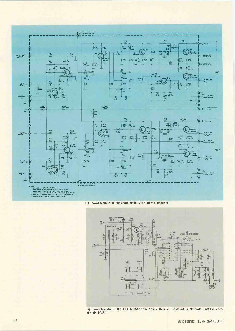
03
as. 4
CO311.07 2.114 >A
0-S00r.-C.04
00,00
Ltl
its
Ht
002
0/
"0
10111 400.1.35 0,00.0114 01.11L;140
Ay 401.0 04 0.001!.014.C111.1710" 1.00 10411101111 .0 0217 22 oC0.40.11 OC 100.1211011201110 00.220 20. 22/ 3.00.0,1111 01, .011
01411.1.1010.0.111.0 op0C C 1.0140000400 0.20/.2C20 4.4 St.. 11204
OP .4 ANCI Jp1.10.
0100,
1111)
00.1 C0111
'PT310101ESS
.0.1.00. 0001,0y40.0 P1.1..
00141
,5-
fa/
.11
`g:
*?;.1' aW
4
*zisv.,..
4-14-14 14 a. 44Olf OST
CIO
ROP/0
--to--c ,OR
x N NZ I
(11111.0
111
05
ton.
29
wn
1
5411'
Of I
15r'6
11001.1.
13 041NC012.20 22
"0 SA. OP000p Pon
0 t
roc. okouea COcotos cw
li
11.10
MARa In M
0.014114
-T.1)0
14
2Q7
01, I
400,42350,
A- I
101 4
"6
LEFT
JOY
10 WI. co1.2 ISP
0.0f
0210C0.0.104 Ca0
1716)/T
P0y. y
Fig. 2 -Schematic of the Scott Model 299F stereo amplifier.
fM
AOC
AM -AVC
fROIA DID 0--R-111 I ROMFM II A/A.DETRi
STEREO MUTE
RN ISA
059
Atti AU,3/1/ MAP
I SU
lyNINTA/tIlR
-T-MUTI
911
o o
1+
la 1 i 2.1.41.1,..,
FROM 17.10
.1.1
11,11 L
110/7
(V MT I. TT
01 °-10.110
11 1 112.
0511
RI) 4/0 E5$
czo IC -21 STEREO INDICATOR EIGHT
TIE IDES
'PM STEREO OE COO R ,>410C9Th10.13 'A.rte
1+1N
Ede F,T itieut.0
1.0
R)/ It
R36 11RAN
J
AUDIOOUTPUT
42
Fig. 3 -Schematic of the AGC Amplifier and Stereo Decoder employed in Motorola's AMFM stereochassis 1C350,
ELECTRONIC TECHNICIAN/DEALER

proper waveforms at pin numbers3, 11 and 12 of the chip if you arcnot receiving FM in stereo.
The 19kHz pilot transformer.L2 and the 38kHz stereo -carriertransformer, L1 are external to theIC. These are the only adjust-ments related to the IC. Connectthe scope to check for the properpilot carrier signals. During a stereobroadcast, pin 6 is grounded throughthe IC switch action to switch onthe stereo indicator light (E5B).The stereo information is blocked ifthe voltage at pin 4 drops below .9v.Since this voltage comes from therectified FM signal through resistorR38, this voltage will reduce withsignal strength. On weak, noisystereo stations, the voltage dropsbelow the .9v threshold point andall stereo information with noise isblocked but the monaural signal isnot affected.
To eliminate the normal "rushingor hissing" noise between FM sta-tions, the mute switch is depressed.If the mute voltage at pin 5 of theIC drops below a predeterminedlevel (approximately .9v) allsignals are blocked from passingthrough the IC.
With the mute switch depressed(on), the IC pin 5 is connected tothe FM rectified signal (JunctionC27, R24, R25). This rectified dcsignal varies with signal strength andbetween stations, the voltage dropsbelow the mute threshold ( .9v)and the IC is cut off with betweenstations and on undesirable weakstations. This action would be simi-lar to "squelch" used in two-wayradio receivers.
The mute feature is defeatedwhen the mute switch is released(off) and a fixed voltage (approxi-mately +1.1v) is connected to theIC audio mute input (pin 5)through resistor R409.
More stereo receivers will be us-ing solid-state circuitry in the nearfuture. One new chassis is the RCAModel RC1227 which was devel-oped by the c/COS (computercrafted) concept method. The 1stand 2nd IF amplifier stages are il-lustrated in Fig. 4 using this concept.Note the substrate Z201 which con-tains two transistors and many othercomponents. For circuit checks ap-
FM OR AM r egit 0201CONVERTER I
OUTPUT
1111
B+
B+
r
AM METER LDRIVE
T204-210
T203
FM
METER
47 I DRIVE- 3RD FMI IF AMP
I jlETECTOR
Fig. 4-Schematic of the 1st and 2nd amplifier stages employed in the RCA Model RC1227 ampli-fier employing the substrate 2201.
ply an RF signal (at the IF fre-quency) at pin 1 of the substrateand with a detector probe on yourscope, check for amplified IF signalat pin number 9. If the pin voltagesare found incorrect, you should re-place Z201.
COMPLEMENTARYSYMMETRY AMPLIFIERS
This amplifier design produces auniform frequency response through-out the audible frequency spectrum.Phase shift at low and high frequen-cies is reduced, while amplifier sta-bility and transient response is im-proved.
Complementary symmetry ampli-fication is not a new audio engineer-ing approach, but has been a gleamin the audio designer's eyes formany years. New approaches in de-sign for the past few years arematched-paired transistors, dualheat sinks, simplified circuits andapplication reports.
To enhance the output responseand to eliminate a major cause ofundesirable frequency discrimina-tion, these amplifiers are designedto take full advantage of transistorswithout the need for the driver andoutput transformer or the often
troublesome interstage coupling ca-pacitors. With the complementarydesign, transformers are eliminatedto achieve better performance atlower cost and smaller size.
The name "Complementary -Sym-metry Amplifier" is derived from theoutput transistor circuit configura-tion. In this circuit, an NPN and aPNP transistor are connected in se-ries to form the output circuit. Bothtransistors exhibit the same charac-teristic except for polarities.
In this circuit, a positive goingsignal increases the conduction ofthe NPN transistor while a negativegoing signal increases the conduc-tion of the PNP transistor. Thus, nophase inversion of the drive signal isrequired. The output transistorscompliment each other and producea symmetrical output signal.
Shown in Fig. 5 is a schematic ofa "complementary -symmetry" am-plifier. We will review some typicalcircuits to see how this functions.The 1st audio transistor, 06, is con-nected as an emitter follower (com-mon collector). Collector and basebias potentials are supplied fromterminal M2 which is also connectedto one side of the speakers. The oth-er speaker lead is connected to ter -
APRIL 1970 43
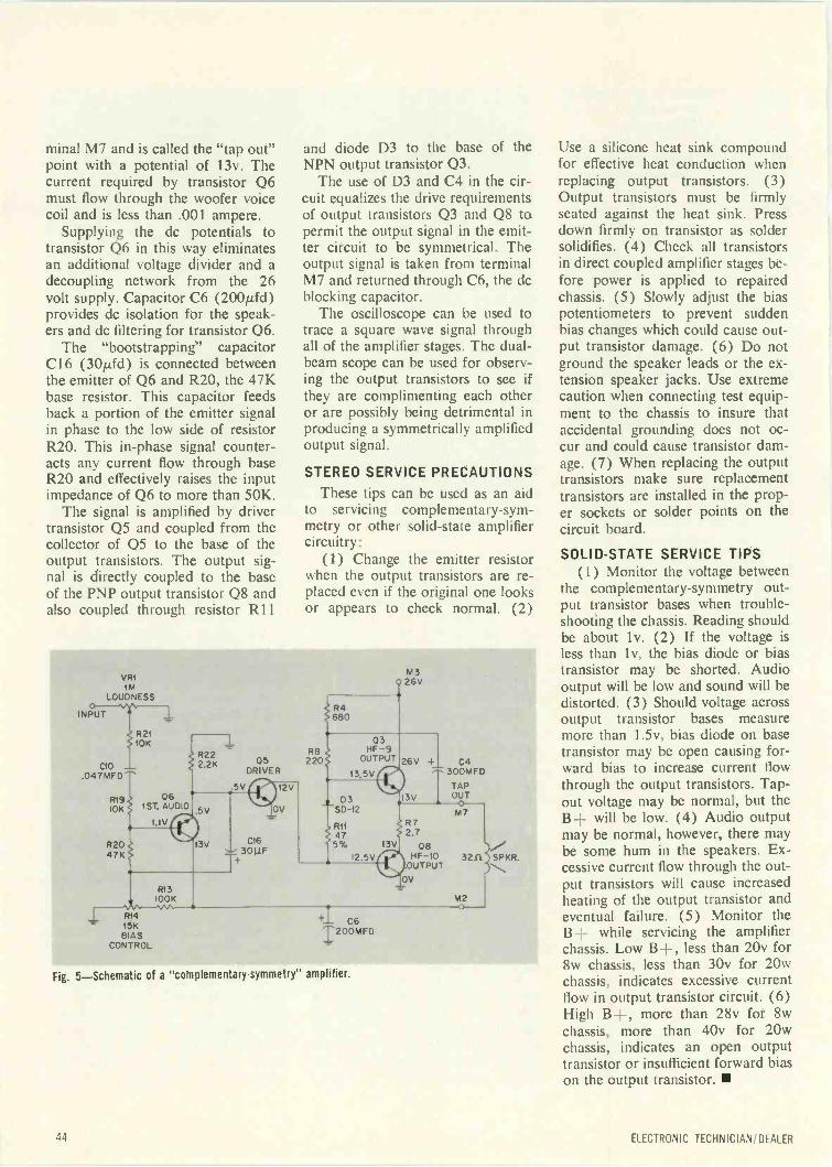
.047MFD
R19101(
minal M7 and is called the "tap out"point with a potential of 13v. Thecurrent required by transistor Q6must flow through the woofer voicecoil and is less than .001 ampere.
Supplying the dc potentials totransistor Q6 in this way eliminatesan additional voltage divider and adecoupling network from the 26volt supply. Capacitor C6 (200µfd)provides dc isolation for the speak-ers and dc filtering for transistor 06.
The "bootstrapping" capacitorC16 (30p,fd) is connected betweenthe emitter of Q6 and R20, the 47Kbase resistor. This capacitor feedsback a portion of the emitter signalin phase to the low side of resistorR20. This in -phase signal counter-acts any current flow through baseR20 and effectively raises the inputimpedance of Q6 to more than 50K.
The signal is amplified by drivertransistor 05 and coupled from thecollector of 05 to the base of theoutput transistors. The output sig-nal is directly coupled to the baseof the PNP output transistor Q8 andalso coupled through resistor R11
and diode D3 to the base of theNPN output transistor Q3.
The use of D3 and C4 in the cir-cuit equalizes the drive requirementsof output transistors Q3 and Q8 topermit the output signal in the emit-ter circuit to be symmetrical. Theoutput signal is taken from terminalM7 and returned through C6, the dcblocking capacitor.
The oscilloscope can be used totrace a square wave signal throughall of the amplifier stages. The dual -beam scope can be used for observ-ing the output transistors to see ifthey are complimenting each otheror are possibly being detrimental inproducing a symmetrically amplifiedoutput signal.
STEREO SERVICE PRECAUTIONS
These tips can be used as an aidto servicing complementary -sym-metry or other solid-state amplifiercircuitry:
(1) Change the emitter resistorwhen the output transistors are re-placed even if the original one looksor appears to check normal. (2)
VR1IM
LOUDNESS
INPUT
R2110K
R22C10 2.2K 05
DRIVER
1
061ST. AUDIO
1.IV
.5V
.5V
R20 13V47K
R415KBIAS
CONTROL
C16I.1
T+3°
12V
OV
R8220
M326V
R4680
03HF-9
OUTPUT
13.5V
03 jI3VSD -12
RII R7
47 2.75% 13V Q8
I2.5V HF-10OUTPUT
+- C6I200MFD
OV
26V + C4300MFD
TAPOUT0M7
32.0. SPKR...,
M2
Fig. 5-Schematic of a "complementary -symmetry" amplifier.
Use a silicone heat sink compoundfor effective heat conduction whenreplacing output transistors. (3)Output transistors must be firmlyseated against the heat sink. Pressdown firmly on transistor as soldersolidifies. (4) Check all transistorsin direct coupled amplifier stages be-fore power is applied to repairedchassis. (5) Slowly adjust the biaspotentiometers to prevent suddenbias changes which could cause out-put transistor damage. (6) Do notground the speaker leads or the ex-tension speaker jacks. Use extremecaution when connecting test equip-ment to the chassis to insure thataccidental grounding does not oc-cur and could cause transistor dam-age. (7) When replacing the outputtransistors make sure replacementtransistors are installed in the prop-er sockets or solder points on thecircuit board.
SOLID-STATE SERVICE TIPS(1) Monitor the voltage between
the complementary -symmetry out-put transistor bases when trouble-shooting the chassis. Reading shouldbe about lv. (2) If the voltage isless than lv, the bias diode or biastransistor may be shorted. Audiooutput will be low and sound will bedistorted. (3) Should voltage acrossoutput transistor bases measuremore than 1.5v, bias diode on basetransistor may be open causing for-ward bias to increase current flowthrough the output transistors. Tap -out voltage may be normal, but theB+ will be low. (4) Audio outputmay be normal, however, there maybe some hum in the speakers. Ex-cessive current flow through the out-put transistors will cause increasedheating of the output transistor andeventual failure. (5) Monitor theB+ while servicing the amplifierchassis. Low B+, less than 20v for8w chassis, less than 30v for 20wchassis, indicates excessive currentflow in output transistor circuit. (6)High B+, more than 28v for 8wchassis, more than 40v for 20wchassis, indicates an open outputtransistor or insufficient forward biason the output transistor.
44 ELECTRONIC TECHNICIAN' DEALER
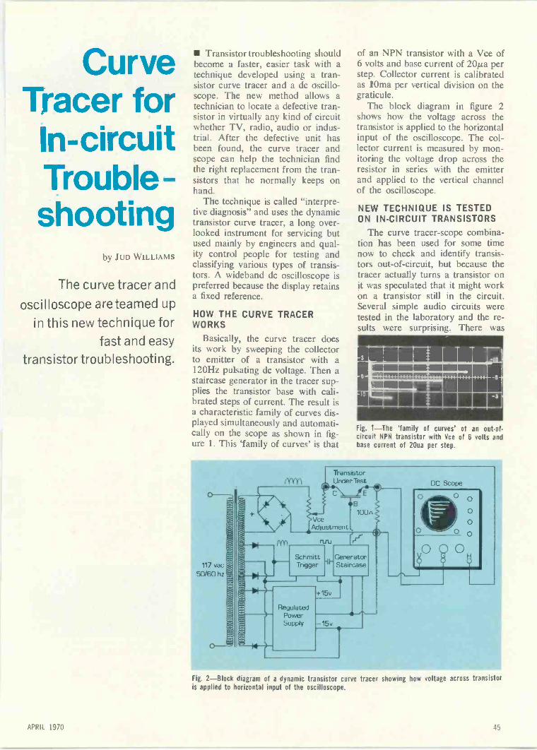
CurveTracer forIn -circuitTrouble-shooting
by .IUD WILLIAMS
The curve tracer and
oscilloscope are teamed up
in this new technique forfast and easy
transistor troubleshooting.
Transistor troubleshooting shouldbecome a faster, easier task with atechnique developed using a tran-sistor curve tracer and a dc oscillo-scope. The new method allows atechnician to locate a defective tran-sistor in virtually any kind of circuitwhether TV, radio, audio or indus-trial. After the defective unit hasbeen found, the curve tracer andscope can help the technician findthe right replacement from the tran-sistors that he normally keeps onhand.
The technique is called "interpre-tive diagnosis" and uses the dynamictransistor curve tracer, a long over-looked instrument for servicing butused mainly by engineers and qual-ity control people for testing andclassifying various types of transis-tors. A wideband dc oscilloscope ispreferred because the display retainsa fixed reference.
HOW THE CURVE TRACERWORKS
Basically, the curve tracer doesits work by sweeping the collectorto emitter of a transistor with a120Hz pulsating dc voltage. Then astaircase generator in the tracer sup-plies the transistor base with cali-brated steps of current. The result isa characteristic family of curves dis-played simultaneously and automati-cally on the scope as shown in fig-ure 1. This 'family of curves' is that
of an NPN transistor with a Vce of6 volts and base current of 20/23 perstep. Collector current is calibratedas lOma per vertical division on thegraticule.
The block diagram in figure 2shows how the voltage across thetransistor is applied to the horizontalinput of the oscilloscope. The col-lector current is measured by mon-itoring the voltage drop across theresistor in series with the emitterand applied to the vertical channelof the oscilloscope.
NEW TECHNIQUE IS TESTEDON IN -CIRCUIT TRANSISTORS
The curve tracer -scope combina-tion has been used for some timenow to check and identify transis-tors out -of -circuit, but because thetracer actually turns a transistor onit was speculated that it might workon a transistor still in the circuit.Several simple audio circuits weretested in the laboratory and the re-sults were surprising. There was
OE 11E111111mffemicamenii1111-011*61.11111111111
11112111111111111E111
Fig. 1-The 'family of curves' of an out-of-circui NPN transistor with Vce of 6 volts andbase :urrent of 2 Oua per step.
117 vac
50/60 hz
fr(Y)
IYY)
TransistorUnder Test
C
VceAdjustment
SchmittTrigger
GeneratorStaircase
RegulatedPowerSupply
15v
-15v
DC Scope
0
O
O
O
Fig. 2-Block diagram of a dynamic transistor curve trace- showing how voltage across transistoris applied to horizontal input of the oscilloscope.
APRIL H;(1

Mt' yeBEl
1111111WM11111111111111111111411111k
'1=1111111111111GI .206 1ST V1040 AMP
r
C;!70.14.orogaca.
_ _ _
-3
' 1111ONSSO1111Q20Z 2ND VIPS() IF
FIr
-.J
c
256.0600.05.110/10.001
4044I au mr,o' Zto oZlo Zoo
el650044,46C INC
no
4405010
10013004
_-_r- ------------
I I
-I le I ® ..""
[ 217111 C.7l-'..""
221.1211
ems216.1410
5.4 as
r.0.144/ WIMP
111111E.LIENNIIMI1111111=211111111111111111
-3 .
47,0304) NOISE GATE
strong evidence that the curve tracercould be used to determine whetherthe transistors in -circuit were 'good'or 'bad.'
A digital circuit was tested andthe results were again surprising.The big test came when the tech-nique was applied to the SylvaniaD14 color TV chassis. Every circuitwas tested with both good and badtransistors in place. Audio, RF andvideo circuits were all checked andeven with the loading effects of pe-
40
440050/k
XI;
VI"
50,41
LP.
1r00445 I
.aoo.
3 1
352.14ewe woo.,
7,11'
$xU I
405
111344.8 .8
111.11111111111M1.11111MINIMI11111111011111111
Q/.12Co Loit. KILLER
" V&aa ,oco raga.,
454
ripheral components the curve tracerwas able to differentiate betweengood and bad transistors.
As might be expected, the wave-forms of transistors while in a circuitare a far cry from those displayedwhen the curve tracer is used in theconventional manner. It was foundthat this doesn't matter because thewaveforms derived from this methodare very similar in character eventhough badly distorted. The vastmajority of transistor failures are
10.4.500 0115.444 411007r41
0500.00020/04 MCI 0608 4000.0604
0400 I445.5 0605400
Glee 41000008
Fig. 3-'Family of curves' created by Q100 in1st audio amplifier of the Sylvania D14 chassis.
catastrophic and in troubleshootingwe are only looking for either 'good'or 'defective' transistors.
46 ELECTRONIC TECHNICIAN/ DEALER
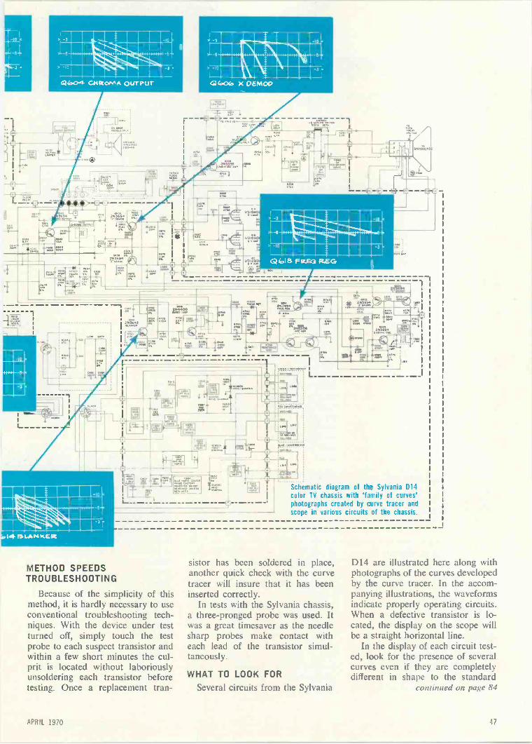
eft
3
-3 litO
MIINI1.111111Q04 CM Mr.01411 ouroPur
Cry
0'
Nam
.40SSA
L
I:3
OSA
OF-
gr.:21FL.
000
111111:1,111111111111111
111111A0Z1111111111111
14 MIA M IcEit
3.1 -3
-10
111,..1111111111111111111111011101111101111
11111111101111111111
MILMIN040(0 X DEM00
PON
66
V:47100
METHOD SPEEDSTROUBLESHOOTING
Because of the simplicity of thismethod, it is hardly necessary to useconventional troubleshooting tech-niques. With the device under testturned off, simply touch the testprobe to each suspect transistor andwithin a few short minutes the cul-prit is located without laboriouslyunsoldering each transistor beforetesting. Once a replacement tran-
66
1/) g/011
V. Mit
WLEIR111111111111111ILWOmiris1901111111161211011.111111111111111111111111111
4,16 F REG REG
11[606
'T "To ."11101 0006
r=i 00Mi IMO 101,
rt.ONSTED DO 000
fruso.
t r1341/n ue op
411.116001Xppm
,sanie convafte 1
Schematic diagram of the Sylvania D14color TV chassis with 'family of curves'photographs created by curve tracer andscope in various circuits of the chassis.
sistor has been soldered in place,another quick check with the curvetracer will insure that it has beeninserted correctly.
In tests with the Sylvania chassis,a three -pronged probe was used. Itwas a great timesaver as the needlesharp probes make contact witheach lead of the transistor simul-taneously.
WHAT TO LOOK FORSeveral circuits from the Sylvania
D14 are illustrated here along withphotographs of the curves developedby the curve tracer. In the accom-panying illustrations, the waveformsindicate properly operating circuits.When a defective transistor is lo-cated, the display on the scope willbe a straight horizontal line.
In the display of each circuit test-ed, look for the presence of severalcurves even if they are completelydifferent in shape to the standard
continued on page 84
APRIL 1970 47

From ScopeToVectorscopeby CHA LFS W JANECEK
Convert your scope to display the
vector pattern for servicing
color circuits without having to viewthe TV receiver screen.
Color television servicing can besimplified by the use of the vector -scope. A great amount of data in-volving color -circuit operation canbe obtained in one easy to readwaveform. The waveform obtainedon the vectorscope screen is a lissa-jous pattern since quadrature (90degree out -of -phase) information isimpressed simultaneously on theCRT's horizontal and vertical de-flection plates. The pattern is pro-duced by the sine wave outputs ofthe chroma demodulators when arainbow generator is connected tothe antenna terminals of a receiver.
Color reproduction is basically"Phase" interpretation by the colorcircuits in a receiver. The principleof operation of the Rainbow genera-tor is the production of a "linearphase sweep" which permits simul-taneous viewing on the receiver kine-scope of a number of color phaseswhich in turn enables the technicianto evaluate the operation of the re-ceiver.
The vectorscope's primary use isfor troubleshooting, spotting defec-tive diodes in the new tri-phase de-modulators, burst transformer and3.58MHz color oscillator alignmentas well as alignment of the 3.58MHztraps and high level demodulators.
The vectorscope technique can beput to practical use without buyinganother scope. Servicing color tele-vision receivers with automatic fre-quency control, automatic colorcontrol and similar circuits requirea good triggered or other qualityscope which is a very versatile piece
IR-Y) - VERT. FOR.DETECTOR RC. GND.
I B Y)
DETECTOR
Typical testtest setup using the oscilloscope todisplay vector patterns.
of test equipment and can also beused as a vectorscope.
All your service scope requires isa horizontal input terminal and amethod of connecting an incomingsignal to the horizontal amplifier toprovide a controlled horizontalsweep.
The procedure outlined uses onlyyour scope and it should performquite well as a vectorscope withoutmodifications. A special test harnessis not required, all you need are twopins to pierce the R -Y and B -Y de-tector leads (solid red and blue) tothe CRT. Connections can also bemade at the terminals on the receiv-er chassis. Insulation piercing typeclip leads can be purchased if de-sired.
SET-UP PROCEDURE
(1) Connect a color bar genera-tor to the antenna input terminals ofthe TV receiver. (2) Set the colorbar generator for a rainbow pattern.The signal from the generator iscrystal -controlled at a frequency of3,563,795Hz, about 15,750Hz lessthan the 3,579,545Hz subcarrier os-cillator in the color TV receiver. Thefrequency difference produces a sig-nal that will have a phase change offrom 0 to 360 degrees in the time ofa single horizontal scan of 53/As.When 360 degrees is divided by 30degrees, the result is 12. This is thenumber of color bars actually gen-erated. One color bar, however, isblanked by the generator and a sec-ond serves as the sync referenceburst and is emitted during the 10/As
blanking time of the TV receiver.Thus, only 10 bars are visible. Ifthe input signal is excessive, or ifthe color intensity control is ad-vanced too far from a normal signallevel, the vectorgram display maybecome flattened because of chromacircuit overload. (3) Set the verticalinput calibrator of the scope at 50volts per cm. If the signal input tothe vertical stage overdrives thescope, it may be necessary to use a10X probe and adjust the verticalattenuator for a pattern as in Fig.1. (4) Set the horizontal sweep se-lector of the scope to the EXT.HORIZ. input. (5) If grid drive isused, connect both the horizontaland vertical inputs of the scope tothe grid of the CRT's red gun. Ifcathode drive is used, connect boththe horizontal and vertical inputs ofthe scope to the cathode of the redgun. In the general low level andZenith high level demodulation sys-tems (called this because low levelmust be followed by amplifiers andhigh level is the final stage after theamplifiers), the vectorscope connec-tions are often made directly to thejunctions of the R -Y, B -Y outputs.Whereas in the tri-phase demodula-tion systems (either cathode or gridconnected), vectorscope connectionsmust be made at points where thesignal enters the picture tube for theleast loading and best isolation fromthe preceding semiconductors.
In the Motorola TS915 chassis,vectorscope connections would godirectly to the kinescope cathodes.(6) Adjust the horizontal gain con -
48 ELECTRONIC TECHNICIAN/DEALER
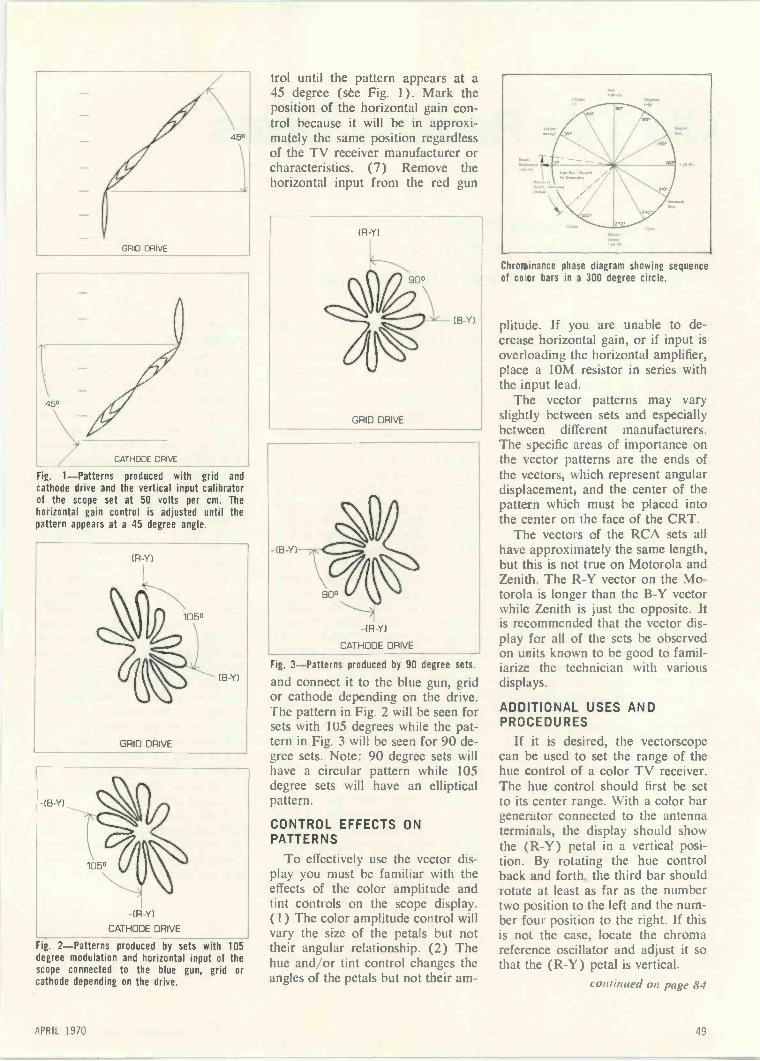
GRID DRIVE
45°
CATHODE DRIVE
Fig. 1-Patterns produced with grid andcathode drive and the vertical input calibratorof the scope set at 50 volts per cm. Thehorizontal gain control is adjusted until thepattern appears at a 45 degree angle.
fR-Y1
(B Y)
GRID DRIVE
-(F3 Y)
IR Yl
CATHODE DRIVE
Fig. 2-Patterns produced by sets with 105degree modulation and horizontal input of thescope connected to the blue gun, grid orcathode depending on the drive.
trol until the pattern appears at a45 degree (see Fig. 1). Mark theposition of the horizontal gain con-trol because it will be in approxi-mately the same position regardlessof the TV receiver manufacturer orcharacteristics. (7) Remove thehorizontal input from the red gun
(R Y)
GRID DRIVE
(B -Y1
-(B-Y)
-(R-Y1
CATHODE DRIVE
Fig. 3-Patterns produced by 90 degree sets.
and connect it to the blue gun, gridor cathode depending on the drive.The pattern in Fig. 2 will be seen forsets with 105 degrees while the pat-tern in Fig. 3 will be seen for 90 de-gree sets. Note: 90 degree sets willhave a circular pattern while 105degree sets will have an ellipticalpattern.
CONTROL EFFECTS ONPATTERNS
"I o effectively use the vector dis-play you must be familiar with theeffects of the color amplitude andtint controls on the scope display.(1) The color amplitude control willvary the size of the petals but nottheir angular relationship. (2) Thehue and/or tint control changes theangles of the petals but not their am-
Chrominance phase diagram showing sequenceof color bars in a 300 degree circle.
plitude. If you are unable to de-crease horizontal gain, or if input isoverloading the horizontal amplifier,place a IOM resistor in series withthe input lead.
The vector patterns may varyslightly between sets and especiallybetween different manufacturers.The specific areas of importance onthe vector patterns are the ends ofthe vectors, which represent angulardisplacement, and the center of thepattern which must be placed intothe center on the face of the CRT.
The vectors of the RCA sets allhave approximately the same length,but this is not true on Motorola andZenith. The R -Y vector on the Mo-torola is longer than the B -Y vectorwhile Zenith is just the opposite. Itis recommended that the vector dis-play for all of the sets be observedon units known to be good to famil-iarize the technician with variousdisplays.
ADDITIONAL USES ANDPROCEDURES
If it is desired, the vectorscopecan be used to set the range of thehue control of a color TV receiver.The hue control should first be setto its center range. With a color bargenerator connected to the antennaterminals, the display should showthe (R -Y) petal in a vertical posi-tion. By rotating the hue controlback and forth, the third bar shouldrotate at least as far as the numbertwo position to the left and the num-ber four position to the right. If thisis not the case, locate the chromareference oscillator and adjust it sothat the (R -Y) petal is vertical.
continued on page 84
APRII I 9;.0 49

Old TVs Reduce Taxesby LEON ROVICK
If your shop is cluttered with old TV chassis,
here's how you can get rid of them, save money
and perform a public service all at the same time.
In spite of the many complaintsby professional educators that ordi-nary citizens do not care to get in-volved in public education and itsproblems, especially vocational edu-cation, many citizens are provingthat they do care. Some of these arefraternal organizations who are as-sisting the radio and television repairclasses in vocational schools by col-lecting old radio and television re-ceivers from private individuals andlocal dealers. In a period of only twomonths, one organization in NewJersey was able to supply the Mid-dletown Vocational High Schoolwith 15 radios, 19 TV sets, 2 taperecorders and 4 record players. Thisis only a beginning in what theyhope will be a continuing program.
How does this involve the TVdealers? Nearly every radio and TVrepair shop has so-called "junk"cluttering up floor and shelf space.Every inch of space in your storecosts money. Holding onto this junkcuts into your profits. The questionis: how to dispose of this materialat no cost. One answer is to get aFraternal group interested in a proj-ect such as the one we just men-tioned. There are many such public-service groups around the country,some large and some small, but allinterested in serving. Many of thereaders of ELECTRONIC TECH-NICIAN are probably themselvesmembers of such groups. All that is
needed is the interest to ignite thefuse of action.
Not only will you get rid of thestuff cluttering your store, you canyourself also get actively involved inthe vocational program in your area.Dealers may not even be aware thatthere are vocational high schoolsin their area actively engaged intraining television and radio tech-nicians. Of course, you don't neces-sarily need the help of a fraternalgroup; you can deliver the sets di-rectly to the school. However, yourtime and that of your employees aswell as the expense of your truckcan cost a pretty penny. You cansave all this trouble and expensesimply by asking a fraternal group inyour area to sponsor the project.Moreover, since most fraternalgroups are publicity minded, yourfirm's name will be presented to thepublic in a favorable light at no ex-pense to yourself. What better ad-vertising can you get?
Further, your tax status maybenefit by deducting the equivalenteconomic value of the contributedmerchandise. Although the sets maybe junk to you, they do have marketvalue, however small it may seem.
Nearly every radio and TV re-pair shop in the nation can use moretechnicians. By getting personally in-volved in the program along with thefraternal group you can become ac-quainted with the school officials. By
cooperating with them everyonebenefits. Students are motivated tobetter learning if they know there isan opportunity for immediate em-ployment after graduation. And, byemploying these student technicianson a part-time basis, you can havea source of employees who can read-ily fit into your plans after gradua-tion. You are in effect training yourown help. In addition, your localvocational school officials can ex-plain the financial assistance offeredto tradespeople in cooperative edu-cation. But they can only do this ifyou make yourself known to them.
One final note-you will feel bet-ter emotionally if you know that thematerial you offer can in some wayserve a better purpose than simplyas ballast in a city dump. You canprobably recall when you werelearning principles of radio how youwished you had more material to ex-periment with that you didn't haveto buy. If by error a student destroysan item, that item has served its pur-pose; the student probably won'tmake the same mistake again. Andisn't it better for the potential tech-nician to make his mistakes inschool rather than on a customer'sset in your shop?
Think about the obvious advan-tages this plan offers to you; and youwill probably want to get involved,especially when you save money,time and trouble in the bargain.
50 ELECTRONIC TECHNICIAN DEALER
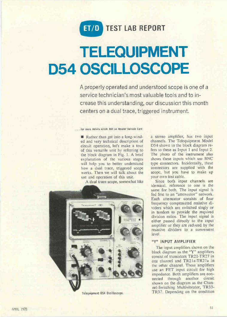
TEST LAB REPORT
TELEQUIPMENTD54 OSCILLOSCOPE
A properly operated and understood scope is one of a
service technician's most valuable tools and to in-
crease this understanding, our discussion this month
centers on a dual trace, triggered instrument.
. . . for more details circle 900 on Reader Service Card
Rather than get into a long-wind-ed and very technical description ofcircuit operation, let's make a tourof this versatile unit by referring tothe block diagram in Fig. 1. A briefexplanation of the various stageswill help you to better understandhow a dual trace, triggered scopeworks. Then we will talk about theuse and operation of this unit.
A dual trace scope, somewhat like
0.w "
Telequipment D54 Oscilloscope.
a stereo amplifier, has two inputchannels. The Telequipment ModelD54 shown in the block diagram re-fers to these as Input 1 and Input 2.The photo of the instrument alsoshows these inputs which use BNCtype connectors. Incidentally, theseconnectors are supplied with thescope, but you have to make upyour own test cable.
Since both input channels areidentical, reference to one is thesame for both. The input signal isfed first to an "attenuator" network.Each attenuator consists of fourfrequency compensated resistive di-viders which are switched singly orin tandem to provide the requireddivision ratios. The input signal iseither passed directly to the inputamplifier or they are reduced by theresistive dividers to a convenientlevel.
"Y" INPUT AMPLIFIERThe input amplifiers shown on the
block diagram as the "Y" amplifiersconsist of transistors TR21-TR27 inone channel and TR21a-TR27a inthe other channel. These amplifiersuse an FET input circuit for highimpedance. Both amplifiers are con-nected through another circuitshown on the diagram as the Chan-nel -Switching Multivibrator, TR33-TR37. Depending on the condition
APRIL 1970 51

MOD
PTPAr )
INPUT I CO. I.- AT TENUATOk
AT TENUATOR
50.--IKWII-P )--CAI.IBRATOR
41G
GN2
EXTX
T
/7'7'
W
Y INPUT
AMPLIFIER
TR2I--2l INCL
CHANNEL -SWITCHING
MULTIVIBRATOR
TR33 -37 INCL
INPUT
AMPLIFIER
TR2lo - 22, INCLL-
--1
, .
ALT
.- -CH2 Nl
t EXT!
INT
ALT. Li7r:Hi.-o
CH 2
OUT PUT
AMPLIFER
I R 28.2S 11.32
TRIGGER
T RI01-04
SWEEP -GATING
BITABLE
TRIOS 1106
"BLANKINGAMPLIFIER
TRIOS III 1115
SWEEP
GE NER ATOP
TRIO] 1 108
EXT 1
FIGURE A
PLFESA0.
__CRT 92
OUTPUT
AMPLIFIER
TRII2.113 1114
RTX PLATES
Fig. 1. Block diagram of the Telequipment D54 Dual Trace, Triggered Oscilloscope.
of this multivibrator, the output ofeither amplifier is fed to the "Y"output amplifier. When the scope isset to internal trigger, a portion ofeither amplifier's output may be fedto the trigger circuit.
CHANNEL -SWITCHINGMULTIVIBRATOR
As we indicated earlier, the chan-nel -switching multivibrator is used toprovide switching potentials to de-termine which of the input amplifierswill drive the output amplifier at anygiven time. In the alternate mode, agating pulse from the sweep -gatingbistable switches the multivibrator;each amplifier is switched on for ev-ery alternate sweep. In the choppedmode of operation, the multivibratorfree -runs and switches each ampli-fier on and off at intervals of about51a. Pulses are provided to blankthe CRT beam during switching.This provides automatic transientblanking in the chopped mode.
"Y" OUTPUT AMPLIFIERThis amplifier consists of tran-
sistors TR28, 29, 31 and 32. Theoutput signal from either input am-plifier is further amplified and feddirectly to the CRT "Y" plates. Aportion of this output may be fed tothe trigger circuit to enable thetimebase to be triggered by eachchannel's output alternately. Look-ing back at the two input channels,there are five possible channel -switching combinations dependingon the two channel push-buttonswitches and the CHOP -ALT slideswitch. The combinations are:Channel 1 on, 2 off; Channel 1 off,2 on; Channels 1 and 2 alternate;Channels 1 and 2 chopped; Chan-nels 1 and 2 off.
The block designated as CALI-BRATOR is used to provide a50mv P -P squarewave at the powerline frequency as a means of check-ing the "Y" amplifier and for time-base calibration.
TRIGGER CIRCUITGoing down the diagram, we
see the block labeled TRIGGER,TR101-TR104. The purpose of thiscircuit is to provide pulses of suit-able amplitude and polarity to trig-ger the sweep -gating bistable frominternally or externally derivedwaveforms. The bases of the inputtransistors in this circuit are fed withtriggering signals from either thevertical amplifier for internal opera-tion, or from the EXT TRIG ter-minal for external operation depend-ing on the position of switch S101.This push-button switch is labeledon the front panel as EXT TRIGand INT.
SWEEP -GATING BISTABLE
This circuit consists of transistorsTR105-TR106. Its function is todetermine the start and finish ofeach sweep. Suitable voltages areapplied to the unblanking amplifierand channel -switching multivibrator
52 ELECTRONIC TECHNICIAN/DEALER

TECHNICAL DATA
VERTICAL AMPLIFIER and ATTENUATOR
Operating modes
3dB bandwidth - d.c. coupleda.c. coupled
10 to 90% risetimeCalibrated deflection sensitivity ± 5%
Variable gain control provides continuous coveragebetween ranges
Maximum input (via 400V capacitor a.c. coupled)Input impedance approx.
HORIZONTAL SYSTEM
TriggerInternal - Minimum deflection
Source
External - a.c. coupledInput impedance approx.
Useful bandwidth approx.AutomaticTrigger levelHF
Sweep generatorCalibrated sweep speeds 5%
Variable control provides continuous coverage
between rangesMaximum speed range approx
Horizontal amplifier3dB bandwidth -- --10 to 90% risetimeDeflection sensitivity approx.Input impedance approx.Maximum input
CATHODE RAY TUBE
Display areaOverall post -deflection accelerationAvailable phosphorsExternal intensity modulation
CouplingSignal for cut-off at average brillianceTime constant
FRONT PANEL OUTPUTS
Calibrator - supply frequencySweep sawtooth
AmplitudeMinimum load
Probe test
POWER REQUIREMENTS
Voltage
FrequencyConsumption
PHYSICAL DATA
Approximate overall dimensions and weight:High Wide
24.5cm 21cm
93 in 81,bin
CoolingApproximate ambient temperature limits:
Operating
Chanrel 1 onlyChannel 2 onlyAlternate - Channel switching during
flybackChopped - Chandel switching at
100kHz approx. Automaticblanking
d.c. 10MHz2Hz - 10MHz35ns nominal10mV - 50V/cm (12 1-2-5 steps)
400Vp1M!,! « 40 pF
2mmChannel 1Channel 2Alternate1.5 Vp-p to - 15V
100k!! & 10pF
50Hz - 1MHz10Hz - 3MHz1MHz - 10MHz or better
200ns - 2s/cm (22 1-2-5 steps)
4Ons 5s/cm
d.c. - 1MHz350ns nominal600mV - 3V/cm1M!! & 30 pF400Vp
6 x 10cm4kVP31 (standard), P7 & P11
a.c. to first grid-20Vp approx.
10ms approx.
50mVp-a ±2%
1-35V approx. d.c.-coupled30k!!500mV approx.
100 - 125V in 5V steps200 - 250V in 10V steps48 - 440Hz32VA approx.
Deep44.5cm171/2in
Weight9 25kg201/lb
Convection
-15 to +40°C + 5 to +104°F-25 to +70°C -13 to +158°F
Non -operating

Interior view showing component and circuit board mountings.
to provide beam-unblanking duringthe sweep and channel -switching atthe end of each sweep in the alter-nate mode.
SWEEP GENERATOR
The sweep generator provides asawtooth waveform which is passedto the "X" output amplifier and afront panel terminal. In the externalX condition, the stage operates asthe X input amplifier. The "X" out-put amplifier, shown on the blockdiagram as consisting of TR112,113 and 114, amplifies the sweepsawtooth or the external X signaland feeds it in push-pull to the CRT"X" plates.
UNBLANKING AMPLIFIERIn this circuit, the beam-unblank-
ing pulses from the sweep -gatingbistable are amplified and applied toa CRT electrode to deflect the beamon to the tube phosphor for the dur-ation of a sweep and when theTIME/CM switch is set to EXT X.Pulses are then fed from the chan-nel -switching multivibrator to blankthe beam when the multivibratot'changes state in the chopped mode.
POWER SUPPLY ANDCRT CIRCUITS
We mention the power supply be-cause it uses a power transformerwhich has two primary windings andtwo secondary windings. The trans-
former primaries are connected inparallel for operation from 100 to125vac and in series for operationfrom 200 to 250 vac. So this unitwill operate on almost any ac linepower available. A plug is providedon the rear panel which is insertedin the correct set of contacts for theline voltage being used. The tappedsecondary of the transformer prO-vides other operating voltages exceptfor the CRT filament which is sup-plied from a separate 6.3 volt wind-ing floated at about -1kV.
The CRT used in this instrumentis a 5in. flat -faced rectangular unitoperating at 4kV accelerating volt-age. The CRT also has provision forexternal modulation through a ZMOD connector at the rear of theinstrument. Intensity modulation isac -coupled to the first CRT grid.
OPERATION
The operation of a dual tracescope is much like any other goodscope except that it has two inputsand provides two traces on thescreen. The obvious advantage ofsuch a unit is in its ability to allowthe operator to compare two simul-taneous waveforms. Since the D54is also a triggered scope, it has theadvantage of being stable-thewaveforms will not jump around onthe screen and you can accuratelydetermine the value of the waveformbeing viewed. As we indicated ear-lier, triggering in a dual trace scopeis accomplished by signals from thevertical amplifiers or from an ex-ternal source. This instrument al-lows for triggering from either theTV field (frame) or from line pulses.There is also a + and - push-but-ton to provide triggering from thepositive or negative slope of the in-put waveform.
Some of the more common ap-plications of a dual trace, triggeredscope in servicing are to trouble-shoot stereo amplifiers, FM multi-plex circuits, power supplies, colorTV and pulse circuits. Naturally adual trace, triggered scope costs abit more than a scope which doesnot have these functions. But if youare thinking of making a scope partof your equipment expansion, a unitof this type might be worth consid-eration.
54ELECTRONIC TECHNICIAN/DEALER

1.
10 -inch -longer useable loadspace.
5. 6.Power steering,
optional.Power brakes,
optional.
Model shown is127"wheelbaseTradesman 3(X)
2.Independent front suspension and
31/2 -inch -longer wheelbasefor better ride and handling.
7.
7 -inch -larger hood opening.Easier battery,
dipstick, and radiatorservicing.
3.
345 pounds more payload.Up to 3930 pounds o
Tradesman 300.
8.
Engine coveris 4 inches lower, 10 inches shorter.
Makes it easy for driver to reach cargo area.
Engine can be removed quickly Two -stage door checks11.
Bumper jack Wider doors and door stepscan I !li full load Posi-latch doors.n Trade.,Inaii 100 and 200 111,1htz tor e,r,rr rr
Automatic transmission,
INTRODUCING THE ALL -NEW 1971
9.Integral
air conditioning,optional.
4.Hidden cargo step.
Cargo doors easier to open.Won't stick or collect
ice or snow.
10.Car -style
instrument panel.All controls within easy reach
...kkl111111111)1111111111
V-Inon
Independent suspensionand standard track 18
Biggerstandard engines.
198 Six. 318 V8
DODGE STRONGBOXThe big, new Tradesman Van that outdoes
the better idea people 31 ways.
20 21
26 -gallon gas tank. Two -inch -wider seatswithsgii,r,-or, '
Full foam paddingmeans, nr r rdr
Badge Truths41.
CHRYSLERMOTORS CORPORATION
Full -width sun visors.Larger windshield
wiper pattern.
Extra rust protection
Wind tunnel body shape
Doors adjustable three ways
Front seat does not blockthe cargo door entrance.
High-level air intake
Fiber -glass engine cover
Ashtray on engine cover.
Heater located inengine compartment
ter
APRIL 1970. for more details circle 111 on Reader Service Card
55
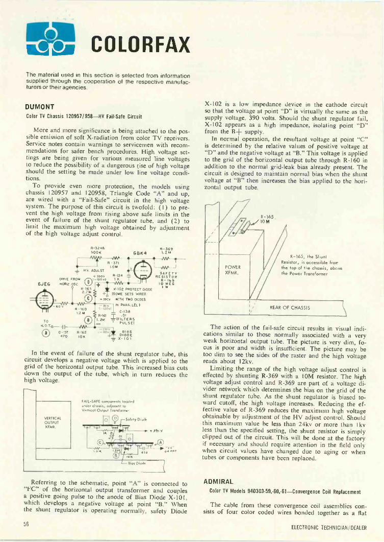
COLORFAXThe material used in this section is selected from informationsupplied through the cooperation of the respective manufac-turers or their agencies.
DUMONT
Color TV Chassis 120957/958-HV Fail -Safe Circuit
More and more significance is being attached to the pos-sible emission of soft X-radiation from color TV receivers.Service notes contain warnings to servicemen with recom-mendations for safer bench procedures. High voltage set-tings are being given for various measured line voltagesto reduce the possibility of a dangerous rise of high voltageshould the setting be made under low line voltage condi-tions.
To provide even more protection, the models usingchassis 120957 and 120958, Triangle Code "A" and up,are wired with a "Fail -Safe" circuit in the high voltagesystem. The purpose of this circuit is twofold: (1) to pre-vent the high voltage from rising above safe limits in theevent of failure of the shunt regulator tube, and (2) tolimit the maximum high voltage obtained by adjustmentof the high voltage adjust control.
6JE6
R-3246500 K 6BK4
R - 371I.01.4
H.V. ADJUST
4-3900CANE FROM
O(-1000)HORt2 OSC.
R-1632.21A
-GOO
TO11 0
0 C -137470
R -1601.2 M
R -I24
1.2R- 36 9
M
IP MO
- -OW J
X-102 PROTECT DIODE(SOME SETS WIRED
3900 WITH TWO DIODES
- 350 14 PARALLEL )
C-138R -I61 -r .01
1-2M ='..(FILTERSPULSE)
2300R -I62 t t300II 8IAS
DI+ ODE10KX - I 0 I
- 12001
SAFETYRESISTOR
R-16510 MEG
1 W
In the event of failure of the shunt regulator tube, thiscircuit develops a negative voltage which is applied to thegrid of the horizontal output tube. This increased bias cutsdown the output of the tube, which in turn reduces thehigh voltage.
VERTICALOUTPUTXFMR.
FAIL-SAFE components locatedunder chassis, adjacent toVertical Output Transform,
-51 Cdi Safety Diode
r
4 o,0
Bias Diode
+340V
aw rler
Referring to the schematic, point "A" is connected to"FC" of the horizontal output transformer and couplesa positive going pulse to the anode of Bias Diode X-101,which develops a negative voltage at point "B." Whenthe shunt regulator is operating normally, safety Diode
X-102 is a low impedance device in the cathode circuitso that the voltage at point "D" is virtually the same as thesupply voltage. 390 volts. Should the shunt regulator fail,X-IO2 appears as a high impedance, isolating point "D"from the B+ supply.
In normal operation, the resultant voltage at point "C"is determined by the relative values of positive voltage at"D" and the negative voltage at "B." This voltage is appliedto the grid of the horizontal output tube through R-160 inaddition to the normal grid -leak bias already present. Thecircuit is designed to maintain normal bias when the shuntvoltage at "B" then increases the bias applied to the hori-zontal output tube.
R-165 .
A/10 M
R-165, the ShuntResistor, is accessible fromthe top of the chassis, abovethe Power Transformer
The action of the fail-safe circuit results in visual indi-cations similar to those normally associated with a veryweak horizontal output tube. The picture is very dim, fo-cus is poor and width is insufficient. The picture may betoo dim to see the sides of the raster and the high voltagereads about 12kv.
Limiting the range of the high voltage adjust control iseffected by shunting R-369 with a 10M resistor. The highvoltage adjust control and R-369 are part of a voltage di-vider network which determines the bias on the grid of theshunt regulator tube. As the shunt regulator is biased to-ward cutoff, the high voltage increases. Reducing the ef-fective value of R-369 reduces the maximum high voltageobtainable by adjustment of the HV adjust control. Shouldthis maximum value be less than 24kv or more than 1 kvless than the specified setting, the shunt resistor is simplyclipped out of the circuit. This will be done at the factoryif necessary and should require attention in the field onlywhen circuit values have changed due to aging or whentubes or components have been replaced.
ADMIRAL
Color TV Models 940303-59,-60,-61-Convergence Coil Replacement
The cable from these convergence coil assemblies con-sists of four color coded wires bonded together as a flat
56ELECTRONIC TECHNICIAN/ DEALER

stack these upagainst the others ...
iiIIiIIlIIIIIIIi9 Or 460
Al
for just the price of other sweep -marker generators,you can get a bench full of Heathkit) color test gear
Stack These Up Against The Others ... a high performanceSweep -Marker Generator, an accurate Color Bar -Pattern Generator,a versatile VTVM and a rugged, dependable Scope ... all for only$347.40* ... $50 less than the cost of other sweep -marker gener-ators alone. At Heath, we still believe that you should be able toget a stack of gear without spending a pile of money.
QI Heathkit IG-57A Solid -State Sweep -Marker Gener-ator ... $135.00'. 15 crystal controlled markers for color band-pass, TV sound, IF, picture & sound carriers for channels 4 & 10,FM IF ... new Video Sweep Modulation allows injection ofchroma-sweep directly into IF amplifiers or thru antenna terminals
. two built-in variable bias supplies ... 400 Hz modulated orCW output of any individual marker... exclusive external attenuator... stable, linear sweep signals for the five most used frequencyranges ... complete scope matching controls ... quick disconnectBNC connectors ... complete with all probes, test leads & termi-nated cables. 14 lbs. Assembled IGW-57A, 11 lbs. ... $199.00'
02 Heathkit IG-28 Solid -State Color Bar -Pattern Gen-erator ... $79.95'. Produces 12 patterns plus clear raster ...dots, cross -hatch, vertical & horizontal bars, color bars and shading
Compare Heathkit performance and value
NEWFREE 1970 CATALOG!Now with more kits. more color.Fully describes these along withover 300 kits for stereo; hi-fi.color TV, electronic organs, gui-tar amplifiers, amateur radio.marine. educational, CB. home& hobby. Mail coupon or writeHeath Company. Benton Harbor,Michigan 49022
bars in 9x9 or exclusive 3x3 display ... all solid-state usingcomputer -type integrated circuitry ... variable front -panel tuningfor channels 2 thru 6 . . variable front -panel positive and negativevideo output ... front panel negative going sync output ... built-ingun shorting circuit with lead piercing connectors ... switchablecrystal -controlled sound carrier. 8 lbs. Assembled IGW-28, 8 lbs.... 5114.95'
03 Heathkit IM -28 "Service Bench" VTVM $39.95'Measures RMS DC & AC Volts from 1.5 - 1500 ... AC P -P from4 - 4000 V ... resistance from 0.1 ohm - 1000 megohmseasy -to -read 6" meter... 10 -turn vernier controls for zero & ohms
. single test probe for all measurements ... 4-1 dB 25 Hz -1 MHz response. 7 lbs. Assembled IMW-28, 7 lbs. ... $59.95'In The Heathkit 10-18 5" Wide -Band Scope ... $92.50'5 MHz band -width ... five sweep ranges from 10 Hz - 500 kHz
+ or - internal, line or external snyc ... two extra, presetablesweep positions ... front panel 1 V P -P reference ... Z-axis input
. retrace blanking ... 0-135' phasing control ... frequency -compensated vertical attenuation. 24 lbs. Assembled 10W-18,23 lbs.... $149.95'
.. you'll see the others just don't stack up.
HEATH COMPANY, Dept. 24-4Benton Harbor, Michigan 49022
0 Enclosed is $
Please send model (s)0 Please send FREE Heathkit Catalog. Please send Credit Application.
Name
w.w...r Y-6 KIT
a Schlumbetoef company
plus Shipp ng.
Address
City Stale Zip*Mail order prices; F.O.B. factory. Prces & specifications subject to change without notice. TE-220
--1
. for more details circle 116 on Reader Service Card
APRI 57

Only Admiralgives youthe Super-Britecolorpicture tubewith built-incustomersatisfaction.
The exclusiveAdmiral3-year warranty.
Now Admiral offers all new Super -Brice color picture tubeswith the exclusive Admiral 3 -year warranty. This industryexclusive provides your customers with maximum satis-faction.
Every Admiral Super-Brite color picture tube hasAdmiral -engineered thermal compensation for unexcelledcolor purity and the newest phosphors that give your cus-tomers clear, bright, sharp color pictures.
Here's another Admiral exclusive: In model 25SP22(25AP22), our engineers have developed a vacuum de-posited thin -metallic film on the inside of the envelope toassure trouble -free operation and longer life.
Admiral Super-Brite service color picture tubes aren'trebuilts. They're 100% brand new. From Admiral, pro-ducers of more rectangular color picture tube sizes thananybody in the world-the only one with the 3 -year pro-tection you asked for.
AdmiMork of Quality
Admiral Corporation warrants this picture tube to be free from defectsin material or workmanship for 3 years after date of sale to the consumer.Admiral's obligation is limited to supplying a suitable replacement picturetube. This warranty is effective if the picture tube is registered withAdmiral within 10 days after date of sale to the consumer.
... for more details circle 101 on Reader Service Card
COLORFAX
conductor cable. The inside wires of the cable are con-nected to the vertical coils; the outside wires are connectedto the horizontal coils.
The color coding of the replacement may differ fromthat of the original either in color or sequence or both. Wesuggest that you compare the replacement with the originalbefore you remove the original. If they differ in any way,ignore the color coding when wiring the replacement.Connect the wires in the same physical sequence as theoriginal (be sure that you view both original and replace-ment from the same side).
GENERAL ELECTRICVoltage Dependent Resistors (VDR-Varistors) and TemperatureDependent Resistors (TDR-Thermistors)
In modern television design, devices are being used incritical circuits to automatically adjust circuit parametersto maintain constant performance regardless of variablessuch as line voltage changes, component aging and ther-mal effects.
Two of these devices which are quite popular today arethe VDR and TDR. Both are non-linear resistors. Thismeans that doubling the voltage across them does not dou-ble the current through them. These non-linear resistors canbe manufactured with either a positive or negative coeffi-cient. A negative coefficient device is one whose resistancewill decrease with an increase of the electrical or environ-mental conditions to which it is sensitive.
Checking a non-linear resistor requires some knowledgeof how it functions. A simple ohmmeter check will not pro-vide an accurate test. Most non-linear resistors can bechecked in operational circuits using simple voltage mea-surements and observing circuit performance. The absoluteohmic value is not important-the device's reaction to en-vironmental change is what must be determined.
continued on page 60
58ELECTRONIC TECHNICIAN/DEALER

How tospend less time
sellingmore
batteries
ROArl "TOWER OF POWN BATTERI
RCA's new "Tower of Power" merchandiser doesalmost everything for you but make change. It holdsover 10 dozen batteries-in just 10 inches of counterspace!
Its gravity -feed means automatic stock rotation. Itrotates at the touch of a finger (great for impulsesales). It tells your salesmen what they need to know-battery data and prices. And it has individual chan-nels for each of the popular sizes, 9 -Volt, "D", "C",and "AA" cells.
Another great feature. If you're concerned aboutpilferage, the "Tower of Power" can be set up so only
your sales clerks can remove the batteries!Designed to display any or all of the top 10 types
that cover 9 -out -of -10 customer needs...Zinc Car-bon, Alkaline, or Mercury.
Think round, think today. Get the "Tower of Power"and you'll sell more batteries without even trying.Contact your RCA Battery Distributor for completedetails or write RCA Electronic Components, Com-mercial Engineering, Section D205N, Harrison, N. J.
07029.
APRIL 1970 59
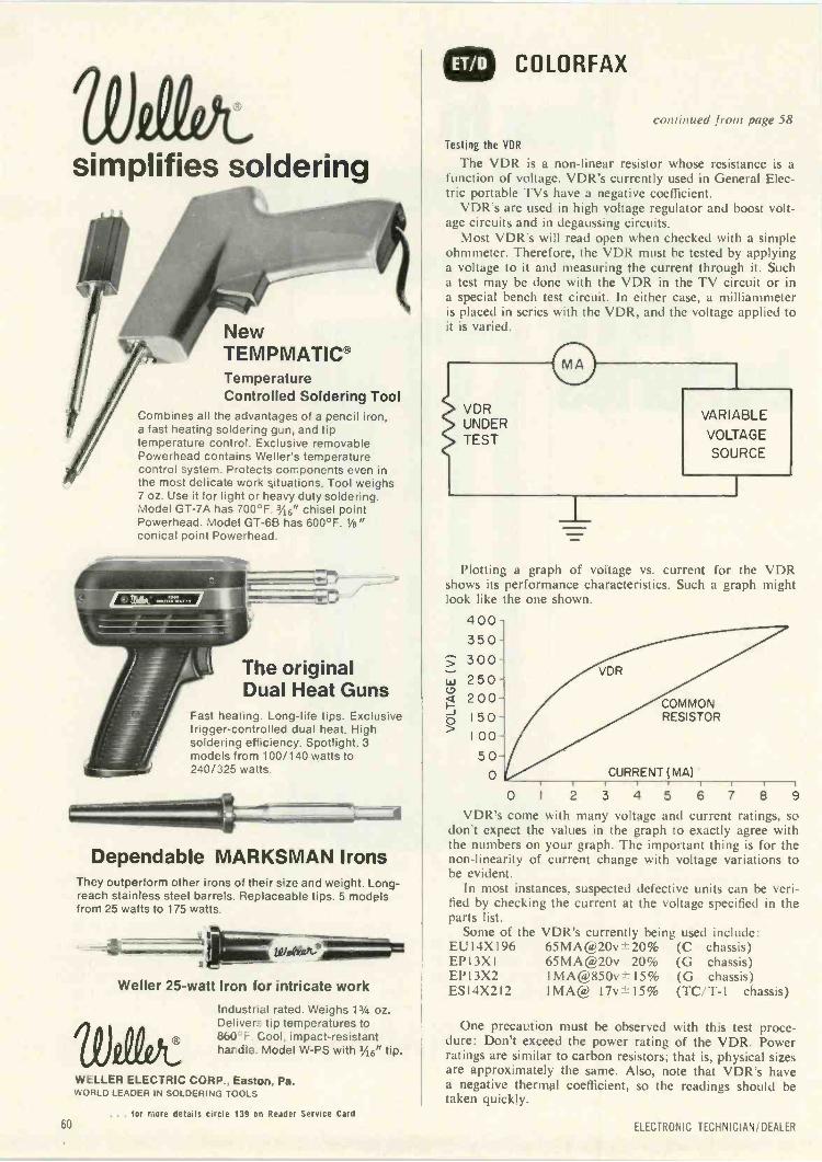
simplifies soldering
NewTEMPMATICTemperatureControlled Soldering Tool
Combines all the advantages of a pencil iron,a fast heating soldering gun, and tiptemperature control. Exclusive removablePowerhead contains Weller's temperaturecontrol system. Protects components even inthe most delicate work situations. Tool weighs7 oz. Use it for light or heavy duty soldering.Model GT-7A has 700°F. 3'16" chisel pointPowerhead. Model GT-6B has 600°F. 1/8"conical point Powerhead.
The originalDual Heat Guns
Fast heating. Long -life tips. Exclusivetrigger -controlled dual heat. Highsoldering efficiency. Spotlight. 3models from 100/140 watts to240/325 watts.
===4--"----"'Dependable MARKSMANMARKSMAN Irons
They outperform other irons of their size and weight. Long -reach stainless steel barrels. Replaceable tips. 5 modelsfrom 25 watts to 175 watts.
4 witeest-7
Weller 25 -watt Iron for intricate work
Industrial rated. Weighs 13/4 oz.Delivers tip temperatures to860`t-. Cool, impact -resistanthandle. Model W -PS with %6" tip.
WELLER ELECTRIC CORP., Easton, Pa.WORLD LEADER IN SOLDERING TOOLS
COLORFAX
continued from page 58
Testing the VDR
The VDR is a non-linear resistor whose resistance is afunction of voltage. VDR's currently used in General Elec-tric portable TVs have a negative coefficient.
VDR's are used in high voltage regulator and boost volt-age circuits and in degaussing circuits.
Most VDR's will read open when checked with a simpleohmmeter. Therefore, the VDR must be tested by applyinga voltage to it and measuring the current through it. Sucha test may be done with the VDR in the TV circuit or ina special bench test circuit. In either case, a milliammeteris placed in series with the VDR, and the voltage applied toit is varied.
VDRUNDERTEST
VARIABLE
VOLTAGE
SOURCE
Plotting a graph of voltage vs. current for the VDRshows its performance characteristics. Such a graph mightlook like the one shown.
4 003 5 0
3 0 0
2 5 0 -
2 0 0 -
1 5 0
1 00
5 0-0
VDR
COMMONRESISTOR
CURRENT ( MA)
0 I 2 3 4 5 6
VDR's come with many voltage and current ratings, sodon't expect the values in the graph to exactly agree withthe numbers on your graph. The important thing is for thenon -linearity of current change with voltage variations tobe evident.
In most instances, suspected defective units can be veri-fied by checking the current at the voltage specified in theparts list.
Some of the VDR's currently being used include:EUI4XI96 65MAOL)20v±-20% (C chassis)EP13X1 65MA(s)20v 20% (G chassis)EP' 3X2 IMA6i)850v 15% (G chassis)ES14X212 1MA(22 17v±-15% (TC/T-1 chassis)
One precaution must be observed with this test proce-dure: Don't exceed the power rating of the VDR. Powerratings are similar to carbon resistors; that is, physical sizesare approximately the same. Also, note that VDR's havea negative thermal coefficient, so the readings should betaken quickly.
60. . . for more details circle 139 on Reader Service Card
ELECTRONIC TECHNICIAN/DEALER

THE FIRST IN -CIRCUIT TESTTO TELL A GOOD TRANSISTOR
FROM A BAD ONE.WITH NO IFS, ANDS OR BUTS.
Inside every transistor is a message you wantto get at: whether the transistor is good or bad.
We've come up with a way to let thetransistor tell you. For dead -certain, withoutever taking the transistor out of the circuit.(In fact the circuit isn't even on.)
Our way is the transistor curve tracer you seeabove. It sweeps a transistor with pulses ofDC voltage. And presto, the transistorstarts talking.
You get the message on an oscilloscope.If the transistor is good you see a family
of curves; if it's kerflooey, a single vertical ordrooping line appears; and if the transistoris open, the scope will show you a singlehorizontal line.
Another thing.Transistor manufacturers make lots of
essentially identical transistors. But eachmanufacturer uses different numbers, so youdon't know the transistors are identical.
Our transistor curve tracer can tell you thattoo. So you don't have to buy all those identicaltransistors; instead you can build up aninventory of universal replacement types.
It's all so simple, we don't know whysomebody didn't think of it before. All we knowis, nobody did.
The dynamic transistor curve tracer.$120 at your local distrHutor's.
Good transistor. Shorted transistor.
JUD WILLIAMSBox 335, Long Valley, N.J. 07853. (201) 876-4376
... for more details circle 140 on Reader Service Card
Rommassmsel
()pen transistor.
APRIL 1970

DEALER SHOWCASEFor adddronal intormation on productsnumners on Reader Service Caro Request., t,andied
COAXIAL RELAY 704
Low-cost andcompact size
Announced is the availability of thetype 77 coaxial relay fitted with type"F" connectors. This low-cost 7512
4 DOW KEY
ti
SPDT relay, which is particularlyadapted to CATV service, occupies aspace of approximately 2 x 2 x % in.The relay is available in a number ofactuating coil voltages, from 6 to115v, ac and dc. Dow -Key.
TWO -STATION INTERCOM 705
Personal communi-cation at a low price
A low-cost, battery -operated, twostation intercom, blister packed for re-tail merchandising, is introduced. The
Model BLST-20 "Small -Talk" two -station intercom is a two transistorsystem. Compact and lightweight,both stations are suitable for wall,table and desk installation. The unitconsists of a master with an On/Offvolume control and a non -private re-mote which permits hands free op-eration at the remote station. A beep -tone signals when someone at the re-mote wishes to talk. Both stations areequipped with a push -to -talk button.
Both stations are housed in ruggedcabinets finished in high impact sty-rene. The intercom is simple to installand comes complete with a 50ft plug -terminated interconnecting cable. Listprice less than $12. Fanon.
706
CASSETTE CLASSROOM SYSTEM
Designed and constructedfor educational use
An electronic classroom system thattakes advantage of the popular tapecassette is introduced. The new In-
structomatic Cassette System providesfull dual -channel operation with acomplete line of in -booth and remotestudent recorders, console and rackmounted lesson sources. All can becustom combined to perform in lan-guage lab, stenographic, library, ortotal audio tutorial applications. Auniversal record/playback head whichaccepts all standard monaural andstereo cassettes is used on all decks toguarantee compatibility with recordersoutside the system. Each cassette re-corder is designed and constructedspecifically for educational use. A five -finger push-button control sequencegives the student or instructor one -hand operation of all necessary rec-ord/playback modes, including skip -forward and skip -back review. Three -motor drive, all -electronic circuitry,etched aluminum faceplate, and asimple cassette load mechanism arefeatured. A low cost, lesson mediathat snaps quickly and positively intothe deck with no need for tape thread-ing is available. The cassette is lessthan half the size of conventional reelsor cartridges. It stores easily and canbe carried in a student's pocket. Thelow cost cassette recorders are com-mercially available to students forhomework purposes, and high-speedduplicating machinery is available toschools to allow easy reproduction of
many student cassettes from a singlemaster. Instructomatic.
TELEPHONE AMPLIFIER 707
Powered by fourpenlight batteries
A battery -powered, solid-state tele-phone amplifier, which provides "no -hands" phone conversations betweenindividuals or groups, is announced.The telephone amplifier set (ModelTA 100) consists of an amplifier andspeaker unit. The instrument is pow-ered by four penlight batteries anddoes not require wiring or installation.Another feature of the amplifier set isthat it can be moved from one tele-phone location to another. Both thespeaker and amplifier units are housedin plastic housings, hich are con-temporary in design and in white andharvest beige color. Operation of theamplifier set is simple. After the bat-teries have been inserted, the tele-phone handset is placed in the "well"at the front of the amplifier unit. Theuser talks toward the mouthpiece ofthe telephone as it rests in the ampli-
fier unit. His voice is picked up, enabl-ing the listener to hear him or a groupof persons as if they were speaking di-rectly into the mouthpiece of thephone. The voice of the party on theother end of the line is amplifiedthrough the speaker unit. Volume ofthe speaker can be increased or de-creased by turning the volume controlknob on the amplifier unit. After a callis completed, the amplifier shuts offautomatically when the phone is liftedoff the device and hung up. List price$17.95. RCA.
continued on page 64
ELECTRONIC TECHNICIAN/DEALER62
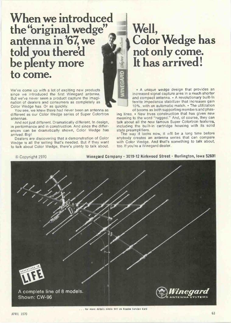
When we introducedthe "original wedge"antenna in '67, wetold you there'dbe plenty moreto come.We've come up with a lot of exciting new productssince we introduced the first Winegard antenna.But we've never seen a product capture the imagi-nation of dealers and consumers as completely asColor Wedge has. Or as quickly.
You see, we knew there had never been an antenna asdifferent as our Color Wedge series of Super Colortronantennas.
And not just different. Dramatically different. In design,in performance and in construction. And since the differ-ences can be dramatically shown, Color Wedge hasarrived. Big!
Dealers are discovering that a demonstration of ColorWedge is all the selling that's needed. But if they wantto talk about Color Wedge, there's plenty to talk about.
t Copyright 1970
Well,Color Wedge hasnot only come.It has arrived!
A unique wedge design that provides anincreased signal capture area in a much shorte-and compact artenna. A revolutionary built-inferrite impedance stabilizer that increases gain10%, with an automatic match. The utilizationof booms as both! supporting members and phas-
ing lines. New truss construction that has given newmeaning to the word "rugged." And, of course, they cantalk about all the now famous Super Colortron features,including the built-in cartridge housing with its solidstate preamplifiers.
The way it looks now, it will be a long time beforeanybody creates an antenna series that can comparewith Color Wedge. And that's something to talk about,too. If you're a Winegard Dealer.
Winegard Company 3019-12 Kirkwood Street Burlington, Iowa 52601
A complete line of 8 models.Shown: CW-96
. . . tor more details circle 141 on Reader Service Card
APRIL 1970 63

DEALER SHOWCASE
continued Irvin /rage 62
SLIDE SYNCHRONIZED 708CASSETTE RECORDER
Built-in slide/filmstripsynchronizer
A heavy-duty, ac -powered cassetterecorder with a built-in slide/filmstripsynchronizer is introduced. The basic
mechanism of the audio-visual record-er consists of a full-sized, heavy fly-wheel, a large -diameter, sturdy cap-
stan and a long -life ac motor. Theslide synchronization unit, Model 2550,uses a 60Hz signal to activate thetripping mechanism and minimizescross -talk between the narration andthe sync signal tracks. The narrationand sync signal can be recorded eitherindependently or simultaneously. Ei-ther can be changed or re-recordedwithout erasing the other. All operat-ing controls are conveniently located,color -coded for fast, intuitive actionand safety interlocked to prevent ac-cidental erasure of tapes. An automat-ic record level control assures high-quality recordings without need formanual monitoring. The basic per-formance specifications claimed forthe unit are: Frequency response of 50to 8,000 Hz, wow and flutter of lessthan 0.25 percent, signal-to-noise ratioof more than 46dB, and a 1 Ow ampli-fier. They are equipped with perma-nently attached three -wire groundedpower cords. Suggested list price$299.95. 3M.
HAM BAND RECEIVER 709Moderately priced 80-10meter receiver
A moderately priced 80-10 meterHam band receiver is introduced. TheModel A-2516 receiver features a me-
e foryourlff new
solid state
instant -on
MIGHTY MITE ICE Now faster than ever. Instant -on action with all solid state
FET circuitry ---no waiting for warm-up. New push-button operation speeds up every test --saves
you valuable time. New 13th socket checks still more tubes --now over 3000
including foreign. New hi -style case--vinyl-clad and brushed steel. A profes-
sional instrument designed for professionals.At your distributor now, only $99.50
E=Nc =tomU ,7t NANCE 1,Ju
426 SOUTH WESTGATE DRIVE. ADDISON. ILLINOIS 60101
chanical filter to provide highly selec-tive AM, CW and SSB reception onall Ham bands between 3.5 and 29.7
MHz. This includes 80, 40, 20, 15 and10 meters. It also receives the WWVfrequency standard signal on 10MHz.The dual conversion receiver featuresa crystal -controlled first local oscillatorand a solid-state VFO-type second os-cillator reportedly having negligiblefrequency drift. The VFO circuit hasoutput terminals for use as a trans-mitter VFO. Remote control terminalson the receiver allow easy switching tostandby operation. A calibrated S -meter aids tuning and provides an ac-curate signal strength indication. Themechanical IF filter provides a 1.5kHzbandwidth at 6dB down, 6kHz at60dB down. Sensitivity is 1 .5p,v forIOdB signal-to-noise ratio at 14MHz.Image ratio and IF rejection are bet-ter than 40dB at I4MHz. The circuitemploys 7 tubes, 2 transistors and 5diodes. An anti -backlash double -geartuning dial provides accurate, direct -reading down to I kHz. Smooth 28:1dial speed ratio facilitates precise tun-ing. Receiver is priced at $169.95.Allied.
BATTERY DISPLAYS 710
Attractive displayin woodgrain design
A series of impulse -buying counterdisplays covering a variety of batteriesfor all applications is offered. Thecompact displays are attractive, wood-
grained designed to catch the custom-er's eye. Free revolving racks are alsoavailable with offer 72-G (general as-sortment); 7 -OR (for transistor ra-dios), and 71-P (for photo equip-ment). Mallory.
... for more details circle 131 on Reader Service Card64
ELECTRONIC TECHNICIAN/DEALER
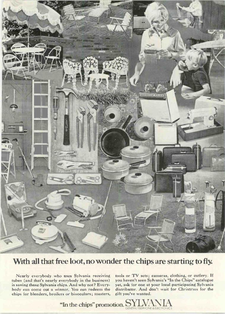
With all that free loot, no wonder the chips are starting to fly.
Nearly everybody who uses Sylvania receivingtubes (and that's nearly everybody in the business)is saving those Sylvania chips. And why not? Every-body can come out a winner. You can redeem thechips for blenders, broilers or binoculars; toasters,
tools or TV sets; cameras, clothing, or cutlery. Ifyou haven't seen Sylvania's "In the Chips" catalogueyet, ask for one at your local participating Sylvaniadistributor. And don't wait for Christmas for thegift you've wanted.
"In the chips" promotion. SYLVAN IAGENERAL ELEPHONE ELI-CTRONICS

Electronics Reference Databook RCA Color TV Service Manual Electronic Circuit DesignHandbook
IIT
ELECTRONICS
REFERENCE
DATABOOK
s.tvis 7.t,f.
I
This new book is muchmore than a simple col-lection of tables, formu-las, graphs, equations,etc. In addition to theabundance of helpful in-formation given, it pro-vides specific guidancein the use of data. Nu-merous problems asso-ciated with every levelof interest-from elec-tronics theory (formu-las, laws) to measure-ments, tests, and circuit
design work-are covered. In so doing, the au-thor explains how to use the data (from this orother volumes) for purposes other than thoselisted. Covers Electronics Theory, Use of J Op-erator, Exponential and Other Tables. Attenua-tors and Equalizers, Filter Design, PracticalComponent Design and Application, Tube andSemiconductor Circuit Design and Operation.and Transmission Lines. 224 pps., over 100illus.. plus 45 tables. Hardbound.List Price 57.95 Order No. 488
A brand-new full sizemanual, covering 23RCA Color chassis. In-cludes complete sche-matic diagrams for 12chassis, from the CTC-12 to the CTC40 all -transistor model. Herein one compact, handymanual is everythingyou need to quickly andcompetently repair ensRCA color set-fromthe CTC12 to the 1960all -transistor CTC40.
Encompasses both general and specific trouble-shot:ding data applicable to all RCA chassis.The text delves into each section (Video, chro-ma, vertical, horizontal, etc.), and points outspecific problems as well as general servicingprocedures. Troubleshooting tips on each chas-sis, including circuit changes and factory mod-ifications, are covered. While this material isrelated directly to RCA sets, much of it is ap-plicable to other sets patterned after RCA de-signs. 176 pps., 8% x 11, plus 36 -page sche-matic foldout section. Over 175 illus.List Price 57.95 Order No. 496
New Third Edition-Abrand-new, enlargededition of the ever pop-ular circuit designer's"cookbook," now con-taining over 600 provencircuits, for all types offunctions, selected fromthousands on the basisof originality and prac-tical application. Nowyou can have, at yourfingertips, this careful-ly -planned referencesource of tried and
tested circuits. Selected from thousands sub-mitted by distinguished engineers, these"thought -starters" are a collection of originalcircuits selected on the basis of their useful-ness. This detailed compilation of practical de-sign data is the answer to the need for an or-ganized gathering of proved circuits . . . bothbasic and advanced designs that can easilyserve as stepping stones to almost any kindof circuit you might want to build. 384 pps.,19 big sections, over 600 illus., 81 x 11".List Price $17.95 Order No. 7-101
Installing & ServicingHome Audio Systems
lnrtdlrr & Servictni
HOME
AUDIO S
At last, a long -neededUP-TO-DATE guide-book on home audiosystems - your "pass-port" to the lucrativefield of audio equipmentservicing, includingsales and installation.Included in the compre-hensive content aretechnical descriptions ofthe latest audio and hi-fi equipment, accompa-nied in each case by ser-vicing data. The author
describes all the various types of units, illus-trates the typical circuits used, then tells howto look for troubles. You'll receive scores ofpractical "tips." plus troubleshooting shortcuts.After an introduction to audio, and a discussionof test instruments needed, the author gets intoAM and FM tunersfincluding stereo -multiplex),preamps and amplifiers, tape recorders andplayers, mobile radios and tape players, andautomatic record players. 266 pps., over 160illus., 12 Chapters. Hardbound.List Price 57.95 Order No. 505
How To Fix Transistor Radios &Printed Circuits
Here it is! Just off th,press-a completely up-dated, revised edition ofLeonard Lane's best-selling classic on tran-sistor radio repair. Inaddition to extensivienrichment of the firstedition, the authorbrings FETs, zener di-odes, FM radios - ifact, everything relatedto the current state ofthe art-into the pic-ture. Here's the perfect
reference and guide for electronic technicianswho need to understand and repair semicon-ductor circuits efficiently. For those interestedin transistor physics, fundamentals are em-phasized in the first two chapters. The real"meat" begins in Chapter 3 which will thor-oughly familiarize you with amplifier funda-mentals, basic circuit configurations, biasing,FETs, JFETs, and IGFETs. The next twochapters will acquaint you with RF and IFamplifiers. 256 pps., over 150 illus.. 12 Chapters.List Price 57.95
Hon
TRANSISTOR
RADIOS &
Priole0
CircuilsMI8111111 italiIT Malt tltl
'it
Order No. 504
Working with Semiconductors
A BRAND-NEW work-ing guidebook to semi-conductor circuit oper-ation of value to tech-nicians and others whowork with solid-stateequipment. The won-derful aspect of thisbook is that you canreally develop a thor-ough understanding ofsemiconductors - andactually enjoy doingit! In striking contrastto the usual textbook
approach, this up-to-the-minute volume avoidsdry, theoretical mathematical explanation-ittells you simply how and why things work ...backed up by large, clear expository illustra-tions. More advanced circuits covered are:transistor oscillators, multivibrators, Eccles -Jordan and Schmitt trigger circuits, crystal -controlled generators, counters, power supplies,high -frequency circuits, field-effect transistors,unijunction transistors, tunnel diodes, SCRs,etc. 224 pps.. over 185 illus., 15 Chapters.List Price 57.95 Order No. 501
Ma the
SEMICONDUCTORS
A
rarictown
On The Color TV Service Bench
A handy benchmate forpracticing color TVtechnicians and B & Wexperts who want tobreak into color TVservicing. This newpractical volume de-scribes causes and curesfor both the usual ev-eryday color TV trou-bles, as well as thosetough dogs you run intoonce in a blue moon.Here are commonsenseservice bench approach-
es for solving all sorts of color TV troubleshoot-ing problems, many of them adapted from well -established B & W techniques. Definitely not atextbook, the content explains how to tacklespecific problems in a logical, professional way.Moreover, the author clearly explains how theoperation of each circuit is affected by specificfaulty components. 192 pps. 14 Chapters. Hard-bound.
List Price $7.95 Order No. 489
Electronic Hobbyist's IC ProjectHandbook
HOBBY IS: Here's your chance tobecome familiar withthose fascinating corn-
ea( ponents-integrated cir-cuits - and have funbuilding some useful de-vices at the same time.In all, this new bookdescribes 60 differentprojects, all based onusing popular IC'swhich are inexpensiveand available at allparts stores. Some ofthe devices - such as
the 1 -watt phono amp and IC power supply-can be built in an evening. More sophisticatedprojects-like the electronic organ or theRDIAA equalization preamp-offer a greaterchallenge. You can build practical devices likethe tachometer with bulb alert, or the 60 -wattamplifier, or some "just for fun" gadgets likethe simple memory tester or the miniatureadding machine. 160 pages, 50 projects, 100illus.List Price 56.95 Order No. 464
Transistor Circuit Guidebook
Regardless of yourniche in the world ofelectronics, you'll findthis collection of tran-sistor and solid-statecircuits of value. Sec-tion titles read like anelectronic circuit"Who's Who": tunersand receivers - ampli-fiers -- test devices -power - controlling- light - controlling -transmitter - audio -special receiver - auto -
motif., computer - TV circuits, and many,many others. Within each section is a wide va-riety of circuits touching virtually every pointof interest. Each circuit is accompanied by adescription of how it works, pointing out un-usual features and applications. Technicianswho acquire a familiarity with these circuitswill be far better equipped to cope with presentand future equipment troubles. 13 big sections,104 circuits in all, 224 pps. Hardbound.List Price $7.95 Order No. 470
AN EXTRAORDINARY OFFER...66 ELECTRONIC TECHNICIAN/DEALER
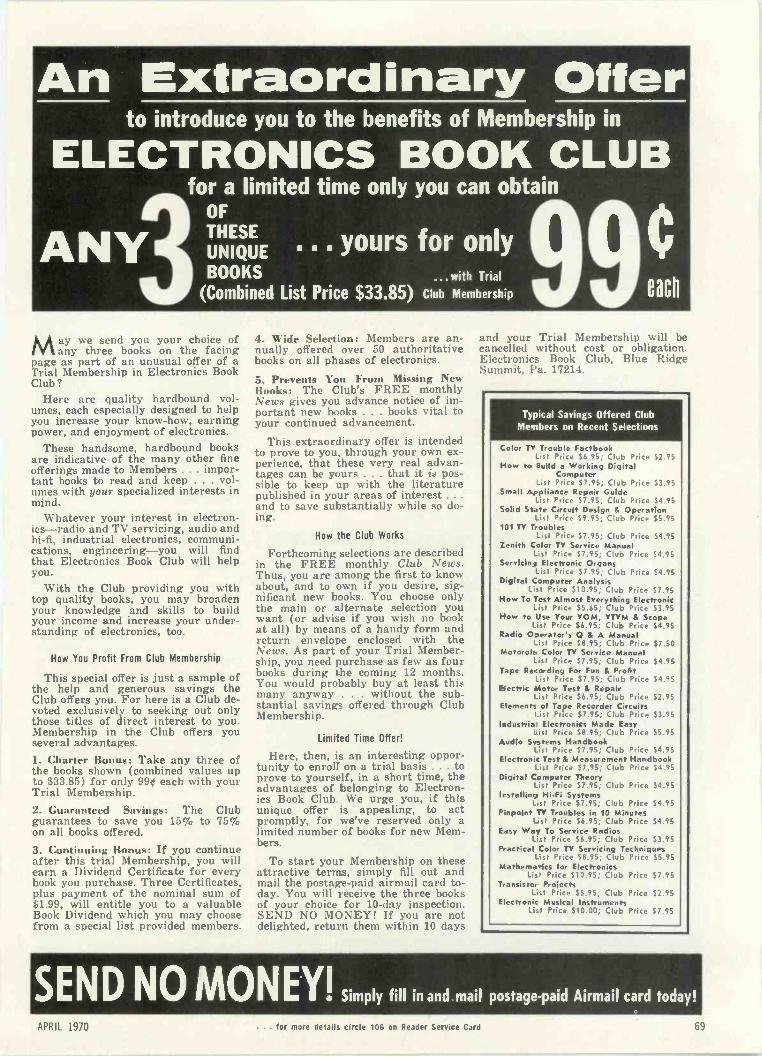
An Extraordinary Offerto introduce you to the benefits of Membership in
ELECTRONICS BOOK CLUB
ANYfor a limited time only you can obtain
OFTHESEUNIQUEBOOKS ...with Trial
(Combined List Price $33.85) Club Membership 9. . . yours for only 0
May we send you your choice ofany three books on the facing
page as part of an unusual offer of aTrial Membership in Electronics BookClub?
Here are quality hardbound vol-umes, each especially designed to helpyou increase your know-how, earningpower, and enjoyment of electronics.
These handsome, hardbound booksare indicative of the many other fineofferings made to Members . . . impor-tant books to read and keep . . . vol-umes with your specialized interests inmind.
Whatever your interest in electron-ics -radio and TV servicing, audio andhi-fi, industrial electronics, communi-cations, engineering -you will findthat Electronics Book Club will helpyou.
With the Club providing you withtop quality books, you may broadenyour knowledge and skills to buildyour income and increase your under-standing of electronics, too.
How You Profit From Club Membership
This special offer is just a sample ofthe help and generous savings theClub offers you. For here is a Club de-voted exclusively to seeking out onlythose titles of direct interest to you.Membership in the Club offers youseveral advantages.1. Charter Bonus: Take any three ofthe books shown (combined values upto $33.85) for only 990 each with yourTrial Membership.2. Guaranteed Savings: The Clubguarantees to save you 15% to 75%on all books offered.3. Continuing Bonus: If you continueafter this trial Membership, you willearn a Dividend Certificate for everybook you purchase. Three Certificates,plus payment of the nominal sum of$1.99, will entitle you to a valuableBook Dividend which you may choosefrom a special list provided members.
4. Wide Selection: Members are an-nually offered over 50 authoritativebooks on all phases of electronics.
5. Prevents You From Missing NewBooks: The Club's FREE monthlyNews gives you advance notice of im-portant new books . . . books vital toyour continued advancement.
This extraordinary offer is intendedto prove to you, through your own ex-perience, that these very real advan-tages can be yours . . . that it is pos-sible to keep up with the literaturepublished in your areas of interest ...and to save substantially while so do-ing.
How the Club Works
Forthcoming selections are describedin the FREE monthly Club News.Thus, you are among the first to knowabout, and to own if you desire, sig-nificant new books. You choose onlythe main or alternate selection youwant (or advise if you wish no bookat all) by means of a handy form andreturn envelope enclosed with theNews. As part of your Trial Member-ship, you need purchase as few as fourbooks during the coming 12 months.You would probably buy at least thismany anyway . . . without the sub-stantial savings offered through ClubMembership.
Limited Time Offer!
Here, then, i4 an interesting oppor-tunity to enroll on a trial basis . . . toprove to yourself, in a short time, theadvantages of belonging to Electron-ics Book Club. We urge you, if thisunique offer is appealing, to actpromptly, for we've reserved only alimited number of books for new Mem-bers.
To start your Membership on theseattractive terms, simply fill out andmail the postage -paid airmail card to-day. You will receive the three booksof your choice for 10 -day inspection.SEND NO MONEY! If you are notdelighted, return them within 10 days
and your Trial Membership will becancelled without cost or obligation.Electronics Book Club, Blue RidgeSummit, Pa. 17214.
Typical Savings Offered ClubMembers on Recent Selections
Color TV Trouble FactbookList Price $6.95; Club Price $2.95
How to Build a Working DigitalComputer
List Price $7.95; Club Price $3.95Small Appliance Repair Guide
List Price $7.95; Club Price $4.95Solid State Circuit Design & Operation
List Price $9.95; Club Price $5.95101 TV Troubles
List Price $7.95; Club Price $4.95Zenith Color TV Service Manual
List Price $7.95; Club Price $4.95Servicing Electronic Organs
List Price $7.95; Club Price $4.95Digital Computer Analysis
List Price $10.95; Club Price $7.95How To Test Almost Everything Electronic
_ist Price $5.65; Club Price $3.95How to Use your YOM. YTVM & Scope
List Price $6.95; Club Price $4.95P.adio Operator's Q & A Manual
_ist Price $8.95; Club Price $7.50Motorola Color TV Service Manual
List Price $7.95; Club Price $4.95Tape Recording For Fun & Profit
_ist Price $7.95; Club Price $4.95Electric motor Test & Repair
List Price $6.95; Club Price $2.95Elements of Tape Recorder Circuits
List Price $7.95; Club Price $3.95Industriai Electronics Made Easy
List Price $8.95; Club Price $5.95Audio Systems Handbook
List Price $7.95; Club Price $4.95Elecwoni: Test & Measurement Handbook
List Price $7.95; Club Price $4.95Digital Computer Theory
List Price $7.95; Club Price $4.95Installing Hi-Fi Systems
Lst Price $7.95; Club Price $4.95Pinpoint TY Troubles in 10 Minutes
Lst Price $6.95; Club Price $4.95Easy Way To Service Radios
List Price $6.95; Club Price $3.95Practical Color TV Servicing Techniques
List Price $8.95; Club Price $5.95Mathemaics for Electronics
List Price $10.95; Club Price $7.95Transistor Projects
List Price $5.95; Club Price $2.95Electronic Musical Instruments
Lis. Price $10.00; Club Price $7.95
SENDNO MONEY! Simply fill in and mail postage -paid Airmail card today!
APR '11 . for more details circle 106 on Reader Service Card 69
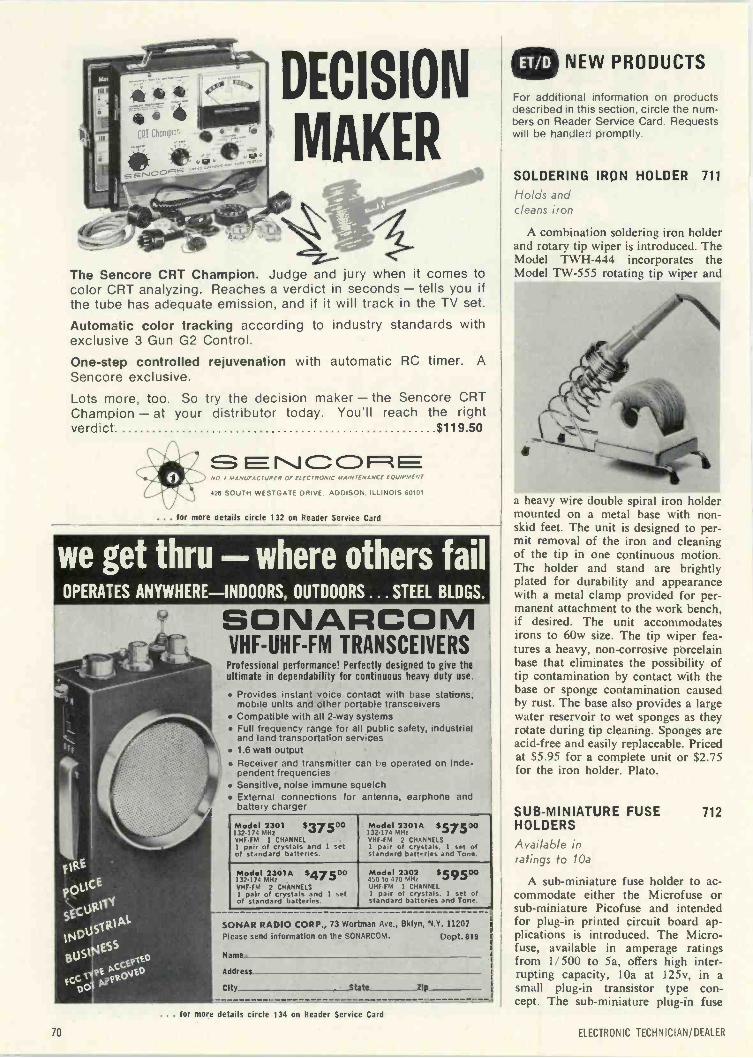
DECISION
MAKER
The Sencore CRT Champion. Judge and jury when it comes tocolor CRT analyzing. Reaches a verdict in seconds - tells you ifthe tube has adequate emission, and if it will track in the TV set.
Automatic color tracking according to industry standards withexclusive 3 Gun G2 Control.
One-step controlled rejuvenation with automatic RC timer. ASencore exclusive.
Lots more, too. So try the decision maker - the Sencore CRTChampion - at your distributor today. You'll reach the rightverdict. $119.50
CD 1=1NO MANUFACTURER OF ELECTRONIC MAINTENANCE EQUIPMENT
426 SOUTH WESTGATE DRIVE. ADDISON. ILLINOIS 60101
... for more details circle 132 on Reader Service Card
we get thru - where others failOPERATES ANYWHERE -INDOORS, OUTDOORS...STEEL BLDGS.
SONARCOMVHF -UHF -FM TRANSCEIVERSProfessional performance! Perfectly designed to give theultimate in dependability for continuous heavy duty use.
Provides instant voice contact with base stations,mobile units and other portable transceivers
Compatible with all 2 -way systems Full frequency range for all public safety, industrial
and land transportation services 1.6 watt output Receiver and transmitter can be operated on inde-
pendent frequencies Sensitive, noise immune squelch External connections for antenna, earphone and
battery charger
Model 2301 $37500132-174 MHzVHF -FM 1 CHANNEL1 pair of crystals and 1 setof standard batteries.
Model 2301A $57500132-174 MHzVHF.FM 2 CHANNELS1 pair of crystals. 1 set ofstandard batteries and Tone.
Model 2301A $47500132.174 MHzVHF -FM 2 CHANNELS1 pair of crystals and 1 setof standard batteries.
Model 2302 $59500.150 to 470 MHzUHF -FM 1 CHANNELI pair of crystals. 1 set ofstandard batteries and Tone.
SONAR RADIO CORP., 73 Wortman Ave., Bklyn, N.Y. 11207Please send information on the SONARCOM. Dept.819
Name-
Address
City State lip
NEW PRODUCTS
For additional information on productsdescribed in this section, circle the num-bers on Reader Service Card. Requestswill be handled promptly.
SOLDERING IRON HOLDER 711
Holds andcleans iron
A combination soldering iron holderand rotary tip wiper is introduced. TheModel TWH-444 incorporates theModel TW-555 rotating tip wiper and
a heavy wire double spiral iron holdermounted on a metal base with non-skid feet. The unit is designed to per-mit removal of the iron and cleaningof the tip in one continuous motion.The holder and stand are brightlyplated for durability and appearancewith a metal clamp provided for per-manent attachment to the work bench,if desired. The unit accommodatesirons to 60w size. The tip wiper fea-tures a heavy, non -corrosive porcelainbase that eliminates the possibility oftip contamination by contact with thebase or sponge contamination causedby rust. The base also provides a largewater reservoir to wet sponges as theyrotate during tip cleaning. Sponges areacid -free and easily replaceable. Pricedat $5.95 for a complete unit or $2.75for the iron holder. Plato.
SUB -MINIATURE FUSE 712HOLDERS
Available inratings to 10a
A sub -miniature fuse holder to ac-commodate either the Microfuse orsub -miniature Picofuse and intendedfor plug-in printed circuit board ap-plications is introduced. The Micro -fuse, available in amperage ratingsfrom 1 /500 to 5a, offers high inter-rupting capacity, 10a at 125v, in asmall plug-in transistor type con-cept. The sub -miniature plug-in fuse
... for more details circle 134 on Reader Service Card
70 ELECTRONIC TECHNICIAN/DEALER
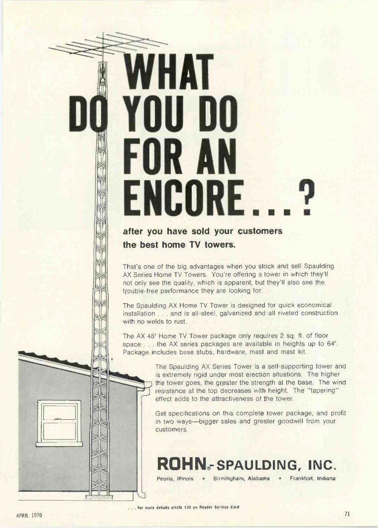
WHATYOU DO
FOR ANENCORE..after you have sold your customersthe best home TV towers.
That's one of the big advantages when you stock and sell SpauldingAX Series Home TV Towers. You're offering a tower in which they'llnot only see the quality, which is apparent, but they'll also see thetrouble -free performance they are looking for.
The Spaulding AX Home TV Tower is designed for quick economicalinstallation . . . and is all -steel, galvanized and all riveted constructionwith no welds to rust.
The AX 48' Home TV Tower package only requires 2 sq. ft. of floorspace . . . the AX series packages are available in heights up to 64'.Package includes base stubs, hardware, mast and mast kit.
La l
The Spaulding AX Series Tower is a self-supporting tower andis extremely rigid under most erection situations. The higherthe tower goes, the greater the strength at the base. The windresistance at the top decreases with height. The "tapering"effect adds to the attractiveness of the tower.
Get specifications on this complete tower package, and profitin two ways-bigger sales and greater goodwill from yourcustomers.
ROHN-SPAULDING, INC.Peoria, Illinois Birmingham, Alabama Frankfort, Indiana
. for more details circle 130 on Reader Service Card
APRIL 1970 71
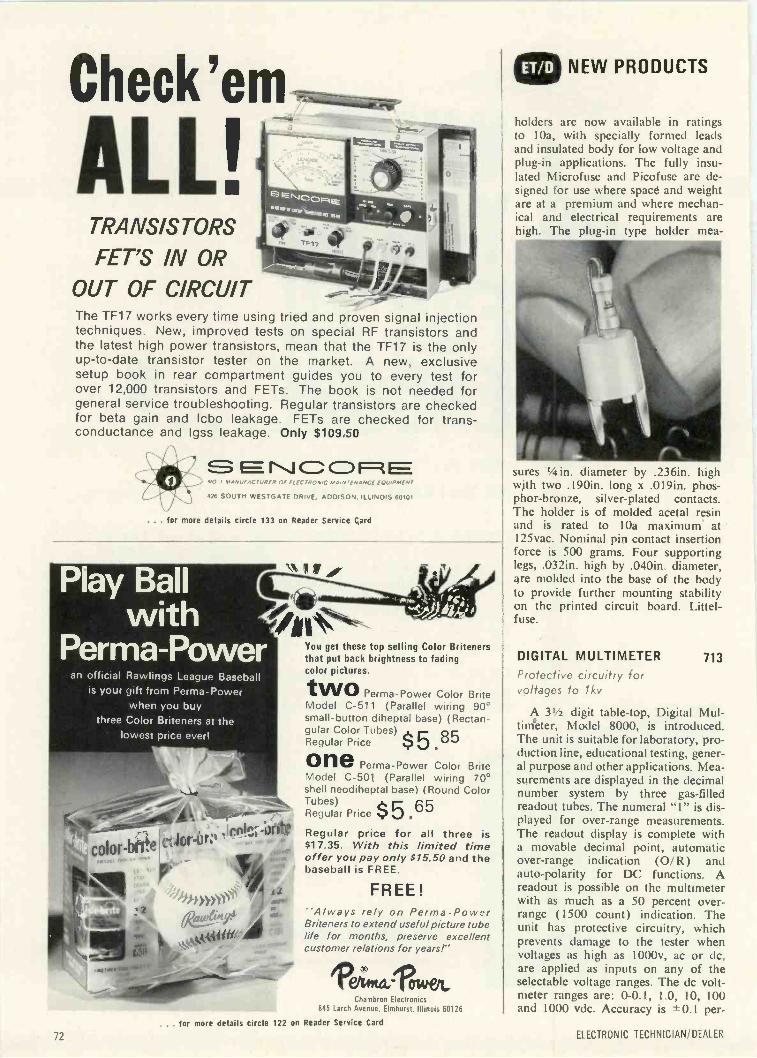
Check'em
ALL!TRANSISTORS
FET'S IN OROUT OF CIRCUITThe TF17 works every time using triedtechniques. New, improved tests on
>'
and proven signal injectionspecial RF transistors and
the latest high power transistors, mean that the TF17 is the onlyup-to-date transistor tester on the market. A new, exclusivesetup book in rear compartment guides you to every test forover 12,000 transistors and FETs. The book is not needed forgeneral service troubleshooting. Regular transistors are checkedfor beta gain and Icbo leakage. FETs are checked for trans -conductance and Igss leakage. Only $109.50
E=Nc cF:tNO I MANUFACTURER VI . MAINTENANCE EQUIPME NI
126 SOUTH WESTGATE DRIVE, ADDISON. ILLINOIS 60101
. . . for more details circle 133 on Reader Service Card
Play Ballwith
Perma-Poweran official Rawlings League Baseball
is your gift from Perma- Powerwhen you buy
three Color Briteners at thelowest price ever)
color-brite ct..lors-or:co.c.,:orite
at, te4.41,
401004. rA ". ..a.
You get these top selling Color Britenersthat put back brightness to fadingcolor pictures.two Perma-Power Color BriteModel C-511 (Parallel wiring 90°small -button diheptal base) (Rectan-gular Color Tubes) c 85Regular Price .8G
one Perma-Power Color BriteModel C-501 (Parallel wiring 70°shell neodiheptal base) (Round ColorTubes)Regular Price $ 5.65Regular price for all three isS17.35. With this limited timeoffer you pay only $15.50 and thebaseball is FREE.
FREE!"Always rely on Perma-PowerBriteners to extend useful picture tubelife for months, preserve excellentcustomer relations for years!"
"Op oraOttl-TOWeit,
Chambron Electronics845 Larch Avenue, Elmhurst, Illinois 60126
NEW PRODUCTS
holders are now available in ratingsto 10a, with specially formed leadsand insulated body for low voltage andplug-in applications. The fully insu-lated Microfuse and Picofuse are de-signed for use where space and weightare at a premium and where mechan-ical and electrical requirements arehigh. The plug-in type holder mea-
sures 'Ain. diameter by .236in. highwith two .190in. long x .019in. phos-phor -bronze, silver-plated contacts.The holder is of molded acetal resinand is rated to 10a maximum at125vac. Nominal pin contact insertionforce is 500 grams. Four supportinglegs, .032in. high by .040in. diameter,are molded into the base of the bodyto provide further mounting stabilityon the printed circuit board. Littel-fuse.
DIGITAL MULTIMETERProtective circuitry forvoltages to 1 kv
A 31/2 digit table -top, Digital Mul-tinieter, Model 8000, is introduced.The unit is suitable for laboratory, pro-duction line, educational testing, gener-al purpose and other applications. Mea-surements are displayed in the decimalnumber system by three gas -filledreadout tubes. The numeral "1" is dis-played for over -range measurements.The readout display is complete witha movable decimal point, automaticover -range indication (O/R) andauto -polarity for DC functions. Areadout is possible on the multimeterwith as much as a 50 percent over-range (1500 count) indication. Theunit has protective circuitry, whichprevents damage to the tester whenvoltages as high as 1000v, ac or dc,are applied as inputs on any of theselectable voltage ranges. The dc volt-meter ranges are: 0-0.1, 1.0, 10, 100and 1000 vdc. Accuracy is ±0.1 per -
713
for more details circle
72
122 on Reader Service Card
ELECTRONIC TECHNICIAN/DEALER
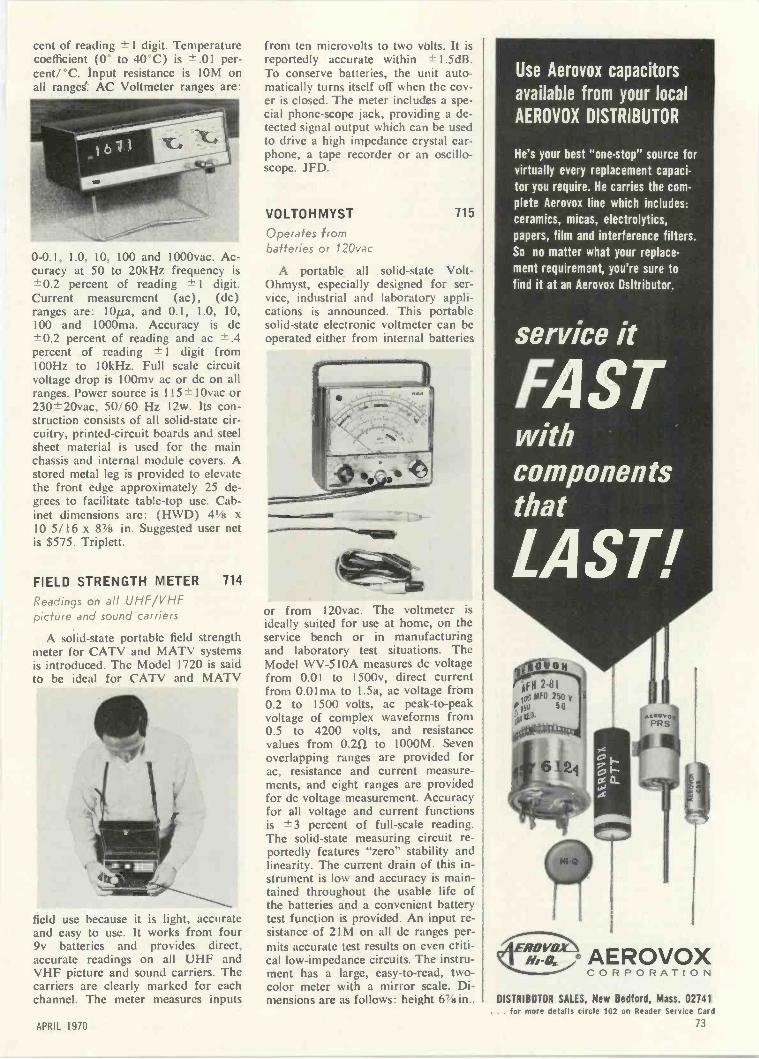
cent of reading ± 1 digit. Temperaturecoefficient (0° to 40°C) is -±.01 per-cent/°C. Input resistance is IOM onall rangei. AC Voltmeter ranges are:
0-0.1, 1.0, 10, 100 and 1000vac. Ac-curacy at 50 to 20kHz frequency is±0.2 percent of reading ± 1 digit.Current measurement (ac), (dc)ranges are: 101a, and 0.1, 1.0, 10,100 and 1000ma. Accuracy is dc±0.2 percent of reading and ac ±.4percent of reading ± 1 digit from100Hz to 10kHz. Full scale circuitvoltage drop is 100mv ac or dc on allranges. Power source is 115±10vac or230±20vac, 50/60 Hz 12w. Its con-struction consists of all solid-state cir-cuitry, printed -circuit boards and steelsheet material is used for the mainchassis and internal module covers. Astored metal leg is provided to elevatethe front edge approximately 25 de-grees to facilitate table -top use. Cab-inet dimensions are: (HWD) 41/8 x10 5/16 x 8% in. Suggested user netis $575. Triplett.
FIELD STRENGTH METER 714
Readings on all UHF/VHFpicture and sound carriers
A solid-state portable field strengthmeter for CATV and MATV systemsis introduced. The Model 1720 is saidto be ideal for CATV and MATV
field use because it is light, accurateand easy to use. It works from four9v batteries and provides direct,accurate readings on all UHF andVHF picture and sound carriers. Thecarriers are clearly marked for eachchannel. The meter measures inputs
from ten microvolts to two volts. It isreportedly accurate within ± 1.5dB.To conserve batteries, the unit auto-matically turns itself off when the cov-er is closed. The meter includes a spe-cial phone -scope jack, providing a de-tected signal output which can be usedto drive a high impedance crystal ear-phone, a tape recorder or an oscillo-scope. JFD.
VOLTOHMYST 715
Operates frombatteries or 120vac
A portable all solid-state Volt-Ohmyst, especially designed for ser-vice, industrial and laboratory appli-cations is announced. This portablesolid-state electronic voltmeter can beoperated either from internal batteries
or from 120vac. The voltmeter isideally suited for use at home, on theservice bench or in manufacturingand laboratory test situations. TheModel WV -510A measures dc voltagefrom 0.01 to 1500v, direct currentfrom 0.01mA to 1.5a, ac voltage from0.2 to 1500 volts, ac peak -to -peakvoltage of complex waveforms from0.5 to 4200 volts, and resistancevalues from 0.211 to 1000M. Sevenoverlapping ranges are provided forac, resistance and current measure-ments, and eight ranges are providedfor dc voltage measurement. Accuracyfor all voltage and current functionsis ±3 percent of full-scale reading.The solid-state measuring circuit re-portedly features "zero" stability andlinearity. The current drain of this in-strument is low and accuracy is main-tained throughout the usable life ofthe batteries and a convenient batterytest function is provided. An input re-sistance of 21M on all dc ranges per-mits accurate test results on even criti-cal low -impedance circuits. The instru-ment has a large, easy -to -read, two-color meter with a mirror scale. Di-mensions are as follows: height 67/8in.,
Use Aerovox capacitors
available from your local
AEROVOX DISTRIBUTOR
He's your best "one -stop" source for
virtually every replacement capaci-tor you require. He carries the com-
plete Aerovox line which includes:ceramics, micas, electrolytics,
papers, film and interference filters.So no matter what your replace-ment requirement, you're sure to
find it at an Aerovox Dsitributor.
service it
FASTwithcomponentsthat
LAST!
YON
Afil 2-810:03 MFG 250 v
i51) 50
0163.,. cr."
oF-
rx
*cmPRS
EROV"0""q..ib-o. AEROVOX
CORPORATION
DISTRIBITOR SALES, New Bedford, Mass. 02741. for more details circle 102 on Reader Service Car -1
73APRIL 1970
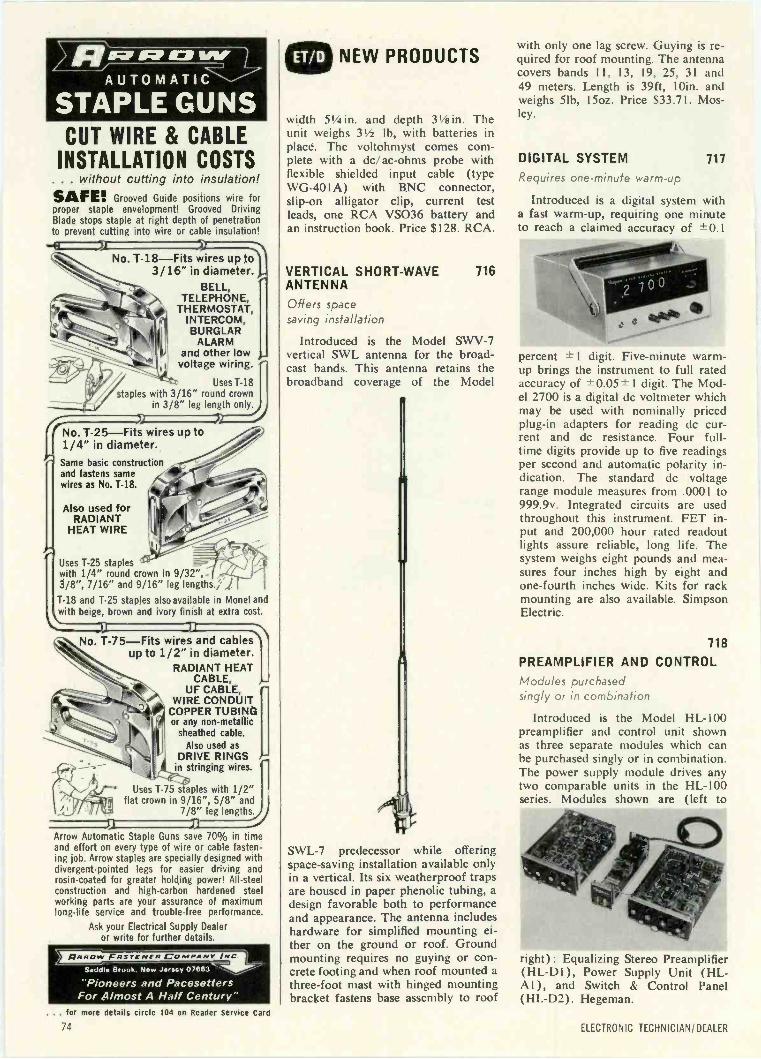
\ q, O;P IC/ WYAUTOMATIC
STAPLE GUNSCUT WIRE & CABLE
INSTALLATION COSTS. . . without cutting into insulation!SAFE! . Grooved Guide positions wire forproper staple envelopment! Grooved DrivingBlade stops staple at right depth of penetrationto prevent cutting into wire or cable insulation!
No. T-18-Fits wires up to3/16" in diameter.
BELL,TELEPHONE,
THERMOSTAT,INTERCOM,BURGLAR
ALARMand other lowvoltage wiring.
Uses T-18staples with 3/16" round crown
in 3/8" leg length only.
No. T-25-Fits wires up to1/4" in diameter.
Same basic constructionand fastens samewires as No. T-18.
Also used forRADIANT
HEAT WIRE
Uses T-25 stapleswith 1/4" round crown in 9/32",3/8", 7/16" and 9/16" leg lengths.; )
T-18 and T-25 staples also available in Monel andwith beige, brown and ivory finish at extra cost.
No. T-75-Fits wires and cablesup to 1/2" in diameter.
RADIANT HEATCABLE,
OF CABLE,WIRE CONDUIT
COPPER TUBINGor any non-metallic
I sheathed cable.Also used as
I) DRIVE RINGSin stringing wires.
Uses T-75 staples with 1/2"flat crown in 9/16", 5/8" and
7/8" leg length/
P't
Arrow Automatic Staple Guns save 70% in timeand effort on every type of wire or cable fasten-ing job. Arrow staples are specially designed withdivergent -pointed legs for easier driving androsin -coated for greater holding power! All -steelconstruction and high -carbon hardened steelworking parts are your assurance of maximumlong -life service and trouble -free performance.
Ask your Electrical Supply Dealeror write for further details.
Saddle Brook. New Jwscy 07663 ........,.,
"Pioneers and PacesettersFor Almost A Half Century"
. for more details circle 104 on Reader Service Card
NEW PRODUCTS
width 51/4 in. and depth 31/2 in. Theunit weighs 31/2 lb, with batteries inplace. The voltohmyst comes com-plete with a dc/ac-ohms probe withflexible shielded input cable (typeWG-40I A) with BNC connector,slip-on alligator clip, current testleads, one RCA VS036 battery andan instruction hook. Price $128. RCA.
VERTICAL SHORT-WAVE 7/6ANTENNA
Offers spacesaving installation
Introduced is the Model SWV-7vertical SWL antenna for the broad-cast bands. This antenna retains thebroadband coverage of the Model
SWL-7 predecessor while offeringspace -saving installation available onlyin a vertical. Its six weatherproof trapsare housed in paper phenolic tubing, adesign favorable both to performanceand appearance. The antenna includeshardware for simplified mounting ei-ther on the ground or roof. Groundmounting requires no guying or con-crete footing and when roof mounted athree-foot mast with hinged mountingbracket fastens base assembly to roof
with only one lag screw. Guying is re-quired for roof mounting. The antennacovers bands II, 13, 19, 25, 31 and49 meters. Length is 39ft, 10in. andweighs 51b, I5oz. Price $33.71. Mos-ley.
DIGITAL SYSTEM 717
Requires one -minute warm-up
Introduced is a digital system witha fast warm-up, requiring one minuteto reach a claimed accuracy of -±0.1
percent ± I digit. Five-minute warm-up brings the instrument to full ratedaccuracy of ±- 0.05 ± 1 digit. The Mod-el 2700 is a digital dc voltmeter whichmay be used with nominally pricedplug-in adapters for reading dc cur-rent and dc resistance. Four full-time digits provide up to five readingsper second and automatic polarity in-dication. The standard dc voltagerange module measures from .0001 to999.9v. Integrated circuits are usedthroughout this instrument. FET in-put and 200,000 hour rated readoutlights assure reliable, long life. Thesystem weighs eight pounds and mea-sures four inches high by eight andone-fourth inches wide. Kits for rackmounting are also available. SimpsonElectric.
718
PREAMPLIFIER AND CONTROLModules purchasedsingly or in combination
Introduced is the Model HL -100preamplifier and control unit shownas three separate modules which canbe purchased singly or in combination.The power supply module drives anytwo comparable units in the HL -100series. Modules shown are (left to
right): Equalizing Stereo Preamplifier( HL -DI ), Power Supply Unit (HL-AI),and Switch & Control Panel(HL -D2). Hegeman.
74 ELECTRONIC TECHNICIAN/DEALER

VHF RECEIVER 719
Operates on30-50 or 148-174MHz bands
Announced is a base or mobile,VHF receiver, which can be operatedin either the 30-50 or 148-174 MHzbands. Called Model TMR-1, the vinyl
clad unit measures 21/4 x 51/2 x 71/2in. The unit includes ac and dc powercords, mobile mounting bracket, de-tachable telescope antenna and builtin 4in. speaker. External speaker ter-minals and standard auto antenna jackare available on the back panel of theunit. Located on the chrome trimmedfront panel are the on/off/volumeand squelch controls plus a powerlamp indicator. Circuitry provides fora single plug-in $4.95 crystal. Fivewatts audio output is complementedreportedly by 1/2iuv sensitivity and50dB selectivity at -±15kHz. Price$99.95. Regency.
DE -SOLDERING TIP 720
Fits standard 3/8in.screw -type soldering gun
Introduced is the model 4918D1Pde -soldering soldering tip which is eas-
ily inserted in a standard 3/a in. screw -type soldering gun of 35w or more.Grooved and channeled for 10, 14 or16 lead dual inline packages, the toolwill reportedly desolder a complete 16pin CIP in one pass and is combinedwith a solder pick up. The end tips areshaped for straightening bent connect -
Clipthecoupons!Present one or more to your participating RCA Test EquipmentDistributor for big discounts on these four instruments duringRCA's big Spring Coupon Carnival. (Only one coupon will beaccepted per instrument.) Do it today. Offer good only betweenFebruary 15th and April 30th, 1970.
'7.50Toward Purchaseof RCA WT -501ATransistor Tester
1-1111111111-11111- =MIMI MIIMI
'10I
00II
1 g
I I
Toward Purchase Iof RCA WT -509APicture Tube Tester
Mr. Distributor, please refer to RCA I mi Mr. Distributor, please refer to RCA I1970 Carnival announcement. Void . 1970 Carnival announcement. Void Ewhere prohibited, taxed, or restricted. I where prohibited, taxed, or restricted.Cash value 1/200. Offer expires II April 30, 1970.
Cash value 1/204. Offer expiresI April 30, 1970.
1111 III OM I 111111 1111 ME Ell MI WI III MN II 1111 WI IIIII MN I OM MD MI MN l IIII
Toward Purchaseof RCA WR-99ACrystal CalibratedMarker Generator'7.50
Toward Purchaseof RCA WV -98CSenior VoltOhmyst 11'20 00,
,,,
,Mr. Distributor, please refer to RCA I E Mr. Distributor, please refer to RCA I1970 Carnival announcement. Void 1970 Carnival announcement. Void
111 where prohibited, taxed, or restricted. a where prohibited, taxed, or restricted.Cash value 1/20g. Offer expires 111 Cash value 1/200. Offer expiresI April 30, 1970. I April 30, 1970.
IIIIII all NM ME MI ME 11111 OM OM I MN 111111111111 MI NM RI
Look to RCA for instruments to test/measure/view/monitor/generate
RCA Electronic Components, Harrison, N. J. 07029
for more details circle 127 on Reader Service Card
APRIL 1970 75

NEW PRODUCTS
or pins. Re -soldering the CIP into po-sition is also possible using the pickupchannel to wick the solder to all points.Tech n i-Tool.
CIRCUIT TESTER 721
Pen -sizedsignal source
The "Mosquito," which finds mul-tiple applications in the field of In-tegrated Circuit testing and provides
an ideal trigger signal for DTL, RTL,and TTL circuits, is introduced. Thissimple but effective device is a cord-
less pen -sized signal source. The unitgenerates and injects pulses coveringthe audio, IF and RF spectrum. Itoperates on a single AAA size 1.5vbattery and weighs one ounce. Theunit can be used for troubleshootingand testing of digital equipment, com-puters, radios and televisions, instru-ments, tape recorders, sound motionpicture projectors, telephone circuits,hearing aids and audio systems, in-cluding amplifiers, reproducers andsound pickup cartridges. Bosco.
MINI -CCTV 722
Weighs less thantwo pounds
Announced is the development of asimple, inexpensive CCTV system withbuilt-in two-way sound. Called Mini -CCTV, the system is small and sim-ple enough to be used by any house-wife. The unit comprises a (2 x 31/2x 51/2 in.) camera, a 5in. monitor,and a 30in. interconnecting cable. In-stallation consists of plugging themonitor into an ac wall socket andconnecting it to the camera by the 30ft cord supplied. Operation involvesaiming the camera and adjustingbrightness and contrast controls onthe monitor for best picture. The cam-era can easily be moved from various
Put it on dirty, greasy, grimy hands . .. it gets them ready -for -lunch clean. Withwater ... without water.Just rub on, wipe off. It dissolves, loosens, removes dirt. Even fingernails and
cuticles look good. No chemical residue to affect electrical com-ponents or rubber goods. And no greasy afterfeel either.
We put in lanolin, left out abrasives and harsh solvents. And it'santiseptic . . . that's really important. It prevents infection fromthose honest -day's -work cuts, scratches, abrasions.
There's a sanitary, just -enough dispenser for the 41/2 -lb. can.Or get the handy 1 -lb. bench -top size. Or 5 -oz. tool kit tube.No petunia smell either.
tv
CRC ChemicalsA Division of C. J. Webb, Inc.Dresher, Pa. 19025
. for more details circle 108 on Reader Service Card
76 ELECTRONIC TECHNICIAN/ DEALER
1 ations, since it weighs less thantwo pounds. Automatic light compen-sation enables the camera to adjust toalmost any light conditions, withoutadjustri, qt. It can produce good pic-tures v, ..1 as little as 20 lux (2 footcandles of scene illumination. In ad-dition to home uses, the MINI -CCTVis also excellent for business purposesand discouraging shoplifting and theft.The 2 -way sound is controlled fromthe monitor, giving the user the optionof listening to sounds from the cameralocation or turning them off. Price$350. GBC.
VIDEOTAPE CONSOLES 723
Any low cost TV camera canbe used with the system
Introduced are mobile video tapeconsole units designed to accommo-date video recorders made by severalmanufacturers. The basic console isformed by two cast fiberglass sectionsenclosing the recorder, audio andvideo monitors and optional equip-ment. All components are mounted toa stainless steel frame, which alsoforms the protective front and rear rubstrips and handles. The lower wheeledbase section provides storage forvideotape and operating supplies. De-signed for operational convenience,the console system is permanentlyconnected to the recorder with its ownI2in. video monitor and speaker. A
hinged plexiglass top cover over thetape deck keeps dust out and noise in.Any low cost TV camera may be usedwith the system. No external cablesare required, as the pedestal cameramount plugs into the top of the con-sole, automatically connecting powerand video to the system. The consolefits Ampex VR-5000, VR-6000 andVR-7000 series videotape recorderswithout modifications to the standardequipment. Additional console unitswill be available in 1970 for Sony, IVCand other recorders. Any lin. Ampexmachine, with the exception of theVR-7800, mounts directly to the con-sole frame once it is removed fromthe factory carrying case. The existing

input-output connection panel fits acutout in the console and the speakermounts in front under the video moni-tor. Installation may be done by non-technical personnel in less than onehour using simple hand tools. A 12in.professional video monitor is includedalready installed, and instructions andhardware are furnished with the "do-it-yourself" kit. Lightweight andsturdy, the console weighs 601b. (lessthe recorder). Mark IV Systems.
TV SHOWROOM ANTENNA 724SYSTEM
Packaged systemserves 12 sets
A packaged master antenna TV(MATV) system for TV showroomsis introduced. The model SL -9004 in-
eludes antenna matching transform-ers, an '82' channel headend amplifier,a two-way splitter, six dual output tap -offs, 12 TV set matching transformers,two line terminators, all necessarycables and connectors. It is reportedlycapable of supplying top quality an-tenna signals (UHF, VHF and FM)to every TV and FM set on the show-room floor. Designed to serve 12 sets,the system can easily and inexpensive-ly be expanded to handle 50 to 100sets. Installation of the showroom sys-tem is easy. It is basically a questionof mounting the individual compo-nents and then plugging them togetherwith cables. A well -illustrated, step-by-step instruction manual facilitatesthe installation. List price $460. JFD.
AMPLITUDE FUNCTION 725GENERATOR
Tone burst andsynchronization capabilities
A function generator, Model 743,reportedly providing low distortionsine, square and triangular wavesover a dial controllable range from1MHz to 2MHz, with an output of upto 20v P -P from a 5052 source imped-ance is introduced. In the VCG or FMmode the generator may be swept from1Hz to 4MHz with amplitude varia-tion claimed of less than ±0.05dB(± 1/2 percent). As features in its
Now it costs lessto own the best
oscilloscopeyou nem,.
40
4r.5
The New RCA WO -505A Solid -State Oscilloscope
'Inexpensive Quality
tOPtional DistributorResale Price
The best you need is the new 5 -inch RCA WO -505A, allsolid-state oscilloscope. It makes yesterday's general-purpose 'scopes look old-fashioned.
At just $298.501 the WO -535A offers an unmatched list offeatures usually found only in more expensive, laboratorytype instruments. For example there's the all solid-statecircuitry ... an illuminated graph screen calibrated directlyin volts, and a deep -lip beze for exceptional clarity. Theregulated power supply minimizes trace bounce and pro-vides excellent stabiliv. Ana the camera mounting studsoffer still more evidence of the functional value built intothe new WO -505A.
But you've got to see this new RCA 'scope in operation-see the sharp, clean trace it arovides-to appreciate it.Some statistics: High -frequency response, usable to 8 MHz. High Sensitivity (.05 V p -p range). DC vertical amplifier; DC/AC input. Return trace blanking ... Trace polarity reversal switch ...
Phase control. High -frequency horizontal sweep; solid lock -in on 5 MHz. Preset TV "V" and ''H" frequencies for instant lock -in.
Built-in square -wave signal for calibrating P -P voltagemeasurements.
Provision for connection to vertical deflection plates ofCRT.
Some statistics! For complete details, contact yourRCA Distributor.
RCA I Electronic Components I Harrison, N. J. 07029. for more details circle 128 on Reader Service Card
APRIL 197077
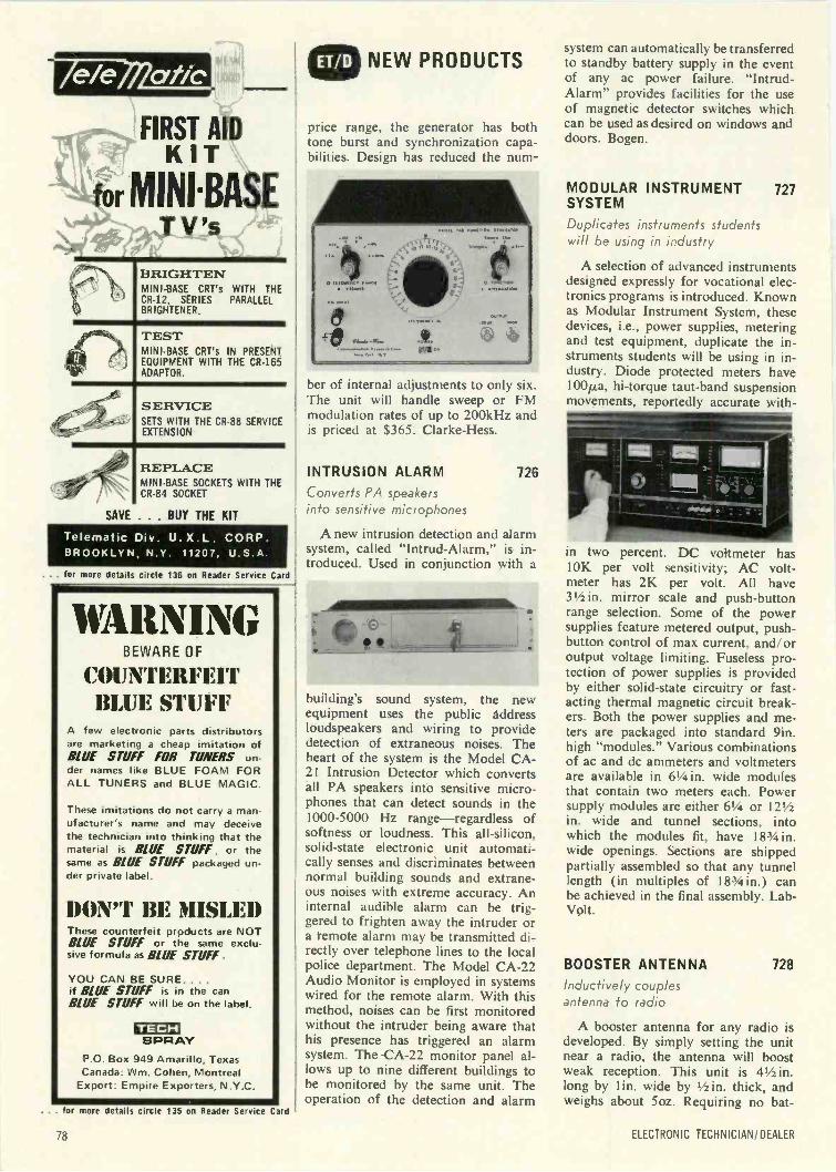
FIRST AIDKIT
for MINISASEr*TV's
BRIGHTENMINI -BASE CRT's WITH THECR-12, SERIES PARALLELBR IGHTENER.
TESTMINI -BASE CRT's IN PRESENTEQUIPMENT WITH THE CR-165ADAPTOR.
SERVICESETS WITH THE CR-88 SERVICEEXTENSION
REPLACEMINI -BASE SOCKETS WITH THECR-84 SOCKET
SAVE . . . BUY THE KIT
Telematic Div. U. X.L CORP.BROOKLYN, N.Y. 11207. U.S.A.
... for more details circle 136 on Reader Service Card
iVARNINGBEWARE OF
COUNTERFEITBLUE STUFF
A few electronic parts distributorsare marketing a cheap imitation ofNUT STUFF FOR TUNERS un-der names like BLUE FOAM FORALL TUNERS and BLUE MAGIC.
These imitations do not carry a man-ufacturer's name and may deceivethe technician into thinking that thematerial is BLUE STUFF , or thesame as BLUE STOff packaged un-der private label.
DON'T BE MISLEDThese counterfeit products are NOTBLUE Sniff or the same exclu-sive formula as BLUE STUFF
YOU CAN BE SURE. . . .
If BLUE sluff is in the canBLUE sniff will be on the label.
TECHSPRAY
P.O. Box 949 Amarillo, TexasCanada: Wm. Cohen, Montreal
Export: Empire Exporters, N.Y.C.
. . . for more details circle 135 on Reader Service Card
NEW PRODUCTS
price range, the generator has bothtone burst and synchronization capa-bilities. Design has reduced the num-
ber of internal adjustments to only six.The unit will handle sweep or FMmodulation rates of up to 200kHz andis priced at $365. Clarke -Hess.
INTRUSION ALARM 726
Converts PA speakersinto sensitive microphones
A new intrusion detection and alarmsystem, called "Intrud-Alarm," is in-troduced. Used in conjunction with a
building's sound system, the newequipment uses the public addressloudspeakers and wiring to providedetection of extraneous noises. Theheart of the system is the Model CA -21 Intrusion Detector which convertsall PA speakers into sensitive micro-phones that can detect sounds in the1000-5000 Hz range-regardless ofsoftness or loudness. This all -silicon,solid-state electronic unit automati-cally senses and discriminates betweennormal building sounds and extrane-ous noises with extreme accuracy. Aninternal audible alarm can be trig-gered to frighten away the intruder ora remote alarm may be transmitted di-rectly over telephone lines to the localpolice department. The Model CA -22Audio Monitor is employed in systemswired for the remote alarm. With thismethod, noises can be first monitoredwithout the intruder being aware thathis presence has triggered an alarmsystem. The CA -22 monitor panel al-lows up to nine different buildings tohe monitored by the same unit. Theoperation of the detection and alarm
system can automatically be transferredto standby battery supply in the eventof any ac power failure. "Intrud-Alarm" provides facilities for the useof magnetic detector switches whichcan be used as desired on windows anddoors. Bogen.
MODULAR INSTRUMENT 727SYSTEM
Duplicates instruments studentswill be using in industry
A selection of advanced instrumentsdesigned expressly for vocational elec-tronics programs is introduced. Knownas Modular Instrument System, thesedevices, i.e., power supplies, meteringand test equipment, duplicate the in-struments students will be using in in-dustry. Diode protected meters have100µa, hi -torque taut -band suspensionmovements, reportedly accurate with-
in two percent. DC voltmeter has10K per volt sensitivity; AC volt-meter has 2K per volt. All have31/2 in. mirror scale and push-buttonrange selection. Some of the powersupplies feature metered output, push-button control of max current, and/oroutput voltage limiting. Fuseless pro-tection of power supplies is providedby either solid-state circuitry or fast -acting thermal magnetic circuit break-ers. Both the power supplies arid me-ters are packaged into standard 9in.high "modules." Various combinationsof ac and dc ammeters and voltmetersare available in 61/4 in. wide modulesthat contain two meters each. Powersupply modules are either 61/4 or 121/2in. wide and tunnel sections, intowhich the modules fit, have 18'/4 in.wide openings. Sections are shippedpartially assembled so that any tunnellength (in multiples of 183/4in.) canbe achieved in the final assembly. Lab -Volt.
BOOSTER ANTENNA 728
Inductively couplesantenna to radio
A booster antenna for any radio isdeveloped. By simply setting the unitnear a radio, the antenna will boostweak reception. This unit is 41/2 in.long by 1 in. wide by 1/2 in. thick, andweighs about 5oz. Requiring no bat -
78 ELECTRONIC TECHNICIAN/DEALER

teries, this miniature antenna systeminductively couples a short antenna to
the radio, increasing the radio's effi-ciency and performance. Price $8.50.Russell Products.
729
PROTO-TYPE BREADBOARD KIT
Equipment designed andbuilt at a minimal cost
A proto-type breadboard kit withslanting front that can be used as an"RF" kit, a conventional R & D lab-oratory kit and also converted to apiece of laboratory test equipment, isintroduced. When the kit is used forcritical "RF" circuitry development,a two-sided copper clad deck withgold-plated, teflon-insulated, feed-thruterminals will accomplish this quitesatisfactorily as components can be
placed on either side of the copperclad deck. When kit is used as a con-ventional R & D laboratory kit, a phe-nolic deck and solder -type, feed-thruterminals will facilitate this require-ment. Solderless connectors are alsoprovided. The slanting front, alumi-num chassis is available with pre -punched holes or plain. An aluminumpre -punched breadboarding deck simi-lar to the copper clad deck is also
available and when used with the per-forated, aluminum cover and the plain,slanting front, aluminum chassis, a per-manent piece of laboratory test equip-ment can be designed and built quick-ly at a minimal cost. The variousbrackets and phenolic spacers fur-nished with this versatile kit allowsthe mounting of any components usedin project development. The kit mea-sures 71/4 in. W x 17in. T x 2in. H.Hook.
DEPENDABLE ALL -
PLASTIC COLOR TUBE
BRIGHTENERS
#CT8-70
Restates "New Set" performance to Color TV Setswhen Color tubes become dull and lose contrastqualitv, after one year. Increases tube brilliance byincreasing the electron emission. All plastic-notpaper! Reusable! Simple installation! Just plug inbetween the color tube and color tube socket. CTB70 for 70' button base pic tubes. =CTB-90 for 90button base pin tubes. Both blister -sealed on attrac-tive, informative Peg -Hang Cards. For Profit Details-Write:
#CTB90
MS ELECTRONICS, INC.50 A.tin Place, Bronx, N.Y. 10462 Tel. (212) 892-6700
. . . for more details circle 129 on Reader Service Card
99.99% reliableEvery now and then, one of our tubes fizzles-
and somehow it's the one you install.Even we don't know how you happento receive that particular tube. But we
do klow that it doesn't happenmore than once in thousands of times.
Raytheon eceiving tubes-includingRaytheon Tubes for Imported Sets-have
to be extra reliable. Because,Raytheon s the leading independent
supplier of receiving tubes toindependent servicemen. We don't
-'4" have competing service trucks orretail out ets. So, we depend on youjust as much as you depend on us.
RAYTHEON
APRIL 1970
. . . for more details circle 175 on Reader Service Card
You're making money in electronics now.
RCA Offers 4 Ways to Make More.
Study at home...set your own pace.
RCA Institutes has an easy approach
to bring you bigger earnings.
r
COLOR TV:During this courseyou'll perform over50 experiments-and receive all partsand instructions tobuild your owncolor TV.
The cost of the Color TV Kit is includedin the tuition in both the beginner's program andthe advanced course in color TV servicing.
Course is based on the latest receiver circuitryand equipment.
SOLID STATE
TECHF1LOGYNew c. arses includethe latest findings andtechniques in this field.Information you musthave if you are to service the multitude of solidstate instruments and devices used in TV, Digital,and Communications equipment.
FCC LICENSE TRAINING:Choose the course for the FCC License you want:third, second or first phone. If you need basictraining first, apply for the complete LicenseTraining Program. Get your License-or yourmoney back.
CATV TRAINING:You'll receive two comprehensive lessons, coveringthe practical phases of CATV systems in either theTelevision Servicing or Communications courses.Licensed by New York State Education Department. Approvedfor Veterans. Accredited Member National Home Study Council.
RCAMAIL THE COUPON NOW FOR COMPLETE INFORMATION.
RCA INSTITUTES, Inc., Dept. 225-004-0
320 West 31st Street, N.Y., N.Y. 10001Please rush me FREE illustrated catalog. I understandthat I am under no obligation.
Name Age(please print)
Address
City
State ZIPL
1
NEWS
OF THE INDUSTRY
NAB AUTHORIZES STUDY OFPROBLEMS CAUSING TOWER ICING
The Engineering Advisory Committee of the NationalAssociation of Broadcasters has ordered a special study ofa problem causing a good deal of concern-ice forming ontransmitter towers.
Appointment of a subcommittee was authorized to in-vestigate the availability of ice -resistant towers or of me-chanical or chemical means to prevent icing. The groupcould also recommend a research project for the develop-ment of such towers or de-icing devices.
Albert H. Chismark, director of engineering, MeredithBroadcasting Co., Syracuse, N.Y., chairman of the Advi-sory Committee, will also serve as chairman of the specialsubcommittee. Others named to the subcommittee wereRobert W. Flanders, director of engineering, the WFBMStations, Indianapolis, Ind.; Royce L. Pointer, director ofbroadcasting engineering, AGC, New York, and BenjaminWolfe, vice-president for engineering, Post -Newsweek Sta-tions, Washington, D.C.
The Advisory Committee also approved plans to developstandards for cassette tape recorders, latest in NAB effortsto assure the interchangeability of broadcast equipment.George W. Bartlett, NAB vice-president for engineering,told the committee that broadcasters arc now using cas-sette recorders quite extensively, particularly in gatheringnews for later presentation on radio.
NAB some years ago adopted standards for disc and taperecordings to assure maximum fidelity in broadcasts andthey now are industry standards throughout the UnitedStates and in most of the world.
The Association later developed a test record to permitstation engineers to evaluate the performance of their audioequipment, including turntables, and since has distributed6000 copies here and abroad.
Distribution of a cartridge test tape has just begun anda second test tape, reel-to-reel, is about ready for distri-bution.
CASTLE TUNERSERVICE MOVES
The Eastern Division of Castle TV Tuner Service an-nounces their move from Long Island City, New York, toRichmond Hill, New York.
Their new, larger premises are set up and equipped withsophisticated analysis facilities to provide thorough over-haul service on all makes of TV tuners for the entire East-ern section of the U.S. A large stock of custom and univer-sal replacement tuners will be available.
The new address is: 130-05 89th Road, Jamaica, N.Y.11418.
The main plant at 5710 N. Western Ave., Chicago, Illi-nois 60645, continues to provide similar service for therest of the U.S.
ZENITH ANNOUNCESPAGING RECEIVER
Zenith Radio Corp. announced development of an ad-vanced solid state personal communications system, usinga new solid state paging receiver, which opens a significantnew field for the company that can lead to further diver-sification in communications.
. . for more details circle 126 on Reader Service CardELECTRONIC TECHNICIAN/DEALER

Joseph S. Wright, Zenith chairman, said, "This achieve-ment by our research and development engineers combinessolid state microcircuits and 'computer language' codingtechniques. The result is a digital paging receiver whichcan increase up to 10 times the number of customers servedby a single narrow band FM channel."
Bell Canada, a Canadian company, has developed andpatented a paging system covering wide -spread areas,known as System Wide Area Paging, "SWAP" and hasentered into a major program to purchase substantial quan-tities of the new units from Zenith.
Zenith will begin production of the microcircuits andassembly of paging receivers this spring, with first deliv-eries slated for July.
The solid state paging receiver weighs only 41/2 ouncesand can be easily slipped into a jacket or shirt pocket, awoman's handbag or clipped to a belt or automobile sunvisor.
Telephone companies, such as Bell Canada, operatingindividual paging systems process messages at a central ex-change to serve businessmen, doctors, lawyers, and otherswho need constant personal communication around -the -clock. The customer has a small paging unit that receivessignals over narrow band FM channels (150 to 160MHz).When called, only the unit being paged emits a tone alertsignal. The customer then can telephone his caller.
Company engineers said the new paging receiver: Expands up to 30,000 the number of individual cus-
tomers served by a single narrow band FM channel. Ex-tension of the coding concept could further increase thenumber up to 100,000.
Permits transmission of signals up to five times persecond as a result of the use of new coding techniques,enabling the paging system to provide continuous, efficientservice even at peak usage hours.
Provides lower unit cost, longer life and greatly re-duced maintenance costs, because of the use of advancedthick film hybrid microcircuits and the latest monolithicintegrated circuits.
Operates economically on readily available transistorradio batteries.
The unit also has a built-in memory, allowing the cus-tomer to interrogate it for calls received in his absence.
The Federal Communications Commission has autho-rized individual paging systems on narrow band FM fre-quencies. Large scale test operations have been conductedby companies in the United States and plans are beingmade for additional installations in many cities throughoutthe country.
CENSUS BUREAU REPORTS ONELECTRON TUBES
Manufacturers' shipments of receiving type electrontubes in 1967 were valued at $256.1 million. This is a de-crease of $31.8 million from 1963, the year of the last pre-vious Census of Manufactures, according to a preliminaryreport just issued by the U.S. Department of Commerce'sBureau of the Census.
Total number of employees in the industry was 21.2thousand in 1967, a drop of 4.6 thousand from 1963. Pay-rolls for 1967 totaled $119.5 million as against $136.8 mil-lion in 1963.
Value -added -by -manufacture was $227.7 million in 1967-in 1963 the total was $250.7 million. Value-added ap-proximates the value of products shipped less the cost ofmaterials used in the manufacture of the products.
The report, "Electron Tubes, Receiving Type," MC67(P) -36D-5, is for sale by the U.S. Bureau of the Census,Washington, D.C. 20233 and U.S. Department of Com-merce field offices (located in principal cities throughoutthe United States). The price is 10 cents per copy.
-4 0 Z / N TA-A NEW TOOL FOR CLEANING
CONTROLS OF TV AND AUTO RADIOSTHRU FRONT PANELS
MODEL NO. WJLPACKAGED WITH 3 OZ. AEROSOL
LUBRITE. DEALER COST $2.67MANUFACTUREDWORKMANSARASO TA L OR$O PRODUCT'S RIC
BY
. for more details circle 142 on Reader Service Card
nq COAXLINE SPLITTER
For UHF/VHFColor/B&W TV
The Mosley M-22two set, and M-24 four set75 ohm coax splitters for color TV/FMStereo distribution systems. High inter -
set isolation, low insertion loss.Models may to combined to provide
any number of lines for largeramplified systems.
Solderless. Easyinstallation.
edr
Write Dept. 15SA for FREE detailed brochure.
egclizonzt4Sn44610 N. Lindbergh Blvd.,Bridgeton Missouri 63042
APRIL 1970... for more details circle 120 on Reader Service Card 81

SERVICE MASTER
HANDIEST
HANDFUL
of service tools
23 essential tools at your fingertips in this light-weight (only 234 lbs.), compact, easy -to -carry,roll -up kit. Contains long nose plier, diagonalplier, adjustable wrench, regular and stubbyplastic handles with these interchangeableblades: 9 regular and 3 stubby nutdriver, 2slotted and 1 Phillips screwdriver, 2 reamer, 1extension. Eyelets in plastic -coated canvas casepermit wall hanging. New elastic loop securesroll, eliminates need for tying.
many optional accessories:Junior and Tee handles...Additional nutdriver,Phillips & slotted screwdriver, and extensionblade sizes ... Allen hex type, Bristol multiplespline, frearson, Scrulox, and clutch head blades...Awl/Scriber...Chuck adaptors to use bladesin spiral ratchet drivers.
WRITE FOR CATALOG 166
XCELITE, INC. 14 Bank St., Orchard Park, N.Y. 14127In Canada contact Charles W. Polnton, Ltd.
... for more details circle 143 on Reader Service Card
CATALOGS ft
BULLETINS
400
TV Parts Cross -Reference Guide
Offered is the color and mono-chrome TV Parts Replacement Guide.The Part -to -Part Cross ReferenceGuide contains replacement parts for200 television manufacturers. Thisyear a new section has been addecicovering the line of flybacks, deflec-tion yokes, vertical outputs, powerand output transformers, filter chokes,plus several pages of electrical sche-matics. Stancor.
RF Voltmeter 401
A specification sheet lists the Model500 HFE RF Voltmeter, a high -ac-curacy self-contained instrument forhandling the frequency range 20kHzto 500MHz over a potential rangefrom 200mv to 15 volts. The litera-ture illustrates the instrument withemphasis on the low -capacitance bi-furcated probe, which increases ac-curacy and simplifies measurements.High Frequency Engineering.
Ceramic Strip 402
A 4 -page catalog containing threefamilies of ceramic strips are ex-plained and illustrated, thread mount-ing standard types, plug-in miniaturesand universal types with snap mount-ing. A specially created design boardkit is available for prototype and in-structional use. The terminal stripsdescribed are ceramic -base units withfired silver, copper plated and tinnedterminals to facilitate high temperaturesoldering of components and leads.Alcostrip.
Electronic Importers Directory 403
A 1970 Electronic Importers Di-rectory is available. Listing over 150U.S. based importers of electronicmerchandise the directory combines atotal of over 5,000 brands and modelsto choose from. A partial list of itemscovered include radios, stereos, cas-sette recorders, amplifiers, speakersystems, musical instruments, cameras,TVs, UHF and VHF equipment pluselectronic components. It gives com-plete information on the importer,including name, address, phone no.,items carried and brand names used.Pictorial display on some items. Price$9.95. Commodore Publications.
Test Instruments 404
A 12 -page catalog describing thecompany's complete line of electronicequipment is available. The catalog,
Form No. 517, features five complete-ly new instruments including the sixthgeneration of the company's MightyMite tube tester, two-color generators,a field effect transistor tester and aseven -in -one bias supply. Other in-struments included in the catalog arefield effect meters, sweep and markergenerator, sweep circuit analyzer,combination oscilloscope/vectorscope,combination transistor/FET testers.CRT tester and special purpose in-struments, all complete with perform-ance data and prices. Sencore.
TV Cheater Cords 405
A data sheet on the complete lineof television cheater cords is pub-lished. The UL -approved cords are all10a, 125v hanked power supply cordswith molded caps and connectors,available in six or nine foot lengths,in brown or white. Caps are standard,polarized with pins. Connectors arestandard with ears, snap -in or standardC clip; polarized with ears, C clip,snap -in, or polarized misalignment.Columbia Electronic Cables.
Wire Stripping 406
An 8 -page, two-color brochure, No.6 describing hand and bench mountedwire strippers is available. The bro-chure offers helpful suggestions onhow to select the correct wire strip-per for your specific requirements.Various models of mechanical handstrippers, bench mounted strippers andthermal strippers are described in de-tail with complete specifications, op-erational drawings and ordering infor-mation. Ideal Industries.
Linear IC Tester 407
An 8 -page brochure on a linear ICtester describes LIC testing and eval-uation of circuit performance in spe-cial purpose applications. The testeris a multi -purpose unit designed tosimulate various conditions underwhich LIC's may operate; it can alsobe used in failure analysis of IC de-vices. The unit affords the evaluationof IC's such as op amps, comparators,differential amplifiers and it allowsthe study of transistor characteristics.I. C. Metrics, Inc.
Transistors 408
A 12 -page brochure describes theSilect line of low-cost transistors. De-tails are given on plastic -encapsulatedsilicon bipolar, unijunction, and field-effect transistors. Featured in the pub-lication is a report on more than 33million hours of testing transistors,establishing the fact that the devicesmeet high reliability specifications. Anapplication's guide listing device rec-ommendations and electrical parame-
82 ELECTRONIC TECHNICIAN/DEALER

ters is included. The brochure dis-cusses and illustrates the exclusivetransistor package construction. A de-vice cross-reference in the bookletlists transistor type designations, di-rect replacements, preferred types andnearest equivalents for easy selectionby designers. Texas Instruments.
Panel Instruments 409
A 32 -page catalog describing over1,500 stock ranges, sizes and types ofpanel instruments is published. In-cluded is a quick -reference index onthe cover for fast locating of rangesand types in the desired case style.Being introduced are the new CenturySeries panel instruments, which com-bine the advantages of a modernclean-cut design with phenolic andglass construction. Available for im-mediate delivery in four sizes, theycan be used to directly replace olderglass and phenolic designs. Also in-troduced are the model 2800 digitalpanel instruments. Advanced inte-grated circuit design has non -blinkingreadouts, changing only when themeasured value changes. Accuracy ofthese readings are reportedly ±0.1percent with resolution of 1 part in1000. Simpson Electric.
Subminiature Indicator Lights 410
Bulletin No. 1470, describing theline of subminiature indicator lightsis offered. These indicator lights havebeen engineered and are manufacturedwith the idea of achieving the ultimatein simplicity, standardization, reliabil-ity and cost reduction. The indicatorsare front relampable and house anystandard T-1 lamp, wire lead type, tomeet customer requirements of spe-cific voltage, current and life expec-tancy. Caps are offered in a variety oftransparent and translucent colors forcoding purposes. Bloc-Lite.
Communications Range and 411
Cost Calculator
Offered is an easy -to -use slide rulewheel calculator which answers themost commonly asked questions abouttwo-way radio communications sys-tems: How far can a given system beexpected to communicate? What af-fect will using gain antennas, increas-ing tower height, transmitter power, orreceiver sensitivity have upon perform-ance and system cost? The calculatorenables a person to estimate systemcosts and ranges in a matter of min-utes. The speed of calculation allowsone to quickly plan several systems-varying transmitter power, type of an-tenna, tower height, etc. It also givesthe most economical means of achiev-ing the desired system performance.Other factors taken into considerationby the calculator are receiver sensitiv-
ity, frequency of operation, vehiclenoise level, type of coaxial cable andenvironmental factors such as hillyterrain, flat terrain, suburban, urbanand industrial locations. Antenna Spe-cialists.
Power Supplies 412
A condensed, 28 -page catalog de-scribing power supplies is offered. Itfeatures the LVC II/PVC line of lab-oratory and bench supplies which offera new concept of regulation throughthe use of accessible plug-in regulatorcards in either the voltage or currentoutput modes. Voltage ranges for theLVC II/PVC line are 0-10v, 20v and50v, while power loads range from25w, 50w, and 100w, respectively. Al-so described in the illustrated catalogare system rack and modular supplies;over 200 voltage and current regula-tion models; high voltage suppliesfrom 2.5 to 250kv frequency convert-ors, 60Hz to 400Hz and a completedescription of custom capabilities.NJE Corporation.
Tape Deck 413
Released is a product bulletin onthe Model 407 solid-state stereo tapedeck. The bulletin lists features andtechnical specifications. Also describedare the professional facilities and con-venience features. Astrocom/Marlux.
Digital Panel Meters and 414DC Amplifiers
A 4 -page shortform catalog cover-ing Panel Meters, DC Data Amplifiers,Galvo Drivers, Dual DC Power Sup-plies, DC Differential Amplifiers, Pho-tomultiplier Amplifiers and Voltage -to -Frequency Converters is offered.Covered in the shortform are over 30models and 12 options found in thedigital panel meters for DC Voltage,AC Voltage, Ratio, DC Current andAC Current in two, three and fourdigit models. Performance featuresand mounting options are also cov-ered. Newport Lab's.
Time Dial/Radio 415Frequency Charts
A pocket-size world time dial com-bined with radio frequency charts letsyou convert time differences betweenlocal standard times and other citiesthroughout the world as well as to(GMT) Greenwich Mean Time, is
offered. The compact, two-color selec-tor measures four by five inches insize. It is a needed reference for thenovice or advanced short -waver thatcompliments any short-wave radioshack. It is in use with a turn of thebig, easy -to -read dial. Frequencycharts that are clearly given on thebackside of the time dial selector, in -
REBUILDYOUR OWN
PICTURE TUBES?
With Lakeside Industries precision equip-ment, you can rebuild any picture tube!
EASY TO OPERATE!
Requires only 4 x 8 ft. of space.Your cost to rebuild black and white-$1.50.You cost to rebuild Color-$5.80.For complete details, mail coupon.
LAKESIDE INDUSTRIES5234 N. Clark St.Chicago, III. 60640Phone: 312-271-3399
n Free demonstration appointmentE Send me more information
Name
AddressCity State
. for more details circle 117 on Reader Service Card
IF YOU ARE A TVREPAIR MAN YOU NEED
TV TECH AIDTV TECH AID is the best trouble shootingguide available today. It takes all theguesswork out of TV repair and is de-signed to help you solve your problemsquickly and economically.Each month you receive updated informa-tion on up to 40 different trouble -shootingcases. This important information is sup-plied to us by technicians, field reps andall the leading TV manufacturers. You willfind every symptom pictured with a clearlymarked schematic of the particular faultystage. The faulty components and correc-tions will also be listed to aid in repair.You go right to the source of the troublewithout guesswork. In addition you getvaluable information on current models aswell as older models along with circuitchanges and modifications as they occur.TV TECH AID is the best investment youran make in your own business. The costto you is only $7.95 for a full year'ssubscription.
Send for it now ... You'll be glad you did!
TV TECH AIDP.O. BOX 603ICINGS PARK, L. I.NEW YORK 11754ENCLOSED IS A CHECK OR M.O. FOR$7.95. PLEASE SEND 12 ISSUES OF TVTECH AIDTO:
NAME
ADDRESS .
CITY
STATE ZIP
.. for more details circle 138 on Reader Service Card
APRIL 1970 83

CATALOGS Et
BULLETINS
elude: International Short -Wave broad-cast bands and frequencies, Radio andTV broadcasting bands, Communica-tions and Navigation frequencies (Air-craft, Marine, Citizens Radio, FMtwo-way, Police, Fire, Business andothers) Amateur bands, StandardTime and Frequency Signals. Halli-crafter.
VECTORSCOPE."continued front page 49
It is also possible to align the ad-justable demodulators in a set byusing a vector display. To do this, itis necessary to have a set of align-ment instructions for the particularreceiver so you can locate the prop-er adjustments. Follow the instruc-tions in the alignment procedure.However, in place of counting thebars, simply adjust for the properangle between the R -Y and B -Y pet-als on the vector display.
A NOTE OF CAUTION: Do not at-tempt any alignment of the chromabandpass amplifiers. These circuitsmust be aligned with a sweep gen-erator and cannot be aligned by avector display.
VECTOR DISPLAY SYMPTOMS
(1) Petals of vector display ro-tate. TROUBLE: Loss of color sync,color oscillator free running. (2)Vector display pattern elliptical.TROUBLE: The color amplifiers areweak or unbalanced. (3) Petals ofvector display are flattened orcrushed. TROUBLE: The color am-plifiers are overloaded. (4) Anglesbetween R -Y and B -Y petals are not90 or 105 degrees, depending onmanufacturers' specifications. TROU-BLE: Color demodulators are out ofalignment. (5) The R -Y petal can-not be made to reach the vertical po-sition. TROUBLE: There is a loss ofrange in the hue control. IS
CURVE TRACER ...continued from page 47
presentation shown in figure 1. Anexample is the curve of the 1st au-dio amplifier shown in figure 3. Of-
84
ten the curves will become loops orthey will droop or take on some oth-er odd shape. But as long as thecurves are there, the circuit undertest has a working transistor in it.
As in the standard family ofcurves, the lines represent definiteparameters. A deflection in the hori-zontal direction shows that the col-lector -to -emitter of the transistorwill support a voltage drop. A de-flection in the vertical directionshows the collector is capable ofcontrolling current as the base cur-rent is varied in steps.
TECHNIQUE IMPROVES WITHEXPERIENCE
With increased experience in theuse of this technique, it is felt thatan operator will learn to identify thequality of the transistors as well astheir condition. In fact, as this tech-nique wins acceptance, it is possiblethat future schematics might showthe 'dynamic curves' of each tran-sistor used.
Because the transistor under testwith this method is never in dangerof destructive voltage or currents, itappears this may also be one of thesafest 'in -circuit' techniques avail-able. It seems to work with any cir-cuit, and because it affords a fast,safe means of troubleshooting, itsuse can be reasonably expected tohave universal application.
The primary function of the tran-sistor curve tracer up to now hasbeen for identification and testing ofout -of -circuit transistors. Since ev-ery TV manufacturer uses specifiedtransistors with their own numberingsystem, the curve tracer allows atechnician to make a satisfactory se-lection from his stock of transistorsthus saving time and eliminating theneed for an over -large inventory.
In a future article, we will take alonger look at the use of the curvetracer to identify transistor substi-tutes plus out -of -circuit checkingand how to use the tracer to chooseemergency substitutes for diodesand zeners.
Get More FactsNEW PRODUCTS700 H Lo Band FM. VHF Monitor701 VHF Marine Radio Telephone702 Clock703 Soldering Iron704 Coaxial Relay705 Two -Station Intercom ...706 Cassette Classroom System
26262626626262
707 Telephone Amplifier 62708 Slide Synchronized Cassette Recorder.. 64709 Ham Band Receiver 64710 Battery Displays 64711 Soldering Iron Holder 70712 Sub -Miniature Fuse Holders 70713 Digital Multimeter 72714 Field Strength Meter 73715 Voltohmyst ........ . 73716 Vertical Short -Wave Antenna 74717 Digital System 74718 Preamplifier and Control 74719 VHF Receiver 75720 De -Soldering Tip 75721 Circuit Tester 76722 Mini -CCTV 76723 Videotape Consoles 76724 TV Showroom Antenna System 77725 Amplitude Function Generator 77726 Intrusion Alarm 78727 Modular Instrument System . 78728 Booster Antenna 78729 Proto-Type Breadboard Kit . 79
TEST INSTRUMENTS900 Telequipment D54 Oscilloscope 51
CATALOGS AND BULLETINS400 TV Parts Cross -Reference Guide 82401 RF Voltmeter 82402 Ceramic Strip 82403 Electronic Importers Directory 82404 Test Instruments 82405 TV Cheater Cords 82406 Wire Stripping 82407 Linear IC Tester 82408 Transistors 82409 Panel Instruments 83410 Subminiature Indicator Lights 83411 Communications Range and Cost Calculator 83412 Power Supplies 83413 Tape Deck 83414 Digital Panel Meters and DC Amplifiers 83415 Time Dial 'Radio Frequency Charts 83
ADVERTISER'S INDEX101 Admiral Corp. 58102 Aerovox Corp. 73103 Antenna Corp. of America 28104 Arrow Fastener Co., Inc. 74105 B & K Div. Dynascan Corp. 23106 Book Club-Tab Books 66.69107 Borden Chemical Co. 29108 CRC Chemicals 76109 Channel Master Corp. 31110 Chemtronics, Inc. 3rd Cover111 Chrysler Corp., Dodge Div. 55112 EICO Electronic Instruments
Co., Inc. 2nd Cover113 Ford Motor Company 36114 GC Electronics Co. 22115 Grantham School of Engineering 84116 The Heath Company 57117 Lakeside Industries 83118 Leader Instruments Corp. 30119 Lectrotech, Inc. 34120 Mosley Electronics, Inc. 81121 Pennwood Numechron Co. 30122 Perma-Power Company 72123 Philips Business Systems, Inc. 35124 Quietrole Company 30125 Raytheon Company 79
RCA Electronic ComponentsBattery Div. 59RCA Electronic ComponentsEntertainment Tubes 4th Cover
126 RCA Institutes, Inc. 80RCA Parts & Accessories 33RCA Semiconductor Distributor Products 20
127 RCA Test Equipment 75128 RCA Test Equipment 77129 RMS Electronics, Inc. 79130 Rohn Manufacturing Co. 71131 Sencore. Inc. 64132 Sencore, Inc. 70133 Sencore, Inc...,..72
.
134 Sonar Radio Corp.Sylvania Electric Products . 24-2750Sylvania Electric Products 65
135 Tech Spray ...78136 Telematic Division UXL Corp. . ..78137 Tuner Service Corp. 19138 TV Tech Aid 83139 Weller Electric Corporation 60140 Jud Williams 61141 Winegard Company 63142 Workman Electronic Products, Inc. 81143 Xcelite, Inc. 82
Zenith 27
Technicians, Earn Your Associate
DEGREEmostly by correspondence
Accredited by the Accdt. Comm. of National HomeStudy Council. G.I. Bill Approved. Free catalog.Write: Dept. T
Grantham School of Engineering1505 N. Western. Hollywood. Calif. 90027
. . . for more details circle 115 on Reader Service Card
ELECTRONIC TECHNICIAN/DEALER
FOR MORE INFORMATION fill out and mail today!
GET
MORE
.FACTS
NO POSTAGE
NECESSARY
Circle
the
Reader
Service
numbers
of those
items of
interest
to you.
OK
Please send more information on items circled.
ADVERTISED PRODUCTS (Please type or print) 4/10101 102 103 104 105 106 107 108 109
110 111 112 113 114 115 113 117 118 Name
119 120 121 122 123 124 125 126 127
128 129 130 131 132 133 134 135 136 Position
137 138 139 140 141 142 143 144 145
146 147 148 149 150 151 152 153 154 Conpany
TEST INSTRUMENTS Street900 901 902 903 904 905 906 907 908
NEW PRODUCTS City
700 701 702 703 704 705 706 707 708
709 710 711 712 713 714 715 716 717 State Zip Code
718 719 720 721 722 723 724 725 726
727 728 729 730 731 732 733 734 735 Please describe your type of business.
CATALOGS & BULLETINS
400 401 402 403 404 405 406 407 408
409 410 411 412 413 414 415 416 417
Note: Inquiries serviced until June 22, 1970.
FOR MORE INFORMATION fill out and mail today!Please send more information on items circled.
ADVERTISED PRODUCTS (Please type or pri It) 4/70101 102 103 104 105 103 107 108 109
110 111 112 113 114 115 116 117 118 Name
119 120 121 122 123 124 125 126 127
128 129 130 131 132 123 134 135 136 Position
137 138 139 140 141 142 143 144 145
146 147 148 149 150 151 152 153 154 Company
TEST INSTRUMENTS Street900 901 902 903 904 905 906 907 908
NEW PRODUCTS City
700 701 702 703 704 705 106 707 108
709 710 711 712 713 714 715 716 717 State Zip Code
718 719 720 721 722 123 724 725 726
727 728 729 730 731 732 733 734 735 Please describe your type of business.
CATALOGS & BULLETINS
400 401 402 403 404 405 406 407 408
409 410 411 412 413 414 415 416 417
Note: Inquiries serviced until June 22, 1970.
Enter my personal subscription to ELECTRONIC TECHNICIAN, DEALERfor the terms checked below:
NAME
$10 FOR 3 FULL YEARS
$8 FOR 2 YEARS
o $5 FOR 1 YEAR
o PAYMENT ENCLOSED
o BILL ME LATER
1=3 If you are renewing
your subscriptioncheck here and
attach your add-ess
label.
TITLE
FIRM
STREET
CITY STATE
PLEASE CHECK BELOW:
1. In the T. Radio aid other consurer products fields, is your fernPRIMARILY a: (check most descriptive item)
Retailer with sery cedepartmentService repair firm Owner, manager, buyer,with some retail other executiveIndustrial electronics Service managerservice firm Service repairman orManufacturer other employee
E Other (please describe)
ZIP
2. Title: (please check one)

BUSINESS REPLY MAILNO POSTAGE STAMP NECESSARY IF MAILED IN THE UNITED STATES
POSTAGE WILL BE PAID BY
Reader Service Department
ELECTRONICTECHNICIAN / DEALERHARBRACE BUILDING, DULUTH, MINNESOTA 55802
FIRST CLASSPERMIT NO. 665DULUTH, MINNESOTA
BUSINESS REPLY MAILNO POSTAGE STAMP NECESSARY IF MAILED IN THE UNITED STATES
POSTAGE WILL BE PAID BY
Reader Service Department
ELECTRONICTECHNICIAN / DEALERHARBRACE BUILDING, DULUTH, MINNESOTA 55802
BUSINESS REPLY MAILNO POSTAGE STAMP NECESSARY IF MAILED IN THE UNITED STATES
POSTAGE WILL BE PAID BY
Circulation Department
ELECTRONICTECHNICIAN / DEALERHARBRACE BUILDING, DULUTH, MINNESOTA 55802
FIRST CLASSPERMIT NO. 665
DULUTH, MINNESOTA
FIRST CLASSPERMIT NO. 665DULUTH, MINNESOTA
GET
MORE
FACTSNO POSTAGE
NECESSARY
GET
MORE
FACTSNO POSTAGE
NECESSARY
FOR
ONLY
PENNIES
PER
MONTH-YOUR
OWN
PERSONAL
COPIES

HERE'S PROOF
TUN -O -FOAMKEEPS TUNERS
WORKING BETTER
...LONGER!
THIS TUNERWAS USED AS IT CAME FROM
THE MANUFACTURERAfter 36,000 revolutions, the silver has been worn away.
The tuner does not function on any channel.
THIS TUNER WAS SPRAYEDWITH TUN -O -FOAM
After 36,000 revolutions there is no sign of wear.The tuner brings in all channels, sharp and r /Plr
THEPROFESSIONAL'S
TV TUNER CLEANER
-4fzFOAMING AC1u7
F OAP.
Foams into the tighestplaces. Won't cake up,dry out or detune. Keepsclean.lg and lubricatingcontacts each time chan-nel is changed. Guaran-teed to be the best tunerlubricant cleaner you'veever used, or money re-funded. Full Six monthno -callback guarantee.
1260 RALPH AVENUECHEMTRONICS---- BROOKLYN, N.Y. 11236
For export: ROBURN AGENCIES INC.. NEW YORK. N.Y. 10014 In Canada: MAGNASONIC CANADA LTD., MONTREAL 9, CANADA
. for more details circle 110 on Reader Service Card

When you don't have time totake it back to the bench...
take this book to the home.
Volume 3
Field -Service Guidefor RCA Color -TV Receivers1969-1970CTC -22 through CTC - 40
IIRT.102
Por
Tells all, shows all, for in -the -homecircuit adjustments on latest RCA color TV's
Here's Volume 3 of the renowned FieldService Guide-the most complete TV serv-ice reference of its kind! Add this new edi-tion to Volumes 1 and 2 and you're readyfor every RCA color TV dating back to 1955.Seven sections in easy -to -understand form,schematics, plus waveforms and illustratedadjustment procedures:
1General Field Service Adjustments.Step-by-step procedures and illustra-
' tions for adjusting purity, black -and -white setup, static and dynamic con-vergence, and AFPC.
r) RCA Receiving Tubes for Color TV.Lists all the type numbers used in
. RCA color receivers.
3Chassis Section. Specific proceduresfor adjustment of each chassis series.
' top -and -rear views, tube removal di-rections, etc.
4 Parts List. Includes major components. and their replacement part numbers.
ONLY $1.90*'Optional Price
See your RCA Tube Distributor for detailson how you can get this valuable Guide.
5 Tuner Section. Schematics, transistor RCA Electronic Components Harrison, N.J.. and electrical control parts lists.
6 Remote Tuner Section. Schematics oftransmitters and receivers in tuners
' used in Chassis Series CTC-22 toCTC-40.
7Index. Cross-references for all receiv-ers by model numbers, set names and
. chassis numbers. RCA