electronic portal imaging devices: a review and historical
TRANSCRIPT

INSTITUTE OF PHYSICS PUBLISHING PHYSICS IN MEDICINE AND BIOLOGY
Phys. Med. Biol. 47 (2002) R31–R65 PII: S0031-9155(02)07073-2
TOPICAL REVIEW
Electronic portal imaging devices: a review andhistorical perspective of contemporarytechnologies and research
Larry E Antonuk
Department of Radiation Oncology, University of Michigan, UH-B2C432, 1500 East MedicalCenter Drive, Ann Arbor, MI 48109-0010, USA
E-mail: [email protected]
Received 4 July 2001Published 1 March 2002Online at stacks.iop.org/PMB/47/R31
AbstractA review of electronic portal imaging devices (EPIDs) used in external beam,megavoltage radiation therapy is presented. The review consists of a briefintroduction to the definition, role and clinical significance of portal imaging,along with a discussion of radiotherapy film systems and the motivations forEPIDs. This is followed by a summary of the challenges and constraintsinherent to portal imaging along with a concise, historical review of thetechnologies that have been explored and developed. The paper thenexamines, in greater depth, the two first-generation technologies that havefound widespread clinical use starting from the late 1980s. This is followedby a broad overview of the physics, operation, properties and advantages ofactive matrix, flat-panel, megavoltage imagers, presently being commerciallyintroduced to clinical environments or expected to be introduced in the future.Finally, a survey of contemporary research efforts focused on improving portalimaging performanceby addressing various weaknesses in existing commercialsystems is presented.
Contents
1. Introduction R321.1. Definition, role and clinical significance of portal imaging R321.2. Radiotherapy film systems and the motivation for electronic portal imaging
devices R331.3. Prior reviews and the scope of this review R341.4. Definition of measures of imager performance R35
2. Background R362.1. Challenges and constraints in portal imaging R362.2. A brief overview of portal imager technologies and their early development R39
0031-9155/02/060031+35$30.00 © 2002 IOP Publishing Ltd Printed in the UK R31

R32 Topical review
3. First generation EPIDs in routine clinical use R423.1. Camera–mirror–lens-based EPID systems using a metal plate/phosphor
screen R423.2. Scanning matrix ionization chamber EPID R45
4. Active matrix, flat-panel imager (AMFPI) EPIDs R464.1. General description of AMFPIs R474.2. Description of different AMFPI designs for portal imaging R484.3. Indirect detection active matrix flat-panel EPIDs and their advantages R494.4. EPIDs based on direct detection active matrix flat-panel technology R55
5. Contemporary research toward improving EPID performance R556. Conclusion R60
Acknowledgments R61References R61
1. Introduction
1.1. Definition, role and clinical significance of portal imaging
Over the last half century, the treatment of cancer by means of external beams of megavoltagex-ray radiation has benefited from a variety of significant technical advances. These advancesinclude: the development of relatively compact, gantry-mounted linear accelerators capableof isocentric delivery of high-dose x-rays; the adoption of novel three-dimensional imagingmodalities (CT, MRI, PET, SPECT and ultrasound) capable of providing a wealth of anatomicaland functional information useful for planning radiotherapy treatments; the creation oftreatment planning software systems which provide a means of exploiting 3D imaginginformation; and the development of hardware (such as laser alignment systems, adjustabletreatment tables and multi-leaf collimators) and software (such as record-and-verify systems)which facilitate the delivery of ever more sophisticated treatment plans. Furthermore, recentyears have witnessed efforts to employ novel combinations of these tools, such as treatmentmachines integrated with CT scanners and digitally controlled multi-leaf collimators used tocarry out complex treatment plans via intensity-modulated radiotherapy techniques. Generally,these advances have helped to further a central aim of radiotherapy—maximizing the dosedelivered to the tumour while minimizing the dose to surrounding healthy tissues. Towardsaccomplishing this objective, the tumour region is commonly irradiated from a number ofdirections with suitable radiation fields or ports.
Despite these and many other advances, verifying that each radiation port is beingdelivered as intended remains a difficult practical issue due to a number of complicatingfactors. For example, the size and shape of the tumour can change during the course oftreatment, which typically extends over a number of weeks. In addition, the position of thetumour in the patient may vary from treatment to treatment, or even during treatment, due tosuch influences as breathing, the degree of extension of the bladder and changes in patientpositioning. Moreover, errors in the set-up of the patient and/or of the beam collimators arealso possible. For these reasons, it has long been recognized that the use of the therapy x-raybeam itself to create portal images can be of significant benefit in assuring correct deliveryof the radiation dose. (The use of diagnostic x-ray imaging in the treatment room is also apotentially powerful method to assist in patient positioning and the object of considerable,complementary research. However, this topic is beyond the scope of the present review.)Localization imaging refers to the creation of portal images using a small fraction of thetreatment dose prior to the delivery of the main dose while verification imaging refers to thecreation of portal images during the actual treatment. In the case of localization imaging,

Topical review R33
Figure 1. Picture of a radiotherapy film cassette. Such devices typically have dimensions ofapproximately 35 cm × 43 cm × 1.4 cm.
the objective is to view the image before proceeding with the main treatment so as to allowfor the possibility of adjustment of the treatment set-up. Verification imaging, on the otherhand, serves to provide a record of how the treatment was performed—although, in principle,adjustment of the patient set-up during treatment is also possible provided that the image(s)can be viewed and/or processed in real-time.
1.2. Radiotherapy film systems and the motivation for electronic portal imaging devices
Historically, portal imaging has been performed primarily through the use of radiotherapyfilm cassettes (figure 1). In conventional portal film systems, a sheet of film is sandwichedbetween a front metal plate (typically an ∼1 mm copper plate) and a rear plastic or metal plate.By detecting the incident x-rays, the front plate acts as a build-up layer that generates high-energy electrons which expose the film. In addition, this front layer serves to block scatteredsecondary radiation incident on the cassette—radiation which would otherwise result in a lossof contrast. The back plate serves as an electron backscatter material. Along with the overalldesign of the cassette, the back plate also helps to ensure good contact between the film andthe surrounding materials thereby contributing towards the preservation of image quality.
Portal films can be divided into two categories, distinguished by their sensitivity:localization films provide images using a small amount of radiation (typically ∼4 to 6 monitorunit (MU) irradiations) while verification films provide images using the entire treatment dose(typically ∼30 to 80 MUs). (A monitor unit corresponds to the delivery of ∼1 × 10⁻² Gy intissue or a tissue-equivalent phantom under conditions defined by the personnel responsiblefor the dosimetry of a given machine—for example, in the centre of a 10 cm × 10 cm field,at the isocentric distance of the treatment machine, at a depth of 10 cm below the phantomsurface.) The image quality provided by film cassettes, although constrained by the natureof the radiotherapy application, as explained in the following section, is sufficient to providesignificant, useful information for the tasks of localization and verification. The quality ofimages provided by film cassettes using conventional film has effectively served as a goldstandard against which the quality of new systems is commonly compared.

R34 Topical review
A recent innovation has further improved the quality of portal images produced with film(Dickerson et al 1997). Enhanced contrast localization (EC-L) systems use a fine-grained,verylow speed, high gamma graphics art film sandwiched between two phosphor screens alongwith a front ∼1 mm copper plate. As outlined in Munro (1999), this system offers a varietyof advantages over systems using conventional film. The presence of the phosphor screensimproves the efficiency of detection of the incident x-ray quanta by a factor of 2 therebyimproving the overall image quality. The system virtually eliminates film noise (through theuse of a very fine grain structure in the film) leading to a noticeable improvement in the visualquality of the resulting images. Finally, the EC-L film has a considerably larger gamma (andthus a higher display contrast) than that of conventional films (by a factor of ∼3.5) whichimproves the display of the low contrast objects typically found in megavoltage images.
Despite the fact that radiotherapy film cassettes represent a compact, lightweighttechnology and provide useful image information, they suffer from several majordisadvantages. Since the film must be removed from the cassette and developed in a filmprocessor, there is a gap of several minutes between exposing the film and obtaininginformation from it. In the case of localization imaging, this introduces a significant delayduring which the information content of the film may become invalid (e.g. due to patientmovement). In addition, as this delay adds significantly to the overall treatment time for agiven patient, it discourages frequent localization checks so that many institutions performsuch checks, at most, once a week. In the case of verification imaging, the use of film cassettesdoes not provide the possibility of monitoring the accuracy of treatment during the course ofthe delivery of a given portal field. As in diagnostic radiography, film cassette technologysuffers from the additional limitation that the film generally serves as both the capture anddisplay medium—imposing restrictions upon its design so as not to seriously compromiseeither function and requiring transport of the film from the treatment room to a developer andthen to a viewing box. Although it is certainly possible to render the film image into digital formusing a film digitizer, this seldom happens in a practical clinical setting. Consequently, digitalmanipulation and processing of the image so as to accentuate some aspect of the informationis precluded as is the possibility of electronic archiving. Finally, film systems offer a relativelylimited range of exposures (i.e. a narrow latitude) over which the image is neither under- norover-exposed. This limitation is even more accentuated with the EC-L systems since theincreased gamma comes at the expense of an even narrower latitude. These weaknesses inradiotherapy film technology have served as a powerful incentive for the development ofelectronic portal imaging devices offering real-time, digital readout.
1.3. Prior reviews and the scope of this review
A number of previous papers have provided excellent reviews of the history and developmentof portal imaging technologies. Boyer et al (1992) contains a general review of the physics ofmegavoltage imaging along with a detailed description of the operational principles of most ofthe electronic portal imaging devices that had been developed to that point. Roehrig and Cheng(1993) summarize portal-imaging-related issues concerning x-ray detection, contrast, signal-to-noise ratio, detective quantum efficiency (DQE, discussed below) and spatial resolutionbefore providing a brief description of many of the approaches applied to electronic portalimaging. Webb (1993) provides an insightful description and analysis of a wide variety ofelectronic and non-electronic portal imaging technologies as well as related imaging matters.Shalev (1995) touches briefly on portal imaging technologies and comparisons of some ofthese technologies.

Topical review R35
Munro (1995) briefly reviews the history of portal imaging before concentrating primarilyon the two EPID technologies that were commercially available at the time as well as thosewhich showed particular future promise. That paper concludes with a detailed description ofvarious image registration techniques used to identify geometric errors from portal images.Also, Munro (1999) presents a highly detailed review of the history and technology ofelectronic and non-electronic portal imagers along with a discussion of a variety of theoreticaland practical considerations and issues. That study also summarizes, in tabular form, featuresof the two EPID technologies commercially available at the time. Finally, Herman et al (2001)presents comprehensive information about the physics, technology and features of the sametwo commercially available EPID technologies covered by prior reviews as well as detailedinformation on procedures for successful clinical implementation, software tools, clinicalprotocols and quality assurance requirements.
The present paper presents a brief overview of the challenges and constraints on electronicportal imaging devices imposed by the nature of the application and the physics of theimaging source. This is followed by a concise historical review and perspective on thevarious classes of technologies that have been developed to meet these requirements. A moredetailed operational description is then provided for the two first-generation portal imagingtechnologies that were commercialized and widely implemented starting from the late 1980s.Next, a detailed description of a new, high performance, portal imaging technology, which ispresently undergoing commercial introduction and which emerged from research initiated inthe late 1980s, is presented. Finally, a review of recent research, motivated by limitations inexisting commercial systems, is given.
1.4. Definition of measures of imager performance
A brief introduction to the meaning and importance of a number of metrics that quantify,in an objective, observer-independent manner, the performance of x-ray imaging systemsfollows. In an imaging system, the number of incident x-ray quanta and the variation in thisnumber represent the signal and noise input to the system. In general, it is desirable todesign a system that, for a given input, produces as high a signal-to-noise ratio (SNR) at itsoutput as possible, since this is requisite to good image quality. The function of an imagingsystem is to transform the information content of the input quanta into an observable output.In an ideal system, the input SNR (SNRin) passes through the system without degradation(i.e. SNRout = SNRin). DQE is a widely accepted measure of the performance of x-rayimaging systems and is often defined as follows (Shaw and Dainty 1976, Metz et al 1995,Cunningham and Shaw 1999):
DQE = SNR2out
SNR2in
(0 � DQE � 1). (1)
It is very desirable that the DQE of a system be large and as close to 1 as possible.(DQE is also frequently expressed as a per cent with 100% representing the theoreticalmaximum.) Knowledge of the DQE is therefore essential for a complete characterization ofsystem performance and such characterization is commonly performed for x-ray imagingsystems. More generally, the detective quantum efficiency can be determined as afunction of spatial frequency, f —an appropriate independent variable for an x-ray imagingsystem. The frequency-dependent detective quantum efficiency, DQE(f ), may be expressed(Dobbins et al 1995, Cunningham and Shaw 1999) in terms of the following measurable(or calculable) quantities: (i) the mean incident x-ray fluence, q̄; (ii) two other spatial-frequency-dependentmeasures of system performance: modulation transfer function, MTF( f )

R36 Topical review
Figure 2. View of a typical radiotherapy treatment machine along with its treatment table.
(a measure of the spatial resolution of a system) and noise power spectrum, NPS(f )
(a measure of the noise properties of a system) and (iii) the mean detector signal, d̄ , whichcan be derived from data used in the determination of the NPS(f ):
DQE(f ) = d̄ 2MTF2(f )
q̄NPS(f )(0 � DQE(f ) � 1). (2)
An insightful description of the meaning and relationship of the quantities appearing inequation (2) appears in Cunningham and Shaw (1999). It is of interest to point out, for agiven imager design, an upper limit on the magnitude of the DQE is given by the fraction ofthe incident x-rays that generate useful signal in the x-ray converter—although other factorssuch as MTF( f ), Swank noise and non-x-ray-quantum-related noise can further limit the DQE(Cunningham and Shaw 1999).
2. Background
2.1. Challenges and constraints in portal imaging
The considerable cost of a shielded treatment room and the equipment within stronglyencourages efficient use of these facilities. A premium is therefore placed on performingpatient treatments expeditiously (typically in ∼10 to 20 min per patient) so as to maximizetheir use. Figure 2 shows a typical linear accelerator and treatment table. For such equipment,the treatment gantry rotates ±180◦ along a 1 m radius around the mechanical isocentre ofthe machine while the treatment table typically offers several degrees of horizontal, verticaland rotational adjustments. In this environment, it is important that the presence of the portalimaging device does not significantly interfere with the degrees of freedom offered by thegantry and table. Nor should the portal imager hinder the ability of the radiation therapists

Topical review R37
to quickly position the patient on the treatment table prior to treatment delivery. While theserequirements are relatively well satisfied by a radiotherapy film cassette (due to its compactsize and portability), an electronic portal imager is generally more cumbersome and far lessportable. For this reason, and to help guarantee that the imager will always be appropriatelypositioned during imaging, EPIDs are typically attached onto the gantry on the opposite sideof the isocentre relative to the radiation source. In order to minimize the degree to which theimager restricts treatment positions or encumbers the therapist, it is highly desirable that anEPID be compact and capable of being easily removed (or retracted towards the gantry) whennot in use.
Further challenges on portal imager design arise due to the fact that portal imaging musttake place in an environment and with a radiation source which are optimized for treating thetumour, and not for producing the highest quality images. (This differs from the situation indiagnostic radiology where, since the primary goal is to produce excellent image quality, thedesign of the radiation source, detector and environment are optimized to provide the highestquality image.) Generally, the image quality in portal imaging is strongly constrained bythe low contrast and limited spatial resolution possible given the nature of the high-energyradiation sources used for therapy. An important factor limiting contrast in portal imagesis the fact that x-ray attenuation is dominated by Compton interactions at therapy energies,as opposed to photoelectric interactions at diagnostic energies. The probability of Comptoninteractions is highly dependent on the electron density of the material, unlike photoelectricinteractions, which show a strong dependence on atomic number. Since anatomical structuresgenerally provide relatively small variations in electron density, the image contrast at therapyenergies is inherently more limited than at diagnostic energies (Herman et al 2001). Similarly,a factor limiting spatial resolution in portal images is the large focal spot size of therapymachines, approximately one to several millimetres (Munro et al 1998)—over an order ofmagnitude larger than that commonly associated with diagnostic x-ray sources. Such largefocal spot sizes contribute to a loss in spatial resolution in therapy imaging comparable,for example, to the loss due to photon and electron scatter within the x-ray converter inradiotherapy film cassettes (Munro et al 1998). For this reason, most electronic portal imagerdesigns incorporate elemental detection elements (e.g. pixels) with dimensions in the range of∼0.5–2 mm—compared to a range of ∼0.05–0.5 mm for the majority of technologies servingdiagnostic x-ray imaging applications.
Another constraint relates to the fact that the x-ray photons that make up the radiotherapybeams used for portal imaging have a significantly lower probability of interaction withmatter than for the lower energy x-rays used in diagnostic imaging. As a consequence, thefraction of the radiotherapy beam that generates detectable signal in the converter (calledthe x-ray quantum detection efficiency) is typically low. For example, it is only ∼1%for conventional portal film used with a metal plate (Herman et al 2001). For converterscommonly incorporated in commercially available EPIDs (discussed in later sections) whichconsist of some form of metal plate in contact with either a liquid ionization medium orwith a phosphor screen, the absolute proportion of the incident beam detected is only slightlylarger: ∼1.5 times and ∼2 to ∼4 times higher, respectively (Herman et al 2001). Theserelatively low detection efficiencies impose a correspondingly low upper limit on the DQEperformance of EPIDs employing such converters. (The DQE of a standard radiotherapylocalization cassette and of other combinations of film and metal plates has been examinedwith radiotherapy beams and found to be significantly below 1%—limited by noise associatedwith film granularity (Munro et al 1987).) By comparison, the maximum DQE values fordiagnostic x-ray imaging systems commonly range from 20 to 80%. Fortunately, even withsuch low detection efficiencies, radiotherapy beams contain such large fluences of x-rays
R38 Topical review
-5
45
95
145
195
0.001 0.01 0.1 1 10 100
X-ray Energy (MeV)
1 cm bone
5 cm air
(a)
5cmair
1cmbone
20cmwater
I1waterI2bone I2air
(b)
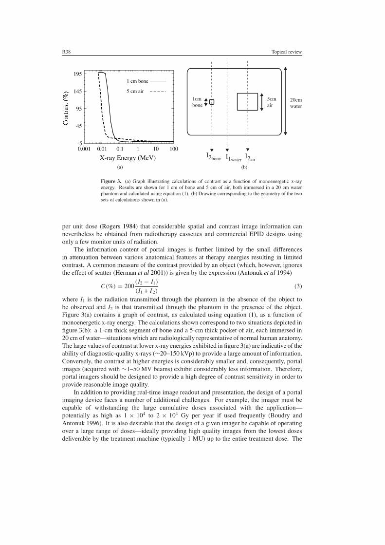
Figure 3. (a) Graph illustrating calculations of contrast as a function of monoenergetic x-rayenergy. Results are shown for 1 cm of bone and 5 cm of air, both immersed in a 20 cm waterphantom and calculated using equation (1). (b) Drawing corresponding to the geometry of the twosets of calculations shown in (a).
per unit dose (Rogers 1984) that considerable spatial and contrast image information cannevertheless be obtained from radiotherapy cassettes and commercial EPID designs usingonly a few monitor units of radiation.
The information content of portal images is further limited by the small differencesin attenuation between various anatomical features at therapy energies resulting in limitedcontrast. A common measure of the contrast provided by an object (which, however, ignoresthe effect of scatter (Herman et al 2001)) is given by the expression (Antonuk et al 1994)
C(%) = 200(I2 − I1)
(I1 + I 2)(3)
where I1 is the radiation transmitted through the phantom in the absence of the object tobe observed and I2 is that transmitted through the phantom in the presence of the object.Figure 3(a) contains a graph of contrast, as calculated using equation (1), as a function ofmonoenergetic x-ray energy. The calculations shown correspond to two situations depicted infigure 3(b): a 1-cm thick segment of bone and a 5-cm thick pocket of air, each immersed in20 cm of water—situations which are radiologically representative of normal human anatomy.The large values of contrast at lower x-ray energies exhibited in figure 3(a) are indicative of theability of diagnostic-quality x-rays (∼20–150 kVp) to provide a large amount of information.Conversely, the contrast at higher energies is considerably smaller and, consequently, portalimages (acquired with ∼1–50 MV beams) exhibit considerably less information. Therefore,portal imagers should be designed to provide a high degree of contrast sensitivity in order toprovide reasonable image quality.
In addition to providing real-time image readout and presentation, the design of a portalimaging device faces a number of additional challenges. For example, the imager must becapable of withstanding the large cumulative doses associated with the application—potentially as high as 1 × 10⁴ to 2 × 10⁴ Gy per year if used frequently (Boudry andAntonuk 1996). It is also desirable that the design of a given imager be capable of operatingover a large range of doses—ideally providing high quality images from the lowest dosesdeliverable by the treatment machine (typically 1 MU) up to the entire treatment dose. The

Topical review R39
nature of a given imaging technology usually defines a narrow range of dose to the detectorover which the device is capable of generating clinically useful, individual images. For modernEPIDs, this range usually lies somewhere between 1 and 10 MUs. (Of course, with a digitalimaging device, it is often possible, if the hardware allows it, to capture and sum consecutiveimages so as to provide a frame-averaged result—thereby extending the range of operation.)Moreover, it is highly desirable that the quality of the image be limited by the statistical noiseof the x-ray quanta that are detected, rather than by some other competing noise source (suchas noise from the acquisition system electronics). The achievement of such a condition, calledx-ray quantum-limited imaging (or, alternatively, input quantum-limited imaging), implies thatfor the number of x-ray quanta detected, the image quality cannot be improved. Generally,this condition is most challenging to accomplish at low doses since the number of detectedx-rays (and hence x-ray noise) is minimal.
2.2. A brief overview of portal imager technologies and their early development
A considerable amount of ingenuity and innovation has been applied to the design of electronicportal imaging systems since the late 1950s. A summary of the wide variety of technologiesthat have been explored appears in table 1. The organization of this table represents a divisionof technologies into those which involve the generation of light (optical systems) and thosewhich do not (non-optical systems). A further delineation is made between technologiesthat are sensitive to the entire portal radiation field simultaneously (two-dimensional, areadetectors) and linear arrays of detectors that are scanned across the radiation field (one-dimensional detectors). For a given x-ray converter, a configuration providing simultaneousdetection over a two-dimensional area will make more efficient use of the incident radiationthereby generally allowing higher quality images at equivalent or lower doses than for a linearscanning system.
The published literature suggests that the development and use of electronic portal imagersbegan in the 1950s. One pioneering system, used to monitor treatment with 200 kV x-raysin real-time, consisted of an x-ray image intensifier tube whose light output was opticallycoupled via a mirror–lens arrangement to a Vidicon TV camera (Strandqvist and Rosengren1958, Wallman and Stalberg 1958). Another early system, used to monitor treatment withx-rays generated by a 2 MeV Van der Graff accelerator, comprised a fluorescent screen whichwas coupled to an Orthicon camera via a mirror–lens combination (Andrews et al 1958)—an approach later modified through the important addition of a metal plate in front of thefluorescent screen (Benner et al 1962). Interest in the general approach of optically couplinga metal plate/phosphor screen to a camera via a mirror–lens combination, schematicallyillustrated in figure 4, greatly increased following the introduction of relatively modernhardware to the technique by Baily et al 1980. This approach was further developed andrefined through the technical, theoretical and clinical efforts of a number of groups (Leong1986, Shalev et al 1989, Munro et al 1987, 1988, 1990a, 1990b, Ezz et al 1991, Swindell et al1991, Swindell 1991, Radcliffe et al 1993, Bissonnette et al 1994, Jaffray et al 1995a, 1995b,Bissonnette et al 1997a, 1997b, Drake et al 2000). These efforts, and those of others,stimulated the widespread commercialization of camera-based EPIDs starting from the late1980s.
A variety of interesting variations on the basic camera-based system illustrated in figure 4have been developed. One approach, which was commercially available for a time, involvedthe use of fibreoptic bundles to transport the light emitted by the metal plate/phosphor screenconverter to a camera, eliminating the mirror and lens and thus reducing the bulk of the

R40
Topicalreview
Table 1. Summary of technologies explored in electronic portal imaging systems. The technologies are divided into optical and non-optical systems and are further divided on the basisof whether they function as a one-dimensional or a two-dimensional detector. For each device, a general description is given along with the nature of the x-ray converting material, theinstitution(s) where the development originated, and informative references, including pertinent review articles. Further references are included in the main text.
Description of system X-ray detector Originating Institution References
Optical systemsTwo-dimensional area detectorsCamera with scintillator
+ x-ray image intensifier Fluorescent screen Chalmers University of Technology (Wallman 1958; review: Munro 1995, 1999)+ mirror + lens Fluorescent screen NCI, Bethesda (Andrews 1958; review: Webb 1993,
Munro 1995, 1999, Herman 2001)+ mirror + lens Metal plate + fluorescent screen University of Goteborg (Benner 1962; review: Boyer 1992,
Webb 1993, Munro 1995, 1999)+ fiber-optic image reducers Metal plate + fluorescent screen Washington University (Wong 1990; review: Boyer 1992, Webb 1993)+ mirror + segmented scintillator Metal plate + segmented CsI(Tl) crystals Royal Marsden (Mosleh-Shirazi 1998)+ mirror + transparent scintillator Transparent CsI(Tl) crystal University of Tennessee (Zeman 1998, Sawant et al 2002)
Indirect detection, active matrix Metal plate + GdO2S2:Tb screen University of Michigan (Antonuk 1991a, 1992a, 1998a;flat-panel array review: Boyer 1992, Munro 1995, 1999,
Antonuk 1998b)One-dimensional scanning detectorsScintillation crystal-photodiode detector ZnWO4 crystals Royal Marsden (Morton 1988, Morton 1991; review: Boyer 1992,
Webb 1993)Scintillation crystal-photodiode detector CsI(Tl) crystals Royal Marsden (Symonds-Tayler 1997)
Non-optical systemsTwo-dimensional area detectorsGas electron multiplier Metal plates Karolinska Institutet (Brahme 2000, Ostling 2000, Iacobaeus 2001)One-dimensional scanning detectorsHigh-voltage rectifier diode array Pb strip + diodes Johns Hopkins (Taborsky 1982, Lam 1986, 1987;
review: Boyer 1992, Webb 1993)Photovoltaic detector array CdTe diodes RMD + MGH (Entine 1992, 1993)Matrix liquid ionization chamber Metal plate + iso-octane NKI (Meertens 1985, van Herk 1991;
review: Boyer 1992, Webb 1993,Munro 1995, 1999, Herman 2001)
Kinestatic charge detector ∼100 atm Xe gas University of Tennessee (DiBianca 1997, Samant 1999.)

Topical review R41
Scintilling X-rayConverter
MirrorCamera+lens
CameraControl
Frame Grabber
Display
Light-tight Enclosure
Radiation Source
Collimator
X rays
Figure 4. Schematic illustration of a camera-based EPID with the x-ray detector (a phosphorscreen) optically coupled to the camera using a mirror and lens.
detector (Wong et al 1990, 1993). The merits and disadvantages (including spatial distortionsand non-uniformities created by the fibreoptic bundles) of this approach are discussed in Webb(1993) and Boyer et al (1992). Currently, efforts are being made to significantly increase theefficiency of x-ray detection (and hence the detective quantum efficiency) of camera-basedsystems by replacing the phosphor screen with converters such as a thick, transparent CsI(Tl)crystal (Zeman et al 1998, Sawant et al 2002) or thick, segmented CsI(Tl) crystals (Mosleh-Shirazi et al 1998a, 1998b). These approaches are described in a later section.
Following its initial conception in 1987 by researchers at the University of Michigan andXerox, PARC, an alternative two-dimensional optical technology for electronic portal imaginghas recently been made commercially available after significant research and development.This technology, based on thin-film electronics of the sort used in active matrix, liquid crystaldisplays offers many advantages over existing commercial EPID systems and conventionalradiotherapy film systems including significantly better image quality (Antonuk et al 1991a,1992a, 1998a, 1998b). This approach is discussed in a later section.
In addition to these two-dimensional optical systems, another interesting optical systemapproach involves a one-dimensional detector array that is scanned across the field of view(Morton and Swindell 1987, Morton 1988, Morton et al 1991). This EPID, involving a doublerow of 2 × 64 zinc tungstate (ZnWO4) crystals (each crystal being 5 mm × 5 mm × ∼25 mmthick) to which photodiodes were attached, produced high quality images. The merits anddisadvantages (primarily the relatively long irradiation times required per scan, ∼4 s) of thesystem are discussed in Boyer et al (1992). This system was used for portal imaging andtransit dosimetry studies (Evans et al 1992, Hansen et al 1996). (A variant of the system

R42 Topical review
using a linear array of BGO crystals was designed for megavoltage CT (Lewis et al 1992).)A new version of this form of EPID, in which the ZnWO4 crystals are replaced by a singlerow of 128 CsI(Tl) crystals (each crystal being 0.32 cm × 0.32 cm × 2.5 cm thick) has beendeveloped (Symonds-Tayler et al 1997). This new system offers increased light yield and abetter signal-to-noise ratio and is being used for scatter and transit dosimetry studies (Spieset al 2000, Evans et al 2000).
While the bulk of efforts to develop optical EPIDs have been directed toward two-dimensional systems, this has thus far not been the case for non-optical systems. Severalnon-optical systems developed in the early 1980s were based on a scanning linear array ofsilicon diodes (Taborsky et al 1982, Lam et al 1986, 1987). The largest such system consistedof 256 high-voltage rectifier diodes (each diode being 0.5 mm thick) arranged in a single rowwith a 2 mm spacing. An ∼1.1 mm layer of Pb was positioned over the diode array and theapparatus was scanned in 2 mm steps across the field. This system and its disadvantages (poorspatial resolution and very large doses required to generate a single image) are summarized inBoyer et al 1992. A similarly configured scanning system, developed by Radiation MonitoringDevices (RMD) and the Massachusetts General Hospital (MGH), utilized a linear array of256 cadmium telluride (CdTe) photovoltaic diodes (Entine et al 1992, 1993). In a prototypesystem, each diode had a dimension of 2 mm × 2 mm × 2 mm. Compared to the silicon diodesof the previous system, these high atomic number, high density, relatively thick diodes offersignificantly improved x-ray detection efficiency allowing the prototype system to providehigh contrast images at significantly shorter scanning times. A scanning system basedon a two-dimensional matrix ionization chamber was developed at the Nederlands KankerInstituut (NKI) starting in the mid-1980s (Meertens et al 1985, Van Herk and Meertens 1987,1988, Van Herk 1991, Van Herk et al 1992, Meertens et al 1990). This system has beencommercially available since 1990 and, like the camera–mirror–lens-based systems using ametal plate/phosphor screen, produces images with significant amounts of clinically usefulinformation. Both systems are more fully discussed in the next section.
Recently, two other novel, non-optical approaches for EPID design have beenexplored. A one-dimensional scanning system employing the kinestatic charge detectionprinciple (DiBianca and Barker 1985) is under development at the University of Tennessee(DiBianca et al 1997, Samant et al 1999). In addition, a dual-energy (keV and MV) two-dimensional imager consisting of multiple gas-electron-multiplier detectors is underdevelopment at the Karolinska Institutet (Brahme et al 2000, Ostling et al 2000,Iacobaeus et al 2001). Each of these approaches is discussed in a later section.
3. First generation EPIDs in routine clinical use
As described above, among the many EPID technologies explored since the 1950s, only threeapproaches provided adequate amounts of clinically useful information and were sufficientlypractical that they have been commercialized and widely adopted. Two of the approaches(camera–mirror–lens-based systems and the scanning matrix ionization chamber design) havebeen in widespread use for over a decade and represent the first generation of practical,commercially-available portal imaging technologies. These approaches are discussed ingreater detail in the present section. A third approach (active matrix, flat-panel imagers),presently being introduced commercially, is described in the next section.
3.1. Camera–mirror–lens-based EPID systems using a metal plate/phosphor screen
As described previously, this approach has been under continuous, incremental developmentsince the 1950s by a wide variety of investigators and institutions (Strandqvist and Rosengren

Topical review R43
1958, Wallman and Stalberg 1958, Andrews et al 1958, Benner et al 1962, Baily et al 1980,Leong 1986, Shalev et al 1989, Munro et al 1987, 1988, 1990a, 1990b, Ezz et al 1991,Swindell 1991, Swindell et al 1991, Radcliffe et al 1993, Bissonnette et al 1994, Jaffray et al1995a, 1995b, Bissonnette et al 1997a, 1997b, Drake et al 2000).
As illustrated in figure 4, the approach involves the use of an x-ray converter that isoptically coupled to a camera by means of a mirror and a lens. The converter consists ofa flat metal plate (typically an ∼1 to 1.5 mm copper, steel or brass plate) and a gadoliniumoxysulfide (Gd2O2S:Tb) phosphor screen. The metal plate serves to convert incident primaryx-rays into high energy electrons, some of which escape the plate into the phosphor, as wellas to block low-energy, scattered radiation which would otherwise reduce the contrast of theimaging system. The phosphor serves to convert primary x-rays into high-energy electronsand transforms a fraction of the energy of the high-energy electrons passing through it intolight. Some of the light diffuses through the screen, exiting on the mirror side. The cameraand lens serve to capture a fraction of this emerging light and transform it into a video signalthat is then sent to other hardware for digitization, processing, display and archiving. It isestimated that, depending on the thickness of the phosphor and the energy of the radiotherapybeam, on the order of only ∼2–4% of the incident x-rays interact and generate measurablesignal in such systems (Herman et al 2001).
Given the large amounts of radiation associated with radiotherapy treatments, theelectronics of the camera would quickly degrade if they were routinely exposed to the directbeam. For this reason, a mirror set at a 45◦ angle serves to direct the light out of the radiationfield towards the camera. The lens serves to collect a fraction of the light emitted by thephosphor and focus it on the surface of the camera sensor. The optical components areenclosed in a light-tight housing to exclude light signal from sources other than the phosphor.
A major advantage of this approach is that the converter can cover all (or at least a verylarge fraction) of the portal field and the camera can sense the light signal from the entireconverter simultaneously. Consequently, all of the radiation passing through the patient andincident upon the converter has the potential of generating signal in the camera and clinicallyuseful images can be produced with as few as a couple of monitor units. A secondary, thoughimportant, practical advantage is that such systems can be assembled from relatively common,commercially available components. As a result, the system has been made available by anumber of manufacturers (Munro 1995, Herman et al 2001). Pictures of commercial camera-based EPIDs are shown in figure 5.
One disadvantage of this approach is that the optical components and their light-tighthousing are relatively bulky and present an encumbrance in the vicinity of where the therapistsset up the patient. Moreover, mounting such systems on treatment machines with beamstoppers presents practical problems. The major disadvantage of the approach is that theoptics of the system only allow those light photons emerging from the phosphor within asmall cone subtended by the lens of the camera to generate signal in the camera (Munro1995). As a result, only 0.1–0.01% of the light emerging from the phosphor reaches thesensor of the camera (Munro 1995)—an effect which reduces image quality as explainedbelow. A fraction of the light that fails to reach the camera causes another image degradingeffect. As described elsewhere (Munro et al 1998b, Munro 1999), some of the light emittedby the screen can reflect from the mirror so as to re-scatter from the phosphor screen andreach the camera. This signal then appears to have come from one part of the screen when,in fact, it originated from another part. This spurious signal, known as glare, can be morethan 25% of the total measured signal, reducing contrast and complicating efforts to use theimager information for quantitative purposes such as transit dosimetry (Heijmen et al 1992,1995).

R44 Topical review
(a) (b)
(c) (d)
Figure 5. Photos of several commercial camera–mirror–lens-based systems using a metalplate/phosphor screen. Three systems mounted on a treatment machine: (a) Elekta ‘iView’system (formerly sold by Philips and Elekta-Philips). (b) Cablon ‘Theraview’ system (formerlysold by Infimed)—shown in the retracted position when not in use. (c) Siemens ‘Beamview’system. One system mounted on a stand like those used for film cassettes: (d) Eliav‘PORTpro’ system. Illustrations for (a) and (c) are taken from Munro (1995) (reprinted withpermission from Harcourt). Technical specifications of these systems are listed in Herman et al2001.
The effect on image quality of the low light collection efficiency of the optical chain ofcamera-based EPIDs has been clearly elucidated through an analysis of the imaging situation(Bissonnette et al 1997b). This analysis is based on the cascaded systems formalism describedin Cunningham et al (1994). In this formalism, an x-ray imager is represented by a seriesof ‘stages’ through which the imaging quanta pass. The stages may be of two types: (i)a gain stage in which the number or statistical distribution of imaging quanta changes (e.g.

Topical review R45
incident x-rays interacting and creating high-energy electrons) and (ii) a spreading stage inwhich some physical process causes blur in the image (e.g. the scattering of light quanta ina phosphor screen). The physical transfer properties of these stages are quantified in termsof gain, spreading and noise parameters. For a given stage, the average number of imagingquanta per incident x-ray is given by the product of the gains up to and including that stage—aconcept which is further generalized to the spatial frequency domain in the formalism. In asimple interpretation, the stage that has the lowest cumulative gain is said to be the ‘quantumsink’. For a given x-ray imaging system, the stage at which the incident x-ray quanta interactin the converter (typically the first stage) is considered the ‘primary’ quantum sink (also calledthe x-ray quantum sink). The cumulative gain of this stage (given simply by the x-ray quantumdetection efficiency) sets an absolute upper limit on the magnitude of the DQE. However, if thelowest cumulative gain occurs in a later stage, this represents a ‘secondary’ quantum sink andthe magnitude of the DQE will be further reduced. In Bissonnette’s analysis (Bissonnette et al1997b), it is shown that the DQE performance of camera–mirror–lens-based EPID systemsusing a metal plate/phosphor screen is limited at lower frequencies (less than 0.25 cycles/mm)by both the primary quantum sink and by a secondary quantum sink in the number of detectedoptical quanta while performance at higher frequencies is limited by this secondary quantumsink.
Considerable empirical and theoretical research has been directed toward optimizing theperformance of conventional camera–mirror–lens-based EPID systems. While this topic isadequately covered elsewhere (Webb 1993), a few efforts merit brief mention. For example,variations in the thickness or geometry of the metal plate and/or the phosphor screen havebeen studied in order to understand the effect upon DQE (Munro et al 1990b, Radcliffe et al1993, Wowk et al 1993, 1994, Jaffray et al 1995a, Bissonnette et al 1997a). The situation iscomplicated (Herman et al 2001): thicker metal plates stop more x-rays but do not necessarilylead to more electrons entering the phosphor; thicker phosphor screens stop more x-raysand generate more light signal but degrade spatial resolution. In addition, the use of a largeaperture lens improves the optical transfer efficiency (Munro et al 1990b) but such large lensesintroduce spherical aberrations (which reduce spatial resolution) and distortion, among othereffects (Herman et al 2001). An alternative strategy to partially compensate for poor lightcollection efficiency involves the reduction of system noise so as to improve the signal-to-noise ratio. This has been explored through extended integration of the light signal on thesensor of the camera (as opposed to digital averaging of frames acquired at the normal videorate) (Munro et al 1990b). Another noise reduction strategy involving the introduction of acooled, low noise CCD camera improves imager performance to the point that the system isx-ray quantum limited at low spatial frequencies (Drake et al 2000). Yet another approach toimproving the performance of camera–mirror–lens-based systems involves the incorporationof a high-gain camera (incorporating avalanche-multiplication) so as to reduce the relativeimportance of the camera noise (Pang and Rowlands 2000). As a result of such efforts,the maximum DQEs achieved for camera–mirror–lens-based EPID systems using a metalplate/phosphor screen are reported to be as high as ∼1%.
3.2. Scanning matrix ionization chamber EPID
Like the camera–mirror–lens-based systems described above, the EPID system based ona scanning matrix ionization chamber conceived and developed at the Nederlands KankerInstituut (NKI) has been commercialized and widely adopted. Compared to camera-basedsystems whose development spanned more than three decades prior to the introductionof the first commercial systems in the late 1980s, the NKI system was developed overa relatively brief period in the 1980s prior to becoming commercially available in 1990

R46 Topical review
(Meertens et al 1985, Van Herk and Meertens 1987, 1988, Van Herk 1991, Van Herk et al1992, Meertens et al 1990).
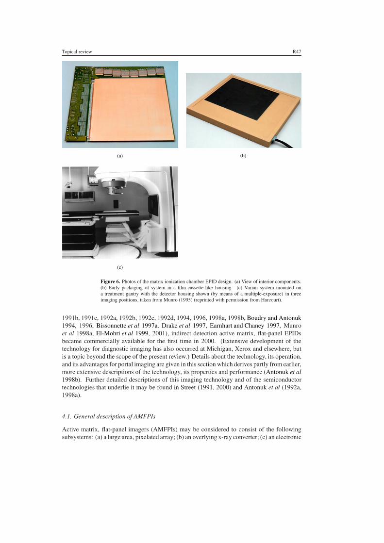
The approach involves the use of a liquid ionization chamber formed by two planes ofelectrodes separated by a 0.8 mm gap. The gap is filled with a fluid (2,2,4-trimethylpentane)which acts as an ionization medium when the chamber is irradiated. Each electrodeplane consists of 256 parallel wires spaced 1.27 mm apart. The electrodes on the twoplanes are oriented perpendicularly to each other thereby forming a matrix of 256 ×256 ionization cells that provide a detection area of 32.5 × 32.5 cm2. In addition, a1 mm thick plastoferrite plate positioned over the ionization chamber serves the samepurpose as the metal plate in camera-based systems—to convert primary x-rays into highenergy electrons, some of which escape into the ionization medium, and to block low-energy, scattered radiation. The ionization medium also serves to convert primary x-raysinto high-energy electrons and, analogous to the phosphor screen in some camera-basedsystems, transforms a fraction of the energy of the high-energy electrons passing throughit into a measurable (ion) signal. A high-voltage supply is used to apply a 300 Vbias to each electrode individually on one of the planes (the high voltage plane). Theelectrodes on the other plane (the signal plane) are individually connected to electrometers.The entire imager consists of the matrix ionization chamber, a 256-channel high-voltageswitching system, a 256-channel electrometer, and control electronics. The chamber andperipheral electronics can be packaged compactly, as shown in figures 6(a), (b) and (c).
Full resolution readout of the imager is achieved by applying the high voltage to each ofthe electrodes on the high voltage plane in succession (for about 20 ms) and recording thesignal generated in each of the 256 electrodes—a process requiring about 5.5 s for readoutof the full imager. A faster (but lower resolution) readout mode is accomplished throughapplication of the high voltage to pairs of electrodes for 10 ms resulting in a 1.5 s readouttime for the full imager. More recent systems operate at 500 V bias with 5 ms per electrodeallowing a total readout time of 1.25 s (Herman et al 2001).
Important advantages of this system include the compactness of the detector, approachingthat of a film cassette, and the lack of geometric distortions in the image. The most significantdisadvantage of this approach is that the utilization of incident x-ray quanta is inferior tothat of a true area detector since, for full-resolution readout, only a single electrode on thehigh voltage plane is switched on at a time. This undesirable situation is somewhat improvedby the fact that the rate of ion recombination in the 2,2,4-trimethylpentane is, even in theabsence of high voltage, relatively slow (∼0.5 s). As a consequence, signal measured fromany given ionization cell during the 5 to 20 ms application of high voltage contains informationabout x-ray interactions in the previous ∼0.5 s, improving the utilization of the incident x-rayquanta. Nevertheless, this effective integration time of ∼0.5 s is still short compared to thetotal image acquisition time and thus a significant amount of incident radiation generates nouseful signal. As a result, while ∼1.5% of the incident x-rays interact in the plastoferrite plateand liquid ionization medium and generate measurable signal (Herman et al 2001), the DQEof the system is, at best, only on the order of 0.5% due to the signal loss in sampling (Van Herk2001). Consequently, the total dose required to generate an image is larger than that forEPIDs incorporating true area detection. In addition, the sampling frequency of the detectionelements of this system is lower than that for the other commercially-available EPIDs.
4. Active matrix, flat-panel imager (AMFPI) EPIDs
Following extensive research and development efforts at the University of Michigan, XeroxPARC and elsewhere starting in 1987 (Street et al 1990, Antonuk et al 1990a, 1990b, 1991a,
Topical review R47
(a) (b)
(c)
Figure 6. Photos of the matrix ionization chamber EPID design. (a) View of interior components.(b) Early packaging of system in a film-cassette-like housing. (c) Varian system mounted ona treatment gantry with the detector housing shown (by means of a multiple-exposure) in threeimaging positions, taken from Munro (1995) (reprinted with permission from Harcourt).
1991b, 1991c, 1992a, 1992b, 1992c, 1992d, 1994, 1996, 1998a, 1998b, Boudry and Antonuk1994, 1996, Bissonnette et al 1997a, Drake et al 1997, Earnhart and Chaney 1997, Munroet al 1998a, El-Mohri et al 1999, 2001), indirect detection active matrix, flat-panel EPIDsbecame commercially available for the first time in 2000. (Extensive development of thetechnology for diagnostic imaging has also occurred at Michigan, Xerox and elsewhere, butis a topic beyond the scope of the present review.) Details about the technology, its operation,and its advantages for portal imaging are given in this section which derives partly from earlier,more extensive descriptions of the technology, its properties and performance (Antonuk et al1998b). Further detailed descriptions of this imaging technology and of the semiconductortechnologies that underlie it may be found in Street (1991, 2000) and Antonuk et al (1992a,1998a).
4.1. General description of AMFPIs
Active matrix, flat-panel imagers (AMFPIs) may be considered to consist of the followingsubsystems: (a) a large area, pixelated array; (b) an overlying x-ray converter; (c) an electronic

R48 Topical review
Array
Readout Control Circuitry
Digital Control Logicand Interface
Data Links
Cassette Enclosure
Signal Processing Circuirty
X-ray converter
Host Computerand Information System
Archival
Figure 7. Schematic illustration of the elements of an active matrix, flat-panel imager (AMFPI).Adapted from Antonuk et al (1998b) (reprinted with permission from AAPM).
acquisition system which controls the operation of the array and extracts and processes analogsignals from the array pixels and (d) a host computer and information system which sendscommands to, and receives digital pixel data from the acquisition system as well as processes,displays, and archives the resulting digital images. These elements are illustrated schematicallyin figure 7.
The distinguishing feature of AMFPI technology is the array which consists of an ∼1 mmthick glass substrate on which thin-film electronic circuits reside. These circuits arecreated through a series of semiconductor processing steps involving plasma enhanced,chemical vapor deposition (PECVD), etching and passivation—typically involving 5–10 setsof photolithographic masks. A schematic illustration of a portion of an array and its external,peripheral control and processing circuits is given in figure 8. By definition, each pixel inan active matrix array incorporates a thin-film switch connected to some form of capacitiveelement. The pixels are organized in a two-dimensional grid and the conductivity of the pixelswitches is controlled through variation of the voltage of control lines with each control lineconnected to all of the pixel switches in a single row. (The control lines are often calledgate control lines for array designs incorporating a pixel switch consisting of a thin-filmtransistor—see below.) During imager operation, the pixel switches are generally kept non-conducting so that charge generated directly or indirectly by incident radiation interacting inan overlying x-ray converting material is integrated in the capacitive element of each pixel.Readout of these imaging signals from the capacitive elements is accomplished by renderingthe pixel switches conducting. Typically, one row of pixels is read out at a time for maximumspatial resolution, although multiple rows can be read out at a time for faster readout at lowerresolution. When the pixel switches along a given row are made to conduct, imaging signalsstored in the pixels are sampled by external peripheral electronics by means of data lines, witheach data line connected to all the pixel switches in a given column. The action of readingout the pixels also reinitializes them—although additional initialization steps may be requireddepending on the type of switch and the nature of the converter. The general organizationof these imaging arrays is parallel to that of active matrix liquid-crystal displays (AMLCDs,commonly used for laptop computers) which also employ a two-dimensional ‘active matrix’of thin-film switches to control the output of light allowing the display of images.
4.2. Description of different AMFPI designs for portal imaging
The pixel switches thus far employed for the majority of AMFPI designs are thin-film transistors (TFTs) fabricated from hydrogenated amorphous silicon (a-Si:H). (While

Topical review R49
Gate ControlLines for Pixel
Switches
DataLines
Pixel
Contact for GateControl Line
Glass SubstrateBoundary
Contact forData Line
PixelSwitch
Pixel CapacitiveElement
External ChargeSensitive Preamplifier
Con
trol
Cir
cuitr
yfo
r Pi
xel S
witc
hes
Figure 8. Schematic illustration of a corner of an indirect or direct detection active matrix, flat-panel imaging array illustrating the matrix addressing scheme of such designs. Also illustratedis external peripheral control circuitry that is connected to the array via peripheral contacts—onecontact for each gate control line and each data line. This circuitry controls the conductivity of thepixel switches and amplifies the pixel signals. As an example, the pixel switches are representedas TFTs but diode-based switches are also used in some diagnostic imager designs. The capacitiveelement depicted for each pixel in the figure corresponds to a photosensor for an indirect detectionarray and a storage capacitor for a direct detection array. Adapted from Antonuk et al (1998b)(reprinted with permission from AAPM).
considerable effort has also been devoted to the development of pixel switches based on asingle, or a pair of a-Si:H diodes, this has thus far been restricted to some imagers designedfor diagnostic radiographic imaging.) Concerning the conversion of incident x-ray energyinto charge stored in the capacitive element in each pixel, two general approaches can bedistinguished based on how this imaging signal is generated and stored in the pixels. Indirectdetection AMFPIs use an x-ray converter consisting of a combination of a metal plate and ascintillator—with the scintillator positioned directly over the photosensor integrated into thearray. In this approach, some of the radiation-induced light escapes the scintillator in thedirection of the photosensor. Light entering the photosensor is converted into electron–holepairs, one electron–hole pair per detected light photon. The structure of the photosensoralso forms the capacitive element in each pixel where this signal is stored until readout.Direct detection AMFPIs use an x-ray converter consisting of a combination of a metalplate and a photoconductor—with the photoconductor electrically coupled to a separatecapacitor built into each pixel. In this approach, the radiation generates electron–holepairs in the photoconductor and this imaging signal is stored in the pixel capacitors untilreadout.
4.3. Indirect detection active matrix flat-panel EPIDs and their advantages
Thus far, commercial EPID systems incorporating active matrix flat-panel arrays are basedsolely on the indirect detection approach. In these systems, the photosensor is a discrete a-Si:Hphotodiode located in each pixel. (Recently, a continuous a-Si:H photodiode structure hasbeen developed that increases the optical fill factor of the arrays, i.e. the fraction of the pixelthat is sensitive to light from the scintillator (Mulato et al 2001). Although such structures

R50 Topical review
could conceivably appear in commercial megavoltage imaging arrays in the future, increasingthe optical fill factor is generally an issue only for arrays designed for considerably higherresolution applications.) The scintillator incorporated in present commercial systems is aphosphor screen, although columnar CsI(Tl) is likely to be explored for portal imaging in thefuture. Columnar CsI(Tl) is popular for diagnostic imaging applications as its needle-likestructure assists in confining the lateral spread of light as the thickness of the scintillatorincreases, thus preserving spatial resolution. Figures 9(a) and (b) schematically illustrate sideviews of pixels incorporating each of these scintillator types. In addition, for the TFT +photodiode array designs used for portal imaging, the action of reading out the pixels alsoreinitializes them.
Specifications of commercial EPIDs based on active matrix technology are given intable 2. The first commercial system was introduced by Varian Medical Systems in 2000 andoffers a 30 × 40 cm2 detection area. (An earlier commercial alpha-prototype produced bythis company was based on an array with a 26 × 26 cm2 detection area developed earlierfor radiotherapy research by Michigan and Xerox, PARC (Antonuk et al 1995, 1998a).)A second commercial EPID based on the same technology was introduced by Elekta OncologySystems in mid-2001 and offers a 41 × 41 cm2 detection area. Finally, a prototype imagerbased on this technology from Siemens Medical Systems with a 41 × 41 cm2 detection areais presently undergoing clinical evaluation. Pictures of two of these imagers are shown infigure 10. Based on studies of a research prototype of similar design (El-Mohri et al 2001), theDQE of such systems when operated with an ∼133 mg cm−2 phosphor screen is anticipatedto be slightly greater than 1% at 6 MV.
Indirect detection AMFPIs offer a variety of advantages for the portal imaging application.This solid state technology facilitates the creation of compact detectors (as illustrated infigure 10) offering real-time, digital readout. The technology also allows the creationof very large-area arrays which dwarf the largest commercially available, pixel-basedcrystalline-silicon imaging structures, namely, charge-coupled device (CCD) arrays with asensitive area of ∼8 × 8 cm2. By comparison, monolithic active matrix flat-panel arrays aslarge as 41 × 41 cm2 have thus far been produced (table 2). If required by the application,even larger detectors should be possible, for example, through tiling of two or four arrays(Colbeth et al 1997). The arrays and their acquisition systems may be designed to provideboth radiographic readout (i.e. capture of single frames) or fluoroscopic readout (e.g. up to 30frames per second (Antonuk et al 1993)). The signal response of the pixels is highly linear(Antonuk et al 1998a) and the technology can be configured for dosimetric measurements(El-Mohri et al 1999, McCurdy et al 2001). Moreover, the a-Si:H TFTs and photodiodesare highly resistant to radiation damage (Antonuk et al 1990b, Boudry and Antonuk 1994,1996)—even at the very high doses to which a portal imager could be exposed (in excess of104 Gy per year). Of course, attention must also be paid to the issue of radiation damage tothe readout circuits located around the periphery of the arrays.
Perhaps one of the most important advantages of AMFPI technology for portal imagingis the high degree of image quality. For example, given: (a) that the array photodiodes are inclose proximity to the scintillator; (b) that a large fraction of the pixel area is occupied by thephotodiode for arrays designed for portal imaging; (c) the high efficiency of conversionof light entering the photodiodes into electron-hole pairs and (d) the high efficiency ofreadout of the signal from the pixels; then AMFPI-based EPIDs are capable of using onthe order of 50% of the light emitted from the scintillator. This value is several ordersof magnitude larger than optical transfer efficiencies for camera–mirror–lens-based systems.Consequently, secondary quantum sinks in the number of detected optical quanta, which limitthe performance of camera-based EPIDs, are absent in AMFPI-based EPIDs allowing this

Topical review R51
X-Ray
Pixel Switch
CsI (Tl) Converter
Metal Plate
Pixel Photodiode − Storage Capacitor
(b)
Converting Phosphor
Converting Phosphor
X-Ray
Pixel Switch
Photoconductor
Bias electrode
Metal Plate
Pixel Storage Capacitor
Collection Electrode
(c)
X-Ray
Pixel Switch
(a)
Metal Plate
Pixel Photodiode − Storage Capacitor
Converting Phosphor
Figure 9. Schematic illustration (not to scale) of x-ray detection in an AMFPI for (a) and (b)indirect detection using a phosphor and a columnar CsI(Tl) scintillator, respectively; and (c) directdetection of the incident radiation. In each case, the x-ray converter over a single pixel is illustrated.Taken from Antonuk et al (1998b) (reprinted with permission from AAPM).
technology to offer x-ray quantum limited imaging (Munro and Bouius 1998a, El-Mohri et al2001). The close proximity of the photodiodes to the scintillator also sharply limits oreliminates glare in AMFPIs—a problem for camera–mirror–lens-based systems. Moreover,

R52 Topical review
Table 2. Specifications of commercial imagers based on indirect detection, active matrix flat-panelimaging technology. Information not available at the time of publication is so indicated. Forthe Varian system, the asterisk refers to the fact that the pixel format and pixel-to-pixel pitch ofthe array are actually 1024 × 768 pixels and 392 µm, respectively, while the system is presentlyconfigured to provide readout at a lower resolution.
Company Varian Medical Systems Elekta Oncology Systems
Product PortalVision aS500 iViewGTCommercial availability 2000 2001Detector area 40.14 × 30.11 cm2 40.96 × 40.96 cm2
Array format Monolithic array Monolithic arrayPixel format 512 × 384∗ 512 × 512Pixel pitch 784 µm∗ 800 µmMaximum image acquisition rate 10 frames per second 3 frames per second
(frames averaged in hardware)Image display and storage rate 2 seconds per image ∼0.3 seconds per imageDigitization 14 bits 16 bitsMetal plate 1 mm Cu 1 mm CuScintillator 133 mg cm−2 Gd2O2S:Tb Gd2O2S:TbMiscellaneous Neutral density filter n/a
preliminary studies comparing AMFPI-based and matrix-ionization-chamber-based EPIDsstrongly suggest superior image quality from the AMFPIs (Van Herk 2001). Finally, anobserver-based contrast-detail study comparing an AMFPI-based EPID and portal film systems(the current gold standard in portal imaging) indicate that AMFPIs offer performance superiorto that of a conventional portal imaging film system (Antonuk et al 1998). Moreover, thiswas true even when images made with the AMFPI used less radiation than the film system.Furthermore, in a comparison between the AMFPI and the EC-L portal film system, the levelsof performance were found to be similar, although this was true only over a very narrowrange of exposure in which the EC-L film was neither under- nor over-exposed. These earlystudies suggest that AMFPIs may offer considerable improvements in portal imaging qualitycompared to present commercial systems.
An illustration of the image quality to be expected from an AMFPI-based EPID is shownin figure 11. (Images from earlier EPID systems appear throughout the literature, e.g. in theprior reviews cited in section 1.3.) The images in figure 11 were obtained radiographicallyand are of the pelvic region of a single patient (Antonuk et al 1998a). Single exposure imagesobtained at 6 and 15 MV at exposures of 4 and 3 MU are shown in figures 11(a) and (b),respectively. In addition, figures 11(c) and (d) show double-exposure AMFPI images taken at6 and 15 MV, respectively, each of which consists of a pair of images captured in the presenceand absence of a shaped collimation block, and then digitally added. The double-exposureimages were acquired at the lowest available dose setting (1 MU for each individual image).For purposes of comparison, images of the same patient taken with a standard radiotherapyfilm cassette, double-exposed in the conventional manner, at doses corresponding to those usedin routine clinical practice are shown for 6 and 15 MV in figures 11(e) and (f ), respectively.The image processing of the AMFPI images was minimal and consisted of simple gain andoffset corrections, filtering to eliminate the distracting influence of pixel and line defects, andwindow and level adjustments of the digital data. The films were digitized and subject to moreextensive processing in order to maximize the presentation of information content that wouldotherwise be obscured due to the logarithmic response of the film.

Topical review R53
(a)
(b)
Figure 10. Photos of two indirect detection, active matrix flat-panel systems. (a) PortalVisionaS500 from Varian Medical Systems. (b) iViewGT from Elekta Oncology Systems with thedetector box shown (by means of a multiple-exposure) in various stages of retraction toward thetreatment gantry. See table 2 for related design specifications. Photos courtesy of Ed Shapiro andKevin Brown.

R54 Topical review
(a) (b)
(c) (d)
(e) (f )
Figure 11. Radiographic images acquired in the pelvic region of a patient (Antonuk et al 1998a;reprinted with permission from Elsevier Science). The images were acquired with a prototypeindirect detection AMFPI under conditions of (a) single exposure—6 MV, 4 MU; (b) singleexposure—15 MV, 3 MU; (c) double-exposure—6 MV, 1 + 1 MU (i.e. 1 MU with a shapedcollimation block and 1 MU without the block in place); and (d) double-exposure—15 MV, 1 +1 MU. The AMFPI incorporates a 508 µm pitch, 512 × 512 pixel array and uses a 1 mm Cumetal plate and a 70 mg cm−2 Gd2O2S:Tb phosphor screen. Double-exposure images acquiredwith a standard radiotherapy film cassette under conditions of (e) 6 MV, 3 + 3 MU and (f ) 15 MV,4 + 4 MU.

Topical review R55
The single exposure images obtained with the AMFPI system (figures 11(a) and (b))demonstrate excellent contrast resolution and provide sufficient anatomical detail to allowconfident localization. Even at 15 MV, image quality is only somewhat reduced compared to6 MV. Moreover, despite the minimal doses used in the AMFPI double-exposure images(figures 11(c) and (d)), they compare quite favourably with the film images (figures 11(e)and (f )) that were taken at higher doses. Images such as those shown in the figures give anindication of the quality provided by the current gold standard, film, and the potential of therelatively recent AMFPI EPID technology.
4.4. EPIDs based on direct detection active matrix flat-panel technology
Although commercially available active matrix flat-panel EPIDs are exclusively based onindirect detection, it is likely that direct detection AMFPIs will be thoroughly explored forportal imaging given their commercial availability for diagnostic imaging. In the directdetection approach, a continuous layer of photoconductive material is deposited over thesurface of the array (Zhao and Rowlands 1995). In this case, each pixel has an auxiliarystorage capacitor connected to the pixel switch as well as to a collection electrode that servesto gather signal from the photoconductor. A likely configuration for the portal imagingapplication is illustrated in figure 9(c) which schematically illustrates a side view of a directdetection pixel incorporating an overlying metal plate and continuous photoconductive layer.
Thus far, the only photoconductor used in commercial AMFPIs for diagnostic imagingis amorphous selenium (a-Se) with thicknesses up to ∼1000 µm (Tsukamoto et al 1999,Adachi et al 2000, Choquette et al 2000). (Other materials such as lead iodide (PbI2), mercuriciodide (HgI2), and cadmium telluride (CdTe) are also under examination for diagnostic imaging(Street et al 2001, Adachi et al 2000).) Given that 1000 µm of a-Se would have an estimatedx-ray quantum detection efficiency of ∼3% for a 6 MV beam, the use of this material ina direct detection AMFPI for portal imaging would be of interest. Early studies of the useof a-Se for portal imaging have been reported (Falco et al 1998, Lachaine and Fallone 1998,Lachaine et al 2001, Mah et al 1998, 1999, Pang et al 2001) and interest in this material islikely to continue.
5. Contemporary research toward improving EPID performance
In recent years, a number of efforts have been made to explore new technologies for electronicportal imaging devices or attempt to address weaknesses in existing technologies (Mosleh-Shirazi et al 1998a, 1998b, Zeman et al 1998, Sawant 1999, Sawant et al 2002, DiBianca et al1997, Samant et al 1999, Brahme et al 2000, Ostling et al 2000, Iacobaeus et al 2001). In thissection, we shall briefly outline these ongoing research activities which are largely focused onimproving the efficiency of detection of the incident primary x-ray radiation.
One particular direction of these research efforts is to significantly increase the x-rayquantum detection efficiency of camera–mirror–lens-based EPID systems from the presentlow levels of ∼2–4% (Herman et al 2001). Such an effort is being carried out by the JointDepartment of Physics, Institute of Cancer Research and Royal Marsden NHS Trust andinvolves replacing the phosphor screen with a scintillator consisting of a two-dimensionalarray of CsI(Tl) elements (Mosleh-Shirazi et al 1994, 1998a, 1998b). This system has thesame optical geometry as conventional camera-based systems, as illustrated in figure 12(a).The x-ray converter has an area of 45 × 60 cm2 and consists of 100 modules. Each modulecomprises a 15 × 20 array of optically isolated CsI(Tl) detector elements. Each element is3 mm × 3 mm × 10 mm thick (giving an x-ray quantum detection efficiency of ∼18% at 6 MV)

R56 Topical review
Collimator
Radiation Source
X-rays
Object
Mirror
Light
Cs(Tl) Leaded Glass
Camera Lens
CCD Camera
(b)
Figure 12. Schematic illustrations of the optical elements for various geometries used for camera-based EPID systems. (a) Geometry commonly used for conventional camera–mirror–lens-basedsystems using a metal plate/phosphor screen or a metal plate/segmented CsI(Tl) converter.(b) Geometry used for the camera-based system involving a thick CsI(Tl) scintillator underdevelopment at the University of Tennessee, adapted from Sawant et al (2002) (reprinted withpermission from AAPM).

Topical review R57
and is optically separated from neighbouring elements by 0.3 mm gaps filled with titaniumdioxide-loaded epoxy resin. The modules are attached to a 3 mm thick aluminium plate.The converter is positioned 150 cm from the source providing an impressive 30 × 40 cm2
field-of-view at the isocentre. In addition, each radiation pulse leads to a camera frame thatis summed by a frame grabber. The system reportedly allows a 2 mm diameter structure of1.3% contrast and an 18 mm diameter object of 0.125% contrast to be resolved at 6 MV withan ∼1 × 10⁻² Gy irradiation and provides a spatial resolution of ∼2 mm at the isocentre(Mosleh-Shirazi et al 1998b). The authors further report that the system is limited by a lowoptical-coupling efficiency and significant dark current in the CCD camera sensor—limitationswhich they indicate can be largely removed through the use of a cooled, large area CCD anda fast lens.
Another novel approach towards significantly increasing the use of the incident x-rays incamera–mirror–lens-based systems involves replacing the metal plate/phosphor screen with alead-glass plate coupled to a thick, transparent CsI(Tl) scintillator (Zeman et al 1998, Sawant1999, Sawant et al 2002). In this approach, the mirror–lens–camera combination is locatedon the same side as the x-ray source, as illustrated in figure 12(b), rather than on the oppositeside as in conventional systems (figure 12(a)). A plate of ∼1 cm thick transparent lead-glasswith an index of refraction matched to that of CsI(Tl) (1.79) is optically coupled to the frontof the scintillator. This layer, having an x-ray absorption approximately equivalent to that of1 mm of lead, serves to block the scattered radiation which would otherwise reduce the contrastof the system and serves to allow scintillator light to reach the camera. In addition to theseprimary functions, the lead-glass plate also converts some of the incident x-rays into highenergy electrons which escape into the scintillator. The optics of the system are designed toallow light generated by all x-rays interacting along a given incident trajectory to be recordedat a single point on the camera sensor, as illustrated in figure 13. Since light emerging from thescintillator–lead–glass combination is subject to refraction, this optical result can be achievedby collecting the light emerging from the front of the scintillator by placing the camera sensorat an appropriate distance. In the small angle approximation, this distance is given by D
n, where
D is the distance from the x-ray source to the scintillator and n is the index of refraction forCsI(Tl). The primary merit of this EPID design is that it allows the use of a thick scintillator(and thus increased use of the incident x-rays) without significant loss of spatial resolutiondue to spreading and scattering of light photons in the scintillator, as is the case for phosphorscreens. Rather, the spatial resolution of the system is limited by a combination of the spreadof the secondary radiation that produces the light photons and the limited depth of focusof the optics. One configuration that has been examined involved a 12.5 mm thick CsI(Tl)scintillator that provides an x-ray quantum detection efficiency of ∼25% (Sawant et al 2002).While the performance of this proposed system is still limited by a secondary quantum sinkin the number of detected optical quanta (as for most camera-based systems), calculationssuggest that the zero-frequency DQE would be as high as ∼11%. In addition, due to the needto place the mirror in front of the scintillator, the x-ray converter must be located further fromthe source thereby requiring a larger area detector in order to image a given field of view atthe isocentre.
Another approach towards increasing the x-ray quantum detection efficiency for portalimaging involves the use of the kinestatic charge detection (KCD) technique originallydeveloped for diagnostic imagers (DiBianca and Barker 1985). The KCD approach, illustratedin figure 14, involves the use of an x-ray detector that is scanned across the field of view. Thedetector consists of an x-ray detection volume and a signal collection volume. The designof the KCD system under development for portal imaging (DiBianca et al 1997, Samantet al 1999) closely parallels that of a previously developed high-pressure gas-based diagnostic

R58 Topical review
X-raySource
CCD
CsI(Tl)
D/n
D
Figure 13. Schematic diagram illustrating an essential principle of the optics of the camera-basedsystem under development at the University of Tennessee, corresponding to figure 12(b). Inthis diagram, the lead glass plate, the 45◦ mirror and the lens have been omitted for clarity ofpresentation. By gathering light emerging from the front of the CsI(Tl) scintillator on a camerasensor placed at a carefully chosen distance ( D
n), light from x-rays interacting along a given incident
trajectory is recorded at a single point on the sensor. Note that if the camera sensor were placedon the far side of the scintillator (as in conventional camera-based systems, figure 12(a)), the lightfrom x-rays along a given trajectory would be focused along a line on the sensor, rather than on apoint (Sawant et al 2002).
imager (DiBianca et al 1996). In the design, while the detection volume is continuous, thesignal collection volume consists of a linear array of n discrete charge detection elements.Incident x-rays interact and generate charge in the detection volume. An electric field appliedacross this volume drives a portion of this charge toward the signal collection elements thatserve to continuously produce a spatially discrete set of n signals that may be amplified anddigitized. Central to the KCD technique is the fact that the detector is mechanically scannedat a speed equal and opposite to the signal charge drift velocity, in a direction perpendicularto that of the x-ray beam. As illustrated in figure 14(c), this procedure makes the secondaryionization cloud created by the interacting x-rays stationary relative to the coordinate systemof the radiation source. Thus, for a given incident x-ray trajectory, charge is integrated alonga single line in the volume of the detector that is sampled all together by a signal collectionelement. The signal from each collection element is integrated over an appropriate timeinterval, m times per scan, so as to produce an n × m array of numbers which constitutes atwo-dimensional image. Early theoretical studies and empirical studies utilizing a prototypeKCD megavoltage imager with 384 6-cm-deep signal collection elements with an effectivespacing of 400 µm and containing 100 atmospheres of Xe, have been reported (DiBianca et al1997). These studies predict a high x-ray quantum detection efficiency (∼36%) and forecastthat the system would offer high spatial resolution, high contrast resolution, and negligiblescatter acceptance. The authors further indicate that such systems would offer a large field ofview and could be adapted to dual-energy (i.e. diagnostic and megavoltage) imaging.

Topical review R59
X-ray detection Volume
Signal Collection Volume
Scan Direction
Signal ChargeDrift Collection
nn-1.... n-2
X-ray Photon
Secondary Ionization Cloud
Electric Field
Signal Contribution
X-ray Photon
T1T2
T3
Scan Direction
Secondary Ionization Cloud
(a)
(b)
(c)
Figure 14. Schematic diagrams illustrating the kinestatic charge detection (KCD) technique. (a)Diagram of an n-channel KCD illustrating the x-ray detection and signal collection volumes andthe anti-parallel scan and signal charge drift directions. (b) Diagram showing the drift path in theimposed electric field of a secondary ionization cloud produced by an absorbed x-ray photon. (c)Diagram of the integration over time of the charge clouds produced by interacting x-ray photonsincident along a fixed trajectory. The detector moves upward as the time (labeled below) increases.Figure taken from DiBianca and Barker (1985) (reprinted with permission from AAPM).
A novel gas detector concept for portal imaging is in the early stages of development atthe Karolinska Institutet (Brahme et al 2000, Ostling et al 2000, Iacobaeus et al 2001), withthe objectives of increasing the x-ray quantum detection efficiency as well as providing dual-energy imaging. The concept incorporates the use of a gas electron multiplier (GEM)—anamplification structure recently developed by Sauli at CERN (Sauli 1997). The GEM is asimple device that provides efficient multiplication of electrons in a gas detector with a gainon the order of 103–104. One possible configuration for the imager being considered bythe Karolinska group, illustrated in figure 15, consists of a single chamber filled with gas atatmospheric pressure with two parts: an upper part to image diagnostic-energy x-rays and alower part to image megavoltage-energy x-rays. In this realization, diagnostic x-rays interactin a gas converter followed by a GEM. (In an alternate arrangement under consideration, asolid converter would be used in the upper part to provide a higher efficiency for detection
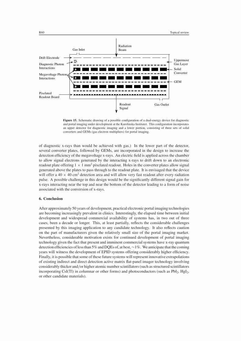
R60 Topical review
PixelatedReadout Board
Radiation Beam
Readout Signal
Gas Outlet
Gas Inlet
UppermostGas Layer
SolidConverter
GEM
Drift Electrode
Diagnostic Photon Interactions
Megavoltage Photon Interactions
Figure 15. Schematic drawing of a possible configuration of a dual-energy device for diagnosticand portal imaging under development at the Karolinska Institutet. This configuration incorporatesan upper detector for diagnostic imaging and a lower portion, consisting of three sets of solidconverters and GEMs (gas electron multipliers) for portal imaging.
of diagnostic x-rays than would be achieved with gas.) In the lower part of the detector,several converter plates, followed by GEMs, are incorporated in the design to increase thedetection efficiency of the megavoltage x-rays. An electric field is applied across the chamberto allow signal electrons generated by the interacting x-rays to drift down to an electronicreadout plate offering 1 × 1 mm2 pixelated readout. Holes in the converter plates allow signalgenerated above the plates to pass through to the readout plate. It is envisaged that the devicewill offer a 40 × 40 cm2 detection area and will allow very fast readout after every radiationpulse. A possible challenge in this design would be the significantly different signal gain forx-rays interacting near the top and near the bottom of the detector leading to a form of noiseassociated with the conversion of x-rays.
6. Conclusion
After approximately 50 years of development, practical electronic portal imaging technologiesare becoming increasingly prevalent in clinics. Interestingly, the elapsed time between initialdevelopment and widespread commercial availability of systems has, in two out of threecases, been a decade or longer. This, at least partially, reflects the considerable challengespresented by this imaging application to any candidate technology. It also reflects cautionon the part of manufacturers given the relatively small size of the portal imaging market.Nevertheless, considerable motivation exists for continued development of portal imagingtechnology given the fact that present and imminent commercial systems have x-ray quantumdetection efficiencies of less than 5% and DQEs of, at best, ∼1%. We anticipate that the comingyears will witness the development of EPID systems offering considerably higher efficiency.Finally, it is possible that some of these future systems will represent innovative extrapolationsof existing indirect and direct detection active matrix flat-panel imager technology involvingconsiderably thicker and/or higher atomic number scintillators (such as structured scintillatorsincorporating CsI(Tl) in columnar or other forms) and photoconductors (such as PbI2, HgI2,or other candidate materials).

Topical review R61
Acknowledgments
I wish to acknowledge the many individuals whose kind assistance made this review paperpossible. Thanks to Peter Munro at the University of Western Ontario and Marcel Van Herkat the NKI for photos of and information on the commercial camera-based and matrixionization chamber systems. Thanks also to Christian Iacobaeus and Janina Ostling fordiscussions concerning the GEM-based system and for providing figure 15. I also wish tothank Ed Shapiro of Varian Medical Systems, Kevin Brown of Elekta Oncology Systems,Don Carlson of Siemens Medical Systems, and Reuven Levinson of Eliav for informationconcerning, and pictures of their companies’ systems. Finally, I wish to express special thanksto members of the flat-panel imaging group at the University of Michigan: to Youcef El-Mohrifor his extensive help with the preparation of the illustrations; to Amit Sawant for valuablediscusssions concerning the systems under development at the University of Tennessee and forproviding figure 13; and to Youcef El-Mohri, Amit Sawant, Kyung-Wook Jee and Qihua Zhaofor their assistance with proof-reading the manuscript. All these contributions were invaluableand any errors or omissions, of which there are bound to be some, are all mine.
References
Adachi S, Hori N, Sato K, Tokuda S, Sato T, Uehara K, Izumi Y, Nagata H, Yoshimura Y and Yamada S 2000Experimental evaluation of a-Se and CdTe flat-panel x-ray detectors for digital radiography and fluoroscopyProc. SPIE 3977 38–47
Andrews J R, Swain R W and Rubin P 1958 Continuous visual monitoring of 2 MeV roentgen therapy Am. J.Roentgenol. 79 74–8
Antonuk L E, Yorkston J, Boudry J, Longo M J, Jimenez J and Street R A 1990a Development of hydrogenatedamorphous silicon sensors for high energy photon radiotherapy imaging IEEE Trans. Nucl. Sci. 37 165–70
Antonuk L E, Boudry J, Yorkston J, Wild C F, Longo M J and Street R A 1990b Radiation damage studies ofamorphous silicon photodiode sensors for applications in radiotherapy x-ray imaging Nucl. Instrum. MethodsA 299 143–6
Antonuk L E, Boudry J, Kim C W, Longo M J, Morton E J, Yorkston J and Street R A 1991a Signal, noise and readoutconsiderations in the development of amorphous silicon photodiode arrays for radiotherapy and diagnostic x-rayimaging Proc. SPIE 1443 108–19
Antonuk L E, Yorkston J, Boudry J, Longo M J and Street R A 1991b Large area amorphous silicon photodiodearrays for radiotherapy and diagnostic imaging Nucl. Instrum Methods A 310 460–4
Antonuk L E, Yorkston J, Kim C W, Huang W, Morton E J, Longo M J and Street R A 1991c Light responsecharacteristics of amorphous silicon arrays for megavoltage and diagnostic imaging Mater. Res. Soc. Symp.Proc. 219 531–6
Antonuk L E, Boudry J, Huang W, McShan D L, Morton E J, Yorkston J, Longo M J and Street R A 1992aDemonstration of megavoltage and diagnostic x-ray imaging with hydrogenated amorphous silicon arrays Med.Phys. 19 1455–66
Antonuk L E, Yorkston J, Huang W, Boudry J, Morton E J, Longo M J and Street R A 1992b Radiation responsecharacteristics of amorphous silicon arrays for megavoltage radiotherapy imaging IEEE Trans. Nucl Sci. 391069–73
Antonuk L E, Yorkston J, Huang W, Boudry J, Morton E J, Longo M and Street R A 1992c Factors affecting imagequality for megavoltage and diagnostic x-ray a-Si:H imaging arrays Mater. Res. Soc. Symp. Proc. 258 1069–74
Antonuk L E, Boudry J, Yorkston J, Morton E J, Huang W and Street R A 1992d Development of thin-film, flat-panelarrays for diagnostic and radiotherapy imaging Proc. SPIE 1651 94–105
Antonuk L E, Yorkston J, Huang W, Siewerdsen J and Street R A 1993 Considerations for high frame rate operationof two-dimensional a-Si:H imaging arrays Mater. Res. Soc. Symp. Proc. 297 945–50
Antonuk L E, Boudry J, Huang W, Lam K L, Morton E J, Ten Haken R K, Yorkston J and Clinthorne N H 1994Thin-film, flat-panel, composite imagers for projection and tomographic imaging IEEE Trans. Med. Imaging 13482–90
Antonuk L E, Boudry J M, El-Mohri Y, Huang W, Siewerdsen J H, Yorkston J and Street R A 1995 Large area,flat-panel amorphous silicon imagers Proc. SPIE 2432 216–27

R62 Topical review
Antonuk L E, Yorkston J, Huang W, Sandler H, Siewerdsen J H and El-Mohri Y 1996 Megavoltage imaging with alarge area, flat-panel, amorphous silicon imager Int. J. Radiat. Oncol. Biol. Phys. 36 661–72
Antonuk L E, El-Mohri Y, Huang W, Jee K-W, Siewerdsen J H, Maolinbay M, Scarpine V E, Sandler H and Yorkston J1998a Initial performance evaluation of an indirect-detection, active matrix flat-panel imager (AMFPI) prototypefor megavoltage imaging Int. J. Radiat. Oncol. Biol. Phys. 42 437–54
Antonuk L E, El-Mohri Y and Jee K-W 1998b Active matrix flat-panel imagers for electronic portal imaging (AMFPIs)Imaging in Radiation Therapy AAPM Medical Physics Monograph no 24 ed John D Hazel and Arthur L Boyer(Medical Physics Publishing) 371–92
Baily N A, Horn R A and Kampp T D 1980 Fluoroscopic visualization of megavoltage therapeutic x-ray beams Int.J. Radiat. Oncol. Biol. Phys. 6 935–9
Benner S, Rosengren B, Wallman H and Netteland O 1962 Television monitoring of a 30 MV x-ray beam Phys. Med.Biol. 7 29–34
Bissonnette J-P, Jaffray D A, Fenster A and Munro P 1994 Optimal radiographic magnification for portal imagingMed. Phys. 21 1435–45
Bissonnette J-P, Cunningham I A and Munro P 1997a Optimal phosphor thickness for portal imaging Med. Phys. 24803–14
Bissonnette J-P, Cunningham I A, Jaffray D A, Fenster A and Munro P 1997b A quantum accounting and detectivequantum efficiency analysis for video-based portal imaging Med. Phys. 24 815–86
Boudry J M and Antonuk L E 1994 Radiation damage of amorphous silicon photodiode sensors IEEE Trans. Nucl.Sci. 41 703–7
Boudry J M and Antonuk L E 1996 Radiation damage of amorphous silicon, thin-film, field-effect transistors Med.Phys. 23 743–54
Boyer A L, Antonuk L, Fenster A, Meertens H, Munro P, Reinstein L E and Wong J 1992 A review of electronicportal imaging devices (EPIDs) Med. Phys. 19 1–16
Brahme A, Danielsson M, Iacobaeus C, Ostling J, Peskov V and Wallmark M 2000 Evaluation of a GEM andCAT-based detector for radiation therapy beam monitoring Nucl. Instrum. Methods A 454 136–41
Choquette M, Rougeot H, Martin J P, Laperriere L, Shukri Z and Polischuk B 2000 Direct selenium x-ray detectorfor fluoroscopy, R&F, and radiography Proc. SPIE 3977 128–36
Colbeth R E, Allen M J, Day D J, Gilblom D L, Klausmeier-Brown M E, Pavkovich J, Seppi E J and Shapiro E G1997 Characterization of an amorphous silicon fluoroscopic imager Proc. SPIE 3032 42–51
Cunningham I A, Westmore M S and Fenster A 1994 A spatial-frequency dependent quantum accounting diagramand detective quantum efficiency model of signal and noise propagation in cascaded imaging systems Med.Phys. 21 417–27
Cunningham I A and Shaw R 1999 Signal-to-noise optimization of medical imaging systems J. Opt. Soc. Am. A 16621–32
DiBianca F A and Barker M D 1985 Kinestatic charge detection Med. Phys. 12 339–43DiBianca F et al 1996 Initial clinical performance of a large-field KCD digital radiography system Proc. SPIE 2708
826–36DiBianca F, Samant S, Laughter J, Rasmussen J and Rodriguez C 1997 Use of a kinestatic charge detector for
megavoltage portal imaging Proc. SPIE 3032 195–201Dickerson R E, Haus A G and Huff K E 1997 Development of a novel, high contrast, cassette/film/screen system for
radiation therapy portal localization imaging Proc. SPIE 3032 520–9Dobbins J T, Ergun D L, Rutz L, Hinshaw D A, Blume H and Clark D C 1995 DQE(f ) of four generations of computed
radiography acquisition devices Med. Phys. 22 1581–93Drake D G, Jaffray D A and Wong J 1997 A prototype amorphous silicon array based radiotherapy portal imager
Proc. SPIE 3032 32–41Drake D G, Jaffray D A and Wong J W 2000 Characterization of a fluoroscopic imaging system for kV and MV
radiography Med. Phys. 27 898–05Earnhart J R D and Chaney E L 1997 Modulation transfer function for a large-area amorphous silicon image receptor
Phys. Med. Biol. 42 2531–40El-Mohri Y, Antonuk L E, Yorkston J, Jee K W, Maolinbay M, Lam K L and Siewerdsen J H 1999 Relative dosimetry
using active matrix flat-panel imager (AMFPI) technology Med. Phys. 26 1530–41El-Mohri Y, Jee K-W, Antonuk L E, Maolinbay M and Zhao 2001 Determination of the detective quantum efficiency
of a prototype megavoltage indirect detection, active matrix flat-panel imager Med. Phys. 28 2538–50Entine G, Redus R H, Feyder A and Biggs P J 1993 Recent results with a CdTe imaging portal scanner for radiation
therapy IEEE Trans. Nucl. Sci. 40 1012–6Entine G, Squillante M R, Hahn R, Cirignano L J, McGann W and Biggs P J 1992 High contrast, CdTe portal scanner
for radiation therapy IEEE Trans. Nucl. Sci. 39 1480–4

Topical review R63
Evans P M, Donovan E M, Partridge M, Childs P J, Convery D J, Eagle S, Hansen V N, Suter B L and YarnoldJ R 2000 The delivery of intensity modulated radiotherapy to the breast using multiple static fields Radiother.Oncol. 57 79–89
Evans P M, Gildersleve J Q, Morton E J, Swindell W, Coles R, Ferraro M, Rawlings C, Xiao Z R and Dyer J 1992Image comparison techniques for use with megavoltage imaging systems Br. J. Radiol. 65 701–9
Ezz A, Munro P, Porter A T, Battista J, Jaffray D A, Fenster A and Osborne S 1991 Daily monitoring and correctionof radiation field placement using a video-based portal imaging system: a pilot study Int. J. Radiat. Oncol. Biol.Phys. 22 159–65
Falco T, Wang H and Fallone B G 1998 Preliminary study of a metal/a-Se-based portal detector Med. Phys. 25814–23
Hansen V N, Evans P M and Swindell W 1996 The application of transit dosimetry to precision radiotherapy Med.Phys. 23 713–21
Heijmen B J M, Pasma K L, Kroonwijk M, Althof V G, de Boer J C, Visser A G and Huizenga H 1995 Portal dosemeasurement in radiotherapy using an electronic portal imaging device (EPID) Phys. Med. Biol. 40 1943–55
Heijmen B J M, Visser A G and Huizenga H 1992 In vivo dose measurements using an electronic portal imagingdevice: A feasibility study (Abstract) Radiother. Oncol. 24 (suppl) S25
Herman M G, Balter J M, Jaffray D A, McGee K P, Munro P, Shalev S, Van Herk M and Wong J W 2001 Clinicaluse of electronic portal imaging: report of AAPM radiation therapy committee task group 58 Med. Phys. 28712–37
Iacobaeus C, Brahme A, Danielsson M, Fonte P, Ostling J, Peskov V and Wallmark M 2001 A novel portal imagingdevice for advanced radiation therapy IEEE Trans. Nucl. Sci. 48 1496–502
Jaffray D A, Battista J J, Fenster A and Munro P 1995a Monte Carlo studies of x-ray energy absorption and quantumnoise in megavoltage transmission radiography Med. Phys. 22 1077–89
Jaffray D A, Chawla K, Yu C and Wong J W 1995b Dual-beam imaging for online verification of radiotherapy fieldplacement Int. J. Radiat. Oncol. Biol. Phys. 33 1273–80
Lachaine M and Fallone B G 1998 Monte Carlo detective quantum efficiency and scatter studies of a metal/a-Seportal detector Med. Phys. 25 1186–94
Lachaine M, Fourkal E and Fallone B G 2001 Investigation into the physical characteristics of active matrix flat panelimagers for radiotherapy Med. Phys. 28 1689–95
Lam K S, Partowmah M and Lam W C 1986 An on-line electronic portal imaging system for external beamradiotherapy Br. J. Radiol. 59 1007–13
Lam W C, Partowmah M, Lee D J, Wharam M D and Lam K S 1987 On-line measurement of field placement errorsin external beam radiotherapy Br. J. Radiol. 60 361–5
Leong J 1986 Use of digital fluoroscopy as an on-line verification device in radiation therapy Phys. Med. Biol. 31985–92
Lewis D G, Swindell W, Morton E J, Evans P M and Xiao Z R 1992 A megavoltage CT scanner for radiotherapyverification Phys. Med. Biol. 37 1985–99
Mah D, Rowlands J A and Rawlinson J A 1998 Sensitivity of amorphous selenium to x rays from 40 kVp to 18 MV:measurements and implications for portal imaging Med. Phys. 25 444–56
Mah D, Rawlinson J A and Rowlands J A 1999 Detective quantum efficiency of an amorphous selenium detector tomegavoltage radiation Phys. Med. Biol. 44 1369–84
McCurdy B M C, Luchka K and Pistorius S 2001 Dosimetric investigation and portal dose image prediction using anamorphous silicon electronic portal imaging device Med. Phys. 28 911–24
Meertens H, van Herk M and Weeda J 1985 A liquid ionization detector for digital radiography of therapeuticmegavoltage photon beams Phys. Med. Biol. 30 313–21
Meertens H, van Herk M, Bijhold J and Bartelink H 1990 First clinical experience with a newly developed electronicportal imaging technology Int. J. Radiat. Oncol. Biol. Phys. 18 1173–81
Metz C E, Wagner R F, Doi D, Brown D G, Nishikawa R M and Myers K J 1995 Towards consensus on quantitativeassessment of medical imaging systems Med. Phys. 22 1057–61
Morton E J and Swindell W 1987 A digital system for the production of radiotherapy verification images Proc. 9thInt. Conf. on the Use of Computers in Radiation Therapy vol 375 (Amsterdam: Elsevier) pp 375–7
Morton E J 1988 A digital system for the production of radiotherapy verification images PhD Thesis University ofLondon
Morton E J, Swindell W, Lewis D G and Evans P M 1991 A linear scintillation-crystal photodiode detector forradiotherapy imaging Med. Phys. 18 681–91
Mosleh-Shirazi M A, Swindell W and Evans P M 1994 Monte Carlo simulations of CsI(Tl) scintillation crystals foruse in a three-dimensional megavoltage CT scanner Nucl. Instrum. Methods A 348 563–6
Mosleh-Shirazi M A, Swindell W and Evans P M 1998a Optimization of the scintillation detector in a combined 3Dmegavoltage CT scanner and portal imager Med. Phys. 25 1880–90

R64 Topical review
Mosleh-Shirazi M A, Evans P M, Swindell W, Symonds-Tayler J R N, Webb S and Partridge M 1998b Rapid portalimaging with a high-efficiency, large field of view detector Med. Phys. 25 2333–46
Mulato M, Ready S, Van Schuylenbergh K, Lu J P and Street R A 2001 Cross-talk and lateral conduction effects incontinuous-sensor amorphous silicon imagers J. Appl. Phys. 89 8193–201
Munro P, Rawlinson J A and Fenster A 1987 Therapy imaging: a signal-to-noise analysis of metal plate/film detectorsMed. Phys. 14 975–84
Munro P, Rawlinson J A and Fenster A 1988 Therapy imaging: source sizes of radiotherapy beams Med. Phys. 15517–24
Munro P, Rawlinson J A and Fenster A 1990a Therapy imaging: a signal-to-noise analysis of a fluoroscopic imagingsystem for radiotherapy localization Med. Phys. 17 673–772
Munro P, Rawlinson J A and Fenster A 1990b A digital fluoroscopic imaging device for radiotherapy localizationInt. J. Radiat. Oncol. Biol. Phys. 18 641–9
Munro P 1995 Portal imaging technology: past, present, and future Semin. Radiat. Oncol. 5 115–33Munro P and Bouius D C 1998a X-ray quantum limited portal imaging using amorphous silicon flat panel arrays
Med. Phys. 25 689–702Munro P, Bouius D C, Moseley J, Martin L, Zhang Y and Jaffray D A 1998b Glaring errors in transit dosimetry
(Abstract) Med. Phys. 25 1097Munro P 1999 Megavoltage radiography for treatment verification The Modern Technology of Radiation Oncology—
A Compendium for Medical Physicists and Radiation Oncologists ed J Van Dyk (Madison: Medical PhysicsPublishing) ch 13
Ostling J, Wallmark M, Brahme A, Danielsson M, Iacobaeus C, Fonte P and Peskov V 2000 Novel detector for portalimaging in radiation therapy Proc. SPIE 3977 84–95
Pang G, Lee D L and Rowlands J A 2001 Investigation of a direct conversion flat panel imager for portal imagingMed. Phys. 28 2121–8
Pang G and Rowlands J A 2000 Electronic portal imaging with an avalanche-multiplication-based video camera Med.Phys. 27 676–84
Radcliffe T, Barnea G, Wowk B, Rajapakshe R and Shalev S 1993 Monte Carlo optimization of metal/phosphorscreens at megavoltage energies Med. Phys. 20 1161–9
Roehrig H and Cheng C-W 1993 Real-time imaging detectors for portal imaging Proc. SPIE 2009 144–67Rogers D W O 1984 Fluence to dose equivalent conversion factors calculated with EGS3 for electrons from 100 keV
to 20 GeV and photons from 11 keV to 20 Gev Health Phys. 46 891–914Samant S S, Zheng W, DiBianca F A, Zeman H D and Laughter J L 1999 A new calibration technique for KCD-based
megavoltage imaging Proc. SPIE 3659 779–92Sauli F 1997 GEM: a new concept for electron amplification in gas detectors Nucl. Instrum. Methods A 386
531–4Sawant A 1999 Portal Imaging using a CsI(Tl ) scintillator coupled to a cooled CCD camera Masters Thesis University
of Tennessee, MemphisSawant A, Zeman H, Samant S, Lovhoiden G, Weinberg B and DiBianca F 2002 Theoretical analysis and experimental
evaluation of a CsI(Tl) based electronic portal imaging system Med. Phys. at pressShalev S, Lee T, Leszczynski K, Cosby S, Chu T, Reinstein L and Meek A 1989 Video techniques for on-line portal
imaging Comput. Med. Imaging Graph 13 217–6Shalev S 1995 Treatment verification using digital imaging Medical Radiology Radiation Therapy Physics
ed A R Smith (Berlin: Springer) ch 8Shaw R and Dainty J C 1976 Image Science (San Diego: Academic) pp 152–89Siewerdsen J H 1998 Signal, noise, and detective quantum efficiency of a-Si:H flat-panel imagers Thesis University
of MichiganSpies L, Evans P M, Partridge M, Hansen V N and Bortfeld T 2000 Direct measurement and analytical modeling of
scatter in portal imaging Med. Phys. 27 462–71Strandqvist M and Rosengren B 1958 Television-controlled pendulum therapy Br. J. Radiol. 31 513–4Street R A, Nelson S, Antonuk L E and Perez Mendez V 1990 Amorphous silicon sensor arrays for radiation imaging
Mater. Res. Soc. Symp. Proc. 192 441–52Street R A 1991 Hydrogenated Amorphous Silicon (Cambridge: Cambridge University Press)Street R A (ed) 2000 Technology and Applications of Amorphous Silicon (Springer Series in Materials Science)
vol 37 (Berlin: Springer)Street R A, Mulato M, Schieber M, Hermon H, Shah K, Bennett P, Dmitryev Y, Ho J, Lau R, Meerson E, Ready S E,
Reisman B, Sado Y, VanSchuylenbergh K, Vilensky A and Zuck A 2001 Comparative study of PbI2 and HgI2
as direct detector materials for high resolution x-ray image sensors Proc. SPIE 4320 1–12Swindell W 1991 The lens coupling efficiency in megavoltage imaging Med. Phys. 18 1152–3

Topical review R65
Swindell W, Morton E J, Evans P M and Lewis D G 1991 The design of megavoltage projection imaging systems:some theoretical aspects Med. Phys. 18 855–66
Symonds-Tayler J R N, Partridge M and Evans P M 1997 An electronic portal imaging device for transit dosimetryPhys. Med. Biol. 42 2273–83
Taborsky S C, Lam W C, Sterner R E and Skarda G M 1982 Digital imaging for radiation therapy verification Opt.Eng. 21 888–93
Tsukamoto A, Yamada S, Tomisaki T, Tanaka M, Sakaguchi T, Asahina H, Suzuki K and Ikeda M 1999 Developmentand evaluation of a large-area selenium-based flat-panel detector for real-time radiography and fluoroscopyProc. SPIE 3659 14–23
Van Herk M and Meertens 1987 A digital imaging system for portal verification Proc. 9th Int. Conf. on the Use ofComputers in Radiation Therapy (Amsterdam: Elsevier) pp 371–4
Van Herk M and Meertens M 1988 A matrix ionisation chamber imaging device for on-line patient setup verificationduring radiotherapy Radiother. Oncol. 11 369–78
Van Herk M 1991 Physical aspects of a liquid-filled ionization chamber with pulsed polarizing voltage Med. Phys.18 692–702
Van Herk M, Bijhold J, Hoogervorst B and Meertens H 1992 Sampling methods for a matrix ionization chambersystem Med. Phys. 19 409–18
Van Herk M 2001 Private communicationWallman H and Stalberg N 1958 A television-roentgen system for pendulum therapy Br. J. Radiol. 31 576–7Webb S 1993 Megavoltage portal imaging The Physics Of Three-Dimensional Radiation Therapy (Bristol: Institute
of Physics Publishing)Wong J W, Binns W R, Cheng A Y, Gear L Y, Epstein J W, Klarmann J and Purdy J A 1990 On-line
radiotherapy imaging with an array of fibre-optic image reducers Int. J. Radiat. Oncol. Biol. Phys. 181477–84
Wong J W, Cheng A Y, Binns W R, Epstein J W, Klarmann J and Perez C A 1993 Development of a second-generationfiber-optic on-line verification system Int. J. Radiat. Oncol. Biol. Phys. 26 311–20
Wowk B, Shalev S and Radcliffe T 1993 Grooved phosphor screens for on-line portal imaging Med. Phys. 20 1641–51Wowk B, Radcliffe T, Leszczynski K W, Shalev S and Rajapakshe R 1994 Optimization of metal/phosphor screens
for on-line portal imaging Med. Phys. 21 227–35Zeman H D, Samant S S, Lovhoiden G, Weinberg B and Sawant A 1998 Portal Imaging with a CsI(Tl) transparent
scintillator x-ray detector Proc. SPIE 3336 175–86Zhao W and Rowlands J A 1995 X-ray imaging using amorphous selenium: feasibility of a flat-panel self-scanned
detector for digital radiology Med. Phys. 22 1595–1604