electronic control transmission (ect) - automotive training and
TRANSCRIPT
Electronic Control Transmission (ECT)The Electronic Control Transmission is an automatic transmission which uses modern electronic control technologies to control the transmission. The transmission itself, except for the valve body and speed sensor, is virtually the same as a full hydraulically controlled transmission, but it also consists of electronic parts, sensors, an electronic control unit and actuators.
The electronic sensors monitor the speed of the vehicle, gear position selection and throttle opening, sending this information to the ECU. The ECU then controls the operation of the clutches and brakes based on this data and controls the timing of shift points and torque converter lock-up.
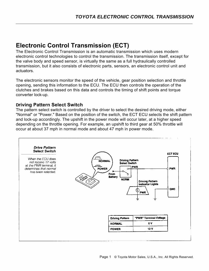
Driving Pattern Select SwitchThe pattern select switch is controlled by the driver to select the desired driving mode, either "Normal" or "Power." Based on the position of the switch, the ECT ECU selects the shift pattern and lock-up accordingly. The upshift in the power mode will occur later, at a higher speed depending on the throttle opening. For example, an upshift to third gear at 50% throttle will occur at about 37 mph in normal mode and about 47 mph in power mode.
TOYOTA ELECTRONIC CONTROL TRANSMISSION
Page 1 © Toyota Motor Sales, U.S.A., Inc. All Rights Reserved.
The ECU has a "PWR" terminal but does not have a "Normal" terminal. When "Power" is selected, 12 volts are applied to the "PWR" terminal of the ECU and the power light illuminates. When "Normal" is selected, the voltage at "PWR" is 0 volts. When the ECU senses 0 volts at the terminal, it recognizes that "Normal" has been selected.
Beginning with the 1990 MR2 and Celica and the 1991 Previa, the pattern select switch was discontinued. In the Celica and Previa systems, several shift patterns are stored in the ECU memory. Utilizing sensory inputs, the ECU selects the appropriate shift pattern and operates the shift solenoids accordingly. The MR2 and 1993 Corolla have only one shift pattern stored in the ECU memory.
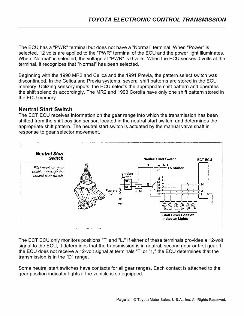
Neutral Start SwitchThe ECT ECU receives information on the gear range into which the transmission has been shifted from the shift position sensor, located in the neutral start switch, and determines the appropriate shift pattern. The neutral start switch is actuated by the manual valve shaft in response to gear selector movement.
The ECT ECU only monitors positions "T' and "L." If either of these terminals provides a 12-volt signal to the ECU, it determines that the transmission is in neutral, second gear or first gear. If the ECU does not receive a 12-volt signal at terminals "T' or "1," the ECU determines that the transmission is in the "D" range.
Some neutral start switches have contacts for all gear ranges. Each contact is attached to the gear position indicator lights if the vehicle is so equipped.
TOYOTA ELECTRONIC CONTROL TRANSMISSION
Page 2 © Toyota Motor Sales, U.S.A., Inc. All Rights Reserved.
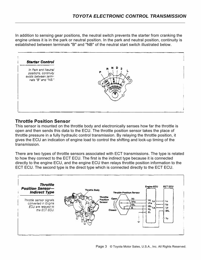
In addition to sensing gear positions, the neutral switch prevents the starter from cranking the engine unless it is in the park or neutral position. In the park and neutral position, continuity is established between terminals "B" and "NB" of the neutral start switch illustrated below.
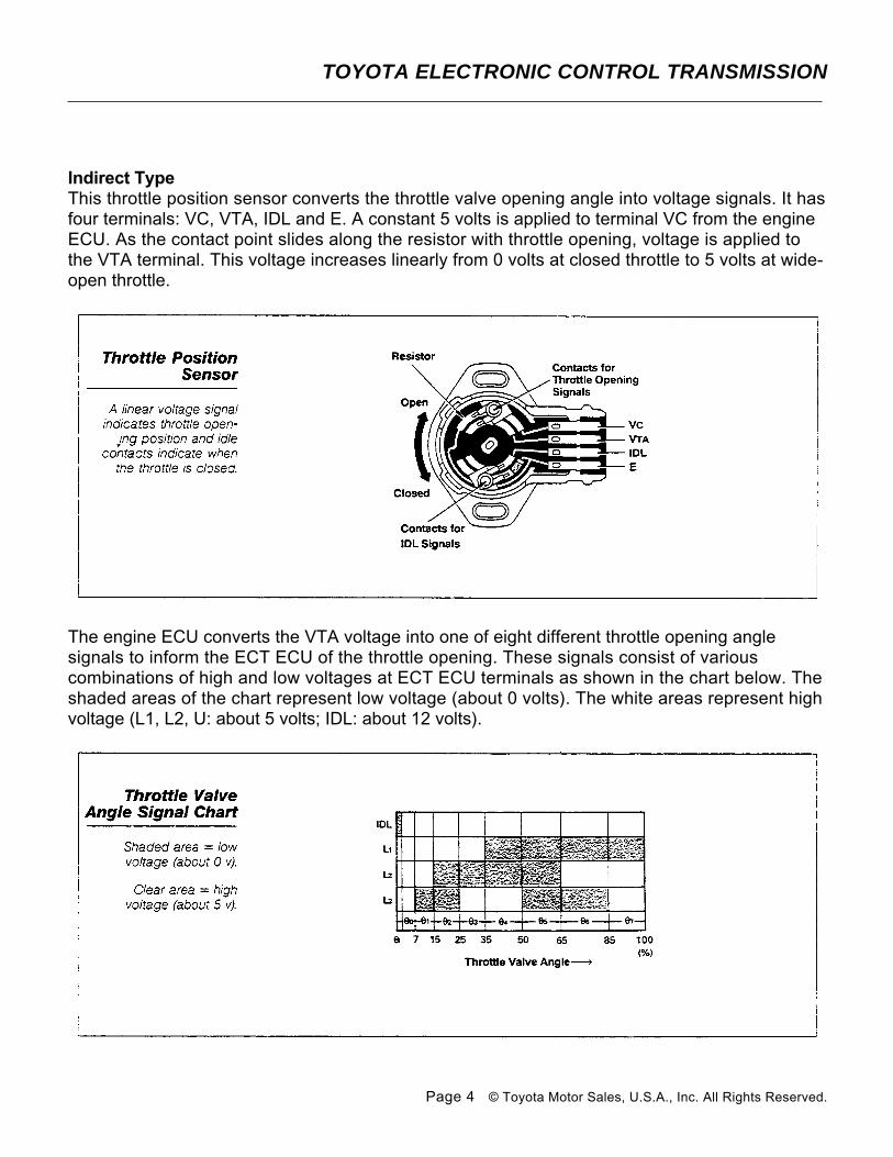
Throttle Position SensorThis sensor is mounted on the throttle body and electronically senses how far the throttle is open and then sends this data to the ECU. The throttle position sensor takes the place of throttle pressure in a fully hydraulic control transmission. By relaying the throttle position, it gives the ECU an indication of engine load to control the shifting and lock-up timing of the transmission.
There are two types of throttle sensors associated with ECT transmissions. The type is related to how they connect to the ECT ECU. The first is the indirect type because it is connected directly to the engine ECU, and the engine ECU then relays throttle position information to the ECT ECU. The second type is the direct type which is connected directly to the ECT ECU.
TOYOTA ELECTRONIC CONTROL TRANSMISSION
Page 3 © Toyota Motor Sales, U.S.A., Inc. All Rights Reserved.
Indirect TypeThis throttle position sensor converts the throttle valve opening angle into voltage signals. It has four terminals: VC, VTA, IDL and E. A constant 5 volts is applied to terminal VC from the engine ECU. As the contact point slides along the resistor with throttle opening, voltage is applied to the VTA terminal. This voltage increases linearly from 0 volts at closed throttle to 5 volts at wide-open throttle.
The engine ECU converts the VTA voltage into one of eight different throttle opening angle signals to inform the ECT ECU of the throttle opening. These signals consist of various combinations of high and low voltages at ECT ECU terminals as shown in the chart below. The shaded areas of the chart represent low voltage (about 0 volts). The white areas represent high voltage (L1, L2, U: about 5 volts; IDL: about 12 volts).
TOYOTA ELECTRONIC CONTROL TRANSMISSION
Page 4 © Toyota Motor Sales, U.S.A., Inc. All Rights Reserved.
When the throttle valve is completely closed, the contact points for the IDL signal connect the IDL and E terminals, sending an IDL signal to the ECT ECU to inform it that the throttle is fully closed.
As the ECT ECU receives the L1, L2 and D signals, it provides an output voltage from 1 to 8 volts at the TT or ECT terminal of the diagnostic check connector. The voltage signal varies depending on the throttle opening angle and informs the technician whether or not the throttle opening signal is being input properly.
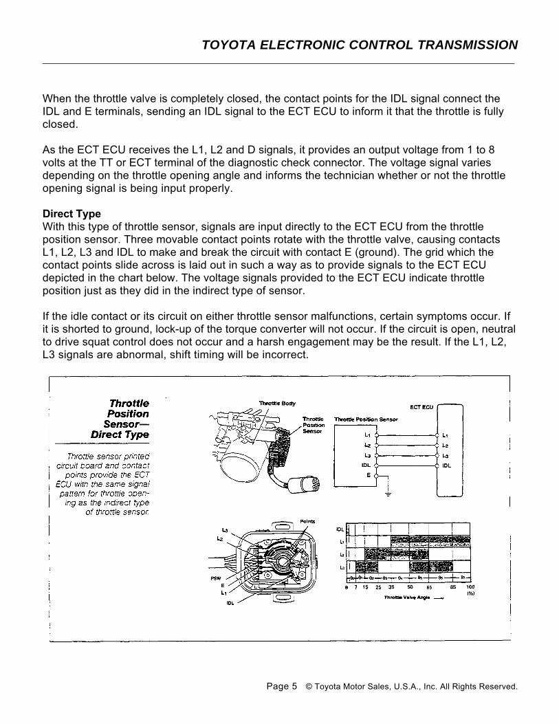
Direct TypeWith this type of throttle sensor, signals are input directly to the ECT ECU from the throttle position sensor. Three movable contact points rotate with the throttle valve, causing contacts L1, L2, L3 and IDL to make and break the circuit with contact E (ground). The grid which the contact points slide across is laid out in such a way as to provide signals to the ECT ECU depicted in the chart below. The voltage signals provided to the ECT ECU indicate throttle position just as they did in the indirect type of sensor.
If the idle contact or its circuit on either throttle sensor malfunctions, certain symptoms occur. If it is shorted to ground, lock-up of the torque converter will not occur. If the circuit is open, neutral to drive squat control does not occur and a harsh engagement may be the result. If the L1, L2, L3 signals are abnormal, shift timing will be incorrect.
TOYOTA ELECTRONIC CONTROL TRANSMISSION
Page 5 © Toyota Motor Sales, U.S.A., Inc. All Rights Reserved.

Water Temperature SensorThe water temperature sensor monitors engine coolant temperature and is typically located near the cylinder head water outlet. A thermistor is mounted within the temperature sensor, and its resistance value decreases as the temperature increases. Therefore, when the engine temperature is low, resistance will be high.
When the engine coolant is below a predetermined temperature, the engine performance and the vehicle's drivability would suffer if the transmission were shifted into overdrive or the converter clutch were locked-up. The engine ECU monitors coolant temperature and sends a signal to terminal OD1 of the ECT ECU. The ECU prevents the transmission from upshifting into overdrive and lock-up until the coolant has reached a predetermined temperature. This temperature will vary from 122'F to 162’F depending on the transmission and vehicle model. For specific temperatures, refer to the ECT Diagnostic Information chart in the appendix of this book.
Some models, depending on the model year, cancel upshifts to third gear at lower temperatures. This information is found in the appendix and is indicated in the heading of the OD Cancel Temp column of the ECT Diagnostic Information chart by listing in parenthesis the temperature for restricting third gear.
TOYOTA ELECTRONIC CONTROL TRANSMISSION
Page 6 © Toyota Motor Sales, U.S.A., Inc. All Rights Reserved.
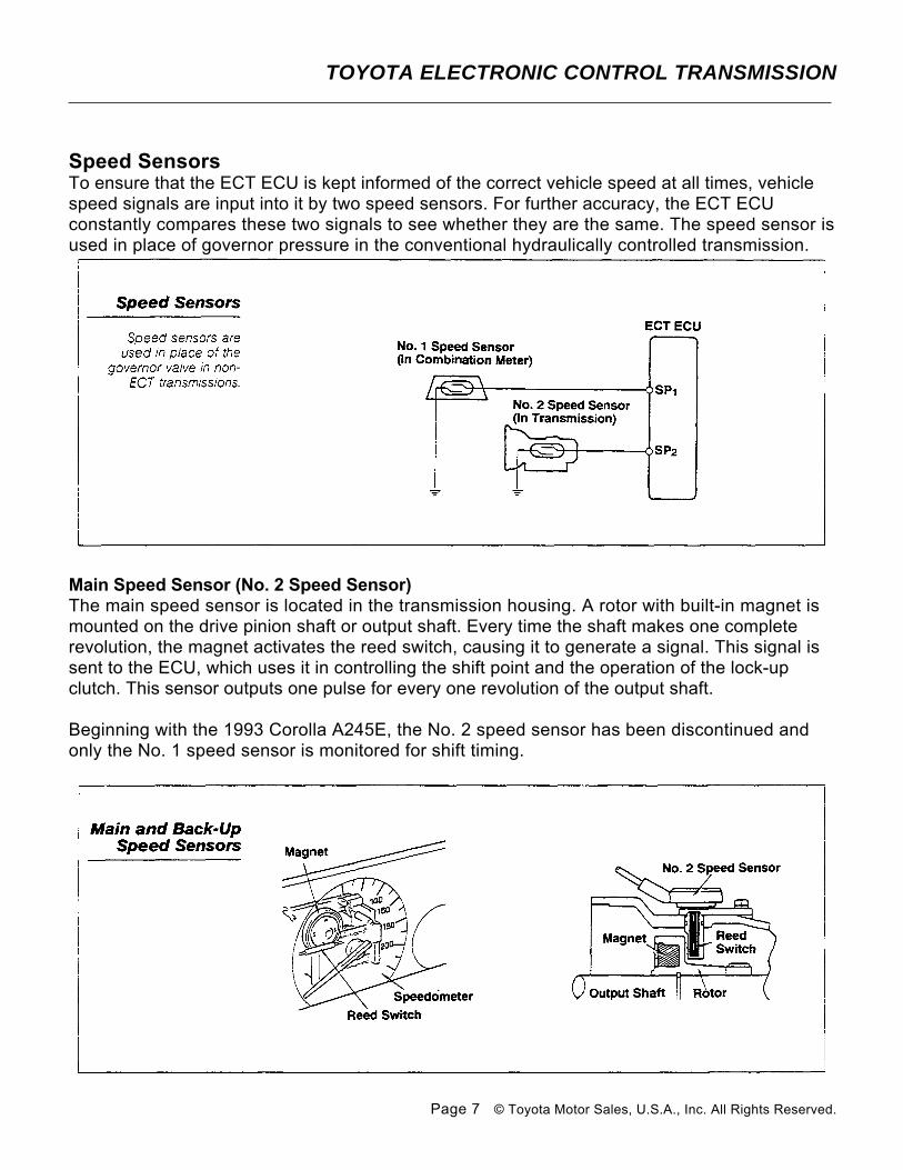
Speed SensorsTo ensure that the ECT ECU is kept informed of the correct vehicle speed at all times, vehicle speed signals are input into it by two speed sensors. For further accuracy, the ECT ECU constantly compares these two signals to see whether they are the same. The speed sensor is used in place of governor pressure in the conventional hydraulically controlled transmission.
Main Speed Sensor (No. 2 Speed Sensor)The main speed sensor is located in the transmission housing. A rotor with built-in magnet is mounted on the drive pinion shaft or output shaft. Every time the shaft makes one complete revolution, the magnet activates the reed switch, causing it to generate a signal. This signal is sent to the ECU, which uses it in controlling the shift point and the operation of the lock-up clutch. This sensor outputs one pulse for every one revolution of the output shaft.
Beginning with the 1993 Corolla A245E, the No. 2 speed sensor has been discontinued and only the No. 1 speed sensor is monitored for shift timing.
TOYOTA ELECTRONIC CONTROL TRANSMISSION
Page 7 © Toyota Motor Sales, U.S.A., Inc. All Rights Reserved.
Back- Up Speed Sensor (No.1 Speed Sensor)The back-up speed sensor is built into the combination meter assembly and is operated by the speedometer cable. The sensor consists of an electrical reed switch and a multiple pole permanent magnet assembly. As the speedometer cable turns, the permanent magnet rotates past the reed switch. The magnetic flux lines between the poles of the magnet cause the contacts to open and close as they pass. The sensor outputs four pulses for every one revolution of the speedometer cable.
The sensor can also be a photocoupler type which uses a photo transistor and light-emitting diode (LED). The LED is aimed at the phototransistor and separated by a slotted wheel. The slotted wheel is driven by the speedometer cable. As the slotted wheel rotates between the LED and photo diode, it generates 20 light pulses for each rotation. This signal is converted within the phototransistor to four pulses sent to the ECU.
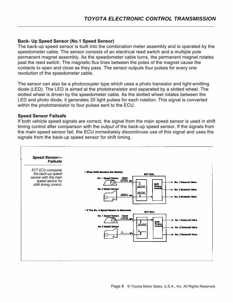
Speed Sensor FailsafeIf both vehicle speed signals are correct, the signal from the main speed sensor is used in shift timing control after comparison with the output of the back-up speed sensor. If the signals from the main speed sensor fail, the ECU immediately discontinues use of this signal and uses the signals from the back-up speed sensor for shift timing.
TOYOTA ELECTRONIC CONTROL TRANSMISSION
Page 8 © Toyota Motor Sales, U.S.A., Inc. All Rights Reserved.
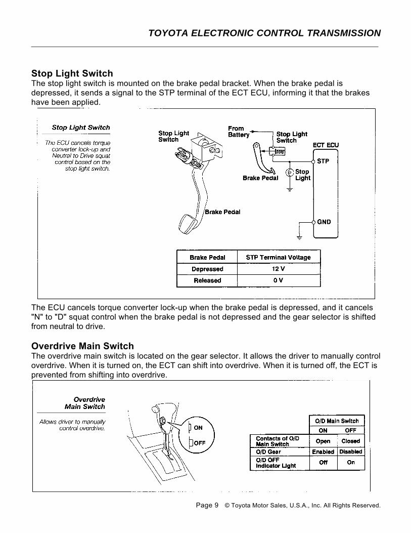
Stop Light SwitchThe stop light switch is mounted on the brake pedal bracket. When the brake pedal is depressed, it sends a signal to the STP terminal of the ECT ECU, informing it that the brakes have been applied.
The ECU cancels torque converter lock-up when the brake pedal is depressed, and it cancels "N" to "D" squat control when the brake pedal is not depressed and the gear selector is shifted from neutral to drive.
Overdrive Main SwitchThe overdrive main switch is located on the gear selector. It allows the driver to manually control overdrive. When it is turned on, the ECT can shift into overdrive. When it is turned off, the ECT is prevented from shifting into overdrive.
TOYOTA ELECTRONIC CONTROL TRANSMISSION
Page 9 © Toyota Motor Sales, U.S.A., Inc. All Rights Reserved.
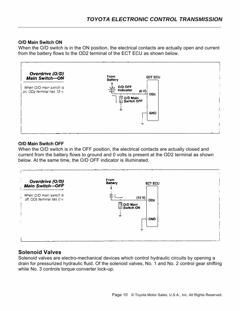
O/D Main Switch ONWhen the O/D switch is in the ON position, the electrical contacts are actually open and current from the battery flows to the OD2 terminal of the ECT ECU as shown below.
O/D Main Switch OFFWhen the O/D switch is in the OFF position, the electrical contacts are actually closed and current from the battery flows to ground and 0 volts is present at the OD2 terminal as shown below. At the same time, the O/D OFF indicator is illuminated.
Solenoid ValvesSolenoid valves are electro-mechanical devices which control hydraulic circuits by opening a drain for pressurized hydraulic fluid. Of the solenoid valves, No. 1 and No. 2 control gear shifting while No. 3 controls torque converter lock-up.
TOYOTA ELECTRONIC CONTROL TRANSMISSION
Page 10 © Toyota Motor Sales, U.S.A., Inc. All Rights Reserved.
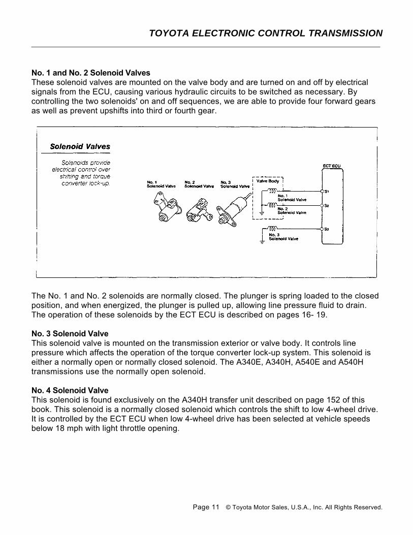
No. 1 and No. 2 Solenoid Valves These solenoid valves are mounted on the valve body and are turned on and off by electrical signals from the ECU, causing various hydraulic circuits to be switched as necessary. By controlling the two solenoids' on and off sequences, we are able to provide four forward gears as well as prevent upshifts into third or fourth gear.
The No. 1 and No. 2 solenoids are normally closed. The plunger is spring loaded to the closed position, and when energized, the plunger is pulled up, allowing line pressure fluid to drain. The operation of these solenoids by the ECT ECU is described on pages 16- 19.
No. 3 Solenoid ValveThis solenoid valve is mounted on the transmission exterior or valve body. It controls line pressure which affects the operation of the torque converter lock-up system. This solenoid is either a normally open or normally closed solenoid. The A340E, A340H, A540E and A540H transmissions use the normally open solenoid.
No. 4 Solenoid ValveThis solenoid is found exclusively on the A340H transfer unit described on page 152 of this book. This solenoid is a normally closed solenoid which controls the shift to low 4-wheel drive. It is controlled by the ECT ECU when low 4-wheel drive has been selected at vehicle speeds below 18 mph with light throttle opening.
TOYOTA ELECTRONIC CONTROL TRANSMISSION
Page 11 © Toyota Motor Sales, U.S.A., Inc. All Rights Reserved.
Functions of ECT ECU
Control of Shift Timing
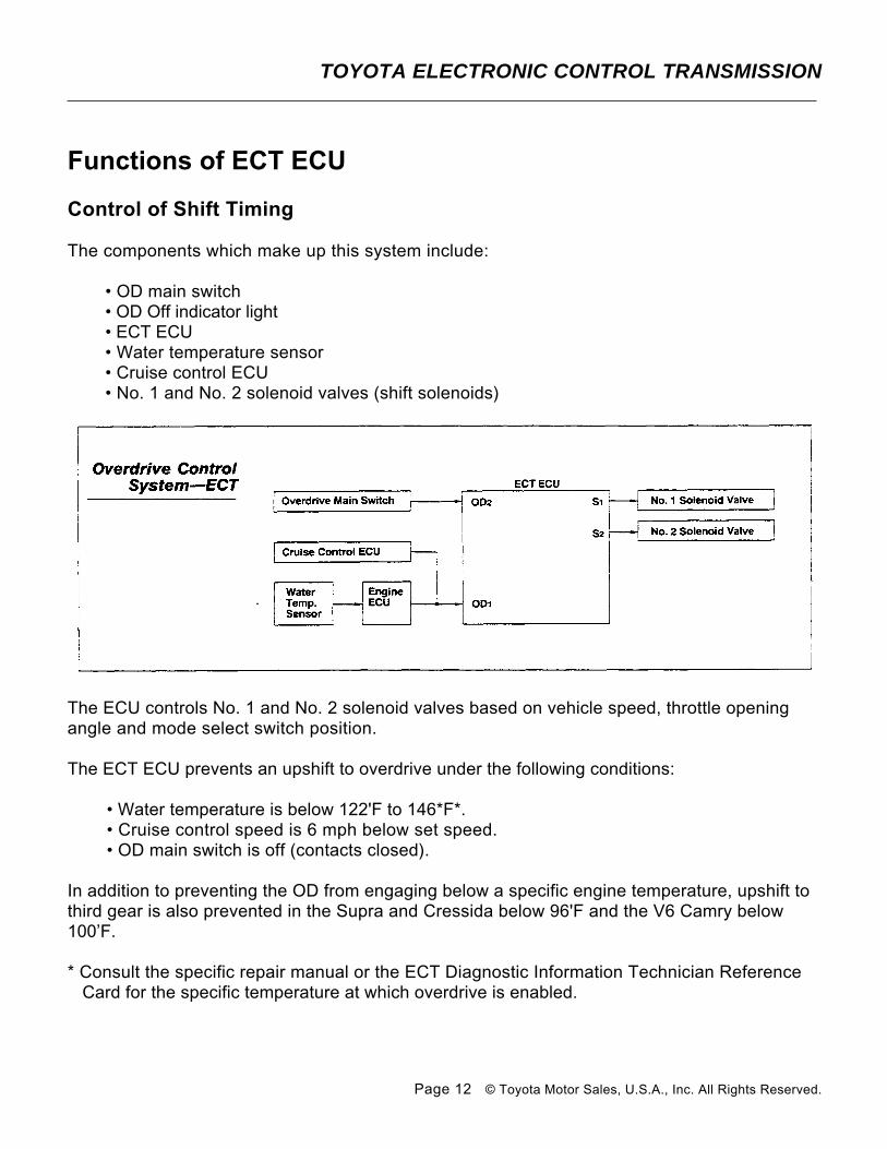
The components which make up this system include:
• OD main switch • OD Off indicator light • ECT ECU • Water temperature sensor • Cruise control ECU • No. 1 and No. 2 solenoid valves (shift solenoids)
The ECU controls No. 1 and No. 2 solenoid valves based on vehicle speed, throttle opening angle and mode select switch position.
The ECT ECU prevents an upshift to overdrive under the following conditions:
• Water temperature is below 122'F to 146*F*. • Cruise control speed is 6 mph below set speed. • OD main switch is off (contacts closed).
In addition to preventing the OD from engaging below a specific engine temperature, upshift to third gear is also prevented in the Supra and Cressida below 96'F and the V6 Camry below 100’F.
* Consult the specific repair manual or the ECT Diagnostic Information Technician Reference Card for the specific temperature at which overdrive is enabled.
TOYOTA ELECTRONIC CONTROL TRANSMISSION
Page 12 © Toyota Motor Sales, U.S.A., Inc. All Rights Reserved.
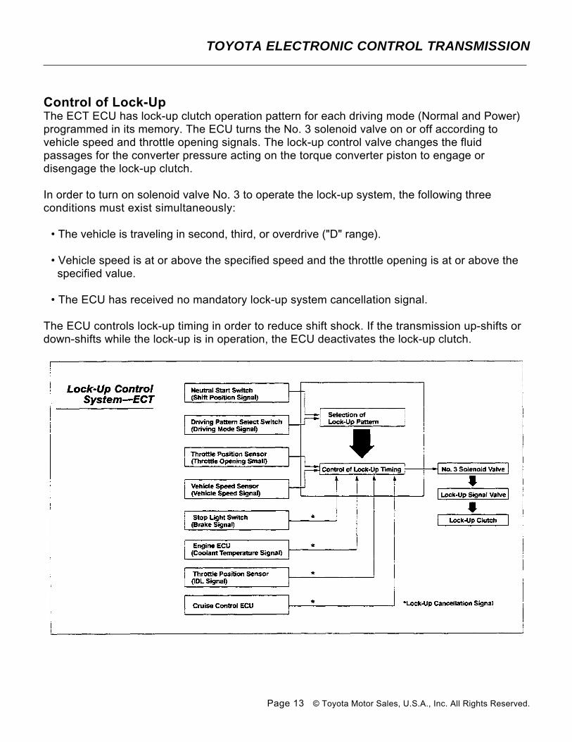
Control of Lock-UpThe ECT ECU has lock-up clutch operation pattern for each driving mode (Normal and Power) programmed in its memory. The ECU turns the No. 3 solenoid valve on or off according to vehicle speed and throttle opening signals. The lock-up control valve changes the fluid passages for the converter pressure acting on the torque converter piston to engage or disengage the lock-up clutch.
In order to turn on solenoid valve No. 3 to operate the lock-up system, the following three conditions must exist simultaneously:
• The vehicle is traveling in second, third, or overdrive ("D" range).
• Vehicle speed is at or above the specified speed and the throttle opening is at or above the specified value.
• The ECU has received no mandatory lock-up system cancellation signal.
The ECU controls lock-up timing in order to reduce shift shock. If the transmission up-shifts or down-shifts while the lock-up is in operation, the ECU deactivates the lock-up clutch.
TOYOTA ELECTRONIC CONTROL TRANSMISSION
Page 13 © Toyota Motor Sales, U.S.A., Inc. All Rights Reserved.
The ECU will cancel lock-up if any of the following conditions occur:
• The stop light switch comes on.
• The coolant temperature is below 122'F to 145’F depending on the model. Consult the vehicle repair manual or the ECT Diagnostic Information Technician Reference Card.
• The IDL contact points of the throttle position sensor close.
• The vehicle speed drops about 6 mph or more below the set speed while the cruise control system is operating.
The stop light switch and IDL contacts are monitored in order to prevent the engine from stalling in the event that the rear wheels lock up during braking. Coolant temperature is monitored to enhance drivability and transmission warm-up. The cruise control monitoring allows the engine to run at higher rpm and gain torque multiplication through the torque converter.
Neutral to Drive Squat ControlWhen the transmission is shifted from the neutral to the drive range, the ECU prevents it from shifting directly into first gear by causing it to shift into second or third gear before it shifts to first gear. It does this in order to reduce shift shock and squatting of the vehicle.
Engine Torque ControlTo prevent shifting shock on some models, the ignition timing is retarded temporarily during gear shifting in order to reduce the engine's torque. The TCCS and ECT ECU monitors engine speed signals (Ne) and transmission output shaft speed (No. 2 speed sensor) then determines how much to retard the ignition timing based on shift pattern selection and throttle opening angle.
TOYOTA ELECTRONIC CONTROL TRANSMISSION
Page 14 © Toyota Motor Sales, U.S.A., Inc. All Rights Reserved.
Fail-Safe OperationThe ECT ECU has several fail-safe functions to allow the vehicle to continue operating even if a malfunction occurs in the electrical system during driving. The speed sensor fail-safe has already been discussed on page 8.
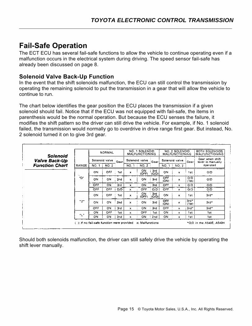
Solenoid Valve Back-Up FunctionIn the event that the shift solenoids malfunction, the ECU can still control the transmission by operating the remaining solenoid to put the transmission in a gear that will allow the vehicle to continue to run.
The chart below identifies the gear position the ECU places the transmission if a given solenoid should fail. Notice that if the ECU was not equipped with fail-safe, the items in parenthesis would be the normal operation. But because the ECU senses the failure, it modifies the shift pattern so the driver can still drive the vehicle. For example, if No. 1 solenoid failed, the transmission would normally go to overdrive in drive range first gear. But instead, No. 2 solenoid turned it on to give 3rd gear.
Should both solenoids malfunction, the driver can still safely drive the vehicle by operating the shift lever manually.
TOYOTA ELECTRONIC CONTROL TRANSMISSION
Page 15 © Toyota Motor Sales, U.S.A., Inc. All Rights Reserved.

ECT Shift Valve OperationTwo electrically operated solenoids control the shifting of all forward gears in the Toyota electronic control four speed automatic transmission. These solenoids are controlled by an ECU which uses throttle position and speed sensor input to determine when the solenoids are turned on. The solenoids normal position is closed, but when it is turned on, it opens to drain fluid from the hydraulic circuit. Solenoid No. 1 controls the 2-3 shift valve. It is located between the manual valve and the top of the 2-3 shift valve. Solenoid No. 2 controls the 1-2 shift valve and the 3-4 shift valve.
First GearDuring first gear operation, solenoid No. 1 is on and solenoid No. 2 is off. With line pressure drained from the top of the 2-3 shift valve by solenoid No. 1, spring tension at the base of the valve pushes it upward. With the shift valve up, line pressure flows from the manual valve through the 2-3 shift valve and on to the base of the 3-4 shift valve.
With solenoid No. 2 off, line pressure pushes the 1-2 shift valve down. In this position, the 1-2 shift valve blocks line pressure from the manual valve. Line pressure and spring tension at the base of the 3-4 shift valve push it upward.
TOYOTA ELECTRONIC CONTROL TRANSMISSION
Page 16 © Toyota Motor Sales, U.S.A., Inc. All Rights Reserved.
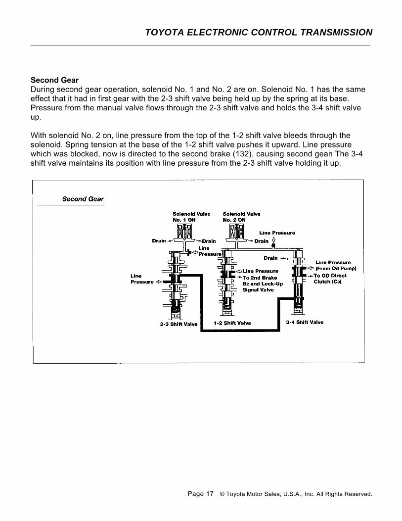
Second GearDuring second gear operation, solenoid No. 1 and No. 2 are on. Solenoid No. 1 has the same effect that it had in first gear with the 2-3 shift valve being held up by the spring at its base. Pressure from the manual valve flows through the 2-3 shift valve and holds the 3-4 shift valve up.
With solenoid No. 2 on, line pressure from the top of the 1-2 shift valve bleeds through the solenoid. Spring tension at the base of the 1-2 shift valve pushes it upward. Line pressure which was blocked, now is directed to the second brake (132), causing second gean The 3-4 shift valve maintains its position with line pressure from the 2-3 shift valve holding it up.
TOYOTA ELECTRONIC CONTROL TRANSMISSION
Page 17 © Toyota Motor Sales, U.S.A., Inc. All Rights Reserved.
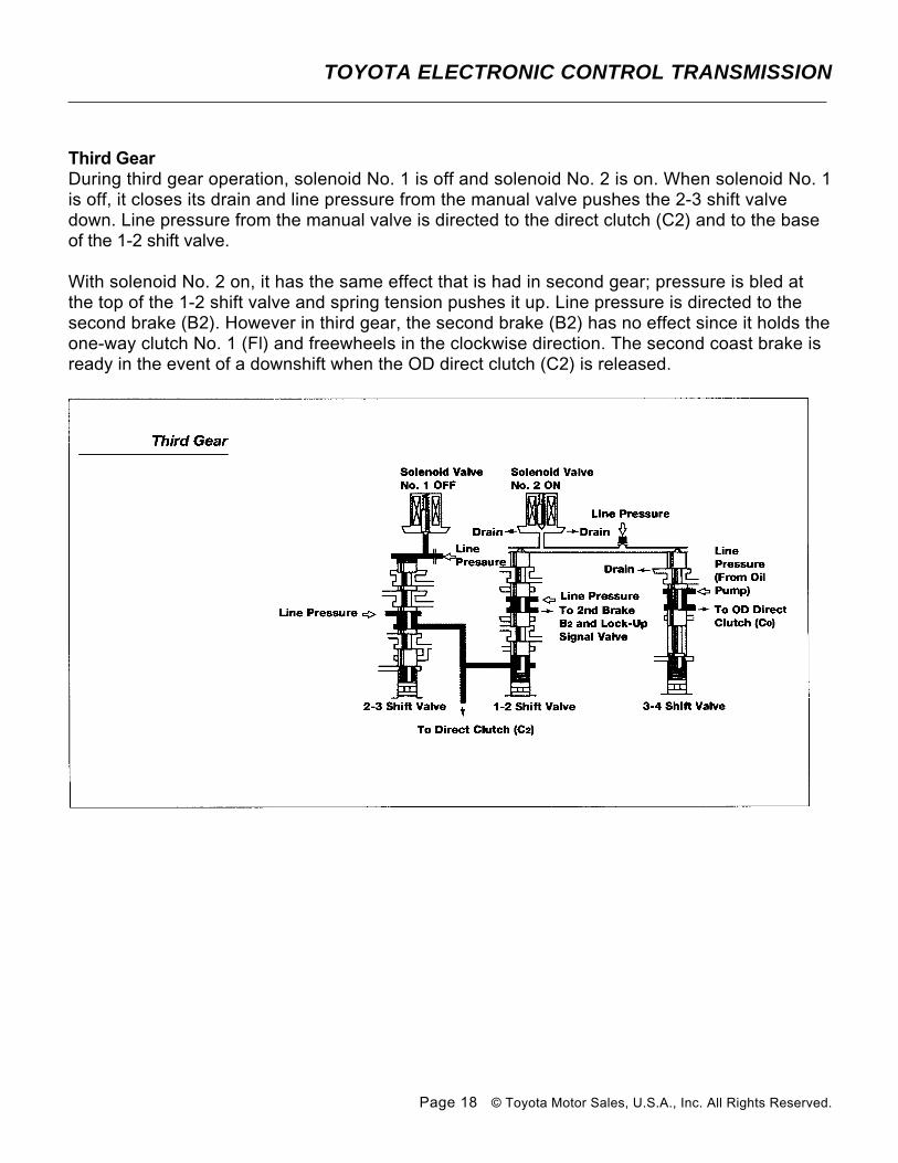
Third GearDuring third gear operation, solenoid No. 1 is off and solenoid No. 2 is on. When solenoid No. 1 is off, it closes its drain and line pressure from the manual valve pushes the 2-3 shift valve down. Line pressure from the manual valve is directed to the direct clutch (C2) and to the base of the 1-2 shift valve.
With solenoid No. 2 on, it has the same effect that is had in second gear; pressure is bled at the top of the 1-2 shift valve and spring tension pushes it up. Line pressure is directed to the second brake (B2). However in third gear, the second brake (B2) has no effect since it holds the one-way clutch No. 1 (Fl) and freewheels in the clockwise direction. The second coast brake is ready in the event of a downshift when the OD direct clutch (C2) is released.
TOYOTA ELECTRONIC CONTROL TRANSMISSION
Page 18 © Toyota Motor Sales, U.S.A., Inc. All Rights Reserved.

Fourth GearDuring fourth gear operation, both solenoids are off. When solenoid No. 1 is off, its operation is the same as in second and third gears.
A third solenoid controls lock-up operation.
Reprinted with permission by Toyota Motor Sales, USA, Inc.,from the Automatic Transmission Course #262 textbook.
TOYOTA ELECTRONIC CONTROL TRANSMISSION
Page 19 © Toyota Motor Sales, U.S.A., Inc. All Rights Reserved.