automotive transmission explained and compared to the ... · 3 | page autotransexplainedver1.docx 1...
TRANSCRIPT

1 | Page AutoTransExplainedVer1.docx
Automotive transmission explained
and compared to the RADIALcvt
Dr. J. J. Naude 18 December 2017
Version 1.

2 | Page AutoTransExplainedVer1.docx
Table of contents
1 Automotive transmissions state of the art 3
2 MT (manual transmission) 3
3 AMT (Automated manual transmission) 4
4 DCT (Dual clutch transmission) 6
5 AT (Automatic transmission) 7
6 CVT (Continuously variable transmission) 8
6.1 Belt and Chain CVT 9
6.2 Toroidal CVT 10
7 Stepped vs infinitely variable transmissions 11
8 In summary 13
9 What is different in the RADIALcvt 15
List of Figures
Figure 4 ZF 6 speed manual transmission together with a manual transmission schematic. ... 4
Figure 5 BMW SMG AMT ........................................................................................................... 5
Figure 6 ZF's 7 speed DCT .......................................................................................................... 6
Figure 7 Merceded 9 speed 9G-Tronic AT. ................................................................................ 8
Figure 8 Subaru Linear Tronic CVT ............................................................................................. 9
Figure 9 Bosch steel belt CVT. .................................................................................................... 9
Figure 10 Nissan Extroid toroidal CVT ..................................................................................... 10
Figure 11 Transmission fuel economy advances since 2007. .................................................. 12
Figure 12 Automotive transmission volumes presented by Jatco. .......................................... 12

3 | Page AutoTransExplainedVer1.docx
1 Automotive transmissions state of the art
The automotive transmission is a device that is located between the engine and wheels and
is used to alter the ratio between the engine and wheels to allow the vehicle to operate
optimally at different speeds and loads. In recent years a much bigger emphasis is being
placed on the automotive transmission as an optimization and coordination tool between
the power source (engine and/or electric motor) and the vehicle varying load demands to
produce lower fuel consumption and emissions. This is particular important in the cased of
hybrid vehicles where an additional power storing component (batteries) are included to
harness energy previously being wasted, for example in braking. Above exponentially
increased the complexity of optimization of the vehicle powertrain as a whole.
Automotive transmissions can be categorised in the following categories
MT Manual transmission
AMT Automated manual transmission
DCT Dual clutch transmission
AT Automatic transmission (traditional automatic transmission)
CVT Continuously variable transmission
2 MT (manual transmission)
MT is the simplest transmission, requiring the highest level of driver input, with the highest
mechanical efficiency and comes in at the lowest cost.
All transmission require a launching or pull away device, the simplest and cheapest of which
is a dry clutch. A MT employs a driver operated dry clutch at the input from the engine.
Meshing gear sets with different ratios are selectively engaged by the driver according to
the drivers driving style.
MT’s typically have up to six ratios, because more would be ineffectively used by the driver.
MT is further classified as the simplest stepped ratio transmission, since it is characterised
by discrete stepped ratio’s

4 | Page AutoTransExplainedVer1.docx
Figure 1 ZF 6 speed manual transmission together with a manual transmission schematic.
The ZF 6 speed manual transmission is presented in the left of Figure 1 and to the right a
schematic of a typical MT to the right.
Mechanical efficiency: The manual transmission typically only involves power transmission
through 2 meshing gear sets without any hydraulic control and therefore presents the
automotive transmission with the highest mechanical efficiency, typically above 95%.
Fuel consumption and emissions: The fuel consumption and emissions of a MT transmission
is directly related to the driving style of the driver.
Power interruption: During gear shifting a power interruption between the engine and
wheels occur. Power interruptions are typically associated with jerks as well as fuel
consumption and emission spikes.
3 AMT (Automated manual transmission)
An AMT is a manual transmission in which the clutch and gear shifting has been automated.
This automation can be hydraulic or electric or a combination. Dry or wet (clutch operates in
oil ) clutches are used.
AMT’s presents the cheapest and simplest form of an automated/automatic transmission
but has largely fall out of favour due to its shifting quality as a result of power interruptions
during shifting..
5 | Page AutoTransExplainedVer1.docx
Mechanical efficiency: Losses in AMT are the same as for the MT but additionally include
the power consumption losses of the automated clutch and ratio shifting system.
The mechanical efficiency of an AMT is therefore a little bit lower than the MT because of
the power consumed by the automated system.
Fuel consumption and emissions: As a AMT is an automated or 2 pedal transmission, the
ratio selection is done automatically and therefore the AMT fuel consumption and emissions
is less dependent on the driver’s driving style.
Power interruption: During gear shifting a power interruption between the engine and
wheels occur. Power interruptions are typically associated with jerks as well as fuel
consumption and emission spikes.
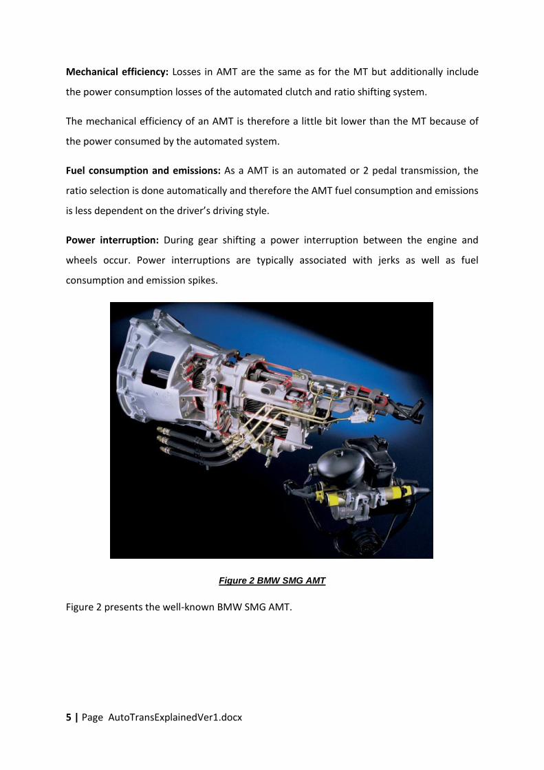
Figure 2 BMW SMG AMT
Figure 2 presents the well-known BMW SMG AMT.

6 | Page AutoTransExplainedVer1.docx
4 DCT (Dual clutch transmission)
A DCT is a transmission which basically integrates two AMT’s and therefore also has two
automated clutches that can be wet or dry. For example the first AMT will include gears 1, 3,
5 and 7 and the second 2, 4 and 6 in a 7 speed DCT. The rationale behind the DCT is that if
the first AMT is in a certain engaged gear with its clutch engaged, the ratio control algorithm
will determine to which most likely gear of the second AMT (with its clutch not engaged) the
next gear shift will be, and that gear will be selected by the control system.
When gearshift from the first AMT to second AMT is required the process is simply the
disengagement of the first AMT clutch and the engagement of the second AMT clutch,
which can be done very fast.
Figure 3 ZF's 7 speed DCT
DCT’s therefore have very fast ratio shifting, but are more costly and heavy that AMT’s
because of the additional components. The disengaging and engaging clutch can also
overlap to produce an uninterrupted power transmission between the engine and wheels.
Figure 3 presents ZF’s 7 speed DCT.

7 | Page AutoTransExplainedVer1.docx
Mechanical efficiency: Losses in DCT’s are similar as for the AMT and therefore has a similar
mechanical efficiency.
Fuel consumption and emissions: As a DCT is an automated or 2 pedal transmission, the
ratio selection is done automatically and therefore the DCT fuel consumption and emissions
is less dependent on the driver’s driving style.
Power interruption: During gear shifting no power interruption between the engine and
wheels occur.
5 AT (Automatic transmission)
Automatic transmission function very differently from MT’s, AMT’s and DCT’s and utilize
planetary gear sets in combination with wet clutch packs to realise the gear ratios. For a
launching device automatic transmission use a torque convertor. A torque convertor is a
hydraulic device that under idle engine speeds transmit a very low amount of torque (allow
the vehicle to creep) while the torque being transmitted increases at the engine speed
increase. Torque convertors are not very efficient devices and are only used for pull away
and some gear shifts while the rest of the time they employ a lockup device. Figure 4
presents the Mercedes 9 speed automatic where the nine speeds are generated by
engaging combinations of the 6 clutch packs (shifting elements) engaging 4 planetary gear
sets. To operate AT’s required a hydraulic control system for actuating the various clutch
packs. AT’s are therefore also classified as stepped transmissions the same as MT’s, AMT’s
and DCT’s. Note that any transmission in which ratio selection is automated are often
referred to as “automatic transmissions” or “two pedal transmissions” and is often mistaken
for AT’s. AT’s as per above, specifically refer to an automated transmission in which gear
ratios are realised via planetary gear systems.
Mechanical efficiency: Losses in AT’s are generally more than in DCT’s as a result of the drag
losses in unengaged clutches as well as the hydraulic control system that needs to maintain
pressure even when no gear change is taking place, which results in a lower mechanical
efficiency

8 | Page AutoTransExplainedVer1.docx
Figure 4 Merceded 9 speed 9G-Tronic AT.
Fuel consumption and emissions: As a AT is an automated or 2 pedal transmission, the ratio
selection is done automatically and therefore the AT fuel consumption and emissions is less
dependent on the driver’s driving style.
Power interruption: During gear shifting no power interruption between the engine and
wheels occur as the disengaging and engaging clutches overlap.
6 CVT (Continuously variable transmission)
CVT presents the only non-stepped transmission in that its ratio can be continuously varied
in infinite small steps throughout its ratio range. CVT’s also require a launching or pull away
device which can be a wet clutch or torque convertor. All current CVT in production or
development employs a friction drive. This friction drive involves steel on steel contact,
lubricated in a traction fluid. The traction fluid has a special property in that it momentarily
solidifies under high contact pressure (1 to 4 GPa) in the steel on steel contact and thus
provides the friction drive as well as provide a solid boundary layer separating the steel on
9 | Page AutoTransExplainedVer1.docx
steel contact. Currently only the Belt and Chain types of CVT’s are currently in production
while the Toroidal, Cone ring, Planet ball and Radial driver CVT’s are in development.
6.1 Belt and Chain CVT
The belt/chain and pulley CVT employs two sets of split pulleys and a metal belt or chain.
The pulleys are hydraulically clamped together to tension the belt/chain resulting in a
friction drive in traction fluid (special oil) between the belt/chain sides and the pulleys.
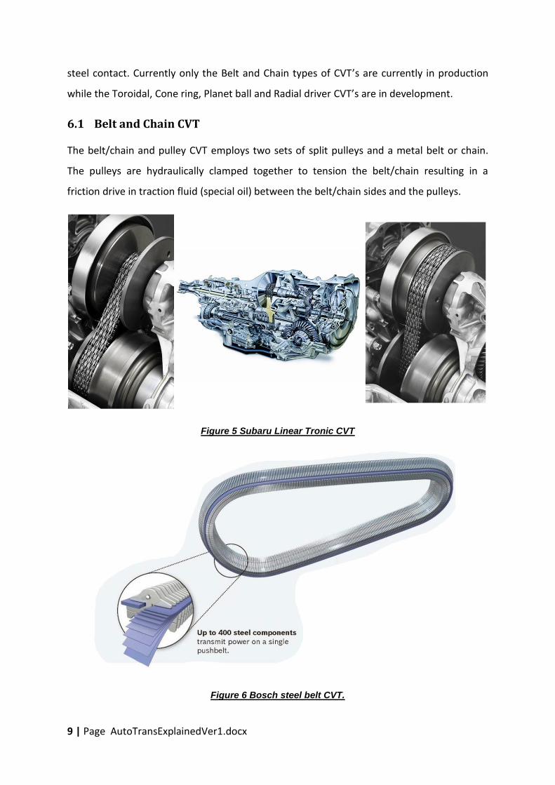
Figure 5 Subaru Linear Tronic CVT
Figure 6 Bosch steel belt CVT.

10 | Page AutoTransExplainedVer1.docx
The ratio is established by the varying radius on the input and output pulley. Figure 5
presents the Subaru Linear Tronic CVT with the image on the left in low ratio and on the
right in high ratio.
Above Subaru Linear Tronic uses the chain manufactured by LUK while Figure 6 presents the
steel belt manufactured by Bosch.
6.2 Toroidal CVT
Figure 7 Nissan Extroid toroidal CVT

11 | Page AutoTransExplainedVer1.docx
A second type of CVT is the toroidal CVT which utilises rollers running on different radiuses
between two toroidal shaped input and output. Nissan had such a transmission in
production called the Xtroid up to 2010 and is presented in Figure 7.
Mechanical efficiency: The losses in current CVT are the highest of all automated
transmissions because of the losses in the friction drive interface and the hydraulic control
system. Current commercial CVT’s have a mechanical average efficiency of about 85%.
Fuel consumption and emissions: As a CVT is an automated or 2 pedal transmission, the
ratio selection is done automatically and therefore the CVT fuel consumption and emissions
is less dependent on the driver’s driving style.
Power interruption: CVT’s shift seamlessly without any power interruption or the actuation
of any clutches and therefore provides the highest level of ratio shifting.
7 Stepped vs infinitely variable transmissions
As the automotive transmission is the coupling device between the engine and wheels of
the vehicle, it purpose is to match the capabilities of the engine (engine torque and speed)
to the wheel requirements (speed and torque) while operating the engine at its most
efficient point in terms of fuel consumption. Stepped transmission can perform this
optimization in a “stepped” manner while CVT’s can perform this optimization to the
highest level. However CVT’s have the lowest mechanical efficiency of all automotive
transmissions, but provides the highest level of non-stepped ratio shifting producing the
highest level of engine optimization as far as fuel consumption and emissions are
concerned.
Above results in a race between CVT manufacturers to continually increase the mechanical
efficiency of the CVT vs automated stepped ratio transmission manufacturers to continually
add stepped ratios to increase the engine optimization levels. This is being done within the
limits of cost, packaging.
Figure 8 presents a presentation by Bosch showing the advances (mainly by improving the
mechanical efficiency and ratio range) of the CVT in terms of fuel consumption since 2007.
The fuel consumption of the manual transmission is taken as a reference and between 2007

12 | Page AutoTransExplainedVer1.docx
and 2017 great advances have especially been made by CVT’s, DCT’s and high ratio AT’s to
improve fuel consumption improvements up to almost 10% above manual transmissions.
Figure 8 Transmission fuel economy advances since 2007.
Figure 9 Automotive transmission volumes presented by Jatco.

13 | Page AutoTransExplainedVer1.docx
Figure 9 presents the historic automotive transmission production volumes since 1970 up to
2017 and forecasted up to 2020, which shown the market share gain by CVT and DCT at the
expense of AT’s and MT’s.
8 In summary
The advantage that sets the CVT apart from all other transmission is its ability to change its
ratio continuously in infinite small increments and is called CVT capability. This feature is
used to optimise the engine for all load conditions to always run the engine at its most
efficient point in terms of fuel consumption and/or emissions. In cases where the driver
demands maximum acceleration the engine is operated at maximum power point while the
ratio adjusts as the vehicle accelerates.
However the disadvantage that sets the CVT apart from all other transmission is the fact
that it is a friction drive where the friction drive has a much lower mechanical efficiency
than a gear set in the case of MT, AMT, DCT or a planetary gear set in the case of AT.
In the race for the best fuel efficiency and emissions the following are the mayor trade-offs:
CVT have full CVT capability but a lower mechanical efficiency, thus its full CVT
capability is used to compensate for the lower mechanical efficiency and therefore
all development efforts are aimed at increasing the transmission mechanical
efficiency and ratio range.
All other stepped transmissions have partial CVT capability but higher mechanical
efficiency, where in this case development is focused on increasing the ratios
(currently up to 10) to increase partial CVT capability while reducing the shifting
losses between ratio shifts.
Above is then further dependent on the specific vehicle class which also introduce cost
limitations.
The current state of affairs in above race is that AT and DCT are now at 10 ratios with a ratio
spread of 10. Ratio spread is simply the highest ratio divided by the lowers ratio.
Current CVT cannot generate a ratio spread of 10 in one belt/chain and pulley or toroidal
system and therefore need to be integrated in a at least two mode gear system to increase

14 | Page AutoTransExplainedVer1.docx
the ratio spread to 10. Such a two mode system is typically synchronous, thus the overall
ratio remains constant during the mode change.
To complicate matters even further is the fact that different transmission mechanical
efficiencies do not react the same under different load and speeds and therefore introduce
a further control requirement as follows:
For CVT the clamping for is controlled very precisely, because over clamping causes
lower mechanical efficiency while under clamping will cause damage to the
transmission. With lower overall clamping a smaller hydraulic control pump can be
used which brings down the hydraulic losses.
For stepped transmissions the ratio selection and control is critical as well as the
shifting between gears without a torque interruption. This typically involves the
controlled disengagement of the clutch associated with the current gear to overlap
with the engagement of the clutch associated with the next gear.
In all of above whenever complexity is increased the cost also increases and thus a balance
between performance and cost is also critical.
Above is even further complicated by the addition of a hybrid component (typically an
electric motor/generator and batteries) and it is currently argued by the current CVT
manufacturers that CVT can better deal with these additional complexities than stepped
transmissions could.
The ideal bench mark for all transmissions will typically be using the same engine and
vehicle being evaluated with different transmissions over the variety of formal drive cycles
to measure fuel consumption and emissions. However in the real world another
complication is added namely the engine. Thus manufacturers match the transmission with
the engine to optimise fuel consumption and emission and the complete vehicle is then
evaluated over the formal drive cycles. Thus the end result of these tests cannot be used
alone to point to a better transmission or engine, but rather the optimised drivetrain.

15 | Page AutoTransExplainedVer1.docx
9 What is different in the RADIALcvt
Figure 10 Varibox RADIALcvt
The RADIALcvt as a traction/friction drive with CVT capability, was designed by Varibox for
the specific purpose of addressing the low mechanical efficiency and complexity associated
with current CVT’s. The issues listed below addresses the root cause of the respective
shortcomings in current CVT and address these at a fundamental level.
The first fundamental difference is that the RADIALcvt has only one friction drive in
series in its power path where all other CVT has two. Thus the RADIALcvt concept
starts off with the potential to have 50% of the friction/traction drive losses in
comparison to current CVT’s
The current RADIALcvt includes a constant clamping force via mechanical springs and
this allows the elimination of the hydraulic control and associated losses in current
CVT’s. All current CVT cannot function without a hydraulic control system.
In the RADIALcvt the clamping force related bearing losses is only related to the
output speed of the transmission. In all other CVT’s these losses are related to both
the transmission and output speed. This gives the RADIALcvt an advantage in low
ratios associated with partial load city driving where current CVT’s have their worst
mechanical efficiency.

16 | Page AutoTransExplainedVer1.docx
To add onto above is the fact that each unit of clamp force in the RADIALcvt supports
two parallel power friction/traction drive paths where in all other CVT’s it supports
two power friction/traction drive paths in series. Therefore the RADIALcvt will
typically only require 50% of the clamping force if compared to current CVT’s.
All of above advantages in the RADIALcvt is realised by its unique patented
mechanical component configuration while using the well matured traction drive
technology which is used by all other CVT’s and which has been in existence since
the 1980’s.