electromagnetic calculation of a wind turbine earthing …cdn.intechopen.com/pdfs/14816.pdf ·...
TRANSCRIPT
22
Electromagnetic Calculation of a Wind Turbine Earthing System
Yasuda Yoh1 and Fujii Toshiaki2 1Kansai University
2Otowa Electric Co., Ltd. Japan
1. Introduction
Lightning protection systems (LPS) for wind power generation is becoming an important
public issue since installations of wind turbines (WT) have greatly increased worldwide and
their generating capacities are approaching 150 GW (GWEC 2010). WTs are often struck by
lightning because of their open-air locations, special shapes and very high construction
heights. As well as seriously damaging blades, accidents where low-voltage and control
circuit breakdowns frequently occur in many wind farms. An earthing (grounding) system
is one of the most important components required for appropriate LPSs in WTs and wind
farms.
Japan, in particular, suffers from frequent and heavy lightning strikes, an example being the
notorious „winter lightning” found in coastal areas of the Sea of Japan (Yokoyama 2002).
Indeed, many turbines in Japan have been hit by lightning, and winter lightning poses a
specific threat due to its intense power and electric current that are much higher than the
world average (Shindo 2009, Natsuno 2010). Furthermore, due to its narrow landmass, wind
turbines in Japan tend to be constructed in mountainous areas with high resistivity soil.
Thus, earthing is one of the most important issues in Japan for protecting wind turbines
from lightning.
Although IEC 61400-24:2010 („Wind turbine Generator System – Part 24: Lightning
Protection”) indicates a methodology for protection against such accidents, a standardised
solution remains to be established. The earthing issue for a WT described in the IEC 61400-
24 is completely subject to IEC 62305-3:2006 („Protection against lightning – Part 3: Physical
damage to structures and life hazard”), which handles lightning protection for a general
structure including a house and a building. The foundation and earthing system of a WT are
generally much smaller than those of an ordinary building that is equivalent in height to a
wind turbine. Furthermore, the lightning level for a WT is much higher than that of a
normal house that has an equivalent foundation to a turbine. The smaller earthing system of
a WT may not have enough capacity for lightning protection compared to conventional
equipment.
In this chapter, the authors will discuss, using electromagnetic calculations, possible
unexpected cases for the requirement regarding „the minimum length” of an earth electrode
defined in IEC 61400-24 and IEC 62305-3.
www.intechopen.com
Wind Turbines
508
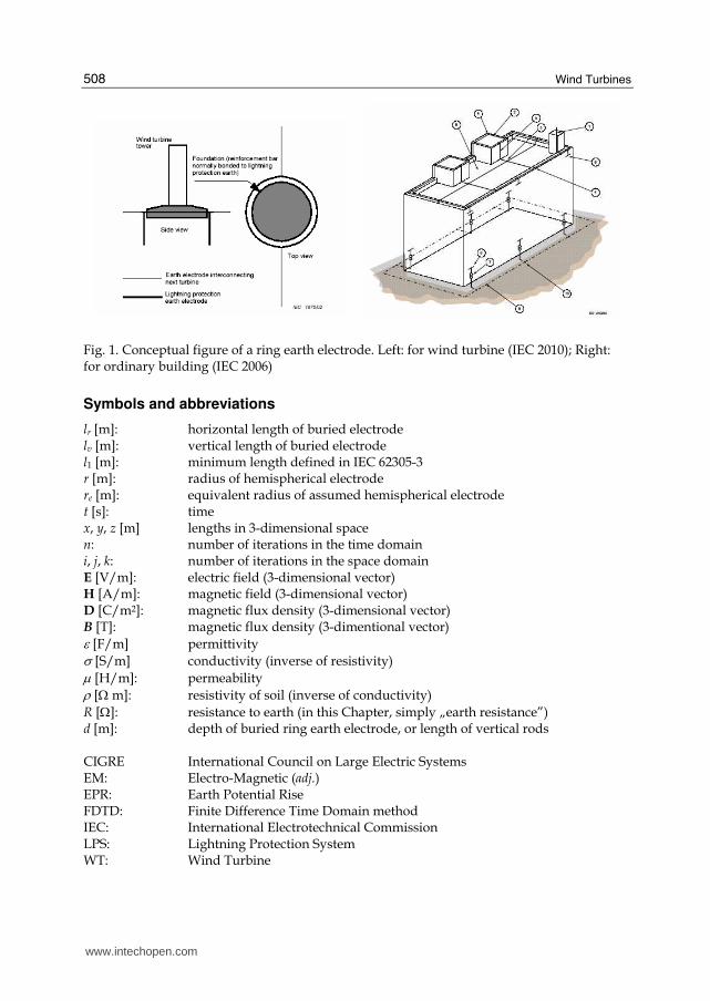
Fig. 1. Conceptual figure of a ring earth electrode. Left: for wind turbine (IEC 2010); Right: for ordinary building (IEC 2006)
Symbols and abbreviations
lr [m]: horizontal length of buried electrode lv [m]: vertical length of buried electrode l1 [m]: minimum length defined in IEC 62305-3 r [m]: radius of hemispherical electrode re [m]: equivalent radius of assumed hemispherical electrode t [s]: time x, y, z [m] lengths in 3-dimensional space n: number of iterations in the time domain i, j, k: number of iterations in the space domain E [V/m]: electric field (3-dimensional vector) H [A/m]: magnetic field (3-dimensional vector) D [C/m2]: magnetic flux density (3-dimensional vector) B [T]: magnetic flux density (3-dimentional vector) ε [F/m] permittivity σ [S/m] conductivity (inverse of resistivity) μ [H/m]: permeability ρ [Ω m]: resistivity of soil (inverse of conductivity)
R [Ω]: resistance to earth (in this Chapter, simply „earth resistance”) d [m]: depth of buried ring earth electrode, or length of vertical rods CIGRE International Council on Large Electric Systems EM: Electro-Magnetic (adj.) EPR: Earth Potential Rise FDTD: Finite Difference Time Domain method IEC: International Electrotechnical Commission LPS: Lightning Protection System WT: Wind Turbine
www.intechopen.com
Electromagnetic Calculation of a Wind Turbine Earthing System
509
2. Basic concept of an earthing system for lightning protection
2.1 What is “earthing”? Before starting a discussion on wind turbine earthing, we need to review briefly the meaning of „earthing” to ensure a common understanding. When people use the word „earthing” (or „grounding”) in every day conversation, they probably mean that an electric device should be connected to the earth (ground) via a cable or a rod to achieve „zero voltage” at an earth terminal (or a chassis). This understanding may be quite acceptable for „normal cases” like electric leakage protection or an electric noise reduction. However, strictly speaking, „zero voltage” cannot be realised by earthing. This fact would be very evident in an „abnormal” case such as surge invasion due to lightning. Theoretically, the earth resistance of an electrode can be determined by the integration of a function including the resistivity of the surrounding soil and the size (i.e. radius) of the electrode. As the resistivity of the actual soil can never be zero, it is a natural consequence that the earth resistance can never be zero. Incidentally, it is obvious that the earth voltage V [V] of the terminal of the earthing electrode is solved using the simple Ohm’s law of V = IR, where I [A] is an inrush current such as a lightning surge. Suppose the earth resistance is
10 Ω, which is normally the safe value as defined in many standards and regulations, then if a lightning current of 30 kA is the inrush current to the earthing electrode, the earthing voltage of the electrode, namely an earthing potential rise (EPR), would rise to 300 kV! This is a basic concept in earthing for a LPS. It follows from the above description that the best way to implement a LPS is to reduce the earth resistance to as low as possible. However, in an actual WT site, in addition to the conventional electrical equipment the cost of reducing the earth resistance may be excessive because of the need for additional construction work involving large or long conductive materials, a significant amount of labour and special heavy machinery. Thus, many international or domestic standards and regulations normally set the minimum safe value
for the steady resistance to be 10 Ω. It is therefore important to estimate the resistance of the earthing system as accurately as possible before WT construction.
2.2 Theory of earth resistance Theoretically, earth resistance is a function of the resistivity of the surrounding soil and the size of the electrode. As a normal resistance is required, earth resistance R is defined as follows (note that the range of integration is from the origin infinity):
0
.( )
R drS r
ρ∞= ∫ (1)
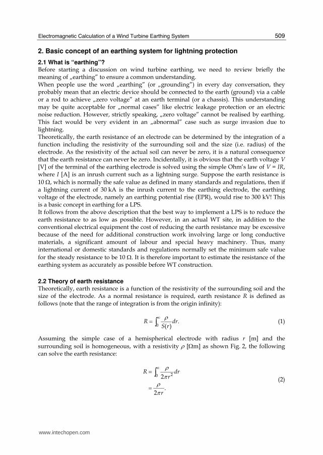
Assuming the simple case of a hemispherical electrode with radius r [m] and the
surrounding soil is homogeneous, with a resistivity ρ [Ωm] as shown Fig. 2, the following can solve the earth resistance:
20 2
.2
R drr
r
ρπρ
π
∞==∫
(2)
www.intechopen.com
Wind Turbines
510
The earth resistance therefore is a function of the resistivity of the surrounding soil and the size (i.e. radius) of the electrode. As shown in the above equation, there must be an earth resistance with a non-zero value.
Fig. 2. Conceptual illustration of earth resistance in case of a hemispherical electrode
Similarly, the earth resistance of a vertical conductor of radius r [m] and length (depth) d [m] buried in the soil is approximately defined as
2
ln ,2
dR
d r
ρπ
⎛ ⎞= ⎜ ⎟⎝ ⎠ (3)
and that of a ring earth electrode whose outer radius, inner radius and buried depth is ro, ri, and d [m] is proposed by Sunde (Sunde 1949) as follows:
8
ln .2 2
o
o i
rR
r r d
ρπ
⎛ ⎞= ⎜ ⎟⎜ ⎟⎝ ⎠ (4)
Note that the above equations are just theoretical or approximate calculating equations for the typical shapes of various types of electrode. As it is normal that varying types of electrodes are combined in practical use, it is difficult to estimate correctly an earthing value of an arbitrary electrode with a complex shape. Although there are several theories concerning a combination effect or an adjacent effect, no equations have been proposed to universally express a complex shape. Furthermore, it is not always satisfactory to consider only the steady value of the earth resistance. For EPR, it is important to consider transient
voltage under a lightning impulse lasting up to 10 μs. This is why numerical calculations including the FDTD method are important to calculate the earthing electrode and design an accurate earthing system for LPS.
2.3 Wind turbine earthing system described in IEC standards According to IEC 61400-24, a „Type A arrangement” (with vertical and/or horizontal electrode) and „Type B arrangement” (with ring earth electrode) are recommended for wind
r
x dx
earth surface
ρsoil
earth current
www.intechopen.com
Electromagnetic Calculation of a Wind Turbine Earthing System
511
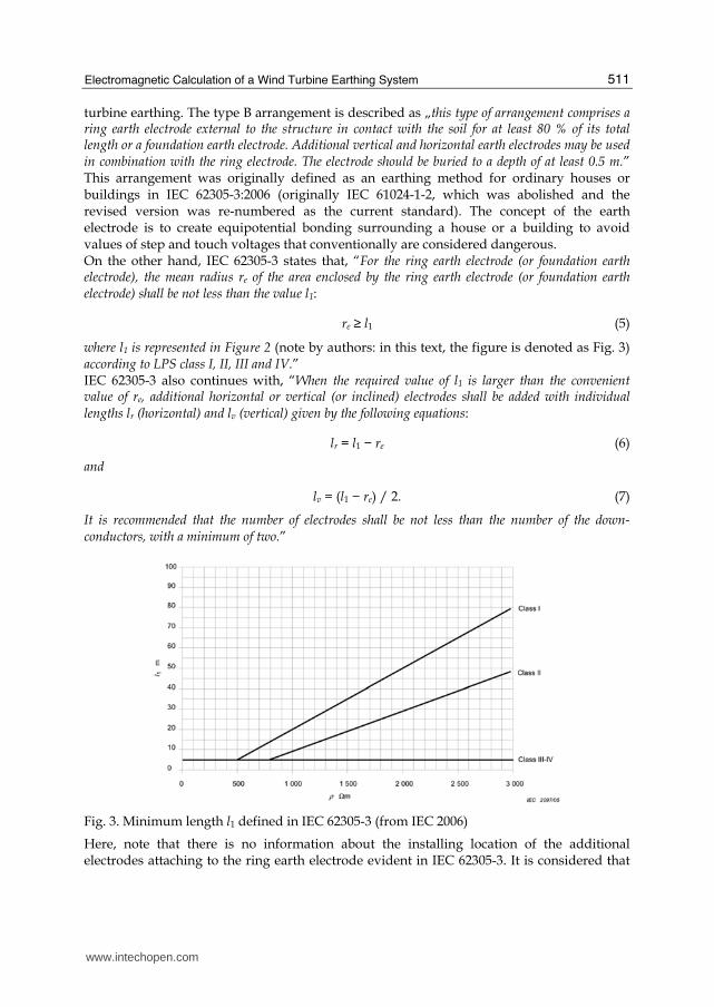
turbine earthing. The type B arrangement is described as „this type of arrangement comprises a ring earth electrode external to the structure in contact with the soil for at least 80 % of its total length or a foundation earth electrode. Additional vertical and horizontal earth electrodes may be used in combination with the ring electrode. The electrode should be buried to a depth of at least 0.5 m.” This arrangement was originally defined as an earthing method for ordinary houses or buildings in IEC 62305-3:2006 (originally IEC 61024-1-2, which was abolished and the revised version was re-numbered as the current standard). The concept of the earth electrode is to create equipotential bonding surrounding a house or a building to avoid values of step and touch voltages that conventionally are considered dangerous. On the other hand, IEC 62305-3 states that, “For the ring earth electrode (or foundation earth electrode), the mean radius re of the area enclosed by the ring earth electrode (or foundation earth electrode) shall be not less than the value l1:
re ≥ l1 (5)
where l1 is represented in Figure 2 (note by authors: in this text, the figure is denoted as Fig. 3) according to LPS class I, II, III and IV.” IEC 62305-3 also continues with, “When the required value of l1 is larger than the convenient value of re, additional horizontal or vertical (or inclined) electrodes shall be added with individual lengths lr (horizontal) and lv (vertical) given by the following equations:
lr = l1 − re (6)
and
lv = (l1 − re) / 2. (7)
It is recommended that the number of electrodes shall be not less than the number of the down-conductors, with a minimum of two.”
Fig. 3. Minimum length l1 defined in IEC 62305-3 (from IEC 2006)
Here, note that there is no information about the installing location of the additional electrodes attaching to the ring earth electrode evident in IEC 62305-3. It is considered that
www.intechopen.com
Wind Turbines
512
the reason for this is that it does not matter whether the additional electrodes are attached to a conventional structure such as a building because the structure has relatively wide foundations. Moreover, it is normal for the ring earth electrode to be installed relatively close to the foundations because of land area limitations. In contrast, the foundation of a wind turbine is comparatively small and therefore the ring earth electrode must be installed as far away from the original foundation as possible. In this situation, it is possible that the installed location of the additional electrodes could be very sensitive. In this chapter, the minimum length of the electrodes will be researched in detail. A numerical calculation using the FDTD (Finite Difference Time Domain) method is employed to clarify how the size and the location of the attachment of the additional electrodes will affect the earth resistance. This study not only shows the unexpected inappropriate cases but also proposes an improved recommendation, particularly for a wind turbine earthing system.
3. FDTD electromagnetic calculation
A Finite Difference Time Domain (FDTD) method is a computing calculation algorithm in which Maxwell’s electromagnetic equations are computationally treated as difference equations in both the time and space domains. While the FDTD method was initially applied to electromagnetic field analysis around an antenna (Yee 1966, Kunz 1993), with the increased CPU power in PC machines, various investigations into high voltage engineering including lightning surge and earth system analysis have also employed the algorithm.
3.1 Theory of Fine Difference Time Domain (FDTD) method In the FDTD method, an analysis domain surrounding a wave source and the measured objects is assumed. The domain is divided into a small rectangular solid, which is called a „cell”. The following Maxwell differential equations, Eqs. (8) and (9), are directly applied to all the cells.
( ) ( ),rot ,
tt
t
∂∂= − B r
E r , (8)
( ) ( ) ( ),rot , ,
tt t
t
∂∂= − +D r
H r J r . (9)
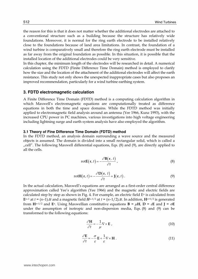
In the actual calculation, Maxwell’s equations are arranged as a first-order central difference approximation called Yee’s algorithm (Yee 1966) and the magnetic and electric fields are calculated step by step as shown in Fig. 4. For example, an electric field En is calculated from En–1 at t = (n–1)Δt and a magnetic field Hn–1/2 at t = (n–1/2)Δt. In addition, Hn+1/2 is generated
from Hn–1/2 and En. Using Maxwellian constitutive equations B = μH, D = εE and J = σE under the assumption of isotropic and non-dispersion media, Eqs. (8) and (9) can be transformed to the following equations:
1
t
∂∂ μ= − ∇×H
E , (10)
1
t
∂ σ∂ ε ε= − + ∇×E
E H . (11)
www.intechopen.com
Electromagnetic Calculation of a Wind Turbine Earthing System
513
Fig. 4. Arrangement of the electric field E and magnetic field H in the time difference domain
Eqs. (10) and (11) can be converted to Eqs. (12) and (13) by difference approximation.
1 1
2 2 1n n
n
t μ+ −− = − ∇×Δ
H HE , (12)
1 112 2
1n n n n
t
σε ε
− − −− = − + ∇×ΔE E
E H . (13)
So, a recurrence formula for the magnetic field H can be simply expressed as follows:
1 1
2 2n n
nt
μ+ − Δ− = − ∇×H H E . (14)
On the other hand, in the electric field, En–1/2 cannot exist because each electric field is
defined only at integer time. Consequently, approximating it as the average of En and En–1, a
recurrence formula for the electric field E is given as follows:
1
1 2
12
1 12 2
nn n
t t
t t
σε εσ σε ε
−−Δ Δ−− = ∇×Δ Δ+ +
E E H . (15)
As can be seen from Eqs. (14) and (15), in the FDTD methods, the electric field En is
generated from the previous half step of the electric field En–1 at t = (n–1)Δt and the magnetic
field Hn–1/2 at t = (n–1/2)Δt. Likewise, the magnetic field Hn+1/2 is calculated from the
previous half step of the electric field En and the magnetic field Hn–1/2.
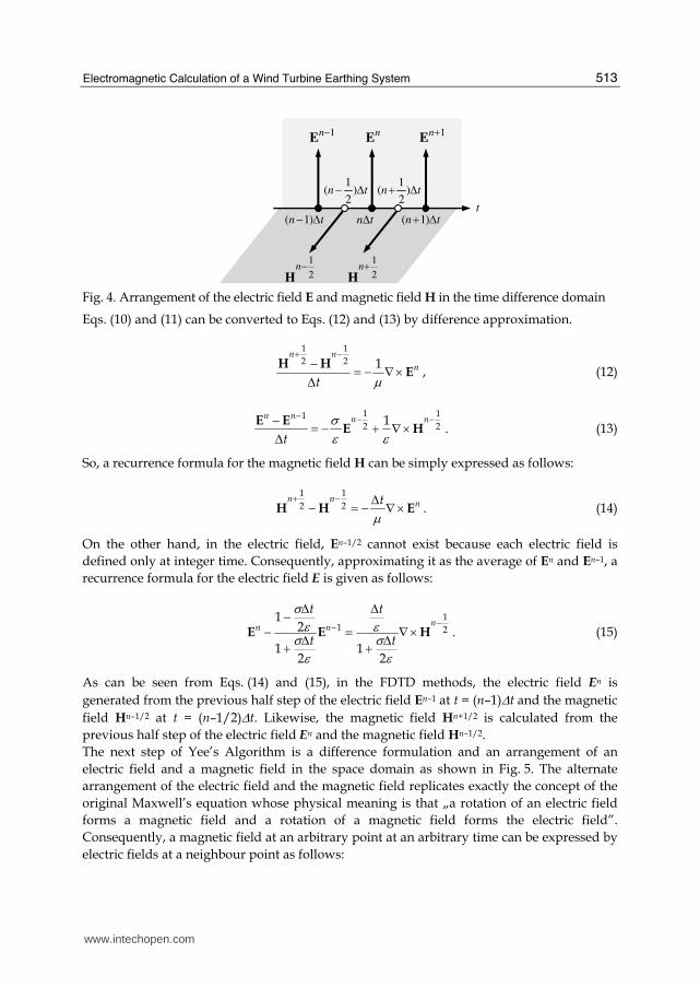
The next step of Yee’s Algorithm is a difference formulation and an arrangement of an
electric field and a magnetic field in the space domain as shown in Fig. 5. The alternate
arrangement of the electric field and the magnetic field replicates exactly the concept of the
original Maxwell’s equation whose physical meaning is that „a rotation of an electric field
forms a magnetic field and a rotation of a magnetic field forms the electric field”.
Consequently, a magnetic field at an arbitrary point at an arbitrary time can be expressed by
electric fields at a neighbour point as follows:
t
En+1
En
(n−1)Δt nΔt (n+1)Δt
(n+ 1
2)Δt(n− 1
2)Δt
H
n+ 1
2H
n−1
2
En−1
www.intechopen.com
Wind Turbines
514
1 1
2 21 1 1 1
, , , ,2 2 2 2
1 1 1 1, 1, , , , , 1 , ,
2 2 2 2.
n n
x x
n n n nz z y y
H i j k H i j k
E i j k E i j k E i j k E i j kt
y zμ
+ −⎛ ⎞ ⎛ ⎞+ + − + +⎜ ⎟ ⎜ ⎟⎝ ⎠ ⎝ ⎠⎡ ⎤⎛ ⎞ ⎛ ⎞ ⎛ ⎞ ⎛ ⎞+ + − + + + − +⎜ ⎟ ⎜ ⎟ ⎜ ⎟ ⎜ ⎟⎢ ⎥Δ ⎝ ⎠ ⎝ ⎠ ⎝ ⎠ ⎝ ⎠⎢ ⎥= − −Δ Δ⎢ ⎥⎢ ⎥⎣ ⎦
(16)
Fig. 5. Arrangement in the difference space domain of an electric field E and a magnetic field H
In the same manner, it is possible to calculate a magnetic field at an arbitrary point at an arbitrary time as:
1
1 1
2 2
1 1
2 2
11 12, , , ,2 21
2
1 1 1 1, , , ,1
2 2 2 22
12
1 1 1 1, , , ,
2 2 2 2.
n nz z
n n
y y
n n
x x
t
E i j k E i j kt
t H i j k H i j k
t x
H i j k H i j k
y
σεσε
σεσε
−
− −
− −
Δ−⎛ ⎞ ⎛ ⎞+ − +⎜ ⎟ ⎜ ⎟Δ⎝ ⎠ ⎝ ⎠+⎡ ⎛ ⎞ ⎛ ⎞Δ ⎢ + + − − +− ⎜ ⎟ ⎜ ⎟⎝ ⎠ ⎝ ⎠⎢= − ⎢Δ Δ+ ⎢⎢⎣
⎤⎛ ⎞ ⎛ ⎞ ⎥+ + − − +⎜ ⎟ ⎜ ⎟⎝ ⎠ ⎝ ⎠ ⎥− ⎥Δ ⎥⎥⎦
(17)
i, j +1, k +1( )
i+1, j +1, k +1( )i+1, j, k +1( )
i, j, k +1( )
i, j +1, k( )
i+1, j +1, k( )i+1, j, k( )
i, j, k( )
Hx
Hx
HyHy
Hz
Hz
ExEx
ExEx
Ey
Ey
Ey
Ey
Ez
Ezz
y
x
Δy
Δx
ΔzEz
Ez
www.intechopen.com
Electromagnetic Calculation of a Wind Turbine Earthing System
515
3.2 Applications of the FDTD method for lightning protection of a wind turbine As mentioned above, early applications of the FDTD method focused on the electromagnetic analysis of antenna. Some of the earliest reports on applying it to electric power apparatus were published by Tanabe, which discussed the electromagnetic field propagation in soil from a buried vertical rod when a lightning surge was imposed (Tanabe 2000, Tanabe 2001). As the calculation power of PCs has dramatically increased since early 2000, many reports and papers on surge analysis using the FDTD method have been published, especially by Japanese researchers. Noda proposed a novel method, which described a thin wire, such as an overhead wire, and an underground cable in distribution lines (Noda 2002). Moreover, a thin-wire representation in a non-quadric grid (Taniguchi 2008a), and an algorithm to calculate a circular object in cylindrical coordinates (Taniguchi 2008b) were initially proposed and discussed. A research group in the Central Research Institute of Electric Power Industry (CRIEPI), Japan developed a commercial software named „VSTL“ (Virtual Surge Test Lab.), which specialised in the surge analysis of electric power apparatus based on the FDTD method (Noda 2005). Only a few papers on applications to WT-LPS have been reported since the start of 2000. Yamamoto investigated the state of surge propagation in a wind turbine including blades, down-conductors, the nacelle, the tower, and an earthing system, comparing actual measurements using a downsized WT model and FDTD calculations (Yamamoto 2009, Yamamoto 2010). An investigation group of Doshisha University, Japan, calculated the surge propagation from a turbine when struck by lightning, to another turbine via a buried interconnecting earthing wire (Nagao 2009). The authors’ investigation group also stored knowledge and results on surge analysis and an earthing design of a WT (Yasuda 2007a, Yasuda 2007b, Fujii 2009). In the following sections, the latest results by the authors will be presented. Numerical calculations on WT-LPS are not limited to the FDTD method. Several early researchers have raised important questions about WT earthing and its LPS. A report from a joint research group at UMIST (University of Manchester Institute of Technology) and the National Technical University of Athens is one of the earliest on the subject (Hatziargyriou 1997, Cotton 1997, Cotton 1999, Lorenzou 2000), where they compared the results by EMTP and a software package named CEDGS based on a numerical integration method in the frequency domain. Good examples of later investigations included the use of the MoM (moment method) (Lewke 2006), the FEM (finite element method) (Muto 2010), CEDGS (Kontargyri 2005, Elmghairbi 2009), EMTP (electromagnetic transient program) and its related software (Yasuda 2008), and an algebraic analysis based on a travelling-wave theory (Hermoso 2006, Sekioka 2010).
4. Analysis of Wind Turbine Earthing using FDTD Calculation I: (Evaluation of the effect of a ring earth electrode)
As mentioned in the Introduction, a ring earth electrode was originally installed for use with conventional buildings and households to reduce a touch and a step voltage mainly for human safety. Though the original purpose was effective for a WT earthing system, the ring earth electrode was expected to have the effect of reducing not only a touch and a step voltage but also a steady resistance and an earth potential rise (EPR). This is because a ring electrode for WT is normally installed in a much wider area than for conventional buildings and households (see Fig. 1 and relative discussion in Sec. 1). In this section, the evaluation of
www.intechopen.com
Wind Turbines
516
the effect of the ring earth electrode for WT is discussed especially from the aspect of a steady resistance and an EPR. The results introduced in this section are mainly the outcomes from the authors’ paper (Fujii 2009).
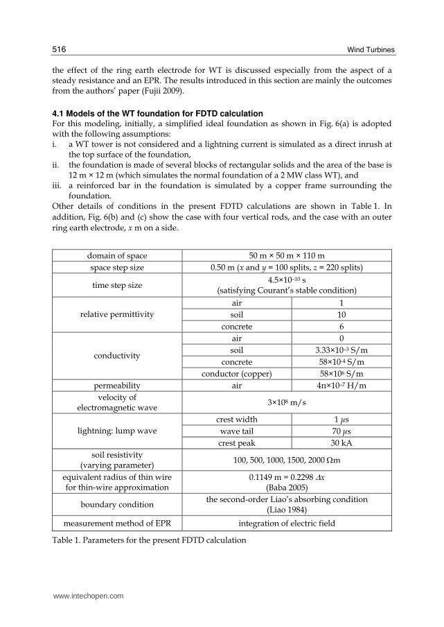
4.1 Models of the WT foundation for FDTD calculation For this modeling, initially, a simplified ideal foundation as shown in Fig. 6(a) is adopted with the following assumptions: i. a WT tower is not considered and a lightning current is simulated as a direct inrush at
the top surface of the foundation, ii. the foundation is made of several blocks of rectangular solids and the area of the base is
12 m × 12 m (which simulates the normal foundation of a 2 MW class WT), and iii. a reinforced bar in the foundation is simulated by a copper frame surrounding the
foundation. Other details of conditions in the present FDTD calculations are shown in Table 1. In
addition, Fig. 6(b) and (c) show the case with four vertical rods, and the case with an outer
ring earth electrode, x m on a side.
domain of space 50 m × 50 m × 110 m
space step size 0.50 m (x and y = 100 splits, z = 220 splits)
time step size 4.5×10⁻¹⁰ s
(satisfying Courant’s stable condition)
air 1
soil 10 relative permittivity
concrete 6
air 0
soil 3.33×10⁻³ S/m
concrete 58×10-4 S/m conductivity
conductor (copper) 58×106 S/m
permeability air 4π×10–7 H/m
velocity of electromagnetic wave
3×10⁸ m/s
crest width 1 μs
wave tail 70 μs lightning: lump wave
crest peak 30 kA
soil resistivity (varying parameter)
100, 500, 1000, 1500, 2000 Ωm
equivalent radius of thin wire for thin-wire approximation
0.1149 m = 0.2298 Δx (Baba 2005)
boundary condition the second-order Liao’s absorbing condition
(Liao 1984)
measurement method of EPR integration of electric field
Table 1. Parameters for the present FDTD calculation
www.intechopen.com
Electromagnetic Calculation of a Wind Turbine Earthing System
517
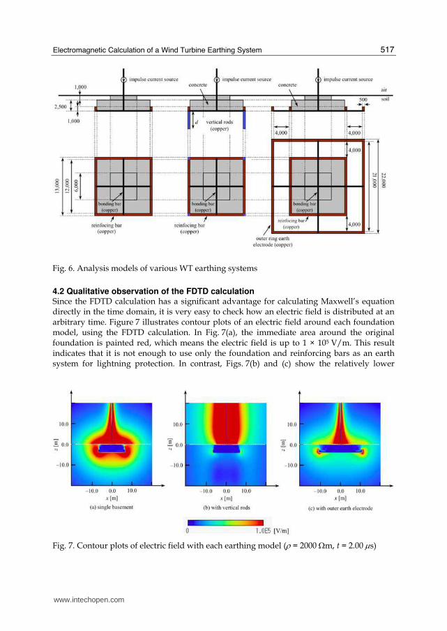
Fig. 6. Analysis models of various WT earthing systems
4.2 Qualitative observation of the FDTD calculation Since the FDTD calculation has a significant advantage for calculating Maxwell’s equation directly in the time domain, it is very easy to check how an electric field is distributed at an arbitrary time. Figure 7 illustrates contour plots of an electric field around each foundation model, using the FDTD calculation. In Fig. 7(a), the immediate area around the original foundation is painted red, which means the electric field is up to 1 × 10⁵ V/m. This result indicates that it is not enough to use only the foundation and reinforcing bars as an earth system for lightning protection. In contrast, Figs. 7(b) and (c) show the relatively lower
Fig. 7. Contour plots of electric field with each earthing model (ρ = 2000 Ωm, t = 2.00 μs)
www.intechopen.com
Wind Turbines
518
electric field in the soil due to the auxiliary vertical rods or the outer ring earth electrode (Note that the buried vertical rods are invisible in Fig. 7(b) because the graph is a cross-section at y = 0). This suggests effective suppression of EPR during a lightning surge can be expected when an auxiliary electrode is employed. Note that, from the original view point of the touch and step voltage, the result of the case with the ring earth electrode (Fig. 7(c)) shows that the potential difference on the earth surface clearly improved because of the ring electrode.
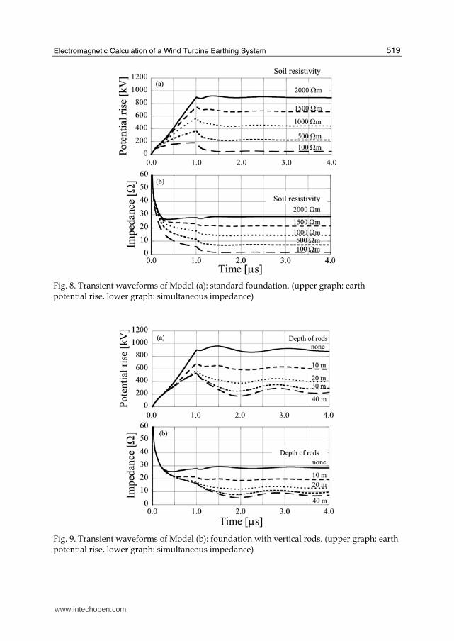
4.3 Transient analysis of the various earthing systems 4.3.1 Transient analysis for the original foundation case To observe the FDTD results in more detail, the calculated waveforms of EPR (curves of simultaneous potentials on the top surface of the foundation) and the simultaneous impedance (curves of simultaneous quotients of simultaneous potentials and simultaneous input current) of the earthing system are as illustrated in Figs. 8, 9 and 10. In this analysis,
the parameter of soil resistivity is assumed to be 100, 500, 1000, 1500 and 2000 Ωm.
Although the waveforms in Fig. 8(b) have steep peaks up to 60 Ω at about t = 0.1 μs, they are not considered essential in the present discussion. This is because they are determined by division calculations whose denominators are almost zero at that time and may have almost no influence to the potential rise at the time. In fact, it is evident that the transient elevation
of the EPR waveform at t = 0.1 μs cannot be seen in Fig. 8(a). The problem should be considered as the special case of a very steep current rise in sub-micro seconds at a
subsequent lightning stroke. Disregarding the steep peak at about t = 0.1 μs, it is shown that
curves in cases of less than 2000 Ωm have creeping inductive characteristics, and that the
case of 2000 Ωm has a slightly capacitive characteristics before t = 1.0 μs. After t = 1.0 μs, all the curves clearly have resistive characteristics with a flat and stable behaviour.
4.3.2 Transient analysis for the case with vertical rods In contrast, Fig. 9 shows the results from the case with four vertical rods as shown in Fig. 6(b). In the present analysis, the varying parameter was set to be d [m] which was the buried depth of each vertical rod and the calculations were performed under the condition
of a soil resistivity of 2000 Ωm. The calculation was performed to clarify the effect of vertical rods. As can be seen in Fig. 9(a), with every parameter EPR curves indicate the effect of vertical rods compared with the case without rods. It is also found that the simultaneous impedance curves have moderate peaks and show slight inductivity. However, in the case of rods of more than 30 m, the effect of holding the EPR down is not seen any more and steady values of impedance i.e. earth resistance converge to a standard value. This is very similar to a result from a conventional transmission tower foundation with vertical rods. Thus, it becomes clear that vertical rods are effective for a WT-LPS for moderating both steady resistance and a rise in inductive potential. However, rods that are too long may not be cost-effective or realistic for reducing EPR and the steady earth resistance.
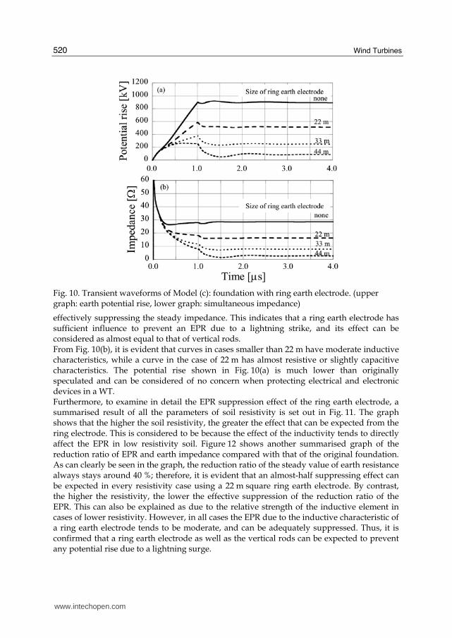
4.3.3 Transient analysis in the case with a ring earth electrode The result in the case with a ring earth electrode as shown in Fig. 6(c) is presented in Fig. 10. In this analysis, the varying parameter is a side of the square electrode. Comparing the curves in the two graphs, it is evident that the larger the ring electrode, the lower the EPR,
www.intechopen.com
Electromagnetic Calculation of a Wind Turbine Earthing System
519
Fig. 8. Transient waveforms of Model (a): standard foundation. (upper graph: earth potential rise, lower graph: simultaneous impedance)
Fig. 9. Transient waveforms of Model (b): foundation with vertical rods. (upper graph: earth potential rise, lower graph: simultaneous impedance)
www.intechopen.com
Wind Turbines
520
Fig. 10. Transient waveforms of Model (c): foundation with ring earth electrode. (upper graph: earth potential rise, lower graph: simultaneous impedance)
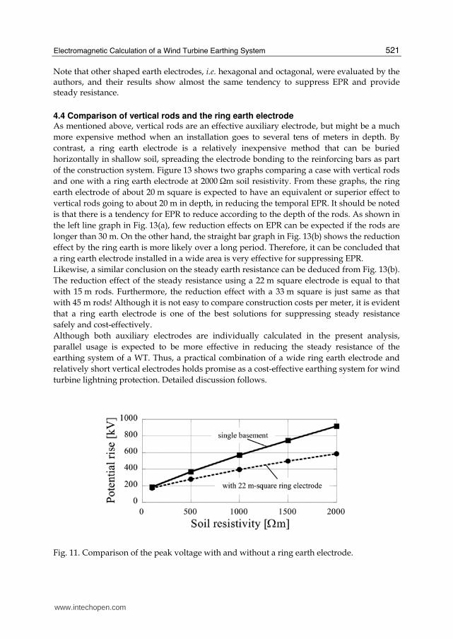
effectively suppressing the steady impedance. This indicates that a ring earth electrode has sufficient influence to prevent an EPR due to a lightning strike, and its effect can be considered as almost equal to that of vertical rods. From Fig. 10(b), it is evident that curves in cases smaller than 22 m have moderate inductive characteristics, while a curve in the case of 22 m has almost resistive or slightly capacitive characteristics. The potential rise shown in Fig. 10(a) is much lower than originally speculated and can be considered of no concern when protecting electrical and electronic devices in a WT. Furthermore, to examine in detail the EPR suppression effect of the ring earth electrode, a summarised result of all the parameters of soil resistivity is set out in Fig. 11. The graph shows that the higher the soil resistivity, the greater the effect that can be expected from the ring electrode. This is considered to be because the effect of the inductivity tends to directly affect the EPR in low resistivity soil. Figure 12 shows another summarised graph of the reduction ratio of EPR and earth impedance compared with that of the original foundation. As can clearly be seen in the graph, the reduction ratio of the steady value of earth resistance always stays around 40 %; therefore, it is evident that an almost-half suppressing effect can be expected in every resistivity case using a 22 m square ring earth electrode. By contrast, the higher the resistivity, the lower the effective suppression of the reduction ratio of the EPR. This can also be explained as due to the relative strength of the inductive element in cases of lower resistivity. However, in all cases the EPR due to the inductive characteristic of a ring earth electrode tends to be moderate, and can be adequately suppressed. Thus, it is confirmed that a ring earth electrode as well as the vertical rods can be expected to prevent any potential rise due to a lightning surge.
www.intechopen.com
Electromagnetic Calculation of a Wind Turbine Earthing System
521
Note that other shaped earth electrodes, i.e. hexagonal and octagonal, were evaluated by the authors, and their results show almost the same tendency to suppress EPR and provide steady resistance.
4.4 Comparison of vertical rods and the ring earth electrode As mentioned above, vertical rods are an effective auxiliary electrode, but might be a much
more expensive method when an installation goes to several tens of meters in depth. By
contrast, a ring earth electrode is a relatively inexpensive method that can be buried
horizontally in shallow soil, spreading the electrode bonding to the reinforcing bars as part
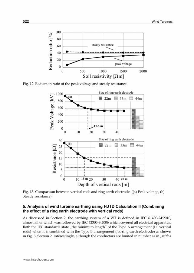
of the construction system. Figure 13 shows two graphs comparing a case with vertical rods
and one with a ring earth electrode at 2000 Ωm soil resistivity. From these graphs, the ring
earth electrode of about 20 m square is expected to have an equivalent or superior effect to
vertical rods going to about 20 m in depth, in reducing the temporal EPR. It should be noted
is that there is a tendency for EPR to reduce according to the depth of the rods. As shown in
the left line graph in Fig. 13(a), few reduction effects on EPR can be expected if the rods are
longer than 30 m. On the other hand, the straight bar graph in Fig. 13(b) shows the reduction
effect by the ring earth is more likely over a long period. Therefore, it can be concluded that
a ring earth electrode installed in a wide area is very effective for suppressing EPR.
Likewise, a similar conclusion on the steady earth resistance can be deduced from Fig. 13(b).
The reduction effect of the steady resistance using a 22 m square electrode is equal to that
with 15 m rods. Furthermore, the reduction effect with a 33 m square is just same as that
with 45 m rods! Although it is not easy to compare construction costs per meter, it is evident
that a ring earth electrode is one of the best solutions for suppressing steady resistance
safely and cost-effectively.
Although both auxiliary electrodes are individually calculated in the present analysis,
parallel usage is expected to be more effective in reducing the steady resistance of the
earthing system of a WT. Thus, a practical combination of a wide ring earth electrode and
relatively short vertical electrodes holds promise as a cost-effective earthing system for wind
turbine lightning protection. Detailed discussion follows.
Fig. 11. Comparison of the peak voltage with and without a ring earth electrode.
www.intechopen.com
Wind Turbines
522
Fig. 12. Reduction ratio of the peak voltage and steady resistance.
Fig. 13. Comparison between vertical rods and ring earth electrode. ((a) Peak voltage, (b) Steady resistance).
5. Analysis of wind turbine earthing using FDTD Calculation II (Combining the effect of a ring earth electrode with vertical rods)
As discussed in Section 2, the earthing system of a WT is defined in IEC 61400-24:2010, almost all of which was followed by IEC 62305-3:2006 which covered all electrical apparatus. Both the IEC standards state „the minimum length” of the Type A arrangement (i.e. vertical rods) when it is combined with the Type B arrangement (i.e. ring earth electrode) as shown in Fig. 3, Section 2. Interestingly, although the conductors are limited in number as in „with a
www.intechopen.com
Electromagnetic Calculation of a Wind Turbine Earthing System
523
minimum of two” to determine the minimum length of the Type A arrangement, the location of the conductors is not stated in the standards at all. This would not be a serious problem for conventional buildings and households or power apparatus such as power stations and power plants, but, is it really suitable for WTs even with new apparatus with a special shape and the special characteristic of a LPS? Though a few reports have noted the problem, the essential questions do not appear to have been resolved. As mentioned previously, a WT sometimes has a wide ring earth electrode compared to its small foundation. This is because the area occupied by a WT is normally much larger than that of a conventional building and it is relatively easy to bury electrodes horizontally. Moreover, compared with the conventional power apparatus, which normally has a mesh electrode, it is not realistic for the total site of the WT or a wind farm to be covered with a mesh electrode due to the high construction costs. The question arises as to whether the location of the installed conductors really affects the determination of the minimum length and what combination of the ring electrode and vertical rods has the most effect on LPS for a WT. These questions need to be resolved to establish safe countermeasures against lightning accidents. The discussion in this section is mainly based on the authors’ paper (Yasuda 2007b).
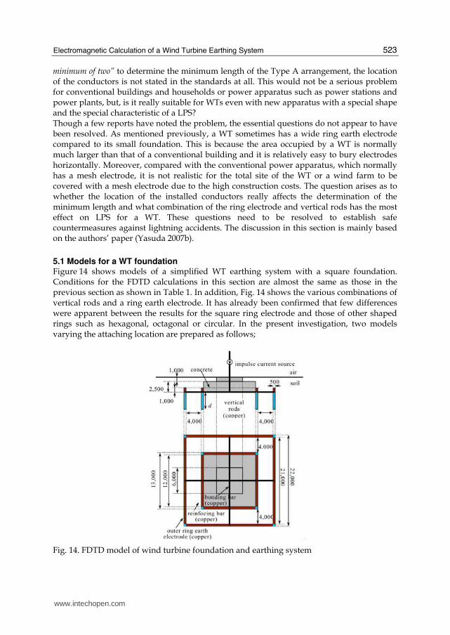
5.1 Models for a WT foundation Figure 14 shows models of a simplified WT earthing system with a square foundation. Conditions for the FDTD calculations in this section are almost the same as those in the previous section as shown in Table 1. In addition, Fig. 14 shows the various combinations of vertical rods and a ring earth electrode. It has already been confirmed that few differences were apparent between the results for the square ring electrode and those of other shaped rings such as hexagonal, octagonal or circular. In the present investigation, two models varying the attaching location are prepared as follows;
Fig. 14. FDTD model of wind turbine foundation and earthing system
www.intechopen.com
Wind Turbines
524
Case I Case II Case III
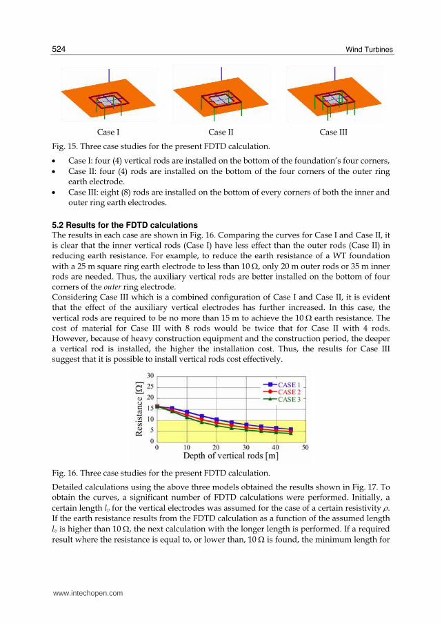
Fig. 15. Three case studies for the present FDTD calculation.
• Case I: four (4) vertical rods are installed on the bottom of the foundation’s four corners,
• Case II: four (4) rods are installed on the bottom of the four corners of the outer ring earth electrode.
• Case III: eight (8) rods are installed on the bottom of every corners of both the inner and outer ring earth electrodes.
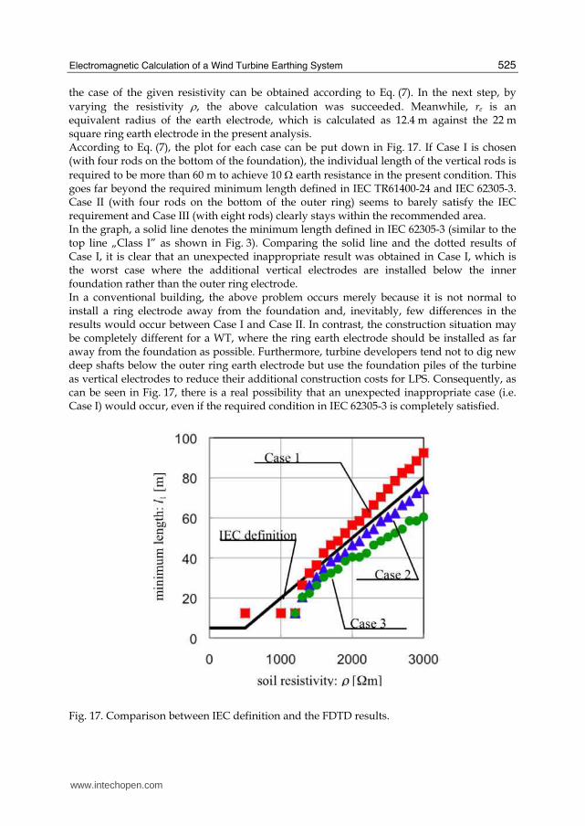
5.2 Results for the FDTD calculations The results in each case are shown in Fig. 16. Comparing the curves for Case I and Case II, it is clear that the inner vertical rods (Case I) have less effect than the outer rods (Case II) in reducing earth resistance. For example, to reduce the earth resistance of a WT foundation
with a 25 m square ring earth electrode to less than 10 Ω, only 20 m outer rods or 35 m inner rods are needed. Thus, the auxiliary vertical rods are better installed on the bottom of four corners of the outer ring electrode. Considering Case III which is a combined configuration of Case I and Case II, it is evident that the effect of the auxiliary vertical electrodes has further increased. In this case, the
vertical rods are required to be no more than 15 m to achieve the 10 Ω earth resistance. The cost of material for Case III with 8 rods would be twice that for Case II with 4 rods. However, because of heavy construction equipment and the construction period, the deeper a vertical rod is installed, the higher the installation cost. Thus, the results for Case III suggest that it is possible to install vertical rods cost effectively.
Fig. 16. Three case studies for the present FDTD calculation.
Detailed calculations using the above three models obtained the results shown in Fig. 17. To obtain the curves, a significant number of FDTD calculations were performed. Initially, a
certain length lv for the vertical electrodes was assumed for the case of a certain resistivity ρ. If the earth resistance results from the FDTD calculation as a function of the assumed length
lv is higher than 10 Ω, the next calculation with the longer length is performed. If a required
result where the resistance is equal to, or lower than, 10 Ω is found, the minimum length for
www.intechopen.com
Electromagnetic Calculation of a Wind Turbine Earthing System
525
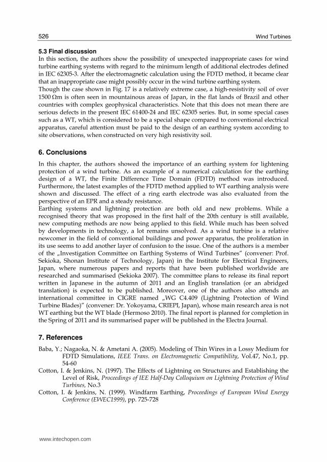
the case of the given resistivity can be obtained according to Eq. (7). In the next step, by
varying the resistivity ρ, the above calculation was succeeded. Meanwhile, re is an equivalent radius of the earth electrode, which is calculated as 12.4 m against the 22 m square ring earth electrode in the present analysis. According to Eq. (7), the plot for each case can be put down in Fig. 17. If Case I is chosen (with four rods on the bottom of the foundation), the individual length of the vertical rods is
required to be more than 60 m to achieve 10 Ω earth resistance in the present condition. This goes far beyond the required minimum length defined in IEC TR61400-24 and IEC 62305-3. Case II (with four rods on the bottom of the outer ring) seems to barely satisfy the IEC requirement and Case III (with eight rods) clearly stays within the recommended area. In the graph, a solid line denotes the minimum length defined in IEC 62305-3 (similar to the top line „Class I” as shown in Fig. 3). Comparing the solid line and the dotted results of Case I, it is clear that an unexpected inappropriate result was obtained in Case I, which is the worst case where the additional vertical electrodes are installed below the inner foundation rather than the outer ring electrode. In a conventional building, the above problem occurs merely because it is not normal to install a ring electrode away from the foundation and, inevitably, few differences in the results would occur between Case I and Case II. In contrast, the construction situation may be completely different for a WT, where the ring earth electrode should be installed as far away from the foundation as possible. Furthermore, turbine developers tend not to dig new deep shafts below the outer ring earth electrode but use the foundation piles of the turbine as vertical electrodes to reduce their additional construction costs for LPS. Consequently, as can be seen in Fig. 17, there is a real possibility that an unexpected inappropriate case (i.e. Case I) would occur, even if the required condition in IEC 62305-3 is completely satisfied.
Fig. 17. Comparison between IEC definition and the FDTD results.
www.intechopen.com
Wind Turbines
526
5.3 Final discussion In this section, the authors show the possibility of unexpected inappropriate cases for wind turbine earthing systems with regard to the minimum length of additional electrodes defined in IEC 62305-3. After the electromagnetic calculation using the FDTD method, it became clear that an inappropriate case might possibly occur in the wind turbine earthing system. Though the case shown in Fig. 17 is a relatively extreme case, a high-resistivity soil of over
1500 Ωm is often seen in mountainous areas of Japan, in the flat lands of Brazil and other countries with complex geophysical characteristics. Note that this does not mean there are serious defects in the present IEC 61400-24 and IEC 62305 series. But, in some special cases such as a WT, which is considered to be a special shape compared to conventional electrical apparatus, careful attention must be paid to the design of an earthing system according to site observations, when constructed on very high resistivity soil.
6. Conclusions
In this chapter, the authors showed the importance of an earthing system for lightening protection of a wind turbine. As an example of a numerical calculation for the earthing design of a WT, the Finite Difference Time Domain (FDTD) method was introduced. Furthermore, the latest examples of the FDTD method applied to WT earthing analysis were shown and discussed. The effect of a ring earth electrode was also evaluated from the perspective of an EPR and a steady resistance. Earthing systems and lightning protection are both old and new problems. While a recognised theory that was proposed in the first half of the 20th century is still available, new computing methods are now being applied to this field. While much has been solved by developments in technology, a lot remains unsolved. As a wind turbine is a relative newcomer in the field of conventional buildings and power apparatus, the proliferation in its use seems to add another layer of confusion to the issue. One of the authors is a member of the „Investigation Committee on Earthing Systems of Wind Turbines” (convener: Prof. Sekioka, Shonan Institute of Technology, Japan) in the Institute for Electrical Engineers, Japan, where numerous papers and reports that have been published worldwide are researched and summarised (Sekioka 2007). The committee plans to release its final report written in Japanese in the autumn of 2011 and an English translation (or an abridged translation) is expected to be published. Moreover, one of the authors also attends an international committee in CIGRE named „WG C4.409 (Lightning Protection of Wind Turbine Blades)” (convener: Dr. Yokoyama, CRIEPI, Japan), whose main research area is not WT earthing but the WT blade (Hermoso 2010). The final report is planned for completion in the Spring of 2011 and its summarised paper will be published in the Electra Journal.
7. References
Baba, Y.; Nagaoka, N. & Ametani A. (2005). Modeling of Thin Wires in a Lossy Medium for FDTD Simulations, IEEE Trans. on Electromagnetic Compatibility, Vol.47, No.1, pp. 54-60
Cotton, I. & Jenkins, N. (1997). The Effects of Lightning on Structures and Establishing the Level of Risk, Proceedings of IEE Half-Day Colloquium on Lightning Protection of Wind Turbines, No.3
Cotton, I. & Jenkins, N. (1999). Windfarm Earthing, Proceedings of European Wind Energy Conference (EWEC1999), pp. 725-728
www.intechopen.com
Electromagnetic Calculation of a Wind Turbine Earthing System
527
Elmghairbi, A.; Haddad, A. & Griffiths, H. (2009). Potential Rise and Safety Voltages of Wind Turbine Earthing Systems under Transient Conditions, Proceedings of 20th International Conference on Electricity Distribution (CIRED2009), pp. 8-11, June 2009.
Fujii, T.; Yasuda, Y. & Ueda, T. (2009). Electromagnetic Analysis of Ring Earth Electrode of Wind Turbine, IEEJ Transaction on Power and Energy, Vol.129, No.8, pp.1047-1055 (in Japanese)
GWEC (2010). Global wind power boom continues despite economic woes, http://www.gwec.net/ fileadmin/documents/PressReleases/PR_2010/Annex%20stats%20PR%202009.pdf, Global Wind Energy Council
Hatziargvriou, N.; Lorentzou, M.; Cotton, I. & Jenkins, N. (1997). Wind Farm Earthing, Proceedings of IEE Half-Day Colloquium on Lightning Protection of Wind Turbines, No.6
Hermoso, B. (2006). Wind Farm Earthing Installations: Rated and Lightning Frequencies Behaviour, Proceedings of International Conference on Grounding and Earthing (GROUND’2006), Maceió, November 2006, pp.411-414
Hermoso, B. & Yokoyama, S. (2010). A Review of Research Methods for Lightning Protection in Wind Turbine Blades and Activity of CIGRE WG C4.409, Proceedings of 30th International Conference on Lightning Protection (ICLP2010), No.9A-1157, Cagliari, September 2010
IEC (2006). Protection against lightning – Part 3: Physical damage to structures and life hazard, IEC 62305-3, Ed. 1.0(b), International Electro-technical Commission, Geneva
IEC (2010). Wind Turbine Generation System - 24: Lightning Protection, IEC61400-24, International Electro-technical Commission, Geneva
Kontargyri V.T., Gonos I.F., Stathopulos I.A. (2005). Frequency Response of Grounding Systems for Wind Turbine Generators, Proceedings of the 14th International Symposium on High-Voltage Engineering (ISH 2005), Beijing, August 2005, No.B-13
Kunz, K. S. & Luebbers, R. J. (1993). The Finite Difference Time Domain Method for Electromagnetics, CRC Press, ISBN 978-0849386572
Lewke, B.; Krug, F. & Kindersberger, J. (2006). Risk of Lightning Strike to Wind Turbines for Maintenance Personnel Inside the Hub, Proceedings of 28th International Conference on Lightning Protection (ICLP2006), No.XI-9, Kanazawa, September 2006.
Liao, Z. P.; Wong, H. L.; Yang, B.-P. & Yuan, Y.-F. (1984). A transmitting boundary for transient wave analysis, Science Sinica, Vol.27, No.10, pp. 1063-1076
Lorentzou, M.; Hatziargyriou, N. & Papadias, B. (2000). Analysis of Wind Turbine Grounding Systems, Proceeding of 10th Mediterranean Electrotechnical Conference (MELECON2000), pp. 936-939, Cyprus, May 2000, ISBN 0-7803-6290-X, IEEE, New York.
Muto, A.; Suzuki, J. & Ueda, T. (2010). Performance Comparison of Wind Turbine Blade Receptor for Lightning Protection, Proceedings of 30th International Conference on Lightning Protection (ICLP2010), No.9A-1263, Cagliari, September 2010
Nagao, M.; Baba, Y.; Nagaoka, N. & Ametani, A. (2009). FDTD Electromagnetic Analysis of a Wind Turbine Generator Tower struck by Lighting, IEEJ Transaction of Electric and Power, Vol.129, No.10, pp. 1181-1186
Natsuno, D.; Yokoyama, S.; Shindo, T.; Ishii, M. & Shiraishi, H. (2010). Guideline for Lightning Protection of Wind Turbines in Japan, Proceedings of 30th International Conference on Lightning Protection (ICLP2010), No.SSA-1259, Cagliari, September 2010
Noda, T. & Yokoyama, S. (2002). Thin Wire Representation in Finite Difference Time Domain Surge Simulation, IEEE Transactions on Power Delivery, Vol.17, No.3, pp. 840-847
Noda, T.; Tatematsu, A. & Yokoyama, S. (2002). Code and Its Application to the Lightning Overvoltage Calculation of a Transmission Tower, Proceedings of the International Conference on Power Systems Transients (IPST’05), Montreal, June 2005, Paper No. IPST05-138
www.intechopen.com
Wind Turbines
528
Sekioka S.; Yamamoto K.; Minowa M. & Yokoyama S. (2007). Damages in Japanese Wind Turbine Generator Systems due to Winter Lightning, Proceedings of IX International Symposium on Lightning Protection (IX SIPDA), Foz do Iguaçu, November 2007
Sekioka, S. & Funabashi, T. (2010). A Study on Effective Length for Practical Design of Grounding System in a Wind Turbine, Proceedings of 30th International Conference on Lightning Protection (ICLP2010), No.5B-1085, Cagliari, September, 2010,
Shindo, T.; Suda, T. (2009). Lightning Risk of Wind Turbine Generator System, IEEJ Transaction on Power and Energy, Vol.129, No.10, pp.1219-1224
Sunde, E. D. (1949). Earth Conduction Effects in Transmission Systems, D. Van Nostrand Co., New York.
Tanabe, K. (2000). Calculation Results for Dynamic Behavior of Grounding Systems Obtained Using the FD-TD Method, Proceeding of 25th International Conference on Lightning Protection (ICLP2000), Athens, September 2000, pp. 452-457
Tanabe, K. (2001). Novel method for analyzing the transient behavior of grounding systems based on the finite-difference time-domain method, Proceedings of IEEE Power Engineering Society Winter Meeting, Vol. 3, pp. 1128–1132
Tanabe, K. & Asakawa A. (2003). Computer Analysis of Transient Performance of Grounding Grid Element Based on the Finite-Difference Time-Domain Method, IEEE Transaction on Power Energy, Vol.120-B, No.8/9, pp. 209-212
Taniguchi, Y.; Baba, Y.; Nagaoka, N. & Ametani, A. (2008a). Modification on a Thin-Wire Representation for FDTD Calculations in Nonsquare Grids, IEEE Transactions on Electromagnetic Compatibility, Vol.50, No.2, pp. 427 – 431, ISSN 0018-9375
Taniguchi, Y.; Baba, Y.; Nagaoka, N. & Ametani, A. (2008b). Representation of an Arbitrary-Radius Wire for FDTD Calculations in the 2-D Cylindrical Coordinate System, IEEE Transactions on Electromagnetic Compatibility, Vol.50, No.4, pp. 1014 – 1018, ISSN 0018-9375
Yamamoto, K.; Yokoyama, S. & Ametani, A. (2009). Experimental and analytical studies of lightning overvoltages in wind turbine generator systems, Electric Power Systems Research, Vol.79, No.3, pp. 436-442
Yamamoto, K.; Yanagawa, S.; Yamabuki, K.; Sekioka, S. & Yokoyama, S. (2010). Analytical Surveys of Transient and Frequency-Dependent Grounding Characteristics of a Wind Turbine Generator System on the Basis of Field Tests, IEEE Transactions on Power Delivery, Vol.25, No.4, pp. 3035-3043, ISSN 0885-8977
Yasuda, Y.; Fuji, T. & Ueda, T. (2007a). Transient Analysis of Ring Earth Electrode for Wind Turbine, Proceedings of European Wind Energy Conference (EWEC2007), No.BL3.212, Milan, May 2007
Yasuda, Y.; Fuji, T. & Ueda, T. (2007b). How does Ring Earth Electrode effect to Wing Turbine?, Proceeding of 42st International Universities Power Engineering Conference (UPEC2007), Brighton, September 2007, pp. 796-800.
Yasuda, Y.; Uno, N.; Kobayashi, H. & Funabashi, T. (2008). Surge Analysis on Wind Farm When Winter Lightning Strikes, IEEE Transactions on Energy Conversion, Vol.23, No.1, pp. 257-262, ISSN 0885-8969
Yee, K. S. (1966). Numerical solution of initial boundary value problems involving Maxwell’s equations in isotropic media, IEEE Transaction on Antennas and Propagation, Vol. 14, No.3, pp. 302-307.
Yokoyama, S. (2002). Lightning detection and lightning protection of power systems in Japan, Proceedings of IEEE/PES Asia Pacific Transmission and Distribution Conference and Exhibition 2002, Vol.1, pp. 546-551
www.intechopen.com
Wind TurbinesEdited by Dr. Ibrahim Al-Bahadly
ISBN 978-953-307-221-0Hard cover, 652 pagesPublisher InTechPublished online 04, April, 2011Published in print edition April, 2011
InTech EuropeUniversity Campus STeP Ri Slavka Krautzeka 83/A 51000 Rijeka, Croatia Phone: +385 (51) 770 447 Fax: +385 (51) 686 166www.intechopen.com
InTech ChinaUnit 405, Office Block, Hotel Equatorial Shanghai No.65, Yan An Road (West), Shanghai, 200040, China
Phone: +86-21-62489820 Fax: +86-21-62489821
The area of wind energy is a rapidly evolving field and an intensive research and development has taken placein the last few years. Therefore, this book aims to provide an up-to-date comprehensive overview of thecurrent status in the field to the research community. The research works presented in this book are dividedinto three main groups. The first group deals with the different types and design of the wind mills aiming forefficient, reliable and cost effective solutions. The second group deals with works tackling the use of differenttypes of generators for wind energy. The third group is focusing on improvement in the area of control. Eachchapter of the book offers detailed information on the related area of its research with the main objectives ofthe works carried out as well as providing a comprehensive list of references which should provide a richplatform of research to the field.
How to referenceIn order to correctly reference this scholarly work, feel free to copy and paste the following:
Yasuda Yoh and Fujii Toshiaki (2011). Electromagnetic Calculation of a Wind Turbine Earthing System, WindTurbines, Dr. Ibrahim Al-Bahadly (Ed.), ISBN: 978-953-307-221-0, InTech, Available from:http://www.intechopen.com/books/wind-turbines/electromagnetic-calculation-of-a-wind-turbine-earthing-system