electrohydrodynamic inkjet – micro pattern fabrication for
TRANSCRIPT

27
Electrohydrodynamic Inkjet – Micro Pattern Fabrication for Printed Electronics Applications
Kyung-Hyun Choi, Khalid Rahman, Nauman Malik Muhammad, Arshad Khan, Ki-Rin Kwon, Yang-Hoi Doh and Hyung-Chan Kim
Jeju National University Republic of Korea
1. Introduction
In electronic industry the manufacturing of conductive patterning is necessary and ineluctable. Traditionally, lithography is widely used for fabrication of the conductive patterns. However, lithographic processes require the complicated equipments, are time consuming and the area throughput is limited. In order to reduce the material usage, process time and large area fabrication, different fabrication technique is required. Non-lithographic-direct fabrication method (Pique & Chrisey, 2001) such as inkjet (Gans et al., 2004) and roll-to-roll (Gamota et al., 2004) printing (also known as printed electronics) are predominant examples for reasonable resolution and high throughput as compared to lithography techniques. This direct fabrication technology can be further classified into two different technologies depending on the fabrication method as contact (gravure, offset or flexographic etc) and non-contact (inkjet) method. Non-contact inkjet printing method has moved beyond graphic printing as a versatile manufacturing method for functional and structural materials. Commercially available inkjet printer can be divided into two modes based on the ejection of the fluid: Continuous, where jet emerges from the nozzle which breaks in stream of droplets or Drop-on-Demand, the droplet ejects from the nozzle orifice as required (Lee, 2002). Inkjet printing offers the advantages of low cost, large area throughput and high speed processing. The most prominent examples of inkjet printing includes the direct patterning of, printed circuit board, conductive tracks for antenna of radio frequency identification tags (RFID) (Yang et al., 2007), Photovoltaic (Jung et al., 2010), thin film transistors (Arias et al., 2004), micro arrays of the DNA (Goldmann & Gonzalez, 2000), biosensors, etc. In case of continuous inkjet printing, the deflector directs the stream of droplets into a waste collector or onto substrate, for start and stop of the printing. This wastage of the ink issue has been addressed by the introduction drop-on-demand inkjet printing (thermal and piezoelectric). In drop-on-demand, thermal or vibration pulse are used to eject the liquid droplet from the nozzle to the substrate. However, the current printing technologies have constrained due to limitation of the ink viscosity, clogging of small size nozzles, generation of pattern smaller than the nozzle size and limitation of material to be deposited (Le, 1998). In order address these limitations, many researchers are focusing on electrohydrodynamic inkjet printing (continuous and drop-on-demand) (Park et al., 2007). Electrohydrodynamic jet printing uses electric field energy to eject the liquid from
www.intechopen.com

Recent Advances in Nanofabrication Techniques and Applications
548
the nozzle instead of thermal or acoustic energy (Hartman, 1998). Based on the applied electric field energy, the electrohydrodynamic jetting can be used for continuous patterning, drop-on-demand printing and thin film deposition (electrospray). Electrohydrodynamic drop-on-demand, jetting or atomization has numerous applications in inkjet printing technology (Wang, 2009), thin film deposition (Jaworek, 2007), bio-application (Park 2008), mass spectrometry (Griss, 2002), etc.
2. Electrohydrodynamic jetting
In electrohydrodynamic printing the liquid is pulled out the nozzle rather than the pushing
out as in case of conventional inkjet systems. When the liquid is supplied to nozzle without
applying the electric field, a hemispherical meniscus is formed the nozzle due to the surface
tension at the interface between the liquid and air. When the electric field is applied between
the liquid and the ground plate (located under the substrate), the ions with same polarity
move and accumulate at surface of the meniscus. Due to ions accumulation, the Maxwell
electrical stresses are induced by the Coulombic repulsion between ions. The surface of the
liquid meniscus is mainly subjected to surface tension σs, hydrostatic pressure σh and
electrostatic pressure σe. If the liquid is considered to be a pure conductor, then the electric
field will be perpendicular to the liquid surface and no tangential stress component will be
acting on the liquid surface. The liquid bulk will be neutral and the free charges will
confined in a very thin layer. This situation can be summarized in the following equations.
0h e s (1)
Since the liquid is not a perfect conductor, the resultant electric stress on the liquid meniscus
has two components, i.e. normal and tangential as shown in figure1. This repulsion force
(electrostatic force) when exceeds the certain limit deforms the hemispherical meniscus to a
cone. This phenomenon is known as the cone-jet transition, which refers to the shape of
meniscus (Poon, 2002).
Fig. 1. Stresses due to different forces on the liquid meniscus (Kim et al. 2011)
For specific configuration and constant flow rate, there are different modes of electrohydrodynamic jetting as a function of applied voltage (Cloupeau & Foch, 1994). It should be noted that not for all liquids each mode can occur, because of the properties of the liquid. The different modes of the electrohydrodynamic jetting are discussed as follows:
www.intechopen.com

Electrohydrodynamic Inkjet – Micro Pattern Fabrication for Printed Electronics Applications
549
2.1 Dripping, micro-dripping, spindle and intermittent cone-jet mode In dripping mode, when the liquid is pumped in to the nozzle or capillary without applying
the electric field, the droplets disintegrate from the orifice, the size of the droplets are larger
than the size of the nozzle orifice. As the electric field is increased, the frequency of the
droplet generation is also increased and size of the droplet decreases. At relative low flow
rate, the droplet disintegrate in much smaller size as compare to the inner diameter of
nozzle, this mode is known as micro-dripping mode, the frequency of the droplet increases
with increase in applied electric field and size decreases. Depending on the liquid
properties, increasing further electric potential, the spindle mode observed. In spindle
mode, the jet extended from the meniscus and breaks up into larger droplet and satellites
droplets are also observed. Further increasing in applied voltage, with relative high flow-
rate intermittent cone-jet mode occurs, causing the pulsating cone-jet modes due to the high
space charges reduce the electric field on the liquid jet and causing relaxation of the cone-jet
into hemispherical meniscus. The pulsation in the intermittent cone-jet mode increases with
increase in the applied voltage.
(a) (b) (c) (d) (e) (f)
Fig. 2. Modes of electrohydrodynamic jetting captured through high speed camera (a)
dripping, (b) micro-dripping, (c) spindle mode, (d) pulsating cone jet, (e) stable cone jet, and
(f) multi-jet mode
2.2 Cone-jet mode Further increase in voltage, the meniscus deforms into cone and thin stable jet emerges from the apex of the jet. This mode is known as cone-jet mode. In cone-jet mode, the intact jet used to fabricate the patterns on the surface of the substrates. The main advantage of cone-jet as compared to conventional method of ejection of the liquid is its large ratio between diameter of the nozzle and the jet. The typical jet diameters are about two orders of magnitude smaller than that of nozzle; this enables patterning at very fine resolution. However, the cone-jet also has shortcoming, it is very difficult to stabilize and control the
www.intechopen.com

Recent Advances in Nanofabrication Techniques and Applications
550
trajectory of thin jet under an electric-field, and jet disintegrate into droplets and cause spray due to electrostatic repulsive forces between themselves.
2.3 Multi-jet mode If the applied voltage is further increased, the cone becomes smaller and smaller. With increasing the applied voltage, second jet emerges from the cone. With further increase in applied voltage, more and more jet emerges from the cone, this mode is called multi-jet mode.
2.4 Parameters affecting the cone-jet The parameters that influence the formation and transition of stable cone-jet mode can be divided in two groups. Operating parameters i.e. flow-rate, electric field and nozzle diameter, and liquid properties i.e. electric conductivity, viscosity and surface tension (Poon, 2002).
2.4.1 Flow-rate The flow-rate has a significant effect on the jet diameter and stability of the jet in cone-jet transition. It is the main parameters to control the jet diameter for the patterning process. The flow-rate also affects the applied potential requirement for development of cone-jet (operating envelop) and the resulting the shape of the cone-jet. In electrohydrodynamic jetting, flow-rate also affect the stability of the jet, at low flow-rate the jet is stable, whereas the high flow-rate in cone-jet region destabilize the jet resulting in shorter jet length. This is due to amount of charge carrying at high flow-rate which destabilizes the jet. The typical effects of the flow-rate on stable cone-jet mode are shown in figure 3.
Fig. 3. Effect of flow rate on the cone-jet transition, as shown the jet diameter increases with increase in flow-rate. The red arrow indicates the jet break-up point.
2.4.2 Electric field (applied voltage) Electric field affects the morphology of the cone, by increasing the electric field strength in steady cone-jet mode, the cone-jet recedes towards the nozzle. However, there is less effect on the jet diameter by increasing the applied voltage. At relatively low flow-rate and high electric field, the jet disintegrated into mist of small droplets also known as electrospray
www.intechopen.com

Electrohydrodynamic Inkjet – Micro Pattern Fabrication for Printed Electronics Applications
551
atomization, this behavior is used for the thin film deposition of functional material. The typical shape of the come at different applied voltage is shown in figure 4.
Fig. 4. Effect of the applied voltage on shape of the cone-jet at constant flow rate (200µl/hr)
2.4.3 Nozzle diameter Nozzle diameter has significant influence on the operating envelope of the stable cone-jet region. Smaller nozzle diameters extend the lower and higher value of flow-rate limit. The voltage requirement for the cone-jet also decreases with decrease in nozzle diameter for any given liquid.
2.4.4 Conductivity The liquid conductivity affects both the shape of the liquid cone and stability of the jet, due to the amount of electric charge on the liquid surface and jet produces is also very unstable because of high radial electric field. Highly conductive liquid deforms into sharp cone-jet shape. Liquid with very low conductivity do not deform into cone-jet by applying electric field, only dripping mode is observed. Liquids with intermediate conductivity range produce steady cone-jet.
2.4.5 Viscosity The role viscosity is in the stabilization of the jet and diameter of the jet produced. In high viscous liquid, the jet is stable for larger portion of the length but also produces the thicker diameter. This is due to charge mobility, which is reduced significantly in high viscosity liquid, and causes decrease in conductivity.
2.4.6 Surface tension The formation of the jet occurs when the electrical forces overcomes the surface tension on the apex of the meniscus. The required applied voltage will be increased with increase in surface tension of the liquid.
2.5 Operating envelop In order to perform the patterning of any liquid containing nanoparticles, the operating parameters of flow rate corresponding to applied voltage for stable cone-jet has to be
www.intechopen.com

Recent Advances in Nanofabrication Techniques and Applications
552
determined. Starting with high flow rate formation of stable cone-jet is determined by applying different voltages. Then for each flow-rate, the range of applied voltage is investigated at which the stable cone-jet is observed. This creates an operating envelop of certain liquid in electric field and voltage domain. Based on the operating envelop, behavior of the jetting is observed and parameters for patterning are determined. Operating envelop along with different modes of electrohydrodynamic jetting of the liquid containing Copper nanoparticles is shown in figure 5.
Fig. 5. Operating envelop (stable con-jet region) along with different electrohydrodynamic jetting mode of ink containing copper nanoparticles, using metallic capillary of inner diameter 410µm, external diameter 720µm and capillary to ground distance is 2mm.
3. Patterning setup
For direct patterning through electrohydrodynamic printing, lab developed system was
used. The equipment used for patterning is consistent of high voltage power supply,
function generator, 5 channel voltage distributor, syringe-pump for ink supply, X-Y stage
with motor controller, substrate holder, high-speed camera and nozzle holder with Z-axis
controller, which are connected to National Instruments PXI-1042Q hardware system.
Which is controlled through lab made software based on LabView. Positive potential is
applied to the nozzle head while ground is applied to the conductive plate. The substrate is
place on the top of metallic ground plate. The schematic of experiment setup along with the
actual system is shown in Figure 6.
www.intechopen.com

Electrohydrodynamic Inkjet – Micro Pattern Fabrication for Printed Electronics Applications
553
(a)
(b)
Fig. 6. (a) Schematic of lab developed system and (b) Photograph of the electrohydrodynamic inkjet system used for patterning
4. Electrohydrodynamic printing
Electrohydrodynamic printing can be divided in two different categories, depending on the
ejection of liquid from the nozzle, continuous and drop-on-demand. The experiment setup
for both the modes is same.
4.1 Continuous electrohydrodynamic printing For continuous printing, ink containing copper nanoparticles is used. Initial patterning is performed by using metallic capillary of internal diameter of 210µm and outer diameter of
www.intechopen.com

Recent Advances in Nanofabrication Techniques and Applications
554
410µm. The distance between capillary and ground is kept 1.5mm. Patterning is performed on the glass substrate of 0.5mm thickness placed on the top of metallic ground plate by applying the lower limit of the applied voltage (ranging from 3.1kV to 3.6kV) and corresponding applied flow-rate, which is investigated for stable cone-jet operating envelop, the speed of substrate is kept at 25mm/sec for all the experiment. In electrohydrodynamic printing the jet diameter is more dependent on the flow-rate, in a cone-jet region the diameter of the jet increases with increase in flow-rate. The applied voltage has minor effect on the diameter of the jet in cone-jet mode. After patterning, the samples are placed in dry oven for sintering at 80OC for 30min. After sintering the pattern width is measured with the help of digital microscope. The pattern width with respect to applied flow-rate is shown in graph at figure 7. As shown in the graph the pattern width increases with increase in the applied flow-rate. However, pattern at high flow-rate is irregular as compared to pattern at low flow-rate, because the length of the jet decreases with increase in flow-rate at cause destabilization to the jet in cone-jet mode. The minimum pattern width of 116µm is achieved after the sintering.
Fig. 7. Pattern width with respect to flow-rate on glass substrate
Fig. 8. Camera image and microscopic image of the copper pattern on glass substrate
www.intechopen.com

Electrohydrodynamic Inkjet – Micro Pattern Fabrication for Printed Electronics Applications
555
Since the substrate i.e. glass has a hydrophilic surface; as a result the deposited jets were able to spread out so that the width of the lines became larger than the original size of the generated jets. Figure 8 shows the high zoom static camera and optical microscope image of continuous copper tracks on glass substrate without any defects such as bulges or coffee-ring effects.
Fig. 9. Pattern width with respect to flow-rate on glass substrate using 60µm glass capillary
Fig. 10. Pattern images of the copper nanoparticles on glass substrate through 60µm internal diameter glass capillary nozzle
For application in printed electronics, higher resolution pattern size is required. In order to reduce the pattern size, the pattern is performed through tapered glass capillary of 60µm inner diameter and 80µm is used. The glass capillary tubes of 1.5mm outer diameter and
www.intechopen.com

Recent Advances in Nanofabrication Techniques and Applications
556
0.75mm inner diameter (BF 150, Sutter Instrument) was pulled and micro-nozzles is formed, with sharp tip by using a micropipette puller (P-97, Sutter Instrument). The voltage is applied by inserting the copper wire of 500µm in the glass capillary and connected to high voltage power supply. Before performing the patterning, the operating envelop for stable cone-jet is investigated. The gap between nozzle and glass substrate is also reduced to 500µm, because of small size of jet produces and is difficult to control the smaller diameter jet at larger length. The applied voltage range for developing the stable cone-jet is also reduces (ranging from 1.8kV to 2.5kV) with respect to applied flow-rate (ranging from 20µl/hr to 80µl/hr). The pattern width with respect to flow-rate by applying minimum value of required voltage, after sintering is shown in figure 9, the minimum pattern width achieved is approximately 42µm. Figure 10 shows the image of the pattern on the glass substrate along with the microscopic images of the pattern after sintering. The images show that the pattern width of copper nanoparticles increases with increase in flow-rate.
4.2 Drop-on-demand electrohydrodynamic printing In continuous electrohydrodynamic printing mode, the stabilization of the micron size jet is
very difficult (Hohman, et al., 2001), and also problems in the placement of the jet at start
point and end point of the pattern. In order to address these issues, the
electrohydrodynamic drop-on-demand printing is the alternative technology. In
electrohydrodynamic drop-on-demand mode, the printing is performed through time
dependent generation of cone-jet by applying the pulsed voltage to the liquid in capillary or
nozzle. When the pulse voltage is applied to the capillary, the meniscus of the liquid
deforms into cone-jet and generating a thin jet, as the voltage is switched-off the jet breaks
up and generates small droplet, and this phenomena is pulsating by generating single
droplet at each pulse. The size of droplet and the frequency of the droplet depend on the
amount of pulsed voltage applied, frequency of the pulse, diameter of the nozzle, viscosity
of the liquid and conductivity of the liquid (Stachewicz et al., 2009). In previous researches,
for drop-on-demand, the researchers have applied simple square wave pulse voltage or by
superimposing AC on applied DC voltage, in both the cases the pulse is square either with
zero or bias-voltage (Li et al., 2009; Kim et al., 2008). This square pulse induces unnecessary
vibrations in meniscus causing problems in the placement of the droplet on the substrate. In
order to avoid this vibration in meniscus, multi-step voltage is suggested for
electrohydrodynamic drop-on-demand printing (Rahman et al., 2011; Kim et al. 2011).
Multi-step voltage is applied by super-imposing two square waves with same frequency but
different duty cycle on each other. The multi-step voltage is consist of bias-voltage “Va” for
initialization of the meniscus; intermediate-voltage “Vb” for deformation of the meniscus
into cone shape and ejection-voltage “Vc” for steady droplet generations. The applied
voltage is in the form of two step functions, with “Va” consists of 25% of the pulse, “Vb”
consists 50% of the pulse and “Vc” consists 25% of the pulse.
The ejection behavior at 75µl/hr at 200Hz frequency by applying square voltage (Va=2kV and Vb=3kV) with 50% of Duty Cycle and multi-step voltage (Va=2kV, Vb=2.5kV and Vc=3kV) is shown in figure 11 through pictures taken with high speed camera. The main benefit of the multi-step pulse voltage as compared to the square pulse voltage is time of application of bias voltage to ejection voltage. As shown in figure 11, in square voltage there is sudden change in applied voltage to ejection voltage, which causes disturbance in
www.intechopen.com

Electrohydrodynamic Inkjet – Micro Pattern Fabrication for Printed Electronics Applications
557
meniscus and instability in ejection phenomena. By multi-step pulse voltage there is intermediate voltage which ramp the effect of applied voltage, which avoids the sudden application of high voltage to the meniscus and also induced less vibration to the meniscus hence stabilization of the ejection process. The other advantage of the multi-step pulse voltage is the related to high voltage switching hardware, in square the switching time is less as compared to multi-step pulse voltage due to intermediate voltage.
(a)
(b)
Fig. 11. The behavior ejection from 210µm metallic capillary, nozzle to ground distance 1.5mm at flow-rate 75µl/hr and frequency 200Hz (a) Square wave Va=2kV and Vb=3kV with 50% Duty Cycle and (b) Multi-step voltage Va=2kV, Vb=2.5kV and Vc=3kV (Rahman et al. 2011)
For drop-on-demand patterning on the glass substrate, initial experiments were performed
to find lower and upper values for the applied DC voltage at which stable cone-jet formed
and corresponding flow-rate. The average lower value of DC voltage at which cone-jet
formed was 3.2kV and average upper value is 4.1kV. The dimension of the pattern was
measured through digital microscope after sintering the Ag nanoparticles ink for 1hour at
250OC. Following can be described as input parameters for drop-on-demand printing:
1. “Va” bias-voltage must be closed to the value of lower limit of stable cone-jet region. 2. “Vb” intermediate-voltage must be at middle range of stable cone-jet region. 3. “Vc” ejection-voltage must be closed to the value of upper limit of stable cone-jet region. 4. Determine the optimal value of “Va”, “Vb” and “Vc”, at low flow-rate and frequency at
which the phenomena is stable. 5. After investigating the optimal value of “Va”, “Vb” and “Vc”, optimal frequency and
flow-rate should be obtained. 6. Determine the optimal substrate speed based on the drop-on-demand frequency and
droplet spacing on the substrate. Figure 12 shows the static high zoom camera and microscopic images of printed dots and lines on the glass substrate by using EHD drop-on-demand ink jet printing technique of ink containing copper nanoparticles, using metallic capillary of internal diameter 410µm and
www.intechopen.com

Recent Advances in Nanofabrication Techniques and Applications
558
external diameter 720µm. Patterning has been carried out at a constant flow rate and at pulse frequencies of 10Hz, 25Hz, 50Hz, and 100Hz with a constant linear motor speed (substrate speed) of 25mm/s. Effect of biased and pulse voltages on droplet size has been analyzed by varying the biased and step voltages. figure 12(a) shows the deposited droplets which are generated at applied pulse of 50Hz frequency with 50% duty cycle and at voltages Va, Vb and Vc of 2.5kV, 4.5kV (first pulse of 2kV) and 5.5kV (second pulse of 1.5kV) respectively. The
average diameter size of droplets is 780m. Comparatively smaller droplets have been generated by increasing the magnitude of biased voltage and decreasing the magnitude of step voltages. The deposited droplets in figure 12(b) are generated at the same frequency and duty cycle as that of figure 12(a) i.e. 25Hz and 50% respectively but at low pulse voltages i.e. Va, Vb and Vc; 3.5kV, 4.5kV (first pulse of 1kV) and 5.0kV (second pulse of 0.5kV) respectively. The
average diameter size of deposited droplets is 780m. The reason of this relatively smaller drop generation is that with low biased voltage and high pulsed voltages, energy gain per unit area of the liquid and the tangential electric stress at the liquid meniscus increases more quickly than the normal electric stress. As a result, greater pulsed voltages (Vb and Vc) are more likely to produce a temporary jet rather than a drop-on-demand mode which generates relatively large sized droplets. Similarly figure 12(c) shows the patterned droplets which are generated at applied pulse of 10 Hz frequency with 75% duty cycle and at voltages Va, Vb and Vc 3.5kV, 4.5kV(first pulse of 1kV) and 5.0kV(second pulse of 0.5kV) respectively. The deposited droplets have an elliptical shape rather than round due to high duty cycle of the pulse voltage. High duty cycle (75%) increases the application time of the triggering pulse which results in a temporary jet rather than a droplet. Since the substrate speed is constant and relatively high than the speed of ejection of temporary jet which does not allowing the temporary jet to accumulate to a large round shape drop on the substrate. As a result, temporary generated jet forms an oval shape drop after deposition on the substrate. Using this high duty cycle (75%) of pulsed voltage, conductive lines are patterned at applied pulse of 100 Hz frequency and at voltages Va, Vb and Vc of 3.5kV, 4.5kV (first pulse of 1kV) and 5kV (second pulse of 0.5kV) respectively. The printed lines shown in figure 12(d) have an average
size of 780m. It can be concluded from the printed results shown in figure 12(d) that EHD drop-on-demand can also be used for printing of conductive lines for metallization in printed circuit boards and backplanes of printable transistors if the substrate speed and frequency of droplet generation get synchronized.
(a) (b) (c) (d)
Fig. 12. Camera and microscopic images of deposited droplets and line patterning resulted by drop-on-demand ejection at constant flow rate and constant substrate speed: (a) 50Hz and 50% duty cycle (b) 25Hz and 50% duty cycle (c) 10Hz and 75% duty cycle (d) the line pattern by drop-on-demand at 100Hz and 75% duty cycle (Kim et al. 2011)
www.intechopen.com

Electrohydrodynamic Inkjet – Micro Pattern Fabrication for Printed Electronics Applications
559
The drop-on-demand experiment is also performed by using silver nanoparticles ink. The numbers of experiments are performed by changing the value of Va, Vb and Vc. The frequency of the multi-step voltage is at 50Hz and with flow-rate 75μl/hr. The droplet diameter on the substrate at different multi-step voltage is shown in table 1. As shown in table 1, in Case-1 the droplet diameter is larger due to spray because at high voltage the droplet caries more charge. As in Case-5 and 6 the droplet diameter is smaller due to more stable phenomena. The microscopic image of the printed droplet on glass substrate after sintering for Case-1 and Case-6 is shown in figure 13.
Case Va (kV) Vb (kV) Vc (kV) Approx. Droplet Diameter (μm)
1 0 2 4.1 200
2 1 2 4.1 189
3 2 3 4 160
4 3 3.5 4 126
5 3 3.2 3.7 106
6 3.2 3.5 3.8 82
Table 1. Droplet Diameter at different applied multi-step voltage
(a) (b)
Fig. 13. (a) case-1 and droplet diameter approximately 200µm and (b) case-6 and droplet diameter approximately 82µm (Rahman et al. 2011)
In order to analyze the effect of frequency on the drop-on-demand pattering, the experiments are performed by changing the applied frequency. The applied multi-step voltage is kept as Case-6 (Va=3.2kV, Vb= 3.5kV and Vc=3.8kV) and flow-rate 75μl/hr. The measured droplet diameter on the glass substrate against the frequency is shown in graph at figure 14. The droplet diameter is decreased from 120μm to 40μm as the frequency increases from 10Hz to 350Hz. The maximum applied frequency at which the drop-on-demand phenomena observed is 350Hz for the silver ink by using 210µm inner diameter capillary. The reason is due to short pulse times at high frequency, the voltage required to generate the jet is applied in shorter time i.e. jetting time decreases due to which droplet diameter decreases at higher frequencies. Figure 15 shows the microscopic images of the droplets after sintering by applying 10Hz and 350Hz frequency. The result also indicates the size of the droplets is much smaller than the nozzle size which is the main advantage of electrohydrodynamic drop-on-demand technique.
www.intechopen.com

Recent Advances in Nanofabrication Techniques and Applications
560
Fig. 14. Droplet diameter vs. applied frequency (Rahman et al. 2011)
(a) (b)
Fig. 15. Microscopic images of the sintered droplet by applying Va=3.2kV, Vb=3.5kV, Vc=3.8kV and flow-rate 75μl/hr (a) applied frequency 10Hz and diameter approximately 120µm (b) applied frequency 350Hz and droplet diameter approximately 40µm (Rahman et al. 2011)
(a) (b)
Fig. 16. (a) Sequential images of the drop-on-demand pattern on the glass substrate with respect to applied multi-step pulsed voltage and (b) microscopic image of the line pattern after sintering process (Rahman et al. 2011)
The pattern line is formed after synchronizing the substrate speed with the drop-on-demand frequency by analyzing the droplet spacing on the substrate. The sequential images of the drop-on-demand line patterning with respect to applied multi-step pulse voltage at Va=3.2kV, Vb=3.5kV, Vc=3.8kV, flow-rate 75µl/hr and frequency 100Hz along with the
www.intechopen.com

Electrohydrodynamic Inkjet – Micro Pattern Fabrication for Printed Electronics Applications
561
pattern line are shown in figure 16. The pattern size shown is approximately 95µm, the line pattern size is greater than the droplet size (87µm), which is due to the over lapping of the droplets to create the line pattern. Figure 17 shows the XRD spectrum of the printed line pattern on the glass substrate. The XRD spectrum peaks shows the existence of the silver only which confirms the deposited material was consist of silver nanoparticles.
Fig. 17. XRD spectrum of the line pattern (Rahman et al. 2011)
The resistance of the pattern line is measured by 4-point probe method by measuring the voltage drop ∆V across 2mm long segment of the line pattern by applying the different current intensity of 10µA, 20µA, 50µA, 75µA and 100µA. The pattern line showed the linear ohmic behavior with resistance of 0.39Ω. I-V curve obtain through 4-point measurement is shown in figure 18.
Fig. 18. I-V curve of the pattern line (Rahman et al. 2011)
www.intechopen.com
Recent Advances in Nanofabrication Techniques and Applications
562
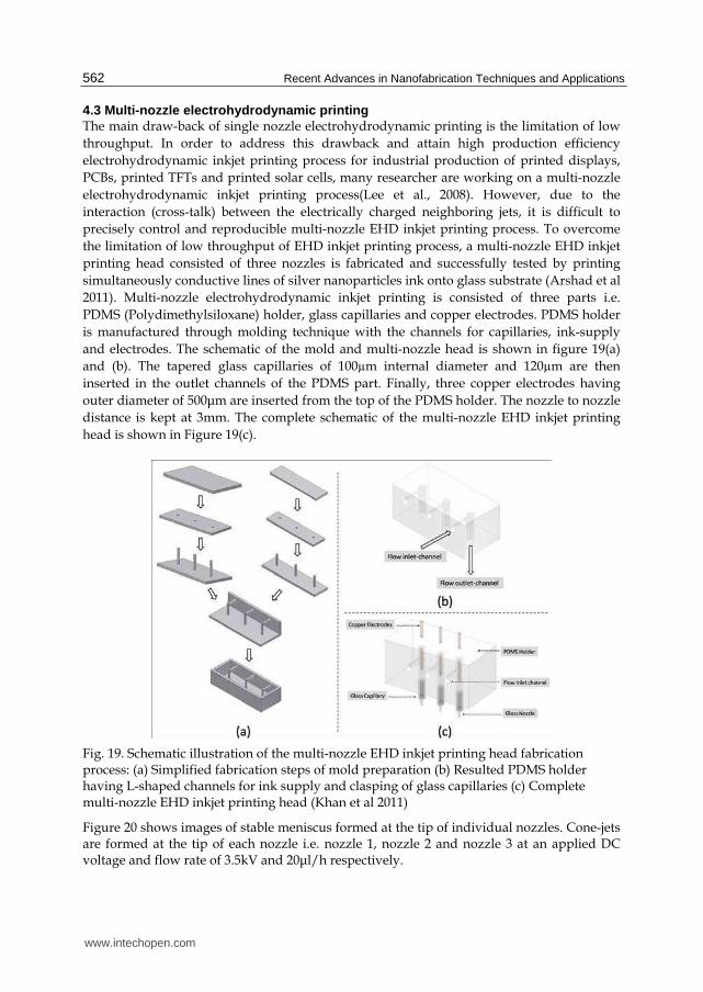
4.3 Multi-nozzle electrohydrodynamic printing The main draw-back of single nozzle electrohydrodynamic printing is the limitation of low
throughput. In order to address this drawback and attain high production efficiency
electrohydrodynamic inkjet printing process for industrial production of printed displays,
PCBs, printed TFTs and printed solar cells, many researcher are working on a multi-nozzle
electrohydrodynamic inkjet printing process(Lee et al., 2008). However, due to the
interaction (cross-talk) between the electrically charged neighboring jets, it is difficult to
precisely control and reproducible multi-nozzle EHD inkjet printing process. To overcome
the limitation of low throughput of EHD inkjet printing process, a multi-nozzle EHD inkjet
printing head consisted of three nozzles is fabricated and successfully tested by printing
simultaneously conductive lines of silver nanoparticles ink onto glass substrate (Arshad et al
2011). Multi-nozzle electrohydrodynamic inkjet printing is consisted of three parts i.e.
PDMS (Polydimethylsiloxane) holder, glass capillaries and copper electrodes. PDMS holder
is manufactured through molding technique with the channels for capillaries, ink-supply
and electrodes. The schematic of the mold and multi-nozzle head is shown in figure 19(a)
and (b). The tapered glass capillaries of 100µm internal diameter and 120µm are then
inserted in the outlet channels of the PDMS part. Finally, three copper electrodes having
outer diameter of 500μm are inserted from the top of the PDMS holder. The nozzle to nozzle
distance is kept at 3mm. The complete schematic of the multi-nozzle EHD inkjet printing
head is shown in Figure 19(c).
Fig. 19. Schematic illustration of the multi-nozzle EHD inkjet printing head fabrication process: (a) Simplified fabrication steps of mold preparation (b) Resulted PDMS holder having L-shaped channels for ink supply and clasping of glass capillaries (c) Complete multi-nozzle EHD inkjet printing head (Khan et al 2011)
Figure 20 shows images of stable meniscus formed at the tip of individual nozzles. Cone-jets are formed at the tip of each nozzle i.e. nozzle 1, nozzle 2 and nozzle 3 at an applied DC voltage and flow rate of 3.5kV and 20μl/h respectively.
www.intechopen.com

Electrohydrodynamic Inkjet – Micro Pattern Fabrication for Printed Electronics Applications
563
Fig. 20. Photographs of axisymmetric cone-jet established at the nozzles tips of multi-nozzle electrohydrodynamic inkjet printing head (Khan et al 2011)
Printing is performed by applying a DC voltage of 3.5kV and flow rate of 20μl/h to each
nozzle. The nozzles to substrate distance is set as 300μm while substrate speed is kept
constant at 10mm/sec. Figure 21 shows the high zoom static camera and optical microscope
image of continuous silver tracks simultaneously printed by three nozzles on glass substrate
without any defects such as bulges or coffee-ring effects. The average line width of the
printed lines is 140μm.
Fig. 21. Camera and optical microscope image of continuous silver patterns printed on glass substrate by multi-nozzle printing at an applied voltage of 3.5 kV and flow rate of 20μlh (Khan et al 2011)
www.intechopen.com

Recent Advances in Nanofabrication Techniques and Applications
564
Moreover, the SEM images of a typical printed line as shown in figure 22 also illustrates that nanoparticles are three-dimensionally interconnected with each other, which favorably affect the electrical conductivity.
Fig. 22. SEM image of continuous silver pattern deposited by multi-nozzle electrohydrodynamic inkjet printing (Khan et al 2011)
4.4 Thin film deposition The main benefit of the electrohydrodynamic atomization in cone-jet mode also known as electrospray deposition can be used for thin film deposition for functional materials on different substrates. The same experiment setup for printing is applicable for the thin film deposition through electrospray. In electrospray mode, the nozzle to substrate distance is larger than the patterning setup; this allows the jet to disintegrate into small monodisperse droplets of equal size due to the repulsive forces in the droplets carrying the charges. These mondisperse droplets landed on the substrate and generate the uniform thin layer of that material. The thickness and area of the layer depends on the flow-rate, distance between nozzle and substrate, and also the time of the spray. For thin film deposition of CIS (Copper-Indium di-Selenide) through electrospray deposition is performed by using 430µm internal diameter metallic nozzle (Muhammad et al., 2010). Initially the operating envelop for stable cone-jet is investigated for the ink containing CIS nanoparticles. The operating envelop for CIS ink along with different electrohydrodynamic modes is shown in figure 23. For spray purpose higher value of applied voltage is selected. Different experiments are performed by changing the flow rate and also the distance between nozzle and substrate distance. The quality and thickness of deposition of thin layers using ESD depends upon three main factors i.e. distance from nozzle to substrate, spraying time or substrate speed and the flow rate. Therefore as less is the distance between the nozzle and the substrate, higher will be the layer quality and also the layer thickness will be on the higher side and vice versa. Similarly as much is the spraying time, or as less is the substrate speed in this case, the layer quality will be on the higher side, however concerns will be on the thickness of the layer which can negatively affect the device efficiency. Figures 24 present the layer morphology obtained by SEM at a flow rate of 150µl/h and varying nozzle to substrate distances with substrate speed of
www.intechopen.com

Electrohydrodynamic Inkjet – Micro Pattern Fabrication for Printed Electronics Applications
565
0.5mm/s. As clear from the figures, the best layer quality is achieved at a nozzle to substrate distances of 6 mm and 8 mm the dense layers is produced and particles are completely intact and no pores or islands are visible as in the case of nozzle to substrate distances of 13mm the layer is porous and contain voids. These pores will case defect in the functionality of the deposited layer.
Fig. 23. Operating envelope for the CIS ink, showing different modes (Muhammad et al., 2010)
Fig. 24. FE-SEM micrographs of the deposited layer at stand-off distance of a. 6 mm, b. 8 mm, c. 10 mm, d. 13 mm, at substrate speed of 0.5 mm/s and flow rate of 150 ml/h (Muhammad et al., 2010)
5. Conclusions
Electrohydrodynamic inkjet printing is relatively new but very power tool and process for the direct patterning of the functional materials on substrate. Electrohydrodynamic inkjet
www.intechopen.com

Recent Advances in Nanofabrication Techniques and Applications
566
printing can be used in continuous mode as well as drop-on-demand mode. The main benefit of the electrohydrodynamic inkjet printing is generation of pattern smaller than the nozzle size, because the printing is performed by pulling the liquid rather than pushing of the liquid, which is limitation in other inkjet technology such as thermal and piezoelectric printing. The advantage of electrohydrodynamic printing over conventional printing is high resolution can be obtained. The other advantage of this direct patterning method is the flexibility in the process in terms of material to be used as well as patterns can be made on different kinds of substrate. In continuous mode the patterning is performed by achieving through thing continuous jet in the stable cone-jet mode, however the thin is difficult to stabilize due to electric field. The drop-on-demand mode can be used as alternative to continuous electrohydrodynamic printing. In drop-on-demand the stable cone-jet is achieved for shorter period of time by applying the pulse voltage. Single nozzle electrohydrodynamic printing has low throughput, in order to increase the efficiency multi-nozzle printing can be performed as reported. The other advantage of electrohydrodynamic printing is thin film deposition in electrospray mode. Thin films can be deposited on the surface of different substrate without changing the experimental setup. This combination of both the technologies (patterning and thin film deposition) can help in fabrication of the electronic devices such as TFT, OLED or Solar Cells etc. through single technology.
6. Challenges and future trends
There is lot of research is being performed in the field of the electrohydrodynamic printing by patterning the functional materials even in submicron level (Schirmer et al. 2010). However the functional materials meeting these requirements are a challenge, which can be used for the patterning purpose. The inks containing these functional materials impact the morphology, adhesion, chemical and environmental stability, these factors affect the performance. In addition to this the material used in direct patterning technologies has drawbacks in functional performance such as ion mobility, on-off voltage, threshold voltage and off current. Many researchers are working in the field of chemical and material technologies to overcome these limitations, by introducing the different materials that can be used for fabrication of devices through direct fabrication technology. Inorganic material such as carbon nanotube (single-wall and multi-wall) and metal nanoparticles (silver, gold and copper) based inks and pastes are commercially available for the direct patterning applications. Recently there researches are also working on the organic materials that can be used as the insulation material for electronic devices and also conductive organic material such as PEDOT, which can used for the fabrication of the conductive tracks. Recently composite polymers have received interests in the field of direct patterning material due to improvement in mechanical, thermal, optical and conductive properties. But the major drawback is still the performance of devices fabricated through the direct patterning technology as compared to conventional electronic. In electrohydrodynamic inkjet printing, for large area manufacturing the design of multi-nozzle printing head is another bottle neck due to interfering of electric field between nozzles. The miniaturization of the nozzles dimensions cause problems in obtaining the symmetric and stable cone-jet for printing. Other limitation is the fabrication of such small size nozzles. To optimize the performance of small nozzles, the physics and chemistry of the nozzle has to optimize to ensure the printability of different functional materials, with damaging the nozzles. When using the micron size nozzle, the issue of the clogging arises
www.intechopen.com

Electrohydrodynamic Inkjet – Micro Pattern Fabrication for Printed Electronics Applications
567
due to accumulation of the nanoparticles on the nozzle opening and cause blocking, which affects the performance of the printing. For micron size nozzle special inks are required from which printing can be performed. In general, electrohydrodynamic inkjet printing is powerful tools for direct patterning of the functional materials and can be used for high resolution printing. Developing this technology will allow exploring the potential application of electrohydrodynamic printing in high resolution fabrication of electronic devices and appear to be promising direction for the future.
7. Acknowledgement
This work was supported by the National Research Foundation of Korea (NRF) grant funded by the Korea government (MEST) (No.2010-0026163).
8. References
Pique, Alberto. & Chrisey, D. B. (2001). Direct-Write Technologies for Rapid Prototyping: Application to Sensors, Electronics, and Passivation Coatings, ISBN 978-0121742317, San Diego, USA
Gamota D., Brazis. P., Kalyansundaram, K. & Zhang, J. (2004). Printed Organic and Molecular Electronics. ISBN 1-4020-7707-6, Massachusetts, USA
Gans, B. J., Duineveld, P. C. & Schubert, U. S. (2004). Inkjet printing of polymers: State of the art and future development. Advanced Materials, 16, 203–213.
Lee, E., R. (2003). Microdrop Generation. ISBN 0-8493-1559-X, Florida USA Yang, L., Rida, A., Vyas, R. & Tentzeris,M. M. (2007). RFID Tag and RF Structures on a Paper
substrate Using Inkjet-Printing Technology. IEEE Transactions on Microwave Theory and techniques, vol. 55, no. 12
Jung, J., Kim, D., Lim, J., Lee, C. & Yoon, S. C. (2010). Highly Efficient Inkjet-Printed Organic Photovoltaic Cells. Japanese Journal of Applied Physics, 49, 5, 05EB03-05EB03-5
Arias, A. C., Ready, S. E., Lujan, R., Wong, W. S., Paul, K. E., Salleo, A., Chabinyc, M. L., Apte, R. & Street R. A. (2004). All jet-Printed Polymer Thin-Film Transistor Active-Matrix Backplanes. Applied Physics Letters, 85, 15, 3304-3306.
Goldmann, T., Gonzalez, J. S. (2000), DNA-Printing: Utilization of a Standard Inkjet Printer for the Transfer of Nucleic Acids to Solid Supports. Journal of Biochemical and Biophysical Methods, 42, 105-110.
Le, H. P. (1998). Progress and Trends in Ink-jet Printing Technology. The Journal of Imaging Science and Technology, 42, 1, 49-62
Park, J.U., Hardy, M., Kang, S.U. , Barton, K., Adair, K., Mukhopadhyay, D.K., Lee, C.Y., Strano, M. S., Alleyne A. G., Georgiadis, J. G., Ferreira, P. M. & Rogers, J. A. (2007). High-Resolution Electrohydrodynamic Jet Printing. Nature Materials, 6, 782-789
Hartman, R. P. A. (1998). Electrohydrodynamic Atomization in the Cone-jet Mode from Physical Modeling to Powder Production. PhD Thesis, TU Delft
Wang, K., Paine, M. D. & Stark, J. P. W. (2009). Fully Voltage-Controlled Electrohydrodynamic Jet Printing of Conductive Silver Tracks with a Sub-100µm Linewidth. Journal of Applied Physics, 106, 024907
Jaworek, A., (2007). Micro- and Nanoparticle Production by Electrospraying. Powder Technology, 176, 18–35
www.intechopen.com

Recent Advances in Nanofabrication Techniques and Applications
568
Park, J.U., Lee, H. L., Paik, U., Lu, L., & Rogers, J. A. (2008). Nanoscale Patterns of Oligonucleotides Formed by Electrohydrodynamic Jet Printing with Applications in Biosensing and Nanomaterials Assembly. Nano Letters, 8 (12), 4210-4216
Griss, P., Melin, J., Sjodahl, J., Roeraade, J., Stemme, G., (2002). Development of Micromachine Hollow Tips for Protein Analysis Based on Nanoelectrospray Ionization Mass Spectrometry. Journal Micromechanics and Microengineering, 12, 682–687
Poon, H. F. (2202). Electrohydrodynamic Printing. PhD thesis, Princeton University Cloupeau, M. & Foch B. P., (1994). Electrohydrodynamic Spraying Functioning Modes: A Critical
Review. Journal of Aerosol Science, 24 (6), 1021-1036 Hohman, M. M., Shin, M. Rutledge, G. & Brenner, M. P. (2001). Electrospinning and electrically
forced jets. I. Stability theory. Physics of Fluid, 13 (8), 2201-2220 Chen, C. H., Kelder, E. M., Van-Der-Put J.J.M. & Schoonman, J. (1996). Morphology Control of
Thin LiCoO2 Films Fabricated Using the Electrostatic Spray Deposition (ESD) technique. Journal of Materials Chemistry, 6, 765-771
Stachewicz U., Yurteri C.U., Marijnissen J.C.M., & Dijksman, J.F., (2009). Stability Regime of Pulse Frequency for Single Event Electrospraying. Applied Physics Letters 95, 224105
Li, J.L., & Zhang, P., (2009). Formation and Droplet Size of EHD Drippings Induced by Superimposing an Electric Pulse to Background Voltage. Journal of Electrostatic, 67, 562-567
Kim, J. H., Oh, H. C., & Kim, S. S. (2008). Electrohydrodynamic Drop-on-Demand Patterning in Pulsed Cone-Jet Mode at Various Frequencies. Journal of Aerosol Science, 39, 819-825
Rahman, K., Khan, A., Nam, N. M., Choi, K. H. & Kim D. S. (2011). Study of Drop-on-Demand Printing Through Multi-step Pulse Voltage. International Journal of Precision Engineering and Manufacturing, 12 (4)
Kim D. S., Khan, A., Rahman,, K., Khan, S., Kim, H. C. & Choi, K. H. (2010). Drop-on-Demand Direct Printing of Colloidal Copper Nanoparticles by Electrohydrodynamic Atomization. Materials and Manufacturing Processes (doi: 10.1080/10426914.2011.551956)
Lee J.S., Kim S.Y., Kim Y.J., Park J., Kim Y., Hawng. J., & Kim Y.J. (2008). Design and Evaluation of a Silicon Based Multi-Nozzle for Addressable Jetting Using a Controlled Flow Rate in Electrohydrodynamic Jet Printing. Applied Physics Letter, 93, 243114
Khan A., Rahman K., Hyun M.T., Kim D.S., & Choi K.H. (2011). Multi-Nozzle Electrohydrodynamic Inkjet Printing of Silver Colloidal Solution for the Fabrication of Electrically Functional Microstructure. Applied Physics A (doi:10.1007/s00339-011-6386-0)
Muhammad N. M., Sundharam, S., Dang H. W., Lee, A., Ryud B. H. & Choi K. H. (2010). CIS Layer deposition through electrospray process for solar cell fabrication. Current Applied Physics, 11 (1), S68-S75
Niklas C. Schirmer, N. C., Kullmann, C., Schmid, M. S., Burg, B. R., Schwamb, T., & Poulikakos D. (2010). On Ejecting Colloids Against Capillarity from Submicrometer Openings: On-Demand Dielectrophoretic Nanoprinting. Advanced Materials, 22, 4701-4705
www.intechopen.com

Recent Advances in Nanofabrication Techniques and ApplicationsEdited by Prof. Bo Cui
ISBN 978-953-307-602-7Hard cover, 614 pagesPublisher InTechPublished online 02, December, 2011Published in print edition December, 2011
InTech EuropeUniversity Campus STeP Ri Slavka Krautzeka 83/A 51000 Rijeka, Croatia Phone: +385 (51) 770 447 Fax: +385 (51) 686 166www.intechopen.com
InTech ChinaUnit 405, Office Block, Hotel Equatorial Shanghai No.65, Yan An Road (West), Shanghai, 200040, China
Phone: +86-21-62489820 Fax: +86-21-62489821
Nanotechnology has experienced a rapid growth in the past decade, largely owing to the rapid advances innanofabrication techniques employed to fabricate nano-devices. Nanofabrication can be divided into twocategories: "bottom up" approach using chemical synthesis or self assembly, and "top down" approach usingnanolithography, thin film deposition and etching techniques. Both topics are covered, though with a focus onthe second category. This book contains twenty nine chapters and aims to provide the fundamentals andrecent advances of nanofabrication techniques, as well as its device applications. Most chapters focus on in-depth studies of a particular research field, and are thus targeted for researchers, though some chapters focuson the basics of lithographic techniques accessible for upper year undergraduate students. Divided into fiveparts, this book covers electron beam, focused ion beam, nanoimprint, deep and extreme UV, X-ray, scanningprobe, interference, two-photon, and nanosphere lithography.
How to referenceIn order to correctly reference this scholarly work, feel free to copy and paste the following:
Kyung-Hyun Choi, Khalid Rahman, Nauman Malik Muhammad, Arshad Khan, Ki-Rin Kwon, Yang-Hoi Doh andHyung-Chan Kim (2011). Electrohydrodynamic Inkjet – Micro Pattern Fabrication for Printed ElectronicsApplications, Recent Advances in Nanofabrication Techniques and Applications, Prof. Bo Cui (Ed.), ISBN: 978-953-307-602-7, InTech, Available from: http://www.intechopen.com/books/recent-advances-in-nanofabrication-techniques-and-applications/electrohydrodynamic-inkjet-micro-pattern-fabrication-for-printed-electronics-applications

© 2011 The Author(s). Licensee IntechOpen. This is an open access articledistributed under the terms of the Creative Commons Attribution 3.0License, which permits unrestricted use, distribution, and reproduction inany medium, provided the original work is properly cited.