electrochemical supercapacitors - defence...
TRANSCRIPT

Defence R&D Canada – Atlantic
Electrochemical SupercapacitorsFinal Report
Michael S. FreundGraeme SuppesUniversity of Manitoba
University of ManitobaDepartment of ChemistryWinnipeg, Manitoba R3T 2N2
Project Manager: Michael S. Freund, 204-474-8772
Contract Number: W7707-063349
Contract Scientific Authority: Colin G. Cameron, 902-427-1367
The scientific or technical validity of this Contract Report is entirely the responsibility of the contractorand the contents do not necessarily have the approval or endorsement of Defence R&D Canada.
Contract Report
DRDC Atlantic CR 2009-233
November 2009
Copy No. _____
Defence Research andDevelopment Canada
Recherche et développementpour la défense Canada

This page intentionally left blank.

Electrochemical SupercapacitorsFinal Report
Michael S. Freund
Graeme Suppes
University of Manitoba
Prepared by:
University of Manitoba
Department of Chemistry
Winnipeg MB R3T 2N2
Project Manager: Michael S. Freund 204-474-8772
Contract Number: W7707-063349
Contract Scientific Authority: Colin G. Cameron 902-427-1367
The scientific or technical validity of this Contract Report is entirely the responsibility of the contractor
and the contents do not necessarily have the approval or endorsement of Defence R&D Canada.
Defence R&D Canada – Atlantic
Contract Report
DRDC Atlantic CR 2009-233
November 2009

Approved by
Leon Cheng
Section Head / Dockyard Laboratory (Atlantic)
Approved for release by
Calvin Hyatt
Chair / Document Review Panel
c© Her Majesty the Queen in Right of Canada as represented by the Minister of National
Defence, 2009
c© Sa Majeste la Reine (en droit du Canada), telle que representee par le ministre de la
Defense nationale, 2009
Original signed by Leon Cheng
Original signed by Ron Kuwahara for

Abstract
This report summarizes results from the final year of this three-year project in developing
supercapacitor electrode materials based on conducting polymers. Polypyrrole, formed by
the controlled growth polymerization method, was combined with carbon nanotubes in an
attempt to improve the electronic and ionic conductivity of polymer films. Single-walled
nanotubes were successfully dispersed in water and tetrahydrofuran using phosphomolyb-
dic acid. However, polypyrrole films containing single walled nanotubes did not show any
improved performance.
Poly(3,4-ethylenedioxythiophene) (PEDOT) films were grown electrochemically on car-
bon paper using phosphotungstic acid (PTA) as a dopant. The resulting PEDOT/PTA films
were used as negative electrodes in an asymmetric supercapacitor cells, resulting in im-
proved power and energy density compared to symmetric designs.
Resume
Ce rapport resume les resultats de la troisieme et derniere annee du projet qui visait a
developper de nouveaux materiaux a base de polymere conducteur pour des electrodes de
supercondensateur. Du polypyrrole, forme selon la methode de polymerisation controlee, a
ete combine avec des nanotubes de carbone afin d’ameliorer la conductibilite electronique
et ionique des films polymeriques. Des nanotubes monoparoi ont ete disperses avec succes
dans l’eau et dans le tetrahydrofuran par l’action de l’acide phosphomolybdique. Cepen-
dant, les films de polypyrrole contenant des nanotubes n’ont demontre aucune propriete
amelioree.
Des films de Poly(3,4-ethylenedioxythiofene) ont ete deposes sur du tissu carbone a l’aide
de l’acide phosphotungstique comme dopant. En tant qu’electrode negative d’un supercon-
densateur asymetrique, ce materiau a realise une importante amelioration de puissance et
d’energie par rapport aux supercondensateurs symetriques.
DRDC Atlantic CR 2009-233 i

This page intentionally left blank.
ii DRDC Atlantic CR 2009-233

Executive summary
Electrochemical Supercapacitors: Final Report
Michael S. Freund, Graeme Suppes; DRDC Atlantic CR 2009-233; Defence R&D
Canada – Atlantic; November 2009.
Background: This Technology Investment Fund (TIF) program aimed to develop im-
proved supercapacitor technology through the design of better electrode materials. This
will ultimately yield devices with elevated power and energy densities and/or performance
custom tailored to the needs of the Canadian military. The present work focused on (i)
improving the electronic and ionic conductivity of conducting polymers and (ii) widening
the potential window available to store charge in a supercapacitor.
Principal Results: The research conducted by M.S. Freund at the University of Manitoba
revealed two key results: (i) single walled nanotubes, purified and dispersed, do not im-
prove the capacitive performance of conducting polymer films, and (ii) the electropolymer-
ization of poly 3,4-ethylenedioxythiophene (PEDOT) using phosphotungstic acid (PTA)
results in stable films. These films were used with polypyrrole/phosphomolybdic acid
(PPy/PMA) films in asymmetric supercapacitors that showed improved performance over
similar symmetric devices.
The report concludes with a summary of program highlights.
Significance: Asymmetric electrodes permit the operation of the capacitor over a wider
voltage range while maintaining the desirable charge storage capacity of the polyoxometa-
late/conducting polymer composites. A wider voltage window is desirable, since the energy
content of a supercapacitor device increases as the square of its operating voltage.
Future Work: This report marks the conclusion of this TIF program. Follow-on programs
are in place to construct self-contained proof-of-concept supercapacitor devices using the
best materials arising from this program. Other work will see the production of militarily-
relevant demonstration technology to illustrate the application of supercapacitors in pulsed
power devices, and optimization of low-temperature performance.
DRDC Atlantic CR 2009-233 iii

Sommaire
Electrochemical Supercapacitors: Final Report
Michael S. Freund, Graeme Suppes ; DRDC Atlantic CR 2009-233 ; R & D pour la
defense Canada – Atlantique ; novembre 2009.
Contexte : Ce programme de Fonds d’Investissement en Technologie (FIT) avait pour but
d’ameliorer la technologie de supercapacitors en developpant de nouveaux materiaux pour
les electrodes. Ceci produira finalement des dispositifs qui pourront fournir des quantites
augmentes de puissance et d’energie, ou qui serront adaptes aux besoins de l’armee cana-
dienne. Les efforts decrits dans ce rapport visaient a (i) augmenter la conductibilite elec-
tronique et ionique des polymeres conducteurs, et (ii) elargir les limites de tension dans
lesquelles le supercondensateur conserve l’energie.
Resultats principaux : Les recherches menees par M.S. Freund (University of Manitoba)
ont devoile deux resultats cles : (i) les nanotubes de carbone monoparoi, purifies et dis-
perses, n’augmentent pas la capacite des films en polymere conducteur, et (ii) l’electro-
polymerisation de 3,4-ethylenedioxythiofene (PEDOT) avec de l’acide phosphotungstique
(PTA) produit des films stables. On a fabrique des supercondensateurs en se servant des
films de PEDOT/PTA et de polypyrrole plus de l’acide phosphomolybdique (PPy/PMA),
et ces supercondensateurs asymetriques ont realise une performance amelioree par rapport
aux supercondensateurs symetriques.
Le rapport se termine avec un resume des faits saillants du programme.
Portee : Des electrodes asymetriques permettent l’operation du supercondensateur dans
une gamme de tension plus etendue tout en soutenant la capacite energetique des com-
posites de polyoxometalate / polymere conducteur. Une gamme de tension etendue est
desirable parce que le niveau d’energie stocke par un condensateur augmente comme le
carre de la tension.
Recherches futures : Ce rapport marque la conclusion du programme TIF. Un autre pro-
gramme est deja mis en place pour demontrer la faisabilite d’un supercondensateur inde-
pendant construit a partir des materiaux provenant du programme TIF. On tentera aussi de
realiser des equipements militaires alimentes de supercondensateurs pour demontrer l’uti-
lisation de cette technologie en tant que fournisseur de puissance pulsee. Finalement, on
visera a ameliorer la performance des supercondensateurs aux temperatures basses.
iv DRDC Atlantic CR 2009-233

Table of contents
Abstract . . . . . . . . . . . . . . . . . . . . . . . . . . . . . . . . . . . . . . . . . i
Resume . . . . . . . . . . . . . . . . . . . . . . . . . . . . . . . . . . . . . . . . . i
Executive summary . . . . . . . . . . . . . . . . . . . . . . . . . . . . . . . . . . . iii
Sommaire . . . . . . . . . . . . . . . . . . . . . . . . . . . . . . . . . . . . . . . . iv
Table of contents . . . . . . . . . . . . . . . . . . . . . . . . . . . . . . . . . . . . v
List of figures . . . . . . . . . . . . . . . . . . . . . . . . . . . . . . . . . . . . . . vii
List of tables . . . . . . . . . . . . . . . . . . . . . . . . . . . . . . . . . . . . . . . x
1 Introduction . . . . . . . . . . . . . . . . . . . . . . . . . . . . . . . . . . . . . 1
2 Experimental . . . . . . . . . . . . . . . . . . . . . . . . . . . . . . . . . . . . 2
2.1 Materials and chemicals . . . . . . . . . . . . . . . . . . . . . . . . . . . 2
2.2 Characterization . . . . . . . . . . . . . . . . . . . . . . . . . . . . . . . 2
2.2.1 Electrochemistry . . . . . . . . . . . . . . . . . . . . . . . . . . 2
2.2.2 Morphology . . . . . . . . . . . . . . . . . . . . . . . . . . . . 3
2.2.3 Fourier transform infrared – attenuated total reflection
(FTIR-ATR) spectroscopy. . . . . . . . . . . . . . . . . . . . . . 3
3 Phosphomolybdic acid coated single walled carbon nanotubes . . . . . . . . . . 3
3.1 Preparation . . . . . . . . . . . . . . . . . . . . . . . . . . . . . . . . . . 3
3.2 FTIR-ATR spectroscopic characterization of filtered carbon nanotubes . . 4
3.3 Electrochemical characterization of PMA-coated carbon nanotubes . . . . 5
3.4 PPy/PMA films containing single walled carbon nanotubes . . . . . . . . 7
4 PEDOT/PTA films for a negative electrode . . . . . . . . . . . . . . . . . . . . . 8
4.1 PEDOT/PTA films grown on glassy carbon electrodes . . . . . . . . . . . 8
4.2 PEDOT-PTA films grown on carbon paper . . . . . . . . . . . . . . . . . 10
4.3 Morphology of PEDOT/PTA films on carbon paper . . . . . . . . . . . . 11
DRDC Atlantic CR 2009-233 v

5 Asymmetric supercapacitor cell . . . . . . . . . . . . . . . . . . . . . . . . . . . 14
5.1 Finding optimum cell potential window . . . . . . . . . . . . . . . . . . 14
5.2 Charge-discharge of asymmetric supercapacitors . . . . . . . . . . . . . . 16
5.2.1 Cell performance . . . . . . . . . . . . . . . . . . . . . . . . . . 16
5.2.2 Cell stability . . . . . . . . . . . . . . . . . . . . . . . . . . . . 19
6 Conclusion . . . . . . . . . . . . . . . . . . . . . . . . . . . . . . . . . . . . . 21
7 Program Highlights . . . . . . . . . . . . . . . . . . . . . . . . . . . . . . . . . 22
7.1 Introduction . . . . . . . . . . . . . . . . . . . . . . . . . . . . . . . . . 22
7.2 Highlights . . . . . . . . . . . . . . . . . . . . . . . . . . . . . . . . . . 22
References . . . . . . . . . . . . . . . . . . . . . . . . . . . . . . . . . . . . . . . . 28
Symbols and abbreviations . . . . . . . . . . . . . . . . . . . . . . . . . . . . . . . 32
Distribution list . . . . . . . . . . . . . . . . . . . . . . . . . . . . . . . . . . . . . 33
vi DRDC Atlantic CR 2009-233

List of figures
Figure 1: Swagelok cell for 2 electrode capacitance measurements. . . . . . . . . . 3
Figure 2: Schematic diagram of the cell used in this work. The active material
(polymer/POM) was coated onto carbon paper and separated by a
Nafion membrane heated in H2SO4. . . . . . . . . . . . . . . . . . . . . 4
Figure 3: Steps to disperse and collect SWNT in an aqueous solution of PMA . . . 5
Figure 4: FTIR-ATR of (A) unmodified SWNTs, (B) PMA, and (C) SWNTs
dispersed in PMA and filtered onto 200 nm (pore size) nylon membranes. 6
Figure 5: Cyclic voltammetry of a blank gold-coated nylon membrane (“Gold”),
unmodified SWNTs (“SWNT”), and SWNTs dispersed in PMA
(“SWNT-PMA”). All CVs were recorded in 0.5 M H2SO4 using
approximately 1 cm2 of the filter membrane as a working electrode, an
Ag/AgCl reference electrode, a platinum wire counter electrode, and at
a scan rate of 100 mV/s. . . . . . . . . . . . . . . . . . . . . . . . . . . 6
Figure 6: Scanning electron microscope images of a PPy/PMA/SWNT film spin
coated onto a glass slide at 2000 RPM for 10 seconds. . . . . . . . . . . 7
Figure 7: Cyclic voltammetry of PPy/PMA films with and without SWNTs, spin
coated onto glassy carbon and cycled at (a) 100 mV/s and (b) 1000
mV/s in 0.5 M H2SO4. . . . . . . . . . . . . . . . . . . . . . . . . . . . 8
Figure 8: Cyclic voltammetry of 50 mM PTA in 0.5 M H2SO4 cycled at
100 mV/s using a glassy carbon working electrode, a Ag/AgCl
reference electrode, and a platinum wire counter electrode. . . . . . . . . 9
Figure 9: Cyclic voltammetry of a glassy carbon electrode in 10 mM EDOT and
50 mM PTA for 10 cycles at 100 mV/s. . . . . . . . . . . . . . . . . . . 9
Figure 10: Cyclic voltammetry of films of PEDOT-PTA and PEDOT-TBAP on
glassy carbon disc electrodes in 0.5 M H2SO4 cycled at 100 mV/s . . . . 10
Figure 11: Growth of PEDOT/PTA films by cyclic voltammetry on carbon paper
in an acetonitrile solution of 10 mM EDOT and 10 mM PTA. The scan
rate was 10 mV/s for 5 cycles. . . . . . . . . . . . . . . . . . . . . . . . 11
DRDC Atlantic CR 2009-233 vii

Figure 12: PEDOT/PTA on carbon paper cycled in 0.5 M H2SO4 at 100 mV/s.
After electropolymerization and drying, a 5% solution of Nafion in
methanol was applied to the coated carbon paper and left to dry in air
overnight. Rcomp = 2−3 Ω . . . . . . . . . . . . . . . . . . . . . . . . . 12
Figure 13: Uncoated carbon paper . . . . . . . . . . . . . . . . . . . . . . . . . . . 12
Figure 14: PEDOT/PTA grown electrochemically on carbon paper at 10 mV/s
between 0.5 V and 1.3 V vs. Ag/AgNO3 for 5 cycles. . . . . . . . . . . . 13
Figure 15: PPy/PMA grown chemically on carbon paper from a solution of
125 mM Py and 62.5 mM PMA (in THF), dried and rinsed (with
methanol) between layers. . . . . . . . . . . . . . . . . . . . . . . . . . 13
Figure 16: Uncoated carbon paper cycled at 100 mV/s in aqueous H2SO4, showing
solvent breakdown at the potential limits. . . . . . . . . . . . . . . . . . 14
Figure 17: (a) The degradation of PPy/PMA by exposure to elevated potentials,
and (b) the result of such damage on the voltammetric response of the
film. . . . . . . . . . . . . . . . . . . . . . . . . . . . . . . . . . . . . 15
Figure 18: Overoxidation of PPy and PEDOT films in 0.5 M H2SO4. Both films
were grown electrochemically from a solution of 0.01 M monomer and
0.1 M tetrabutyl ammonium perchlorate in acetonitrile. Scan rate:
100 mV/s. . . . . . . . . . . . . . . . . . . . . . . . . . . . . . . . . . 15
Figure 19: PEDOT/PTA on a carbon paper disc (diameter 1.12 cm): (a) cycled in
0.5 M H2SO4 at ν = 100 mV/s vs. Ag/AgCl, and (b) the effect of
exposing the film to −1 V. Rcomp = 2−3 Ω . . . . . . . . . . . . . . . . 16
Figure 20: Superimposed 3-electrode voltammograms of PEDOT/PTA (black) and
PPy/PMA (red) at 100 mV/s in 0.5 M H2SO4. The voltammograms are
overlaid to show the range of a 1 V supercapacitor cycle when the
electrodes have been preset to 0 V vs. Ag/AgCl. Rcomp = 2−3 Ω . . . . 17
Figure 21: Asymmetric cell with a PPy/PMA positive electrode, a PEDOT/PTA
negative electrode, and a Nafion separator, cycled at 100 mV/s in 0.5 M
H2SO4. . . . . . . . . . . . . . . . . . . . . . . . . . . . . . . . . . . . 17
Figure 22: Charge-discharge characteristics of an asymmetric cell cycled through
1 V. . . . . . . . . . . . . . . . . . . . . . . . . . . . . . . . . . . . . . 18
viii DRDC Atlantic CR 2009-233
Figure 23: PPy/PMA carbon paper disc electrode before and after 200
charge-discharge cycles in a supercapacitor cell. The disc was initially
set to a potential of 0.2 V vs. Ag/AgCl in a 3 electrode cell.
Rcomp = 2−3 Ω . . . . . . . . . . . . . . . . . . . . . . . . . . . . . . . 19
Figure 24: CV of PPy/PMA and PEDOT/PTA in a 3-electrode cell before and after
200 charge-discharge cycles in a supercapacitor cell. . . . . . . . . . . . 20
Figure 25: Charge-discharge profiles at 1 mA of an asymmetric cell with both
electrodes initially set to 0 V vs. Ag/AgCl. . . . . . . . . . . . . . . . . 20
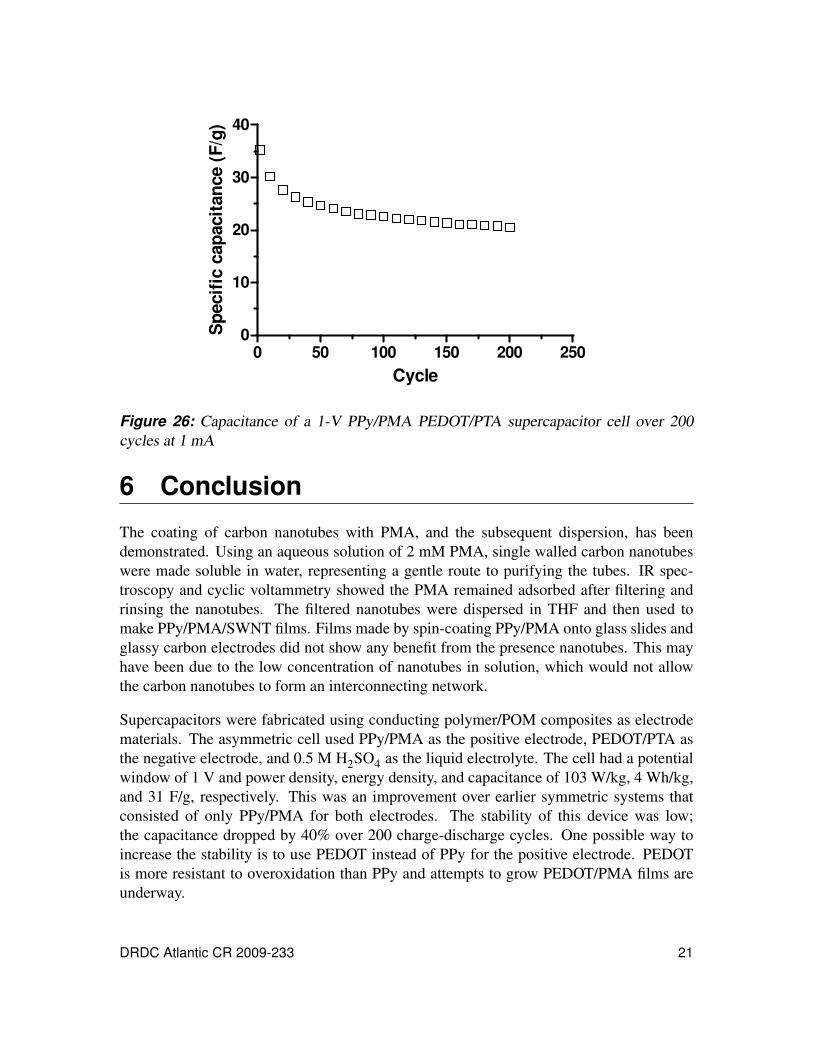
Figure 26: Capacitance of a 1-V PPy/PMA PEDOT/PTA supercapacitor cell over
200 cycles at 1 mA . . . . . . . . . . . . . . . . . . . . . . . . . . . . . 21
Figure 27: Scanning electron micrographs of PPy/PMA. Films were prepared
using 375 mM pyrrole and 1875 mM PMA in THF with (a) 5, (b) 10,
(c) 20, and (d) 40 mg/mL of porogen. . . . . . . . . . . . . . . . . . . . 23
Figure 28: Cyclic voltammograms of chemically prepared PPy/PMA film (a)
without and (b) with 2 mg/mL of porogen on a GC electrode in 0.5 M
H2SO4 at various scan rate (10 mV/s to 20 V/s). . . . . . . . . . . . . . 23
Figure 29: PPy/PMA grown chemically on carbon paper by depositing a solution
of 125 mM pyrrole and 62.5 mM PMA in THF onto carbon paper four
times, and was dried and rinsed in methanol between each deposition. . 24
Figure 30: Cyclic voltammetry of a multi-layer film of PPy/PMA cycled in 0.5 M
H2SO4 at a scan rate of 100 mV/s. The films were prepared by
depositing 4 layers of 125 mM Py and 62.5 mM PMA in THF, rinsing
in methanol and drying between each layer. Rcomp = 2−3 Ω . . . . . . . 25
Figure 31: PEDOT/PTA grown electrochemically on carbon paper. . . . . . . . . . 26
Figure 32: Superimposed 3-electrode voltammograms of PEDOT/PTA (black) and
PPy/PMA (red) at 100 mV/s in 0.5 M H2SO4. The CVs are overlaid to
show the range of a 1 V supercapacitor cycle when the electrodes have
been preset to 0 V vs. Ag/AgCl. Rcomp = 2−3 Ω . . . . . . . . . . . . . 26
Figure 33: Asymmetric cell with PPy/PMA as a positive electrode and
PEDOT/PTA as a negative electrode, cycled at 100 mV/s with a Nafion
membrane separator and 0.5 M H2SO4 electrolyte. . . . . . . . . . . . . 27
DRDC Atlantic CR 2009-233 ix

List of tables
Table 1: IR Band assignment for PMA . . . . . . . . . . . . . . . . . . . . . . . 5
Table 2: Energy density, power density, and specific capacitance of an
asymmetric cell cycled at various constant currents through a potential
window of 1 V. . . . . . . . . . . . . . . . . . . . . . . . . . . . . . . . 19
Table 3: Energy density, power density, and specific capacitance of an
asymmetric cell cycled at various constant currents through a potential
window of 1 V. . . . . . . . . . . . . . . . . . . . . . . . . . . . . . . . 25
x DRDC Atlantic CR 2009-233
1 Introduction
The interest in supercapacitors arises from applications that demand transient bursts of
power and/or for hybrid systems when coupled with a lower power source such as a
fuel cell [1]. High-surface-area carbons [2, 3], metal oxides [4, 5], and conducting poly-
mers [6,7] are examples of commonly researched supercapacitor electrode materials. These
materials provide higher energy density than conventional parallel-plate capacitors [8, 9].
Conducting polymers are particularly attractive due to the fast electrochemical switching
and the possibility of synthetic modification. A further advantage is that one may add elec-
troactive molecular clusters to form hybrid materials that offer improved stability, better
charge propagation dynamics, and enhanced storage capacity.
Conducting polymers generally exhibit high electrical conductivity, and it has been shown
that the conductivity can be improved by the addition of carbon nanotubes (CNTs), either
during the polymerization or afterwards [10, 11]. Prior to use, it is necessary to separate
carbon nanotube bundles, remove amorphous carbon, remove metal nanoparticle catalysts,
and introduce functional groups. Almost always, this procedure involves sonicating or re-
fluxing the carbon nanotubes in concentrated acid. This treatment with strong acid leads to
a breakdown of the nanotube walls and shortening of the tubes [12]. Fei et al. have demon-
strated that it is possible to disperse and coat carbon nanotubes with a polyoxometalate
(POM) [13]. By sonicating raw carbon nanotubes with a low concentration of phospho-
tungstic acid (PTA) they were able to disperse the nanotubes into water. The POM remains
absorbed along the nanotube walls after filtering. It is well known that POMs, such as
phosphomolybdic acid (PMA), adsorb spontaneously to carbon-containing materials such
as carbon powders and fibres [14, 15] and carbon nanotubes [16–20]. This could be very
useful from a power source point of view as these adsorbed species may form channels
of high ionic conductivity (the POMs) along channels of high electrical conductivity (the
CNTs). In addition, the presence of a conducting polymer could further enhance properties
by minimizing the contact resistance between carbon nanotubes [21–23]. PMA may be
used as an oxidant and dopant for growing conducting polymer films such as polypyrrole
(PPy) [24]; however, the PMA is most likely dispersed throughout the film and would not
be close enough to form any channels of ionic conductivity. Here, we use PMA to dis-
perse and coat single walled nanotubes (SWNTs) so that they may be incorporated into
conducting polymers.
In addition to improving the electrical and ionic conductivity of conducting polymer films,
there is also an interest in extending the potential window over which a conducting poly-
mer/POM supercapacitor device operates. Work has been done initially with PPy/PMA.
Symmetric devices, where both electrodes are PPy/PMA, have a potential window of only
about 0.5 V in an acidic electrolyte. This is because PMA displays irreversible electro-
chemical behaviour below −0.1 V (vs. Ag/AgCl) when cycled in H2SO4. Other conduct-
ing polymer/POM materials have been examined to extend the potential window, for ex-
DRDC Atlantic CR 2009-233 1
ample PTA which undergoes reversible redox reactions below 0 V in acid. While PTA has
been used as a dopant to electrochemically grow poly(3,4-ethylenedioxythiophene) (PE-
DOT) on glassy carbon and carbon paper, there are very few examples in the literature of
using PTA as a dopant for conducting polymers [25–29]. PTA remains trapped and elec-
troactive in polymer films and coated carbon paper discs which can be used as a negative
electrode in a 2 electrode cell. With the corresponding extension of the potential window,
an improvement in the energy and power density is gained over cells consisting of only
PPy/PMA [30, 31].
2 Experimental
2.1 Materials and chemicals
Phosphomolybdic acid, 3,4-ethylene dioxythiophene (EDOT), phosphotungstic acid hy-
drate, single walled carbon nanotubes, and tetrabutyl ammonium perchlorate were pur-
chased from Aldrich and used without further purification. Pyrrole (Py) was purchased
from Aldrich. It was distilled before use and stored at −20C. Acetonitrile (HPLC grade)
was purchased from Fisher and used without further purification. Type GNWP04700 Ny-
lon membranes (0.20 µm pore size) were purchased from Millipore and used to collect
dispersed nanotubes. Nafion membranes (NRE-211) were purchased from Ion Power,
Inc., and cut into discs of 1.12 cm diameter and used as a separator material. Before use,
the membranes were placed in 0.5 M H2SO4 and heated to 60–80C for 30 minutes, and
then left to cool to room temperature [32]. Carbon paper was purchased from Spectacarb
(2050A) and cut in to discs of 1.12 cm diameter for use as a working electrode. Before
use, the carbon paper discs were sonicated for 20 minutes in 30% H2O2, then acetone, and
rinsed in deionized (DI) water. Glassy carbon disc electrodes (3 mm diameter) were pur-
chased from CH Instruments. Before use, the glassy carbon electrodes were polished with
suspensions of different size alumina particles (1, 0.3, and 0.05 µm, in order) purchased
from Buehler. The 2-electrode cell consisted of a 1.27 cm (0.5 inch) diameter Swagelok
Teflon tube union that was bored out so that the diameter was constant along the inside the
tube (Figure 1).
2.2 Characterization2.2.1 Electrochemistry
All electrochemical experiments were preformed on a BAS 100A potentiostat worksta-
tion and a Solartron 1287 potentiostat with a Solartron 1255B frequency analyzer. All
3-electrode experiments were done using (i) a Ag/AgCl reference electrode for aqueous
solutions or a Ag/AgNO3 reference electrode for non-aqueous solutions, (ii) a platinum
foil or wire as a counter electrode, and (iii) either glassy carbon disc electrodes or car-
bon paper as the working electrode. In some of the 3-electrode experiments with coated
2 DRDC Atlantic CR 2009-233
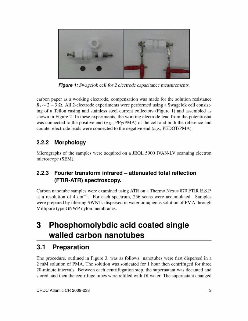
Figure 1: Swagelok cell for 2 electrode capacitance measurements.
carbon paper as a working electrode, compensation was made for the solution resistance
Rs ∼ 2−3 Ω. All 2-electrode experiments were performed using a Swagelok cell consist-
ing of a Teflon casing and stainless steel current collectors (Figure 1) and assembled as
shown in Figure 2. In these experiments, the working electrode lead from the potentiostat
was connected to the positive end (e.g., PPy/PMA) of the cell and both the reference and
counter electrode leads were connected to the negative end (e.g., PEDOT/PMA).
2.2.2 Morphology
Micrographs of the samples were acquired on a JEOL 5900 IVAN-LV scanning electron
microscope (SEM).
2.2.3 Fourier transform infrared – attenuated total reflection
(FTIR-ATR) spectroscopy.
Carbon nanotube samples were examined using ATR on a Thermo Nexus 870 FTIR E.S.P.
at a resolution of 4 cm−1. For each spectrum, 256 scans were accumulated. Samples
were prepared by filtering SWNTs dispersed in water or aqueous solution of PMA through
Millipore type GNWP nylon membranes.
3 Phosphomolybdic acid coated single
walled carbon nanotubes
3.1 Preparation
The procedure, outlined in Figure 3, was as follows: nanotubes were first dispersed in a
2 mM solution of PMA. The solution was sonicated for 1 hour then centrifuged for three
20-minute intervals. Between each centrifugation step, the supernatant was decanted and
stored, and then the centrifuge tubes were refilled with DI water. The supernatant changed
DRDC Atlantic CR 2009-233 3

Figure 2: Schematic diagram of the cell used in this work. The active material (poly-
mer/POM) was coated onto carbon paper and separated by a Nafion membrane heated in
H2SO4.
from black to transparent grey over the course of three runs. A fourth centrifugation yielded
a very clear supernatant so the process was deemed complete after three intervals. The
sediment was collected and re-dispersed in a 2 mM solution of PMA and the whole process
was repeated twice more. After sonicating in PMA for a third time the supernatant became
clear on the second centrifugation. All of the collected, dispersed nanotubes were filtered
through a 200 nm nylon membrane and rinsed with water until the filtrate became clear. The
membranes caked with nanotubes were dried overnight under vacuum at room temperature
before continuing with experiments. A 100 mL sample was found to contain 6.3±0.3 mg
of SWNTs.
The films were measured with a micrometer to be about 10 µm. Four-point probe measure-
ments were made on the dried films and the conductivity was calculated to be 3.44 S/cm
(average) which is lower than that reported by Adronov for unmodified SWNTs follow-
ing a similar method, 210± 40 S/cm for a 90 µm thick film on a Teflon membrane [33].
Nanotubes modified with polyfluorene and polyfluorene-co-thiophene had values of 34 and
52 S/cm, respectively, which implies that the low value obtained was due to adsorption of
large amounts of PMA to the surface of the nanotubes.
The nanotubes on the nylon membrane were then re-dispersed into water, THF, or acetoni-
trile. The nanotubes in water were well-dispersed and remained so beyond a week. In THF,
however, the nanotubes started to aggregate, but they could be completely dispersed with a
few seconds of sonication.
3.2 FTIR-ATR spectroscopic characterization of
filtered carbon nanotubes
Figure 4 presents IR spectra of unmodified CNTs, PMA, and CNTs modified with PMA.
The bands for PMA are listed in Table 1 and have been assigned previously [34–36]. The
PMA bands can clearly be seen in the spectrum of modified CNTs, indicating a strong
4 DRDC Atlantic CR 2009-233

Figure 3: Steps to disperse and collect SWNT in an aqueous solution of PMA
interaction without alteration of the structure of PMA. The peak at 935 cm−1 is due to the
nylon membrane.
3.3 Electrochemical characterization of PMA-coated
carbon nanotubes
The coated nanotubes were also examined by cyclic voltammetry in acid. A nylon mem-
brane, sputter coated with gold, was used to collect nanotubes by filtration. The membranes
were cut into pieces of approximately 1 cm2 and used as the working electrode. The cyclic
voltammograms (CVs) in Figure 5 show the two sets of peaks associated with PMA, con-
firming that it remained adsorbed and unchanged after filtering and washing.
Table 1: IR Band assignment for PMA [36]
Band Peak (cm−1)
ν1 Mo−O−Mo (edge) 760–800
ν2 Mo−O−Mo (corner) 840–910
ν3 Mo−−O (terminal) 960–1000
ν4 P−O 1060–1080
DRDC Atlantic CR 2009-233 5


-0.2 0.0 0.2 0.4 0.6 0.8-2
-1
0
1
2
3PPy/PMA/SWNT
PPy/PMA
Potential (V vs. Ag/AgCl)
Cu
rren
t (m
A)
-0.2 0.0 0.2 0.4 0.6 0.8-15
-10
-5
0
5
10
15PPy/PMA/SWNT
PPy/PMA
Potential (V vs. Ag/AgCl)
Cu
rren
t (m
A)
(a) (b)
Figure 7: Cyclic voltammetry of PPy/PMA films with and without SWNTs, spin coated
onto glassy carbon and cycled at (a) 100 mV/s and (b) 1000 mV/s in 0.5 M H2SO4.
4 PEDOT/PTA films for a negative electrode
4.1 PEDOT/PTA films grown on glassy carbon
electrodes
In a previous report [39], it was proposed that using PTA as a dopant could extend the
potential window in which a capacitor operates. The energy stored by a capacitor is pro-
portional to the square of the voltage, so maximizing this value would be desirable. Phos-
photungstic acid is a POM that has multiple redox reactions at potentials lower than those
of PMA, as indicated in Figure 8.
PEDOT was chosen as the conducting polymer for the negative electrode because it ought
to remain conductive in the potential window of interest [40, 41]. Phosphotungstic acid is
insufficiently oxidative to polymerize EDOT, so polymer films were prepared electrochem-
ically. The films were first prepared on glassy carbon disc electrodes using 10 mM EDOT
and 50 mM PTA in acetonitrile with a silver wire quasi-reference electrode (QRE) and
platinum wire counter electrode. The films were grown by cyclic voltammetry between 0
and 1.3 V (vs. Ag QRE) at 100 mV/s for ten cycles (Figure 9). Polymerization of the poly-
mer began at about 1 V vs. Ag QRE with a sharp increase in the current. This continued
until all of the monomer at the surface had been consumed, which was represented by a
peak at about 1.1 V vs. Ag QRE. Between 0 and 1 V, the current increased with each cycle,
indicating that the polymer was being deposited on the electrode surface.
The resulting films show the redox reactions associated with PTA in H2SO4 (Figure 10).
The peak separation is small, suggesting the PTA counter ion is present as a surface-bound
species. The control films were made under the same conditions with electrochemically-
inactive tetrabutyl ammonium perchlorate (TBAP) as the counter ion. Naturally, the three
PTA peaks are absent, but the residual current in the CVs does show that the PEDOT
remains electroactive in the potential window of interest.
8 DRDC Atlantic CR 2009-233

-1.0 -0.5 0.0 0.5 1.0-1.5
-1.0
-0.5
0.0
0.5
1.0
Potential (V vs. Ag/AgCl)
Cu
rren
t (m
A)
Figure 8: Cyclic voltammetry of 50 mM PTA in 0.5 M H2SO4 cycled at 100 mV/s using
a glassy carbon working electrode, a Ag/AgCl reference electrode, and a platinum wire
counter electrode.
0.0 0.5 1.0 1.5-0.2
0.0
0.2
0.4
0.6
Cycle 1
Cycle 5
Cycle 10
Potential (V vs. Ag wire)
Cu
rren
t (m
A)
Figure 9: Cyclic voltammetry of a glassy carbon electrode in 10 mM EDOT and 50 mM
PTA for 10 cycles at 100 mV/s.
DRDC Atlantic CR 2009-233 9

-0.8 -0.4 0.0 0.4 0.8-1.5
-1.0
-0.5
0.0
0.5
1.0
1.5
PEDOT-TBAP
PEDOT-PTA
Potential (V vs. Ag/AgCl)
Cu
rren
t (m
A)
Figure 10: Cyclic voltammetry of films of PEDOT-PTA and PEDOT-TBAP on glassy
carbon disc electrodes in 0.5 M H2SO4 cycled at 100 mV/s
4.2 PEDOT-PTA films grown on carbon paper
This group’s second annual report [39] showed PPy/PMA on carbon paper to be a good
substrate to use in a supercapacitor as it can be easily cut into the desired shape and can
pass tens of milliamps of current with only about 7% of the weight of one electrode being
made up of active material (conducting polymer and POM). It can also easily be used
to grow a conducting polymer electrochemically [42]. Carbon paper was cut into discs
with 1.12 cm diameter and used as a working electrode with an Ag/AgNO3 reference and
platinum foil counter electrode in an acetonitrile solution of 10 mM EDOT and 10 mM
PTA. The low concentration of PTA is used in previous reports on growing conducting
polymers electrochemically [27,28]. Connection to the carbon paper was made by placing
a small piece of platinum foil between it and the alligator clips of the potentiostat leads.
Films were grown by cyclic voltammetry (Figure 11). Given the size of the electrode area
the current passed can easily reach tens of milliamps and cause a significant iR drop. Peak
current is proportional to scan rate so a low scan rate of 10 mV/s was used to help alleviate
the shift in potential due to iR drop.
Cycling the films in acid after drying produced the peaks seen for films grown on glassy
carbon (Figure 10). Again, because of the size of the electrode, the current passed was large
enough that even a small solution resistance caused a large potential shift of the peaks. In
this case, compensation was made for the solution resistance so that the CV would not be
distorted by iR effects.
10 DRDC Atlantic CR 2009-233

0.4 0.6 0.8 1.0 1.2 1.4-2
0
2
4
6
8
Potential (V vs. Ag/AgNO3)
Cu
rren
t (m
A)
Figure 11: Growth of PEDOT/PTA films by cyclic voltammetry on carbon paper in an
acetonitrile solution of 10 mM EDOT and 10 mM PTA. The scan rate was 10 mV/s for
5 cycles.
Film stability is a concern. With each successive cycle, the current of the peaks dropped,
indicating a possible loss of material. To increase the stability of the films, a solution of 5%
Nafion in methanol was applied to the coated carbon paper and left to dry in air overnight,
the idea being that Nafion, a proton conductor, would form a protective layer over the
PEDOT/PTA, yet allow protons to enter and exit the underlying polymer as needed. As can
be seen in Figure 12, the PTA and PEDOT remain electroactive with the Nafion coating.
4.3 Morphology of PEDOT/PTA films on carbon paper
Scanning electron micrographs highlight the morphological differences between polymers
grown by electrochemical or by chemical methods. Figure 13 shows the uncoated carbon
paper; the film-like material present is a phenolic binder used in the fabrication of the
paper. PEDOT/PTA electrochemically grown on carbon paper is shown in Figure 14. The
polymer coating has a nodular structure and coats the carbon paper uniformly. Making a
small scratch on the surface removes the PEDOT/PTA film and exposes the carbon paper
below. This implies that PEDOT/PTA was generated only on the outermost surface, despite
the porosity of the carbon paper. However, the chemically grown PPy/PMA appeared to
coat the carbon paper more like a smooth film than the nodular structure of the PEDOT/PTA
(Figure 15). Since the method permits the oxidant PMA to soak the paper, it is possible
that the ensuing PPy/PMA penetrated more deeply.
DRDC Atlantic CR 2009-233 11

-0.8 -0.6 -0.4 -0.2 -0.0 0.2 0.4-150
-100
-50
0
50
100
Potential (V vs. Ag/AgCl)
Cu
rren
t (m
A)
Figure 12: PEDOT/PTA on carbon paper cycled in 0.5 M H2SO4 at 100 mV/s. After
electropolymerization and drying, a 5% solution of Nafion in methanol was applied to the
coated carbon paper and left to dry in air overnight. Rcomp = 2−3 Ω .
Figure 13: Uncoated carbon paper
12 DRDC Atlantic CR 2009-233


-2 -1 0 1 2 3-150
-100
-50
0
50
100
150
Oxygen evolution
Hydrogen evolution
Potential (V vs. Ag/AgCl)
Cu
rren
t (m
A)
Figure 16: Uncoated carbon paper cycled at 100 mV/s in aqueous H2SO4, showing solvent
breakdown at the potential limits.
5 Asymmetric supercapacitor cell
5.1 Finding optimum cell potential window
The potential window in which a cell can be cycled is dictated by the stability of the individ-
ual electrodes and the solvent. The present solvent, aqueous acid, is limited to about ±1 V
vs. Ag/AgCl due to hydrogen and oxygen evolution (Figure 16). A PPy/PMA electrode is
stable between around −0.1 and 1 V vs. Ag/AgCl; PPy/PMA undergoes chemically irre-
versible redox reactions below −0.1 V and is oxidized above 1.1 V [43], as illustrated in
Figure 17. Increased ∆Ep, decreased peak currents, and diminished current in the polymer-
active range of 0.6–0.8 V point to increased resistance within the film. Experiments are
underway with the goal of the PMA-based chemical polymerization of EDOT. PEDOT has
a higher overoxidation potential than PPy as shown in Figure 18, by nearly 0.6 V.
The PEDOT/PTA-on-carbon electrode had a wide window in 0.5 M H2SO4. Figure 19b
shows the range over which the electrode was stable. Note that the PTA itself is elec-
troactive only between 0 and −0.65 V vs. Ag/AgCl, so it is unaffected by cycling to more
positive potentials where the polymer remains in its oxidized form. Cycling below −0.65 V
caused some instability in the redox behaviour of the PTA (Figure 19a), so any cell using
this material for a negative electrode would be limited by that potential. The peak near
0.2 V in Figure 19a was found in experiments on glassy carbon to be associated with PTA
and not PEDOT. With the lower potential limit established by PEDOT/PTA and the upper
by PPy/PMA, the potential window of the assembled cell should be in the 1.0–1.2 V range.
14 DRDC Atlantic CR 2009-233

-0.2 0.0 0.2 0.4 0.6 0.8 1.0 1.2-40
-20
0
20
40
Potential (V vs. Ag/AgCl)
Curr
ent
(mA
)
-0.2 0.0 0.2 0.4 0.6 0.8 1.0-40
-20
0
20
40
Before
After
Potential (V vs. Ag/AgCl)
Cu
rren
t (m
A)
(a) (b)
Figure 17: (a) The degradation of PPy/PMA by exposure to elevated potentials, and (b)
the result of such damage on the voltammetric response of the film.
-1.0 -0.5 0.0 0.5 1.0 1.5 2.0-2
0
2
4
6PEDOT
PPy
Potential (V vs. Ag/AgCl)
Cu
rren
t (m
A)
Figure 18: Overoxidation of PPy and PEDOT films in 0.5 M H2SO4. Both films were
grown electrochemically from a solution of 0.01 M monomer and 0.1 M tetrabutyl ammo-
nium perchlorate in acetonitrile. Scan rate: 100 mV/s.
DRDC Atlantic CR 2009-233 15

-1.0 -0.5 0.0 0.5 1.0-200
-100
0
100
200
Potential (V vs. Ag/AgCl)
Cu
rren
t (m
A)
-1.0 -0.5 0.0 0.5 1.0-150
-100
-50
0
50
100
After
Before
Potential (V vs. Ag/AgCl)
Cu
rren
t (m
A)
(a) (b)
Figure 19: PEDOT/PTA on a carbon paper disc (diameter 1.12 cm): (a) cycled in 0.5 M
H2SO4 at ν = 100 mV/s vs. Ag/AgCl, and (b) the effect of exposing the film to −1 V.
Rcomp = 2−3 Ω .
A supercapacitor, being a two-electrode cell, has no absolute reference potential, i.e., the
relative potential of the two electrodes is known, but the average potential floats. This
condition can lead to problems that include the drift in potential of one electrode outside its
stability range. This issue was addressed by setting the initial potential of each electrode
against a Ag/AgCl reference in a three-electrode cell prior to assembly, and applying a
constant voltage for two minutes. In doing so, the initial state of the capacitor is well-
defined and balanced. Figure 20 illustrates this point by superimposing the 3-electrode
cyclic voltammetry of free-standing PEDOT/PTA and PPy/PMA electrodes; the shaded
area represents the range each electrode will experience in a 1 V capacitor cycle, which in
turn is shown in Figure 21. For 1.2 V charges, each electrode was set to 0.2 V vs. Ag/AgCl
before assembly.
5.2 Charge-discharge of asymmetric supercapacitors5.2.1 Cell performance
Supercapacitor cells were constructed by assembling PEDOT/PTA and PPy/PMA coated
carbon paper discs, separated by a Nafion membrane, in the Swagelok cell described earlier
(Figure 2). PEDOT/PTA was used the negative electrode and PPy/PMA as the positive.
Immediately before assembly, both electrodes were set to 0 V vs. Ag/AgCl, as outlined in
Section 5.1.
Cell performance was measured as galvanic charge-discharge cycles at 1, 5 and 10 mA
over a 1 V window, as shown in Figure 22. From these curves the figures of merit for the
system can be calculated, i.e., power density (W/kg), energy density (Wh/kg), and specific
capacitance (F/g). The energy and power density of the cells were calculated from the
16 DRDC Atlantic CR 2009-233

-1.0 -0.5 0.0 0.5 1.0-150
-100
-50
0
50
100 500 mV500 mV
Potential (V vs. Ag/AgCl)
Cu
rren
t (m
A)
Figure 20: Superimposed 3-electrode voltammograms of PEDOT/PTA (black) and
PPy/PMA (red) at 100 mV/s in 0.5 M H2SO4. The voltammograms are overlaid to show
the range of a 1 V supercapacitor cycle when the electrodes have been preset to 0 V
vs. Ag/AgCl. Rcomp = 2−3 Ω .
0.0 0.4 0.8 1.2-30
-20
-10
0
10
20
30
Potential (V vs. PEDOT/PTA)
Cu
rren
t (m
A)
Figure 21: Asymmetric cell with a PPy/PMA positive electrode, a PEDOT/PTA negative
electrode, and a Nafion separator, cycled at 100 mV/s in 0.5 M H2SO4.
DRDC Atlantic CR 2009-233 17

0 100 200 300 400
0.0
0.4
0.8
1.21 mA
5 mA
10 mA
Time (Sec)
Po
ten
tial
(V)
Figure 22: Charge-discharge characteristics of an asymmetric cell cycled through 1 V.
following equations:
Ed =
i∫ td
0V dt
m(1)
Pd =
Ed
td(2)
The energy density Ed is obtained from the integration of the discharge portion of the
curve in Figure 22, the constant current passed, i, and the mass of the active material on
both electrodes, m. The average power density Pd is obtained from the energy density and
the discharge time, td . The specific capacitance Csp is obtained from:
Csp =
i · td
∆V ·m(3)
where ∆V is the potential difference between the start and finish of the discharge portion
of the cycle.
The results are summarized in Table 2. In accordance with literature norms, the results are
presented in terms of the mass of active material only.
The capacitance of these cells are similar to other conducting polymer-POM supercapaci-
tors, but the power and energy densities are much greater. For example, a symmetric cell
of PPy/PMA on carbon (created through the reaction of vapour-phase pyrrole with PMA-
impregnated carbon paper) reported by White [30] yielded Csp, Pd , and Ed of 22.9 F/g,
18.9 W/kg, and 1.44 Wh/kg, respectively, over a 1 mA discharge.
18 DRDC Atlantic CR 2009-233

Table 2: Energy density, power density, and specific capacitance of an asymmetric cell
cycled at various constant currents through a potential window of 1 V.
1mA 5 mA 10 mA
Ed (Wh/kg) 4.0±0.5 3.9±0.4 3.9±0.3
Pd (W/kg) 103±18 522±83 1075±178
Cm (F/g) 31±4 29±3 29±3
-0.2 0.0 0.2 0.4 0.6 0.8 1.0-100
-50
0
50
100Before
After
Potential (V vs. Ag/AgCl)
Cu
rren
t (m
A)
Figure 23: PPy/PMA carbon paper disc electrode before and after 200 charge-discharge
cycles in a supercapacitor cell. The disc was initially set to a potential of 0.2 V vs. Ag/AgCl
in a 3 electrode cell. Rcomp = 2−3 Ω .
5.2.2 Cell stability
After the charge discharge experiments, the supercapacitor cell was dismantled and the in-
dividual disc electrodes were examined in a 3 electrode cell. The PPy/PMA electrodes that
had been initially set to 0.2 V vs. Ag/AgCl degraded significantly after 200 1-volt cycles at
1 mA (Figure 23). There was no change in the PEDOT/PTA electrode. This degradation
may indicate that the PPy/PMA electrode drifted to more positive potentials, leading to the
damage demonstrated in Figure 17b. However, PPy/PMA electrodes initially set to 0 V
vs. Ag/AgCl did not degrade after the same number of cycles (Figure 24). Furthermore,
these cells could be refreshed by resetting the initial potential of the electrodes (individ-
ually) and reassembling (Figure 25). Therefore, the optimum potential window of the
asymmetric device was 1 V with both electrode being individually set to 0 V vs. Ag/AgCl.
With this optimum setting there was still some degradation of the PPy/PMA electrode
during the 200 charge discharge cycles. This impacted the stability of the device; the
capacitance dropped by 40% during the 200 cycles (Figure 26).
DRDC Atlantic CR 2009-233 19

-1.0 -0.5 0.0 0.5 1.0-150
-100
-50
0
50
100PEDOT/PTA final
PPy/PMA initial
PPy/PMA final
PEDOT/PTA initial
Potential (V vs. Ag/AgCl)
Cu
rren
t (m
A)
Figure 24: CV of PPy/PMA and PEDOT/PTA in a 3-electrode cell before and after 200
charge-discharge cycles in a supercapacitor cell.
0 100 200 300 400
0.0
0.5
1.0
1.5
Time (Sec)
Pote
nti
al (
V)
First cycle200th cycle
After reset
Figure 25: Charge-discharge profiles at 1 mA of an asymmetric cell with both electrodes
initially set to 0 V vs. Ag/AgCl.
20 DRDC Atlantic CR 2009-233
0 50 100 150 200 2500
10
20
30
40
Cycle
Sp
ecif
ic c
ap
acit
an
ce (
F/g
)
Figure 26: Capacitance of a 1-V PPy/PMA PEDOT/PTA supercapacitor cell over 200
cycles at 1 mA
6 Conclusion
The coating of carbon nanotubes with PMA, and the subsequent dispersion, has been
demonstrated. Using an aqueous solution of 2 mM PMA, single walled carbon nanotubes
were made soluble in water, representing a gentle route to purifying the tubes. IR spec-
troscopy and cyclic voltammetry showed the PMA remained adsorbed after filtering and
rinsing the nanotubes. The filtered nanotubes were dispersed in THF and then used to
make PPy/PMA/SWNT films. Films made by spin-coating PPy/PMA onto glass slides and
glassy carbon electrodes did not show any benefit from the presence nanotubes. This may
have been due to the low concentration of nanotubes in solution, which would not allow
the carbon nanotubes to form an interconnecting network.
Supercapacitors were fabricated using conducting polymer/POM composites as electrode
materials. The asymmetric cell used PPy/PMA as the positive electrode, PEDOT/PTA as
the negative electrode, and 0.5 M H2SO4 as the liquid electrolyte. The cell had a potential
window of 1 V and power density, energy density, and capacitance of 103 W/kg, 4 Wh/kg,
and 31 F/g, respectively. This was an improvement over earlier symmetric systems that
consisted of only PPy/PMA for both electrodes. The stability of this device was low;
the capacitance dropped by 40% over 200 charge-discharge cycles. One possible way to
increase the stability is to use PEDOT instead of PPy for the positive electrode. PEDOT
is more resistant to overoxidation than PPy and attempts to grow PEDOT/PMA films are
underway.
DRDC Atlantic CR 2009-233 21

7 Program Highlights
7.1 Introduction
This free-standing section summarizes the highlights that arose from this three-year project.
The material — including figures — has been presented in greater detain in the first [44]
and second [39] annual reports, as well as earlier in the present document.
7.2 Highlights
The charging and discharging of a capacitor can be limited by the ability to move electronic
and ionic charge into and out of the active material. This limitation manifests itself in the
RC time constant of the system, which is a measure of the time required to charge and
discharge the capacitor (C) through a resistor (R). In the case of conducting polymers, it
is the ionic resistance, rather than the electronic resistance, that limits the material. Phase
one of this project was to make porous conducting polymer films, thereby increasing the
surface area and providing more contact with an electrolyte solution. A porous structure
allows for better diffusion of counter ions into and out of the polymer, increasing the ionic
conductivity and, in turn, reducing the RC time constant of the material.
The approach was to include a porogen during the chemical polymerization of the con-
ducting polymer. Once polymerization was complete, the porogen was leached out under
conditions where the polymer was insoluble. Sodium sulphate (Na2SO4), which is insolu-
ble in the reaction solvent (tetrahydrofuran), was used as a porogen and was extracted from
the polymer film by rinsing in water. This process leaves behind a structure whose poros-
ity can be altered systematically by changing the relative amount of the porogen during
polymerization (see Figure 27).
Using the porogen method, it was possible to obtain better ionic conductivity in porous
films compared to non-porous films. The ionic conductivity was measured by impedance
spectroscopy. Films with and without pores exhibited ionic conductivities of 115.1 µS/cm
and 4.8 µS/cm, respectively. The effect of the difference in conductivity (or resistance) can
be observed in the cyclic voltammetry of films in 0.5 M H2SO4 at scan rates ranging from
10 mV/s to 20 V/s. Figure 28 highlights the increase in ionic conductivity of the porous
films over the non-porous films. This resistance appears as a curved deviation from the
rectangular shape that typifies a capacitor’s response to a switch in sweep direction, em-
phasized by the red boxes in Figure 28a). In contrast, the porous films show no significant
curvature even at the high scan rates. The lower RC time constant for the porous films
allows this material to be charged and discharged significantly faster than similar materials
reported in the literature.
The compatibility of this process with materials commonly used to fabricate supercapaci-
tors, e.g., high surface area substrates like carbon paper, was explored (Figure 29). Carbon
22 DRDC Atlantic CR 2009-233
detail


-0.2 0.0 0.2 0.4 0.6 0.8 1.0-100
-50
0
50
100
Potential (V vs. Ag/AgCl)
Cu
rren
t (m
A)
Figure 30: Cyclic voltammetry of a multi-layer film of PPy/PMA cycled in 0.5 M H2SO4
at a scan rate of 100 mV/s. The films were prepared by depositing 4 layers of 125 mM Py
and 62.5 mM PMA in THF, rinsing in methanol and drying between each layer. Rcomp =
2−3 Ω .
Table 3: Energy density, power density, and specific capacitance of an asymmetric cell
cycled at various constant currents through a potential window of 1 V.
1mA 5 mA 10 mA
Ed (Wh/kg) 4.0±0.5 3.9±0.4 3.9±0.3
Pd (W/kg) 103±18 522±83 1075±178
Cm (F/g) 31±4 29±3 29±3
The capacitance of these cells are similar to other conducting polymer-POM supercapaci-
tors, but the power and energy densities are much greater. For example, a symmetric cell
of PPy/PMA on carbon (created through the reaction of vapour-phase pyrrole with PMA-
impregnated carbon paper) reported by White [30] yielded Csp, Pd , and Ed of 22.9 F/g, 18.9
W/kg, and 1.44 Wh/kg, respectively, over a 1 mA discharge.
DRDC Atlantic CR 2009-233 25


0.0 0.4 0.8 1.2-30
-20
-10
0
10
20
30
Potential (V vs. PEDOT/PTA)
Cu
rren
t (m
A)
Figure 33: Asymmetric cell with PPy/PMA as a positive electrode and PEDOT/PTA as
a negative electrode, cycled at 100 mV/s with a Nafion membrane separator and 0.5 M
H2SO4 electrolyte.
DRDC Atlantic CR 2009-233 27

References
[1] Conway, B. (1999), Electrochemical Supercapacitors ; Scientific Fundamentals and
Technological Applications, Kluwer Academic / Plenum.
[2] Frackowiack, E. (2007), Carbon material for supercapacitor application, Physical
Chemistry Chemical Physics, 9(15), 1774–1785.
[3] Obreja, V. (2008), On the performance of supercapacitors with electrodes based on
carbon nanotubes and carbon activatied material - A review, Physica E, 40(7),
2596–2605.
[4] Belanger, D., Brousse, T., and Long, J. (2008), Manganese oxide: Battery material
make the leap to electrochemical capacitors, The Electrochemistry Society Interface,
Spring 2008, 49–52.
[5] Staiti, P. and Lufrano, F. (2009), Study and optimisation of manganese oxide-based
electrodes for electrochemical supercapacitors, Journal of Power Sources, 187(1),
284–289.
[6] Oyama, N., Tatsuma, T., Sato, T., and Sotomura, T. (1995),
Dimercaptan-polyanilinecomposite electrode lithium batteries with high energy
density, Nature, 373(6515), 598–600.
[7] Naoi, K. and Morita, M. (2008), Advanced polymers as active materials and
electrolytes for electrochemical capacitors and hybrid capacitor systems, The
Electrochemistry Society Interface, Spring 2008, 44–48.
[8] Rudge, A., Raistrick, I., Gottesfeld, S., and Ferraris, J. (1994), A study of the
electrochemical properties of conducting polymers for application in
electrochemical capacitors, Electrochimica Acta, 39(2), 273–287.
[9] Conway, B. E. (1991), Transition from “supercapacitor” to “battery” behavior on
electrochemical energy storage, Journal of the Electrochemical Society, 138,
1539–1548.
[10] Coleman, J. N., Curran, S., Dalton, A. B., Davey, A. P., McCarthy, B., Blau, W., and
Barklie, R. C. (1998), Percolation-dominated conductivity in a
conjugated-polymer-carbon-nanotube composit, Physical Review B, 58,
R7492–R7495.
[11] Curran, S. A., Ajayan, P. M., Blau, W. J., Carroll, D. L., Coleman, J. N.,
Dalton, A. B., Davey, A. P., Drury, A., McCarthy, B., Maier, S., and Strevens, A.
(1998), A composite from
poly(m-phenylenevinylene-co-2,5-dioctoxy-p-phenylenevinylene) and carbon
nanotubes: A novel material for molecular optoelectronics, Advanced Materials, 10,
1091–1093.
[12] Monthioux, M., Smith, B. W., Burteaux, B., Claye, A., Fischer, J. E., and
Luzzi, D. E. (2001), Sensitivity of single-wall carbon nanotubes to chemical
processing: an electron microscopy investigation, Carbon, 39, 1251–1272.
28 DRDC Atlantic CR 2009-233

[13] Fei, B., Lu, H., Hu, Z., and Xin, J. H. (2006), Solubilization, purification and
functionalization of carbon nanotubes using polyoxometalate, Nanotechnology, 17,
1589–1593.
[14] Schwegler, M. A., Vinke, P., Eijk, M. v. d., and Bekkum, H. v. (1992), Activatied
carbon as a support for heteropolyanion catalysts, Applied Catalysis A: General, 80,
41–57.
[15] Gall, R. D., Hill, C. L., and Walker, J. E. (1996), Carbon powder and fiber supported
polyoxometalate catalytic materials. Preparation, characterization and catalytic
oxidation of dialkyl sulfides as mustard (HD) analugues, Chemistry of Materials, 8,
2523–2527.
[16] Kang, Z., Wang, Y., Wang, E., Lian, S., Gao, L., You, W., Hu, C., and Xu, L. (2004),
Polyoxometalates nanoparticles: synthesis, characterization and carbon nanotube
modifcation, Solid State Communications, 129, 559–564.
[17] Pan, D., Chen, J., Tao, W., Nie, L., and Yao, S. (2006), Polyoxometalate-modified
carbon nanotubes: New catalyst support for methanol electro-oxidation, Langmuir,
22, 5872–5876.
[18] Viry, L., Derre, A., Garrigue, P., Sojic, N., Poulin, P., and Kuhn, A. (2007), Carbon
nanotube fiber microelectrodes: design, characterization, and optimization,
Nanoscience and Nanotechnology, 7, 3373–3377.
[19] Qian, L. and Yang, X. (2005), Preparation and characterization of network
composite film containig polyoxometalate and carbon nanotubes, Electrochemistry
Communications, 7, 547–551.
[20] Cuentas-Gallegos, A. K., Rosales-Martinez, R., Rincon, M. E., Hirata, G. A., and
Orozco, G. (2006), Design of hybrid materials based on carbon nanotubes and
polyoxometalates, Optical Materials, 29, 126–133.
[21] Bekyarova, E., Davis, M., Burch, T., Itkis, M. E., Zhao, B., Sunshine, S., and
Haddon, R. C. (2004), Chemically functionalized single-walled carbon nanotubes as
ammonia sensors, Journal of Physical Chemistry B, 108, 19717–19720.
[22] Blanchet, G. B., Subramoney, S., Bailey, R. K., and Jaycox, G. D. (2004),
Self-assembled three-dimensional conducting network of single-wall carbon
nanotubes, Applied Physics Letters, 85(5), 828–830.
[23] Ma, Y., Cheung, W., Wei, D., Bogozi, A., Chiu, P. L., Wang, L., Pontoriero, F.,
Mendelsohn, R., and He, H. (2008), Improved conductivity of carbon nanotube
networks by in situ polymerization of a thin skin of conducting polymer, ACS Nano,
2(6), 1197–1204.
[24] Freund, M., Karp, C., and Lewis, N. (1995), Growth of thin processable films of poly
(pyrrole) using phosphomolybdate clusters, Inorganic Chimica Acta, 240, 447–451.
[25] Otero, T. F., Cheng, S. A., Alonso, D., and Huerta, F. (2000), Hybrid materials
polypyrrole/PW12O3−40 . 2. Physical, spectroscopic and electrochemcial
characterization, Journal of Physical Chemistry B, 104, 10528–10533.
DRDC Atlantic CR 2009-233 29

[26] Cheng, S. A. and Otero, T. F. (2002), Electrogeneration and electrochemical
properties of hybrid materials: polypyrrole doped with polyoxometalates
PW12−xMoxO3−40 (x=0,3,6,12), Synthetic Metals, 129, 53–59.
[27] Adamcyzk, L., Kulesza, P. J., Miecznikowski, K., Palys, B., Chojak, M., and
Krawczyk, D. (2005), Effective charge transport in poly(3,4-ethylenethiophene)
based hybrid films containing polyoxometalate redox centers, Journal of the
Electrochemcial Society, 152(3), E98–E103.
[28] Cuentas-Gallegos, A. K., Lira-Cantu, M., Casan-Pastor, N., and Gomez-Romero, P.
(2005), Nanocomposite hybrid molecular material for application in solid-state
electrochemical supercapacitors, Advanced Functional Materials, 15, 1125–1133.
[29] Molina, J., del Rio, A. I., Bonastre, J., and Cases, F. (2008), Chemical and
electrochemical polymerisation of pyrrole on polyester testiles in presence of
phosphotungstic acid, European Polymer Journal, 44, 2087–2098.
[30] White, A. and Slade, R. C. T. (2003), Polymer electrodes doped with
heteropolymetallates and their use within solid-state supercapacitors, Synthetic
Metals, 139(1), 123–131.
[31] Gomez-Romero, P., Chojak, M., Cuentas-Gallegos, A. K., Asensio, J. A.,
Kulesza, P. J., Casan-Pastor, N., and Lira-Cantu, M. (2003), Hybrid
organic-inorganic nanocomposite materials for application in solid state
electrochemical supercapacitor, Electrochemistry Communications, 5(2), 149–153.
[32] Berezina, N. P., Timofees, S. V., and Kononenko, N. A. (2002), Effect of
conditioning techniques of perfluorinated sulphocationic membranes on their
hydrophylic and electrotrasport properties, Journal of Membrane Science, 209(2),
509–518.
[33] Cheng, F., Imin, P., Maunders, C., Botton, G., and Adronov, A. (2008), Soluable,
discrete supermolecular complexes of single-walled carbon nanotubes with
fluorene-based conjugated polymers, Macromolecules, 41, 2304–2308.
[34] Fournier, M., Rocchiccioli-Deltcheff, C., and Kazansky, L. P. (1994), Infrared
spectroscopic evidence of bipolaron delocalization in reduced
heterdodecamolybdates, Chemical Physics Letters, 223(4), 297–300.
[35] Hasik, M., Pron, A., Pozniczek, J., Bielanski, A., Piwowarska, Z., and Kruczala, K.
(1994), Physicochemical and catalytic properties of polyanailine protonated with
12-molybdophosphoric acid, Journal of the Chemical Society , Faraday
Transactions, 90(14), 2099.
[36] Lira-Cantu, M. and Gomez-Romero, P. (1998), Electrochemical and chemical
synthesis of the hybrid organic-inorganic electroactive material formed by
phosphomolybdate and polyaniline, application as cation-inserting electrodes,
Chemistry of Materials, 10, 698–704.
30 DRDC Atlantic CR 2009-233

[37] Cheng, F. and Adronov, A. (2006), Suzuki coupling reactions for the surface
functionalization of single-walled carbon nanotubes, Chemistry of Materials, 18(23),
5389–5391.
[38] Singh, I., Bhatnagar, P. K., Mathur, P. C., Kaur, I., Bharadwaj, L. M., and Pandey, R.
(2008), Optical and electrical characterization of conducting polymer-single walled
carbon nanotube composite films, Carbon, 46, 1141–1144.
[39] Freund, M. S., Suppes, G., and Deore, B. (2008), Electrochemical Supercapacitors:
Second Annual Report, (CR 2008-125) Defence R&D Canada – Atlantic.
[40] Bobacka, J., Lewenstam, A., and Ivaska, A. (2000), Electrochemical impeadance
spectroscopy of oxidized poly(3,4-ethylenedioxythiophene) film electrodes in
aqueous solutions, Journal of Electroanalytical Chemistry, 489, 17–27.
[41] Khomenko, V., Raymundo-Pinero, E., Frackowiak, E., and Beguin (2006),
High-voltage asymmetric supercapacitors operating in aqueous electrolyte, Applied
Physics A, 82, 567–573.
[42] White, A. and Slade, R. C. T. (2004), Electrochemically and vapour grown electrode
coatings of poly(3,4-ethylenedioxiothiophene) doped with heteropolyacids,
Electrochimica Acta, 49, 861–865.
[43] Asavapiriyanont, S., Chandler, G. K., Gunawardena, G. A., and Pletcher, D. (1984),
The electrodeposition of poly-N-methylpyrrole films from aqueous solutions,
Journal of Electroanalytical Chemistry and Interfacial Electrochemistry, 177(1),
245–251.
[44] Freund, M. S. (2007), Electrochemical Supercapacitors: First Annual Report,
(CR 2007-199) Defence R&D Canada – Atlantic.
DRDC Atlantic CR 2009-233 31

Symbols and abbreviations
ν Scan rate
∆Ep Difference between peak potentials
C Capacitance
Csp Specific capacitance
Ed Energy density
Pd Power density
R Resistance
Rcomp Compensated resistance
Rs Solution resistance
V Voltage / potential
i Current
m Electrode mass
td Discharge time
CNT Carbon nanotube
CV Cyclic voltammetry / voltammogram
DI Deionized (water)
GC Glassy carbon
EDOT 3,4-Ethylenedioxythiophene
FTIR-ATR Fourier transform infrared attenuated total reflectance
PEDOT Poly(3,4-ethylenedioxythiophene)
PMA Phosphomolybdic acid
PTA Phosphotungstic acid
POM Polyoxometalate
PPy Polypyrrole
Py Pyrrole
SEM Scanning electron microscope / microscopy
SWNT Single walled carbon nanotube
TBAP Tetrabutyl ammonium perchlorate
THF Tetrahydrofuran
QRE Quasi reference electrode
32 DRDC Atlantic CR 2009-233

Distribution list
DRDC Atlantic CR 2009-233
Internal distribution
2 Colin Cameron; 1 CD, 1 paper
1 Trisha Huber
1 Ed Andrukaitis
1 Royale Underhill, GL/MC
1 Leon Cheng H/DLA
5 DRDC Atlantic Library
Total internal copies: 11
External distribution
2 Prof. Michael Freund; 1 CD, 1 paper
Department of Chemistry, University of Manitoba
Winnipeg, MB R3T 2N2
1 Prof. Peter G. Pickup
Department of Chemistry
Memorial University of Newfoundland
St. John’s NL A1B 3X7
1 Prof. Alex Adronov
Department of Chemistry, McMaster University
1280 Main St. W
Hamilton, ON L8S 4M1
1 Prof. Daniel Belanger
Dept. de chimie, Universite de Quebec a Montreal
CP 888 Succ. Centre Ville
Montreal, QC H3C 3P8
1 DRDKIM
1 Library and Archives Canada
Attn: Military Archivist, Government Records Branch.
Total external copies: 7
Total copies: 18
DRDC Atlantic CR 2009-233 33
53
119
86

This page intentionally left blank.
34 DRDC Atlantic CR 2009-233

DOCUMENT CONTROL DATA(Security classification of title, body of abstract and indexing annotation must be entered when document is classified)
1. ORIGINATOR (The name and address of the organization preparing the
document. Organizations for whom the document was prepared, e.g. Centre
sponsoring a contractor’s report, or tasking agency, are entered in section 8.)
University of Manitoba
Department of Chemistry
Winnipeg MB R3T 2N2
2. SECURITY CLASSIFICATION (Overall
security classification of the document
including special warning terms if applicable.)
UNCLASSIFIED
3. TITLE (The complete document title as indicated on the title page. Its classification should be indicated by the appropriate
abbreviation (S, C or U) in parentheses after the title.)
Electrochemical Supercapacitors: Final Report
4. AUTHORS (Last name, followed by initials – ranks, titles, etc. not to be used.)
Freund, M. S.; Suppes, G.
5. DATE OF PUBLICATION (Month and year of publication of
document.)
November 2009
6a. NO. OF PAGES (Total
containing information.
Include Annexes,
Appendices, etc.)
48
6b. NO. OF REFS (Total
cited in document.)
44
7. DESCRIPTIVE NOTES (The category of the document, e.g. technical report, technical note or memorandum. If appropriate, enter
the type of report, e.g. interim, progress, summary, annual or final. Give the inclusive dates when a specific reporting period is
covered.)
Contract Report
8. SPONSORING ACTIVITY (The name of the department project office or laboratory sponsoring the research and development –
include address.)
Defence R&D Canada – Atlantic
PO Box 1012, Dartmouth NS B2Y 3Z7, Canada
9a. PROJECT OR GRANT NO. (If appropriate, the applicable
research and development project or grant number under
which the document was written. Please specify whether
project or grant.)
12sz07
9b. CONTRACT NO. (If appropriate, the applicable number under
which the document was written.)
W7707-063349
10a. ORIGINATOR’S DOCUMENT NUMBER (The official
document number by which the document is identified by the
originating activity. This number must be unique to this
document.)
DRDC Atlantic CR 2009-233
10b. OTHER DOCUMENT NO(s). (Any other numbers which may
be assigned this document either by the originator or by the
sponsor.)
11. DOCUMENT AVAILABILITY (Any limitations on further dissemination of the document, other than those imposed by security
classification.)
( X ) Unlimited distribution
( ) Defence departments and defence contractors; further distribution only as approved
( ) Defence departments and Canadian defence contractors; further distribution only as approved
( ) Government departments and agencies; further distribution only as approved
( ) Defence departments; further distribution only as approved
( ) Other (please specify):
12. DOCUMENT ANNOUNCEMENT (Any limitation to the bibliographic announcement of this document. This will normally correspond
to the Document Availability (11). However, where further distribution (beyond the audience specified in (11)) is possible, a wider
announcement audience may be selected.)

13. ABSTRACT (A brief and factual summary of the document. It may also appear elsewhere in the body of the document itself. It is highly
desirable that the abstract of classified documents be unclassified. Each paragraph of the abstract shall begin with an indication of the
security classification of the information in the paragraph (unless the document itself is unclassified) represented as (S), (C), or (U). It is
not necessary to include here abstracts in both official languages unless the text is bilingual.)
This report summarizes results from the final year of this three-year project in developing su-
percapacitor electrode materials based on conducting polymers. Polypyrrole, formed by the
controlled growth polymerization method, was combined with carbon nanotubes in an attempt to
improve the electronic and ionic conductivity of polymer films. Single-walled nanotubes were suc-
cessfully dispersed in water and tetrahydrofuran using phosphomolybdic acid. However, polypyr-
role films containing single walled nanotubes did not show any improved performance.
Poly(3,4-ethylenedioxythiophene) (PEDOT) films were grown electrochemically on carbon pa-
per using phosphotungstic acid (PTA) as a dopant. The resulting PEDOT/PTA films were used
as negative electrodes in an asymmetric supercapacitor cells, resulting in improved power and
energy density compared to symmetric designs.
14. KEYWORDS, DESCRIPTORS or IDENTIFIERS (Technically meaningful terms or short phrases that characterize a document and could
be helpful in cataloguing the document. They should be selected so that no security classification is required. Identifiers, such as
equipment model designation, trade name, military project code name, geographic location may also be included. If possible keywords
should be selected from a published thesaurus. e.g. Thesaurus of Engineering and Scientific Terms (TEST) and that thesaurus identified.
If it is not possible to select indexing terms which are Unclassified, the classification of each should be indicated as with the title.)
supercapacitor; conducting polymer; pyrrole; phosphomolybdic acid; assymetric; pseudocapac-
itance

This page intentionally left blank.
