electricity wiring
TRANSCRIPT

8/23/2019 Electricity Wiring
http://slidepdf.com/reader/full/electricity-wiring 1/337

8/23/2019 Electricity Wiring
http://slidepdf.com/reader/full/electricity-wiring 2/337
CODE OF PRACTICE
FOR THE
ELECTRICITY (WIRING) REGULATIONS
Electrical and MechanicalServices Department
2009

8/23/2019 Electricity Wiring
http://slidepdf.com/reader/full/electricity-wiring 3/337
Contents
Page
Acknowledgements 9
Part I
1. Introduction 10
2. Interpretation 11
3. Application 15
3A General Application of the CoP 163B Application to Category 2 Circuit 16
3C Exempted Fixed Electrical Installations 16
4. General Safety Requirements 17
4A General 184B Workmanship and Materials 194C Design, Construction, Installation and Protection 194D Identification, Maintenance, Inspection and Testing 204E Working Space 224F Switchroom/Substation 22
4G Safety Precautions for Work on Low Voltage Installation 244H Safety Precautions for Work on High Voltage Installation 254I General Safety Practices 27
5. Segregation of Circuit Categories 29
5A Circuit Category 305B Segregation of Category 1, 2 and 3 Circuits 305C Segregation of Category 4 Circuits and Circuits of Other
Categories 31
5D Segregation of Circuits from Overhead TelecommunicationLines and Telephone Lines 32
6. Circuit Arrangement 34
6A Division of Installation into Circuits 356B Basic Requirements of Circuits 356C Ring Final Circuit Arrangement 366D Final Circuits Using 5A or 15A Socket Outlets to
Requirements Prescribed in Appendix 1 376E Final Circuits Using 13A Socket Outlets to Requirements
Prescribed in Appendix 2 376F Final Circuits Using 5A, 15A or 30A Industrial Socket
Outlets to Requirements Prescribed in Appendix 3 38
3
8/23/2019 Electricity Wiring
http://slidepdf.com/reader/full/electricity-wiring 4/337
Page
6G Final Circuits Using 16A Industrial Socket Outlets toRequirements Prescribed in Appendix 4 39
6H Final Circuits Using 32A, 63A or 125A Industrial
Socket Outlets to Requirements Prescribed in Appendix 4 397. Current Demand 46
7A Current Demand of a Circuit 477B Determination of Current Demand 47
8. Isolation and Switching 50
8A Provision of Isolation and Switching 518B Requirements of Isolation and Switching Devices 53
9. Overcurrent Protective Devices 57
9A General Requirements 589B Relation Between Circuit Conductors and Overcurrent
Protective Devices 589C Breaking Capacity of Overcurrent Protective Devices 599D Position of Overcurrent Protective Devices 609E Other Requirements of Overcurrent Protective Devices 61
10. Neutral Conductor Protective Devices, Isolators and Switches 6510A Linked Circuit Breakers, Linked Isolators and
Linked Switches 6610B Protection of Neutral Conductor 6610C Single-pole Switch in Earthing Conductor 66
11. Earth Leakage and Earth Fault Currents 67
11A General 6811B Basic Requirements 68
11C Protective Conductors 6911D Earthing of Exposed Conductive Parts 7011E Equipotential Bonding 7111F Supplementary Bonding 7211G Main Earthing Terminal 7311H Earthing Conductor 7411I Earth Fault Loop Impedance (Zs) 7411J Residual Current Device (RCD) 7511K Earth Electrodes 76
4

8/23/2019 Electricity Wiring
http://slidepdf.com/reader/full/electricity-wiring 5/337
Page
12. Earthing Arrangement 84
12A General 8512B Bonding Connections to the Point of Supply 8512C Earth Electrode 86
13. Conductors, Joints and Connections 88
13A Selection and Sizing of Cable Conductors 8913B Basic Protection 9113C Joints and Connections 9113D Other Requirements of Cables 92
14. Wiring Installation Enclosure 95
14A General Requirements 9614B Steel Conduit System 9614C Steel Trunking System 9714D Plastic or PVC Conduit or Trunking 9814E Cable Capacity of Enclosures 9914F Enclosures of Busbar Trunking System and
Powertrack System 10014G Workmanship 100
15. Adverse Conditions Installation 104
15A Presence of Water (AD) or High Humidity (AB) 10515B Ambient Temperature (AA) 10615C Presence of Corrosive or Polluting Substance (AF) 10715D Installation Exposed to Fire or Explosion 10815E Impact (AG) 10915F Vibration (AH) 11015G Other Mechanical Stresses 110
16. Overhead Line Installations 116
16A General 11716B Installation of Overhead Lines 11716C Joints of Overhead Lines 11716D Service to Building 11716E Conductor to Ground Clearance 11716F Pole 11816G Stay Wire 118
16H Carrier Wire 11816I Earthing of Metallic Parts and Earth Leakage Protection 119
5

8/23/2019 Electricity Wiring
http://slidepdf.com/reader/full/electricity-wiring 6/337
Page
17. Display of Labels and Notices 120
17A Warning Notice for Substations and Switchrooms 12117B Warning Notice for Connection of Earthing and Bonding
Conductors 12117C Warning Notice for Repair 12117D Notice of Periodic Testing of Electrical Installations 12217E Notice of Testing for Residual Current Devices 12217F Warning Notice for Installation Having Both New and
Old Cable Colours 122
18. Alterations and Additions 123
18A Requirements for Alterations or Additions to aFixed Installation 12418B Approval from the Electricity Supplier 124
19. First Inspection, Testing and Certification 125
19A Certification on Completion of an Installation 12619B Work Completion Certificate 126
20. Periodic Inspection, Testing and Certification 128
20A Fixed Electrical Installations Specified in Regulation 20(1) 12920B Fixed Electrical Installations Specified in Regulations 20(2),20(3) and 20(4) 130
20C Periodic Test Certificate 131
21. Procedures for Inspection, Testing and Certification 132
21A Inspection of Low Voltage Installations 13321B Testing of Low Voltage Installations 13421C Inspection of High Voltage (H.V.) Installations 138
21D Testing of High Voltage Installations 13921E Points to be Noted by Registered Electrical Workers 139
22. Making and Keeping of Records 148
22A Keeping of Records by the Owner of an ElectricalInstallation that Requires Periodic Inspection, Testing and Certification 149
22B Making and Keeping of Records by a Registered ElectricalContractor 149
22C Types of Records 14922D Checklists 149
23. ⎫⎬ (Reserved for Future Uses) 152
24. ⎭
6

8/23/2019 Electricity Wiring
http://slidepdf.com/reader/full/electricity-wiring 7/337
Part II
Page
25. General Workmanship 153
25A Wiring Installation Using Conduits 15425B Wiring Installation Using Trunkings 15625C Installation of Cables 15625D Cable Joint and Cable Termination 15925E Installation of Socket Outlets 163
26. Requirements for Specific Installations and Equipment 168
26A Domestic Installation and Appliance 170
26B Busbar Trunking Distribution System 17526C Electric Motor 17726D Supply Connection to Transformers 17826E Supply Connection to Welding Sets 17926F Installation of Fluorescent and Gaseous Discharge Lamps 17926G Installation of Category 3 Circuits 17926H High Voltage Discharge Lighting Installation (Neon Signs) 17926I Lightning Protection Installation 18326J Rising Mains Installation 183
26K Temporary Supply Installation for Construction andDemolition Sites or Repair and Testing Purposes 18326L Hot Air Saunas Installation 18626M Swimming Pools and Fountains Installation 18826N Installation in Restrictive Conductive Locations 19326O Installation of Equipment Having High Earth Leakage
Currents 19526P Renewable Energy Power System 19726Q Temporary Electrical Installation for Exhibitions,
Shows, Stands and Festive Lighting 198
7

8/23/2019 Electricity Wiring
http://slidepdf.com/reader/full/electricity-wiring 8/337
Page
Appendices 208
1. Prescribed Requirements for 3-pin (non-reversible) 5 ampere and15 ampere Socket Outlets 209
2. Prescribed Requirements for 3-pin (non-reversible) 13 ampereSocket Outlets 217
3. Prescribed Requirements for Protected Type Non-reversible5 ampere, 15 ampere and 30 ampere Socket Outlets 226
4. Prescribed Requirements for Industrial Type 16 ampere,32 ampere, 63 ampere and 125 ampere Socket Outlets withRetaining Devices 236
5. Correction Factors for Sizing of Cable Conductors 252
6. Current Carrying Capacities and Voltage Drop Tables for PVCInsulated and XLPE Insulated Cables 256
7. Typical Methods of Installation of Cables 274
8. Graphical Symbols for Electrical Diagrams 279
9. Performance Monitoring Points System for Registered Electrical
Workers / Contractors 28710. Degree of Protection Provided by Enclosures (IP Code) 288
11. Forms of Internal Separations for Switchgear Assemblies 290
12. Worked Examples for Application of the CoP 292
13. Sample of Schedule of Test Results for Electrical Wiring andChecklists 296
14. References 313
15. Safety for Live Work 319
16. Sample of Permit-To-Work 321
17. Sample of H.V. Enclosure Log Book 324
18. New Cable Colour Code for Fixed Electrical Installations-Installation Guidelines 325
Index 331
8
8/23/2019 Electricity Wiring
http://slidepdf.com/reader/full/electricity-wiring 9/337
ACKNOWLEDGEMENT
The Electrical and Mechanical Services Department of the Government ofthe Hong Kong Special Administrative Region would like to express gratitude
to the organizations listed below for their kind permission to reproducematerials from their copyright publications:
—British Standards Institution (BSI)—The Institution of Engineering & Technology (IET) (as the joint copyright
holder with BSI for BS 7671—IEE Wiring Regulations)—International Electrotechnical Commission (IEC)
The organizations listed above retain the copyright on the reproduced
materials which may not be reproduced without the prior written permissionthe organizations. Copies of the complete standards listed above are availablefor sale from the respective organizations. The addresses of the organizationsare:
—British Standards Institution:389 Chiswick High Road, London W4 4AL, UK
—The Institution of Engineering & Technology:Michael Faraday House, Six Hills Way, Stevenage, UK
—International Electrotechnical Commission:IEC Central Office, 3 rue de Varembé, P.O. Box 131, CH-1211Geneva 20, Switzerland
Copies of the complete standards can also be bought through theProduct Standards Information Bureau, Innovation and TechnologyCommission at 36/F, Immigration Tower, 7 Gloucester Road, Wanchai, HongKong (tel. no.: 2829 4820).
9

8/23/2019 Electricity Wiring
http://slidepdf.com/reader/full/electricity-wiring 10/337
PART I
Code 1 INTRODUCTION
This Code of Practice should be titled ‘Code of Practice for the Electricity(Wiring) Regulations’ hereinafter referred as the ‘CoP’.
The CoP is published to give general technical guidelines on how thestatutory requirements of the Electricity (Wiring) Regulations, hereinafterreferred as the ‘Wiring Regulations’, can be met.
The structure of the CoP corresponds to that of the Wiring Regulations inthat a code will be associated with a corresponding regulation of the WiringRegulations. Additional codes are also included to describe generalworkmanship and requirements for specific installations and equipment.
Compliance with the CoP should achieve compliance with the relevantaspects of the Wiring Regulations. However, those installations or parts ofinstallation which comply with 2003 edition of this CoP is also deemed tohave met the requirements of the Wiring Regulations provided that they:
(a) are completed and connected to electricity supplies before 31 March2011; and
(b) comply with the electricity supplier’s Supply Rules.
10
8/23/2019 Electricity Wiring
http://slidepdf.com/reader/full/electricity-wiring 11/337
Code 2 INTERPRETATION
In the CoP, in addition to all the definitions used in the Electricity Ordinanceand its Regulations, the following definitions shall apply—
‘appliance’ means an item of current using equipment other than a luminaireor an independent motor or motorised drive.
‘appliance, fixed’ means an appliance which is fastened to a support orotherwise secured or placed at a specific location in normal use.
‘appliance, portable’ means an appliance which is or can easily be movedfrom one place to another when in normal use and while connected to thesupply.
‘barrier’ means an effective means of physically preventing unauthorisedapproach to a source of danger.
‘basic protection’ means protection against dangers that may arise from directcontact with live parts of the installation
‘bonding’ means the permanent joining of metallic parts to form anelectrically conductive path which will assure electrical continuity and has thecapacity to conduct safely any current likely to be imposed.
‘bonding conductor’ means a protective conductor providing equipotential
bonding.
‘bunched’ means two or more cables to be contained within a single conduit,duct, ducting or trunking or, if not enclosed, are not separated from eachother.
‘busbar trunking system’ means a type-tested assembly, in the form of anenclosed conductor system comprising solid conductors separated byinsulating material. The assembly may consist of units such as expansion units,feeder units, tap-off units, bends, tees, etc. Busbar trunking system includes
busduct system.
‘cable channel’ means an enclosure situated above or in the ground,ventilated or closed, and having dimensions which do not permit the access ofpersons but allow access to the conductors and/or cables throughout theirlength during and after installation. A cable channel may or may not formpart of the building construction.
‘cable coupler’ means a device enabling the connection or disconnection, atwill, of two flexible cables. It consists of a connector and a plug.
‘cable ducting’ means a manufactured enclosure of metal or insulatingmaterial, other than conduit or cable trunking, intended for the protection ofcables which are drawn-in after erection of the ducting, but which is notspecifically intended to form part of a building structure.
11
8/23/2019 Electricity Wiring
http://slidepdf.com/reader/full/electricity-wiring 12/337
‘cable trunking’ means a manufactured enclosure for the protection of cables,normally of rectangular cross section, of which one side is removable orhinged.
‘circuit breaker’ means a mechanical switching device capable of making,
carrying and breaking currents under normal circuit conditions and also ofmaking, carrying for a specified time, and breaking currents under specifiedabnormal circuit conditions, such as those of short circuit.
‘circuit protective conductor’ means a protective conductor connectingexposed conductive parts of equipment to the main earthing terminal.
‘connector’ means a device which is provided with female contacts and isintended to be attached to the flexible cable connected to the supply.
‘danger’ means a risk of bodily injury or loss of life or health from shock, burn,asphyxiation or other causes.
‘dead’ means at or about zero voltage and disconnected from any live system.
‘duct’ means a closed passage way formed underground or in a structure andintended to receive one or more cables which may be drawn in.
‘earth electrode resistance’ means the resistance of an earth electrode toearth.
‘earth fault loop impedance’ means the impedance of the earth fault currentloop (phase to earth loop) starting and ending at the point of earth fault.
‘earthed’ means connected to the general mass of earth in such a manner aswill ensure at all times an immediate discharge of electrical energy withoutdanger; when applied to electrical equipment, all phases short-circuited andeffectively connected to earth.
‘earthing conductor’ means a protective conductor connecting a mainearthing terminal of an installation to an earth electrode or to other means of
earthing.
‘enclosure’ means a part providing an appropriate degree of protection ofequipment against certain external influences and a defined degree ofprotection against contact with live parts from any direction.
‘equipment’ means electrical equipment.
‘equipotential bonding’ means electrical connection putting various exposedconductive parts and extraneous conductive parts at a substantially equal
potential.
‘extra low voltage’ means voltage normally not exceeding 50V root meansquare alternating current or 120V direct current, between conductors orbetween a conductor and earth.
12
8/23/2019 Electricity Wiring
http://slidepdf.com/reader/full/electricity-wiring 13/337
‘fault protection’ means protection against dangers that may arise fromindirect contact with live parts of the installation (contact with an exposedconductive part that is not normally live but has become live under faultconditions).
‘fuse element’ means a part of a fuse designed to melt when the fuseoperates.
‘fuse link’ means that part of a fuse, including the fuse element, whichrequires replacement by a new fuse link after the fuse element has meltedand before the fuse can be put back into service.
‘high voltage’ means voltage normally exceeding low voltage.
‘H.V. enclosure’ means a substation, standby generator house, distributioncentre and a room or other enclosure wherein high voltage apparatus isinstalled. “Danger” notice shall be permanently affixed outside H.V. enclosureaccess doors.
‘installation’ means electrical installation.
‘live’ means electrically charged.
‘live work’ means electrical work on or near any live conductor. This isanywhere a worker is exposed to energised conductors, terminals, busbars orcontacts.
‘low voltage’ means voltage normally exceeding extra low voltage butnormally not exceeding: between conductors, 1000V root mean squarealternating current or 1500V direct current, or between a conductor andearth, 600V root mean square alternating current or 900V direct current.
‘overhead line’ is defined in the Electricity (Wiring) Regulations as a conductorthat is placed above ground and is suspended in the open air.
‘PELV (Protective Extra-Low Voltage)’ means an extra-low voltage systemwhich is not electrically separated from earth, but which otherwise satisfies allthe requirements for SELV.
‘permit-to-work’ means an official form signed and issued by a responsibleperson to a person having the permission of the responsible person in chargeof work to be carried out on any earthed electrical equipment for the purposeof making known to such person exactly what electrical equipment is dead,isolated from all live conductors, has been discharged, is connected to earth,and on which it is safe to work.
13

8/23/2019 Electricity Wiring
http://slidepdf.com/reader/full/electricity-wiring 14/337
‘powertrack system’ means an assembly of system components including agenerally linear assembly of spaced and supported busbars by whichaccessories may be connected to an electrical supply at one or more points(pre-determined or otherwise) along the powertrack.
‘protective conductor’ means a conductor used for some measures ofprotection against electric shock and intended for connecting together any ofthe following parts:
(i) exposed conductive parts,
(ii) extraneous conductive parts,
(iii) main earthing terminal,
(iv) earth electrode(s),
(v) the earthed point of the source, or an artificial neutral.
‘residual operating current’ means residual current which causes the residualcurrent device to operate under specified conditions.
‘responsible person’ means a registered electrical worker of an appropriategrade or a registered electrical contractor appointed in writing by the ownerof an electrical installation to operate and maintain his installation.
‘restrictive conductive location’ means a location comprised mainly of metallicor conductive surrounding parts, within which it is likely that a person willcome into contact through a substantial portion of their body with theconductive surrounding parts and where the possibility of preventing thiscontact is limited.
‘rising mains’ means that part of the installation which is used for distributionof electricity throughout any building normally used for multiple occupation.
‘screen’ means an effective means of identifying or shielding the safe workingarea from a source of danger.
‘SELV’ (Separated Extra-Low Voltage) means an extra-low voltage which iselectrically separated from earth and from other systems in such a way thatsingle fault cannot give rise to the risk of electric shock.
‘short circuit current’ means an overcurrent resulting from a fault of negligibleimpedance between live conductors having a difference in potential under
normal operating conditions.
‘socket outlet’ means a device, provided with female contacts, which isintended to be installed with the fixed wiring, and intended to receive a plug.
14

8/23/2019 Electricity Wiring
http://slidepdf.com/reader/full/electricity-wiring 15/337
Code 3 APPLICATION
3A General Application of the CoP
3B Application to Category 2 Circuit
3C Exempted Fixed Electrical Installations
15
8/23/2019 Electricity Wiring
http://slidepdf.com/reader/full/electricity-wiring 16/337
Code 3 APPLICATION
3A General Application of the CoP
(a) The CoP applies to all low or high voltage FIXED electrical installations in
buildings and premises including those of domestic and commercialbuildings, factories and industrial undertakings, except fixed electricalinstallations which are:
(i) exempted by the Director; or
(ii) in mobile units such as aircrafts, motor vehicles and sea-goingvessels.
(b) Gantry and tower cranes, hoists, conveyors, traction equipment andropeways that are permanently connected to low or high voltage
electricity supply are considered as fixed electrical installations. The wiringof such equipment is required to comply with the Wiring Regulations andthe CoP applies to them.
3B Application to Category 2 Circuit
Category 2 circuits being supplied from a safety source, are not regulated bythe Wiring Regulations (except regulation 5(1)).
3C Exempted Fixed Electrical Installations
(a) Where the Director is satisfied that an owner is capable of safely installingand maintaining his own fixed electrical installation, the Director may, byorder, exempt the owner, his electrical installations, his electrical workersor any combination of them, from any of the provisions of the ElectricityOrdinance relating to electrical installations.
(b) Although fixed electrical installations belonging to Government and thosefixed electrical installations which are exempted by the Director are notrequired to comply with the Wiring Regulations or the CoP, owners ofthese installations are at liberty to have their installations complied withthe whole or part of the Wiring Regulations and the CoP.
16

8/23/2019 Electricity Wiring
http://slidepdf.com/reader/full/electricity-wiring 17/337
Code 4 GENERAL SAFETY REQUIREMENTS
4A General
4B Workmanship and Materials
(1) Workmanship
(2) Materials
4C Design, Construction, Installation and Protection
(1) Interchangeability of socket outlets
(2) Protection
4D Identification, Maintenance, Inspection and Testing
(1) Identification
(2) Maintainability
(3) Inspection and testing
4E Working Space
4F Switchroom/Substation
(1) Facilities for locking
(2) Arrangement of entrance/exit
(3) Illumination and ventilation
(4) Prohibition of storage
4G Safety Precautions for Work on Low Voltage Installation
(1) Work on low voltage installation
(2) Work involving the use of electric-arc welding set
(3) Precautions for supply connection
(4) Precautions for major alteration
(5) Use of ladder
(6) Use of portable equipment
4H Safety Precautions for Work on High Voltage Installation
(1) General
(2) Access to H.V. enclosures
(3) Work on H.V. electrical equipment
4I General Safety Practices
17
8/23/2019 Electricity Wiring
http://slidepdf.com/reader/full/electricity-wiring 18/337
Code 4 GENERAL SAFETY REQUIREMENTS
4A General
(1) All equipment which is designed, constructed and manufactured to
relevant national/international standards or specifications recognised bythe Director, and so certified by the national/international organisationsor any testing and certification authorities recognised or approved by theDirector, is considered to have been properly designed and constructedwith good workmanship and suitable materials.
(2) Relevant national/international standards and organisations currentlyrecognised by the Director are listed in Table 4(1).
(3) For the purpose of product testing and certification, the test certificatesor reports issued by the following organisations are recognised by theDirector:
(a) CB test certificates issued by national certification bodiesparticipating in the IECEE (IEC System for Conformity Testing andCertification of Electrical Equipment) CB Scheme;
(b) Endorsed test certificates or reports, bearing the accreditation markof HKAS/ HOKLAS, issued by laboratories accredited by Hong KongAccreditation Service (HKAS) or Hong Kong Laboratory Accreditation
Scheme (HOKLAS) for the relevant tests;
(c ) Endorsed test certificates or reports issued by laboratories that havebeen accredited by accreditation bodies which have mutualrecognition arrangements with HKAS/HOKLAS. The up-to-date listof accreditation bodies which have mutual recognitionagreements/arrangements with HOKLAS/HKAS can be found at thewebsite of the Innovation and Technology Commission:http://www.itc.gov.hk.
(4) Relevant short circuit testing organisations currently recognised by theDirector are:
(a) The Association of Short Circuit Testing Authorities (ASTA);
(b) N.V. tot Keuring van Elektrotechnische Materialen (KEMA);
(c ) Association des Stations d’Essais Francaises d’Apparellage (ASEFA);
(d ) An accredited laboratory in subparagraph 3 above;
(e) Other short circuit testing authorities internationally recognised as
having equal standing as ASTA.
18

8/23/2019 Electricity Wiring
http://slidepdf.com/reader/full/electricity-wiring 19/337
4B Workmanship and Materials
(1) Workmanship
(a) Good workmanship should be used in the construction andinstallation of every electrical installation.
(b) Descriptions of general workmanship are given in Code 25 of theCoP.
(c ) Particular attention should be paid to the workmanship employed inmaking joints, terminations and enclosures for the wiringinstallations. Reference should also be made to relevant sections inthis CoP:
• Code 13—Conductors, Joints and Connections• Code 14—Wiring Installation Enclosure
(2) Materials
(a) All materials chosen and used in an electrical installation should bepurposely designed for the intended application and should notcause harmful effects to other equipment, undue fire risk orelectrical hazard.
(b) Special consideration should be given in choosing materialspurposely designed for electrical installations which are:
(i) exposed to weather, water, corrosive atmospheres or otheradverse conditions;
(ii) exposed to flammable surroundings or explosive atmosphere.
Descriptions of installation in adverse environmental conditions are givenin Code 15.
4C Design, Construction, Installation and Protection
(1) Interchangeability of socket outlets
To ensure proper matching and interchangeability, socket outlets shouldbe designed, constructed and manufactured to the requirements given inappendices 1, 2, 3 and 4. Socket outlets of standards mentioned in Table4(1) which have identical physical dimensions and configurations as thoseshown in appendices 1, 2, 3 and 4 are also acceptable.
(2) Protection
(a) Electrical equipment should be mechanically and electrically
protected so as to prevent danger from shock, burn, or other injuryto person or damage to property or from fire of an electric origin.
(b) Mechanical protection includes the provision of barriers, enclosures,protective covers, guards and means of identification, the display of
19

8/23/2019 Electricity Wiring
http://slidepdf.com/reader/full/electricity-wiring 20/337
warning notices and the placing of equipment out of reach. Whereit is necessary to remove barriers or open enclosures, protectivecovers, guards, this should be possible only by use of a key or tool.
(c ) Electrical protection includes the provision of isolation, protectivedevices and earthing facilities as well as equipotential bonding of allthe exposed conductive parts and extraneous conductive parts.
(d ) Electrical equipment should be so selected and erected that itstemperature in normal operation and foreseeable temperature riseduring a fault cannot cause a fire.
(e) Suitable precautions should be taken where a reduction in voltage,or loss and subsequent restoration of voltage, could cause danger.
4D Identification, Maintenance, Inspection and Testing
(1) Identification
(a) Each switch, fuse switch, switch fuse, busbar chamber, checkmeterand distribution board should be properly labelled on the front coverto indicate the circuit name or number, the rating of the fuse orcircuit breaker, and the purpose of each circuit (e.g. lighting, socketoutlet, pumps, lifts etc.). For fuses and circuit breakers fitted in adistribution board which are not visible without opening or removing
the front cover of the distribution board, labels should be fixedinside the distribution board in such a manner as to allow easyidentification of the individual fuses or circuit breakers when thefront cover is opened or removed. The use of colour and / or codingfor phase identification of switchgear / distribution board should bein accordance with Table 13(2) in so far as these are applicable.
(b) For the live parts of an item of equipment or enclosure, e.g. a heaterinside an electric motor, which are not capable of being isolated bya single device or not provided with an interlocking arrangement toisolate all circuits concerned, a label should be fixed in such aposition so as to warn any person gaining access to the live parts, ofthe need to take special precautionary measures and to operate thedesignated isolating devices.
(c ) Labels should be legible and durable. They should be securely fixedto the equipment. Engraved labels and paper labels with a coversheet of rigid transparent plastic, permanently glued or fixed to thesurface of the equipment are also acceptable. For indoor application,
the use of paint marking on the equipment is also acceptable. Theuse of insulation or adhesive tapes for the fixing of labels is notacceptable. Each character or letter printed or engraved on the labelshould not be less than 5 mm high.
20

8/23/2019 Electricity Wiring
http://slidepdf.com/reader/full/electricity-wiring 21/337
(d ) Labels for identification purposes should preferably be written inboth Chinese and English. Warning labels must be written in bothChinese and English.
(2) Maintenance
(a) In the design, construction and installation of an electricalinstallation, consideration must be given to its subsequentmaintenance. It should be noted that electrical equipment must notonly be so constructed and protected as to be suitable for theconditions under which they are required to operate, but must alsobe installed to be capable of being maintained, inspected and testedwith due regard to safety.
(b) For the purpose of maintenance, it is important to ensure the safety
of persons approaching electrical equipment to work on it or attendto it. Guidelines on the provision of adequate and safe means ofaccess and working space are described in Codes 4E and 4F.
(3) Inspection and testing
(a) On completion of an installation or an extension of an installation,appropriate tests and inspection shall be made, to verify so far as isreasonably practicable that the requirements of the Wiring
Regulations have been met.(b) The power factor measured at consumer’s supply point of a
consumer’s load should be maintained at a minimum of 0.85lagging and necessary power factor correction equipment should beinstalled.
(c ) An assessment should be made of any characteristics of equipmentlikely to have harmful effects upon other electrical equipment orother services, or impair the supply. Those characteristics include thefollowing:
• overvoltages;• undervoltages;• fluctuating loads;• unbalanced loads;• power factor;• starting currents;• harmonic currents;• d.c. feedback;
• high-frequency oscillations;• necessity for additional connection to earth.
21
8/23/2019 Electricity Wiring
http://slidepdf.com/reader/full/electricity-wiring 22/337
4E Working Space
(a) A minimum clearance space of 600 mm should be provided for the fullwidth and in front of all low voltage switchgear having a rating notexceeding 100 amperes, such as consumer units and isolation switches.
(b) A minimum clearance space of 900 mm should be provided for the fullwidth and in front of meters and of all low voltage control panels andswitchgear having a rating exceeding 100 amperes, such asswitchboards, distribution panels, and motor control centres.
(c ) A minimum clearance space of 600 mm is required behind or by the sideof such equipment where access from behind or the side is required forconnection and maintenance purposes.
(d ) Clearance space may not be provided behind or by the side of suchequipment where there are no renewable parts such as fuses or switchesand no parts or connections which require access from the back or fromthe side concerned.
(e) The clearance space in front of the equipment referred to insubparagraph (b) should be increased to at least 1 400 mm for suchelectrical equipment operating at high voltage.
(f ) The clearance space referred to in subparagraph (a), (b) or (e) should not
be less than the space required for the operation of draw-out typeequipment or for the opening of enclosure doors or hinged panels to atleast 90 degrees.
( g) The minimum height of all clearance space( s) referred to in subparagraph(a) should not be less than 1 000 mm measured from the footing andthose referred to in subparagraphs (b), (c ) or (e) and ( f ), should not beless than 1 800 mm measured from the footing. Under normaloperational conditions, where bare live parts are exposed, the minimumheight of all such clearance spaces should not be less than 2 100 mm.
4F Switchroom/Substation
(1) Facilities for locking
(a) Every switchroom or substation should have suitable means ofentrance/exit, which should be so arranged as to preventunauthorised entry but give authorised persons ready access at all
times. For the purpose of preventing unauthorised entry, or access tolow voltage installations, the display of suitable warning notice isacceptable provided that the equipment is not readily accessible tothe general public. In the case of high voltage installations, lockedenclosure with suitable warning notice should be provided.
22
8/23/2019 Electricity Wiring
http://slidepdf.com/reader/full/electricity-wiring 23/337
(b) Where an entrance or exit of a switchroom/substation is providedwith locked doors or gates, the arrangement of the lock should besuch that it requires a key to open the door or gate from outside.
(c ) Every high voltage (H.V.) switchroom/substation, except when
manned, should be kept locked. A duplicate key for each H.V.switchroom/substation should be available, for emergency purposes,in a key box at a designated location. All other keys for use in theH.V. switchroom/substation should be kept under the control of aresponsible person.
(d ) Exceptionally, a key may be held by a person whose duties requirehim to have frequent access to an H.V. switchroom/substation. Insuch a case, that person should obtain a written authorisation fromthe responsible person stating the duties for which the person is
required to hold the key.
(2) Arrangement of entrance/exit
(a) At least one exit of a switchroom/substation should open outwardsand this emergency exit should be identified clearly.
(b) Conductors near the entrance/exit of a switchroom/substation mustbe so arranged or protected that there is no risk of accidentalcontact of any live metal by any person entering or leaving.
(c ) In order to provide free and ready access at all times for themaintenance and operation of the electrical equipment contained ina switchroom/substation, every entrance/exit of a switchroom/ substation should be kept free of any obstruction including—
(i) locking facilities other than those in accordance with paragraph (1);
(ii) structures/goods/materials and
(iii) litter or waste,which impedes the access to the switchroom/substation from apublic area.
(3) Illumination and ventilation
(a) Suitable lighting giving a minimum illumination level of 150 luxmeasured at floor level in each switchroom/substation and anaverage vertical illumination level of 120 lux minimum should be
provided to allow for the proper operation of electrical equipment.Where electrical equipment in the switchroom/substation is requiredto be operated in case of mains power failure, adequate emergencyelectric lighting independent of the mains supply and capable ofoperation for a minimum period of 30 minutes should be provided.
23

8/23/2019 Electricity Wiring
http://slidepdf.com/reader/full/electricity-wiring 24/337
Additional lighting should be provided during maintenance if onlythe above minimum level of illumination is provided.
(b) Suitable ventilation or air-conditioning should be provided so as toprevent the development of high ambient air temperatures aroundthe electrical equipment in excess of those permissible for suchequipment.
(4) Prohibition of storage
Switchroom/substation, other than the tools used for the operation andmaintenance of the switchgear inside it, must not be used for storagepurposes.
4G Safety Precautions for Work on Low Voltage
Installation
(1) Work on low voltage installation
(a) A registered electrical contractor should appoint a responsibleregistered electrical worker of appropriate grade to take charge ofelectrical work to ensure the quality of the electrical installations andsafety of the work.
(b) Suitable and adequate personal protective equipment and proper
tools should be used in carrying out electrical work. A list ofstandards for common personal protective equipment and tools forelectrical work is given in Appendix 14.
(c ) Where practicable, work on low voltage electrical equipment shouldbe carried out after the electrical equipment has been isolated.
(d ) The conditions and safety precautions for live work are stated inAppendix 15.
(e) Where danger cannot be avoided for work on energised equipment,
the electrical equipment should be isolated and verified dead with avoltage indicator; a permit-to-work (sample shown in Appendix 16)should be issued.
(f ) Where work is to be done on dead low voltage electrical equipment,controlled by a circuit breaker or switch, the circuit breaker or switchshould be locked off where practicable and a warning notice forrepair affixed. The keys for locks used to lock off circuit breaker orswitch should be kept under the control of a responsible person.
(2) Work involving the use of electric-arc welding set (a) Welders should be properly trained to avoid direct contact with
exposed energised parts of an electrode clamp or a welding rod suchas by wearing protective clothing and gloves.
24

8/23/2019 Electricity Wiring
http://slidepdf.com/reader/full/electricity-wiring 25/337
(b) The work piece to be welded should be effectively and electricallyconnected to the welding return before welding work iscommenced.
(3) Precautions for supply connection
Temporary or permanent supply should not be connected to a circuitunless:
(a) the circuit and its final circuits, if any, are completed and properlyterminated, or
(b) the part(s) of the circuit or its final circuits which have not beencompleted, are disconnected or isolated with its associated isolatingdevices locked off.
(4) Precautions for major alteration
Before a major alteration is carried out on a circuit such as repositioningof a circuit, the circuit should be either:
(a) disconnected from the supply source at the distribution boardconcerned; or
(b) isolated with the isolating device locked off or its operation handleremoved. The key or the handle, being non-interchangeable withany others which are used for a similar purpose for other parts of theinstallation, should be kept by the responsible person.
(5) Use of ladder
A ladder made of wood or other non-conductive material shouldpreferably be used on electrical work. If the use of a metal ladder cannotbe avoided, the legs of the ladders should be fitted with proper insulatedfooting.
(6) Use of portable equipment Portable equipment of electrical work should be regularly checked andmaintained, especially for the connections at the plug, to ensure that theequipment are in safe working order at all times.
4H Safety Precautions for Work on High VoltageInstallation
(1) General (a) Precautionary measures, including those applicable ones stated in
Code 4G, should be taken and the procedure of work should besuch that no danger to persons or property will occur.
25

8/23/2019 Electricity Wiring
http://slidepdf.com/reader/full/electricity-wiring 26/337
(b) Work procedure for High Voltage Installations should be referred tosubparagraph (2) and (3) below, and relevant internationalstandards, manufacturers’ recommendation, operations andmaintenance instructions.
(c ) Appoint a responsible person to take charge of the operation andmaintenance work of the installation.
(2) Access to H.V. enclosures
(a) No person, except a responsible person or a person having thepermission of the responsible person, should enter a H.V. enclosure,and where danger may exist, no one should enter a H.V. enclosureunaccompanied.
(b) Every H.V. enclosure, except where manned, should be kept locked.
The access door key for entering the H.V. enclosures should be keptunder the control of a responsible person and a duplicate key shouldalso be kept in a lockable key cabinet located in the general office orplant manager room of each plant or depot. The key of the lockablecabinet should be issued to the responsible person. When theresponsible person is off from his duty he should hand over all keysto his relief.
(c ) Exceptionally, a key may be held, subject to subparagraph 2(a)
above, by a person having the permission of the responsible personwhose duties required him to have frequent access to a H.V.enclosure. In such case, a responsible person should issue a writtenauthority on which should be stated the duties for which the personhaving the permission of the responsible person holds the key.
(d ) A separate key cabinet should be provided in a H.V. enclosurecontaining keys for locks used to lock out isolators or switches or tolock switchgear in earthed position or other safety devices inside theenclosure. The cabinet should be equipped with hooks labelled to
match the items of equipment and should be locked with a masterlock. Key of the master lock of equipment safety key box should beissued to responsible person only. One set of log book (sampleshown in Appendix 17) should also be maintained inside the key boxto record time, date and details of the padlock movements.
(e) At all times where inspection or work is to be carried out inside aH.V. enclosure installed with fixed automatic fire fighting systemusing gas extinguishing system, the fire fighting system should bekey-switched to the “Manual” mode. Upon completion of work orinspection, the gas extinguishing system should be reverted to“Auto” mode, after ensuring that all personnel have left the H.V.enclosure and that the access doors have been closed and locked.
26
8/23/2019 Electricity Wiring
http://slidepdf.com/reader/full/electricity-wiring 27/337
(3) Work on H.V. electrical equipment
(a) Work involving the handling of live parts or working withintouchable distance, direct or indirect, of live parts, is not permitted.
(b) No person should carry out maintenance, repair, cleaning and
testing on any part of high voltage electrical equipment unless suchparts of the electrical equipment are:
(i) dead;
(ii) isolated from live conductors and all practical steps taken tolock off from live sources;
(iii) effectively earthed at all points of disconnection of supply tosuch apparatus or between such points and the points of work;
(iv) fixed with warning notices for repair, barriers and/or screens;and
(v) released for work by issue of a permit-to-work (sample shownin Appendix 16).
It is the duty of the responsible person to ensure that all theforegoing provisions are complied with prior to the issue of thepermit-to-work.
4I General Safety Practices
Codes 4G, 4H and other requirements mentioned elsewhere in the CoPare safety practices to be observed for work on electrical equipment. Inaddition, the following general safety practices should be observed forwork on electrical equipment:
(a) Check before Act
The scope of work and relevant circuit should be checked beforestarting any electrical work. Suitable lighting and adequateillumination should be provided for the workplace. The condition of
tools and instruments should also be checked before carrying outelectrical work.
(b) Isolate and Lockout
The circuit / equipment under maintenance should be isolated as faras practicable. The relevant isolator should be locked out. Asuitable warning notice should be placed close to the isolator.
(c ) De-energize
The circuit/equipment to be worked on should be checked to ensurethat it is dead.
(d ) Others
(i) The workplace should be kept clean and tidy.
27
8/23/2019 Electricity Wiring
http://slidepdf.com/reader/full/electricity-wiring 28/337
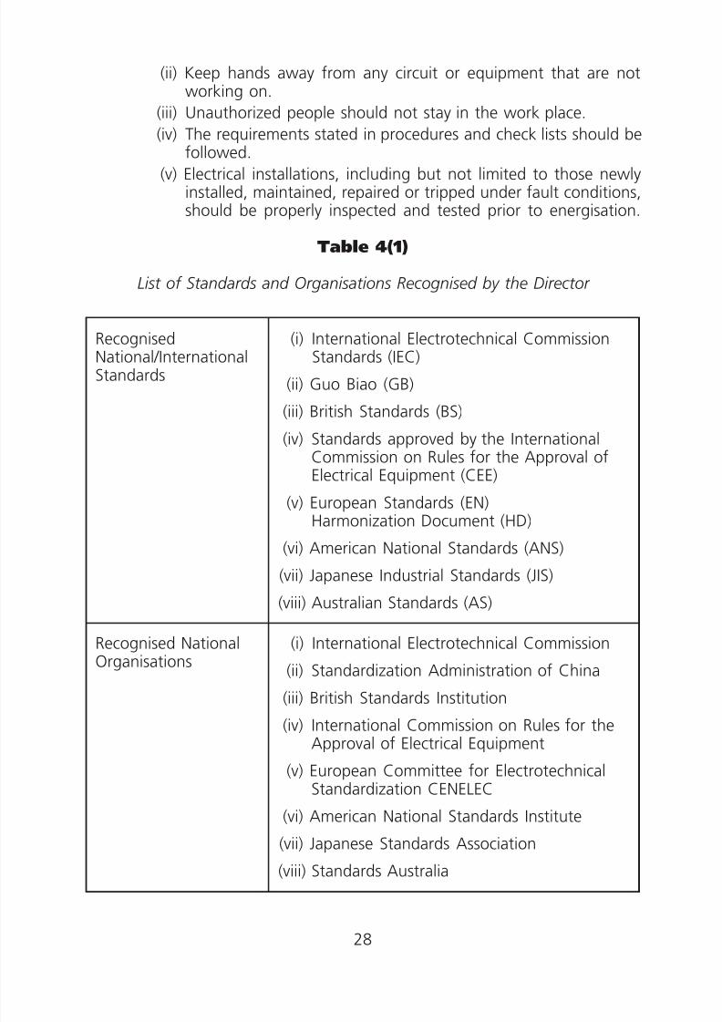
(ii) Keep hands away from any circuit or equipment that are notworking on.
(iii) Unauthorized people should not stay in the work place.
(iv) The requirements stated in procedures and check lists should befollowed.
(v) Electrical installations, including but not limited to those newlyinstalled, maintained, repaired or tripped under fault conditions,should be properly inspected and tested prior to energisation.
Table 4(1)
List of Standards and Organisations Recognised by the Director
Recognised (i) International Electrotechnical CommissionNational/International Standards (IEC)Standards
(ii) Guo Biao (GB)
(iii) British Standards (BS)
(iv) Standards approved by the InternationalCommission on Rules for the Approval ofElectrical Equipment (CEE)
(v) European Standards (EN)Harmonization Document (HD)
(vi) American National Standards (ANS)
(vii) Japanese Industrial Standards (JIS)
(viii) Australian Standards (AS)
Recognised National (i) International Electrotechnical Commission
Organisations (ii) Standardization Administration of China
(iii) British Standards Institution
(iv) International Commission on Rules for theApproval of Electrical Equipment
(v) European Committee for ElectrotechnicalStandardization CENELEC
(vi) American National Standards Institute
(vii) Japanese Standards Association
(viii) Standards Australia
28
8/23/2019 Electricity Wiring
http://slidepdf.com/reader/full/electricity-wiring 29/337
Code 5 SEGREGATION OF CIRCUIT CATEGORIES
5A Circuit Category
5B Segregation of Category 1, 2 and 3 Circuits
(1) General
(2) Category 1 and Category 2 circuits (with enclosures)
(3) Category 3 and Category 1 & 2 circuits (with enclosures)
(4) Category 1, 2 and 3 circuits without enclosure or underground
5C Segregation of Category 4 Circuits and Circuits of Other Categories
5D Segregation of Circuits from Overhead Telecommunication Lines andTelephone Lines
29

8/23/2019 Electricity Wiring
http://slidepdf.com/reader/full/electricity-wiring 30/337
Code 5 SEGREGATION OF CIRCUIT CATEGORIES
5A Circuit Category
(a) There are 4 categories of circuit as defined in the Wiring Regulations asfollows:
(i) Category 1 circuit means a circuit that operates at low voltage, butdoes not include a Category 3 circuit;
(ii) Category 2 circuit means a circuit for telecommunication, radio,telephone, sound distribution, intruder alarm, bell and call, or datatransmission which is supplied with electricity from a safety source,but does not include a Category 3 circuit;
(iii) Category 3 circuit means a circuit for emergency lighting, exit signs,air pressurisation systems and fire services installations including fire
detection and alarm, fire pumps, fireman’s lifts and smokeextraction; and
(iv) Category 4 circuit means a high voltage circuit.
(b) A safety source referred to in subparagraph (a)(ii) above means:
(i) a double-insulated safety isolating transformer to BS EN 61558 orequivalent with its secondary winding being isolated from earth, andhaving a nominal output voltage not exceeding 55 V; or
(ii) a source of electricity providing a degree of safety equivalent to thatof the safety isolating transformer referred to in (i) above (e.g. a
motor-generator with windings providing equivalent isolation); or(iii) a source providing electricity at a voltage not exceeding extra low
voltage and independent of a higher voltage circuit.
(c ) Cables used to connect the battery chargers of self-contained luminairesto the normal mains circuit should NOT be considered as emergencylighting circuits under Category 3 circuit.
5B Segregation of Category 1, 2 and 3 Circuits
(1) General (a) Low voltage circuits should be segregated from extra-low voltage
circuits.
(b) Fire alarm and emergency lighting circuits should be segregatedfrom all other cables and from each other in accordance with BS5839 and BS 5266 or equivalent.
(c ) Telecommunication circuits should be segregated in accordance withBS 6701, BS EN 50174 or equivalent.
(2) Category 1 and Category 2 circuits (with enclosures)
(a) Segregation between Category 1 and Category 2 circuits (withenclosures) should be in compliance with one of the permissiblearrangements listed in Table 5(1).
30

8/23/2019 Electricity Wiring
http://slidepdf.com/reader/full/electricity-wiring 31/337
(b) In conduit, duct, ducting or trunking systems, if common boxes,switchplates or blocks are used for mounting controls or outlets forCategory 1 and Category 2 circuits, rigid partition screens or barriersshould be provided between the cables and connections of the twocategories of circuits.
(3) Category 3 and Category 1 & 2 circuits (with enclosures)
(a) Segregation between Category 3 and Category 1 & 2 circuits (withenclosures) should be in compliance with one of the permissiblearrangements listed in Table 5(2).
(b) Cables of Category 1 circuits are not allowed to be drawn into thesame conduit, duct or ducting as cables of Category 3 circuits.
(c ) Cores of Category 1 and Category 3 circuits are not allowed to be
contained in a common multicore cable, flexible cable or flexible cord.(4) Category 1, 2 and 3 circuits without enclosure or underground
For cables of Category 1, 2 and 3 circuits that are installed withoutenclosure or underground, the following requirements should beobserved:
(a) A minimum horizontal and vertical separation distance of 50 mmshould be provided between Category 1, 2 and 3 circuits.
(b) For cables laid underground or in trench, if the separation distanceof 50 mm cannot be achieved, a separation distance of not less than25 mm is acceptable provided slabs of concrete are insertedbetween Category 1, 2 and 3 circuits. The slabs should be of suchwidth and length that at every point, the shortest path between thecircuits round the concrete should exceed 75 mm.
(c ) At point(s) of crossing for surface wiring of Category 1, 2 and 3circuits, a bridge of durable insulating material at least 6 mm thickshould be used for separation of circuits. The bridge should overlap
the cables of those circuits by at least 25 mm on either side of thepoint of crossing.
5C Segregation of Category 4 Circuits and Circuits of OtherCategories
(a) Cables of Category 4 circuits are not allowed to be drawn into thesame conduit, duct, ducting or trunking as cables of other circuitcategories.
(b) Cores of Category 4 circuits and cores of other circuit categories are
not allowed to be contained in a common multicore cable, flexiblecable or flexible cord.
(c ) For cables of Category 4 that are installed underground or withoutany enclosure, the following points should be observed:
31
8/23/2019 Electricity Wiring
http://slidepdf.com/reader/full/electricity-wiring 32/337
(i) A minimum horizontal or vertical separation distance of 300mm should be provided between Category 4 circuits and circuitsof other categories.
(ii) For cables laid underground, if the separation distance of 300mm cannot be achieved, a reduced separation is acceptable
provided a slab of concrete is inserted between the circuits. Theslab should be at least 50 mm thick and of such width andlength that at every point, the shortest path between thecircuits round the concrete should exceed 180 mm.
5D Segregation of Circuits from OverheadTelecommunication Lines and Telephone Lines
For overhead telecommunication and telephone lines, reference should bemade to relevant Codes of Practice and guidelines issued by relevantauthorities.
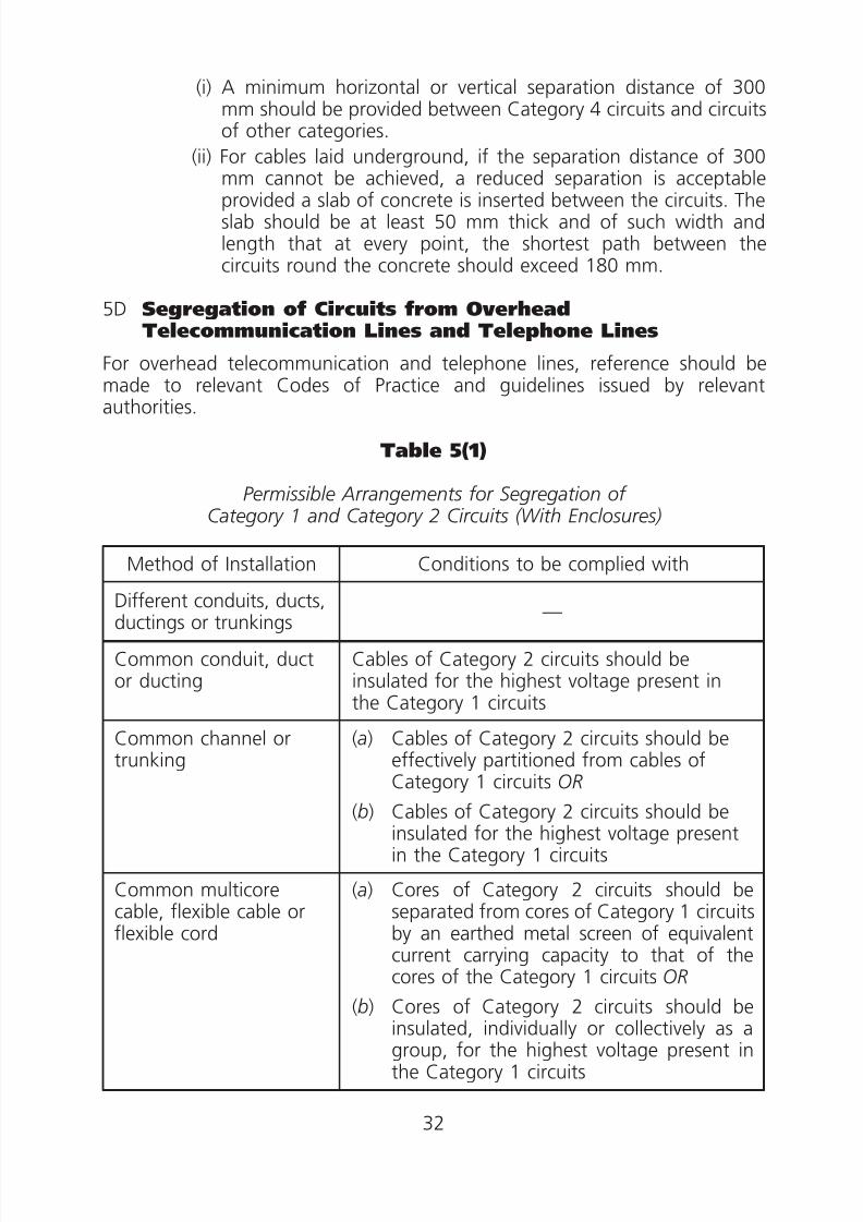
Table 5(1)
Permissible Arrangements for Segregation ofCategory 1 and Category 2 Circuits (With Enclosures)
Method of Installation Conditions to be complied with
Different conduits, ducts,ductings or trunkings
—
Common conduit, ductor ducting
Cables of Category 2 circuits should beinsulated for the highest voltage present inthe Category 1 circuits
Common channel ortrunking
(a) Cables of Category 2 circuits should beeffectively partitioned from cables ofCategory 1 circuits OR
(b) Cables of Category 2 circuits should beinsulated for the highest voltage presentin the Category 1 circuits
Common multicorecable, flexible cable orflexible cord
(a) Cores of Category 2 circuits should beseparated from cores of Category 1 circuitsby an earthed metal screen of equivalentcurrent carrying capacity to that of thecores of the Category 1 circuits OR
(b) Cores of Category 2 circuits should beinsulated, individually or collectively as agroup, for the highest voltage present inthe Category 1 circuits
32
8/23/2019 Electricity Wiring
http://slidepdf.com/reader/full/electricity-wiring 33/337
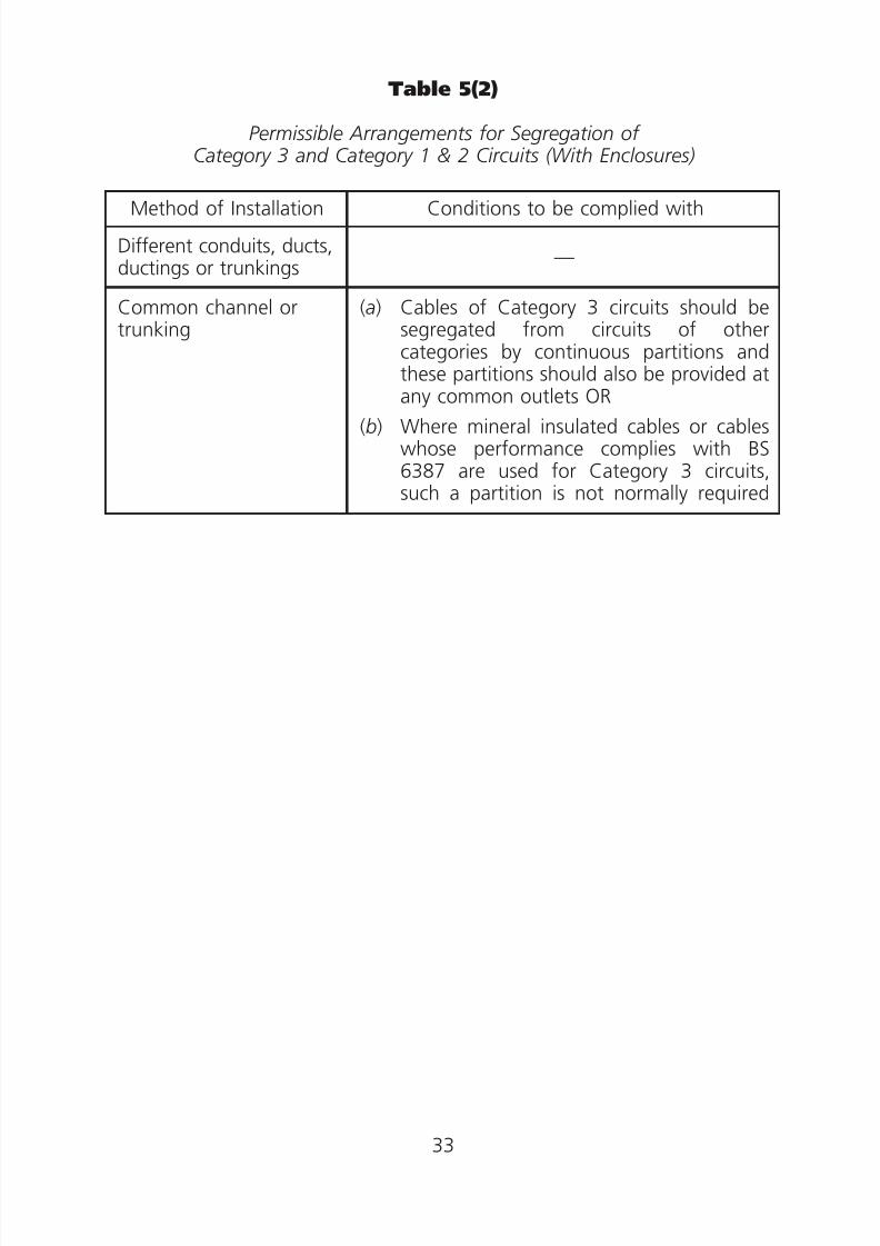
Table 5(2)
Permissible Arrangements for Segregation ofCategory 3 and Category 1 & 2 Circuits (With Enclosures)
Method of Installation Conditions to be complied with
Different conduits, ducts,ductings or trunkings
—
Common channel ortrunking
(a)
(b)
Cables of Category 3 circuits should besegregated from circuits of othercategories by continuous partitions andthese partitions should also be provided at
any common outlets ORWhere mineral insulated cables or cableswhose performance complies with BS6387 are used for Category 3 circuits,such a partition is not normally required
33

8/23/2019 Electricity Wiring
http://slidepdf.com/reader/full/electricity-wiring 34/337
Code 6 CIRCUIT ARRANGEMENT
6A Division of Installation into Circuits
6B Basic Requirements of Circuits
(1) Protection
(2) Control
(3) Identification
(4) Electrical separation for essential circuits
(5) Load distribution
(6) Arrangement of neutral conductor
6C Ring Final Circuit Arrangement
6D Final Circuits Using 5A or 15A Socket Outlets to Requirements Prescribedin Appendix 1
6E Final Circuits Using 13A Socket Outlets to Requirements Prescribed inAppendix 2
(1) General
(2) Spurs
(3) Separate circuits
(4) Permanently connected equipment
6F Final Circuits Using 5A, 15A or 30A Industrial Socket Outlets toRequirements Prescribed in Appendix 3
(1) Socket outlets
(2) Accepted practice
6G Final Circuits Using 16A Industrial Socket Outlets to RequirementsPrescribed in Appendix 4
(1) Socket outlets
(2) Accepted practice
6H Final Circuits Using 32A, 63A or 125A Industrial Socket Outlets toRequirements Prescribed in Appendix 4
(1) Socket outlets
(2) Accepted practice
34

8/23/2019 Electricity Wiring
http://slidepdf.com/reader/full/electricity-wiring 35/337
Code 6 CIRCUIT ARRANGEMENT
6A Division of Installation into Circuits
(a) An electrical installation should be divided into circuits where necessaryor practicable and each circuit should be separately protected andcontrolled.
(b) A schematic wiring diagram showing the main distribution system shouldbe displayed near the main switch with rating 100A or above.
6B Basic Requirements of Circuits
(1) Protection
(a) Each circuit should be protected by an overcurrent protective device
with its operating current value closely related to the currentdemand of the current using equipment connected or intended tobe connected to it and to the current carrying capacity of theconductor connected. This arrangement will avoid danger in theevent of a fault by ensuring prompt operation of the protectivedevice at the appropriate current value which will otherwise causedamage to the cable or the current using equipment.
(b) A fault on one circuit should not result in the shutting down of anyunrelated parts of the installation as far as reasonably practicable.
For this, it is recommended that—
(i) fixed lighting fittings of an installation should be arranged to befed by two or more final circuits;
(ii) lighting final circuits should be electrically separated from powercircuits except that it may be connected to bell transformers orelectric clocks;
(iii) power circuits for kitchens should be electrically separated fromother power circuits.
(c ) Where the supply is designed to be taken from more than onetransformer, interconnection facilities between the main incomingcircuit breakers should be provided if requested by the electricitysupplier. All incoming and interconnection circuit breakers should beof 4-pole type interrupting all live conductors (i.e. phase and neutralconductors) and electrically and mechanically interlocked to preventthe electricity supplier’s transformers from operating in parallel.
(Note: Castell key interlock is one of the acceptable means of
mechanical interlock. When an installation utilizes more thanone set of castell key interlocks, each set of keys should bedifferent from others so that the key can only be inserted tothe switchgear intended to be controlled. No redundantcastell keys should be readily available.)
35

8/23/2019 Electricity Wiring
http://slidepdf.com/reader/full/electricity-wiring 36/337
(2) Control
Each circuit should be provided with means of interrupting the supply onload and isolation for electrical servicing and testing purposes withoutaffecting other circuits.
(3) Identification
(a) Protective devices of each circuit should be clearly labelled oridentified so that the rating of the devices and the circuits theyprotect can be easily recognised.
(b) Every socket in a three phase installation should be marked with theappropriate phase identification (e.g. L1, L2 and L3 etc.) in apermanent manner.
(4) Electrical separation for essential circuits
Final circuits for emergency lighting, fire fighting equipment andfireman’s lift should be electrically separated from one another and fromother circuits.
(5) Load distribution
Single phase loads in an installation with a three phase supply should beevenly and reasonably distributed among the phases.
(6) Arrangement of neutral conductor
(a) Neutral conductor of a single phase circuit should not be shared withany other circuit.
(b) Neutral conductor of a three phase circuit should only be sharedwith its related phases in a three phase four wire system.
(c ) For a polyphase circuit, the neutral conductor should have at leastthe full size of current carrying live conductors to cater for anyimbalance or harmonic currents which may occur in normal services.For balanced three-phase systems where the total harmonic
distortion due to third harmonic current or multiples of the thirdharmonic is greater than 15% of the fundamental line current, therating factors given in Appendix 11 of BS 7671 should be taken intoaccount.
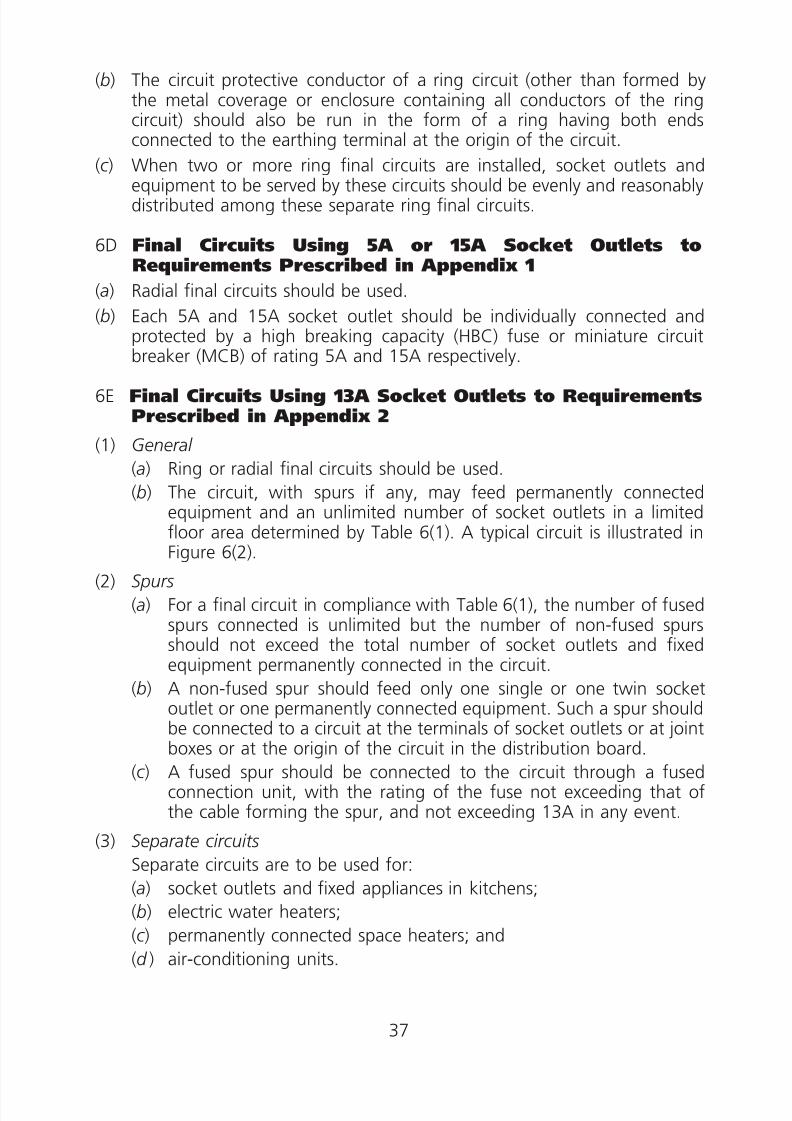
6C Ring Final Circuit Arrangement
(a) The circuit conductor of a ring circuit should be run in the form of a ring,commencing from the origin of the circuit in the distribution board,looping into the terminal of socket outlets connected in the ring, and
returning to the same point of the circuit as illustrated in Figure 6(1).
36
8/23/2019 Electricity Wiring
http://slidepdf.com/reader/full/electricity-wiring 37/337
(b) The circuit protective conductor of a ring circuit (other than formed bythe metal coverage or enclosure containing all conductors of the ringcircuit) should also be run in the form of a ring having both endsconnected to the earthing terminal at the origin of the circuit.
(c ) When two or more ring final circuits are installed, socket outlets and
equipment to be served by these circuits should be evenly and reasonablydistributed among these separate ring final circuits.
6D Final Circuits Using 5A or 15A Socket Outlets toRequirements Prescribed in Appendix 1
(a) Radial final circuits should be used.
(b) Each 5A and 15A socket outlet should be individually connected andprotected by a high breaking capacity (HBC) fuse or miniature circuit
breaker (MCB) of rating 5A and 15A respectively.
6E Final Circuits Using 13A Socket Outlets to RequirementsPrescribed in Appendix 2
(1) General
(a) Ring or radial final circuits should be used.
(b) The circuit, with spurs if any, may feed permanently connectedequipment and an unlimited number of socket outlets in a limitedfloor area determined by Table 6(1). A typical circuit is illustrated inFigure 6(2).
(2) Spurs
(a) For a final circuit in compliance with Table 6(1), the number of fusedspurs connected is unlimited but the number of non-fused spursshould not exceed the total number of socket outlets and fixedequipment permanently connected in the circuit.
(b) A non-fused spur should feed only one single or one twin socketoutlet or one permanently connected equipment. Such a spur should
be connected to a circuit at the terminals of socket outlets or at jointboxes or at the origin of the circuit in the distribution board.
(c ) A fused spur should be connected to the circuit through a fusedconnection unit, with the rating of the fuse not exceeding that ofthe cable forming the spur, and not exceeding 13A in any event.
(3) Separate circuits
Separate circuits are to be used for:
(a) socket outlets and fixed appliances in kitchens;
(b) electric water heaters;(c ) permanently connected space heaters; and
(d ) air-conditioning units.
37

8/23/2019 Electricity Wiring
http://slidepdf.com/reader/full/electricity-wiring 38/337
(4) Permanently connected equipment
Equipment, except shaver supply unit complying with BSEN 61558-2-5 orequivalent, connected permanently (i.e. not through a plug-socketarrangement) to a final circuit arranged in accordance with Table 6(1)should be locally protected by a fuse of rating not exceeding 13A and
should be controlled by a switch in a readily accessible position orprotected by a miniature circuit breaker of rating not exceeding 16A. Thisis illustrated in Figure 6(3).
6F Final Circuits Using 5A, 15A or 30A Industrial SocketOutlets to Requirements Prescribed in Appendix 3
(1) Socket outlets
These are protected type non-reversible socket outlets. Socket outletwithout a key and a keyway is for use with non-fused plug and anexclusive radial final circuit must be used for the socket outlet. Socketoutlet with a key and a keyway is for use with fused plug.
(2) Accepted practice
(a) Either radial or ring final circuits may be used.
(b) The current demand of the equipment fed by the circuit will dependon the type of equipment and the operational requirements, andshould not exceed the rating of the overcurrent protective device. In
assessing the current demand, no diversity is allowed forpermanently connected equipment.
(c ) The overcurrent protective device should have a rating not exceeding32A.
(d ) The number of socket outlets can be unlimited.
(e) The total current demand of socket outlets served by a fused spurshould not exceed 16A.
(f ) A fused spur should be connected to a circuit through a fusedconnection unit with the rating of the fuse in the unit not exceedingthat of the cable forming the spur and, in any event, not exceeding16A.
( g) Non-fused spurs should not be used.
(h) Equipment permanently connected to a circuit should be locallyprotected and controlled by a fuse of rating not exceeding 16Atogether with a switch, or by a miniature circuit breaker of rating notexceeding 16A.
(i ) Figure 6(4) illustrates such a circuit arrangement.
38

8/23/2019 Electricity Wiring
http://slidepdf.com/reader/full/electricity-wiring 39/337
6G Final Circuits Using 16A Industrial Socket Outlets toRequirements Prescribed in Appendix 4
(1) Socket outlets
These are industrial socket outlets with retaining devices for either indoor
or outdoor applications and are for single-phase or three-phase supplies.
(2) Accepted practice
(a) Only radial final circuits should be used.
(b) Fused or non-fused spur is not allowed.
(c ) The current demand of the equipment fed by the circuit will dependon the type of equipment and the operational requirements, andshould not exceed the rating of the overcurrent protective device.
(d ) The overcurrent protective device should have a rating not exceeding20A.
(e) The number of socket outlets can be unlimited.
(f ) Figure 6(5) illustrates such a circuit arrangement.
6H Final Circuits Using 32A, 63A or 125A Industrial SocketOutlets to Requirements Prescribed in Appendix 4
(1) Socket outletsThese are industrial socket outlets with retaining devices for either indooror outdoor applications and are for single phase or three phase supplies.
(2) Accepted practice
(a) Only exclusive radial final circuits should be used.
(b) The number of socket outlets in a final circuit should not be morethan one.
(c ) The overcurrent protective device should have a rating not exceeding
the rating of the socket outlet or that of the cable forming thecircuit.
39

8/23/2019 Electricity Wiring
http://slidepdf.com/reader/full/electricity-wiring 40/337
0.
Table 6(1)
Final Circuits Using 13A Socket OutletsComplying to Requirements Prescribed in Appendix 2
Type of Circuit
Rating ofOvercurrent
Protective Device(HBC fuse or
MiniatureCircuit Breaker)
Min. CopperConductor Sizeof Rubber orPVC InsulatedCable for theCircuit and
Non-fused Spur(Note)
Maximum FloorArea Served
A1 RingA2 RadialA3 Radial
(Ampere)
30 or 3230 or 32
20
(mm2)
2.542.5
(m2)
1005020
Note: 1. If cables of two or more circuits are bunched together or theambient air temperature exceeds 30°C the size of conductorshould be increased and appropriate correction factors (seeAppendix 5) should be applied such that the conductor sizeshould correspond to a current carrying capacity not less than:
(i) 20A for A1 or A3 circuits(ii) 30A or 32A for A2 circuits
2. The conductor size of a fused spur should be determined fromthe total current demand served by that spur, which is limited toa maximum of 13A. When such spur serves socket outlets, theminimum conductor size is 1.5 mm2 for rubber or PVC insulatedcables, copper conductors.
40
8/23/2019 Electricity Wiring
http://slidepdf.com/reader/full/electricity-wiring 41/337
41

8/23/2019 Electricity Wiring
http://slidepdf.com/reader/full/electricity-wiring 42/337
42

8/23/2019 Electricity Wiring
http://slidepdf.com/reader/full/electricity-wiring 43/337
43

8/23/2019 Electricity Wiring
http://slidepdf.com/reader/full/electricity-wiring 44/337
44

8/23/2019 Electricity Wiring
http://slidepdf.com/reader/full/electricity-wiring 45/337
45

8/23/2019 Electricity Wiring
http://slidepdf.com/reader/full/electricity-wiring 46/337
Code 7 CURRENT DEMAND
7A Current Demand of a Circuit
7B Determination of Current Demand
(1) General
(2) For circuit supplying non-simultaneous or cyclic loads
(3) For final circuits
(4) For circuits supplying a number of final circuits
46
8/23/2019 Electricity Wiring
http://slidepdf.com/reader/full/electricity-wiring 47/337
Code 7 CURRENT DEMAND
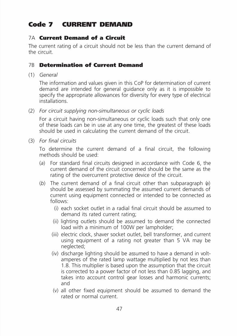
7A Current Demand of a Circuit
The current rating of a circuit should not be less than the current demand of
the circuit.
7B Determination of Current Demand
(1) General
The information and values given in this CoP for determination of currentdemand are intended for general guidance only as it is impossible tospecify the appropriate allowances for diversity for every type of electricalinstallations.
(2) For circuit supplying non-simultaneous or cyclic loads
For a circuit having non-simultaneous or cyclic loads such that only oneof these loads can be in use at any one time, the greatest of these loadsshould be used in calculating the current demand of the circuit.
(3) For final circuits
To determine the current demand of a final circuit, the followingmethods should be used:
(a) For standard final circuits designed in accordance with Code 6, thecurrent demand of the circuit concerned should be the same as therating of the overcurrent protective device of the circuit.
(b) The current demand of a final circuit other than subparagraph (a)should be assessed by summating the assumed current demands ofcurrent using equipment connected or intended to be connected asfollows:
(i) each socket outlet in a radial final circuit should be assumed todemand its rated current rating;
(ii) lighting outlets should be assumed to demand the connectedload with a minimum of 100W per lampholder;
(iii) electric clock, shaver socket outlet, bell transformer, and currentusing equipment of a rating not greater than 5 VA may beneglected;
(iv) discharge lighting should be assumed to have a demand in volt-amperes of the rated lamp wattage multiplied by not less than1.8. This multiplier is based upon the assumption that the circuit
is corrected to a power factor of not less than 0.85 lagging, andtakes into account control gear losses and harmonic currents;and
(v) all other fixed equipment should be assumed to demand therated or normal current.
47
8/23/2019 Electricity Wiring
http://slidepdf.com/reader/full/electricity-wiring 48/337
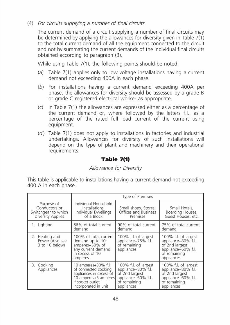
(4) For circuits supplying a number of final circuits
The current demand of a circuit supplying a number of final circuits maybe determined by applying the allowances for diversity given in Table 7(1)to the total current demand of all the equipment connected to the circuitand not by summating the current demands of the individual final circuitsobtained according to paragraph (3).
While using Table 7(1), the following points should be noted:
(a) Table 7(1) applies only to low voltage installations having a currentdemand not exceeding 400A in each phase.
(b) For installations having a current demand exceeding 400A perphase, the allowances for diversity should be assessed by a grade Bor grade C registered electrical worker as appropriate.
(c ) In Table 7(1) the allowances are expressed either as a percentage ofthe current demand or, where followed by the letters f.l., as apercentage of the rated full load current of the current usingequipment.
(d ) Table 7(1) does not apply to installations in factories and industrialundertakings. Allowances for diversity of such installations willdepend on the type of plant and machinery and their operationalrequirements.
Table 7(1)
Allowance for Diversity
This table is applicable to installations having a current demand not exceeding400 A in each phase.
Purpose ofConductors or
Switchgear to whichDiversity Applies
Type of Premises
Individual HouseholdInstallations,
Individual Dwellingsof a Block
Small shops, Stores,
Offices and BusinessPremises
Small Hotels,
Boarding Houses,Guest Houses, etc.
1. Lighting 66% of total currentdemand
90% of total currentdemand
75% of total currentdemand
2. Heating andPower (Also see3 to 10 below)
100% of total currentdemand up to 10amperes+50% ofany current demandin excess of 10amperes
100% f.l. of largestappliance+75% f.l.of remainingappliances
100% f.l. of largestappliance+80% f.l.of 2nd largestappliance+60% f.l.of remainingappliances
3. CookingAppliances
10 amperes+30% f.l.of connected cookingappliances in excess of10 amperes+5 amperesif socket outletincorporated in unit
100% f.l. of largestappliance+80% f.l.of 2nd largestappliance+60% f.l.of remainingappliances
100% f.l. of largestappliance+80% f.l.of 2nd largestappliance+60% f.l.of remainingappliances
48

8/23/2019 Electricity Wiring
http://slidepdf.com/reader/full/electricity-wiring 49/337
Purpose ofConductors or
Switchgear to whichDiversity Applies
Type of Premises
Individual HouseholdInstallations,
Individual Dwellingsof a Block
Small shops, Stores,Offices and Business
Premises
Small Hotels,Boarding Houses,
Guest Houses, etc.
4. Motors (otherthan lift motors,see 8)
— 100% f.l. of largestmotor+80% f.l. of2nd largest motor+60% f.l. of remainingmotors
100% f.l. of largestmotor+50% f.l. ofremaining motors
5. Water-Heaters(instantaneoustype)
100% f.l. of largestappliance+100% f.l.of 2nd largestappliance+25% f.l.of remainingappliances
100% f.l. of largestappliance+100% f.l.of 2nd largestappliance+25% f.l.of remainingappliances
100% f.l. of largestappliance+100% f.l.of 2nd largestappliance+25% f.l.of remainingappliances
6. Water Heaters(thermostaticallycontrolled)
No diversity allowable
Note: It is important to ensure that the distribution board is ofsufficient rating to take the total load connected to it withoutthe application of any diversity.
7. Thermal StorageSpace HeatingInstallations
8. Lift motors Note: Subject to requirements specified by the lift engineer registeredunder Cap. 327, Lifts & Escalators (Safety) Ordinance.
9. Water Pumps 100% f.l. of the largest pump motor and 25% of the remainingmotors
10.Air conditioners 100% f.l. of theair-conditioner(s) inthe bed-room(s) or inthe living room(s),whichever is largerand 40% f.l. of theremainingair-conditioner(s)
100% of currentdemand of largestpoint of utilisation+75% of currentdemand of every otherpoint of utilisation
100% of currentdemand of largestpoint of utilisation+75% of currentdemand of every otherpoint of utilisation
11.Arrangements ofFinal Circuits inaccordance with
code 6D
100% of currentdemand of largestcircuit+30% of
current demand ofevery other circuit
100% of current demand of largest circuit+40% of current demand of every other circuit
12.Arrangements ofFinal Circuits inaccordance withcode 6E
100% of currentdemand of largestcircuit+40% ofcurrent demand ofevery other circuit
100% of current demand of largest circuit+50% of current demand of every other circuit
13.Fixed Equipmentof the same typee.g. Refrigeratorsand freezers
other than thoselisted above
100% of currentdemand of largestpoint of utilisation+40% of current
demand of every otherpoint of utilisation
100% of currentdemand of largestpoint of utilisation+75% of current
demand of every otherpoint of utilisation
100% of currentdemand of largestpoint of utilisation+75% of current
demand of every pointin main rooms (diningrooms, etc.) + 40%of every other point ofutilisation
49
8/23/2019 Electricity Wiring
http://slidepdf.com/reader/full/electricity-wiring 50/337
Code 8 ISOLATION AND SWITCHING
8A Provision of Isolation and Switching
(1) General installation
(2) Appliance, equipment or luminaire
(3) Unguarded moving parts
(4) Electric motors
(5) Switching off for mechanical maintenance
(6) Emergency switching
8B Requirements of Isolation and Switching Devices
(1) General
(2) Isolating devices
(3) Devices for switching off for mechanical maintenance
(4) Devices for emergency switching
50
8/23/2019 Electricity Wiring
http://slidepdf.com/reader/full/electricity-wiring 51/337
Code 8 ISOLATION AND SWITCHING
8A Provision of Isolation and Switching
(1) General installation
(a) An installation must be provided with a main switch or circuitbreaker and a means of isolation to cut off all voltages. These twofunctions may be incorporated in a single device. The main switch orcircuit breaker should interrupt all live conductors (i.e. phase andneutral conductors) and be capable of cutting off the full loadcurrent of the installation from supply. For a 3-phase 4-wire a.c.supply, a linked switch or linked circuit breaker may be arranged todisconnect the phase conductors only and in such case, a link shouldbe inserted in the neutral conductor and securely fixed by bolts orscrews.
(b) For an installation serving more than one building, the installationinside separate buildings should be treated as a separate installation,and a separate main switch or circuit breaker and a separate meansof isolation for each building are required as in subparagraph (a).
(c ) Every circuit or group of circuits must be provided with:
(i) a means of isolation; and
(ii) a means of interrupting the supply on load.(d ) Where a standby generator is installed, electrically and mechanically
interlocked 4-pole changeover devices should be used forinterconnection between the normal and standby sources to ensurethat any neutral unbalance and fault current return to the correctsource of supply.
(e) Under no circumstances must a means of isolation or a switchingdevice be provided in a protective conductor.
(f ) A circuit breaker used to receive supply direct from the electricitysupplier’s transformer should normally be of draw-out type. Anisolator may be used in conjunction with a fixed type circuit breakerprovided that it is mechanically interlocked with the circuit breaker.
(2) Appliance, equipment or luminaire
(a) An appliance, equipment or luminaire, other than that connected bymeans of a plug and socket outlet should be provided with a meansof interrupting the supply on load.
(b) For electric discharge lighting installation operating normally at anopen-circuit voltage exceeding low voltage, an effective local meansfor isolation of the circuit from supply (such means being additionalto the switch normally used for controlling the circuit) should be
51

8/23/2019 Electricity Wiring
http://slidepdf.com/reader/full/electricity-wiring 52/337
provided for the isolation of every self-contained luminaire, or ofevery circuit supplying luminaires at a voltage exceeding low voltage.
(3) Unguarded moving parts
An installation where it is necessary for a person or persons to enter orwork in close proximity with normally unguarded moving parts whichmay constitute a hazard should be provided with a means of isolationnear the moving parts in addition to any emergency switching provided.
(4) Electric motors
Electric motors except exhaust fans having rated power not exceeding50W and servo-motors should be provided with:
(a) means of isolation suitably placed and so connected that all voltagesmay thereby be cut off from the motor and all apparatus includingany automatic circuit breaker used therewith. If this means ofisolation is remote from a motor, an additional means of isolationadjacent to the motor should be installed or alternatively provisionshould be made so that the means of isolation can be securedagainst inadvertent operation as required by Code 8B(2)( g);
(b) means for starting and stopping, suitably placed for ready operation;and
(c ) means to prevent automatic restarting after a stoppage due to dropin voltage or failure of supply, where unexpected restarting of themotor might cause danger. Such means is not required where thefailure of the motor to start after a brief interruption of the supplywould be likely to cause greater danger, e.g. motors driving aventilation fan of a fire protection system. This requirement does notpreclude any arrangement for starting a motor at intervals by anautomatic control device, where other adequate precautions are
taken against danger from unexpected restarting, e.g. varioussequential drives in an automatic processing plant, use of safetyequipment such as guards, barriers, etc.
(5) Switching off for mechanical maintenance
(a) Means of switching off for mechanical maintenance must beprovided where mechanical maintenance may involve a risk of burnsor a risk of injury from mechanical movement. These include everycircuit supplying:
(i) an electric motor;(ii) electrical heating equipment;
(iii) electromagnetic equipment which may cause mechanicalaccidents;
52

8/23/2019 Electricity Wiring
http://slidepdf.com/reader/full/electricity-wiring 53/337
(iv) luminaires (lamp replacement and cleaning are included asmechanical maintenance); and
(v) any other electrically energised equipment from which possiblemechanical or heat hazards can arise from the use of electricalenergy.
(b) Suitable means should be provided to prevent electrically poweredequipment from becoming unintentionally reactivated duringmechanical maintenance, unless the means of switching off iscontinuously under the control of any person performing suchmaintenance.
(c ) Where electrically powered equipment is within the scope of BS EN60204, the requirements for switching off for mechanicalmaintenance of that standard apply.
(6) Emergency switching
(a) Means should be provided for emergency switching of any part ofan installation where it may be necessary to control the supply toremove an unexpected danger.
(b) Means for emergency switching should be provided for the purposeof cutting off the appropriate supply to the circuit concerned asrapidly as possible in order to obviate or to remove a dangerous
condition as soon as it becomes apparent. A typical example wheremeans for emergency switching should be provided is a machinedriven by electrical means which may give rise to danger.
(c ) Where electrically powered equipment is within the scope of BS EN60204, the requirements for emergency switching of that standardapply.
8B Requirements of Isolation and Switching Devices
(1) General
Where a common device is used to perform one or more of the followingfunctions:
(a) means of isolation;
(b) means of switching off for mechanical maintenance;
(c ) means of emergency switching,
the arrangement and characteristics of the device should satisfy all therequirements of this Code 8 for the various functions concerned.
53
8/23/2019 Electricity Wiring
http://slidepdf.com/reader/full/electricity-wiring 54/337
(2) Isolating devices
(a) An isolating device should be capable of:
(i) opening and closing all live conductors (i.e. phase and neutralconductors) of the circuit under no-load condition provided
that, for a 3-phase 4-wire a.c. supply, a linked isolator may bearranged to disconnect the phase conductors only and in suchcase, a link should be inserted in the neutral conductor andsecurely fixed by bolts or screws;
(ii) carrying the normal circuit current;
(iii) carrying for a specified time abnormal currents which may occurduring an overcurrent condition (i.e. overload or short-circuit).
(b) The position of the contacts or other means of isolation should beeither externally visible or clearly and reliably indicated. An indicationof the isolated position should occur only when the specifiedisolation has been obtained in each pole.
(c ) An isolating device should be designed and/or installed so as toprevent unintentional or inadvertent closure.
(d ) The following devices satisfying subparagraphs (a), (b) and (c ) areacceptable as means of isolation:
(i) isolators (disconnectors),
(ii) fuse switches and switch-fuses,(iii) links, including fuse-links and fuse cut-outs,
(iv) plugs and socket outlets,
(v) cable couplers,
(vi) circuit breakers, including miniature circuit breakers (MCB),moulded case circuit breakers (MCCB) and residual currentcircuit breakers (RCCB).
(e) Emergency stop push button and semiconductor devices, such as a
‘touch control switch’ or ‘photo-electric switch’, must not be usedfor isolation.
(f ) Where an isolating device for a particular circuit is placed remotelyfrom the equipment to be isolated, provision should be made so thatthe means of isolation can be secured in the open position. Wherethis provision takes the form of a lock or removable handle, the keyor handle should be non-interchangeable with any other used for asimilar purpose within the premises.
( g) Each device used for isolation should be clearly identified by positionor durable marking to indicate the installation or circuit it isolates.
54

8/23/2019 Electricity Wiring
http://slidepdf.com/reader/full/electricity-wiring 55/337
(3) Devices for switching off for mechanical maintenance
(a) A device used for switching off for mechanical maintenance should:
(i) require manual operation;
(ii) have visible or clearly and reliably indicated open and closed
positions of the contacts;(iii) be designed and/or installed in such a way to prevent
inadvertent or unintentional switching on;
(iv) be capable of cutting off the full load current of the relevantpart of the installation; and
(v) be readily accessible for operation.
(b) The following devices satisfying subparagraph (a) are acceptable asmeans for switching off for mechanical maintenance:
(i) switches,(ii) circuit breakers,
(iii) control switches operating contactors,
(iv) plugs and socket outlets.
(4) Devices for emergency switching
(a) Means for emergency switching should act as directly as possible onthe appropriate supply conductors. The arrangement should be such
that one single action only will interrupt the appropriate supply.(b) Means of interrupting the supply for the purpose of emergency
switching should be capable of cutting off the full load current ofthe relevant part(s) of the installation.
(c ) The means of operation should be capable of latching or beingrestrained in the ‘off’ or ‘stop’ position, unless both the means ofoperation for emergency switching and for re-energising are underthe control of the same person. The release of an emergency
switching device should not re-energise the relevant part of theinstallation.
(d ) Means of operating (handle, push-button, etc.) a device foremergency switching should be:
(i) clearly marked;
(ii) preferably coloured red; and
(iii) installed in a readily accessible position where danger mightoccur and, where appropriate, at any additional remote position
from which that danger can be removed.(e) The following devices satisfying subparagraph (d ) are acceptable as
emergency switches:
55

8/23/2019 Electricity Wiring
http://slidepdf.com/reader/full/electricity-wiring 56/337
(i) switch in the main circuit (e.g. fireman’s switch for high voltagedischarge lighting installation),
(ii) push button and the like in a control or auxiliary circuit (e.g.emergency stop for machinery).
(f ) A plug and socket outlet or similar device should not be selected asa device for emergency switching.
( g) Fireman’s emergency switch should:
(i) be coloured red and have fixed on or near it a permanentdurable nameplate marked with the words ‘消防員開關掣 FIREMAN’S SWITCH’ (the nameplate should have a minimumsize of 150 mm by 100 mm and the lettering should be easilylegible from a distance appropriate to the site conditions but inno case less than 13 mm high);
(ii) have its ‘ON’ and ‘OFF’ positions clearly indicated by letteringlegible to a person standing on the ground at the intended site,with the ‘OFF’ position at the top;
(iii) be provided with a device to prevent the switch beinginadvertently returned to the ‘ON’ position; and
(iv) be arranged to facilitate operation by a fireman.
56

8/23/2019 Electricity Wiring
http://slidepdf.com/reader/full/electricity-wiring 57/337
Code 9 OVERCURRENT PROTECTIVE DEVICES
9A General Requirements
(1) Overcurrent protection for circuit
(2) Examples of overcurrent protective devices
(3) Requirements of overcurrent protective devices
9B Relation Between Circuit Conductors and Overcurrent Protective Devices
(1) Overload protective devices
(2) Faults current protective devices
9C Breaking Capacity of Overcurrent Protective Devices
(1) Overload protective devices
(2) Fault current protective devices
9D Position of Overcurrent Protective Devices
(1) General
(2) Overload protective devices
(3) Fault current protective devices
9E Other Requirements of Overcurrent Protective Devices
57

8/23/2019 Electricity Wiring
http://slidepdf.com/reader/full/electricity-wiring 58/337
Code 9 OVERCURRENT PROTECTIVE DEVICES
9A General Requirements
(1) Overcurrent protection for circuit
Every circuit must be protected by one or more devices for automaticinterruption of the supply in the event of overcurrent resulting from:
(a) overload, or
(b) fault.
(2) Examples of overcurrent protective devices
The following devices are acceptable as protective devices againstovercurrent:
(a) Miniature Circuit Breakers (MCB)
(b) Moulded Case Circuit Breakers (MCCB)
(c ) High Breaking Capacity (HBC) Fuses
(d ) Semi-enclosed Fuses
(e) Circuit Breakers incorporating overcurrent release, or in conjunctionwith fuse.
(3) Requirements of overcurrent protective devices(a) Overload protective devices and fault current protective devices
should satisfy the requirements of Codes 9B, 9C, 9D and 9E.
(b) For devices providing protection against both overload current andfault current, they should satisfy both the requirements of overloadprotective devices and fault current protective devices.
(c ) The characteristics of devices for overload protection should becoordinated so that the energy let-through by the fault currentprotective device does not exceed that which can be withstood bythe overload protective device without damage. For a circuitincorporating a motor starter, this CoP does not preclude the type ofco-ordination described in IEC 60947-4-1, in respect of which theadvice of the manufacturer of the starter should be sought.
9B Relation Between Circuit Conductors and OvercurrentProtective Devices
(1) Overload protective devices
(a) Overload protective devices should be capable of breaking anyoverload current flowing in the circuit conductors before such acurrent could cause a temperature rise detrimental to insulation, joints, terminations, or surroundings of the conductors.
58

8/23/2019 Electricity Wiring
http://slidepdf.com/reader/full/electricity-wiring 59/337
(b) The nominal current or current setting of the devices should not beless than the design current of the circuit.
(c ) The nominal current or current setting of the devices should notexceed the lowest of the current carrying capacities of any of theconductors in the circuit.
(d ) The current causing effective operation of the devices should notexceed 1.45 times the lowest of the current carrying capacities ofany of the conductors of the circuit.
(Note: (i) If the device is a fuse to BS88 part 2 or part 6 or BS1361 ora circuit breaker to IEC 60898 or equivalent satisfyingrequirement (c ), it is also considered to have satisfiedrequirement (d ).
(ii) If the device is a semi-enclosed fuse to BS3036, compliance
with requirement (d ) is afforded if its nominal current doesnot exceed 0.725 times the current carrying capacity of thelowest rated conductor in the circuit protected.)
(e) When the same protective device protects conductors in parallel,other than that of ring circuits, the value for ‘the lowest of thecurrent carrying capacities’ mentioned in subparagraphs (c ) and (d )may be taken as the sum of the current carrying capacities of thoseconductors in parallel provided that those conductors:
(i) are of the same construction, material and cross-sectional area,and are approximately the same length, and appropriate phasedisposition;
(ii) have no branch circuits throughout their length; and
(iii) are arranged so as to carry substantially equal currents.
(2) Fault current protective devices
(a) Fault current protective devices should be capable of breaking anyfault current in the conductors of each circuit before such currentcould cause danger due to thermal and mechanical effects producedin conductors and connections.
(b) The devices should be able to interrupt all currents caused by a faultoccurring at any point of the circuit in a time not exceeding thatwhich brings the cable conductors to their limiting final temperature.
(Note: Table 9(1) gives the limiting final temperatures for some commonmaterials.)
9C Breaking Capacity of Overcurrent Protective Devices
(1) Overload protective devices
59

8/23/2019 Electricity Wiring
http://slidepdf.com/reader/full/electricity-wiring 60/337
Overload protective devices may have a breaking capacity below thevalue of the prospective fault current at the point where the device isinstalled provided that such devices are protected against fault current.
(2) Fault current protective devices
(a) Fault current protective devices should have a breaking capacity notless than the prospective fault current at the point where the deviceis installed except if the following requirement in subparagraph (b)applies.
(b) The device may be permitted to have a lower breaking capacityprovided that another protective device having the necessarybreaking capacity is installed on the supply side. The characteristicsof the devices should be coordinated so that the energy let-through
of these two devices will not cause damage to the load side deviceand the conductors protected by these devices.
(c ) The breaking capacities of protective devices against fault currentshould be assessed for all installations. Table 9(2) shows theminimum breaking capacities for general guidance only.
9D Position of Overcurrent Protective Devices
(1) General
Overcurrent protective devices should be located in places readilyaccessible for maintenance.
(2) Overload protective devices
(a) Overload protective devices, subject to subparagraph (b), should beplaced where a reduction occurs in the value of current carryingcapacity of the conductors of the installation.
(b) The device may be placed at any point along the run of thoseconductors provided that the part of run between the point wherethe value of current carrying capacity is reduced and the position ofthe protective device has no branch circuits or outlets for theconnection of current using equipment.
(3) Fault current protective devices
(a) Fault current protective devices, subject to subparagraph (b) and (c ),should be placed where a reduction occurs in the value of currentcarrying capacity of the conductors of the installation.
(b) The device may be placed at any point along the run of thoseconductors provided that between the point where the value of
60

8/23/2019 Electricity Wiring
http://slidepdf.com/reader/full/electricity-wiring 61/337
current carrying capacity is reduced and the position of theprotective device provided that the conductors are:
(i) not exceed 3m in length, and
(ii) be erected in such a manner as to reduce the risk of fault, fireor danger to persons to a minimum.
(c ) The device may be placed at a point other than specified insubparagraph (a) provided that the conductors between the deviceand the point of reduction in current carrying capacity areadequately protected against fault current according to Code 9B(2)by a fault current protective device installed on the supply side of thepoint of reduction.
9E Other Requirements of Overcurrent Protective Devices
(a) Overcurrent protective devices should be placed in enclosure that arefree from easily ignitable materials.
(b) Every overcurrent protective device should be provided on oradjacent to it an indication of its intended nominal current asappropriate to the circuit it protects.
(c ) Fuses which are likely to be removed or replaced whilst the circuitsthey protect are energised, should be of a type such that they can bethus removed or replaced without danger.
(d ) Suitable tools for safe withdrawal of fuses at a fuse board should beprovided where necessary.
(e) Where circuit breakers may be operated by persons other than aregistered electrical worker, they should be designed or installed sothat it is not possible to modify the setting or the calibration of theirovercurrent releases without a deliberate act involving either the useof a key or tool. A visible indication of the setting or calibration isrecommended.
(f ) Operating handles of circuit breakers should be made accessiblewithout opening any door or cover giving access to live parts.
( g) All linked circuit breakers for overcurrent protection of equipmentrun on polyphase supply must be purposely designed by themanufacturer to enable breaking of all related phase conductorssimultaneously. Any modified miniature circuit breaker to achieve asa linked circuit breaker is not acceptable.
(h) When a consumer’s main switch or circuit breaker is connected
directly to the electricity supplier’s distribution transformer, theovercurrent protection should discriminate with the electricitysupplier’s high voltage protection settings.
61

8/23/2019 Electricity Wiring
http://slidepdf.com/reader/full/electricity-wiring 62/337
Table 9(1)
Limiting Final Temperatures for Common Materials
Conductor material Insulation material
Assumedinitial
temperature°C
Limitingfinal
temperature°C
Copper 70°C thermoplastic (general purpose pvc) 70 160/140*90°C thermoplastic (pvc) 90 160/140*60°C thermosetting (rubber) 60 20085°C thermosetting (rubber) 85 22090°C thermosetting 90 250Impregnated paper 80 160
Copper Mineral—plastic covered or exposed to touch 70 (sheath) 160—bare and neither exposed to touch nor
in contact with combustible materials105 (sheath) 250
Aluminium 70°C thermoplastic (general purpose pvc) 70 160/140*90°C thermoplastic (pvc) 90 160/140*60°C thermosetting (rubber) 60 20085°C thermosetting (rubber) 85 22090°C thermosetting 90 250Impregnated paper 80 160
* Where two values of limiting final temperature are given the lower value relates to cableshaving conductors of greater than 300 mm2 cross-sectional area.
Table 9(2)
Minimum Breaking Capacities of Overcurrent Protective Devices
Types of supply to which the protectivedevices are connected
Current rating of back-upfuses (if provided) toBS 88 or equivalent
Minimum three phasebreaking capacities of the
protective devices
(i) Supply directly taken from thetransformer within the premises inwhich the installation is situated.
no back-up fuse fitted 40 kA
not exceeding 160A 4.5 kA (with back-upfuses)
exceeding 160A but notexceeding 400A
23 kA (with back-upfuses)
(ii) Supply tapped from busbar risingmains (for cable rising mains, thebreaking capacities may besmaller in value depending on thedesign)
not exceeding 160A 4.5 kA (with back-upfuses)
exceeding 160A but notexceeding 400A
23 kA (with back-upfuses)
no back-up fuse fitted not less than theprospective fault currentshown in Table 9(3)
(iii) Supply taken from electricity
supplier’s service box or overheadline
not exceeding 160A 4.5 kA (with back-up
fuses)exceeding 160A but notexceeding 400A
18 kA (with back-upfuses)
(Note: The single phase breaking capacity should be assessed by registered electrical workers ofthe appropriate grade)
62

8/23/2019 Electricity Wiring
http://slidepdf.com/reader/full/electricity-wiring 63/337
Table 9(3)
Approximate Prospective Fault Current atTap-off Positions of Busbar Rising Mains Installation in
kA (kilo-Amperes)
Length ofBusbars(metres)
Rating of Rising Mains
200–300A 400–500A 600–800A 1000–2500A
kA kA kA kA10 24 26 30 3313 22 25 30 3316 21 24 30 3319 20 23 28 33
22 18 22 28 3325 18 22 28 3328 17 21 26 3031 16 20 26 3034 15 20 26 3037 15 19 26 3040 14 18 24 3043 13 18 24 3046 13 17 24 30
49 12 17 24 3052 12 17 24 2855 11 16 24 2858 11 16 22 2861 11 15 22 2864 10 15 22 2867 10 15 22 2870 10 14 22 2873 9 14 22 28
76 9 14 20 2679 9 13 20 2682 9 13 20 2685 8 13 20 2688 8 13 20 2691 8 12 20 2694 8 12 20 2697 7 12 20 26
(Note: The information and values given in this Table are intended forgeneral guidance only as the prospective fault current will vary fordifferent kinds of busbars)
63

8/23/2019 Electricity Wiring
http://slidepdf.com/reader/full/electricity-wiring 64/337
Table 9(4)
Classification of MCB to IEC 60898 according tothe instantaneous tripping current
Type Instantaneously Tripping CurrentB
C
D
3 In < I Յ 5 In
5 In < I Յ 10 In
10 In < I Յ 20 In
Note: The information above is extracted from IEC 60898-1 ed.1.2“Copyright©2003 IEC Geneva, Switzerland.www.iec.ch”.
64
8/23/2019 Electricity Wiring
http://slidepdf.com/reader/full/electricity-wiring 65/337
Code 10 NEUTRAL CONDUCTOR PROTECTIVEDEVICES, ISOLATORS AND SWITCHES
10A Linked Circuit Breakers, Linked Isolators and Linked Switches
10B Protection of Neutral Conductor
10C Single-pole Switch in Earthing Conductor
65

8/23/2019 Electricity Wiring
http://slidepdf.com/reader/full/electricity-wiring 66/337
Code 10 NEUTRAL CONDUCTOR PROTECTIVEDEVICES, ISOLATORS AND SWITCHES
10A Linked Circuit Breakers, Linked Isolators and LinkedSwitches
(a) Any linked circuit breaker, linked switch or linked isolator with switchedneutral should be arranged to have the neutral pole contact open afterthe phase pole contacts and should close before or at the same time asthe phase pole contacts.
(b) No fuse, circuit breaker, isolator or switch, other than a linked circuitbreaker, linked isolator or linked switch, should be inserted in a neutralconductor.
10B Protection of Neutral ConductorA single pole switch should be inserted in the phase conductor of a singlephase circuit only. No fuse, circuit breaker, isolator or switch, other than alinked circuit breaker, linked isolator or linked switch should be inserted in aneutral conductor.
10C Single-pole Switch in Earthing Conductor
Notwithstanding Code 10B, a single-pole switch may be inserted between the
earthing connection and the neutral terminals of generators running or likelyto be running in parallel if it is recommended by the manufacturer andadequate precautions have been taken to avoid danger.
66
8/23/2019 Electricity Wiring
http://slidepdf.com/reader/full/electricity-wiring 67/337
Code 11 EARTH LEAKAGE AND EARTH FAULTCURRENTS
11A General
11B Basic Requirements
11C Protective Conductors
(1) Types of protective conductors
(2) Sizing of protective conductors
11D Earthing of Exposed Conductive Parts
(1) General
(2) Types of exposed conductive parts
(3) Circuit protective conductor (CPC)
11E Equipotential Bonding
11F Supplementary Bonding
11G Main Earthing Terminal
11H Earthing Conductor
11I Earth Fault Loop Impedance (Zs)
11J Residual Current Device (RCD)
(1) Use of residual current device
(2) Requirements for residual current device
11K Earth Electrodes
67

8/23/2019 Electricity Wiring
http://slidepdf.com/reader/full/electricity-wiring 68/337
Code 11 EARTH LEAKAGE AND EARTH FAULTCURRENTS
11A General
This Code describes one of the means for fault protection: earthedequipotential bonding and automatic disconnection of supply. Other relevantmethods for fault protection in accordance with IEC 60364, BS 7671 or otherrelevant international standard practices are also acceptable.
11B Basic Requirements
(a) The characteristics of the protective devices for automatic disconnection,the earthing arrangements for the installation and the relevantimpedances of the circuits concerned should be coordinated so thatduring an earth fault, the voltages on any exposed conductive parts andbetween simultaneously accessible exposed and extraneous conductiveparts occurring anywhere in the installation should be of such magnitudeand duration as not to cause danger. Conventional means of compliancewith the above requirements are given in this Code but other equallyeffective means shall not be excluded.
(b) Subparagraph (a) is considered to be satisfied if:
(i) for circuits supplying socket outlets, the circuits are protected by
residual current device having a rated residual current not exceeding30 mA.
(ii) for circuits supplying only fixed equipment within the equipotentialzone, the earth fault loop impedance at every point of utilisation issuch that disconnection occurs within 0.4 second (note 1).
(iii) for circuits supplying fixed equipment outside the equipotentialzone, the earth fault loop impedance at every point of utilisation issuch that disconnection occurs within 0.2 second (note 2).
(iv) for installations supplied from overhead line system, the installationsare protected against earth leakage by residual current device.
(v) for distribution boards supplying circuits for both socket outlets andfixed equipment, the impedance of the protective conductorbetween the distribution board and the point at which the protectiveconductor is connected to the main equipotential bonding does notexceed 50 Zs/Uo ohms, where Zs is the earth fault loop impedancecorresponding to a disconnection time of 5 seconds; or alternatively,equipotential bonding provided at the distribution board in
accordance with Code 11E is also acceptable.
68

8/23/2019 Electricity Wiring
http://slidepdf.com/reader/full/electricity-wiring 69/337
(Note:
(Note: 1. For circuits exceeding 32A, Category 3 circuits, circuitssupplying essential equipment which are not readilyaccessible to the general public, or circuits supplyinglife-support systems, disconnection may occur within5 seconds.
2. For circuits exceeding 32A, Category 3 circuits, circuitssupplying essential equipment which are not readilyaccessible to the general public, or circuits supplyinglife-support systems, disconnection may occur within0.4 second.)
(c ) Protective devices for automatic disconnection should be provided bymeans of one or more of the following types, as appropriate:
(i) overcurrent protective devices in compliance with regulation 9;
(ii) residual current devices or an equally effective device.
11C Protective Conductors
(1) Types of protective conductors
(a) Types of protective conductors, as illustrated in Figure 11(1), include:
(i) circuit protective conductors (CPC);
(ii) main equipotential bonding conductors;
(iii) supplementary bonding conductors; and(iv) earthing conductors.
(b) Protective conductor(s) may be formed by:
(i) a separate conductor or cable,
(ii) the metallic sheath or armour of a cable,
(iii) part of the same cable containing the associated liveconductors,
(iv) rigid steel conduits, trunking or ducting, or
(v) the metal enclosure of the wiring system.
(c ) Where the protective conductor is formed by metallic conduits,trunking or ducting, the requirements as stipulated in Code 14should also be observed as appropriate.
(d ) Flexible or pliable conduit should not be used as a protective conductor.
(2) Sizing of protective conductors
(a) If a protective conductor is not an integral part of a cable, or is not
formed by conduit, ducting or trunking, or is not contained in anenclosure formed by a wiring system, the minimum cross-sectionalarea should not be less than that given in Table 11(1).
69

8/23/2019 Electricity Wiring
http://slidepdf.com/reader/full/electricity-wiring 70/337
(b) Subject to subparagraph (a) above, the cross-sectional area of aprotective conductor, other than an equipotential or supplementarybonding conductor and not forming part of a twin or multicorecable, that are selected in accordance with the appropriate Tables11(2), 11(3), 11(4), 11(5), 11(6) and 11(7) are considered acceptable.
Alternatively, the cross-sectional area of the protective conductorcan be calculated using the formula given in regulation 543.1.3 ofBS 7671.
(c ) For an earthing conductor, requirements as stipulated in Code 11Halso apply.
(d ) Requirements for the cross-sectional areas of equipotential bondingconductors and supplementary bonding conductors are described inCodes 11E and 11F respectively.
(e) Where metallic enclosures for cables, busbar trunking andswitchgear and controlgear assemblies are used as protectiveconductors, they should have cross-sectional area equivalent to thatof copper, not less than that resulting from application of theformula given in regulation 543.1.3 of BS 7671, or in accordancewith Table 11(2).
11D Earthing of Exposed Conductive Parts
(1) General Unless other effective precautions are taken to prevent danger, such asthe use of double insulated equipment or the use of isolating transformerto BSEN 61558 or equivalent, all exposed conductive parts of equipment(other than live parts) should be connected by means of circuit protectiveconductors (CPC) to the main earthing terminal of the installation andthe terminal should be connected to earth electrode(s) via earthingconductor(s).
(2) Types of exposed conductive parts(a) Exposed conductive parts include:
(i) metallic enclosure of current using equipment, other thandouble insulated equipment;
(ii) metallic conduit, trunking and ducting for enclosure of cable(s);
(iii) metallic enclosures of current distribution equipment such asswitchgear and controlgear assemblies.
(b) Exposed conductive parts do not include:
(i) wall brackets and metal parts connected to overhead lineinsulators if such parts are not readily accessible;
(ii) inaccessible steel reinforcement in steel reinforced concretepoles;
70

8/23/2019 Electricity Wiring
http://slidepdf.com/reader/full/electricity-wiring 71/337
(iii) small isolated metal parts such as bolts, rivets, nameplates andcable clips which owing to their small dimensions or theirdisposition cannot be gripped or contacted by a major surfaceof the human body in excess of 50 mm × 50 mm;
(iv) fixing screws for non-metallic accessories provided that there is
no appreciable risk of the screws coming into contact with liveparts;
(v) short lengths of metal conduit for mechanical protection ofcables having a non-metallic sheath.
(3) Circuit protective conductor (CPC)
(a) For every socket outlet, a separate circuit protective conductor ofadequate size should be provided connecting the earthing terminalof the socket outlet and the earthing terminal inside the enclosureaccommodating the socket outlet if the CPC is formed by theenclosure.
(b) For every length of flexible conduit, a separate circuit protectiveconductor of adequate size should be provided to ensure the earthcontinuity of the installation between the two ends of the flexibleconduit.
(c ) Adjacent sections of a busbar trunking used as a CPC should beconnected by a protective conductor of adequate size e.g. copper
tape or link to ensure the earth continuity between the two sections.This requirement may be waived if it is certified by the manufacturerof the busbar trunking that the earth continuity between theadjacent sections of the busbar trunking is ensured by using theconnection accessories provided by the manufacturer.
(d ) The circuit protective conductor of every ring final circuit (other thanthat formed by the metal covering or enclosure of a cable) should berun in the form of a ring having both ends connected to the earthingterminal at the origin of the circuit.
11E Equipotential Bonding
(a) In each installation, main equipotential bonding conductors should beconnected to the main earthing terminal for all extraneous conductiveparts to create an equipotential zone; such conductive parts include:
(i) main water pipes;
(ii) gas installation pipes;
(iii) other service pipes and ducting;
(iv) risers and ductings of central heating and air-conditioning systems;and
(v) exposed metallic parts of structural framework.
71
8/23/2019 Electricity Wiring
http://slidepdf.com/reader/full/electricity-wiring 72/337
(Note:
(Note: 1. An extraneous conductive part means a conductive part liableto introduce a potential, generally an earth potential, thatdoes not form part of an electrical installation.
2. Connection of a lightning protection system to the mainequipotential bonding should be made in accordance withrelevant standard as specified in Code 26I.)
(b) In a large installation, where there are a number of equipotential zones,these zones should be bonded together to form one equipotential zone.
(c ) Aluminium or copperclad aluminium conductors should not be used forbonding connections to water pipes likely to be subjected tocondensation in normal use.
(d ) Main equipotential bonding conductors should have cross-sectional areas
not less than half the cross-sectional area of the earthing conductor ofthe installation, subject to a minimum of 6 mm2 copper equivalent, andneed not exceed 25 mm2 copper equivalent.
(e) (i) Main equipotential bonding connections to any gas or water servicesshould be made as near as practicable to the point of entry of thoseservices into the premises; provided that where there is an insulatingsection or insert at that point, the connection should be made to themetalwork on the consumer’s side of that section or insert.
(ii) In particular, for gas services, the bonding connection should bemade on the consumer’s side of the meter (i.e. between the meteroutlet union and any branch pipework). This connection isrecommended to be made within 600 mm of the gas meter.
(f ) For application of equipotential bonding and earthing in buildings withinformation technology equipment, reference can be made to BS EN50310.
11F Supplementary Bonding
(a) Within the zone formed by the main equipotential bonding, localsupplementary bonding connections should be made to metal parts, tomaintain the equipotential zone, where those parts are:
(i) extraneous conductive parts, and
(ii) simultaneously accessible with exposed conductive parts or otherextraneous conductive parts, and
(Note: a separation of not more than 2 m is generally consideredto be simultaneously accessible.)
(iii) not electrically connected to the main equipotential bonding bypermanent and reliable metal-to-metal joints of negligibleimpedance.
72

8/23/2019 Electricity Wiring
http://slidepdf.com/reader/full/electricity-wiring 73/337
(b) Metalwork which may be required to be bonded includes service pipes orsubstantial parts which are at a distance not exceeding 2 m from exposedconductive parts. Examples are water pipes adjacent to electric heater orwindow frame supporting a ventilation fan or air-conditioner or adjacentto a socket outlet. (See also Appendix 12(C))
(c ) Aluminium or copperclad aluminium conductors should not be used forbonding connections to water pipes likely to be subjected tocondensation in normal use.
(d ) The minimum cross-sectional area of a supplementary bonding conductorshould comply with Table 11(1), subject to the following conditions:
(i) The bonding conductor connecting two exposed conductive partsshould have a cross-sectional area not less than that of the smallerprotective conductor connected to the exposed conductive parts.
(ii) The bonding conductor connecting exposed conductive parts toextraneous conductive parts should have a cross-sectional area notless than half that of the protective conductor connected to theexposed conductive part.
(iii) The bonding conductor connecting two extraneous conductive parts,where one of the extraneous part is connected to an exposedconductive part, should have a cross-sectional area not less than halfthat of the protective conductor connected to the exposedconductive part.
11G Main Earthing Terminal
(a) In every installation, a main earthing terminal or bar should be providedto connect the following conductors to the earthing conductor:
(i) the circuit protective conductors;
(ii) the main bonding conductors; and
(iii) functional earthing conductors (if required).
(b) The size of bonding conductor connecting the consumer’s main earthingterminal and the electricity supplier’s transformer earth or metallicsheaths of service cable, should not be less than 150 mm2 copperequivalent. Provisions should be made for disconnection of the bondingconductor for testing purposes.
(c ) The main earthing terminal should be effectively connected to the earthelectrode(s) by the earthing conductor.
(d ) A warning notice bearing the words ‘SAFETY ELECTRICALCONNECTION—DO NOT REMOVE’ and ‘安全接地終端——切勿移去’
should be displayed in a conspicuous position at or near the mainearthing terminal. The warning notice should comply with requirements ofCode 17.
73

8/23/2019 Electricity Wiring
http://slidepdf.com/reader/full/electricity-wiring 74/337
11H Earthing Conductor
(a) The size of an earthing conductor should comply with Code 11C(2) and,in addition, where buried underground, should subject to:
(i) a minimum of 2.5 mm2 copper equivalent if protected againstmechanical damage and corrosion;
(ii) a minimum of 16 mm2 copper equivalent if protected againstcorrosion but not protected against mechanical damage; and
(iii) a minimum of 25 mm2 copper equivalent if not protected againstcorrosion.
(b) Aluminium and copperclad aluminium conductors should not be used asearthing conductors for final connections to earth electrodes. Copperconductors or other suitable materials with equivalent resistance tocorrosion should be used.
(c ) (i) Test terminals should be provided in an accessible position fordisconnecting the earthing conductor from the main earthingterminal, or from the earth electrode, to permit testing andmeasurements of the resistance of the earthing arrangements.
(ii) Where the test terminals are located underground, they should becontained within a concrete lined earth pit with a substantialremovable cover to ensure readily accessibility for maintenance andinspection.
(iii) Disconnection of the earthing conductor from any test terminalsshould only be possible by means of a tool.
(d ) Any joint and connection made for the earthing conductor should bemechanically strong and electrically sound. The contact at the connectionwith the earth electrode(s) should be tinned where necessary to maintainreliable electrical continuity.
(e) A warning notice bearing the words ‘SAFETY ELECTRICALCONNECTION—DO NOT REMOVE’ and ‘安全接地終端——切勿移去’should be displayed in a conspicuous position at or near the point of
connection of every earthing conductor to an earth electrode. Thewarning notice should comply with requirements of Code 17.
(f ) In particular, lightning protection conductors connecting to the mainearthing terminal should be properly identified.
11I Earth Fault Loop Impedance (Zs)
(a) For the purpose of Code 11B, the maximum permissible earth fault loopimpedance:
(i) in compliance with Table 11(10) to achieve automatic disconnectionwithin 0.2 second by the protective device in the event of an earthfault are acceptable;
74

8/23/2019 Electricity Wiring
http://slidepdf.com/reader/full/electricity-wiring 75/337
(ii) in compliance with Tables 11(8), 11(9) and 11(10) to achieveautomatic disconnection within 0.4 second by the protective devicein the event of an earth fault are acceptable;
(iii) in compliance with Tables 11(10), 11(11), 11(12) and 11(13) toachieve automatic disconnection within 5 seconds by the protective
device in the event of an earth fault are acceptable.
(b) Where a residual current device is used to protect a circuit, the maximumearth fault loop impedance of that circuit should not exceed those givenin Table 11(14).
11J Residual Current Device (RCD)
(1) Use of residual current device
(a) Residual current devices are to be installed whenever the prospective
earth fault current in a circuit is insufficient to cause operation of theovercurrent protective devices within the time specified in Code 11B(b).
(b) In particular, protection by means of residual current device shouldbe provided:
(i) for socket outlet circuit;
(ii) for an electrical installation supplied from overhead line system.
(2) Requirements for residual current device
(a) Where a residual current device is installed for compliance with Code
11J(1) above, the device should:(i) have the product of the rated operating current (in amperes)
and the earth fault loop impedance (in ohms) not exceeding 50volts (also see Code 11I(b)); and
(ii) be capable of disconnecting all the phase conductor(s) of thecircuit.
(b) Residual current devices for socket outlet circuit, in addition torequirements of subparagraph (a), should have a rated residual
operating current not exceeding 30 mA.(c ) (i) A residual current device for fault protection may be
incorporated as part of a device which also functions as anovercurrent protective device.
(ii) Where a residual current device for fault protection is used with,but separately from, overcurrent protective devices, the residualcurrent device should be capable of withstanding, withoutdamage, the thermal and mechanical stresses of a faultoccurring on the load side of the circuit which it protects.
Values of prospective fault current in a typical installation aregiven in Table 9(3).
75
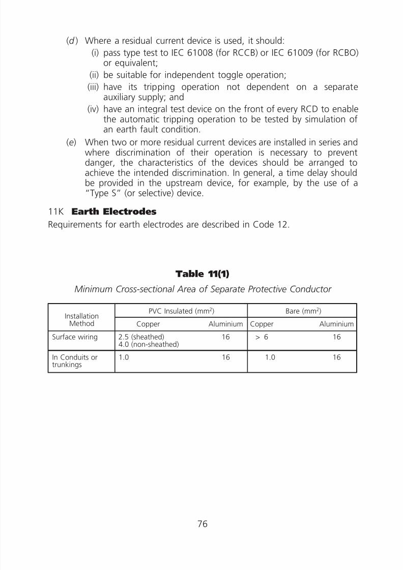
8/23/2019 Electricity Wiring
http://slidepdf.com/reader/full/electricity-wiring 76/337
(d ) Where a residual current device is used, it should:
(i) pass type test to IEC 61008 (for RCCB) or IEC 61009 (for RCBO)or equivalent;
(ii) be suitable for independent toggle operation;
(iii) have its tripping operation not dependent on a separateauxiliary supply; and
(iv) have an integral test device on the front of every RCD to enablethe automatic tripping operation to be tested by simulation ofan earth fault condition.
(e) When two or more residual current devices are installed in series andwhere discrimination of their operation is necessary to preventdanger, the characteristics of the devices should be arranged toachieve the intended discrimination. In general, a time delay should
be provided in the upstream device, for example, by the use of a“Type S” (or selective) device.
11K Earth Electrodes
Requirements for earth electrodes are described in Code 12.
Table 11(1)Minimum Cross-sectional Area of Separate Protective Conductor
InstallationMethod
PVC Insulated (mm2) Bare (mm2)
Copper Aluminium Copper Aluminium
Surface wiring 2.5 (sheathed) 164.0 (non-sheathed)
> 6 16
In Conduits ortrunkings
1.0 16 1.0 16
76

8/23/2019 Electricity Wiring
http://slidepdf.com/reader/full/electricity-wiring 77/337
Table 11(2)
(a) Minimum Cross-sectional Area of Protective Conductor in Relationto the Cross-sectional Area of Associated Phase Conductor
Minimum Cross-sectional Area of the
Corresponding Protective ConductorCross-sectional Area ofPhase Conductor If the Protective Conductor is of If the Protective Conductor is not
the Same Material as the Phase the Same Material as the Phase(S) Conductor Conductor
mm2 mm2 mm2
SՅ16 Sk
1S
——k
2
16ϽSՅ35 16k
116
——k
2
SϾ35 S—2
k1S——k
22
Note: For values of k1
and k2, please refer to tables 11(2)(b), (c ), (d ), (e) and ( f ).
(b) Values of k for insulated protective conductor not incorporated in a cableand not bunched with cables, or for separate bare protective conductor in
contact with cable covering but not bunched with cables where the
assumed initial temperature is 30°C
Material of conductor
Insulation of protective conductor or cable covering
70°Cthermoplastic
90°Cthermoplastic
90°Cthermosetting
Copper
Aluminium
Steel
143/133*
95/88*
52
143/133*
95/88*
52
176
116
64
Assumed initial temperature
Final temperature
30°C
160°C/140°C*
30°C
160°C/140°C*
30°C
250°C
* Above 300mm2
77

8/23/2019 Electricity Wiring
http://slidepdf.com/reader/full/electricity-wiring 78/337
(c) Values of k for protective conductor incorporated in a cable or bunched with cables, where the assumed initial temperature is 70°C or greater
Material of conductor
Insulation material
70°C
thermoplastic
90°C
thermoplastic
90°C
thermosettingCopper
Aluminium
115/103*
76/68*
100/86*
66/57*
143
94
Assumed initial temperature
Final temperature
70°C
160°C/140°C*
90°C
160°C/140°C*
90°C
250°C
* Above 300mm2
(d) Values of k for protective conductor as a sheath or armour of a cable
Material of conductor
Insulation material
70°Cthermoplastic
90°Cthermoplastic
90°Cthermosetting
Aluminium
Steel
Lead
93
51
26
85
46
23
85
46
23Assumed initial temperature
Final temperature
60°C
200°C
80°C
200°C
80°C
200°C
(e) Values of k for steel conduit, ducting and trunkingas the protective conductor
Material of protective conductor
Insulation material
70°Cthermoplastic
90°Cthermoplastic
90°Cthermosetting
Steel conduit, ducting and trunking 47 44 58
Assumed initial temperature
Final temperature
50°C
160°C
60°C
160°C
60°C
250°C
78

8/23/2019 Electricity Wiring
http://slidepdf.com/reader/full/electricity-wiring 79/337
(f) Values of k for bare conductor where there is no risk of damage to any neighbouring material by the temperatures indicated
Material of conductor
Conditions
Visible and in
restricted areas
Normal conditions Fire risk
Copper
Aluminium
Steel
228
125
82
159
105
58
138
91
50
Assumed initial temperature
Final temperature
Copper conductors
Aluminium conductors
Steel conductors
30°C
500°C
300°C
500°C
30°C
200°C
200°C
200°C
30°C
150°C
150°C
150°C
Table 11(3)
Minimum Cross-sectional Area of Protective Conductor forCircuits Protected by HBC Fuses to BS88 Part 2
Fuse Rating (Amp) 6 10 16 20 32 50 63 80 100 160 200 250 315 400
Minimumcross-sectionalarea (sq. mm)of protectiveconductor for5 sec.disconnection
Copper 1 1 1 1.5 2.5 4 6 10 10 16 25 25 35 50
Aluminium 16 16 16 16 16 16 16 16 16 25 35 50 50 70
Minimumcross-sectionalarea (sq. mm)of protectiveconductor for0.4 sec.disconnection
Copper 1 1 1 1 1 2.5
79

8/23/2019 Electricity Wiring
http://slidepdf.com/reader/full/electricity-wiring 80/337
0 Ͻ0.03
0
0.00ഛ
.000
00
00
00
00
.00
.00
0
0
Table 11(4)
Minimum Cross-sectional Area of Protective Conductor forCircuits Protected by HBC Fuses to BS1361
Fuse Rating (Amp) 5 15 20 30 45 60 80 100
Minimum cross-sectionalarea (sq. mm) ofprotective conductor for5 sec. disconnection
Copper 1 1 1.5 2.5 4 10 10 16
Aluminium 16 16 16 16 16 16 16 25
Minimum cross-sectionalarea (sq. mm) ofprotective conductor for0.4 sec. disconnection
Copper 1 1 1 1 2.5
Table 11(5)
Minimum Cross-sectional Area of Protective Conductor for Circuits Protected by Miniature Circuit Breaker Type 1 & 2 to BS 3871 or Equivalent
Earth Fault LoopImpedance Zs (ohm)
Minimum Cross-sectional Area of Protective Conductor (mm2)for 5 Sec. and 0.4 Sec. Disconnection
Copper Aluminium
0.2 ഛZs
0.13ഛZsϽ0.2
0.08ഛZsϽ0.13
0.05ഛZsϽ0.08
0.03ഛZsϽ0.05
0.02ഛZsϽ0.03
ZsϽ0.02
1
1.5
2.5
4.0
6.0
10
16
16
16
16
16
16
16
25
Table 11(6)
Minimum Cross-sectional Area of Protective Conductor forCircuit Protected by Miniature Circuit Breaker (MCB) Type 3,
Type B & Type C to IEC 60898 or Equivalent
MCB Rating (Amp) 5 10 15 20 30 50 60 80 100
Minimum cross-sectionalarea (sq. mm) of
protective conductor for5 sec. disconnection
Copper 1 1.5 2.5 2.5 4 10 10 16 16
Aluminium 16 16 16 16 16 16 16 16 25
Minimum cross-sectionalarea (sq. mm) ofprotective conductor for0.4 sec. disconnection
(Please refer to Table 11(5))
80

8/23/2019 Electricity Wiring
http://slidepdf.com/reader/full/electricity-wiring 81/337
.0 . . . . . .
0
Table 11(7)
Minimum Cross-sectional Area of Protective Conductor for Circuit Protected by Moulded Case Circuit Breaker (MCCB)
to IEC 60947-2 or Equivalent for 5 Sec. Disconnection
MCCB Rating (Amp) 30 50 60 100 150 200 250 300 400
Minimum cross-sectionalarea (sq. mm) ofprotective conductor
Copper 6 10 10 10 10 10 10 16 16
Aluminium 16 16 16 16 16 16 16 25 25
Table 11(8)
Maximum Earth Fault Loop Impedance for 0.4 Sec. Disconnection when
the Circuit is Protected by General Purpose (gG) Fuses toBS88 Parts 2 and 6 with Nominal Voltage Uo 220V
Fuse Rating (Amp) 6 10 16 20 32 50
Zs (ohm) 8.1 4.9 2.6 1.7 1.0 0.58
Table 11(9)
Maximum Earth Fault Loop Impedance for 0.4 Sec. Disconnectionwhen the Circuit is Protected by Fuses to BS1361
or Equivalent with Nominal Voltage Uo 220V
Fuse Rating (Amp) 5 15 20 30 45
Zs (ohm) 10 3.1 1.6 1.1 0.55
Table 11(10)
Maximum Earth Fault Loop Impedance for 0.2 Sec., 0.4 Sec. and 5 Sec.Disconnection when the Circuit is Protected by Miniature Circuit Breaker (MCB) to IEC 60898 or Equivalent or RCBO to IEC 61009
with Nominal Voltage Uo 220V
Rating (Amp) 6 10 16 20 32 40 50 63 80 100
Zs (ohm) for 7.33 4.4 2.75 2.2 1.38 1.1 0.88 0.70 0.55 0.44type B MCBand RCBO
Zs (ohm) for 3.67 2.2 1.38 1.1 0.69 0.55 0.44 0.35 0.28 0.22type C MCBand RCBO
8181

8/23/2019 Electricity Wiring
http://slidepdf.com/reader/full/electricity-wiring 82/337
0 .0 .0 .0 . . .0 .0 .
0 0
.0 .0 .0 .0 . . . . .
0
00 00 0 0 0 0 0 0
0 0 0 0
Table 11(11)
Maximum Earth Fault Loop Impedance for 5 Sec. Disconnectionwhen a Circuit is Protected by General Purpose (gG) Fuses
to BS88 Parts 2 and 6 or Equivalent with Nominal Voltage Uo 220V
Fuse Rating(Amp) 6 10 16 20 32 50 60 80 100 160 200 250 315 400
Zs (ohm) 12.9 7.1 4.0 2.8 1.8 1.0 0.83 0.55 0.40 0.24 0.18 0.15 0.1 0.09
Table 11(12)
Maximum Earth Fault Loop Impedance for 5 Sec. Disconnectionwhen a Circuit is Protected by House-service Fuse to
BS1361 or equivalent with Nominal Voltage Uo 220V
Fuse Rating (Amp) 5 15 20 30 45 60 80 100
Zs (ohm) 15.7 4.8 2.7 1.8 0.92 0.67 0.48 0.35
Table 11(13)
Maximum Earth Fault Loop Impedance for 5 Sec. Disconnection
when a Circuit is Protected by a Moulded Case Circuit Breaker (MCCB)to IEC 60947-2 or Equivalent with Nominal Voltage Uo 220V
MCCB Rating (Amp) 30 50 60 100 150 200 250 300 400
MCCB Non-adjustable Zs (ohm) 0.56 0.44 0.42 0.125 0.09 0.07 0.06 0.05 0.04
MCCB Adjustable Zs(ohm)
Magnetic setting= ‘LO’
— — — — — — 0.1 0.08 0.06
Magnetic setting= ‘HI’ — — — — — — 0.05 0.04 0.03
Note: 1. Tables 11(8)–11(13) are based on nominal voltage to earth Uo at 220V. If the voltage
is 200V the corresponding value of the earth fault loop impedance shall be obtained bymultiplying the factor 0.91.2. Table 11(13) is for reference only. Please refer to the manufacturer’s data.
Table 11(14)
Maximum Earth Fault Loop Impedancewhen a Circuit is Protected by a Residual Current Device
Rated ResidualOperating Current (mA) 5 10 20 30 100 300 500 1000 2000
Zs (ohm) 10000 5000 2500 1667 500 167 100 50 25
82

8/23/2019 Electricity Wiring
http://slidepdf.com/reader/full/electricity-wiring 83/337
83

8/23/2019 Electricity Wiring
http://slidepdf.com/reader/full/electricity-wiring 84/337
Code 12 EARTHING ARRANGEMENT
12A General
12B Bonding Connections to the Point of Supply
(1) Supply by transformer
(2) Supply by underground cable
(3) To satisfy regulation 11 with bonding disconnected
(4) Application of Code 12B
12C Earth Electrode
(1) Types of earth electrodes
(2) Rod electrode
(3) Tape electrode
(4) Plate electrode
(5) Installation of earth electrodes
84
8/23/2019 Electricity Wiring
http://slidepdf.com/reader/full/electricity-wiring 85/337
Code 12 EARTHING ARRANGEMENT
12A General
(a) An installation should have an earthing arrangement such that:
(i) the installation is protected by its own earth electrode(s); and(ii) the main earthing terminal of the installation is bonded to the
earthing facilities that are available from the electricity supplier (asdescribed in Code 12B below).
(b) For those installations connected to supplies before the commencementof the Wiring Regulations (1 June 1992), they should have one or anycombination of the following earthing arrangements:
(i) the installation is protected by its own earth electrode(s);
(ii) the main earthing terminal of the installation is connected to theearthing facilities provided by the electricity supplier; or
(iii) the main earthing terminal of the installation is connected to acommon earthing conductor which is connected to earthelectrode(s) or the earthing facilities provided by the electricitysupplier.
12B Bonding Connections to the Point of Supply
(1) Supply by transformer Where the supply is taken directly from the electricity supplier’stransformer(s) within the premises in which the installation is situated,the main earthing terminal of the installation should be bonded by aconductor or through a common conductor to a bonding terminalprovided by the electricity supplier at the point of supply, for example,near the transit block or the main cable terminations on the incomingcircuit breakers.
(2) Supply by underground cable
Where the supply is taken from the electricity supplier’s undergroundcable(s) having exposed conductive parts, such as metallic cable endbox,metallic cable glands, cable armour or metallic sheath etc., at the cabletermination at the point of supply, the main earthing terminal of theinstallation should be bonded to these exposed conductive parts viabonding terminal(s) provided by the electricity supplier.
(3) To satisfy regulation 11 with bonding disconnected
Where bonding referred to in subparagraphs (1) and (2) above is used toprevent the rise of a dangerous earth potential, the installation shouldsatisfy all the requirements of regulation 11 of the Wiring Regulations
85

8/23/2019 Electricity Wiring
http://slidepdf.com/reader/full/electricity-wiring 86/337
(Earth leakage and earth fault currents) even if the bonding isdisconnected.
(4) Application of Code 12B
Code 12B applies only to an installation that is completed or substantiallyaltered on or after the commencement of the Wiring Regulations (1 June1992).
12C Earth Electrode
(1) Types of earth electrodes
(a) The material used and the construction of the earth electrodesshould be such as to withstand damage due to corrosion. Thefollowing types of earth electrodes are acceptable:
(i) earth rods or pipes;(ii) earth tapes or wires;
(iii) earth plates;
(iv) metallic reinforcement of concrete, including sheet piles.
(b) the metalwork of gas and water services should not be used as anearth electrode.
(2) Rod electrode
(a) The overall diameter of copper rod electrode should not be less than12.5 mm.
(b) The overall diameter of a rod electrode of materials such as stainlesssteel and galvanised steel should not be less than 16 mm.
(c ) A hardened steel point may be fitted to the penetrating end of therod electrode.
(d ) Additional lengths of rod, whenever required, should each beconnected together by a coupling.
(e) For installation of additional rods, it is recommended that a mutualseparation of 3.5 m or a distance greater than twice the drivenlength should be maintained. All rods thus installed should beconnected together by means of earthing conductors of adequatesize enclosed in PVC ducts and laid at a minimum depth of 600 mmbelow the ground surface.
(3) Tape electrode
(a) Tape electrodes should be copper strip having a cross-section of not
less than 25 mm×
3 mm.(b) In case where several tapes are required for connection in parallel to
achieve a low earthing resistance, they may be installed in parallellines or they may radiate from a point.
86

8/23/2019 Electricity Wiring
http://slidepdf.com/reader/full/electricity-wiring 87/337
(4) Plate electrode
Plate electrodes should be of copper not less than 3 mm in thickness andhaving a maximum dimension of 1 200 mm × 1 200 mm.
(5) Installation of earth electrode
Installation of earth electrode should comply with the Electricity SupplyLines (Protection) Regulation as appropriate.
87

8/23/2019 Electricity Wiring
http://slidepdf.com/reader/full/electricity-wiring 88/337
Code 13 CONDUCTORS, JOINTS ANDCONNECTIONS
13A Selection and Sizing of Cable Conductors
(1) General(2) Factors to be considered in sizing of cable conductors
(3) Method of sizing cable conductors
(4) Typical sizes of cable conductor used in general installations
13B Basic Protection
(1) Protection by electrical insulation
(2) Protection by other means
13C Joints and Connections
13D Other Requirements of Cables
(1) Voltage grading of cables for low voltage application
(2) Identification of cable cores
(3) Identification of cables buried direct in ground
88
8/23/2019 Electricity Wiring
http://slidepdf.com/reader/full/electricity-wiring 89/337
Code 13 CONDUCTORS, JOINTS ANDCONNECTIONS
13A Selection and Sizing of Cable Conductors
(1) General
A conductor should have a current carrying capacity not less than themaximum current demand it normally carries, be capable of withstandingthe prospective fault current, and suitable for operation in theenvironment and at the design voltage of the installation.
(2) Factors to be considered in sizing of cable conductors
In general, sizing of cable conductors should take into account thefollowing factors:
(a) the conductor material;
(b) the insulating material;
(c ) the ambient temperature in which the cable is installed;
(d ) the method of installation;
(e) whether or not the cable is affected by thermal insulating material;
( f ) the use and type of protective device;
( g) the voltage drop from the origin of the circuit to the load; and
(h) for Category 1 circuits, live conductors should have a cross-sectionalarea:
(i) not less than 1.5 mm2 for surface wiring using PVC insulatedPVC sheath copper cables;
(ii) not less than 1.0 mm2 for single core PVC insulated copper
cables installed in conduit, duct, ducting or trunking;(iii) not less than 16 mm2 for aluminium conductors;
(iv) not less than 0.5 mm2 for flexible cables and flexible cords.
(3) Method of sizing cable conductors
(a) In determining the size of cable conductors to be used, the stepsemployed, in general, are as follows:
(i) Determine the design current of the circuit under consideration.
(ii) Choose a suitable overcurrent protective device (refer toCode 9).
89
8/23/2019 Electricity Wiring
http://slidepdf.com/reader/full/electricity-wiring 90/337
(iii) Determine the current carrying capacity of the conductorsrequired by applying suitable correction factors to the nominalsetting or current rating of the overcurrent protective device asdivisors.
Typical correction factors for ambient temperature, grouping,
thermal insulation and type of protective device are given inAppendix 5.
(iv) Choose suitable size of the conductors according to the currentcarrying capacity required. Appendix 6 gives the current carryingcapacities for various copper conductor sizes of PVC/XLPEinsulated cables according to their installation methods. Forother types of cables, reference should be made to BS 7671 orIEC 60364.
(v) The resulting voltage drop in the circuit should be checked sothat under normal service conditions the voltage at theterminals of any fixed current using equipment should begreater than the lower limit corresponding to recognisedstandards relevant to the equipment.
Where the fixed current using equipment concerned is not thesubject of a recognised standard, the voltage at the terminalsshould be such as not to impair the safe function of thatequipment.
The above requirements are deemed to be satisfied if thevoltage drop between the origin of the installation (usually thesupply terminals) and the fixed current using equipment doesnot exceed 4% of the nominal voltage of the supply.
A greater voltage drop may be accepted for a motor duringstarting periods and for other equipment with high inrushcurrent provided that voltage variations are within the limitsspecified in the relevant recognised standards for the equipmentor, in the absence of a recognised standard, in accordance with
the manufacturer’s recommendations.Table in Appendix 6 also gives the values of voltage drop causedby one ampere for a metre run of PVC/XLPE insulated cableswith copper conductors.
If the voltage drop so determined is unsatisfactory, a conductorof larger size should be chosen accordingly.
(b) To illustrate the steps used in sizing cable conductors, an example isgiven in Appendix 12.
(4) Typical sizes of cable conductor used in general installations
For general installations under the conditions listed below, the sizes ofcopper conductor in compliance with Table 13(1) are generallyacceptable:
90

8/23/2019 Electricity Wiring
http://slidepdf.com/reader/full/electricity-wiring 91/337
(a) the ambient temperature does not exceed 35°C;
(b) no more than one circuit of single core cables or one multicore cableare to be grouped together;
(c ) for cables clipped direct on surface, the spacing between groups of
single core cables or multicore cables is not less than twice thediameter of the largest cable in the adjacent group of cables;
(d ) the protective device is not a semi-enclosed fuse; and
(e) the cables are not in contact with any thermal insulation.
13B Basic Protection
(1) Protection by electrical insulation
(a) Live conductors should be completely covered with insulation which:
(i) is durably withstanding the mechanical, electrical, thermal andchemical stresses to which it may be subjected in service; and
(ii) can only be removed by destruction.
(b) Where insulation is applied during the erection of the installation,the quality of the insulation should be verified by tests equivalent tothose specified in recognised standards for similar type-testedequipment.
(c ) Non-impregnated paper, asbestos, fabric, wood or press-hempshould not be used for insulating purposes.
(d ) Where insulating tapes are permitted to be used in low voltageinstallations, they should have a minimum thickness of 0.21 mm.
(2) Protection by other means
Other means of basic protection as stipulated in IEC 60364 or BS7671 areacceptable.
13C Joints and Connections
(a) Every connection at a cable termination or joint should:
(i) be mechanically and electrically sound;
(ii) be protected against moisture, mechanical damage and anyvibration liable to occur;
(iii) not impose any appreciable mechanical strain on the fixings of the
connection;(iv) not cause any harmful damage to the cable conductor;
(v) be appropriate to the size and type of conductors with which theyare to be used; and
91

8/23/2019 Electricity Wiring
http://slidepdf.com/reader/full/electricity-wiring 92/337
(vi) be suitably insulated for the voltage of the circuits in which they aresituated.
(b) No strand of a stranded conductor in a cable core should be cut away inmaking a cable joint or termination.
(c ) Joints in non-flexible cables should be made by soldering, brazing,welding, or mechanical clamps, or be of the compression type. Allmechanical clamps and compression type sockets should securely retainall the wires of the conductor.
(d ) Joints in flexible cable or flexible cord should be made by usingappropriate cable couplers.
(e) Terminations of mineral insulated cables should be made with properaccessories and tools as recommended by the manufacturers.
(f ) Cable glands should securely retain without damaging the outer sheathor the armour of the cables.
( g) Other details relating to the workmanship of cable joint and terminationare described in Code 25D.
(h) Except for the following, every connection and joint should be accessiblefor inspection, testing and maintenance:
(i) a compound filled or encapsulated joint;
(ii) a connection between a cold tail and a heating element (e.g. a
ceiling and floor heating system, a pipe trace-heating system); and(iii) a joint made by welding, soldering, brazing or compression tool.
13D Other Requirements of Cables
(1) Voltage grading of cables for low voltage application
(a) PVC insulated non-sheathed cables to BS6004 and BS6007 shouldbe 450/750V grade.
(b) PVC insulated, PVC sheathed cables up to 35 mm2 to BS6004 shouldbe 300/500V grade. For cables greater than 50 mm2 to BS6346,voltage grade should be 600/1000V.
(c ) PVC insulated, PVC sheathed armoured cables of any size to BS6346should be 600/1000V grade.
(d ) XLPE insulated, non-sheathed or PVC sheathed cables to BS7211should be 450/750V grade and to BS 5467 should be 600/1000Vgrade.
(e) XLPE insulated, PVC sheathed armoured cables to BS5467 andBS 6724 should be 600/1000V grade.
92
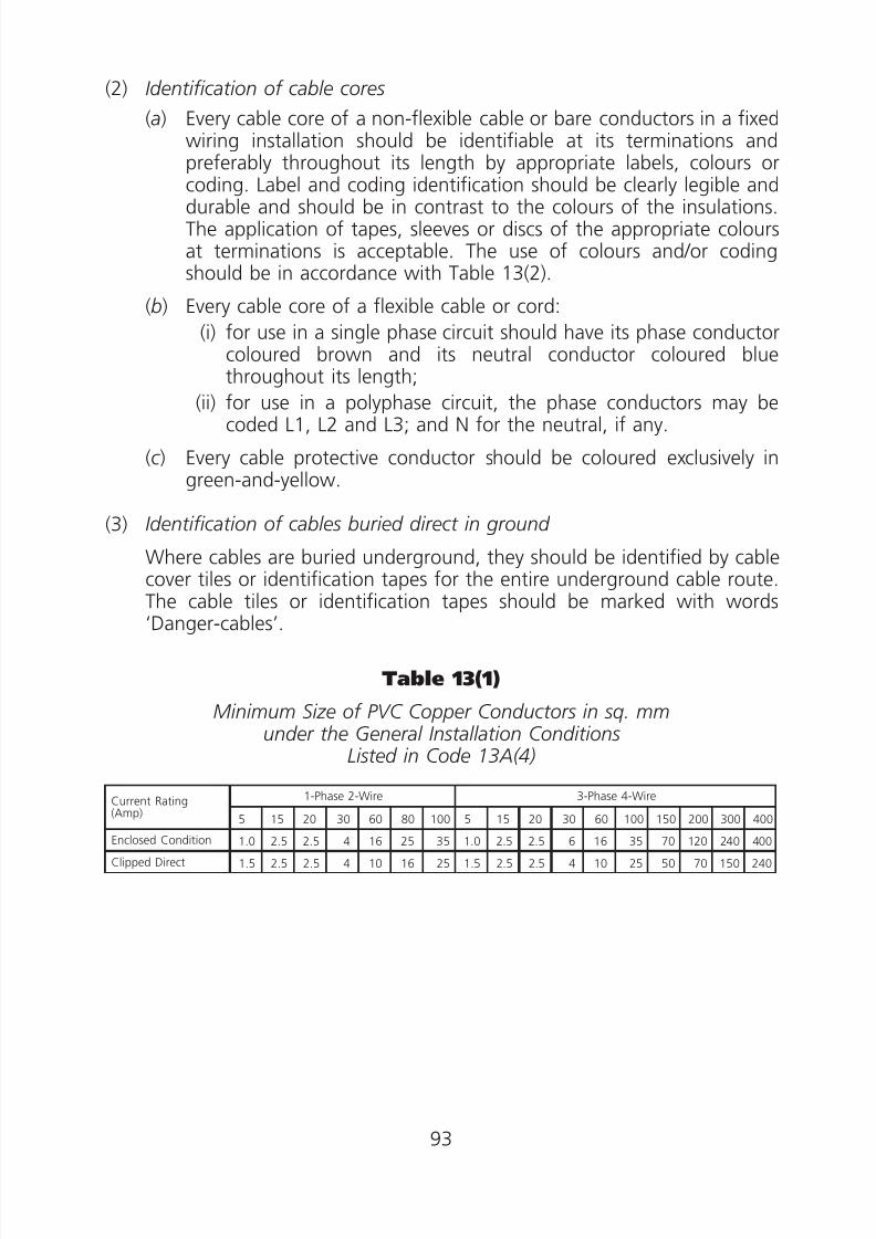
8/23/2019 Electricity Wiring
http://slidepdf.com/reader/full/electricity-wiring 93/337
.0 . . .0 . .
0 0 0 0 0
0 0 0 0 0 0
(2) Identification of cable cores
(a) Every cable core of a non-flexible cable or bare conductors in a fixedwiring installation should be identifiable at its terminations andpreferably throughout its length by appropriate labels, colours orcoding. Label and coding identification should be clearly legible and
durable and should be in contrast to the colours of the insulations.The application of tapes, sleeves or discs of the appropriate coloursat terminations is acceptable. The use of colours and/or codingshould be in accordance with Table 13(2).
(b) Every cable core of a flexible cable or cord:
(i) for use in a single phase circuit should have its phase conductorcoloured brown and its neutral conductor coloured bluethroughout its length;
(ii) for use in a polyphase circuit, the phase conductors may becoded L1, L2 and L3; and N for the neutral, if any.
(c ) Every cable protective conductor should be coloured exclusively ingreen-and-yellow.
(3) Identification of cables buried direct in ground
Where cables are buried underground, they should be identified by cablecover tiles or identification tapes for the entire underground cable route.
The cable tiles or identification tapes should be marked with words‘Danger-cables’.
Table 13(1)
Minimum Size of PVC Copper Conductors in sq. mmunder the General Installation Conditions
Listed in Code 13A(4)
Current Rating(Amp)
1-Phase 2-Wire 3-Phase 4-Wire
5 15 20 30 60 80 100 5 15 20 30 60 100 150 200 300 400
Enclosed Condition 1.0 2.5 2.5 4 16 25 35 1.0 2.5 2.5 6 16 35 70 120 240 400
Clipped Direct 1.5 2.5 2.5 4 10 16 25 1.5 2.5 2.5 4 10 25 50 70 150 240
93

8/23/2019 Electricity Wiring
http://slidepdf.com/reader/full/electricity-wiring 94/337
Table 13(2)
Identification of Non-flexible Cables andBare Conductors for Fixed Wiring
Function
Colour
Old Colour New Colour Coding
Phase of single phase circuit Red (or Yellow orWhite or Blue)
Brown L
Phase 1 of 3-phase circuit Red Brown L1
Phase 2 of 3-phase circuit Yellow (or White) Black L2
Phase 3 of 3-phase circuit Blue Grey L3
Neutral Black Blue N
Protective conductor Green-and-yellow Green-and-yellow —
(Note: The new colour code may be used for those electrical installation works commencing on-site on or after 1 July 2007. For installation works commencing on-site from 1 July 2007to 30 June 2009 (i.e. the 2-year grace period), either the new or the old colour code, butnot both, can be used. For installation works commencing on-site on or after1 July 2009, only the new colour code should be used.)
94

8/23/2019 Electricity Wiring
http://slidepdf.com/reader/full/electricity-wiring 95/337
Code 14 WIRING INSTALLATION ENCLOSURE
14A General Requirements
(1) Enclosures as protective conductors
(2) Support of enclosures
(3) Fire barrier
14B Steel Conduit System
(1) Construction
(2) Installation
14C Steel Trunking System
(1) Construction
(2) Installation
14D Plastic or PVC Conduit or Trunking
(1) Construction
(2) Installation
14E Cable Capacity of Enclosures
(1) General requirements
(2) Determination of cable capacities
14F Enclosures of Busbar Trunking System and Powertrack System
14G Workmanship
95
8/23/2019 Electricity Wiring
http://slidepdf.com/reader/full/electricity-wiring 96/337
Code 14 WIRING INSTALLATION ENCLOSURE
14A General Requirements
(1) Enclosures as protective conductors
(a) Metallic enclosures for cables, busbar trunking and switchgear andcontrolgear assemblies, where used as protective conductors should:
(i) have a cross-sectional area not less than that determined fromthe application of Code 11C(2)(e) or verified by test inaccordance with IEC 60439-1 or equivalent;
(ii) have an electrical continuity achieved and maintained to affordprotection against mechanical, chemical or electrochemicaldeterioration; and
(iii) permit the connection of other protective conductors at everypredetermined tap-off point.
(b) Where conduit, trunking or ducting are used as a protectiveconductor, the earthing terminal of each accessory should beconnected by a separate protective conductor of adequate size to anearthing terminal incorporated in the associated box or enclosure.
(2) Support of enclosures
All conduit, ducting and trunking installations should be properlysupported and of a type suitable for any risk of mechanical damage towhich they may be liable in normal conditions of service or adequatelyprotected against such damage.
(3) Fire barrier
(a) Where conduit, duct, ducting or trunking pass through fire-resistantstructural elements such as floors and walls designated as firebarriers, the opening made should be sealed according to the fireresistance requirements of BS 476:Part 20 or equivalent.
(b) Where cables, conduits or conductors are installed in channel, duct,ducting, trunking or shaft which pass through fire-resistant structuralelements, suitable internal fire-resistant barriers should be providedto prevent the spread of fire.
14B Steel Conduit System
(1) Construction
(a) Steel conduits and fitting with metric thread, except flexible conduits,should be of heavy gauge, longitudinally welded type and comply withBS4568, BS EN 60423, BS EN 61386, IEC 60423, IEC 61386 orequivalent. The nominal minimum outside diameter of any rigid conduitto be used should be 16 mm with a minimum wall thickness of 1.4 mm.
96
8/23/2019 Electricity Wiring
http://slidepdf.com/reader/full/electricity-wiring 97/337
(b) Flexible steel conduits should comply with BS EN 61386, IEC 61386or equivalent. In addition, where flexible conduits are exposed toweather or in damp situations, the conduits should be of the metallictype with PVC oversheath.
(c ) All steel conduits, conduit fittings and the associated metallic boxesfor the enclosure of electrical accessories should be protectedagainst corrosion on both the inside and outside surfaces.
(2) Installation
(a) The steel conduit installation should be made mechanically andelectrically continuous throughout, be effectively earthed andcomply with BS4568, BS EN 60423, BS EN 61386, IEC 60423, IEC61386 or equivalent.
(b) An adequate number of suitably sized adaptable boxes should beprovided in the conduit installation to enable cables to be drawn ineasily and without damage.
(c ) Flexible steel conduit should not be used as a protective conductorand it should have a separate circuit protective conductor ofadequate size for earth continuity.
(d ) Conduits should be installed so as to prevent accumulation ofcondensed moisture or water in any part of the installations.
14C Steel Trunking System
(1) Construction
(a) Steel trunking and fittings should be fabricated with sheet steelhaving a minimum thickness as indicated in Table 14(1) and shouldcomply with the requirements specified in BS4678: Part 1 orequivalent.
(b) Underfloor trunking should be compatible to the requirements laiddown in BS4678: Part 2 or equivalent and should be fabricated withsheet steel of:
(i) not less than 1.2 mm thickness for compartment width up toand including 100 mm;
(ii) not less than 1.6 mm thickness for compartment width over100 mm; and
(iii) not less than 1.0 mm thickness for the partitions and connectormaterial.
(c ) Steel trunking installations should be constructed using manufacturer’s standard fittings such as tee or angle pieces, connectorsetc., throughout as far as practicable.
(d ) All steel trunking and fittings should be protected against corrosion.
97
8/23/2019 Electricity Wiring
http://slidepdf.com/reader/full/electricity-wiring 98/337
(2) Installation
(a) The steel trunking installation should be made mechanically andelectrically continuous throughout, and be effectively earthed.
(b) Electrical continuity should be achieved by means of connecting a
protective conductor (e.g. copper tape) of adequate size across thetwo adjacent ends of the trunking.
(c ) Every entry to the trunking installation should be so placed as toprevent and/or to be protected against the ingress of water.
14D Plastic or PVC Conduit or Trunking
(1) Construction
(a) Rigid plastic or PVC conduits and conduit fittings should be of suchstrength to withstand the stress under the installed conditions. Theyshould comply with BS4607: Part 1 and 2, BS EN 61386, IEC 61386or equivalent.
(b) Pliable conduits should be made of self-extinguishing plastic materialand comply with BS4607: Part 3 or equivalent.
(c ) Adaptable boxes and boxes for the enclosure of electrical accessoriesthat are made of insulating materials should comply with BS4662 orequivalent and have a minimum wall thickness of 2 mm.
(2) Installation
(a) Plastic or PVC conduit or trunking systems should only be installedwhere they are suitable for the extremes of ambient temperature towhich they are likely to be subject under the installed conditions.Rigid PVC conduits or trunking should not be used where the normal
working temperature of the installation may exceed 60°C.
(b) Any exposed conductive parts of a PVC or plastic conduit system ortrunking should be connected to earth by protective conductor ofadequate size for maintaining an effective continuity. Where theplastic or PVC conduit system is made between metal conduitsystem, the earthing connection should be made at the steelconduit/trunking and at the nearest boxes with proper terminals.
(c ) The method of support and installation for rigid PVC conduits should
allow for the longitudinal expansion and contraction of the conduitswhich may occur with variation of temperature under normaloperating conditions.
98
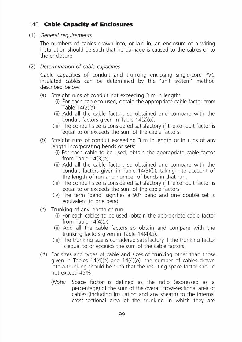
8/23/2019 Electricity Wiring
http://slidepdf.com/reader/full/electricity-wiring 99/337
14E Cable Capacity of Enclosures
(1) General requirements
The numbers of cables drawn into, or laid in, an enclosure of a wiringinstallation should be such that no damage is caused to the cables or to
the enclosure.
(2) Determination of cable capacities
Cable capacities of conduit and trunking enclosing single-core PVCinsulated cables can be determined by the ‘unit system’ methoddescribed below:
(a) Straight runs of conduit not exceeding 3 m in length:(i) For each cable to used, obtain the appropriate cable factor from
Table 14(2)(a).(ii) Add all the cable factors so obtained and compare with the
conduit factors given in Table 14(2)(b).(iii) The conduit size is considered satisfactory if the conduit factor is
equal to or exceeds the sum of the cable factors.
(b) Straight runs of conduit exceeding 3 m in length or in runs of anylength incorporating bends or sets:
(i) For each cable to be used, obtain the appropriate cable factorfrom Table 14(3)(a).
(ii) Add all the cable factors so obtained and compare with theconduit factors given in Table 14(3)(b), taking into account ofthe length of run and number of bends in that run.
(iii) The conduit size is considered satisfactory if the conduit factor isequal to or exceeds the sum of the cable factors.
(iv) The term ‘bend’ signifies a 90° bend and one double set isequivalent to one bend.
(c ) Trunking of any length of run:(i) For each cables to be used, obtain the appropriate cable factor
from Table 14(4)(a).(ii) Add all the cable factors so obtain and compare with the
trunking factors given in Table 14(4)(b).(iii) The trunking size is considered satisfactory if the trunking factor
is equal to or exceeds the sum of the cable factors.
(d ) For sizes and types of cable and sizes of trunking other than thosegiven in Tables 14(4)(a) and 14(4)(b), the number of cables drawninto a trunking should be such that the resulting space factor shouldnot exceed 45%.
(Note: Space factor is defined as the ratio (expressed as apercentage) of the sum of the overall cross-sectional area ofcables (including insulation and any sheath) to the internalcross-sectional area of the trunking in which they are
99
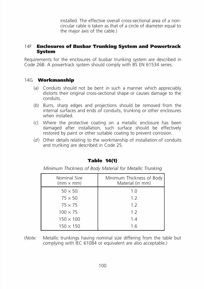
8/23/2019 Electricity Wiring
http://slidepdf.com/reader/full/electricity-wiring 100/337
0 0
0 0
0 0
0
installed. The effective overall cross-sectional area of a non-circular cable is taken as that of a circle of diameter equal tothe major axis of the cable.)
14F Enclosures of Busbar Trunking System and PowertrackSystem
Requirements for the enclosures of busbar trunking system are described inCode 26B. A powertrack system should comply with BS EN 61534 series.
14G Workmanship
(a) Conduits should not be bent in such a manner which appreciably
distorts their original cross-sectional shape or causes damage to theconduits.
(b) Burrs, sharp edges and projections should be removed from theinternal surfaces and ends of conduits, trunking or other enclosureswhen installed.
(c ) Where the protective coating on a metallic enclosure has beendamaged after installation, such surface should be effectivelyrestored by paint or other suitable coating to prevent corrosion.
(d ) Other details relating to the workmanship of installation of conduitsand trunking are described in Code 25.
Table 14(1)
Minimum Thickness of Body Material for Metallic Trunking
Nominal Size(mm × mm)
Minimum Thickness of BodyMaterial (in mm)
50 × 50
75 × 50
75 × 75
100 × 75
150 × 100
150 × 150
1.0
1.2
1.2
1.2
1.4
1.6
(Note: Metallic trunkings having nominal size differing from the table butcomplying with IEC 61084 or equivalent are also acceptable.)
100

8/23/2019 Electricity Wiring
http://slidepdf.com/reader/full/electricity-wiring 101/337
11
11
11
11
Table 14(2)
Cable Factors and Conduit Factors for Straight Runs ofConduit not Exceeding 3 m in Length
(a) Cable Factor
Type of Conductor
ConductorCross-Sectional
Area (mm2) Factor
Solid
1 22
1.5 27
2.5 39
Stranded
1.5 31
2.5 43
4 58
6 88
10 146
(b) Conduit Factor
Conduit Diameter(mm) Factor
16 290
20 460
25 800
32 1 400
101

8/23/2019 Electricity Wiring
http://slidepdf.com/reader/full/electricity-wiring 102/337
.0
0.
0.
.
Table 14(3)
Cable Factors and Conduit Factors for Conduit Exceeding 3 m in length or inRuns Incorporating Bends or Sets
(a) Cable Factor
Type of Conductor
ConductorCross-Sectional
Area (mm2) Factor
1 16
1.5 22
2.5 30
Solid or stranded 4 43
6 58
10 105
(b) Conduit Factor
Length ofRun (m)
Conduit Diameter (mm)
16 20 25 32 16 20 25 32 16 20 25 32 16 20 25 32 16 20 25 32
Straight One bend Two bends Three bends Four bends
1
Covered by Tables14(2) (a) and (b)
188 303 543 947 177 286 514 900 158 256 463 818 130 213 388 692
1.5 182 294 528 923 167 270 487 857 143 233 422 750 111 182 333 600
2 177 286 514 900 158 256 463 818 130 213 388 692 97 159 292 529
2.5 171 278 500 878 150 244 442 783 120 196 358 643 86 141 260 474
3 167 270 487 857 143 233 422 750 111 182 333 600
3.5 179 290 521 911 162 263 475 837 136 222 404 720 103 169 311 563
4 177 286 514 900 158 256 463 818 130 213 388 692 97 159 292 529
4.5 174 282 507 889 154 250 452 800 125 204 373 667 91 149 275 500
5 171 278 500 878 150 244 442 783 120 196 358 643 86 141 260 474
6 167 270 487 857 143 233 422 750 111 182 333 600
7 162 263 475 837 136 222 404 720 103 169 311 563
8 158 256 463 818 130 213 388 692 97 159 292 529
9 154 250 452 800 125 204 373 667 91 149 275 500
10 150 244 442 783 120 196 358 643 86 141 260 474
102
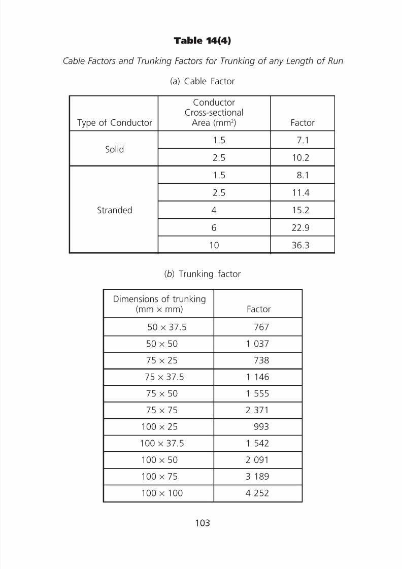
8/23/2019 Electricity Wiring
http://slidepdf.com/reader/full/electricity-wiring 103/337
11
11
11
11
000
0
0
00
0
0
0
0
Table 14(4)
Cable Factors and Trunking Factors for Trunking of any Length of Run
(a) Cable Factor
Type of Conductor
Solid
Stranded
ConductorCross-sectional
Area (mm2)
1.5
2.5
1.5
2.5
4
6
10
Factor
7.1
10.2
8.1
11.4
15.2
22.9
36.3
(b) Trunking factor
Dimensions of trunking(mm × mm) Factor
50 × 37.5 767
50 × 50 1 037
75 × 25 738
75 × 37.5 1 146
75 × 50 1 555
75 × 75 2 371
100 × 25 993
100 × 37.5 1 542
100 × 50 2 091100 × 75 3 189
100 × 100 4 252
103103

8/23/2019 Electricity Wiring
http://slidepdf.com/reader/full/electricity-wiring 104/337
Code 15 ADVERSE CONDITIONS INSTALLATION
15A Presence of Water (AD) or High Humidity (AB)*
(1) Construction of equipment
(2) Conductors and enclosures of wiring installations
(3) Switches and socket outlets
15B Ambient Temperature (AA)
(1) General
(2) Electrical insulations
(3) Conductors and cables
(4) Enclosures of wiring installations
(5) External heat sources
15C Presence of Corrosive or Polluting Substance (AF)
15D Installation Exposed to Fire or Explosion
(1) General
(2) Electrical equipment selection(3) Wiring systems
15E Impact (AG)
15F Vibration (AH)
15G Other Mechanical Stresses
* For codes of external influences, table 15(3) refers.
104

8/23/2019 Electricity Wiring
http://slidepdf.com/reader/full/electricity-wiring 105/337
Code 15 ADVERSE CONDITIONS INSTALLATION
15A Presence of Water (AD) or High Humidity (AB)
(1) Construction of equipment
(a) A wiring system should be selected and erected so that no damageis caused by high humidity, high condensation or ingress of waterduring installation, use and maintenance.
(b) Where water may collect or condensation may form in a wiringsystem, provision should be made for its harmless escape throughsuitably located drainage points.
(c ) Where a wiring system may be subjected to waves (AD6), protectionagainst mechanical damage should be afforded by one or more of
the methods given in Codes 15E, 15F and 15G.
(2) Conductors and enclosures of wiring installations
(a) Copperclad aluminium conductors should not be used.
(b) All exposed conductors and insulations at terminations and joints ofcables that are insulated with impregnated paper should be suitablysealed against ingress of moisture.
(c ) Every joint in a cable should be suitably insulated and protectedagainst the effect of moisture or water.
(d ) Overall PVC covering should be provided for mineral insulated cable.
(e) The ends of mineral insulated cables should be suitably sealed withpurposely designed terminations and sealing material, havingadequate insulating and moisture proofing properties throughoutthe range of temperatures to which they may be subjected inservice. The mineral insulation of the cables should be thoroughlydried before the sealing material is applied.
(f ) Every entry to finished ducts, ducting or trunking should be placedso as to prevent the ingress of water, or be protected against suchingress.
( g) All metal sheath and armour of cables, metal conduits, ducts,ductings, trunkings, clips and their fixings, should be of corrosionresisting material or finish and should not be placed in direct contactwith other dissimilar metals which they are liable to set upelectrolytic action.
In particular, contact between bare aluminium sheaths or aluminiumconduits and any parts made of brass or other metal having a highcopper content should be avoided in damp situation unless the partsare suitably plated.
105

8/23/2019 Electricity Wiring
http://slidepdf.com/reader/full/electricity-wiring 106/337
(h) In damp situations, enclosures for cores of sheathed cables fromwhich the sheath has been removed and for non-sheathed cables atterminations of conduit, duct, ducting or trunking systems, shouldbe damp proof and corrosion resistant.
(i ) Metallic sheaths, conduits etc. in installations underwater or likely tobe underwater should not be relied upon as the only protectiveconductor and a separate copper protective conductor should beused.
(3) Switches and socket outlets
(a) Switches having watertight enclosures with minimum IP54 orequivalent are acceptable for an installation exposed to weather.
(b) Socket outlets complying with IEC 60309-2 or equivalent and
provided with a push-on cap and cap retaining ring or a screw-oncap with rubber gasket are acceptable for an installation exposed toweather. The socket outlets should also have a degree of protectionof at least IPX4 or equivalent.
15B Ambient Temperature (AA)
(1) General
(a) A wiring system should be selected and erected so as to be suitablefor the highest and lowest local ambient temperature likely to beencountered.
(b) The components of a wiring system, including cables and wiringenclosures should be installed or handled only at temperatureswithin the limits stated in the relevant product specification or asrecommended by the manufacturer.
(2) Electrical insulations
The maximum permissible operating temperature for various classes ofinsulation complying with IEC 60085 are given in Table 15(1).
(3) Conductors and cables
(a) The type and current carrying capacity of every conductor, cable andflexible cord, termination and joint should be selected so as to besuitable for the highest operating temperature likely to occur innormal service, account being taken of any transfer of heat from any
accessory, appliance or luminaire to which the conductor, cable orflexible cord is connected.
(b) The maximum operating and ambient temperatures, in general, forvarious types of cable insulations are given in Table 15(2).
106
8/23/2019 Electricity Wiring
http://slidepdf.com/reader/full/electricity-wiring 107/337
(c ) Where cables are to be connected to bare conductors or busbars, itshould be verified that their type of insulation and/or sheath issuitable for the maximum operating temperature of the bareconductors or busbars.
(4) Enclosures of wiring installations(a) The enclosures of wiring installations for conductors and cables
should be selected and installed so that they are suitable for theextremes of ambient temperature to which they are likely to beexposed in normal service.
(b) In every vertical channel, duct, ducting or trunking installationscontaining conductors or cables, internal barriers should be providedbetween floors or at intervals of 5 m whichever is the less so as to
prevent the air at the top of the channel, duct, ducting or trunkingfrom attaining an excessively high temperature.
(5) External heat sources
(a) To avoid the effects of heat from external sources including solargain, one or more of the following methods, or an equally effectivemethod, should be used to protect the wiring system:
(i) shielding;
(ii) placing sufficiently far from the source of heat;(iii) selecting a system with due regard for the additionaltemperature rise which may occur;
(iv) local reinforcement or substitution of insulating material.
(b) Parts of a cable or flexible cord within an accessory, appliance orluminaire should be suitable for the temperatures likely to beencountered, as determined in accordance with Code 15B(1)(a), orshould be provided with additional insulation suitable for thosetemperatures.
15C Presence of Corrosive or Polluting Substance (AF)
(a) Where the presence of corrosive or polluting substances is likely togive rise to corrosion or deterioration, parts of the wiring systemlikely to be affected should be suitably protected or manufacturedfrom materials resistant to such substances.
(b) Metals liable to initiate electrolytic action should not be placed incontact with each other.
(c ) Suitable precautions against corrosion should be taken for metalworkand metallic parts of wiring systems that are liable to chemical orelectrolytic attack by materials of a structure with which they maycome in contact. Materials likely to cause such attack include:
107

8/23/2019 Electricity Wiring
http://slidepdf.com/reader/full/electricity-wiring 108/337
(i) materials containing magnesium chloride which are used in theconstruction of floors and dadoes;
(ii) plaster undercoats contaminated with corrosive salts;
(iii) lime, cement and plaster, for example on unpainted walls;
(iv) oak and other acidic woods;
(v) dissimilar metals liable to set up electrolytic action.
Application of suitable coatings before erection, or prevention ofcontact by separation with plastics, are recognised as a suitableprecaution against corrosion.
(d ) Non-metallic materials used in wiring systems should not be placedin contact with materials likely to cause chemical deterioration of thewiring systems. Such materials should either be installed where theywill not be exposed to contact with oil, creosote, and similarhydrocarbons, or be of a type designed to withstand such exposure.
(e) Overall PVC covering should be provided for mineral-insulated cablesthat are exposed to risk of corrosion.
(f ) In onerous dust conditions, enclosures of the wiring installationsshould have a degree of protection such that dust cannot enter insufficient quantity to interfere with operation of the equipment.Enclosures built to IP5X or equivalent are considered acceptable.
15D Installation Exposed to Fire or Explosion
(1) General
(a) Electrical equipment and wiring of electrical installations exposedto potentially explosive atmospheres should be constructed andprotected to the requirements specified for hazardous areas to IEC60079 or equivalent.
(b) Electrical equipment and wiring of electrical installations in buildingsand premises for the storage, manufacture or packing of dangerousgoods in Categories 1 to 10 must comply with the provisions ofDangerous Goods (General) Regulations (Cap. 295).
(c ) Electrical equipment and wiring of electrical installations in buildingand premises for Categories 2 and 5 Dangerous Goods includingthose in building and premises for liquid petroleum gas storage andfor petrol filling stations should, in addition to subparagraphs (a) and
(b) above, comply with the requirements specified for hazardousareas in the Electrical Safety Code Part 1 and 15 of the EnergyInstitute/Institute of Petroleum Model Code of Safe Practice for thePetroleum Industry or equivalent.
108

8/23/2019 Electricity Wiring
http://slidepdf.com/reader/full/electricity-wiring 109/337
(d ) Electrical equipment and wiring of electrical installations in minesshould comply with the Mining Ordinance and Mines (Safety)Regulations (Cap. 285), and should be constructed and protected torelevant recognised standards.
(2) Electrical equipment selection
(a) Type of protection of electrical equipment for achievement of safetyshould be in accordance to zone of risk listed in Table 15(4).
(b) The maximum surface temperature of the T class of an electricalequipment should not exceed the ignition temperature of the gasesor vapours involved. Relationship between T class and maximumsurface temperature is shown in Table 15(5).
(c ) Electrical equipment with the appropriate apparatus group should be
used.
Group I: Electrical apparatus for mines susceptible to firedamp.
Group II: Electrical apparatus for places with a potentially explosiveatmosphere, other than mines susceptible to firedamp.
(3) Wiring systems
The type of wiring that may be used for installation in hazardous areas,
and the requirements for permitted types of cable and their accessoriesdealing with individual types of protection should comply with therecommendations laid down in IEC 60079 or equivalent. All cables,conduit and their accessories should be manufactured to appropriaterecognised standards.
15E Impact (AG)
(a) A wiring system should be selected and erected so as to minimise
mechanical damage.(b) In a fixed installation where an impact of medium severity (AG2) or high
severity (AG3) can occur, protection should be afforded by:
(i) the mechanical characteristics of the wiring system, or
(ii) the location selected, or
(iii) the provision of additional local or general mechanical protection,
or by any combination of the above.
(c ) Except where installed in a conduit or duct which provides equivalentmechanical protection, a cable buried in ground should be of aconstruction incorporating an armour or metal sheath or both, or be ofinsulated concentric construction. Such cable should be marked by cablecovers or a suitable marking tape or by suitable identification of the
109
8/23/2019 Electricity Wiring
http://slidepdf.com/reader/full/electricity-wiring 110/337
conduit or duct and be buried at a sufficient depth to avoid beingdamaged by any disturbance of the ground reasonably likely to occur.
(d ) A wiring system buried in a floor should be sufficiently protected toprevent damage caused by the intended use of the floor.
(e) Where a cable is installed under a floor or above a ceiling it should be runin such a position that it is not liable to be damaged by contact with thefloor or the ceiling or their fixings. Cable should incorporate an earthedmetallic sheath suitable for use as a protective conductor or should beprotected by enclosure in earthed steel conduit securely supported, or byequivalent mechanical protection sufficient to prevent penetration of thecable by nails, screws, and the like.
(f ) Where a cable is to be concealed within a wall or partition, the concealedcable should incorporate an earthed metallic covering which complies
with the requirements of this CoP for a protective conductor of the circuitconcerned, or should be enclosed in conduit, trunking or ductingsatisfying the requirements of this CoP for a protective conductor, or bymechanical protection sufficient to prevent penetration of the cable bynails, screws and the like. In case of a concealed bonding conductor, theconductor should be installed in accordance with the above requirementsfor a cable, or be installed within 150 mm of the top of the wall orpartition or within 150 mm of angle formed by two adjoining walls orpartitions in a straight run, either horizontally or vertically to the point or
accessory.
( g) For where PVC concealed conduit system is applied, all conduits installedand concealed inside floor slab, wall or partition for cable wiring shallhave concrete, cement or plaster cover of thickness not less than 30 mm(or 25 mm for short PVC concealed conduit of length less than 150 mmthat is installed within 150 mm of the top of the wall/partition or within150 mm of an angle formed by two adjoining walls/partitions) to preventpenetration of the cables inside conduits by nails, screws and the like.
15F Vibration (AH)
A wiring system supported by, or fixed to a structure or equipment subject tovibration of medium severity (AH2) or high severity (AH3) should be suitablefor the conditions and in particular shall employ cables with fixings andconnections suitable for such a situation.
15G Other Mechanical Stresses
(a) A wiring system should be selected and erected so as to minimise duringinstallation, use and maintenance, damage to the sheath and insulationof cables and insulated conductors and their terminations.
110

8/23/2019 Electricity Wiring
http://slidepdf.com/reader/full/electricity-wiring 111/337
(b) There should be adequate means of access for drawing cables in or outand, if buried in the structure, a conduit or cable ducting system for eachcircuit should be completely erected before cables are drawn in.
(c ) The radius of every bend in a wiring system should be such thatconductors and cables shall not suffer damage.
(d ) Where a conductor or a cable is not continuously supported it should besupported by suitable means at appropriate intervals in such a mannerthat the conductor or cable does not suffer damage by its own weight.
(e) Every cable or conductor used as fixed wiring should be supported insuch a way that it is not exposed to undue mechanical strain and so thatthere is no appreciable mechanical strain on the terminations of theconductors, account being taken of mechanical strain imposed by thesupported weight of the cable or conductor itself.
(f ) A flexible wiring system should be installed so that excessive tensile andtorsional stresses to the conductors and connections are avoided.
Table 15(1)
Maximum Permissible Operating Temperature ofVarious Classes of Insulation to IEC 60085
Class Y A E B F H 200 220 250
Temperature °C 90 105 120 130 155 180 200 220 250
Note: 1. Temperatures over 250°C should be increased by 25°C intervals
and classes designated accordingly.2. The information above is extracted from IEC 60085 ed.2.0“Copyright©1984 IEC Geneva, Switzerland.www.iec.ch”.
111
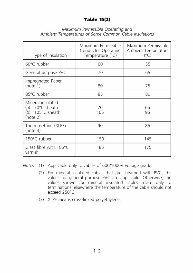
8/23/2019 Electricity Wiring
http://slidepdf.com/reader/full/electricity-wiring 112/337
Table 15(2)
Maximum Permissible Operating and Ambient Temperatures of Some Common Cable Insulations
Type of Insulation
Maximum PermissibleConductor Operating
Temperature (°C)
Maximum PermissibleAmbient Temperature
(°C)
60°C rubber 60 55
General purpose PVC 70 65
Impregnated Paper(note 1) 80 75
85°C rubber 85 80
Mineral-insulated(a) 70°C sheath(b) 105°C sheath(note 2)
70105
6595
Thermosetting (XLPE)(note 3)
90 85
150°C rubber 150 145
Glass fibre with 185°Cvarnish
185 175
Notes: (1) Applicable only to cables of 600/1000V voltage grade.
(2) For mineral insulated cables that are sheathed with PVC, the
values for general purpose PVC are applicable. Otherwise, thevalues shown for mineral insulated cables relate only toterminations; elsewhere the temperature of the cable should notexceed 250°C.
(3) XLPE means cross-linked polyethylene.
112

8/23/2019 Electricity Wiring
http://slidepdf.com/reader/full/electricity-wiring 113/337
00
0
0
0
0
0
0
00
0
0
Table 15(3)
Concise List of External Influences
AA Temperature (°C)
AA1 - 60°C + 5°CAA2 - 40°C + 5°CAA3 - 25°C + 5°CAA4 - 5°C + 40°CAA5 + 5°C + 40°CAA6 + 5°C + 60°CAA7 - 25°C + 55°CAA8 - 50°C + 40°C
AB Temperature andhumidity
AB1 - 60°C + 5°C 3% 100%AB2 - 40°C + 5°C 10% 100%
AB3 - 25°C + 5°C 10% 100%AB4 - 5°C + 40°C 5% 95%AB5 + 5°C + 40°C 5% 85%AB6 + 5°C + 60°C 10% 100%AB7 - 25°C + 55°C 10% 100%AB8 - 50°C + 40°C 15% 100%
AC Altitude (metres)
AC1 р2,000 metresAC2 >2,000 metres
AD Water
AD1 NegligibleAD2 DropsAD3 SprayAD4 SplashesAD5 JetsAD6 WavesAD7 ImmersionAD8 Submersion
AE Foreign bodies
AE1 NegligibleAE2 SmallAE3 Very small
AE4 Light dustAE5 Moderate dustAE6 Heavy dust
AF Corrosion
AF1 NegligibleAF2 AtmosphericAF3 IntermittentAF4 Continuous
AG Impact
AG1 Low severityAG2 Medium severityAG3 High severity
AH Vibration
AH1 Low severityAH2 Medium severityAH3 High severity
AK Flora
AK1 No hazardAK2 Hazard
AL Fauna
AL1 No hazardAL2 Hazard
AM Electromagnetic,electrostatic, orionizing influences
AM1 Harmonics, interharmonicsAM2 Signalling voltagesAM3 Voltage amplitude
variations
AM4 Voltage unbalanceAM5 Power frequency variationsAM6 Induced low-frequency
voltagesAM7 Direct current in a.c.
voltagesAM8 Radiated magnetic fieldAM9 Electric fieldsAM21 Induced oscillatory voltages
or currentsAM22 Conducted unidirectional
transients of thenanosecond time scale
AM23 Conducted unidirectional
transients of themicrosecond to themillisecond time scale
AM24 Conducted oscillatorytransients
AM25 Radiated high frequencyphenomena
AM31 Electrostatic dischargesAM41 lonization
AN Solar radiation
AN1 LowAN2 MediumAN3 High
AP Seismic effects
AP1 NegligibleAP2 Low severityAP3 Medium severityAP4 High severity
AQ Lightning
AQ1 Negligible
AQ2 Indirect exposureAQ3 Direct exposure
AR Movement of air
AR1 LowAR2 MediumAR3 High
AS Wind
AS1 LowAS2 MediumAS3 High
(Note: The information above is extracted from IEC 60364-5-51 ed.5.0 “Copyright©2005 IEC
Geneva, Switzerland.www.iec.ch”.)
113
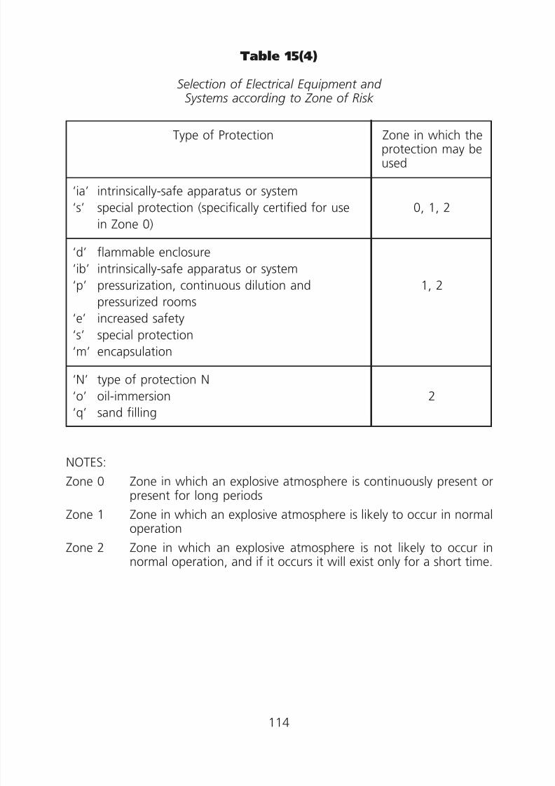
8/23/2019 Electricity Wiring
http://slidepdf.com/reader/full/electricity-wiring 114/337
Table 15(4)
Selection of Electrical Equipment andSystems according to Zone of Risk
Type of Protection Zone in which theprotection may beused
‘ia’ intrinsically-safe apparatus or system
‘s’ special protection (specifically certified for use
in Zone 0)
0, 1, 2
‘d’ flammable enclosure‘ib’ intrinsically-safe apparatus or system
‘p’ pressurization, continuous dilution and
pressurized rooms
‘e’ increased safety
‘s’ special protection
‘m’ encapsulation
1, 2
‘N’ type of protection N‘o’ oil-immersion
‘q’ sand filling
2
NOTES:
Zone 0 Zone in which an explosive atmosphere is continuously present orpresent for long periods
Zone 1 Zone in which an explosive atmosphere is likely to occur in normaloperation
Zone 2 Zone in which an explosive atmosphere is not likely to occur innormal operation, and if it occurs it will exist only for a short time.
114

8/23/2019 Electricity Wiring
http://slidepdf.com/reader/full/electricity-wiring 115/337
Table 15(5)
Relationship between T Class and Maximum Surface Temperature
T Class Maximum Surface Temperature (°C)
T1
T2
T3
T4
T5
T6
450
300
200
135
100
85
115

8/23/2019 Electricity Wiring
http://slidepdf.com/reader/full/electricity-wiring 116/337
Code 16 OVERHEAD LINE INSTALLATIONS
16A General
16B Installation of Overhead Lines
16C Joints of Overhead Lines
16D Service to Building
16E Conductor to Ground Clearance
(1) Termination onto a building
(2) Any point of the span
16F Pole
(1) Material
(2) Installation
16G Stay Wire
(1) Material
(2) Installation
16H Carrier Wire
(1) Material
(2) Installation
16I Earthing of Metallic Parts and Earth Leakage Protection
116
8/23/2019 Electricity Wiring
http://slidepdf.com/reader/full/electricity-wiring 117/337
Code 16 OVERHEAD LINE INSTALLATIONS
16A General
Hard-drawn copper or solid aluminium PVC insulated PVC sheathed armoured
or non-armoured single or multi-core or bunched cables, suspended on carrierwires, are acceptable for low voltage overhead line installations.
16B Installation of Overhead Lines
Cables for overhead lines should be securely supported on insulators.Alternatively, the cables should be attached to the carrier wire by self-retaining nylon fasteners of suitable size and strength and evenly spaced atsuitable intervals to prevent undue stress on the cables.
16C Joints of Overhead Lines
(a) Mid-span joints in overhead lines are not acceptable.
(b) Straight joints, if any, should be made at the pole and should be properlydesigned, installed and insulated from the pole.
16D Service to Building
(a) Where overhead lines enter into a building, the cables should be takeninto the building through an arrangement with sufficient size andadequate protection from mechanical damage.
(b) A separate earthing system at each building comprising earth electrodes,earthing conductors, earthing terminal etc. should be provided for eachbuilding fed from an overhead line supply.
16E Conductor to Ground Clearance
(1) Termination onto a building
In cases where an overhead line is to be terminated onto a building andit is not possible to achieve the required height by attaching the overheadline to the roof of the building, an extension pole should be fitted to thebuilding, and the overhead line should be attached to the pole.
Alternatively a pole should be erected adjacent to the building, and thesupply cable from the pole to the building should be adequatelyprotected from mechanical damage. For this purpose, undergroundarmoured cables are acceptable.
117

8/23/2019 Electricity Wiring
http://slidepdf.com/reader/full/electricity-wiring 118/337
(2) Any point of the span
The conductor to ground clearance of any point of the span of theoverhead line should be not less than:
(a) 5.8 m across any space accessible to vehicular traffic such as roads,
car parks etc., or(b) 5.2 m in other positions; or
(c ) the tallest height restriction where height restriction is imposed onany location.
16F Pole
(1) Material
Poles should be made of steel, concrete, wood or other durable materialof adequate strength.
(2) Installation
Poles should be erected in such a manner to withstand the forces actingon them due to overhead lines, carrier wires and wind etc.
16G Stay Wire
(1) Material
Stay wires should be of stranded galvanised steel not less than sevenstrands each having a nominal diameter of 2 mm (i.e. 7/2 mm).
(2) Installation
(a) Stay wires may be used at the terminal poles or at poles where theoverhead line changes direction. The stays wires, where used, shouldbe placed in such a manner so as to take the pull exerted by the lines
effectively.(b) Stay wires should be properly and securely terminated at each end
so as to withstand the forces acting on the wires.
16H Carrier Wire
(1) Material
Carrier wires should be made of a stranded galvanised steel having a
nominal overall diameter not less than 4 mm.
(2) Installation
Carrier wires should be firmly fixed to supports.
118

8/23/2019 Electricity Wiring
http://slidepdf.com/reader/full/electricity-wiring 119/337
16I Earthing of Metallic Parts and Earth LeakageProtection
(a) The metallic poles, the steel carrier wires and the stay wires, should bepermanently and effectively earthed at the main earthing terminals atboth ends of the circuit. To meet this requirement the steel carrier wiremay be used as a protective conductor to earth the metallic poles andstay wires provided that the electrical continuity of the carrier wire isdurably maintained throughout the entire run of the circuit.
(b) Where an electrical installation is supplied from overhead line system, theinstallation should be protected against earth leakage by residual currentdevice (see Code 11B).
119
8/23/2019 Electricity Wiring
http://slidepdf.com/reader/full/electricity-wiring 120/337
Code 17 DISPLAY OF LABELS AND NOTICES
17A Warning Notice for Substations and Switchrooms
(1) Warning notice for substations
(2) Warning notice for switchrooms
(3) Warning notice for distribution boards
17B Warning Notice for Connection of Earthing and Bonding Conductors
17C Warning Notice for Repair
17D Notice of Periodic Testing of Electrical Installations
17E Notice of Testing for Residual Current Devices
17F Warning Notice for Installation Having Both New and Old Cable Colours
120
8/23/2019 Electricity Wiring
http://slidepdf.com/reader/full/electricity-wiring 121/337
Code 17 DISPLAY OF LABELS AND NOTICES
17A Warning Notice for Substations and Switchrooms
(1) Warning notice for substations‘DANGER—SUBSTATION, UNAUTHORISED ENTRY PROHIBITED’ and‘危險 ——電力分站,未經授權不得內進 ’ in legible letters andcharacters. “DANGER” and ‘危險 ’ should not be less than 30 mm highand each other letters and characters not less than 15 mm high, eitherpainted on the outside of the door of the substation, or engraved onplastic boards permanently fixed on the outside of the door of thesubstation.
(2) Warning notice for switchrooms
‘DANGER—ELECTRICITY, UNAUTHORISED ENTRY PROHIBITED’ and‘危險——有電,未經授權不得內進 ’ in legible letters and characters.‘DANGER’ and ‘危險 ’ should not be less than 30 mm high and eachother letter and characters not less than 15 mm high, either painted onthe outside of the door of the switchroom or engraved on plastic boardspermanently fixed on the outside of the door of the switchroom.
(3) Warning notice for distribution boards‘DANGER’ and ‘危險 ’ in red legible letters and characters each not lessthan 10 mm high, displayed at or near each distribution board isacceptable.
17B Warning Notice for Connection of Earthing andBonding Conductors
‘SAFETY ELECTRICAL CONNECTION—DO NOT REMOVE’ and ‘安全接地終端——切勿移去 ’ in legible letters and characters each not less than 5 mmhigh to be permanently fixed at or near the point of connection of everyearthing conductor to an earth electrode, and at or near each main bondingconnection.
17C Warning Notice for Repair
‘CAUTION—EQUIPMENT UNDER REPAIR’ and ‘小心 ——器具待修
’ and/or‘CAUTION—MEN AT WORK (小心——工程進行中) ’ in legible letters andcharacters each not less than 50 mm high, displayed at or near the electricalequipment and at the isolating device associated with the equipment isacceptable. Examples for display of such notices are:
121

8/23/2019 Electricity Wiring
http://slidepdf.com/reader/full/electricity-wiring 122/337
(a) on a distribution board or switch or circuit breaker controlling the circuiton which work is being carried out; and
(b) at or near any equipment where bare or live parts which are normallyprotected from direct contact are uncovered and exposed for work to becarried out.
17D Notice of Periodic Testing of Electrical Installations
‘This installation must be tested and certified by a grade A/B/C/H/R* electricalworker before (date) **’ and ‘本裝置須於 年 月 日 **前由
————— ————— —————
A/B/C/H/R* 級電業工程人員測試及發出證明書 ’ in legible letters andcharacters each not less than 5 mm, permanently fixed at or near the maindistribution board or main switch of a periodically tested electrical installationreferred to in regulation 20 (see Code 20) is acceptable.
(Note: * delete whichever inapplicable.
** the date entered on this notice is the date of the next certificateto be issued and is to be up-dated by the registered electricalworker who is certifying the installation.)
17E Notice of Testing for Residual Current Devices
‘Press to test at least quarterly’ and ‘最少每三個月按鈕測試 ’ in legible letters
and characters each not less than 5 mm, permanently fixed at or near aresidual current device is acceptable.
17F Warning Notice for Installation Having Both New andOld Cable Colours
‘小心!此電力裝置包含新舊顏色電線。在進行加裝、改裝或修理工作前,務須正確識別所有導體。’ and ‘CAUTION! THIS INSTALLATION HAS BOTH NEWAND OLD CABLE COLOURS. GREAT CARE SHOULD BE TAKEN BEFORE
UNDERTAKING EXTENSION, ALTERATION OR REPAIR THAT ALLCONDUCTORS ARE CORRECTLY IDENTIFIED.’ in black legible letters andcharacters, and in yellow background. ‘小心’ and ‘CAUTION’ should not beless than 10 mm in height and other letters and characters not less than 5 mmin height. The warning notice should have a minimum size of 100mm (width)× 75mm (height). It should be displayed at or close to the nearest upstreamdistribution board (e.g. main switchboard, sub-main distribution board orconsumer unit) of an installation where cables in new colour code are installedin an existing installation with old colour coded cables.
122

8/23/2019 Electricity Wiring
http://slidepdf.com/reader/full/electricity-wiring 123/337
Code 18 ALTERATIONS AND ADDITIONS
18A Requirements for Alterations or Additions to a Fixed Installation
18B Approval from the Electricity Supplier
123
8/23/2019 Electricity Wiring
http://slidepdf.com/reader/full/electricity-wiring 124/337
Code 18 ALTERATIONS AND ADDITIONS
18A Requirements for Alterations or Additions to a FixedInstallation
(a) For any alteration or addition to an existing fixed installation, theregistered electrical worker responsible for the work should:
(i) carry out the alteration or addition in compliance with the WiringRegulations,
(ii) verify that the alteration or addition does not impair in any way thesafety of the existing installation, and
(iii) verify that new colour cables are installed in compliance with therequirements in Appendix 18.
(b) For the purposes of subparagraph (a) above, the following essential itemsshould be checked and ascertained by the responsible registered electricalworker:
(i) the total current demand for the installation after the alteration oraddition should not exceed the approved loading;
(ii) the ratings and the conditions of the existing electrical equipment ofthe affected parts are suitable and adequate for the altered circum-stances; and
(iii) the protection against overcurrent, earth fault currents anddangerous earth leakage currents for the affected parts is altered asnecessary for the altered circumstances.
(c ) In the case of an alteration or addition to an installation which isconnected to rising mains, the owner of the installation should, beforecommencing any alteration or addition, obtain agreement from theowner of the rising mains by completing form “Confirmation ofAgreement from Owner of Rising Mains for Connection of ElectricalInstallation with an Increased Current Demand” provided by Electricity
Supplier if the new current demand of the installation after the alterationor the addition will exceed the existing approved loading before thealteration or addition is carried out on the installation.
18B Approval from the Electricity Supplier
Any person who wishes to have his electricity supply increased over and abovethe approved loading, or extended beyond the premises to which the supplyis originally intended, should obtain prior approval from the electricity supplierconcerned before any alteration or addition is carried out.
124

8/23/2019 Electricity Wiring
http://slidepdf.com/reader/full/electricity-wiring 125/337
Code 19 FIRST INSPECTION, TESTING ANDCERTIFICATION
19A Certification on Completion of an Installation
19B Work Completion Certificate
125
8/23/2019 Electricity Wiring
http://slidepdf.com/reader/full/electricity-wiring 126/337
Code 19 FIRST INSPECTION, TESTING ANDCERTIFICATION
19A Certification on Completion of an Installation
(a) Certification on the design—
After the design is completed for new work, alteration or addition to bemade to an existing installation, it should be certified, before installation,by a registered electrical worker that the relevant design is in compliancewith the Wiring Regulations.
(b) Certification on the installation—
After an installation is completed, or work completed subsequent torepair, alteration or addition made to an existing installation and beforeit is energized for use, it should be inspected, tested and certified by aregistered electrical worker that the wiring installation is completed tothe relevant design and is in compliance with the Wiring Regulations.
(c ) If the installation, alteration or addition is designed, inspected and testedby the same electrical worker, he should certify both the design and theinstallation as required under subparagraphs (a) and (b).
(d ) In the case of a repair, alteration or addition to an installation, only theaffected parts of the installation need to be inspected, tested andcertified.
(e) Certification as required in subparagraphs (a) and (b) should be madeon prescribed forms specified by the Director (i.e. Work CompletionCertificate).
19B Work Completion Certificate
(a) For the purpose of regulations 19(1) and 19(2), the registered electrical
worker(s) and contractor(s) should sign work completion certificate( s
) andissue it to the owner after completion of the electrical installation or anywork subsequent to repair, alteration or addition to an existinginstallation. This should be done before the installation is energised.
(b) It is recommended that in order to expedite the application for supplyconnection, a copy of the certificate may be copied to the electricitysupplier concerned.
(c ) Where an installation is subdivided into more than one part and
individual parts are not inspected and tested by the same registeredelectrical worker, a single certificate may be issued and certified by aregistered electrical worker to cover a number or all of the individualparts, provided that he has received the appropriate certificates signed byother registered electrical workers for the individual parts.
126

8/23/2019 Electricity Wiring
http://slidepdf.com/reader/full/electricity-wiring 127/337
(d ) Every certificate should be signed by the registered electrical workerand/or the registered electrical contractor as required in the certificate.Where a registered electrical contractor is not employed as permittedunder section 35(3) of the Electricity Ordinance, the owner of theelectrical installation who employs the registered electrical worker to do
the work should sign as the registered electrical contractor and shouldthen assume responsibilities of a registered electrical contractor.
(e) Proforma of the Work Completion Certificate can be obtainedfrom EMSD’s Customer Services Office or downloaded fromwww.info.gov.hk/forms.
127

8/23/2019 Electricity Wiring
http://slidepdf.com/reader/full/electricity-wiring 128/337
Code 20 PERIODIC INSPECTION, TESTING ANDCERTIFICATION
20A Fixed Electrical Installations Specified in Regulation 20(1)
(1) Places of public entertainment(2) Premises for the manufacturing or storing of dangerous goods
(3) High voltage fixed installations
20B Fixed Electrical Installations Specified in Regulations 20(2), 20(3) and20(4)
20C Periodic Test Certificate
128

8/23/2019 Electricity Wiring
http://slidepdf.com/reader/full/electricity-wiring 129/337
Code 20 PERIODIC INSPECTION, TESTING ANDCERTIFICATION
20A Fixed Electrical Installations Specified in Regulation
20(1)Fixed electrical installations having any approved loading at the followingtypes of premises are required to be inspected, tested and certified at leastonce every year:
(1) Places of public entertainment
Places of public entertainment as defined in the Places of PublicEntertainment Ordinance (Cap. 172) including any place, building,erection or structure, whether temporary or permanent, capable ofaccommodating the public in or on which a public entertainment ispresent or carried on whether on one occasion or more; including anyconcert, stage play, stage performance or other musical, dramatic ortheatrical entertainment or any part thereof, any cinematography display,lecture, story-telling, circus, exhibition of pictures, photographs or books,exhibition of dancing, conjuring or juggling, acrobatic performanceexhibition of abnormal persons or animals, any sporting exhibition orcontest, any bazaar, any merry-go-round, flying wheel or othermechanical device designed for amusement.
(2) Premises for the manufacturing or storing of dangerous goods
(a) Premises for the manufacturing or storing of dangerous goodsclassified under categories of the Dangerous Goods (Application andExemption) Regulations (Cap. 295), previously known as theDangerous Goods (Classification) Regulations, are as follows:
Category 1 — explosives and blasting agents
Category 2 — compressed gases
Category 3 — corrosive substances
Category 4 — poisonous substances
Category 5 — substances giving off inflammable vapour
Category 6 — substances which become dangerous by interactionwith water
Category 7 — strong supporters of combustion
Category 8 — readily combustible substances
Category 9 — substances liable to spontaneous combustionCategory 9A — combustible goods exempted from sections 6 to 11
of the Dangerous Goods Ordinance
Category 10 — other dangerous substances
129

8/23/2019 Electricity Wiring
http://slidepdf.com/reader/full/electricity-wiring 130/337
(b) Examples of the above are dangerous goods stores, dangerousgoods storage tanks, gas stations, petroleum and diesel fillingstations and liquefied petroleum gas stations etc.
(3) High voltage fixed installations
(a) Premises having high voltage fixed installations that are fed directlyfrom a high voltage supply are required to be inspected, tested andcertified at least once every year. Examples of such installations are:
(i) high voltage switchrooms and substations under the control ofthe owners (e.g. of a large commercial complex);
(ii) high voltage fixed installations such as large plant andmachinery.
(b) High voltage electrostatic equipment and high voltage discharge
lighting such as neon signs which are fed from low voltage suppliesare not considered as high voltage fixed installations. They areconsidered as part of a low voltage installation.
20B Fixed Electrical Installations Specified in Regulations20(2), 20(3) and 20(4)
(1) Fixed electrical installations in factories and industrial undertakings havingan approved loading exceeding 200 amperes, single or three phase at
nominal low voltage are required to be inspected, tested and certified atleast once every five years.
(2) Fixed electrical installations in premises other than those mentioned inCodes 20A or 20B(1) above having an approved loading exceeding 100amperes single or three phase at nominal low voltage are required to beinspected, tested and certified at least once every five years. Examples ofsuch installations are rising mains, protective conductors, earthingfacilities, and power supply to lifts, water pumps, public lighting andother communal services in the common area of domestic premises andfixed installations in offices etc.
(3) Low voltage fixed electrical installation located in one of the followingtype of premises should be inspected, tested and certified at least onceevery five years:
(a) hotel or guest house;
(b) hospital or maternity home;
(c ) school;
(d ) premises of the institutions listed in section 2 of the EducationOrdinance (Cap. 279) including technical institutions and universities;
(e) child care centre; and
130
8/23/2019 Electricity Wiring
http://slidepdf.com/reader/full/electricity-wiring 131/337
(f ) premises that the Director may, by notice posted to or served on theowner, specify that he considers could cause great harm in the eventof an electrical accident.
20C Periodic Test Certificate
(1) The owner of an installation which requires periodic testing should delivera test certificate to the Director for endorsement within 2 weeks after thedate of the certificate. The owner should submit a current endorsementfee for each certificate delivered to the Director.
(2) Where an installation is subdivided into more than one part andindividual parts are not inspected and tested by the same registeredelectrical worker, a single test certificate may be issued and certified by aregistered electrical worker to cover a number or all of the individual
parts, provided that he has received the appropriate test certificatessigned by other registered electrical workers for the individual parts.
(3) The test certificates should be in prescribed forms specified by theDirector and proforma of the certificates can be obtained from EMSD’sCustomer Services Office or downloaded from www.info.gov.hk/forms.
(4) All installations which require periodic testing and are connected toelectricity supplies on or before the commencement date of the WiringRegulations (1 June 1992) are considered to have been inspected, tested
and certified on that date.
131

8/23/2019 Electricity Wiring
http://slidepdf.com/reader/full/electricity-wiring 132/337
Code 21 PROCEDURES FOR INSPECTION,TESTING AND CERTIFICATION
21A Inspection of Low Voltage Installations
21B Testing of Low Voltage Installations
(1) Safety
(2) Sequence of tests
(3) Continuity of ring final circuit
(4) Continuity of protective conductors
(5) Earth electrode resistance
(6) Insulation resistance(7) Polarity
(8) Earth fault loop impedance
(9) Functions of all devices including protective devices
(10) Additional checks for installations in hazardous environment
21C Inspection of High Voltage (H.V.) Installations
21D Testing of High Voltage Installations
(1) Safety
(2) Testing requirements
21E Points to be Noted by Registered Electrical Workers
(1) Signing of certificates
(2) Dates of tests, inspections and certification(3) Items to be inspected and tested
(4) Related ordinance and regulations to be observed
(5) Energisation of installation for testing purposes
(6) Standard symbols to be used
132

8/23/2019 Electricity Wiring
http://slidepdf.com/reader/full/electricity-wiring 133/337
Code 21 PROCEDURES FOR INSPECTION,TESTING AND CERTIFICATION
21A Inspection of Low Voltage Installations
A visual inspection should be made to verify that the electrical equipment asinstalled is correctly selected and erected in accordance with the WiringRegulations and this CoP, and that there is no apparent damage. The visualinspection should include a check on the following items, where appropriate:
(a) adequacy of working space, access, and maintenance facilities,
(b) connections of conductors,
(c ) identification of conductors,
(d ) adequacy of the sizes of conductor in relation to current carrying capacityand voltage drop,
(e) correct connections of all equipment with special attention to socketoutlets, lampholders, isolators, switches, residual current devices,miniature circuit breakers, and protective conductors,
(f ) presence of fire barriers and protection against thermal effects,
( g) methods of protection against direct contact with live parts (includingmeasurement of distances where appropriate), i.e. protection byinsulation of live parts, or protection by barriers or enclosures,
(h) presence of appropriate devices for isolation and switching,
(i) choice and setting of protective and indicative devices,
( j ) labelling of circuits, fuses, protective devices, switches, isolators andterminals,
(k ) selection of equipment and protective measures appropriate to adverseenvironmental conditions,
(l ) presence of danger and warning notices,
(m) presence of diagrams, instructions and other similar information,
(n) connection of single pole devices for protection or switching in phaseconductors only,
(o) methods of fault protection,
( p) prevention of mutual detrimental influence,
(q) presence of undervoltage protective devices,
(r ) erection method.
133

8/23/2019 Electricity Wiring
http://slidepdf.com/reader/full/electricity-wiring 134/337
21B Testing of Low Voltage Installations
(1) Safety
Precautionary measures should be taken during testing and the methodof tests should be such that no danger to persons or property can occur
even if the circuit being tested is defective.
(2) Sequence of tests
(a) The following items, where relevant, are to be tested preferably inthe sequence indicated below:
(i) continuity of protective conductors, including main andsupplementary equipotential bonding,
(ii) continuity of ring final circuit conductors,
(iii) insulation resistance,
(iv) polarity,
(v) earth electrode resistance,
(vi) earth fault loop impedance,
(vii) functions of all protective devices,
(viii) functions of all items of equipment.
(b) In the event of any test indicating failure to comply, that test andthose preceding, the results of which may have been influenced by
the fault indicated, should be repeated after the fault has beenrectified.
(3) Continuity of protective conductors
Every protective conductor, including all conductors and any extraneousconductive parts used for equipotential bonding should be tested forcontinuity. The test should be made by connecting together the neutraland protective conductors at the mains position and checking betweenearth and neutral at every outlet by a continuity tester, which should
show a reading near zero.(4) Continuity of ring final circuit
(a) The ring circuit should be tested from the distribution board. Theends of the two cables forming the phase conductor should beseparated, and a continuity test should show a reading near zerobetween the two; the same tests to be made between the twocables that form the neutral conductor, and between the two cablesthat form the protective conductor (see Figure 21(1)).
(b) The testing method in subparagraph (a) above is only applicablewhen the ring circuit has been inspected throughout, prior to thetest, to ascertain that no interconnection (multi-loops) exists on thering circuit. Otherwise, the testing methods stipulated in Part 3 ofthe Guidance Note 3 to BS7671, should be adopted instead.
134
8/23/2019 Electricity Wiring
http://slidepdf.com/reader/full/electricity-wiring 135/337
(5) Insulation resistance
(a) A suitable d.c. insulation tester should be used to measure insulationresistance. Care should be taken to ensure that the insulation of theequipment under test can withstand the test voltage withoutdamage.
(b) The main switchboard and each distribution circuit should be testedseparately. To carry out this test, it is acceptable to divide largeinstallation into sections with groups of outlets. The term ‘outlet’ inthis case includes every point and every switch. A socket outlet orappliance or luminaire incorporating a switch is regarded as oneoutlet.
(c ) When measured with all fuse links in place, all switches and circuitbreakers (including, if practicable, the main switch) closed and allpoles or phases of the wiring electrically connected together, theinsulation resistance to earth should not be less than the appropriatevalues given in Table 21(1), as illustrated in Figure 21(4).
(d ) When measured between all conductors connected to any onephase or pole of the supply and, in turn, all conductors connected toeach other phase or pole, as shown in Figure 21(5), the insulationresistance should not be less than the appropriate values in Table21(1).
(e) In carrying out the test:(i) wherever practicable, all lamps should be removed and all
current using equipment should be disconnected and all localswitches controlling lamps or other equipment should beclosed;
(ii) where the removal of lamps and/or the disconnection of currentusing equipment is impracticable, the local switches controllingsuch lamps and/or equipment should be open;
(iii) electronic devices connected in the installation should beisolated or short circuited where appropriate so that they arenot damaged by the test voltage.
(iv) where the circuits contain voltage sensitive devices, the testshould measure the insulation resistance to earth with all liveconductors (including the neutral) connected together.
(f ) Where equipment is disconnected for the test and the equipmenthas exposed conductive parts required to be connected to protectiveconductors, the insulation resistance between the exposed
conductive parts and all live parts of the equipment should bemeasured separately and should have a minimum insulationresistance not less than 1 megohm.
135

8/23/2019 Electricity Wiring
http://slidepdf.com/reader/full/electricity-wiring 136/337
(6) Polarity
(a) A test of polarity, as illustrated in Figure 21(6), should be carried outto verify that:
(i) every fuse and single-pole control and protective device is
connected in the phase conductor only;(ii) centre-contact bayonet and Edison-type screw lampholders toIEC 60238 in circuits having an earthed neutral conductor, havetheir outer or screwed contacts connected to that neutralconductor; and
(iii) wiring has been correctly connected to socket outlets andsimilar accessories.
(7) Earth electrode resistance
(a) A proper earth electrode resistance tester should be used to measureearth electrode resistance. An alternating current at 50 Hz of asteady value is passed between the earth electrode T and an auxiliaryearth electrode T
1placed at a separation distance recommended by
the manufacturer of the tester but in any case should not be lessthan 20 metres away. A second auxiliary earth electrode T
2, which
may be a metal spike driven into the ground, is then inserted halfway between T and T
1, and the voltage drop between T and T
2,
divided by the current flowing between T and T1, gives a measuredearth electrode resistance of earth electrode T.
(b) The test method is depicted in Figure 21(2).
(c ) For an electrical installation having four or more earth electrodeswhich are installed more or less in line, following a general directionnot exceeding 15° deviation and with separation between adjacentelectrodes not less than the recommended distance by themanufacturer of the tester but in any case not less than 20 metres,
these electrodes can be used in turn as the auxiliary electrodes forthe purpose of measuring the earth electrode resistances, asillustrated in Figure 21(3).
(d ) The following alternative method for measuring the earth electroderesistance may be used if the electricity supply is connected. A loopimpedance tester should be connected between the phaseconductor at the origin of the installation and the earth electrodewith the test link open, and a test performed. This impedancereading could be treated as the electrode resistance.
136
8/23/2019 Electricity Wiring
http://slidepdf.com/reader/full/electricity-wiring 137/337
(8) Earth fault loop impedance
(a) The earth fault loop impedance should be measured by a phase-earth loop tester with a scale calibrated in ohms.
(b) The earth fault loop impedance should not exceed the requirements
of Code 11.(c ) Before the test begins, it is essential to establish, by inspection, that
the earthing conductor and all relevant earth connections are in place,and that the bonding connection to electricity supplier’s earthingfacilities is disconnected. Measures should be taken, during theimpedance tests especially when the earth leakage protective devicesare effectively removed for the duration of the tests, to ensure that theinstallation is not being used other than by person( s) carrying out thetests.
(9) Functions of all devices including protective devices
(a) Functional Test of RCD
(i) Function of residual current devices should be checked by aresidual current device tester simulating an earth fault in orderto verify its effective operation. The in-built test button shouldalso be tested for proper functioning. One of the testingmethods is specified in subparagraph (ii) and (iii) below. Other
testing methods complying with relevant national/internationalstandards are also acceptable.
(ii) The test should be made on the load side of the RCD betweenthe phase conductor of the protected circuit and the associatedcpc. The load should be disconnected during the test.
(iii) For general purpose RCDs to IEC 61008 or RCBOs to IEC61009, with a leakage current flowing equivalent to 50% of therated tripping current of the RCD, the device should not open.When a leakage current is flowing equivalent to 100% of the
rated tripping current of the RCD, the device should open in lessthan 300 ms unless it is of “Type S” (or selective) whichincorporates an intentional time delay, when it should tripwithin the time range from 130 ms to 500 ms.
(b) Function of other protective devices, such as miniature circuitbreakers, moulded case circuit breakers, air circuit breakers, fusedswitches, switch-fuses and protective relays etc. should be checkedby hand operation as appropriate.
(c ) Function of all items of equipment such as isolators, switches andindicative devices should be checked by hand operation.
137
8/23/2019 Electricity Wiring
http://slidepdf.com/reader/full/electricity-wiring 138/337
(d ) Secondary Injection Test
(i) The overload and fault current protection characteristics ofprotection relays should be verified with secondary injectiontest.
(ii) The test should be carried out by injecting a.c. of different
magnitudes into the relay terminals and measuring the relayoperating time. The operating time should be checked againstthe manufacturer’s data sheet.
(10) Additional checks for installations in hazardous environment
The following additional checks, where appropriate, should be carriedout for installations in hazardous environment:
(a) Where appropriate, the area involved should be checked to ensure
‘gas free’ condition before insulation and earth fault loop impedancetest are carried out.
(b) All equipment should be suitably protected according to the types ofprotection under Code 15. The integrity of the type of protectionprovided for the equipment should not be jeopardised by themethod of installation. No alteration that may invalidate theconditions of protection can be used.
(c ) Equipment should be kept clean and free from accumulation of dust,
foreign particles and deleterious substances. Equipment is kept freefrom condensation.
(d ) All lamps, fuses and replaceable parts should be checked so thatcorrect rating and types are being used.
(e) The surface temperature of all equipment should be appropriate tothe type of protection being provided.
21C Inspection of High Voltage (H.V.) Installations
Inspection of H.V. installations should follow those for L.V. installations listedin Code 21A with additional checks on the following items where relevant:
(a) provision of suitable locking facilities for every entry to an H.V.switchroom/substation;
(b) continuity of protective conductors especially the bonding of all exposedconductive parts; and
(c ) provision of padlock facilities for shutters, key boxes etc.
138
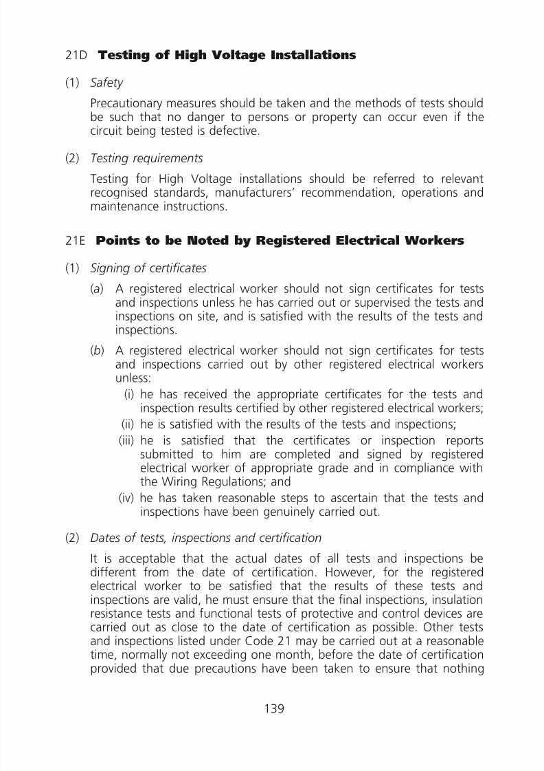
8/23/2019 Electricity Wiring
http://slidepdf.com/reader/full/electricity-wiring 139/337
21D Testing of High Voltage Installations
(1) Safety
Precautionary measures should be taken and the methods of tests shouldbe such that no danger to persons or property can occur even if thecircuit being tested is defective.
(2) Testing requirements
Testing for High Voltage installations should be referred to relevantrecognised standards, manufacturers’ recommendation, operations andmaintenance instructions.
21E Points to be Noted by Registered Electrical Workers
(1) Signing of certificates
(a) A registered electrical worker should not sign certificates for testsand inspections unless he has carried out or supervised the tests andinspections on site, and is satisfied with the results of the tests andinspections.
(b) A registered electrical worker should not sign certificates for testsand inspections carried out by other registered electrical workers
unless:(i) he has received the appropriate certificates for the tests and
inspection results certified by other registered electrical workers;
(ii) he is satisfied with the results of the tests and inspections;
(iii) he is satisfied that the certificates or inspection reportssubmitted to him are completed and signed by registeredelectrical worker of appropriate grade and in compliance withthe Wiring Regulations; and
(iv) he has taken reasonable steps to ascertain that the tests andinspections have been genuinely carried out.
(2) Dates of tests, inspections and certification
It is acceptable that the actual dates of all tests and inspections bedifferent from the date of certification. However, for the registeredelectrical worker to be satisfied that the results of these tests andinspections are valid, he must ensure that the final inspections, insulationresistance tests and functional tests of protective and control devices are
carried out as close to the date of certification as possible. Other testsand inspections listed under Code 21 may be carried out at a reasonabletime, normally not exceeding one month, before the date of certificationprovided that due precautions have been taken to ensure that nothing
139

8/23/2019 Electricity Wiring
http://slidepdf.com/reader/full/electricity-wiring 140/337
will have affected the results of these tests and inspections during thisperiod.
(3) Items to be inspected and tested
List of items to be inspected and tested for initial tests and periodic testsare shown in Code 22D.
(4) Related ordinance and regulations to be observed
Other statutory requirements in relation to electrical installations shouldalso be referred to during the inspection, including in particular:
(a) (i) Fire Services Ordinance,
(ii) Fire Services (Installations and Equipment) Regulations,
(b) (i) Fire Safety (Commercial Premises) Ordinance,(ii) Fire Safety (Buildings) Ordinance,
(c ) (i) Factories and Industrial Undertakings Ordinance,
(ii) Factories and Industrial Undertakings (Electricity) Regulations,
(iii) Construction Sites (Safety) Regulations,
(iv) Factories and Industrial Undertaking (Work in Compressed Air)Regulations,
(v) Factories and Industrial Undertakings (Spraying of Inflammable
Liquid) Regulations,(vi) Factories and Industrial Undertakings (Cargo and Container
Handling) Regulations,
(d ) (i) Dangerous Goods Ordinance,
(ii) Dangerous Goods (General) Regulations.
(5) Energisation of installation for testing purposes
To energise an installation or part of it for testing by a registeredelectrical worker prior to the issue of the relevant certificate is acceptable.
(6) Standard symbols to be used
Standard symbols to Appendix 8 should be used in schematic diagramswhere appropriate.
140

8/23/2019 Electricity Wiring
http://slidepdf.com/reader/full/electricity-wiring 141/337
Table 21(1)
Minimum Values of Insulation Resistance
Circuit Nominal Voltage(Volts)
Test Voltage d.c.(Volts)
Minimum
InsulationResistance(megohms)
Extra-low voltage circuits when thecircuit is supplied from a safetyisolating transformer/SELV
250 0.5
Up to and including 500V with theexception of the above cases
500 1.0
Above 500V 1 000 1.0
141

8/23/2019 Electricity Wiring
http://slidepdf.com/reader/full/electricity-wiring 142/337
142

8/23/2019 Electricity Wiring
http://slidepdf.com/reader/full/electricity-wiring 143/337
143
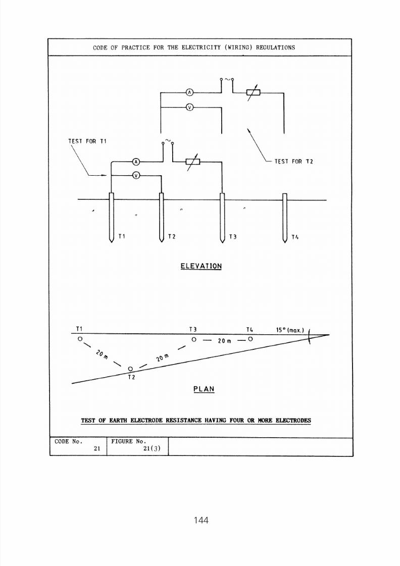
8/23/2019 Electricity Wiring
http://slidepdf.com/reader/full/electricity-wiring 144/337
144
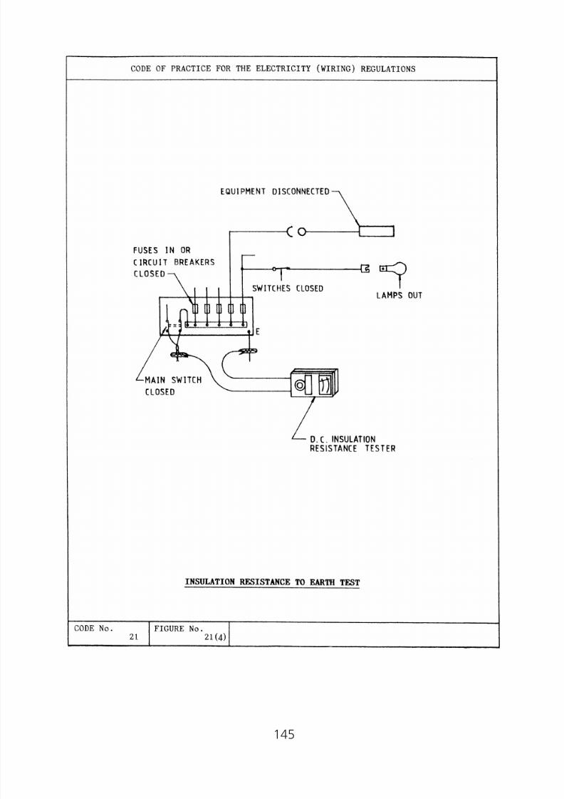
8/23/2019 Electricity Wiring
http://slidepdf.com/reader/full/electricity-wiring 145/337
145
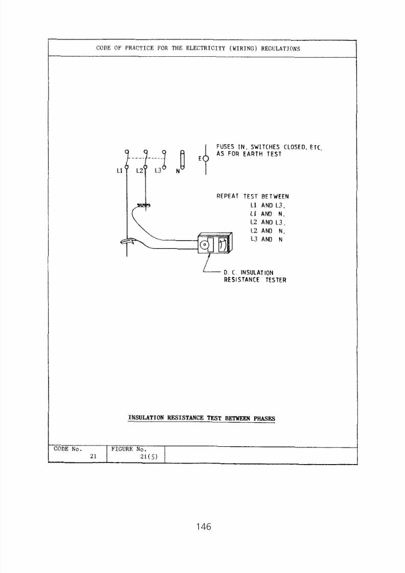
8/23/2019 Electricity Wiring
http://slidepdf.com/reader/full/electricity-wiring 146/337
146

8/23/2019 Electricity Wiring
http://slidepdf.com/reader/full/electricity-wiring 147/337
147

8/23/2019 Electricity Wiring
http://slidepdf.com/reader/full/electricity-wiring 148/337
Code 22 MAKING AND KEEPING OF RECORDS
22A Keeping of Records by the Owner of an Electrical Installation thatRequires Periodic Inspection, Testing and Certification
22B Making and Keeping of Records by a Registered Electrical Contractor
22C Types of Records
22D Checklists
(1) Checklists to be used
(2) Test sequence
(3) Checklist for high voltage installations
(4) Contents of checklists
148

8/23/2019 Electricity Wiring
http://slidepdf.com/reader/full/electricity-wiring 149/337
Code 22 MAKING AND KEEPING OF RECORDS
22A Keeping of Records by the Owner of an ElectricalInstallation that Requires Periodic Inspection, Testingand Certification
(a) It is the responsibility of the owner of a periodically tested electricalinstallation referred to in Regulation 20 (see Code 20) to keep thelatest test certificates and make available for inspection by theDirector.
(b) For high voltage fixed installation specified in Regulation 20(1)(c ) (seeCode 20A), the owner should also make available for inspection awritten summary of safety precautions taken for each event oftesting and maintenance work carried out on the installation.
22B Making and Keeping of Records by a RegisteredElectrical Contractor
(a) It is the responsibility of a registered electrical contractor to makeand keep proper records on all electrical works carried out by himand his employees for the lesser of 5 years or the time since hisregistration as an electrical contractor.
(b) The registered electrical contractor should also ensure that a copyof the records is made available to the owner of the electricalinstallation upon completion of work.
22C Types of Records
(a) For the purpose of Code 22B, a simple single line diagram withsymbols to Appendix 8 and simple test results against the lists ofitems to be inspected and tested detailed in a number of checklistsunder Code 22D together with test data recorded in the Schedule ofTest Results for Electrical Wiring (sample shown in Appendix 13) areacceptable as proper records.
(b) For the purpose of Code 22A(b), a record of the permit-to-worktogether with a maintenance log are acceptable.
22D Checklists
(1) Checklists to be used
Depending on the varying requirements as indicated in subparagraphs (a)and (b), records showing the results of the items of inspection and testingperformed according to the checklists numbered 1 to 4 in Appendix 13are generally acceptable.
149

8/23/2019 Electricity Wiring
http://slidepdf.com/reader/full/electricity-wiring 150/337
ChecklistsRequirements to be Used
(a) Periodic inspection and testing for a low voltageinstallation which was connected to supply:
(i) before 1.1.1985 1(ii) on or after 1.1.1985 and before 1.6.1992 1 and 2(iii) on or after 1.6.1992 1, 2 and 3
(b) Inspection and testing carried out upon completion of 1, 2, 3any electrical work for a low voltage installation and 4
(2) Test sequence
Where more than one of the checklists are to be used, the items to be
tested should follow the sequence stated in Code 21B(2)(a). The recordsagainst the items of the checklists used do not indicate the test sequence.
(3) Checklist for high voltage installations
For high voltage installations that are required to be inspected, testedand certified at least once every year, records showing the results of theitems of inspection and testing performed according to checklistnumbered 5 in Appendix 13 are generally acceptable. Recommendationfor testing of high voltage installations given in relevant recognised
standards and manufacturers for commissioning and periodic tests,where appropriate, should also be used.
(4) Content of checklists
(a) The checklists given in Appendix 13 contain a number of importantitems to be recorded after an inspection and testing and they aregiven to indicate generally the minimum requirements for recordpurposes only. The registered electrical worker carrying out the
inspections and tests should fill in test results and the rating of keyitems where indicated in the checklists; and must certify with dateon each individual item of inspection and testing listed. The use ofinitials for such certification is acceptable if a sample of the initialagainst a full signature of the registered electrical worker has beengiven in the records. Where any item listed in the checklists is notapplicable to the installation under inspection and testing, theregistered electrical worker should also certify it to be so. The use ofthe abbreviation ‘N/A’ is acceptable for this purpose. The registered
electrical worker should also ensure that all other relevant inspection
150

8/23/2019 Electricity Wiring
http://slidepdf.com/reader/full/electricity-wiring 151/337
and testing results are also properly recorded. All inspection andtesting results should be comprehensive; and where necessary, theymay be recorded separately and attached as annexes to the checklists.
(b) Checks stated in Code 21B(10) should be added to relevant check
lists for inspection and testing of installations in hazardousenvironment.
151

8/23/2019 Electricity Wiring
http://slidepdf.com/reader/full/electricity-wiring 152/337
Code 23 & Code 24 (Reserved for Future Uses)
152
8/23/2019 Electricity Wiring
http://slidepdf.com/reader/full/electricity-wiring 153/337
PART II
Code 25 GENERAL WORKMANSHIP
25A Wiring Installation Using Conduits(1) General requirements for installation of steel or PVC or plastic
conduit
(2) Wiring installation using steel conduit
(3) Wiring installation using PVC or plastic conduit
25B Wiring Installation Using Trunkings
(1) General requirements for installation of steel or PVC or plastictrunking
(2) Wiring installation using steel trunking
(3) Wiring installation using PVC or plastic trunking
25C Installation of Cables
(1) General requirements
(2) Installation of PVC insulated, PVC sheathed non-armoured cable
(3) Installation of armoured or metallic sheathed cable
(4) Use of flexible cable and flexible cord
25D Cable Joint and Cable Termination
(1) Cable joint
(2) Boxes for cable joint and cable termination
(3) General requirements for jointing and termination of cable(4) Straight-through joint
(5) Jointing of protective conductors
(6) Joints and terminations of non-armoured cables
(7) Jointing and termination of armoured cables
(8) Termination of bonding conductors
25E Installation of Socket Outlets
153

8/23/2019 Electricity Wiring
http://slidepdf.com/reader/full/electricity-wiring 154/337
Part II
Code 25 GENERAL WORKMANSHIP
25A Wiring Installation Using Conduits
(1) General requirements for installation of steel or PVC or plastic conduit
(a) Where a conduit crosses an expansion joint, special arrangementsshould be made to allow relative movement to occur on either sideof the expansion joint and an example is illustrated in Figure 25(1).A separate circuit protective conductor should be installed tomaintain an effective electrical continuity across the expansion joint.The circuit protective conductor should have a cross-sectional arearated to suit the largest live conductor drawn into the conduit.
(b) During the building construction, all open ends of the conduittermination, which are liable to be filled with water, moisture orother foreign matter, should be plugged with proper conduitstopping plugs; paper, rag or similar materials should not be used forthis purpose. Conduit boxes in similar circumstances should also besimilarly plugged to prevent concrete or plaster from entering theboxes during building construction.
(c ) Proper sealant for the prevention of accumulation of condensedmoisture should be applied to ceiling conduit outlets installed in acool space subject to the influx of warm air.
(d ) Saddles, for the support of surface conduits, should be providedthroughout the entire route at regular intervals. The spacingbetween adjacent saddles should not be greater than those given inTable 25(1).
(e) Cables should be drawn into a conduit by using drawn-in tape or
steel wire of the appropriate size. If cable lubricant is used, it shouldnot negatively interact with the cable they lubricate and should notincrease the flame spread or decrease the fire resistant properties ofthe cable.
(f ) All live conductors of the same circuit should be drawn into thesame conduit.
( g) The neutral cable of a lighting final circuit using single core cablesmay be routed in the conduit direct to the lighting point without
passing through the switch box.
(h) Adaptable boxes should be provided immediately after every twobends, or after a bend plus a total maximum straight run of 10metres or after a maximum straight run of 15 metres.
154

8/23/2019 Electricity Wiring
http://slidepdf.com/reader/full/electricity-wiring 155/337
(i ) Adjacent or parallel conduits cast in concrete should be separated bya spacing of not less than 25 mm.
(2) Wiring installation using steel conduit
(a) (i) Joint in steel conduits should be made by means of a solid
coupler into which the adjacent ends of the two conduitsshould be inserted and screwed up tightly in order to make theconduit run mechanically and electrically continuous. Exposedscrew threads should be painted with anti-corrosion paint.
(ii) Running couplings are not recommended.
(b) (i) Where a steel conduit terminates at a metal casing, theconnection should be made by a coupler or a brass adaptor forflexible conduit together with a brass male bush. The connection
between the flexible conduit and the adaptor should be securelyfixed and protected against ingress of moisture where required.Length of each flexible conduit should be kept to a minimum ofnot more than 1 m for general applications or 2 m inside falseceiling.
(ii) Where the metal casing is painted or enamelled, the electricalcontinuity between the conduit and the casing should beachieved by means of a separate protective conductor ofadequate size, connecting the earthing terminal of the conduit
and an earthing terminal inside the metal casing. A copperearthing piece placed between the bush and the metal casingmay be used as an earthing terminal of the conduit.
(c ) Conduit should not be bent more than 90 degrees. The internalradius of the bend should not be less than 2.5 times the outsidediameter of the conduit.
(3) Wiring installation using PVC or plastic conduit
(a) Conduit bends should have an internal radius of at least 4 times theoutside diameter of the conduit.
(b) The method of carrying out the conduit bends, conduit joints, fixingconduits to boxes without spouts, and the tools and materials to beused should be as recommended by the manufacturer of theconduits.
(c ) Due allowance should be made for the expansion of the PVC tubingat high temperatures. Expansion coupling or other fittings should beincluded in a straight run of 8 m or more. Saddles or clips should beof sliding fit.
(d ) Boxes for the suspension of luminaires or other equipment, whereconsiderable heat will be produced, should be fitted with steel insertclips. Plastic boxes used for suspension of luminaires or other
155

8/23/2019 Electricity Wiring
http://slidepdf.com/reader/full/electricity-wiring 156/337
equipment should be suitable for the suspended load at theexpected working temperature.
25B Wiring Installation Using Trunkings
(1) General requirements for installation of steel or PVC or plastic trunking(a) Individual pieces of trunking should be independently supported by
means of at least two fixed points per piece. On straight runs,supports for trunking should be fixed at regular intervals withmaximum spacings as given in Table 25(2). For runs with bends,supports should be fixed as near to the bend as practicable.
(b) Holes in trunking should be drilled, punched or cut by ring saw.After cutting, burrs and sharp edges on the trunking should be
removed to prevent abrasion of cables.(c ) Cables penetrating through trunking should be protected by
conduits except PVC insulated and sheathed cables if such cablesform part of a surface wiring system. In such case, the holes in thetrunking, through which such cables penetrate, should be fitted withsuitable rubber grommets or insulated bushes.
(2) Wiring installation using steel trunking
Connection between trunking and equipment should be made by means
of a standard flange coupling or an adaptor neck, fabricated or cast. Fordirect attachment of trunking to electrical equipment, the cable entriesshould be provided with smooth bore bushes or grommets and thereturn edge of the lid of the trunking should be left intact.
(3) Wiring installation using PVC or plastic trunking
(a) Trunking should have covers secured by purpose-made rivets. Coversof the clip-on type is acceptable for trunking sizes up to 100 mm ×
100 mm.
(b) The trunking should be fixed and supported in the normal way byscrews, but the holes in the trunking should be made oversize toallow for the movement of expansion. Washers should be usedunder the head of the screw which should not be tightened to itsfull extent.
25C Installation of Cables
(1) General requirements
(a) All cables should be run in a vertical or horizontal direction, wherepracticable, and should be secured flat on the surface of walls,columns, partitions or ceilings, etc. throughout the entire route.
156
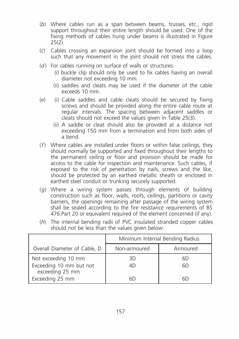
8/23/2019 Electricity Wiring
http://slidepdf.com/reader/full/electricity-wiring 157/337
(b) Where cables run as a span between beams, trusses, etc., rigidsupport throughout their entire length should be used. One of thefixing methods of cables hung under beams is illustrated in Figure25(2).
(c ) Cables crossing an expansion joint should be formed into a loop
such that any movement in the joint should not stress the cables.
(d ) For cables running on surface of walls or structures:
(i) buckle clip should only be used to fix cables having an overalldiameter not exceeding 10 mm.
(ii) saddles and cleats may be used if the diameter of the cableexceeds 10 mm.
(e) (i) Cable saddles and cable cleats should be secured by fixingscrews and should be provided along the entire cable route at
regular intervals. The spacing between adjacent saddles orcleats should not exceed the values given in Table 25(3).
(ii) A saddle or cleat should also be provided at a distance notexceeding 150 mm from a termination and from both sides ofa bend.
(f ) Where cables are installed under floors or within false ceilings, theyshould normally be supported and fixed throughout their lengths tothe permanent ceiling or floor and provision should be made for
access to the cable for inspection and maintenance. Such cables, ifexposed to the risk of penetration by nails, screws and the like,should be protected by an earthed metallic sheath or enclosed inearthed steel conduit or trunking securely supported.
( g) Where a wiring system passes through elements of buildingconstruction such as floor, walls, roofs, ceilings, partitions or cavitybarriers, the openings remaining after passage of the wiring systemshall be sealed according to the fire resistance requirements of BS476:Part 20 or equivalent required of the element concerned (if any).
(h) The internal bending radii of PVC insulated stranded copper cablesshould not be less than the values given below:
Overall Diameter of Cable, D
Minimum Internal Bending Radius
Non-armoured Armoured
Not exceeding 10 mm
Exceeding 10 mm but notexceeding 25 mm
Exceeding 25 mm
3D
4D
6D
6D
6D
6D
157
8/23/2019 Electricity Wiring
http://slidepdf.com/reader/full/electricity-wiring 158/337
(2) Installation of PVC insulated, PVC sheathed non-armoured cable
(a) Where protection is required for cables running up a wall from thefloor, a metal channel cover should be fixed to a minimum height of1.5 metres above finished floor level.
(b) Where cables pass through a building structure such as wall, columnor floor slab, the cables should be drawn through PVC or G.I. sleevesinserted into the building structure as illustrated in Figure 25(3) andsealed up with proper fire resisting material of the same FireResisting Period according to the requirements of BS 476:Part 20 orequivalent.
(c ) When cables are routed along or across steel joints, beams,stanchions, etc. they should be enclosed in steel or rigid PVCtrunking/conduit.
(d ) Rubber grommets or insulated bushes should be used to protect thenon-armoured cables passing through metal box or any other metalwork.
(e) Buckle clips should be:
(i) provided along the entire cable route at regular intervals notexceeding the spacing in Table 25(3);
(ii) provided at a distance not exceeding 75 mm from a terminationand from both sides of a bend;
(iii) fixed and secured by pins with wall plug inserted to a minimumdepth of 20 mm to the surface of wall, column, partition orceiling. The head of every pin should be level with the surfaceof the clip so that no damage to the sheath of the fixed cablescan occur; and every hole in the buckle clip should have a fixingpin.
(f ) The neutral conductor of a twin core cable for a lighting final circuitshould be looped through an insulated connector enclosed in the
moulded box or pattress accommodating the switch.
(3) Installation of armoured or metallic sheathed cable
(a) Cables buried direct in ground should be armoured or metalsheathed. Cables of Category 1 & 3 should be buried at a depth notless than 450 mm and cables of Category 4 should be buried at adepth not less than 750 mm. They should be protected by means ofcable cover tiles. The bottom of the cable trench should be firstcovered by a layer of sand or fine soil to a depth not less than the
diameter of the cable before the cables are laid. Another layer ofsand or fine soil, to a depth of 100 mm over the cables, should thenbe provided before the cable tiles are laid to protect the cablesthroughout entire route.
158

8/23/2019 Electricity Wiring
http://slidepdf.com/reader/full/electricity-wiring 159/337
0
0
(b) Unless otherwise advised by the cable manufacturer, a tensionreleasing section should be provided for every 100 metres of verticalcable run.
(4) Use of flexible cable and flexible cord
(a) Flexible cables or flexible cords for connections to portableappliances or equipment should have suitable length preferablybetween 1.5 m to 2 m.
(b) Exposed lengths of flexible cable or flexible cord used for finalconnections to fixed equipment or appliance should be as short aspossible.
(c ) Every non-flexible or flexible cable or flexible cord for use at lowvoltage shall comply with the appropriate recognised standard.
(d ) Where a flexible cord supports or partly supports a pendantluminaire, the maximum mass supported by the cord should notexceed the appropriate value indicated below, provided that thetension of the cord does not act directly on the termination to thewiring:
Nominal Cross-sectionalArea of Conductor
(mm2
)
Maximum Mass
(kg)0.50.751.0
235
25D Cable Joint and Cable Termination
(1) Cable joint
Cable joints of any type along cable runs in final circuits are not allowed.“Looping-in” wiring system should be used such that the cables orconductors are properly terminated at the junction box or equipment.
(2) Boxes for cable joint and cable termination
(a) Boxes for the termination and for joining of cables may be of castiron, or plastic shell with compound filled and of adequate size.
(b) Where hot compound filling is used, the box should be warmed
thoroughly before the compound is poured to allow total adhesionbetween the compound and the box. The compound should then beallowed to cool and be topped up before the box is closed. No airpockets should be allowed to form inside the box.
159

8/23/2019 Electricity Wiring
http://slidepdf.com/reader/full/electricity-wiring 160/337
(c ) Where cold compound with plastic shell is used, the complete jointing kit, including plastic shell, compound, insulating tape etc.should be from the same proprietary manufacturer. The jointingmethod and procedure as laid down by the manufacturer should bestrictly adhered to.
(d ) Where the box is of cast iron, it should be fitted with suitablearmouring clamps and glands; where the box is of plastic shell, itshould be fitted with suitably sized armour bond.
(3) General requirements for jointing and termination of cable
(a) All joints and terminations should have durable electrical continuityand adequate mechanical strength.
(b) Ferrules, compression connectors and bare portions of cable core
resulting from a jointing or terminating process should be insulatedwith an insulating tape or heat shrinkable tubing after completionthe jointing or terminating process. Such insulating tape or heatshrinkable tubing should have equal or better electrical andmechanical properties than those of the original insulation removed,and should be adhered to the cores etc. securely and permanently.The final thickness should be in smooth contour throughout thewhole length of the joint or termination.
(4) Straight-through joint (a) In a straight-through joint for copper conductors, the two
conductors should be butted together after the strands have beensoldered solid and should be jointed by means of a weak-backferrule, soldered to the cores. Soldering should be carried out bypouring tinman’s solder over the cores and the weak-back ferrule. Inno circumstances should direct flame from a blow lamp be used forsoldering.
(b) Prior to making a soldered joint for aluminium conductors, eachconductor should be cleaned by means of steel wool or similarabrasive and then tinned by pouring solder, especially made for usewith aluminium, over the cores. Both cores should then be insertedin a weak-back aluminium ferrule which should be closed. The twoaluminium cores to be jointed may be butted together. The solderingshould be completed by pouring the solder over the ferrule, afterapplying a layer of flux recommended by the cable manufacturer forthis purpose.
(c ) A compression joint should be made by inserting the conductorcores to be jointed into the opposite ends of a suitable type ofcompression jointing tube, which should have the correct size for theconductors. The tube should then be compressed onto the cores bymeans of a compressing tool. The tool used and the working
160
8/23/2019 Electricity Wiring
http://slidepdf.com/reader/full/electricity-wiring 161/337
procedure adopted should be as recommended by the compression joint or cable manufacturer.
(d ) Where specialist jointing kits are used, the complete kit should befrom the same manufacturer who specialises in manufacturingproducts for this purpose. The method and procedure adopted
should be strictly in accordance with the manufacturer’srecommendations.
(5) Jointing of protective conductors
(a) Protective conductors should be looped into earthing terminals ofexposed conductive parts or extraneous conductive parts. Straight joints in protective conductors should be avoided as far aspracticable. Tee-joints in protective conductors are acceptable.
(b) Tapes should be jointed by:(i) double riveting, or
(ii) suitable tape clamps (when clamps are used, the tape clampsshall each be provided with at least 4 screws or bolts), or
(iii) means of exothermic or thermic welding utilizing the hightemperature reaction of powdered copper oxide andaluminium, provided that the proper material and equipmentare used in accordance with the manufacturer’s recommendedprocess, or
(iv) terminal block of suitable size.
(6) Joints and terminations of non-armoured cables
(a) Non-armoured cables terminated at a moulded box or pattress, aluminaire or other fittings should have the overall protective sheathscarried into the moulded box or pattress, luminaire or other fittingsfor a minimum distance of 13 mm.
(b) The circuit protective conductor should be terminated at the
earthing terminal provided in the moulded box or pattress housingthe wiring accessories.
(c ) Where it is not required to terminate the circuit protective conductorin an accessory, the circuit protective conductor should be coiledaway from the live terminals or any bare conductors and should beinsulated and sleeved with a green-and-yellow PVC sleeve.
(d ) Jointing of circuit protective conductors of non-armoured cableshould be in the same manner as jointing live conductors.
(7) Jointing and termination of armoured cables(a) Cable armours should be terminated at the armouring clamps and
the inner sheath should pass through the gland.
161

8/23/2019 Electricity Wiring
http://slidepdf.com/reader/full/electricity-wiring 162/337
(b) Earth continuity across joints of a circuit protective conductor havingadequate cross-sectional area and of same material as the phaseconductors should be installed and connected to maintain theeffectiveness of the earth continuity across every cable joint of thearmoured cable.
(c ) PVC insulated armoured cables with copper or aluminiumconductors should be terminated in a gland fitted with an amourclamp. Provision should be made to enable a watertight sealbetween the gland and inner PVC sheath. The gland body should beprovided with an internal conical seating to receive the armourclamping cone and a clamping nut which should secure the armourclamping cone firmly to the armour wires ensuring that the armourwires are tightly clamped between the armour cone and conicalarmour seating. The spigot on the gland body should be threaded to
suit standard conduit accessories. A PVC shroud should be fitted tocover the body of the gland and the exposed armour wires.
(d ) (i) Terminating gland and armour clamp for cables with aluminiumconductors should be made from aluminium. Cores should beterminated in a hot tinned brass or copper lug, which should beshaped to suit the sector shape of the conductor. The coreshould be tinned, and then soldered into the lug. Alternatively acompression termination may be used. In such cases, the coresshould be inserted into the sleeve of an aluminium compressiontype cable lug. The sleeve should then be compressed onto thecores by means of a compressing tool. The tool used and theworking procedure adopted should be as recommended by thecable manufacturer.
(ii) Prior to connection to the terminal, the cable lug should bepainted with an anti-oxidising paste. The anti-oxidising pasteshould be suitable for preventing electrolytic action due tocontact between the aluminium lug and copper or brassterminal, for an indefinite period. Alternatively, copper/ aluminium bimetal cable lugs may be used.
(8) Termination of bonding conductors
(a) (i) A purpose-designed copper connector clamp should be used tobond the main equipotential bonding conductor to extraneousconductive parts of the non-electrical services, and should beused to bond supplementary bonding conductors to exposedconductive parts or extraneous conductive parts.
(ii) All contact surfaces should be clean and free from nonconducting materials, such as grease or paint, before theconnector clamp is installed.
162

8/23/2019 Electricity Wiring
http://slidepdf.com/reader/full/electricity-wiring 163/337
0
0
0
0
0
0
0
0
0
(b) For steel surface conduit installations, the supplementary bondingconductors should be terminated at the nearest conduit or conduitbox forming an integral part of the conduit installation.
(c ) (i) For concealed steel conduit installations, the supplementarybonding conductors should be terminated at a copper earthingterminal fitted inside a metal box forming an integral part of theconduit installation. For access to the concealed conduit, anarrangement similar to a telephone cord outlet is acceptable.
(ii) The metal conduit box should be located as near as possible tothe bonding position and the exposed part of thesupplementary bonding conductor should be made as short aspossible.
25E Installation of Socket Outlets(a) Wall-mounted socket outlets should be installed with a minimum clear
height of 150 mm from floor and 75 mm from surface top measuredfrom the bottom of the socket outlet.
(b) Socket outlets installed on floor surface should be suitably protected fromingress of water and from mechanical damage.
(c ) Socket outlets for household or similar use should be of shutteredtype.
(d ) A socket outlet should be installed as far away as practicable from watertap, gas tap or cooker in order to avoid danger.
Table 25(1)
Spacing of Supports for Conduits
Conduit Size (mm)
Maximum Distance between Supports (Metres)
Rigid Steel Rigid Plastic/PVC Pliable
Horizontal Vertical Horizontal Vertical Horizontal Vertical
Not exceeding 16
Exceeding 16 but notexceeding 25
Exceeding 25 but notexceeding 40
Exceeding 40
0.75
1.75
2.0
2.25
1.0
2.0
2.25
2.5
0.75
1.5
1.75
2.0
1.0
1.75
2.0
2.0
0.3
0.4
0.6
0.8
0.5
0.6
0.8
1.0
Notes: (1) The spacings tabulated above assume that the conduit is not exposed to
mechanical stress other than that due to the weight of the enclosed cables, theconduit and fittings.
(2) The above figures do not apply to a conduit used for supporting luminaires or otherequipment.
163

8/23/2019 Electricity Wiring
http://slidepdf.com/reader/full/electricity-wiring 164/337
0
0
0
0
0
0
0
0
0
0
0
0
0
0
0
Table 25(2)
Spacing of Supports for Cable Trunking (Steel or Plastic or PVC)
Cross-sectional Area of
Trunking (mm2
)
Maximum Distance between Support (Metres)
Steel Trunking Plastic/PVC Trunking
Horizontal Vertical Horizontal Vertical
Exceeding 300 but not exceeding700
Exceeding 700 but not exceeding1 500
Exceeding 1 500 but not exceeding2 500
Exceeding 2 500 but not exceeding5 000
Exceeding 5 000
0.75
1.25
1.75
3.0
3.0
1.0
1.5
2.0
3.0
3.0
0.5
0.5
1.25
1.5
1.75
0.5
0.5
1.25
2.0
2.0
Notes: (1) The spacings tabulated above assume that the trunking is not exposed tomechanical stress other than that due to the weight of the enclosed cables, thetrunking and fittings.
(2) The above figures do not apply to trunking which is used for supporting lightingfittings or other equipment.
Table 25(3)
Spacing of Supports for Cables in Accessible Positions
Overall diameterof cable‡
(mm)
Maximum spacing of clips (Metres)
Non-armoured rubber,PVC or lead-sheathed
cablesArmoured cables
Mineral insulatedcopper sheathed oraluminium sheathed
cables
Horizontal† Vertical† Horizontal† Vertical† Horizontal† Vertical†
Not exceeding 9
Exceeding 9 butnot exceeding 15
Exceeding 15 butnot exceeding 20
Exceeding 20 butnot exceeding 40
0.25
0.3
0.35
0.4
0.4
0.4
0.45
0.55
—
0.35
0.4
0.45
—
0.45
0.55
0.6
0.6
0.9
1.5
—
0.8
1.2
2.0
—
NOTE— For the spacing of supports for cables of overall diameter exceeding 40 mm, and forsingle-core cables having conductors of cross-sectional area 300 mm2 and larger, themanufacturer’s recommendations should be applied.
‡ For flat cables taken as the measurement of the major axis.
† The spacings stated for horizontal runs may be applied also to runs at an angle of more than30° from the vertical. For runs at an angle of 30° or less from the vertical, the vertical spacingsare applicable.
164

8/23/2019 Electricity Wiring
http://slidepdf.com/reader/full/electricity-wiring 165/337
165
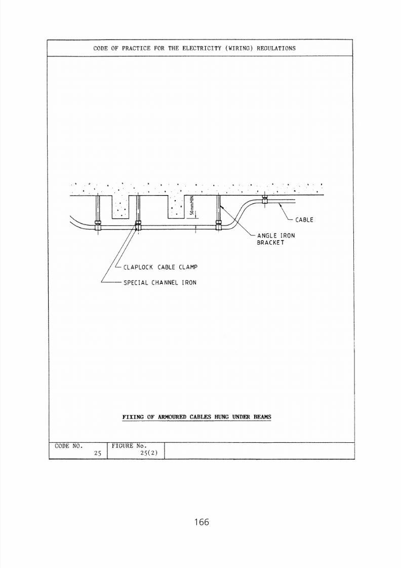
8/23/2019 Electricity Wiring
http://slidepdf.com/reader/full/electricity-wiring 166/337
166

8/23/2019 Electricity Wiring
http://slidepdf.com/reader/full/electricity-wiring 167/337
167
8/23/2019 Electricity Wiring
http://slidepdf.com/reader/full/electricity-wiring 168/337
Code 26 REQUIREMENTS FOR SPECIFICINSTALLATIONS AND EQUIPMENT
26A Domestic Installation and Appliance
(1) Supply connection to domestic appliance
(2) Electrical equipment in kitchens
(3) Electrical equipment in bathrooms
(4) Air-conditioners and space heaters
(5) Water heaters
(6) Electrical call bells and electric clocks
26B Busbar Trunking Distribution System
(1) General(2) Busbar casing
(3) Busbar
(4) Expansion unit
(5) Feeder unit
(6) Tap-off unit
(7) Busbar trunking accessories
26C Electric Motor(1) General
(2) Rating of circuits supplying electric motors
(3) Starting facilities of electric motors
26D Supply Connection to Transformers
26E Supply Connection to Welding Sets
26F Installation of Fluorescent and Gaseous Discharge Lamps
26G Installation of Category 3 Circuits
26H High Voltage Discharge Lighting Installation (Neon Signs)
(1) Requirements of circuits
(2) Means of isolation
(3) Fireman’s emergency switch
(4) Installation(5) Transformers
(6) Barrier for live parts
(7) Earthing
168

8/23/2019 Electricity Wiring
http://slidepdf.com/reader/full/electricity-wiring 169/337
26I Lightning Protection Installation
26J Rising Mains Installation
26K Temporary Supply Installation for Construction and Demolition Sites orRepair and Testing Purposes
(1) Scope
(2) General
(3) Design consideration
(4) Inspection, testing and maintenance
26L Hot Saunas Installation
(1) General
(2) Classification of zones(3) Basic protection and fault protection
(4) Selection and erection of equipment
26M Swimming Pools and Fountains Installation
(1) General
(2) Assessment of general characteristics
(3) Bonding
(4) Application of protective measures against electric shock(5) Selection and erection of equipment
26N Installation in Restrictive Conductive Locations
(1) Scope
(2) Basic protection and fault protection
(3) Basic protection
(4) Fault protection
26O Installation of Equipment Having High Earth Leakage Currents
26P Renewable Energy Power System
(1) Scope
(2) Selection and erection of installation
(3) Inspection, testing and maintenance
26Q Temporary Electrical Installation for Exhibitions, Shows, Stands and
Festive Lighting(1) Scope
(2) General
(3) Design consideration
169

8/23/2019 Electricity Wiring
http://slidepdf.com/reader/full/electricity-wiring 170/337
Code 26 REQUIREMENTS FOR SPECIFICINSTALLATIONS AND EQUIPMENT
26A Domestic Installation and Appliance
(1) Supply connection to domestic appliance
(a) For a single phase domestic appliance having a current ratingexceeding 13A to be used in an installation where only 5A and/or13A socket outlets are provided, or a domestic appliance having acurrent rating exceeding 15A to be used in an installation whereonly 5A and/or 15A socket outlets are provided, it should beconnected permanently (i.e. not through a plug socket) to a separateradial final circuit and should be controlled by a double-pole switchin a readily accessible position near the appliance.
(b) For supplying a single phase domestic appliance having a currentrating not exceeding 13A, the use of a radial or ring final circuitusing 13A socket outlets is acceptable.
(c ) For supplying a single phase domestic appliance having a currentrating not exceeding 5A or 15A, the use of a radial final circuit using5A or 15A socket outlet respectively, is acceptable.
(d ) Adequate number of socket outlets for supply connections to
domestic appliances is to be provided for each individual household.Table 26(1) recommends the acceptable minimum number of socketoutlets provided in various locations to afford the lowest quality ofservice.
(2) Electrical equipment in kitchens
(a) For a circuit arrangement using 13A socket outlets to Code 6E,separate circuits should be used for supply to electrical equipment inkitchen other than luminaires.
(b) Every cooking appliance having more than one boiling or cookingsurfaces and with a total current rating exceeding 15A should be fedfrom an exclusive radial final circuit and controlled by a double-poleswitch separate from the appliance and placed within 2 metres ofthe appliance.
(c ) Where two fixed or stationary cooking appliances are installed in oneroom of household premises, one switch may be used to controlboth appliances provided that neither appliance is placed more than
2 metres from the controlling switch.
(d ) The switch for the cooking appliance of subparagraphs (b) and (c )should be so positioned that the user does not have to lean acrossthe appliance in order to operate it.
170

8/23/2019 Electricity Wiring
http://slidepdf.com/reader/full/electricity-wiring 171/337
(3) Electrical equipment in bathrooms
(a) Except for SELV, for a circuit supplying equipment in a roomcontaining a fixed bath or shower, where the equipment issimultaneously accessible with exposed conductive parts of otherequipment or with extraneous conductive parts, the characteristicsof the protective devices and the earthing arrangements should besuch that, in the event of a fault to earth, disconnection occurswithin 0.4s. All circuits supplying electrical equipment with exposedconductive parts within 2.25m height above finished floor levelshould be protected by one or more residual current device (RCD)with a residual operating current not exceeding 30mA.
(b) Except for equipment supplied from a SELV circuit, in a roomcontaining a fixed bath or shower, supplementary equipotential
bonding to Code 11 should be provided between simultaneouslyaccessible exposed conductive parts of equipment, between exposedconductive parts and simultaneously accessible extraneousconductive parts, and between simultaneously accessible extraneousconductive parts.
(Note: Where the bathroom is in a building with a protectiveequipotential bonding system in accordance with Code11E, supplementary equipotential bonding may be omittedwhere all of the following conditions are met:
(i) All final circuits of the bathroom comply with therequirements for automatic disconnection according toCode 11B;
(ii) All final circuits have additional protection by means ofan RCD having the characteristics specified in Code11J;
(iii) All extraneous conductive parts of the bathroom areeffectively connected to the protective equipotential
bonding according to Code 11E.)(c ) Where electrical equipment is installed in the space below a bath,
that space should be accessible only by the use of a tool and, inaddition, the requirement of subparagraph (b) above should extendto the interior of that space.
(d ) Every switch or other means of electrical control or adjustmentshould be so situated as to be normally inaccessible to a personusing a fixed bath or shower. This requirement does not apply to:
(i) the insulating cords of cord-operated switches which complywith IEC 60669-1 or BS EN 60669-1 or equivalent;
(ii) mechanical actuators, with linkages incorporated insulatingcomponents, of remotely operated switches;
171

8/23/2019 Electricity Wiring
http://slidepdf.com/reader/full/electricity-wiring 172/337
(iii) controls and switches of water heaters and shower pumpswhich comply with the relevant requirements of appropriaterecognised standards;
(iv) switches supplied by SELV at a nominal voltage not exceeding12 V r.m.s. a.c. or d.c.;
(v) a shaver supply unit complying with subparagraph (e) below.
(e) In a room containing a fixed bath or shower, provision for theconnection of an electric shaver, toothbrush or similar light currentappliance can be by means of a shaver supply unit complying withBS EN 61558-2-5 or such a unit incorporated in a luminaire. Theearthing terminal of the shaver supply unit should be connected tothe protective conductor of the final circuit from which the supply isderived.
(f ) Surface wiring systems should not employ metallic conduit ormetallic trunking or an exposed metallic cable sheath or an exposedearthing or bonding conductor.
( g) Lampholders within a distance of 2.5 metres from the bath orshower cubicle should be constructed of or shrouded in an insulatingmaterial.
(h) No stationary equipment having heating elements which can betouched should be installed within reach of a person using the bath
or shower.
(i ) No electrical installation or equipment should be installed in theinterior of a bath tub or shower basin.
( j ) In a room containing a fixed bath or shower, the provision of socketoutlets should comply with IEC 60364-7-701 and be installedbeyond Zone 2* (i.e. 0.6m away from shower basin or bath tub)and the socket outlets should be protected by an RCD with aresidual operating current not exceeding 30mA. When a circuit
designer who is a Registered Electrical Worker for Grade A, B or Cconsiders it appropriate for the situations under consideration,additional safety measures may be used. These measures include theuse of a dedicated circuit or a dedicated circuit protected by anisolating transformer.
* Zone dimensions in bathrooms should be referred to Figure26(1)(a) and 26(1)(b)
(4) Air-conditioners and space heaters
(a) Fixed air-conditioners and space heaters should be fed by separateradial final circuits controlled by a fuse or miniature circuit breaker atthe distribution board.
172

8/23/2019 Electricity Wiring
http://slidepdf.com/reader/full/electricity-wiring 173/337
(b) Fixed air-conditioners and space heaters having a rating notexceeding 13A for a final circuit using 13A socket outlets or 15A fora final circuit using 15A socket outlets, may be connected via a plugand socket arrangement of adequate capacity. For this purpose, aswitched socket outlet is to be used.
(c ) A fixed air-conditioner or a space heater having a rating exceedingthat of subparagraph (b), should be connected to a terminal blockadjacent to it and controlled by a double-pole switch.
(5) Water heaters
(a) Electrode water heaters and boilers
(i) Every electrode boiler and electrode water heater should beconnected to an a.c. system only, and should be selected and
erected in accordance with the appropriate requirements of thisCoP.
(ii) The supply to the heater or boiler should be controlled by alinked circuit breaker arranged to disconnect the supply from allelectrodes simultaneously and provided with an overcurrentprotective device in each conductor feeding an electrode.
(iii) The earthing of the heater or boiler shall comply with therequirements of Code 11 and, in addition, the shell of theheater or boiler should be bonded to the metallic sheath and
armour, if any, of the incoming supply cable. The protectiveconductor should be connected to the shell of the heater orboiler and should comply with Code 11C(2).
(iv) Where an electrode water heater or electrode boiler is directlyconnected to a supply at a voltage exceeding low voltage, theinstallation should include a residual current device arranged todisconnect the supply from the electrodes on the occurrence ofa sustained earth leakage current in excess of 10% of the ratedcurrent of the heater or boiler under normal conditions of
operation, except that if in any instance a higher value isessential to ensure stability of operation of the heater or boiler,the value may be increased to a maximum of 15%. A time delaymay be incorporated in the device to prevent unnecessaryoperation in the event of imbalance of short duration.
(v) Where an electrode water heater or electrode boiler isconnected to a three phase low voltage supply, the shell of theheater or boiler should be connected to the neutral of thesupply as well as to the earthing conductor. The current carryingcapacity of the neutral conductor should be not less than thatof the largest phase conductor connected to the equipment.
173
8/23/2019 Electricity Wiring
http://slidepdf.com/reader/full/electricity-wiring 174/337
(vi) Except as provided by (vii) where the supply to an electrodewater heater or electrode boiler is single phase and oneelectrode is connected to a neutral conductor earthed by theelectricity supplier, the shell of the water heater or boiler shouldbe connected to the neutral of the supply as well as to the
earthing conductor.(vii) Where the heater or boiler is not piped to a water supply or in
physical contact with any earthed metal, and where theelectrodes and the water in contact with the electrodes are soshielded in insulating material that they cannot be touchedwhile the electrodes are live, a fuse in the phase conductor maybe substituted for the circuit breaker required under (ii) and theshell of the heater or boiler need not be connected to theneutral of the supply.
(b) Heaters for liquids or other substances, having immersed heatingelements
Every heater for liquid or other substance should incorporate or beprovided with an automatic device to prevent a dangerous rise intemperature.
(c ) Water heaters having immersed and uninsulated heating elements
(i) Every single phase water heater or boiler having an uninsulated
heating element immersed in the water should comply with therequirements of (ii) and (iii). This type of water heater or boileris deemed not to be electrode water heater or boiler.
(ii) All metal parts of the heater or boiler which are in contact withthe water (other than current carrying parts) should be solidlyand metallically connected to a metal water pipe through whichthe water supply to the heater or boiler is provided, and thatwater pipe should be connected to the main earthing terminalby means independent of the circuit protective conductor.
(iii) The heater or boiler should be permanently connected to theelectricity supply through a double-pole linked switch which iseither separate from and within easy reach of the heater orboiler or is incorporated therein and the wiring from the heateror boiler should be directly connected to that switch withoutuse of a plug and socket outlet; and, where the heater or boileris installed in a room containing a fixed bath, the switch shouldalso comply with Code 26A(3).
(iv) Before a heater or boiler of the type referred to in subparagraph
(c ) is connected, the electrical worker should confirm that nosingle-pole switch, non-linked circuit breaker or fuse is fitted inthe neutral conductor in any part of the circuit between theheater or boiler and the origin of the installation.
174

8/23/2019 Electricity Wiring
http://slidepdf.com/reader/full/electricity-wiring 175/337
(d ) Single phase domestic thermal storage or instantaneous waterheaters not exceeding 6 kilowatts should be connected to anindividual final circuit and be controlled by a double-pole switch ofadequate rating. If the water heater is installed in a bathroom, thedouble pole switch should be installed outside the bathroom in a
convenient position.(e) A thermal storage or instantaneous water heaters exceeding 30
ampere or having a current rating exceeding half of the maximumdemand of an installation in any one phase, should be connected toa three phase supply except when approved by the electricitysupplier.
(6) Electrical call bells and electric clocks
(a) (i) Call bell transformers should be double wound.(ii) Call bell transformers should be connected via a plug and
socket arrangement or via a connection unit or cable coupler.
(iii) Call bell pushes should be wired to the secondary windings atan extra low voltage.
(b) Electric clocks may be connected to a lighting circuit via a connectionunit or cable coupler provided that the current demand of the circuitdoes not exceed the rating of the overcurrent protective device.
26B Busbar Trunking Distribution System
(1) General
(a) The busbar trunking system should comply with IEC 60439-2 / BS EN60439-2 and should be properly supported.
(b) The busbar trunking system must be suitable for branch circuitconnections to the busbars by tap-off units or cable clampingdevices.
(c ) The cross-sectional area of phase and neutral conductors of thebusbars system should be selected taking into account the effects ofharmonic current that may be present in the distribution system.
(2) Busbar casing
(a) The casing of the busbar trunking system should be totally enclosed.It should be rigidly constructed from sheet steel galvanised or
suitably protected against corrosion of not less than 1.2 mm thickfor the width or height of the casing not exceeding 100 mm; andnot less than 1.5 mm thick for a width or height exceeding 100 mm.
175
8/23/2019 Electricity Wiring
http://slidepdf.com/reader/full/electricity-wiring 176/337
(b) Facilities should be incorporated in the busbar casing to provideaccess to the busbars at regular intervals throughout the entirelength. Removal of the cover for access facility should necessitate theuse of tools.
(3) Busbar (a) For busbar installation having a rated capacity not exceeding 400
amperes in each phase of a 3-phase 4-wire system, the associatedneutral busbars should have a cross-sectional area not less than thecross-sectional area of the phase busbar.
(b) For busbar installation having a rated capacity exceeding 400A ineach phase of a 3-phase 4-wire system, the associated neutralbusbar may have a cross-sectional area smaller than the cross
sectional area of the phase busbar if overcurrent detection isprovided for the neutral conductor, which is appropriate to thecross-sectional area of the conductor. This detection shall cause thedisconnection of the phase conductors but not necessarily theneutral conductor.
(c ) The joint part of the busbar, or contact part of the busbars in thecase of plug-in busbar trunking systems, should be electroplatedwith tin or other equivalent materials.
(d ) Drilling of all-insulated busbars for connection of cables are notacceptable.
(4) Expansion unit
Proper expansion unit should be provided where:
(a) both ends of the busbar trunking system are fixed, or
(b) the busbar trunking system is installed across a building expansion joint, or
(c ) the run of busbar exceeds 30 metres or as recommended by thebusbar manufacturer.
(5) Feeder unit
A proper feeder unit should be provided for each busbar trunking systemfor connection of incoming supply.
(6) Tap-off unit
(a) Proper tap-off unit should be used where a branch circuit is takenoff from the busbars.
176

8/23/2019 Electricity Wiring
http://slidepdf.com/reader/full/electricity-wiring 177/337
(b) Where protective devices are used separately for tapping-off, theyshould be provided adjacent to the tapping position for protection ofthe branch circuits.
(c ) Where conductors are used for connection to the busbars, theyshould have a current rating not less than that of the tap-off units.
(d ) Where plug-in tap-off units are used, mechanical interlocks shouldbe provided such that the tap-off unit cannot be inserted orremoved from the busbar trunking unless it is in the ‘OFF’ position.
(e) Where cutout fuses are used for tap-off supply from busbars, theyshould be fitted with an insulated carrier to avoid danger duringreplacement or withdrawal.
(7) Busbar trunking accessories
(a) Accessories such as bends, tees, feeder and tap-off units for busbartrunking system should be purpose-made.
(b) Bends, tees and intersection units should be designed andmanufactured to suit the particular type of busbar system. Thecasing should have a cross-sectional area not less than that of thebusbar casing.
26C Electric Motor
(1) General
(a) Every electrical motor having a rating exceeding 0.37 kW should beprovided with control equipment incorporating means of protectionagainst overload in the motor.
(b) This requirement does not apply to motors incorporated in anitem of current using equipment complying as a whole with anappropriate recognised standard.
(2) Rating of circuits supplying electric motors
(a) All equipment, including cable of every electrical part of the circuitcarrying the starting, accelerating and load currents of a motorshould be suitable for a current at least equal to the full load currentrating of the motor. Where the motor is intended for intermittentduty and for frequent stopping and starting, account should betaken of any cumulative effects of the starting or braking currentsupon the temperature rise of the equipment of the circuit.
(b) The rating of the circuit supplying a slip ring or a commutatorinduction motor should be suitable for the starting and loadconditions of the motor.
177

8/23/2019 Electricity Wiring
http://slidepdf.com/reader/full/electricity-wiring 178/337
.0
.0
.0
.0
(3) Starting facilities of electric motors
(a) The starting facilities of induction motors of various sizes shouldrestrict the starting current of the motors to maximum acceptablelimits as required by the electricity supplier.
(i) Low voltage induction motors(A) The choice of motor size and maximum acceptable startingcurrent should be in accordance with the following table:
Supply ArrangementMotor Size (M) in
KilowattsNo. ofPhases
Maximum StartingCurrent (in Multiple of
Full Load Current)
From ElectricitySupplier’s OverheadLine System
M ഛ 1.51.5 Ͻ M Ͻ 3.83.8 ഛ M ഛ 11
1-phase3-phase3-phase
662.5
From ElectricitySupplier’sNon-overhead LineSystem
M ഛ 2.22.2 Ͻ M Ͻ 1111 ഛ M ഛ 55
1-phase3-phase3-phase
662.5
(B) Motors exceeding the limits stipulated in the table abovemust be approved in writing by the electricity supplier.
(ii) Synchronous motors and high voltage motors should only beinstalled by special arrangement with the electricity supplier.
(b) Except where failure to start after a brief interruption would be likelyto cause greater danger, motors should be provided with means toprevent automatic restarting after the stoppage due to drop involtage or failure of supply, where unexpected restarting of themotor might cause danger. These requirements do not precludearrangements for starting a motor at intervals by an automaticcontrol device, where other adequate precautions are taken againstdanger from unexpected restarting.
26D Supply Connection to Transformers
(a) Where an autotransformer is connected to a circuit having a neutralconductor, the common terminal of the winding should be connected tothe neutral conductor.
(b) Where a step-up transformer is used, a linked switch should be providedfor disconnecting the transformer from all live conductors (i.e. phase andneutral conductors) of the supply.
178

8/23/2019 Electricity Wiring
http://slidepdf.com/reader/full/electricity-wiring 179/337
26E Supply Connection to Welding Sets
Welding sets having a current rating exceeding 30A single phase or half of themaximum demand of an installation in any one phase should be permanentlyconnected to the mains on a 3-phase supply. Exposed conductive parts ofwelding sets must be effectively connected to earth.
26F Installation of Fluorescent and Gaseous DischargeLamps
(a) Capacitors and chokes should normally be fitted inside the luminaire.Where they are fitted separately, they should be mounted in a metal box.Precautions should be taken to prevent the components fromoverheating, e.g. by the provision of adequate ventilation.
(b) The type and size of cables should be properly selected with due regardto the ambient temperature, the inrush current and high voltagesgenerated during starting. The neutral conductor in every discharge lampcircuit should have a cross-sectional area not less than that of the phaseconductor.
26G Installation of Category 3 Circuits
Electrical installation of Category 3 circuits should comply with therequirements of the relevant authority in respect to fire protection aspects.
26H High Voltage Discharge Lighting Installation (NeonSigns)
(1) Requirements of circuits
(a) High voltage discharge lighting installation should not be connected
to the electricity supply through a plug and socket arrangement.(b) Circuits should be capable of carrying the total steady load current
of the lamps, any associated gear and also their harmonic currents.
(c ) Where exact information on the associated gear is not available, theproduct of the rated wattage of the associated gear and amultiplying factor of not less than 1.8 shall be taken as the demandof the installation in volt-amperes.
(d ) The cross-sectional area of the neutral conductor in every discharge
lighting circuit should not be less than that of the phase conductor.
(e) Every switch for a discharge lighting circuit should be identified witha permanent label and should have a normal current rating not less
179

8/23/2019 Electricity Wiring
http://slidepdf.com/reader/full/electricity-wiring 180/337
than the product of the total steady current which it is required tocarry and a multiplying factor of 1.8.
(2) Means of isolation
One or more of the following means should be provided inside the
building for the isolation from all live conductors of the supply to self-contained luminaires or every circuit supplying high voltage luminaires,and such means should comply with requirements of Code 8B(2):
(a) an interlock on the self-contained luminaire, so arranged that beforeaccess can be made to live parts, the supply is automaticallydisconnected, such means being additional to the switch normallyused for controlling the circuit, or
(b) a switch having a lock or removable handle, or a distribution board
which can be locked, and with such arrangements to prevent therestoration of the supply by unauthorised persons. Where aninstallation comprises more than one such switch or distributionboard, all keys and removable handles should be noninterchangeable.
(3) Fireman’s emergency switch
A fireman’s emergency switch complying with requirements of Code8B(4), should be provided for every exterior or interior high voltagelighting installation which is operated unattended. Such firemen’semergency switch should:
(a) be arranged to isolate the installation from all live conductors of thesupply, except that it need not isolate the neutral conductor of a3-phase 4-wire supply;
(b) be fixed in a conspicuous position, reasonably accessible to firemenat not less than 2.7 metres and not more than 3.0 metres above thefloor or the ground;
(c ) be clearly marked to indicate the installation or part of theinstallation which they control, where more than one fireman’sswitch is installed in any one building;
(d ) preferably be provided with a catch so designed as to prevent theswitch being inadvertently or accidentally returned to the ‘ON’position;
(e) for exterior installation, be outside the building and as near as
possible vertically below the electrical discharge lamp(s). Alternativelya notice indicating the position of the switch shall be placed directlybelow the electrical discharge lamp(s) and a nameplate should befixed near the switch so as to render it clearly distinguishable. Aninstallation in a closed market or in an arcade is deemed to be an
180

8/23/2019 Electricity Wiring
http://slidepdf.com/reader/full/electricity-wiring 181/337
1 1
1 1
1
exterior installation and a temporary installation in a permanentbuilding used for exhibitions is considered as an interior installationand not an exterior installation.
(f ) for interior installations, be near the main entrance to the building oralternatively in a position to be agreed with the electricity supplierand the Fire Services Department.
(4) Installation
(a) The luminous discharge tubes should be substantially supported at asufficient distance from the sign face to ensure no arcing from thetube to any other portion of the sign could occur under normalcondition, and be so installed as to be free from contact withinflammable material except that rubber glands are permitted where
a weather proof construction is desirable.(b) Tubes should not be unduly exposed to mechanical damage.
(c ) Ancillary equipment for high voltage installations includinginductors, capacitors, resistors and transformers should either betotally enclosed in a rigid and effectively earthed metal container(which may form part of the luminaires), or alternatively should beplaced in a suitably ventilated enclosure of incombustible material orof fire resisting construction.
(d ) High voltage cables and conductors should be supported at intervalsnot exceeding the appropriate values stated in the following table.Support for insulated-and-braided cables and for bare conductorsshould be of non-ignitable, non-hygroscopic insulating material, e.g.glass or glazed porcelain.
Type of Cable or Conductor
Spacing of Supports
Horizontal(mm)
Vertical(mm)
Bare conductor 500 500
Insulated-and-braided cables 500 800
Metal sheathed, non-armoured cables 800 1 250
Armoured cables 1 000 1 500
(e) Every inductor and high reactance transformer should be installed as
near as practicable to its associated electric discharge tube.(f ) The transformer, discharge tube and other parts of high voltage
circuits should be located out of reach.
181

8/23/2019 Electricity Wiring
http://slidepdf.com/reader/full/electricity-wiring 182/337
(5) Transformers
(a) Every transformer should be double wound with windings insulatedwith material to a minimum quality of class E insulation andtropicalised.
(b) One point of the secondary winding of every transformer should beconnected to an earthing terminal on the body of the container.
(c ) The secondary voltage of every transformer should not exceed 5 kVr.m.s. to earth on open circuit.
(d ) Every high voltage circuit supplied from a transformer having a ratedinput exceeding 500 watts should be provided with means forautomatic disconnection of the supply at the supply end of thetransformer in the event of a fault current exceeding 20 percent of
the normal steady current in the circuit.(e) The rating plate of every transformer should carry:
(i) the maker’s name,
(ii) open-circuit secondary voltage,
(iii) rated secondary current,
(iv) rated primary voltage, and
(v) rated primary current.
(6) Barrier for live parts
(a) All live parts, including all conductors but excluding the tubes exceptin the neighbourhood of their terminals, should be provided witheffective barriers of earthed metal or insulating materials, ormechanical strength adequate to withstand the conditions of normalservice, or alternatively, for installations on the exterior of a building,such live parts may be so situated as to be accessible only toresponsible persons.
(b) Barriers made of insulating material used for this purpose should benon-hygroscopic, anti-tracking and substantially non-ignitable. Glassbarriers may be used only if so situated as to be accessible only toresponsible persons.
(7) Earthing
Exposed conductive parts and metalwork inclusive of metal frames ofhigh voltage discharge lighting signs, as well as sheaths of cables shouldbe permanently connected to protective conductors and effectivelyearthed.
182

8/23/2019 Electricity Wiring
http://slidepdf.com/reader/full/electricity-wiring 183/337
26I Lightning Protection Installation
Lightning protection installations should be installed to IEC 62305, BS EN62305, AS/NZS 1768, NFPA 780 or equivalent.
26J Rising Mains Installation
(a) Any building of more than four floors including the ground floor shouldbe provided with 3-phase electrical rising mains with a 3-phase 4-wiretee-off at each floor unless otherwise agreed by the electricity supplier.
(b) The design of the rising mains installation should be agreed by theelectricity supplier.
(c ) Separate riser earthing conductors should be provided to earth all units
therein. The minimum cross-sectional area of riser earthing conductorshould be 70 mm2 for copper and 150 mm2 for aluminium.
(d ) The consumer’s main connection between the electricity supplier’s meterand the consumer’s main switch should be installed and maintained bythe consumer and should be not less than 4 mm2 stranded copperconductors.
(e) In multi-consumer premises a device capable of both isolating andswitching the full load current of the whole installation should be
provided for each consumer at a position immediately before theelectricity supplier’s meter. For a single phase installation this deviceshould be of double-pole type interrupting all live conductors.
(f ) In multi-consumer premises no part of the communal installation shouldpass through any individual consumer’s unit within the building.
26K Temporary Supply Installation for Construction andDemolition Sites or Repair and Testing Purposes
(1) Scope
The particular requirements of this Code should apply to temporaryinstallation providing supplies during the execution of construction ordemolition works, or for repair and testing purposes. This type ofinstallation should not be used as permanent supply. Approval should beobtained from the electricity supplier
(2) General
(a) This type of installation should comply with the requirement of theWiring Regulations.
183

8/23/2019 Electricity Wiring
http://slidepdf.com/reader/full/electricity-wiring 184/337
(b) Electrical apparatus and wiring installations in construction sites maybe subjected to extreme abuse and the equipment to be used shouldwithstand the particularly adverse conditions. Correct installation ofoverhead line or underground cable system, circuit protection,earthing arrangement will be essential as well as frequent inspection
and testing to such installations.
(3) Design consideration
(a) Operating voltage
(i) Mains voltage
• Three phase—380 volts 4-wire is the standard three phasemains supply voltage for construction sites.
• Single phase—220 volts 2-wire is the standard single phase
mains supply voltage.(ii) Lighting accessible to public
Road work and site lighting which is connected to mains supplysystem and accessible to general public should be operated at110 volts obtained by use of an isolating transformer having thecentre tap of the secondary winding earthed so that the normalvoltage of circuit to earth does not exceed 55 volts.
(b) Selection and erection of installation
(i) Cable circuits• Where risk of mechanical damage is slight, the installationcan be carried out in PVC insulated cable. However wheredamage is likely to occur armoured cables should be used.
• All cables that are likely to be frequently moved in normal useshould be flexible cables.
• All cables shall be suitably supported and properly fixed.
(ii) Overhead line circuits
• Where carrier wire is used to support cable suspendedbetween poles, Codes 16H and 16I should be complied with.
• Cables crossing carriage ways should be supported by steelpoles of suitable construction to withstand wind of typhoonforce. Wooden supports of adequate strength will bepermitted in other locations.
(iii) Minimum clearance between ground and line should complywith Code 16E(2).
(iv) Where steel poles are used, installation methods shall comply
with Codes 16B and 16I.
184

8/23/2019 Electricity Wiring
http://slidepdf.com/reader/full/electricity-wiring 185/337
(v) Where wooden poles are used, all stay wires should beinsulated to prevent danger from leakage. A stay insulatorplaced at a height not less than 3.1 m from ground should beinstalled.
(c ) Protection of circuits
(i) Protection apparatus with adequate interrupting capabilityshould be provided for all main and sub-circuits againstovercurrent and earth faults.
(ii) Discrimination between protection devices of main and sub-circuits should be allowed where necessary.
(d ) Protection against earth leakage
(i) This type of installation should be provided with a ResidualCurrent Device (RCD) at main intake position to affordprotection against earth leakage.
(ii) The operating current of the RCD to be used should be suchthat when its value in amperes is multiplied by the earth faultloop impedance in ohms, the product does not exceed 25 volts.
(iii) Circuits supplying socket outlet should be protected by RCDhaving a rated residual operating current not exceeding30 mA.
(iv) An earthing conductor should connect the consumer’s main
earthing terminal to an effective earth electrode. The size of theearthing conductor should be in accordance with Code 11H.
(v) In addition to the item (iv), the consumer should provide a bondbetween electricity supplier’s metal sheath cable andconsumer’s main earthing terminal. The size of bondingconductor should be in accordance with Code 11G(b).
(e) Precaution against danger
(i) All equipment and cables exposed to weather, corrosiveatmosphere or damp conditions should be of the weather prooftype or contained in weather proof enclosures suitable for theconditions.
(ii) Socket outlets, plugs and cable couplers should comply with IEC60309-2 with the colour identification coding as follows:
• 380/415 V, 50/60 Hz — Red;
• 220/250 V, 50/60 Hz — Blue;
• 110/130 V, 50/60 Hz — Yellow.
(iii) Lampholders should be of the all-insulated pattern and capable
of withstanding rough usage. Handlamps must be made ofinsulated material with bulbs efficiently guarded againstbreakage.
185

8/23/2019 Electricity Wiring
http://slidepdf.com/reader/full/electricity-wiring 186/337
(f ) Supply from generator set
Where the electricity supply is obtained from a generator set, theTN-S earthing system should be used.
(4) Inspection, testing and maintenance
An owner of the temporary installation should ensure that the electricalequipment and apparatus are maintained in a safe and proper workingcondition at all times.
A registered electrical worker should be appointed to be responsible forthe safety and any alteration or extension of the installation. The name,designation and contact telephone number of such person should bepermanently displayed close to the main switch of the installation.
A separate log book recording regular checks, maintenance, repair,extension and alteration should be provided for inspection by the Directorand the electricity supplier.
26L Hot Air Saunas Installation
(1) General
The particular requirements of this Code should apply to:
(a) sauna cabins erected on site, e.g. in a location or in a room;(b) the room where the sauna heater is, or the sauna heating appliances
are installed. In this case the whole room is considered as the sauna.
The requirements of this Code do not apply to prefabricated sauna cabinscomplying with a relevant equipment standard.
(2) Classification of zones
The zones specified below should be taken into account (see Figure
26(2)):
(a) Zone 1 is the volume containing the sauna heater, limited by thefloor, the cold side of the thermal insulation of the ceiling and avertical surface circumscribing the sauna heater at a distance 0.5mfrom the surface of the heater. If the sauna heater is located closerthan 0.5m to a wall, then Zone 1 is limited by the cold side of thethermal insulation of that wall.
(b) Zone 2 is the volume outside Zone 1, limited by the floor, the cold
side of the thermal insulation of the walls and a horizontal surfacelocated 1.0m above the floor.
186

8/23/2019 Electricity Wiring
http://slidepdf.com/reader/full/electricity-wiring 187/337
(c ) Zone 3 is the volume outside Zone 1, limited by the cold side of thethermal insulation of the ceiling and walls and a horizontal surfacelocated 1.0m above the floor.
(3) Basic protection and fault protection
(a) The protective measures of obstacles and placing out of reach arenot permitted.
(b) The protective measures of non-conducting locations and earth-freelocal equipotential bonding are not permitted.
(c) Additional protection should be provided for all circuits of the sauna,by the use of one or more RCDs having the characteristics specifiedin Code 11J. RCD protection need not be provided for the saunaheater unless such protection is recommended by the manufacturer.
(d ) Where SELV or PELV is used, whatever the nominal voltage, basicprotection should be provided by:
(i) basic insulation of live parts such that they are completelycovered with insulation which can only be removed bydestruction, or
(ii) barriers or enclosures affording a degree of protection of atleast IPXXB or IP2X.
(4) Selection and erection of equipment (a) All equipment should have at least the degree of protection of IPX4.
If cleaning by use of water jets may be reasonably expected,electrical equipment should have a degree of protection of at leastIPX5.
(b) In Zone 1, only the sauna heater and equipment belonging to thesauna heater should be installed.
In Zone 2, there is no special requirement concerning heat resistance
of equipment.
In Zone 3, equipment should withstand a minimum temperature of125°C and the insulation and sheaths of cables should withstand aminimum temperature of 170°C.
(c ) The wiring system should be preferably installed outside the zones,i.e. on the cold side of the thermal insulation. If the wiring systemis installed on the warm side of the thermal insulation in Zones 1 or3, it should be heat-resisting. Metallic sheaths and metallic conduits
should not be accessible in normal use.(d ) Switchgear and controlgear which forms part of the sauna heater
equipment or of other fixed equipment installed in Zone 2 may beinstalled within the sauna room or cabin in accordance with the
187

8/23/2019 Electricity Wiring
http://slidepdf.com/reader/full/electricity-wiring 188/337
manufacturer’s instructions. Other switchgear and controlgear, e.g.for lighting, should be placed outside the sauna room or cabin.Socket outlets should not be installed within the sauna room orcabin.
(e) Sauna heating appliances should comply with BS EN 60335-2-53and be installed in accordance with the manufacturer’s instructions.
26M Swimming Pools and Fountains Installation
(1) General
The particular requirements of this Code should apply to the basins ofswimming pools, the basins of fountains and the basins of paddling poolsand their surrounding zones where, in normal use, the risk of electric
shock is increased by a reduction in body resistance and contact of thebody with earth potential.
Special requirements may be necessary for swimming pools for medicalpurposes.
(2) Assessment of general characteristics
Figures 26(3), 26(4), 26(5) and 26(6) illustrate the zone dimensions ofswimming pools/fountains/paddling pools.
Zone 0 is the interior of the basin of the swimming pool or fountainincluding any recesses in its walls or floors, basins for foot cleaning andwaterjets or waterfalls and the space below them.
Zone 1 is limited by:
(a) Zone 0,
(b) a vertical plane 2 m from the rim of the basin,
(c ) the floor or surface expected to be occupied by persons, and
(d ) the horizontal plane 2.5 m above the floor or the surface expectedto be occupied by persons.
Where the swimming pool or fountain contains diving boards, springboards, starting blocks, chutes or other components expected to beoccupied by persons, Zone 1 comprises the zone limited by:
(a) a vertical plane situated 1.5 m from the periphery of the divingboards, spring boards, starting blocks, chutes and other components
such as accessible sculptures, viewing bays and decorative basins,and
(b) the horizontal plane 2.5 m above the highest surface expected to beoccupied by persons.
188
8/23/2019 Electricity Wiring
http://slidepdf.com/reader/full/electricity-wiring 189/337
Zone 2 is limited by:
(a) the vertical plane external to Zone 1 and a parallel plane 1.5 m fromthe former,
(b) the floor or surface expected to be occupied by persons, and
(c ) the horizontal plane 2.5 m above the floor or surface expected to beoccupied by persons.
There is no Zone 2 for fountains.
(3) Bonding
All extraneous conductive parts in Zones 0, 1 and 2 should be connectedby supplementary equipotential bonding conductors to the protective
conductors of exposed conductive parts of equipment situated in theseZones.
(4) Application of protective measures against electric shock
(a) Except for fountains as stated in Code 26M(6), in Zone 0 onlyprotection by SELV at a nominal voltage not exceeding 12V a.c.r.m.s. or 30V ripple-free d.c. is permitted, the source for SELV beinginstalled outside Zones 0, 1 and 2.
(b) Except for fountains as stated in Code 26M(6), in Zone 1 onlyprotection by SELV at a nominal voltage not exceeding 25V a.c.r.m.s. or 60V ripple-free d.c. is permitted, the source for SELV beinginstalled outside Zones 0, 1 and 2.
(c ) Equipment for use in the interior of basins which is only intended tobe in operation when people are not inside Zone 0 should besupplied by a circuit protected by:
• SELV, the source for SELV being installed outside Zones 0, 1 and
2. However, it is permitted to install the source for SELV inZone 2 if its supply circuit is protected by an RCD having thecharacteristics specified in Code 11J, or
• automatic disconnection of supply, using an RCD having thecharacteristics specified in Code 11J, or
• electrical separation, the source for electrical separation supplyingonly one item of current using equipment and being installedoutside Zones 0, 1 and 2. However, it is permitted to install thesource in Zone 2 if its supply circuit is protected by an RCD having
the characteristics specified in Code 11J.(d ) In Zone 2, one or more of the following protective measures should
be employed:
189
8/23/2019 Electricity Wiring
http://slidepdf.com/reader/full/electricity-wiring 190/337
• SELV, the source for SELV being installed outside Zones 0, 1 and2. However, it is permitted to install the source for SELV in Zone2 if its supply circuit is protected by an RCD having thecharacteristics specified in Code 11J;
• Automatic disconnection of supply, using an RCD having the
characteristics specified in Code 11J;• Electrical separation, the source for electrical separation supplying
only one item of current using equipment and being installedoutside Zones 0, 1 and 2. However, it is permitted to install thesource in Zone 2 if its supply circuit is protected by an RCD havingthe characteristics specified in Code 11J.
(5) Selection and erection of equipment
(a) Degree of protection of enclosures
Equipment should have the following minimum degrees ofprotection or equivalent:
(i) in Zone 0 – IPX8
(ii) in Zone 1 – IPX4
– IPX5 where water jets are likely to occur forcleaning purposes
(iii) in Zone 2 – IPX2 for indoor locations
– IPX4 for outdoor locations
– IPX5 where water jets are likely to occur forcleaning purposes.
(b) Wiring systems
(i) In Zones 0, 1 and 2, any metallic sheath or metallic covering ofa wiring system should be connected to the supplementaryequipotential bonding. Cables should preferably be installed inconduits made of insulating material.
(ii) In Zones 0 and 1, a wiring system should be limited to thatnecessary to supply equipment situated in these Zones.
(iii) Junction box should not be installed in Zones 0 and 1, but incase of SELV circuits it is permitted to install junction boxes inZone 1.
(c ) Switchgear and controlgear
(i) In Zones 0 and 1, switchgear or controlgear should not beinstalled.
(ii) In Zones 0 or 1, a socket outlet should not be installed.(iii) In Zone 2, a socket outlet or a switch is permitted only if the
supply circuit is protected by one of the following protectivemeasures:
190
8/23/2019 Electricity Wiring
http://slidepdf.com/reader/full/electricity-wiring 191/337
• SELV, the source of SELV being installed outside Zones 0, 1and 2. However, it is permitted to install the source of SELVin Zone 2 if its supply circuit is protected by a RCD having thecharacteristics specified in Code 11J;
• Automatic disconnection of supply, using an RCD having the
characteristics specified in Code 11J;• Electrical separation, the source for electrical separation
supplying only one item of current using equipment, or onesocket outlet, and being installed outside Zones 0, 1 and 2.However, it is permitted to install the source in Zone 2 if itssupply circuit is protected by an RCD having thecharacteristics specified in Code 11J.
(iv) For a swimming pool where it is not possible to locate a socketoutlet or switch outside Zone 1, a socket outlet or switch,preferably having a non-conductive cover or coverplate, ispermitted in Zone 1 if it is installed outside (1.25 m) from theborder of Zone 0, is placed at least 0.3 m above the floor, andis protected by:
• SELV, at a nominal voltage not exceeding 25V a.c. r.m.s. or60V ripple-free d.c., the source for SELV being installedoutside Zones 0 and 1, or
• automatic disconnection of supply, using an RCD having the
characteristics specified in Code 11J, or• electrical separation for a supply to only one item of currentusing equipment, the source for electrical separation beinginstalled outside Zones 0 and 1.
(d ) Other equipment
(i) In Zones 0 and 1, it is only permitted to install fixed currentusing equipment specifically designed for use in a swimmingpool.
(ii) Equipment which is intended to be in operation only whenpeople are outside Zone 0 may be used in all zones providedthat it is supplied by a circuit protected according tosubparagraph (4) above.
(iii) It is permitted to install an electric heating unit embedded in thefloor, provided that it:
• is protected by SELV, the source of SELV being installedoutside Zones 0, 1 and 2. However, it is permitted to installthe source of SELV in Zone 2 if its supply circuit is protected
by an RCD having the characteristics specified in Code 11J, or• incorporates an earthed metallic sheath connected to the
supplementary equipotential bonding specified insubparagraph (3) above and its supply circuit is additionally
191
8/23/2019 Electricity Wiring
http://slidepdf.com/reader/full/electricity-wiring 192/337
protected by an RCD having the characteristics specified inCode 11J, or
• is covered by an embedded earthed metallic grid connectedto the supplementary equipotential bonding specified insubparagraph (3) above and its supply circuit is additionally
protected by an RCD having the characteristics specified inCode 11J.
(iv) A luminaire for use in the water or in contact with the watershould be fixed and comply with BS EN 60598-2-18.Underwater lighting located behind watertight portholes, andserviced from behind, should comply with the appropriate partof BS EN 60598 and be installed in such a way that nointentional or unintentional conductive connection between anyexposed conductive part of the underwater luminaires and any
conductive parts of the portholes can occur.(v) Fixed equipment designed for use in swimming pools and other
basins (e.g. filtration systems, jet stream pumps) and supplied atlow voltage is permitted in Zone 1, subject to all the followingrequirements being met:
• The equipment should be located inside an insulatingenclosure providing at least Class II or equivalent insulationand providing protection against mechanical impact ofmedium severity (AG2);
• The equipment should be accessible only via a hatch (or adoor) by means of a key or a tool. The opening of the hatch(or door) should disconnect all live conductors. The supplycable and the main disconnecting means should be installedin a way which provides protection of Class II or equivalentinsulation;
• The supply circuit of the equipment should be protected bySELV at a nominal voltage not exceeding 25V a.c. r.m.s. or
60V ripple-free d.c., the source of SELV being installedoutside Zones 0, 1 and 2, or an RCD having thecharacteristics specified in Code 11J, or electrical separation,the source for electrical separation supplying a single fixeditem of current using equipment and being installed outsideZones 0, 1 and 2.
(vi) For swimming pools where there is no Zone 2, lightingequipment supplied by other than a SELV source at 12V a.c.r.m.s. or 30V ripple-free d.c. may be installed in Zone 1 on a
wall or on a ceiling, provided that the following requirementsare fulfilled:
• The circuit is protected by automatic disconnection of thesupply and additional protection is provided by an RCDhaving the characteristics specified in Code 11J;
192

8/23/2019 Electricity Wiring
http://slidepdf.com/reader/full/electricity-wiring 193/337
• The height from the floor is at least 2m above the lower limitof Zone 1.
(vii) In addition, every luminaire should have an enclosure providingClass II or equivalent insulation and providing protection againstmechanical impact of medium severity.
(6) Fountains
(a) In Zones 0 and 1 of fountains, one or more of the followingprotective measures should be employed:
(i) SELV, the source for SELV being installed outside Zones 0and 1;
(ii) Automatic disconnection of supply, using an RCD having thecharacteristics specified in Code 11J;
(iii) Electrical separation, the source for electrical separationsupplying only one item of current using equipment and beinginstalled outside Zones 0 and 1.
(b) For a fountain, the following additional requirements should be met:
(i) A cable for electrical equipment in Zone 0 should be installed asfar outside the basin rim as is reasonably practicable and run tothe electrical equipment inside Zone 0 by the shortestpracticable route;
(ii) In Zone 1, a cable should be selected, installed and providedwith mechanical protection to medium severity (AG2) and therelevant submersion in water depth (AD8). The cable type to BS7919 is suitable up to a depth of 10m of water. For depths ofwater greater than 10m the cable manufacturer should beconsulted;
(iii) Electrical equipment in Zones 0 or 1 should be provided withmechanical protection to medium severity (AG2), e.g. by use ofmesh glass or by grids which can only be removed by the use of
a tool;(iv) A luminaire installed in Zones 0 or 1 should be fixed and should
comply with BS EN 60598-2-18.
(v) An electric pump should comply with the requirements of BS EN60335-2-41.
26N Installation in Restrictive Conductive Locations
(1) Scope
The particular requirements of this Code should apply to installationswithin or intended to supply equipment or appliances to be used withina Restrictive Conductive Location. They do not apply to any location inwhich freedom of movement is not physically constrained.
193

8/23/2019 Electricity Wiring
http://slidepdf.com/reader/full/electricity-wiring 194/337
(2) Basic protection and fault protection
Where protection by the use of SELV or functional extra low voltage(FELV) is used, the voltage should not exceed 25V a.c., r.m.s. or 60Vripple free d.c. and, regardless of the voltage, basic protection should beprovided by:
(a) a barrier or enclosure affording at least the degree of protectionIP2X or IPXXB or equivalent, or
(b) insulation capable of withstanding a test voltage of 500V d.c. for 60seconds.
(3) Basic protection
Protection by obstacles or placing out of reach is not permitted.
(4) Fault protection
(a) Fault protection should be provided by one of the following:
(i) SELV,
(ii) automatic disconnection, a supplementary equipotentialbonding conductor should be provided and be connected to theexposed conductive parts of the fixed equipment and the
conductive parts of the location,(iii) electrical separation, in which case only one socket or piece of
equipment should be connected to each secondary winding ofthe isolating transformer, or
(iv) the use of Class II equipment adequately protected to an IPcode (see IEC 60529) in which case the circuit should be furtherprotected by a residual current device having the characteristicsspecified in Code 11J.
(b) A supply to or a socket intended to supply a hand lamp should beprotected by SELV.
(c ) If a functional earth is required for certain equipment, for examplemeasurement or control apparatus, equipotential bonding should beprovided between all exposed conductive parts, all extraneousconductive parts inside the restrictive conductive location, and thefunctional earth.
(d ) A supply to or a socket intended to supply a handheld tool should beprotected by SELV or electrical separation.
(e) A supply to fixed equipment should be protected by one of themethods listed in subparagraph (a) above.
194
8/23/2019 Electricity Wiring
http://slidepdf.com/reader/full/electricity-wiring 195/337
(f ) Every safety source and isolating source, other than an electrochemical source (e.g. a battery) or another source independent of ahigher voltage circuit (e.g. an engine driven generator), should besituated outside the restrictive conductive location, unless it is part ofa fixed installation which satisfies subparagraph (a) above within a
permanent restrictive conductive location.
26O Installation of Equipment Having High Earth LeakageCurrents
(a) The particular requirements of this Code should apply to every installationsupplying equipment having a high earth leakage current (usuallyexceeding 3.5 mA), including information technology equipment to IEC60950 and industrial control equipment where values of earth leakage
current in normal service permitted by recognised standards necessitatespecial precautions being taken in the installation of the equipment.
(b) Where more than one item of stationary equipment having an earthleakage current exceeding 3.5 mA in normal service is to be suppliedfrom an installation incorporating a residual current device, it should beverified that the total leakage current does not exceed 25% of thenominal tripping current of the residual current device.
Where compliance with this Code cannot be otherwise achieved, the
items of equipment should be supplied through a double-woundtransformer or equivalent device as described in paragraph ( f )(vi) of thisCode.
(c ) An item of stationary equipment having an earth leakage currentexceeding 3.5 mA but not exceeding 10 mA in normal service shouldeither be permanently connected to the fixed wiring of the installationwithout the use of a plug and socket outlet or should be connected bymeans of a plug and socket outlet complying with IEC 60309-2 or
equivalent.(d ) An item of stationary equipment having an earth leakage current
exceeding 10 mA in normal service should preferably be permanentlyconnected to the fixed wiring of the installation. Alternatively, one of thefollowing precautions should be taken:
(i) the equipment may be connected by means of a plug and socketoutlet complying with IEC 60309-2 provided that the protectiveconductor of the associated flexible cable is supplemented by aseparate contact and a second protective conductor having across-sectional area not less than 4 mm2 or the flexible cablecomplies with paragraph ( f )(iii) of this Code with the secondprotective conductor connected via a separate contact within the
195

8/23/2019 Electricity Wiring
http://slidepdf.com/reader/full/electricity-wiring 196/337
plug. The permanent connection to the fixed wiring may be bymeans of a flexible cable, or
(ii) a monitoring system to BS4444 may be installed which, in the eventof a discontinuity in the protective conductor, automaticallydisconnects the supply by a residual current device complying with
relevant recognised standards and having the characteristic specifiedin Code 11J or an overcurrent protective device described in Code 9.
(e) For a final circuit supplying a number of socket outlets in a locationintended to accommodate several items of equipment, where it is knownor is reasonably to be expected that the total earth leakage current innormal service will exceed 10 mA, the circuit should be provided with ahigh integrity protective connection complying with one or more of thearrangements described in paragraph ( f )(i) to ( f )(vi) of this Code.
Alternatively a ring circuit may be used to supply a number of singlesocket outlets. There should be no spur from the ring and the supplyends of the protective conductor ring should be separately connected atthe distribution board. The minimum size of the ring protective earthconductor should be 1.5 mm2.
(f ) The fixed wiring of every final circuit intended to supply an item ofstationary equipment having an earth leakage current exceeding 10 mAin normal service should be provided with a high integrity protective
connection complying with one or more of the arrangements describedbelow:
(i) a single protective conductor with a cross-sectional area of not lessthan 10 mm2;
(ii) separate duplicated protective conductors, having independentconnections complying with Code 25D, each having a cross-sectionalarea not less than 4 mm2;
(iii) duplicate protective conductors incorporated in a multicore cabletogether with the live conductors of the circuit, provided that the
total cross-sectional area of all the conductors of the cable is not lessthan 10 mm2. One of the protective conductors may be formed by ametallic armour, sheath or braid incorporated in the construction ofthe cable and complying with Code 11C;
(iv) duplicate protective conductors formed by metal conduit, trunkingor ducting complying with Code 11C, and by a conductor having across-sectional area not less than 2.5 mm2 installed in the sameenclosure and connected in parallel with it;
(v) an earth monitoring device which, in the event of a discontinuity inthe protective conductor, automatically disconnects the supply of theequipment;
(vi) connection of the equipment to the supply by means of a double-wound transformer or other unit in which the input and output
196
8/23/2019 Electricity Wiring
http://slidepdf.com/reader/full/electricity-wiring 197/337
circuits are electrically separated, the circuit protective conductor isconnected to the exposed conductive parts of the equipment and toa point of the secondary winding of the transformer or equivalentdevice. The protective conductor(s) between the equipment and thetransformer should comply with one of the arrangements described
in (i) to (iv) above.Except where paragraph (d ) of this Code applies, each protectiveconductor mentioned in (i) to (iv) above should comply with therequirements of Codes 11B, 11C and paragraph (e) of this Code.
( g) Where items of stationary equipment having an earth leakage currentexceeding 3.5 mA in normal service are to be supplied from aninstallation forming part of a TT system, it should be verified that theproduct of the total earth leakage current (in amperes) and the resistance
of the installation earth electrodes (in ohms) does not exceed 25 volts.Where compliance with this requirement cannot be otherwise achieved,the items of equipment should be supplied through a double-woundtransformer or equivalent device as described in paragraph ( f )(vi) of thisCode.
26P Renewable Energy Power System
(1) ScopeThe particular requirements of this Code should apply to renewableenergy power system (REPS) installations.
(2) Selection and erection of installation
The REPS installation should be selected and erected to ensure safeoperation and ease of maintenance at all times. The REPS should bedesigned and installed in accordance with the requirements specified in
the Technical Guidelines on Grid Connection of Renewable Energy PowerSystems published by the Energy Efficiency Office (EEO) of EMSD asappropriate and other relevant national / international standards such asIEC 60364-7-712, IEC 61400-2, BS 7671 or equivalent.
(3) Inspection, testing and maintenance
An owner of the REPS should ensure that the REPS and its associatedelectrical equipment be regularly inspected and maintained in a safe andproper working condition in accordance with manufacturer’s guidelines /
instructions and the relevant requirements in the CoP. For REPS connectedin parallel with supply from an electricity supplier, special attention shouldbe paid to ensure that the REPS should be automatically disconnectedfrom the mains supply when the mains supply was tripped. Duringmaintenance, the power generation side of REPS should be isolated to
197
8/23/2019 Electricity Wiring
http://slidepdf.com/reader/full/electricity-wiring 198/337
prevent electric shock to electrical workers, as the REPS can still beenergised even when the REPS is isolated from the a.c. side.
26Q Temporary Electrical Installation for Exhibitions,Shows, Stands and Festive Lighting
(1) Scope
The particular requirements of this Code should apply to temporaryelectrical installation including those used for exhibitions, shows, stands,etc. and festive lighting.
(2) General
(a) Every temporary electrical installation should comply with the
requirement of the Wiring Regulations.
(b) The external influence conditions of the particular location where thetemporary electrical installation is erected, e.g. the presence of wateror mechanical stresses, should be taken into account.
(3) Design consideration
(a) Selection and erection of installation
(i) Control and protective gear switchgear should be placed inclosed cabinets which can only be opened by the use of a keyor a tool, except for those parts designed and intended to beoperated by ordinary persons.
(ii) Armoured cables or cables protected against mechanicaldamage should be used whenever there is a risk of mechanicaldamage.
(iii) Wiring cables should be copper and have a minimum cross-
sectional area of 1.5 mm
2
, and should comply with anappropriate recognised standard for either thermoplastic orthermosetting insulated electric cables.
(iv) Flexible cords should not be laid in areas accessible to the publicunless they are protected against mechanical damage.
(v) An adequate number of socket outlets should be installed toallow user requirements to be met safely. Where a floor-mounted socket outlet is installed, it should be adequatelyprotected from the accidental ingress of water.
198

8/23/2019 Electricity Wiring
http://slidepdf.com/reader/full/electricity-wiring 199/337
(b) Protection against earth leakage
(i) Each socket outlet circuit and all final circuits other than foremergency lighting should be protected by a Residual CurrentDevice (RCD) having the characteristics specified in Code 11J.
(ii) A cable intended to supply temporary structures should beprovided at its origin by an RCD having a rated residualoperating current not exceeding 300 mA. This device shouldprovide a delay by using a device in accordance with BS EN60947-2, or be of “Type S” in accordance with BS EN 61008-1or BS EN 61009-1 for discrimination with RCDs protecting finalcircuits.
(iii) Structural metallic parts which are accessible from within thestand, container, etc. should be bonded to the earthing
terminal.
(c ) Precaution against danger
All equipment and cables exposed to weather, corrosive atmosphereor damp conditions should be of the weather proof type orcontained in weather proof enclosures suitable for the conditions.
(d ) Protection against fire
Where no fire alarm system is installed in a building used for
exhibitions etc. cable systems should be either:
(i) flame retardant to BS EN 60332-1-2 or to a relevant part of theBS EN 50266 series, and low smoke to BS EN 61034-2, or
(ii) single-core or multicore unarmoured cables enclosed in metallicor non-metallic conduit or trunking, providing fire protection inaccordance with BS EN 61386 series or BS EN 50085 series andproviding a degree of protection of at least IP4X.
(e) IsolationEvery separate temporary structure, such as a stand or unit, intendedto be occupied by one specific user and each distribution circuitsupplying outdoor installations should be provided with its ownreadily accessible and properly identifiable means of isolation.
(f ) Supply from generator set
Where the electricity supply for the temporary electrical installation isobtained from a generator set, the TN-S earthing system should be
used.
199
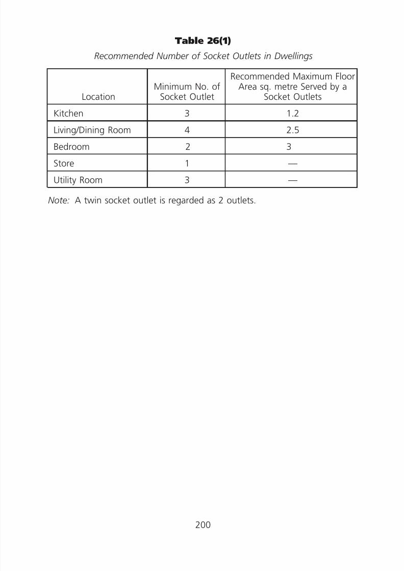
8/23/2019 Electricity Wiring
http://slidepdf.com/reader/full/electricity-wiring 200/337
2.
Table 26(1)
Recommended Number of Socket Outlets in Dwellings
LocationMinimum No. of
Socket Outlet
Recommended Maximum FloorArea sq. metre Served by a
Socket Outlets
Kitchen 3 1.2
Living/Dining Room 4 2.5
Bedroom 2 3
Store 1 —
Utility Room 3 —
Note: A twin socket outlet is regarded as 2 outlets.
200
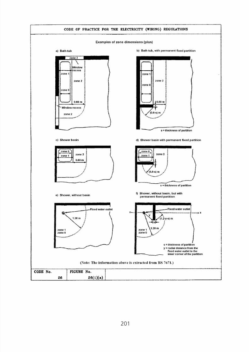
8/23/2019 Electricity Wiring
http://slidepdf.com/reader/full/electricity-wiring 201/337
201

8/23/2019 Electricity Wiring
http://slidepdf.com/reader/full/electricity-wiring 202/337
202

8/23/2019 Electricity Wiring
http://slidepdf.com/reader/full/electricity-wiring 203/337
203
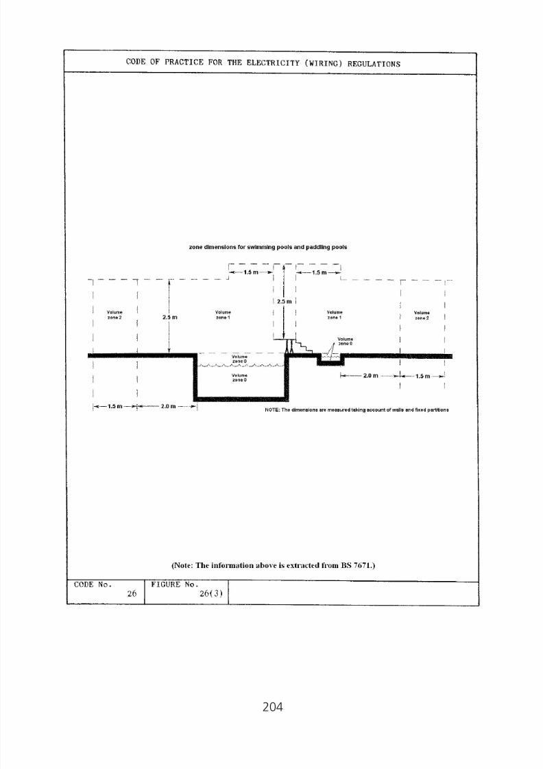
8/23/2019 Electricity Wiring
http://slidepdf.com/reader/full/electricity-wiring 204/337
204

8/23/2019 Electricity Wiring
http://slidepdf.com/reader/full/electricity-wiring 205/337
205

8/23/2019 Electricity Wiring
http://slidepdf.com/reader/full/electricity-wiring 206/337
206
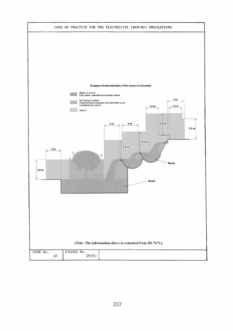
8/23/2019 Electricity Wiring
http://slidepdf.com/reader/full/electricity-wiring 207/337
207

8/23/2019 Electricity Wiring
http://slidepdf.com/reader/full/electricity-wiring 208/337
APPENDICES
1. Prescribed Requirements for 3-pin (non-reversible) 5 ampere and 15ampere Socket Outlets
2. Prescribed Requirements for 3-pin (non-reversible) 13 ampere SocketOutlets
3. Prescribed Requirements for Protected Type Non-reversible 5 ampere, 15ampere and 30 ampere Socket Outlets
4. Prescribed Requirements for Industrial Type 16 ampere, 32 ampere, 63ampere and 125 ampere Socket Outlets with Retaining Devices
5. Correction Factors for Sizing of Cable Conductors
6. Current Carrying Capacities and Voltage Drop Tables for PVC Insulatedand XLPE Insulated Cables
7. Typical Methods of Installation of Cables
8. Graphical Symbols for Electrical Diagrams
9. Performance Monitoring Points System for Registered Electrical Workers / Contractors
10. Degree of Protection Provided by Enclosures (IP Code)
11. Forms of Internal Separations for Switchgear Assemblies12. Worked Examples for Application of the CoP
13. Sample of Schedule of Test Results for Electrical Wiring and Checklists
14. References
15. Safety for Live Work
16. Sample of Permit-To-Work
17. Sample of H.V. Enclosure Log Book18. New Cable Colour Code for Fixed Electrical Installations - Installation
Guidelines
208
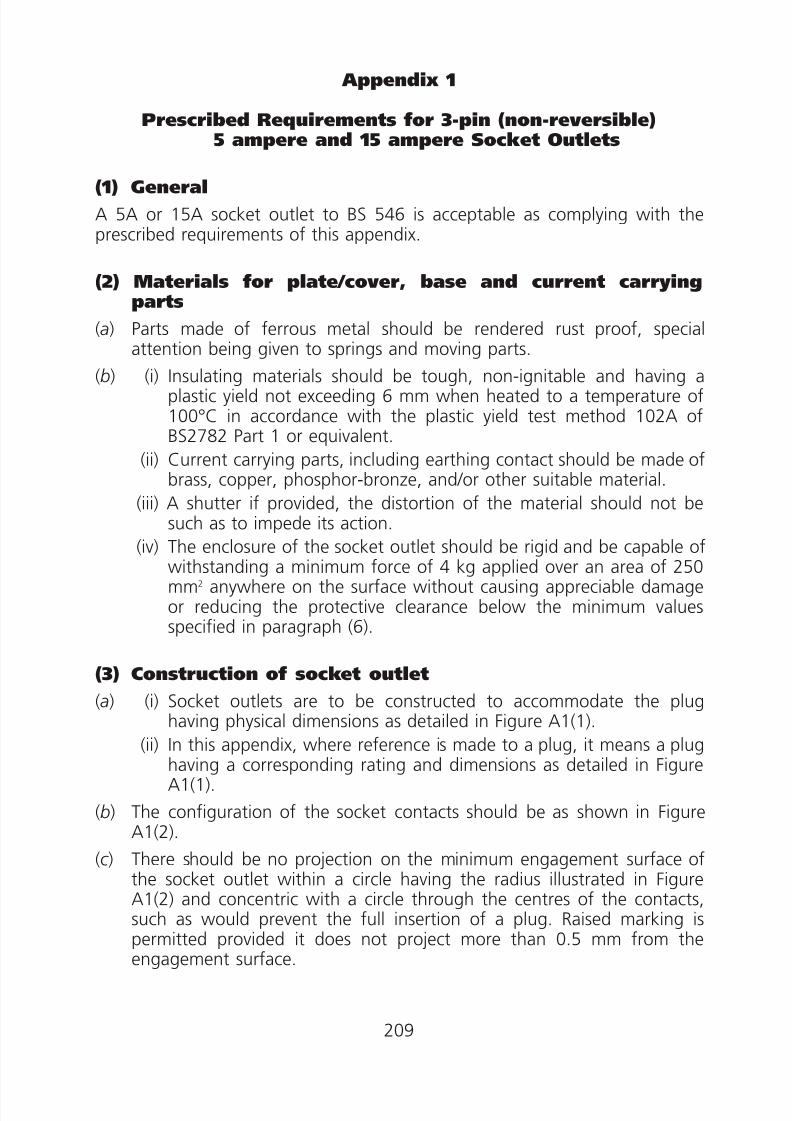
8/23/2019 Electricity Wiring
http://slidepdf.com/reader/full/electricity-wiring 209/337
Appendix 1
Prescribed Requirements for 3-pin (non-reversible)5 ampere and 15 ampere Socket Outlets
(1) General
A 5A or 15A socket outlet to BS 546 is acceptable as complying with theprescribed requirements of this appendix.
(2) Materials for plate/cover, base and current carryingparts
(a) Parts made of ferrous metal should be rendered rust proof, specialattention being given to springs and moving parts.
(b) (i) Insulating materials should be tough, non-ignitable and having aplastic yield not exceeding 6 mm when heated to a temperature of100°C in accordance with the plastic yield test method 102A ofBS2782 Part 1 or equivalent.
(ii) Current carrying parts, including earthing contact should be made ofbrass, copper, phosphor-bronze, and/or other suitable material.
(iii) A shutter if provided, the distortion of the material should not besuch as to impede its action.
(iv) The enclosure of the socket outlet should be rigid and be capable ofwithstanding a minimum force of 4 kg applied over an area of 250mm2 anywhere on the surface without causing appreciable damageor reducing the protective clearance below the minimum valuesspecified in paragraph (6).
(3) Construction of socket outlet
(a) (i) Socket outlets are to be constructed to accommodate the plug
having physical dimensions as detailed in Figure A1(1).(ii) In this appendix, where reference is made to a plug, it means a plughaving a corresponding rating and dimensions as detailed in FigureA1(1).
(b) The configuration of the socket contacts should be as shown in FigureA1(2).
(c ) There should be no projection on the minimum engagement surface ofthe socket outlet within a circle having the radius illustrated in FigureA1(2) and concentric with a circle through the centres of the contacts,such as would prevent the full insertion of a plug. Raised marking ispermitted provided it does not project more than 0.5 mm from theengagement surface.
209

8/23/2019 Electricity Wiring
http://slidepdf.com/reader/full/electricity-wiring 210/337
(d ) The spacing of the socket contacts should correspond with that of theplug pins as shown in Figure A1(1).
(e) On insertion of pins into contacts, the travel from the first point ofcontact to the complete engagement, should not be less than theminimum, or more than the maximum, given in Table A1(1).
Table A1(1) Contact Travel
Current Rating Minimum Maximum(ampere) (mm) (mm)
5 4.17 6.25
15 4.75 6.83
(f ) Socket contacts should be self-adjusting as to contact making and eachsocket contact should be such as to make and maintain, in normal use,effective electrical and mechanical contact with the corresponding plugpins. The means for producing the contact pressure should be associatedwith each socket contact independently such that individual line orneutral socket contact should be capable of retaining the withdrawal—pull of a gauge as detailed in Figure A1(3) for 30 sec. when the socket
outlet is held horizontally with the gauge hanging vertically downwards.It should be checked that neither shutter nor the cover/moulding has anyeffect on the results.
( g) Where a shutter is provided, the construction of the socket outlet shouldbe such that when a plug is withdrawn from it, the current carryingsocket contacts are automatically screened by the shutter. The shuttershould be operated by the insertion of the earthing pin.
(h) (i) Unless a shutter is provided, diameter of holes in the socket outletplate or cover for the reception of the line and the neutral plug pinsshould not exceed 5.8 mm or 7.7 mm for 5A or 15A socket outletrespectively.
(ii) The holes for the line and the neutral plug pins in metal platesshould have insulated material of at least 2 mm thick around them.
(i ) The socket outlet should be constructed to prevent a current carrying pinof a plug from making contact with a current carrying contact of the
socket while either or both of other pins are completely exposed. Theprovision of a shutter, or no part of hole intended for the reception ofline or neutral pin should be less than 16.5 mm or 21 mm from the edgeof a 5A or 15A socket outlet respectively, is acceptable for this purpose.
210

8/23/2019 Electricity Wiring
http://slidepdf.com/reader/full/electricity-wiring 211/337
( j ) Multiple socket outlets should be capable of simultaneous use of allsocket outlets.
(k ) Where a switch is incorporated:
(i) the actuating member of a switch should not remain at rest in the
off position whilst the switch contacts remain closed; and(ii) the actuating mechanism should be so constructed that whenoperated the switch can remain only in a position giving adequatecontact or adequate separation of the contacts; and
(iii) switches should be so constructed that undue arcing cannot occurwhen the switch is operated slowly; and
(iv) the switch in any switched socket outlet should disconnect thesupply to the line socket contact.
(l ) Conductive component parts of the socket outlet should be so locatedand separated that, in normal use, they cannot be displaced so as toaffect adversely the safety or proper operation of the socket outlet.
(m) (i) For the flush socket outlet intended to be used in enclosure, the sizeof the base shall be such that the clearance for the purpose of wiringbetween the base and the inside walls of the box or enclosure is notless than 6 mm.
(ii) There should be no live metal protruding from or flush with thesocket outlet base. Any exposed live metal part should be recessed
at least 2.5 mm from the base surface.(iii) Where it is intended that the fixed wiring conductors pass through
holes in the base of the socket outlet to the terminals, the minimumdiameter of each hole should not be less than 7.9 mm or 9.5 mm forthe 5A or 15A socket outlet respectively.
(4) Construction of terminals
(a) Terminals in the 5A socket outlet should permit the connection, without
special preparation, of one or two 1.5 mm2 solid or stranded conductors.
(b) Line and neutral terminals in the 15A socket outlet should permit theconnection, without special preparation, of one or two 2.5 mm2 solid orstranded conductors.
(c ) Earthing terminals should permit the connection without specialpreparation of one or two 1.5 mm2 or 2.5 mm2 solid or strandedconductors.
(d ) Where pillar terminals are used they should have clamping screws ofsufficient length to extend to the far side of the conductor hole. The endof the screw should be slightly rounded so as to minimize damage to theconductors. The sizes of the conductor hole and the clamping screwshould be such that the clearance between the sides of the major
211

8/23/2019 Electricity Wiring
http://slidepdf.com/reader/full/electricity-wiring 212/337
diameter of the clamping screw and the conductor hole does not exceed0.6 mm. The size of conductor hole should not be less than 3.5 mm or4.3 mm for 5A or 15A socket outlet respectively.
(e) Terminal screws should have a nominal diameter of not less than 2.8 mmor 3 mm for 5A or 15A socket outlets.
(5) Screws and connections
(a) Screwed connections, electrical and otherwise should withstand themechanical stresses occurring in normal use. Screws transmittingelectrical contact pressure should screw into metal.
(b) Screws should not be of insulating material if their replacement by ametal screw would affect the safety or performance requirements of theaccessory.
(c ) Where current carrying parts are screwed together, the current pathshould not rely on the screw threads.
(6) Creepage distances, clearances and distances throughinsulation
(a) When the socket outlet is correctly assembled and wired with theappropriate cable, the minimum clearance through air and the minimumcreepage distance shall be 2.5 mm:
(i) between live parts of opposite polarity;
(ii) between live parts and any other metal parts; and
(iii) between live parts and the accessible external surface of theaccessory.
(b) The minimum clearance between switch contacts in the open position forsocket outlet should be 1.2 mm.
(c ) The socket outlet should have a minimum distance of 2 mm betweeninsulated live parts and the accessible external surface.
(7) Provision of earthing
(a) The socket outlet should be so constructed that, when inserting the plug,the earth connection is made before the current carrying pins of the plugbecome live. When withdrawing the plug, the current carrying partsshould separate before the earth contact is broken.
(b) All accessible metal parts of accessories should be in effective electricalcontact with the earthing socket contact except the metal parts on, orscrews in or through, non-conducting material, and separated by such
material from current carrying parts in such a way that in normal use theycannot become live, need not be in effective electrical contact with theearthing socket contact.
212

8/23/2019 Electricity Wiring
http://slidepdf.com/reader/full/electricity-wiring 213/337
(8) Marking
(a) The socket outlet should be legibly and durably marked with thefollowing information, which should not be placed on screws, removablewashers or other easily removable parts, or upon parts intended forseparate sale:
(i) rated current;
(ii) rated voltage;
(iii) nature of supply.
(b) If symbols are used they should be as follows:
amperes A
volts V
alternating current a.c.
earth or E(c ) The letters L and N should be used to indicate the terminals
corresponding respectively to the line socket contact (L) and the neutralsocket contact (N) and letter E or symbol for the earthing socketcontact (E). The letters and symbols should be as close as practicable tothe corresponding terminals.
(9) Temperature rise
(a) The permitted temperature rise of the accessible external surface of thesocket outlet after the test of subparagraph (b) should be 50°C.
(b) The following procedures of the test on the temperature rise of theaccessible external surface of the socket outlet are acceptable:
(i) Temperature rise of socket outlets should be measured by fine wirethermocouples.
(ii) Surface mounted outlets should be mounted as in use with theiraccompanying mounting block or backplate fixed to a vertical
plywood board 25 mm thick and having a flat surface extending atleast 150 mm in each direction beyond the extremity of the socketoutlet.
(iii) Flush mounted socket outlets should be mounted on socket outletboxes with an internal depth of 35 mm. The flush mounted socketoutlet box is placed in a block of wood, so that the front edges ofthe box are between 2.5 mm and 5 mm below the front surface ofthe block. The size of the block should be such that there is aminimum of 25 mm of wood surrounding the box on all four sides
and the back.(iv) Socket outlets under test should be subjected to its rated loadingconnected via a plug for a minimum continuous period of 4 hours orlonger until stability is reached with a maximum duration of 8 hours,stability being taken as less than 1°C rise within 1 hour.
213

8/23/2019 Electricity Wiring
http://slidepdf.com/reader/full/electricity-wiring 214/337
214

8/23/2019 Electricity Wiring
http://slidepdf.com/reader/full/electricity-wiring 215/337
215

8/23/2019 Electricity Wiring
http://slidepdf.com/reader/full/electricity-wiring 216/337
216

8/23/2019 Electricity Wiring
http://slidepdf.com/reader/full/electricity-wiring 217/337
Appendix 2
Prescribed Requirements for 3-pin (non-reversible) 13 ampere Socket Outlets
(1) GeneralA 13A outlet to BS 1363 is acceptable subject to complying with theprescribed requirements of this appendix.
(2) Materials for plate/cover, base and current carryingparts
(a) Parts made of ferrous metal should be rendered rust proof, specialattention being given to springs and moving parts.
(b) (i) Insulating materials should be tough, non-ignitable and not softenwhen heated to a temperature of 100°C
(ii) Current carrying parts, including earthing contact should be made ofbrass, copper, phosphor-bronze, and/or other suitable material.
(iii) The material of the shutter should not distort to an extent to impedeits action.
(iv) The enclosure of the socket outlet should be rigid and be capable ofwithstanding a minimum force of 4 kg applied over an area of 250
mm2
anywhere on the surface without causing appreciable damageor reducing the protective clearance below the minimum valuesspecified in paragraph (6).
(3) Construction of socket outlet
(a) (i) Socket outlets are to be constructed to accommodate the plughaving physical dimensions as detailed in Figure A2(1).
(ii) In this appendix, where reference is made to a plug, it means a plughaving a current rating and dimensions of 13A as detailed in Figure
A2(1).
(b) The configuration of the socket contacts should be as shown in FigureA2(2).
(c ) There should be no projection on the minimum engagement surface ofthe socket outlet illustrated in Figure A2(2), such as would prevent thefull insertion of a plug. Raised marking is permitted provided it does notproject more than 0.5 mm from the engagement surface.
(d ) The spacing of the socket contacts should correspond with that of theplug pins as shown in Figure A2(1).
(e) On insertion of pins into contacts, the travel of the end of either currentcarrying pin from the first face of the socket outlet to the first point of
217
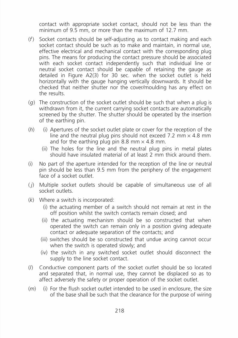
8/23/2019 Electricity Wiring
http://slidepdf.com/reader/full/electricity-wiring 218/337
contact with appropriate socket contact, should not be less than theminimum of 9.5 mm, or more than the maximum of 12.7 mm.
(f ) Socket contacts should be self-adjusting as to contact making and eachsocket contact should be such as to make and maintain, in normal use,effective electrical and mechanical contact with the corresponding plugpins. The means for producing the contact pressure should be associatedwith each socket contact independently such that individual line orneutral socket contact should be capable of retaining the gauge asdetailed in Figure A2(3) for 30 sec. when the socket outlet is heldhorizontally with the gauge hanging vertically downwards. It should bechecked that neither shutter nor the cover/moulding has any effect onthe results.
( g) The construction of the socket outlet should be such that when a plug is
withdrawn from it, the current carrying socket contacts are automaticallyscreened by the shutter. The shutter should be operated by the insertionof the earthing pin.
(h) (i) Apertures of the socket outlet plate or cover for the reception of theline and the neutral plug pins should not exceed 7.2 mm × 4.8 mmand for the earthing plug pin 8.8 mm × 4.8 mm.
(ii) The holes for the line and the neutral plug pins in metal platesshould have insulated material of at least 2 mm thick around them.
(i) No part of the aperture intended for the reception of the line or neutralpin should be less than 9.5 mm from the periphery of the engagementface of a socket outlet.
( j ) Multiple socket outlets should be capable of simultaneous use of allsocket outlets.
(k ) Where a switch is incorporated:
(i) the actuating member of a switch should not remain at rest in theoff position whilst the switch contacts remain closed; and
(ii) the actuating mechanism should be so constructed that whenoperated the switch can remain only in a position giving adequatecontact or adequate separation of the contacts; and
(iii) switches should be so constructed that undue arcing cannot occurwhen the switch is operated slowly; and
(iv) the switch in any switched socket outlet should disconnect thesupply to the line socket contact.
(l ) Conductive component parts of the socket outlet should be so located
and separated that, in normal use, they cannot be displaced so as toaffect adversely the safety or proper operation of the socket outlet.
(m) (i) For the flush socket outlet intended to be used in enclosure, the sizeof the base shall be such that the clearance for the purpose of wiring
218
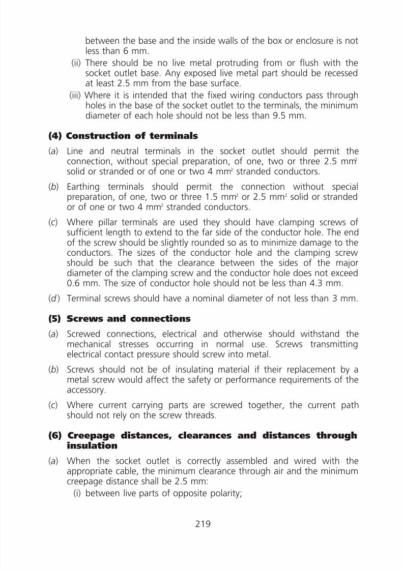
8/23/2019 Electricity Wiring
http://slidepdf.com/reader/full/electricity-wiring 219/337
between the base and the inside walls of the box or enclosure is notless than 6 mm.
(ii) There should be no live metal protruding from or flush with thesocket outlet base. Any exposed live metal part should be recessedat least 2.5 mm from the base surface.
(iii) Where it is intended that the fixed wiring conductors pass throughholes in the base of the socket outlet to the terminals, the minimumdiameter of each hole should not be less than 9.5 mm.
(4) Construction of terminals
(a) Line and neutral terminals in the socket outlet should permit theconnection, without special preparation, of one, two or three 2.5 mm2
solid or stranded or of one or two 4 mm2 stranded conductors.
(b) Earthing terminals should permit the connection without specialpreparation, of one, two or three 1.5 mm2 or 2.5 mm2 solid or strandedor of one or two 4 mm2 stranded conductors.
(c ) Where pillar terminals are used they should have clamping screws ofsufficient length to extend to the far side of the conductor hole. The endof the screw should be slightly rounded so as to minimize damage to theconductors. The sizes of the conductor hole and the clamping screwshould be such that the clearance between the sides of the major
diameter of the clamping screw and the conductor hole does not exceed0.6 mm. The size of conductor hole should not be less than 4.3 mm.
(d ) Terminal screws should have a nominal diameter of not less than 3 mm.
(5) Screws and connections
(a) Screwed connections, electrical and otherwise should withstand themechanical stresses occurring in normal use. Screws transmittingelectrical contact pressure should screw into metal.
(b) Screws should not be of insulating material if their replacement by ametal screw would affect the safety or performance requirements of theaccessory.
(c ) Where current carrying parts are screwed together, the current pathshould not rely on the screw threads.
(6) Creepage distances, clearances and distances throughinsulation
(a) When the socket outlet is correctly assembled and wired with theappropriate cable, the minimum clearance through air and the minimumcreepage distance shall be 2.5 mm:
(i) between live parts of opposite polarity;
219

8/23/2019 Electricity Wiring
http://slidepdf.com/reader/full/electricity-wiring 220/337
(ii) between live parts and any other metal parts; and
(iii) between live parts and the accessible external surface of theaccessory.
(b) The minimum clearance between switch contacts in the open position for
socket outlet should be 1.2 mm.(c ) The socket outlet should have a minimum distance of 2 mm between
insulated live parts and the accessible external surface.
(7) Accessibility of live parts
Socket outlets should be so designed that when mounted and wired as innormal use, live parts are not accessible as tested by a test pin shown in FigureA2(4).
(8) Provision of earthing
(a) The socket outlet should be so constructed that, when inserting the plug,the earth connection is made before the current carrying pins of the plugbecome live. When withdrawing the plug, the current carrying partsshould separate before the earth contact is broken.
(b) All accessible metal parts of accessories should be in effective electricalcontact with the earthing socket contact except the metal parts on, orscrews in or through, non-conducting material, and separated by suchmaterial from current carrying parts in such a way that in normal use theycannot become live, need not be in effective electrical contact with theearthing socket contact.
(9) Marking
(a) The socket outlet should be legibly and durably marked with thefollowing information, which should not be placed on screws, removablewashers or other easily removable parts, or upon parts intended for
separate sale:(i) rated current;
(ii) rated voltage;
(iii) nature of supply.
(b) If symbols are used they should be as follows—
amperes A
volts V
alternating current a.c.
earth or E
220
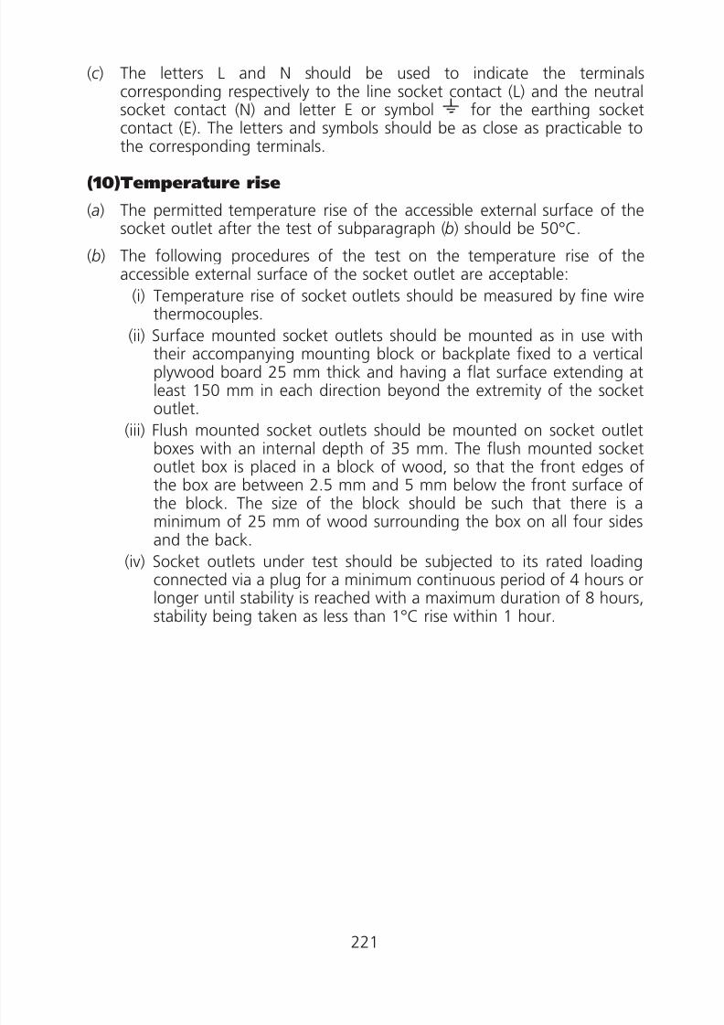
8/23/2019 Electricity Wiring
http://slidepdf.com/reader/full/electricity-wiring 221/337
(c ) The letters L and N should be used to indicate the terminalscorresponding respectively to the line socket contact (L) and the neutralsocket contact (N) and letter E or symbol for the earthing socketcontact (E). The letters and symbols should be as close as practicable tothe corresponding terminals.
(10)Temperature rise
(a) The permitted temperature rise of the accessible external surface of thesocket outlet after the test of subparagraph (b) should be 50°C.
(b) The following procedures of the test on the temperature rise of theaccessible external surface of the socket outlet are acceptable:
(i) Temperature rise of socket outlets should be measured by fine wirethermocouples.
(ii) Surface mounted socket outlets should be mounted as in use withtheir accompanying mounting block or backplate fixed to a verticalplywood board 25 mm thick and having a flat surface extending atleast 150 mm in each direction beyond the extremity of the socketoutlet.
(iii) Flush mounted socket outlets should be mounted on socket outletboxes with an internal depth of 35 mm. The flush mounted socketoutlet box is placed in a block of wood, so that the front edges ofthe box are between 2.5 mm and 5 mm below the front surface of
the block. The size of the block should be such that there is aminimum of 25 mm of wood surrounding the box on all four sidesand the back.
(iv) Socket outlets under test should be subjected to its rated loadingconnected via a plug for a minimum continuous period of 4 hours orlonger until stability is reached with a maximum duration of 8 hours,stability being taken as less than 1°C rise within 1 hour.
221

8/23/2019 Electricity Wiring
http://slidepdf.com/reader/full/electricity-wiring 222/337
222

8/23/2019 Electricity Wiring
http://slidepdf.com/reader/full/electricity-wiring 223/337
223

8/23/2019 Electricity Wiring
http://slidepdf.com/reader/full/electricity-wiring 224/337
224

8/23/2019 Electricity Wiring
http://slidepdf.com/reader/full/electricity-wiring 225/337
225

8/23/2019 Electricity Wiring
http://slidepdf.com/reader/full/electricity-wiring 226/337
Appendix 3
Prescribed Requirements for Protected TypeNon-reversible 5 ampere, 15 ampere and
30 ampere Socket Outlets
(1) General
A 5A or 15A or 30A socket outlet to BS 196 is acceptable as complying withthe prescribed requirements of this appendix.
(2) Materials for plate/cover, base and current carryingparts
(a) Parts made of ferrous metal should be rendered rust proof, specialattention being given to springs and moving parts.
(b) (i) Insulating materials should be tough, non-ignitable and not softenwhen heated to a temperature of 100°C.
(ii) Current carrying parts, including earthing contact should be made ofbrass, copper, phosphor-bronze, and/or other suitable material.
(iii) The enclosure of the socket outlet should be rigid and be capable ofwithstanding a minimum force of 4 kg applied over an area of 250mm2 anywhere on the surface without causing appreciable damage
or reducing the protective clearance below the minimum valuesspecified in paragraph (6).
(3) Construction of socket outlet
(a) (i) The socket outlet is to be constructed to accommodate the plughaving physical dimensions as detailed in Figure A3(1).
(ii) In this appendix, where reference is made to a plug, it means a plughaving a corresponding rating and dimensions as detailed in Figure
A3(1).
(b) The configuration of the socket contacts should be as shown in FigureA3(2).
(c ) The essential dimensions of the socket outlet fed exclusively by a radialfinal circuit is shown in Figure A3(2).
(d ) Socket contacts should be self-adjusting as to contact making and eachsocket contact should such as to make and maintain, in normal use,
effective electrical and mechanical contact with the corresponding plugpins. The means for producing the contact pressure should be associatedwith each socket contact independently.
226

8/23/2019 Electricity Wiring
http://slidepdf.com/reader/full/electricity-wiring 227/337
(e) Conductive component parts of socket outlets should be so located andseparated that, in normal use, they cannot be displaced so as to affectadversely the safety or proper operation of the socket outlet.
(f ) Where the socket outlet is required to be weatherproof, it should betotally enclosed when fitted with screwed conduits, or PVC sheathedcables and without a plug in position. The socket outlets should bethreaded with dimensions given in Figure A3(3) for use with thecorresponding screwed ring fitted to plugs.
( g) For a ring or radial final circuit feeding a number of socket outlets andwhere:
(i) the circuit has one pole earthed, the socket outlet should be of thetype that will accept only 2-pole-and-earth contact plugs with single-pole fusing on the live pole. Such socket outlets with raised socket
keys are shown in Figure A3(4), and those with socket keywaysrecessed at position ‘B’ are shown in Figure A3(5).
(ii) the circuit has neither pole earthed (e.g. a circuit supplied from adouble-wound transformer having the midpoint of its secondarywinding earthed), the socket outlet should be of the type that willaccept only 2-pole-and-earth contact plugs with double-pole fusing.Such socket outlet is those which have raised socket keys as shownin Figure A3(4), together with socket keyways recessed at position‘P’ as shown in figure A3(5).
(4) Construction of terminals
(a) Connection should be made by means of screws, nuts or equally effectivedevices.
(b) When pillar type terminals are used, they should comply with thefollowing requirements:
(i) the minimum dimensions are in accordance with Figure A3(2).
(ii) the cable clamping screws should be long enough to reach theopposite surface of the cable hole, and should have rounded ends,and
(iii) the surface of the cable hole against which the cable is clampedshould be smooth and unbroken.
(c ) Terminals should be effectively enclosed. Insulating barriers securely fixedto, or forming an integral part of the interiors, should be provided toseparate internal metal at different potential including any bare flexibleconductors, even if such conductors should become detached from theirterminals.
227

8/23/2019 Electricity Wiring
http://slidepdf.com/reader/full/electricity-wiring 228/337
(d ) An earthing terminal should be provided and be so arranged that theearth wire of the cable, if any, is visible at least when the plug orappliance inlet is removed from the corresponding socket outlet orconnector.
(5) Screws and connections(a) Screwed connections, electrical and otherwise should withstand the
mechanical stresses occurring in normal use. Screws transmittingelectrical contact pressure should screw into metal.
(b) Screws should not be made of insulating material if their replacement bya metal screw would affect the safety or performance requirements ofthe accessory.
(c ) Where current carrying parts are screwed together, the current path
should not rely on the screw threads.
(6) Creepage distances, clearances and distances throughinsulation
(a) When the socket outlet is correctly assembled and wired with theappropriate cable, the minimum clearance through air and the minimumcreepage distance shall be 2.5 mm:
(i) between live parts of opposite polarity;
(ii) between live parts and any other metal parts; and
(iii) between live parts and the accessible external surface of theaccessory.
(b) The socket outlet should have a minimum distance of 2 mm betweeninsulated live parts and the accessible external surface.
(7) Accessibility of live parts
Socket outlets should be so designed that when mounted and wired as innormal use, live parts are not accessible as tested by a test finger shown inFigure A3(6).
(8) Provision of earthing
(a) Socket outlets should be so constructed with scraping earthing contactthat, when inserting the plug, the earth connection is made before thecurrent carrying pins of the plug become live. When withdrawing the
plug, the current carrying parts should separate before the earth contactis broken.
228

8/23/2019 Electricity Wiring
http://slidepdf.com/reader/full/electricity-wiring 229/337
(b) All accessible metal parts at accessories shall be in effective electricalcontact with the scraping earthing contact except that metal parts on, orscrews in or through, non-conducting material, and separated by suchmaterial from current carrying parts in such a way that in normal use theycannot become live, need not be in effective electrical contact with the
scraping earthing contact.
(9) Marking
(a) The socket outlet should be legibly and durably marked with thefollowing information, which should not be placed on screws, removablewashers or other easily removable parts, or upon parts intended forseparate sale:
(i) rated current;
(ii) rated voltage;(iii) nature of supply.
(b) If symbols are used they should be as follows:
amperes A
volts V
alternating current a.c.
earth or E(c ) The letters L and N should be used to indicate the terminals
corresponding respectively to the line socket contact (L) and the neutralsocket contact (N) and letter E or symbol for the earthing socketcontact (E). The letters and symbols should be as close as practicable tothe corresponding terminals.
(10)Temperature rise
(a) The permitted temperature rise of the accessible external surface of thesocket outlet after the test of subparagraph (b) should be 50°C.
(b) The following procedures of the test on the temperature rise of theaccessible external surface of the socket outlet are acceptable:
(i) Temperature rise of socket outlets should be measured by fine wirethermocouples.
(ii) Socket outlets under test should be subjected to its rated loadingconnected via a plug for a minimum continuous period of 1 hour.
(iii) Sockets and plugs should be mounted and connected as in normaluse.
229

8/23/2019 Electricity Wiring
http://slidepdf.com/reader/full/electricity-wiring 230/337
230
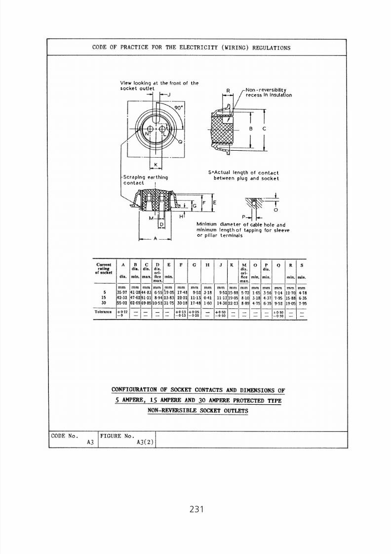
8/23/2019 Electricity Wiring
http://slidepdf.com/reader/full/electricity-wiring 231/337
231

8/23/2019 Electricity Wiring
http://slidepdf.com/reader/full/electricity-wiring 232/337
232

8/23/2019 Electricity Wiring
http://slidepdf.com/reader/full/electricity-wiring 233/337
233

8/23/2019 Electricity Wiring
http://slidepdf.com/reader/full/electricity-wiring 234/337
234

8/23/2019 Electricity Wiring
http://slidepdf.com/reader/full/electricity-wiring 235/337
235

8/23/2019 Electricity Wiring
http://slidepdf.com/reader/full/electricity-wiring 236/337
Appendix 4
Prescribed Requirements for Industrial Type 16 ampere,32 ampere, 63 ampere and 125 ampere Socket Outlets
with Retaining Devices
(1) General
A 16A or 32A or 63A or 125A socket outlet to IEC 60309 is acceptable ascomplying with the prescribed requirements of this appendix.
(2) Materials for plate/cover, base and current carryingparts
(a) Parts made of ferrous metal should be rendered rust proof, special
attention being given to springs and moving parts.(b) (i) Insulating materials should be tough, non-ignitable and not soften
when heated to a temperature of 100°C.
(ii) Current carrying parts, including earthing contact should be made ofbrass, copper, phosphor-bronze, and/or other suitable material.
(iii) The enclosure of the socket outlet should be rigid and be capable ofwithstanding a minimum force of 4 kg applied over an area of 250mm2 anywhere on the surface without causing appreciable damageor reducing the protective clearance below the minimum valuesspecified in paragraph (6).
(3) Construction of socket outlet
(a) (i) The socket outlet is to be constructed to accommodate the plughaving physical dimensions as detailed in Figure A4(1) and A4(2).
(ii) In this appendix, where reference is made to a plug, it means a plughaving a corresponding rating and dimensions as detailed in FigureA4(1) and A4(2).
(b) The configuration of the socket contacts should be as shown in FigureA4(3) and A4(4).
(c ) The essential dimensions of the socket outlets are shown in Figure A4(3)and A4(4).
(d ) Socket contacts should be self-adjusting as to contact making and eachsocket contact should such as to make and maintain, in normal use,effective electrical and mechanical contact with the corresponding plugpins. The means for producing the contact pressure should be associatedwith each socket contact independently.
(e) Conductive component parts of the socket outlet should be so locatedand separated that, in normal use, they cannot be displaced so as toaffect adversely the safety or proper operation of the socket outlet.
236

8/23/2019 Electricity Wiring
http://slidepdf.com/reader/full/electricity-wiring 237/337
(f ) (i) Socket outlets having a rated current exceeding 32A should besplash proof or watertight.
(ii) Sockets outlets having a rated current exceeding 63A should bewatertight.
( g) Splash proof socket outlets should be totally enclosed when fitted withscrewed conduits, or lead sheathed or armoured cables and without aplug in position.
(h) The construction of splash proof or watertight socket outlets to FigureA4(5) or Figure A4(6) are acceptable.
(i) 63A and 125A socket outlets should have provision for an electricalinterlock in the form of a pilot contact shown on Figure A4(4).
( j ) Socket outlets should be provided with a retaining device as indicated inTable A4(1).
Table A4(1)—Retaining devices
Rated Current ofthe Socket Outlet
Amperes
ClassificationAccording to
Degree ofProtection
against Moisture Retaining MeansFigures
Referred to
ordinary lever or lid A4(7)16 and 32 splash proof lid A4(7)
watertight two-ramp system A4(8)
63
splash proof lid and two-ramp
system
A4(5)
watertight two-ramp system A4(6)
125 watertight two-ramp system A4(6)
(4) Construction of terminals
(a) Connection should be made by means of screws, nuts or equally effectivedevices.
(b) Dimensions of terminals should comply with Figure A4(9) for pillarterminals, Figure A4(10) for screw terminals and stud terminals, FigureA4(11) for saddle terminals and Figure A4(12) for lug terminals.
(c ) Terminals should be effectively enclosed. Insulating barriers securely fixedto, or forming an integral part of the interiors, should be provided toseparate internal metal at different potential including any bare flexibleconductors, ever if such conductors should become detached from theirterminals.
237
8/23/2019 Electricity Wiring
http://slidepdf.com/reader/full/electricity-wiring 238/337
(5) Screws and connections
(a) Screwed connections, electrical and otherwise should withstand themechanical stresses occurring in normal use. Screws transmittingelectrical contact pressure should screw into metal.
(b) Screws should not be of insulating material if their replacement by ametal screw would affect the safety or performance requirements of theaccessory.
(c ) Where current carrying parts are screwed together, the current pathshould not rely on the screw threads.
(d ) Screws and nuts for clamping the conductors should not serve to fix anyother component.
(6) Creepage distances, clearances and distances throughinsulation
(a) When the socket outlet is correctly assembled and wired with theappropriate cable, the minimum clearance through air and the minimumcreepage distance should be 4 mm:
(i) between live parts of opposite polarity;
(ii) between live parts and any other metal parts; and
(iii) between live parts and the accessible external surface of theaccessory.
(b) The socket outlet should have a minimum distance of 2 mm betweeninsulated live parts and the accessible external surface.
(7) Accessibility of live parts
Socket outlets should be so designed that when mounted and wired as innormal use, live parts are not accessible as tested by a test finger shown inFigure A3(6).
(8) Provision for earthing(a) The socket outlet should be so constructed with earthing contacts which
should be directly connected to an internal earthing terminal.
(b) Metalclad socket outlets should be provided with an earthing terminalintended for connection of an external earthing conductor, except forflush type socket outlets, this earthing terminal should be so arrangedthat the protective conductor of the cable, if any, is visible at least whenthe plug or appliance inlet is removed from the corresponding socketoutlet.
(c ) All accessible metal parts of the socket outlet should be in effectiveelectrical contact with the earthing contact except that metal parts on, orscrews in or through, non-conducting material, and separated by such
238
8/23/2019 Electricity Wiring
http://slidepdf.com/reader/full/electricity-wiring 239/337
material from current carrying parts in such a way that in normal use theycannot become live, need not be in effective electrical contact with thescraping earthing contact.
(9) Marking
(a) The socket outlet should be legibly and durably marked with thefollowing information, which should not be placed on screws, removablewashers or other easily removable parts, or upon parts intended forseparate sale:
(i) rated current;
(ii) rated voltage;
(iii) nature of supply.
(b) If symbols are used they should be as follows:
amperes A
volts V
alternating current a.c.
earth or E
splash proof construction
watertight construction
(c ) The letters R1, S2, T3 and N should be used to indicate the terminalscorresponding respectively to the phase socket contacts and the neutralsocket contact (N), and a symbol for the earth contact. The letters andsymbols should be as close as practicable to the corresponding terminals.
(10)Temperature rise
(a) The permitted temperature rise of the accessible external surface of the
socket outlet after the test of subparagraph (b) should be 50°C.(b) The following procedures of the test on the temperature rise of the
accessible external surface of the socket outlet are acceptable:
(i) Temperature rise of socket outlets should be measured by fine wirethermocouples.
(ii) The socket outlets under test should be subjected to its rated loadingconnected via a plug. The duration of the test is 1 hour for socketoutlets having a rated current not exceeding 32A; and 2 hours forsocket outlets having a rated current exceeding 32A.
(c ) Socket outlets and plugs should be mounted and connected as in normaluse.
239

8/23/2019 Electricity Wiring
http://slidepdf.com/reader/full/electricity-wiring 240/337
240
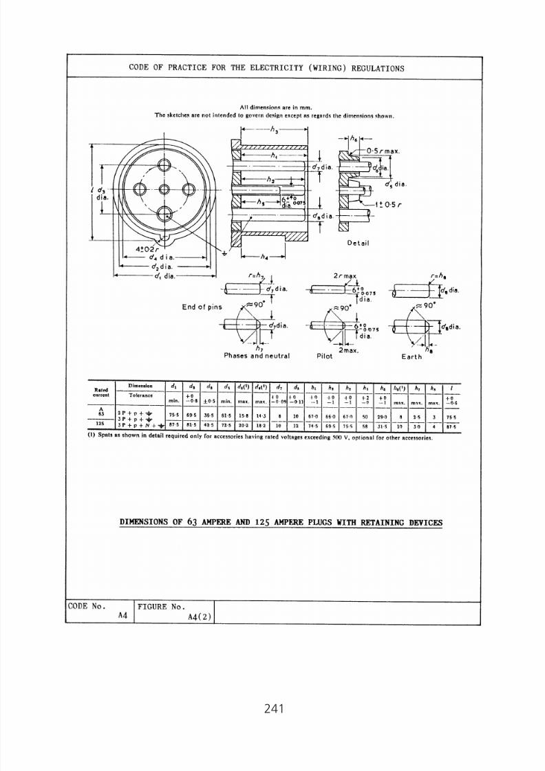
8/23/2019 Electricity Wiring
http://slidepdf.com/reader/full/electricity-wiring 241/337
241

8/23/2019 Electricity Wiring
http://slidepdf.com/reader/full/electricity-wiring 242/337
242

8/23/2019 Electricity Wiring
http://slidepdf.com/reader/full/electricity-wiring 243/337
243

8/23/2019 Electricity Wiring
http://slidepdf.com/reader/full/electricity-wiring 244/337
244

8/23/2019 Electricity Wiring
http://slidepdf.com/reader/full/electricity-wiring 245/337
245

8/23/2019 Electricity Wiring
http://slidepdf.com/reader/full/electricity-wiring 246/337
246
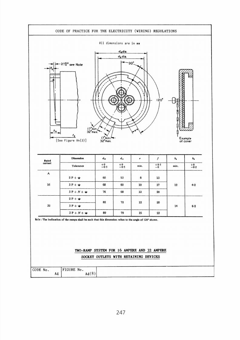
8/23/2019 Electricity Wiring
http://slidepdf.com/reader/full/electricity-wiring 247/337
247
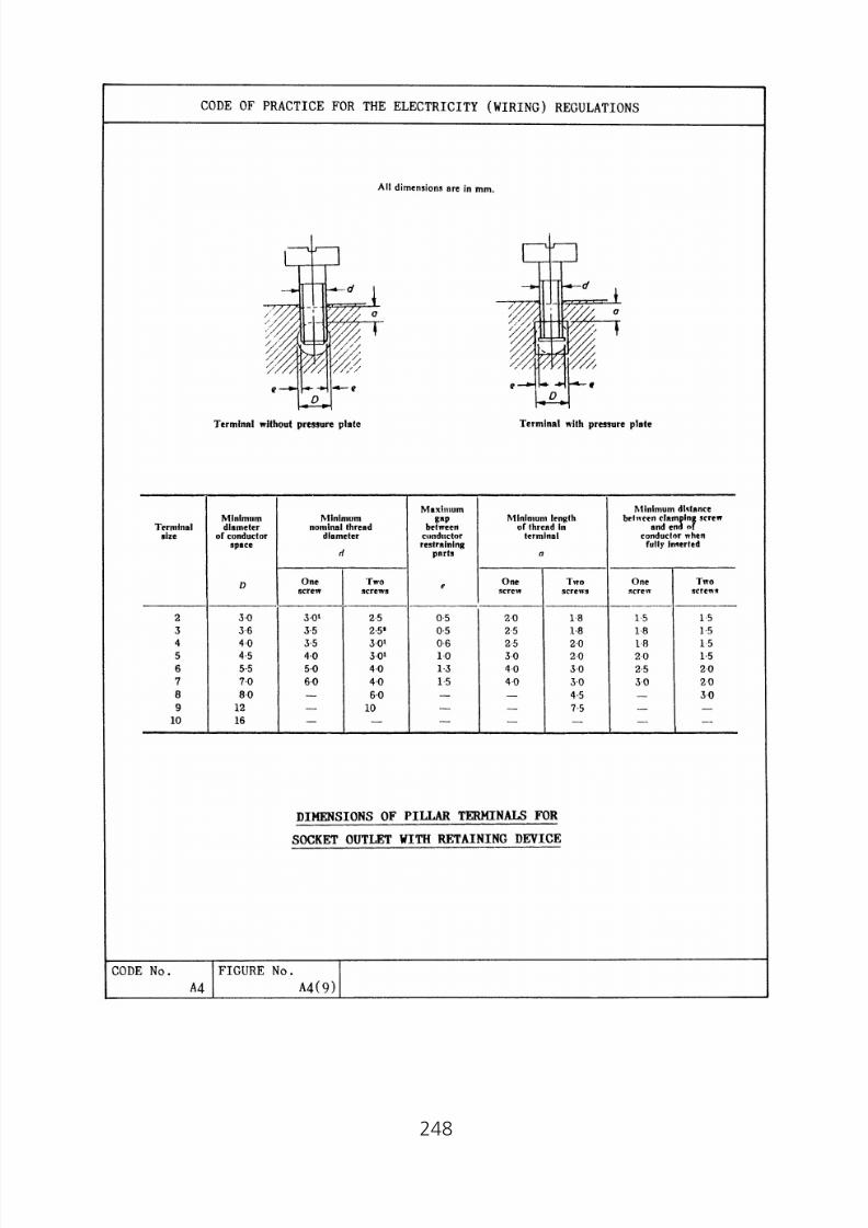
8/23/2019 Electricity Wiring
http://slidepdf.com/reader/full/electricity-wiring 248/337
248
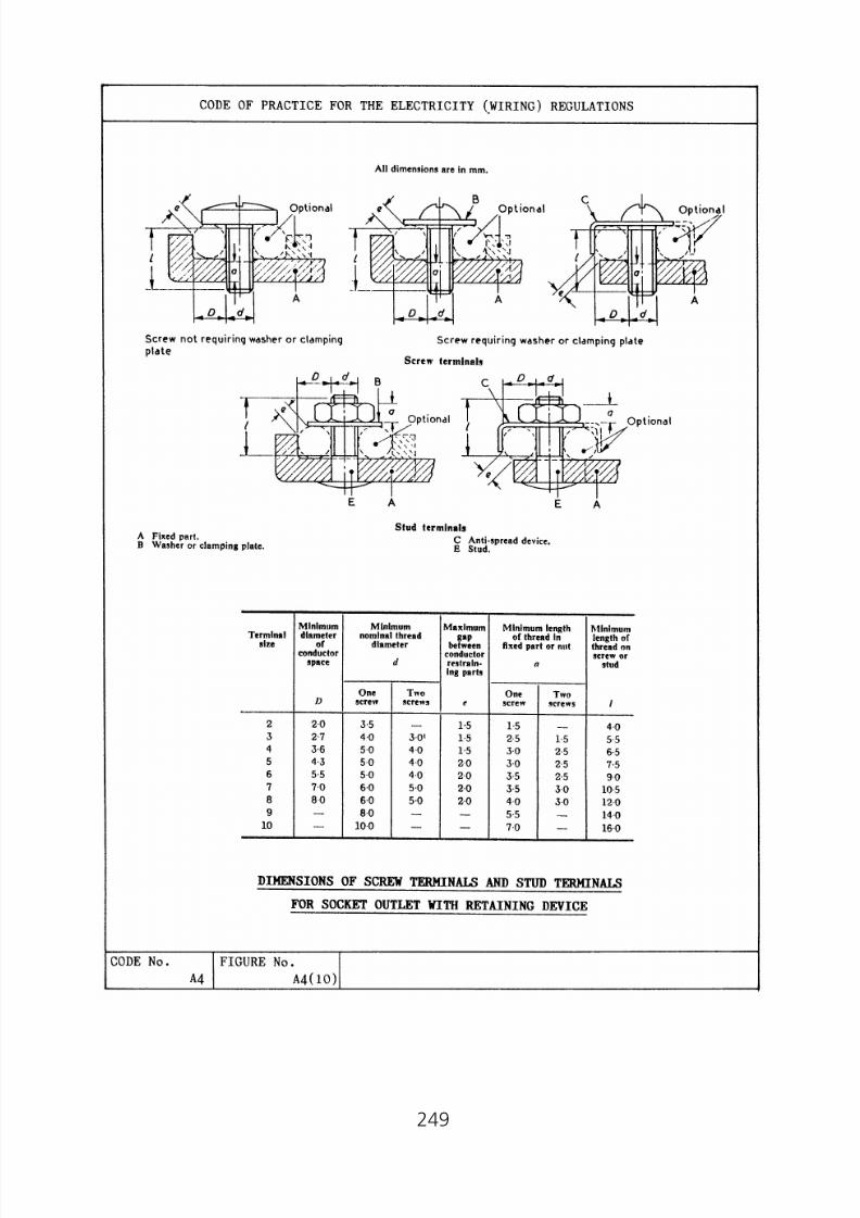
8/23/2019 Electricity Wiring
http://slidepdf.com/reader/full/electricity-wiring 249/337
249
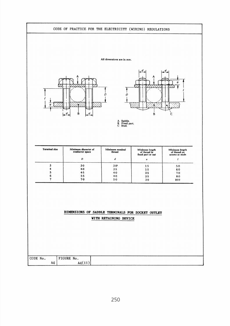
8/23/2019 Electricity Wiring
http://slidepdf.com/reader/full/electricity-wiring 250/337
250

8/23/2019 Electricity Wiring
http://slidepdf.com/reader/full/electricity-wiring 251/337
251

8/23/2019 Electricity Wiring
http://slidepdf.com/reader/full/electricity-wiring 252/337
Appendix 5
Correction Factors for Sizing of Cable Conductors
(1) Correction factors for ambient temperature
Table A5(1)
Correction factors for ambient temperature
Note: This table applies where the associated overcurrent protective device is intended toprovide short circuit protection only. Except where the device is a semi-enclosed fuse toBS3036 the table also applies where the device is intended to provide overload protection.
Note: Correction factors for flexible cords and for 85°C or 150°C rubber insulated flexible cables are given in the relevant tableof current carrying capacity in BS 7671.
* These factors are applicable only to ratings in columns 2 to 5 of Table A6(1).
Table A5(2)
Correction factors for ambient temperature where the overload protective device is a semi-enclosed fuse to BS3036
Note: Correction factors for flexible cords and for 85°C or 150°C rubber insulated flexible cables are given in the relevant table ofcurrent carrying capacity in BS 7671.
* These factors are applicable only to ratings in columns 2 to 5 of Table A6(1).
252

8/23/2019 Electricity Wiring
http://slidepdf.com/reader/full/electricity-wiring 253/337
(2) Correction factors for groups of cables
Table A5(3)
Correction factors for groups of more than one circuit of
single-core cables, or more than one multicore cable
* ‘Spaced’ means a clearance between adjacent surfaces of at least one cable diameter (De).Where the horizontal clearances between adjacent cables exceeds 2De, no correction factorneeds to be applied.
# Not applicable to Mineral Insulated Cables. Please refer to BS 7671 for the required correctionfactors.
Notes to Table A5(3)
1. The factors in the table are applicable to groups of cables of one sizeonly. The value of current derived from application of the appropriatefactors is the maximum continuous current to be carried by any of thecables in the group.
2. If, due to known operating conditions, a cable is expected to carry notmore than 30% of its grouped rating, it may be ignored for the purposeof obtaining the rating factor for the rest of the group.
3. When cables having different conductor operating temperatures aregrouped together, the current rating should be based upon the lowestoperating temperature of any cable in the group.
253
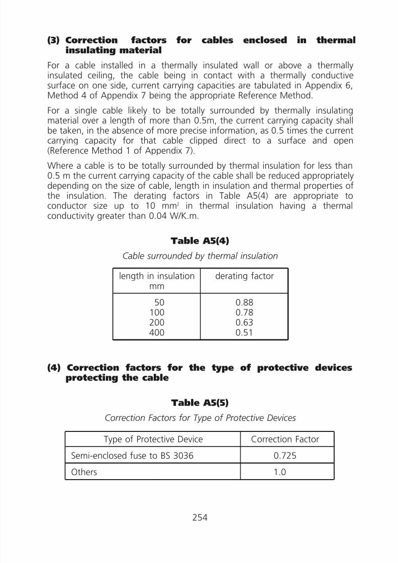
8/23/2019 Electricity Wiring
http://slidepdf.com/reader/full/electricity-wiring 254/337
0
00
(3) Correction factors for cables enclosed in thermalinsulating material
For a cable installed in a thermally insulated wall or above a thermallyinsulated ceiling, the cable being in contact with a thermally conductivesurface on one side, current carrying capacities are tabulated in Appendix 6,Method 4 of Appendix 7 being the appropriate Reference Method.
For a single cable likely to be totally surrounded by thermally insulatingmaterial over a length of more than 0.5m, the current carrying capacity shallbe taken, in the absence of more precise information, as 0.5 times the currentcarrying capacity for that cable clipped direct to a surface and open(Reference Method 1 of Appendix 7).
Where a cable is to be totally surrounded by thermal insulation for less than0.5 m the current carrying capacity of the cable shall be reduced appropriately
depending on the size of cable, length in insulation and thermal properties ofthe insulation. The derating factors in Table A5(4) are appropriate toconductor size up to 10 mm2 in thermal insulation having a thermalconductivity greater than 0.04 W/K.m.
Table A5(4)
Cable surrounded by thermal insulation
length in insulationmm
derating factor
50100200400
0.880.780.630.51
(4) Correction factors for the type of protective devicesprotecting the cable
Table A5(5)
Correction Factors for Type of Protective Devices
Type of Protective Device Correction Factor
Semi-enclosed fuse to BS 3036 0.725Others 1.0
254

8/23/2019 Electricity Wiring
http://slidepdf.com/reader/full/electricity-wiring 255/337
(5) Correction factors for cables installed in enclosedtrenches
Table A5(6)
Correction factors for cable installed in enclosed trenches(Installation Methods 18, 19 and 20 of Appendix 7)*
The correction factors tabulated below relate to the disposition of cablesillustrated in items 18 to 20 of Appendix 7 and are applicable to the currentcarrying capacities for installation methods 12 or 13 of Appendix 7 as given inthe tables of Appendix 6:
Correction Factors
* When cables having different conductor operating temperatures are grouped together thecurrent rating should be based on the lowest operating temperature of any cable in the group.
255

8/23/2019 Electricity Wiring
http://slidepdf.com/reader/full/electricity-wiring 256/337
(Note:
(Note:
Appendix 6
Current Carrying Capacities and Voltage Drop Tables forPVC Insulated and XLPE Insulated Cables
(Note: 1. For cable types other than PVC insulated or XLPE insulated cables,tables of current carrying capacities and voltage drop can beobtained in BS 7671.
2. PVC insulated cables are also known as 70°C thermoplasticinsulated cables.
3. XLPE insulated cables are also known as 90°C thermosettinginsulated cables.)
1. Tables of current carrying capacities
(a) The tabulated current carrying capacities relate to continuous loadingof cables in single circuit with the installation methods shown inAppendix 7. The values correspond to the conductor operatingtemperatures indicated in the headings of the tables and for a.c.operation apply only to frequencies in the range 49 to 61 Hz.
(b) The values of current tabulated represent current carrying capacitieswhere no correction factor is applied. Under individual installationconditions, appropriate correction factors (see Appendix 5) for ambienttemperature, grouping and thermal insulation etc. should be applied asmultipliers to the tabulated values.
2. Tables of voltage drop
(a) In the Tables, values of voltage drop are given for a current of oneampere for a metre run and represent the result of the voltage drops inall the circuit conductors. The values of voltage drop assume that theconductors are at their maximum permitted normal operating
temperatures. For a.c. operation, the tabulated values apply only tofrequencies in the range 49 to 61 Hz and for armoured cables, the valuesapply where the armour is bonded.
(b) For cables having conductors cross-sectional area of 16 mm2 or less,inductance can be ignored and only the resistive component (mV/A/m),values are tabulated. For cables having conductors cross-sectional areagreater than 16 mm2, the impedance values are given as (mV/A/m)z,together with the resistive component (mV/A/m)r and the reactivecomponent (mV/A/m)x.
256

8/23/2019 Electricity Wiring
http://slidepdf.com/reader/full/electricity-wiring 257/337
This page is intentionally left blank

8/23/2019 Electricity Wiring
http://slidepdf.com/reader/full/electricity-wiring 258/337
T A B L E
A 6 ( 1 )
S i n g l e - c o r e P V C i n s u l a t e d c a b l e s , n o n - a r m o u r e d , w i t h o r w
i t h o u t s h e a t h
( C O P P E R C O
N D U C T O R S )
B S
6 0 0 4
B S
6 2 3 1
A m b i e n t t e
m p e r a t u r e : 3 0 ° C
C U R R E N T C A R
R Y I N G C A P A C I T Y ( A m p e r e s ) :
B S
6 3 4 6
C o n d u c t o r o p e r a t i n g t e
m p e r a t u r e : 7 0 ° C
258
N O T E :
1 .
W
h e r e t h e c o n d u c t o r i s t o b e
p r o t e c t e d b y a s e m i - e n c l o s e d
f u s e t o B S 3 0 3 6 , s e e A p p e n
d i x 5 ( 4 ) .
2 .
T
h e c u r r e n t c a r r y i n g c a p a c i t i e s i n c o l u m n s 2 t o 5 a r e a l s o
a p p l i c a b l e t o f l e x i b l e c a b l e s t o B S 6 0 0 4 T a b l e 1 ( c ) a n d t o
8 5 ° C / 9 0 ° C h e a t
r
e s i s t i n g P V C c a b l e s t o B S 6 2 3
1 t a b l e s 8 a n d 9 w h e r e t h e c a b l e s a r e u s e d i n f i x e d i n s t a l l a t i o n s .

8/23/2019 Electricity Wiring
http://slidepdf.com/reader/full/electricity-wiring 259/337
T A B L E A
6 ( 1 ) ( C o n t . )
V O L T A G E D R O
P ( p e r a m p e r e p e r m e t r e ) :
C o n d u c t o r o p e r a t i n g t e
m p e r a t u r e : 7 0 ° C
259
N O T E :
* S p a c i n g s l a r g e r t h a n t h o s e s p e c i f i e d i n M e t h o d 1 2 ( S e e A p p e n
d i x 7 ) w i l l r e s u l t i n l a r g e r v o l t a g e d r o p .

8/23/2019 Electricity Wiring
http://slidepdf.com/reader/full/electricity-wiring 260/337
T A B L E
A 6 ( 2 )
M u l t i c o r e P V C i n s u l a t e
d c a b l e s , n o n - a r m o u r e d
( C O P P E R C O
N D U C T O R S )
B S
6 0 0 4
A m b i e n t t e
m p e r a t u r e : 3 0 ° C
C U R R E N T C A R
R Y I N G C A P A C I T Y ( A m p e r e s ) :
B S
6 3 4 6
C o n d u c t o r o p e r a t i n g t e
m p e r a t u r e : 7 0 ° C
B S
7 6 2 9
260
N O T E :
1 .
W
h e r e t h e c o n d u c t o r i s t o b e p r o t e c t e d b y a s e m i - e n c l o s e d f u s e t o
B S 3 0 3 6 , s e e A p p e n d i x 5 ( 4 ) .
* 2 .
W
i t h o r w i t h o u t p r o t e c t i v e c o n d u c t o r .
3 .
C
i r c u l a r c o n d u c t o r s a r e a s s u m e d f o r s i z e s u p t o a n d i n c l u d i n g 1 6 m
m 2 .
V a l u e s f o r l a r g e r s i z e s r e l a t e
t o s h a p e d c o n d u c t o r s a n d m a y s a f e l y b e a p p l i e d t o
c
i r c u l a r c o n d u c t o r s .
4 .
C
a b l e s t o B S 7 6 2 9 a r e r a t e d f o r a
c o n d u c t o r o p e r a t i n g t e m p e r a t u r e o f 7 0 ° C a n d a r e t h e r e f o r e i n c l u
d e d i n t h i s t a b l e , a l t h o u g h t h e m
a t e r i a l u s e d f o r t h e
c
a b l e i n s u l a t i o n i s n o t P V C .
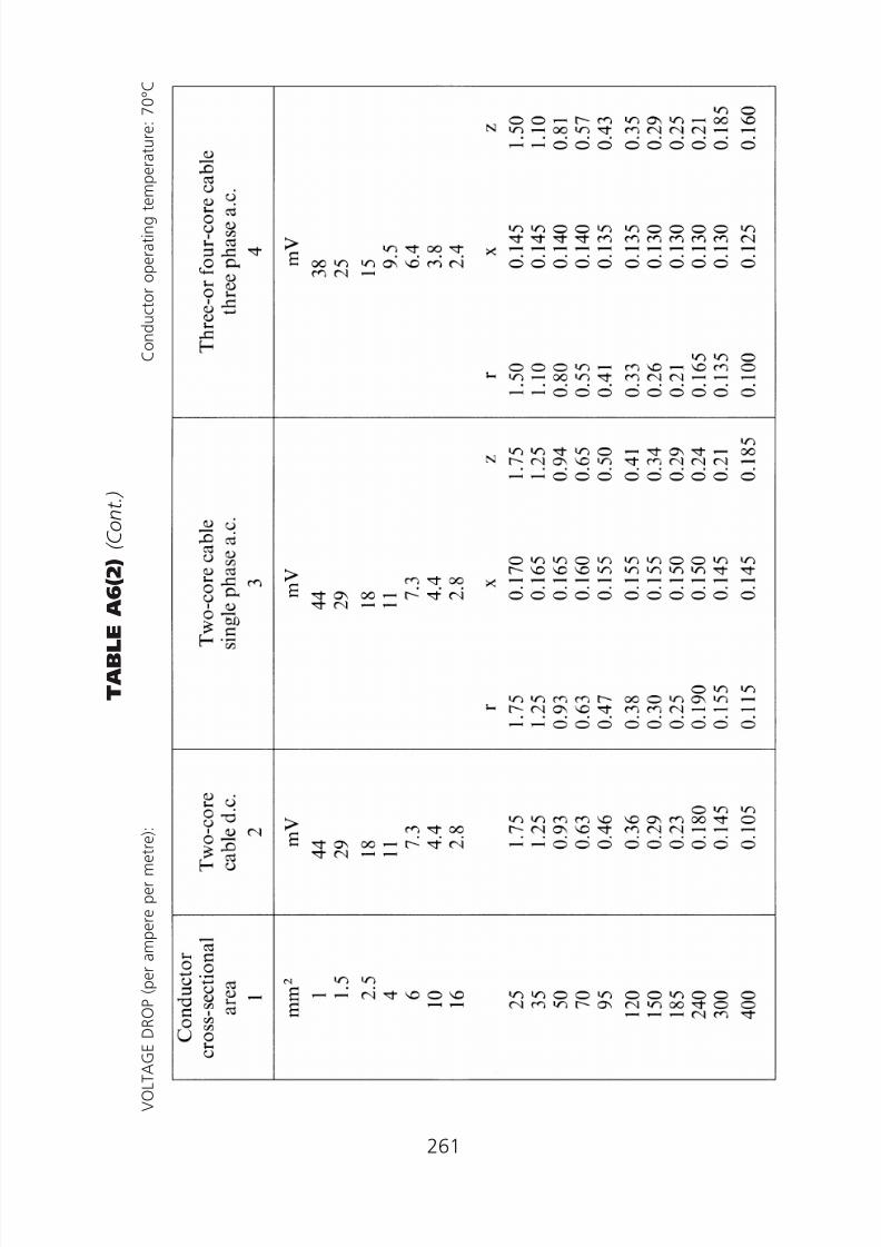
8/23/2019 Electricity Wiring
http://slidepdf.com/reader/full/electricity-wiring 261/337
T A B L E A
6 ( 2 ) ( C o n t . )
V O L T A G E D R O
P ( p e r a m p e r e p e r m e t r e ) :
C o n d u c t o r o p e r a t i n g t e
m p e r a t u r e : 7 0 ° C
261

8/23/2019 Electricity Wiring
http://slidepdf.com/reader/full/electricity-wiring 262/337
T A B L E
A 6 ( 3 )
S i n g l e - c o r e a r m o u r e d P V C i n s u l a t e d c a b l e s
( n o n - m a g n
e t i c a r m o u r )
( C O P P E R C O
N D U C T O R S )
B S
6 3 4 6
A m b i e n t t e
m p e r a t u r e : 3 0 ° C
C U R R E N T C A R
R Y I N G C A P A C I T Y ( A m p e r e s ) :
C o n d u c t o r o p e r a t i n g t e
m p e r a t u r e : 7 0 ° C
262
N O T E :
W h e r
e t h e c o n d u c t o r i s t o b e p r o t
e c t e d b y a s e m i - e n c l o s e d f u s e t o B S 3 0 3 6 , s e e A p p e n d i x 5 ( 4 ) .

8/23/2019 Electricity Wiring
http://slidepdf.com/reader/full/electricity-wiring 263/337
T A B L E A
6 ( 3 ) ( C o n t . )
V O L T A G E D R O
P ( p e r a m p e r e p e r m e t r e ) :
C o n d u c t o r o p e r a t i n g t e
m p e r a t u r e : 7 0 ° C
263
N O T E :
* S p a c i n g s l a r g e r t h a n t h o s e s p e c i f i e d i n M e t h o d 1 2 ( S e e A p p e n
d i x 7 ) w i l l r e s u l t i n l a r g e r v o l t a g e d r o p .
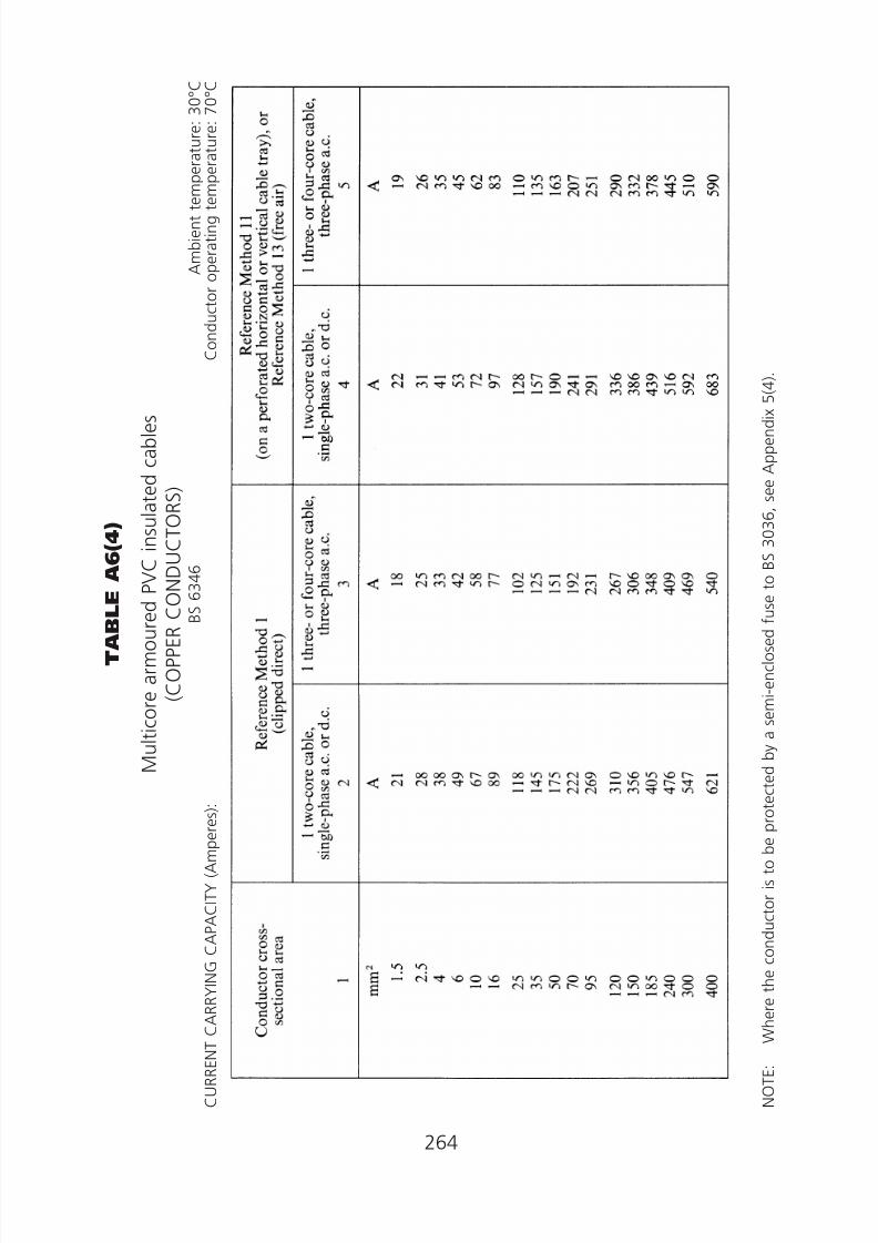
8/23/2019 Electricity Wiring
http://slidepdf.com/reader/full/electricity-wiring 264/337
T A B L E
A 6 ( 4 )
M u l t i c o r e a r m o u r e d
P V C i n s u l a t e d c a b l e s
( C O P P E R C O
N D U C T O R S )
B S
6 3 4 6
A m b i e n t t e
m p e r a t u r e : 3 0 ° C
C U R R E N T C A R
R Y I N G C A P A C I T Y ( A m p e r e s ) :
C o n d u c t o r o p e r a t i n g t e
m p e r a t u r e : 7 0 ° C
264
N O T E :
W h e r
e t h e c o n d u c t o r i s t o b e p r o t
e c t e d b y a s e m i - e n c l o s e d f u s e t o B S 3 0 3 6 , s e e A p p e n d i x 5 ( 4 ) .

8/23/2019 Electricity Wiring
http://slidepdf.com/reader/full/electricity-wiring 265/337
T A B L E A
6 ( 4 ) ( C o n t . )
V O L T A G E D R O
P ( p e r a m p e r e p e r m e t r e ) :
C o n d u c t o r o p e r a t i n g t e
m p e r a t u r e : 7 0 ° C
265

8/23/2019 Electricity Wiring
http://slidepdf.com/reader/full/electricity-wiring 266/337
T A B L E
A 6 ( 5 )
S i n g l e c o r e X
L P E i n s u l a t e d c a b l e s , n o n - a r m o u r e d , w i t h o r w
i t h o u t s h e a t h
( C O P P E R C O
N D U C T O R S )
B S
7 8 8 9
A m b i e n t t e
m p e r a t u r e : 3 0 ° C
C U R R E N T C A R
R Y I N G C A P A C I T Y ( A m p e r e s ) :
B S
7 2 1 1
C o n d u c t o r o p e r a t i n g t e
m p e r a t u r e : 9 0 ° C
266
N O T E :
1 .
W
h e r e t h e c o n d u c t o r i s t o b e p r o t e c t e d b y a s e m i - e n c l o s e d f u s e t o
B S 3 0 3 6 , s e e A p p e n d i x 5 ( 4 ) .
* 2 .
W
h e r e a c o n d u c t o r o p e r a t e s a t a
t e m p e r a t u r e e x c e e d i n g 7 0 ° C i t s h a l l b e a s c e r t a i n e d t h a t t h e e q u i p
m e n t c o n n e c t e d t o t h e c o n d u c t o
r i s s u i t a b l e f o r t h e
c
o n d u c t o r o p e r a t i n g t e m p e r a t u r e .
3 .
W
h e r e c a b l e s i n t h i s t a b l e a r e c o n n e c t e d t o e q u i p m e n t o r a c c e s s o r i e s d e s i g n e d t o o p e r a t e a t a t e m p e
r a t u r e n o t e x c e e d i n g 7 0 ° C ,
t h e c u r r e n t r a t i n g s g i v e n
i n t h e e q u i v a l e n t t a b l e f o r 7 0 ° C P V C i n s u l a t e d c a b l e s ( B S 6 0 0 4 ,
B S
6 3 4 6 ) s h a l l b e u s e d .
4 .
T
h e c u r r e n t c a r r y i n g c a p a c i t y i n c o
l u m n s 2 t o 5 a r e a l s o a p p l i c a b l e t
o f l e x i b l e c a b l e s t o B S 7 2 1 1 T a b l e
3 ( b ) w h e r e t h e c a b l e s a r e u s e d i n f i x e d i n s t a l l a t i o n s .
5 .
F
o r c a b l e i n r i g i d P V C c o n d u i t , t h e
v a l u e s s t a t e d i n T a b l e A 6 ( 1 ) a r e
a p p l i c a b l e .

8/23/2019 Electricity Wiring
http://slidepdf.com/reader/full/electricity-wiring 267/337
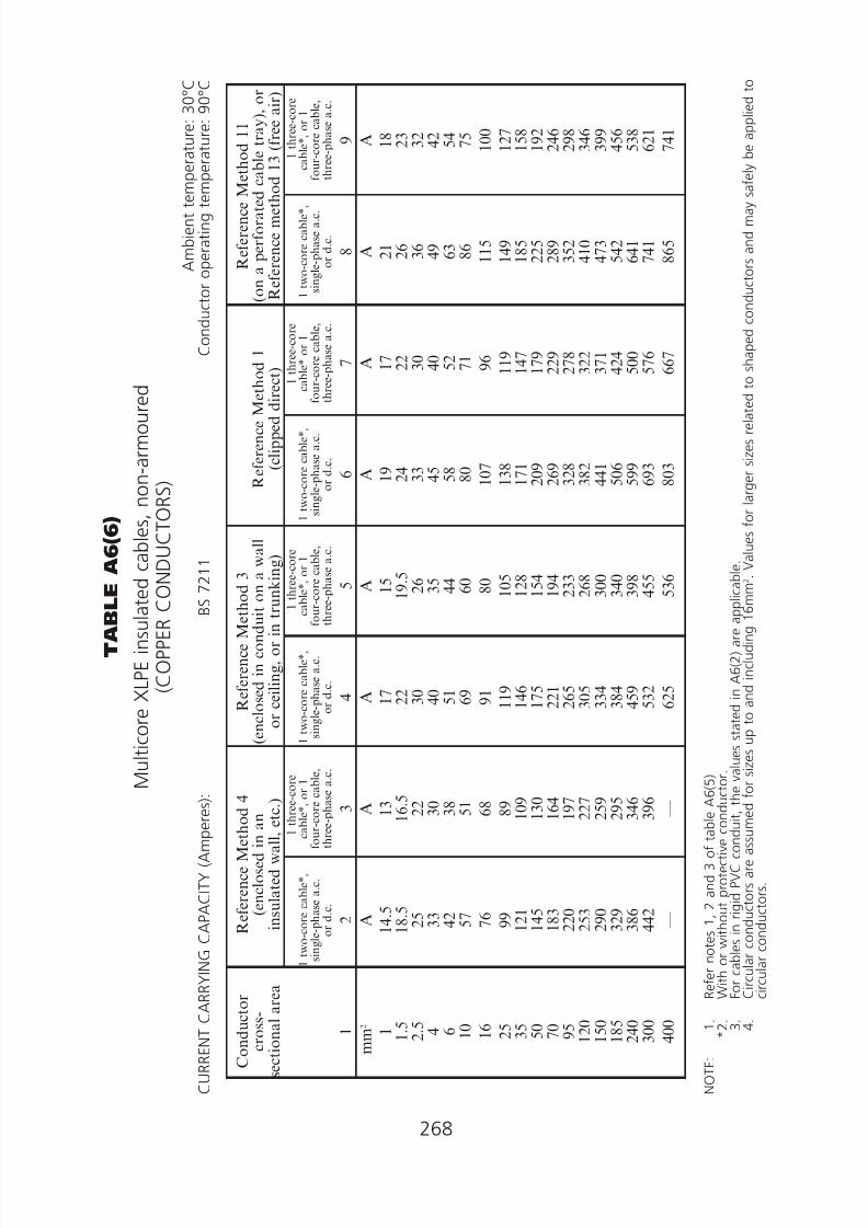
8/23/2019 Electricity Wiring
http://slidepdf.com/reader/full/electricity-wiring 268/337
00
268
T A B L E
A 6 ( 6 )
M u l t i c o r e X L P E i n s u l a t e
d c a b l e s , n o n - a r m o u r e d
( C O P P E R C O
N D U C T O R S )
A m b i e n t t e
m p e r a t u r e : 3 0 ° C
C U R R E N T C A R
R Y I N G C A P A C I T Y ( A m p e r e s ) :
B S
7 2 1 1
C o n d u c t o r o p e r a t i n g t e
m p e r a t u r e : 9 0 ° C
C o n d u c t o r
c r o s s -
s e c t i o n a l a r e
a
1
R e f e r e n c e M e t h o d 4
( e n c l o s e d i n a n
i n s u l a t e d w a l l , e t c . )
R e f e r e n c e M e t h o
d 3
( e n c l o s e d i n c o n d u i t o
n a w a l l
o r c e i l i n g , o r i n t r u n k i n g )
R e f e r e n c e M e
t h o d 1
( c l i p p e d d i r e c t )
R e f e r e n c e M e t h o d 1 1
( o n a p e r f o r a t e d
c a b l e t r a y ) , o r
R e f e r e n c e m e t h
o d 1 3 ( f r e e a i r )
1 t w o - c o r e c a b l e * ,
s i n g l e - p h a s e a . c .
o r d . c .
2
1 t h r e e - c o r e
c a b l e * , o
r 1
f o u r - c o r e c a b l e ,
t h r e e - p h a s e a . c .
3
1 t w o - c o r e c a b l e * ,
s i n g l e - p h a s e a . c .
o r d . c .
4
1 t h r e e - c o r e
c a b l e * , o r 1
f o u r - c
o r e c a b l e ,
t h r e e - p h a s e a . c .
5
1 t w o - c o r e c a b l e * ,
s i n g l e - p h a s e a . c .
o r d . c .
6
1 t h r e e - c o r e
c a b l e * o r 1
f o
u r - c o r e c a b l e ,
t h r e e - p h a s e a . c .
7
1 t w o - c o r e c a b l e * ,
s i n g l e - p h a s e a . c .
o r d . c .
8
1 t h r e e - c o r e
c a b l e * , o r 1
f o u r - c o r e c a b l e ,
t h r e e - p h a s e a . c .
9
m m
2 1 1 . 5
2 . 5 4 6 1 0 1 6 2 5 3 5 5 0 7 0 9 5
1 2 0 1 5 0
1 8 5 2 4 0
3 0 0 4 0 0
A 1 4 . 5
1 8 . 5
2 5 3 3
4 2
5 7 7 6 9 9 1 2 1
1 4 5 1 8 3
2 2 0 2 5 3
2 9 0 3 2 9
3 8 6 4 4 2
—
A 1 3 1 6 . 5 2 2 3 0
3 8
5 1 6 8 8 9 1 0 9 1 3 0 1 6 4 1 9 7 2 2 7 2 5 9 2 9 5 3 4 6 3 9 6 —
A 1 7 2 2 3 0 4 0
5 1
6 9 9 1 1 1 9
1 4 6 1 7 5
2 2 1 2 6 5
3 0 5 3 3 4
3 8 4 4 5 9
5 3 2 6 2 5
A 1 5
1
9 . 5
2 6 3 5
4 4
6 0 8 0 1 0 5
1 2 8 1 5 4
1 9 4 2 3 3
2 6 8 3 0 0
3 4 0 3 9 8
4 5 5 5 3 6
A 1 9 2 4 3 3 4 5
5 8
8 0 1 0 7
1 3 8 1 7 1
2 0 9 2 6 9
3 2 8 3 8 2
4 4 1 5 0 6
5 9 9 6 9 3
8 0 3
A 1 7 2 2 3 0 4 0
5 2
7 1 9 6 1 1 9
1 4 7 1 7 9
2 2 9 2 7 8
3 2 2 3 7 1
4 2 4 5 0 0
5 7 6 6 6 7
A 2 1 2 6 3 6 4 9
6 3
8 6 1 1 5
1 4 9 1 8 5
2 2 5 2 8 9
3 5 2 4 1 0
4 7 3 5 4 2
6 4 1 7 4 1
8 6 5
A 1 8 2 3 3 2 4 2
5 4
7 5 1 0 0
1 2 7 1 5 8
1 9 2 2 4 6
2 9 8 3 4 6
3 9 9 4 5 6
5 3 8 6 2 1
7 4 1
N O T E :
1 .
R
e f e r n o t e s 1 ,
2 a n d 3 o f t a b l e A 6 ( 5 )
* 2 .
W
i t h o r w i t h o u t p r o t e c t i v e c o n d u c t o r .
3 .
F
o r c a b l e s i n r i g i d P V C c o n d u i t , t h
e v a l u e s s t a t e d i n A 6 ( 2 ) a r e a p p l i c a b l e .
4 .
C
i r c u l a r c o n d u c t o r s a r e a s s u m e d f
o r s i z e s u p t o a n d i n c l u d i n g 1 6 m
m 2 .
V a l u e s f o r l a r g e r s i z e s r e l a t e d
t o s h a p e d c o n d u c t o r s a n d m a y s a f e l y b e a p p l i e d t o
c
i r c u l a r c o n d u c t o r s .

8/23/2019 Electricity Wiring
http://slidepdf.com/reader/full/electricity-wiring 269/337
00
T A B L E A
6 ( 6 ) ( C o n t . )
V O L T A G E D R O
P ( p e r a m p e r e p e r m e t r e ) :
C o n d u c t o r o p e r a t i n g t e
m p e r a t u r e : 9 0 ° C
269
C o n d u
c t o r
c r o s s - s e c
t i o n a l
a r e a
1
T w o - c o r e
c a b l e d . c .
2
T w o - c o r e c a b l e
s i n g l e p
h a s e a . c .
3
T h r e e - o r f o u r - c o r e
c a b l e
t h r e e p h a s e a . c
.
4
m m 2 1 1 . 5 2 . 5 4 6 1 0 1 6 2 5 3 5 5 0 7 0 9 5
1 2 0
1 5 0
1 8 5
2 4 0
3 0 0
4 0 0
m V
4 6
3 1 1 9 1 2
7 . 9
4 . 7
2 . 9
1 . 8 5
1 . 3 5
0 . 9 8
0 . 6 7
0 . 4 9
0 . 3 9
0 . 3 1
0 . 2 5
0 . 1 9 5
0 . 1 5 5
0 . 1 2 0
m
V
4 6
3 1
1 9
1 2
7 . 9
4 . 7
2 . 9
r
x
z
1 . 8 5
0 . 1 6 0
1 . 9 0
1 . 3 5
0 . 1 5 5
1 . 3 5
0 . 9 9
0 . 1 5 5
1 . 0 0
0 . 6 7
0 . 1 5 0
0 . 6 9
0 . 5 0
0 . 1 5 0
0 . 5 2
0 . 4 0
0 . 1 4 5
0 . 4 2
0 . 3 2
0 . 1 4 5
0 . 3 5
0 . 2 6
0 . 1 4 5
0 . 2 9
0 . 2 0
0 . 1 4 0
0 . 2 4
0 . 1 6
0 . 1 4 0
0 . 2 1
0 . 1 3
0 . 1 4 0
0 . 1 9 0
m V
4 0
2 7 1 6 1 0
6 . 8
4 . 0
2 . 5
r
x
z
1 . 6 0
0 . 1 4 0
1 . 6 5
1 . 1 5
0 . 1 3 5
1 . 1 5
0 . 8 6
0 . 1 3 5
0 . 8 7
0 . 5 9
0 . 1 3 0
0 . 6 0
0 . 4 3
0 . 1 3 0
0 . 4 5
0 . 3 4
0 . 1 3 0
0 . 3 7
0 . 2 8
0 . 1 2 5
0 . 3 0
0 . 2 2
0 . 1 2 5
0 . 2 6
0 . 1 7 5
0 . 1 2 5
0 . 2 1
0 . 1 4 0
0 . 1 2 0
0 . 1 8 5
0 . 1 1 5
0 . 1 2 0
0 . 1 6 5

8/23/2019 Electricity Wiring
http://slidepdf.com/reader/full/electricity-wiring 270/337
270
T A B L E
A 6 ( 7 )
S i n g l e - c o r e X L P E i n s u l a t e d c a b l e s
( n o n - m a g n
e t i c a r m o u r )
( C O P P E R C O
N D U C T O R S )
B S
5 4 6 7
A m b i e n t t e
m p e r a t u r e : 3 0 ° C
C U R R E N T C A R
R Y I N G C A P A C I T Y ( A m p e r e s ) :
B S
6 7 2 4
C o n d u c t o r o p e r a t i n g t e
m p e r a t u r e : 9 0 ° C
R e f e r e n c e M e t h o d 1
( c l i p p e d d i r e c t )
R e f e r e n c e M e t h o d 1 1
( o n a p e r f o r a t e d
c a b l e t r a y )
R e f e r e n c e M e t h o d 1 2 ( f r e e a i r )
C o n d u c t o r
c r o s s -
s e c t i o n a l a r e a
1
2 c a b l e s ,
s i n g l e - p h a s e
a
. c . o r d . c .
f l a t
a n d t o u c h i n g
2
3 o r 4 c a b l e s ,
t h r e e - p h a s e
a . c . f l a t a n d
t o u c h i n g
3
2 c a b l e s ,
s i n g l e - p h a s e
a . c . f
l a t &
t o u c
h i n g
4
3 o r 4 c a b l e s
t h r e e - p h a s e
a . c . f l a t &
t o u c h i n g
5
2 c a b l e s s i n g l e p h a s e a . c .
2 c a b l e s d . c .
3 o r 4 c a b l e s , t h r e e - p h a s e a . c .
H o r i z o n t a l
f l a t s p a c e d
6
V e r t i c a l f l a t
s p a c e d 7
H o r i z o n t a l
s p a c e d 8
V e r t i c a l
s p a c e d 9
H o r i z o n t a l
f l a t s p a c e d
1 0
V e r t i c a l f l a t
s p a c e d 1 1
3 c a b l e s
t r e f o i l
1 2
m m 2
5 0 7 0 9 5 1 2 0
1 5 0 1 8 5
2 4 0 3 0 0
4 0 0 5 0 0
6 3 0 8 0 0
1 0 0 0
A 2 3 7 3 0 3
3 6 7 4 2 5
4 8 8 5 5 7
6 5 6 7 5 5
8 5 3 9 6 2
1 0 8 2
1 1 7 0
1 2 6 1
A 2 2 0 2 7 7
3 3 3 3 8 3
4 3 7 4 9 6
5 7 9 6 6 2
7 1 7 7 9 1
8 6 1 9 0 4
9 6 1
A 2 5
3
3 2
2
3 8
9
4 4
9
5 1
6
5 8
7
6 8
9
7 9
2
8 9
9
1 0 1
6
1 1 4
6
1 2 4
6
1 3 4
5
A 2 3 2 2 9 3
3 5 2 4 0 5
4 6 2 5 2 4
6 1 2 7 0 0
7 6 7 8 5 1
9 3 5 9 8 7
1 0 5 5
A 2 8 2 3 5 7
4 3 6 5 0 4
5 6 6 6 4 3
7 4 9 8 4 2
9 2 9
1 0 3 2
1 1 3 9
1 2 0 4
1 2 8 9
A 2 6 6 3 3 7
4 1 2 4 7 7
5 3 9 6 1 4
7 1 4 8 0 5
8 8 9 9 8 9
1 0 9 2
1 1 5 5
1 2 3 8
A 2 8 4 3 5 6
4 4 6 5 1 9
6 0 0 6 8 8
8 1 5 9 4 3
1 1 3 7
1 3 1 4
1 5 2 8
1 8 0 9
2 1 0 0
A 2 7 0
3 4 9
4 2 6
4 9 7
5 7 5
6 6 0
7 8 2
9 0 6
1
0 9 4
1
2 6 6
1
4 7 4
1
7 4 4
2
0 2 6
A 2 8 8 3 5 8
4 2 5 4 8 5
5 4 9 6 1 8
7 1 5 8 1 0
8 4 8 9 2 3
9 9 2
1 0 4 2
1 1 1 0
A 2 6 6 3 3 1 3 9 3 4 4 9 5 1 0 5 7 4 6 6 6 7 5 5 7 9 7 8 7 1 9 4 0 9 7 8 1 0 4 1
A 2 2 2 2 8 5
3 4 6 4 0 2
4 6 3 5 2 9
6 2 5 7 2 0
8 1 5 9 1 8
1 0 2 7
1 1 1 9
1 2 1 4
N O T E :
R e f e r
N o t e s 1 ,
2 a n d 3 o f t a b l e A 6
( 5 ) .

8/23/2019 Electricity Wiring
http://slidepdf.com/reader/full/electricity-wiring 271/337
00
0
0
0
0
0
0
0
0
0
0
0
0
00
0
0
0
0
0
0
0
0
0
0
0
0
00
0
0
0
0
0
0
0
0
0
0
0
0
0
0
0
0
0
0
0
0
0
0
0
0
0
0
0
0
0
0
0
0
0
0
0
0
0
0
0
0
0
0
0
0
0
0
0
0
0
0
0
0
0
0
0
0
0
0
0
0
0
0
0
0
0
0
0
0
0
0
0
0
0
0
0
0
T A B L E A
6 ( 7 ) ( C o n t . )
V O L T A G E D R O
P ( p e r a m p e r e p e r m e t r e ) :
C o n d u c t o r o p e r a t i n g t e
m p e r a t u r e : 9 0 ° C
271
C o n
d u c t o r
c r o s s -
s e c t i o n a l
a r e a 1
2 c a b l e s
d . c . 2
2 c a b l e s — s i n g l e p h a s e a . c .
3 o r 4
c a b l e s — t h r e e p h a s e a . c .
R e f e r e n c e M e t h o
d s 1
& 1 1
( T o u c h i n g )
3
R e f e r e n c e M e t h o d 1 2
( S p a c e d * )
4
R e f e r e n c e M e t h o d s 1 ,
1 1 a n d 1 2
( i n t r e f o i l t o u c h i n g )
5
R e f e r e n c e M e t h o d s 1
& 1 1
( F l a t a n d t o u c h i n g )
6
R e f e r e n c e m e t h o d 1 2
( F l a t s p a c e d * )
7
m m 2
5 0 7 0 9 5 1 2 0
1 5 0 1 8 5
2 4 0 3 0 0
4 0 0 5 0 0
6 3 0 8 0 0
1 0 0 0
m V
0 . 9 8
0 . 6 7
0 . 4 9
0 . 3 9
0 . 3 1
0 . 2 5
0 . 1 9 5
0 . 1 5 5
0 . 1 1 5
0 . 0 9 3
0 . 0 7 3
0 . 0 5 6
0 . 0 4 5
m V
r
x
z
0 . 9 9
0 . 2 1 1
. 0 0
0 . 6 8
0 . 2 0 0
. 7 1
0 . 5 1
0 . 1 9 5 0
. 5 5
0 . 4 1
0 . 1 9 0 0
. 4 5
0 . 3 3
0 . 1 8 5 0
. 3 8
0 . 2 7
0 . 1 8 5 0
. 3 3
0 . 2 1
0 . 1 8 0 0
. 2 8
0 . 1 7
0 . 1 7 5 0
. 2 5
0 . 1 4 5
0 . 1 7 0 0
. 2 2
0 . 1 2 5
0 . 1 7 0 0
. 2 1
0 . 1 0 5
0 . 1 6 5 0
. 1 9 5
0 . 0 9 0
0 . 1 6 0 0
. 1 9 0
0 . 0 9 2
0 . 1 5 5 0
. 1 8 0
m V
r
x
z
0 . 9 8
0 . 2 9
1 . 0 0
0 . 6 9
0 . 2 9
0 . 7 5
0 . 5 3
0 . 2 8
0 . 6 0
0 . 4 3
0 . 2 7
0 . 5 1
0 . 3 6
0 . 2 7
0 . 4 5
0 . 3 0
0 . 2 6
0 . 4 0
0 . 2 4
0 . 2 6
0 . 3 5
0 . 1 9 5
0 . 2 5
0 . 3 2
0 . 1 8 0
0 . 2 4
0 . 3 0
0 . 1 6 5
0 . 2 4
0 . 2 9
0 . 1 5 0
0 . 2 3
0 . 2 7
0 . 1 4 5
0 . 2 3
0 . 2 7
0 . 1 4 0
0 . 2 1
0 . 2 5
m V
r
x
z
0 . 8 6
0 . 1 8
0 . 8 7
0 . 5 9
0 . 1 7
0 . 6 2
0 . 4 4
0 . 1 7
0 . 4 7
0 . 3 5
0 . 1 6 5
0 . 3 9
0 . 2 9
0 . 1 6 0
0 . 3 3
0 . 2 3
0 . 1 6 0
0 . 2 8
0 . 1 8
0 . 1 5 5
0 . 2 4
0 . 1 4 5
0 . 1 5 0
0 . 2 1
0 . 1 2 5
0 . 1 5 0
0 . 1 9 5
0 . 1 0 5
0 . 1 4 5
0 . 1 8 0
0 . 0 9 2
0 . 1 4 5
0 . 1 7 0
0 . 0 8 6
0 . 1 4 0
0 . 1 6 5
0 . 0 8 0
0 . 1 3 5
0 . 1 5 5
m V
r
x
z
0 . 8 4
0 . 2 5
0 . 8 8
0 . 6 0
0 . 2 5
0 . 6 5
0 . 4 6
0 . 2 4
0 . 5 2
0 . 3 8
0 . 2 4
0 . 4 4
0 . 3 1
0 . 2 3
0 . 3 9
0 . 2 6
0 . 2 3
0 . 3 4
0 . 2 1
0 . 2 2
0 . 3 0
0 . 1 7
0 . 2 2
0 . 2 8
0 . 1 6
0 . 2 1
0 . 2 7
0 . 1 4 5
0 . 2 0
0 . 2 5
0 . 1 3 5
0 . 1 9 5
0 . 2 4
0 . 1 3 0
0 . 1 8 0
0 . 2 3
0 . 1 2 5
0 . 1 7 0
0 . 2 1
m V
r
x
z
0 . 8 4
0 . 3 3
0 . 9 0
0 . 6 2
0 . 3 2
0 . 7 0
0 . 4 9
0 . 3 1
0 . 5 8
0 . 4 1
0 . 3 0
0 . 5 1
0 . 3 4
0 . 2 9
0 . 4 5
0 . 2 9
0 . 2 9
0 . 4 1
0 . 2 4
0 . 2 8
0 . 3 7
0 . 2 0
0 . 2 7
0 . 3 4
0 . 2 0
0 . 2 7
0 . 3 3
0 . 1 9
0 . 2 4
0 . 3 1
0 . 1 7 5
0 . 2 3
0 . 2 9
0 . 1 7 5
0 . 1 9 5
0 . 2 6
0 . 1 6 5
0 . 1 8 0
0 . 2 4
N O T E :
* S p a c i n g s l a r g e r t h a n t h o s e s p e c i f i e d i n M e t h o d 1 2 ( S e e A p p e n
d i x 7 ) w i l l r e s u l t i n l a r g e r v o l t a g e d r o p .

8/23/2019 Electricity Wiring
http://slidepdf.com/reader/full/electricity-wiring 272/337
272
T A B L E
A 6 ( 8 )
M u l t i c o r e a r m o u r e d
X L P E i n s u l a t e d c a b l e s
( C O P P E R C O
N D U C T O R S )
B S
5 4 6 7
A m b i e n t t e
m p e r a t u r e : 3 0 ° C
C U R R E N T C A R
R Y I N G C A P A C I T Y ( A m p e r e s ) :
B S
6 7 2 4
C o n d u c t o r o p e r a t i n g t e
m p e r a t u r e : 9 0 ° C
C o n d u c
t o r c r o s s -
s e c t i o n a l a r e a
1
R e f e r e n c e M e t h o d 1
( c l i p p e d d i r e c t )
R e f e r e n c e M e t h o d 1 1
( o n a p e r f o r a t e d h o r i z o n t a l o r v e r t i c a l c
a b l e t r a y ) , o r
R e f e r e n c e M e t h o d 1 3 ( f r e e a
i r )
1 t w o - c
o r e c a b l e ,
s i n g l e - p h a s e a . c . o r d . c .
2
1 t h r e e o r f o u r - c o r e c a b l e ,
t h r e e - p
h a s e a . c .
3
1 t w o - c
o r e c a b l e ,
s i n g l e - p h a s e a . c . o r d . c .
4
1 t h r e e - o r f
o u r - c o r e c a b l e ,
t h r e e - p h a s e a . c .
5
m
m 2
1 . 5
2 . 5 4 6 1 0 1 6 2 5 3 5 5 0 7 0 9 5
1
2 0
1
5 0
1
8 5
2
4 0
3
0 0
4
0 0
A 2 7 3 6 4 9
6 2
8 5 1 1 0
1 4 6 1 8 0
2 1 9 2 7 9
3 3 8 3 9 2
4 5 1 5 1 5
6 0 7 6 9 8
7 8 7
A 2 3 3 1 4 2
5 3
7 3 9 4 1 2 4
1 5 4 1 8 7
2 3 8 2 8 9
3 3 5 3 8 6
4 4 1 5 2 0
5 9 9 6 7 3
A 2 9 3 9 5 2
6 6
9 0 1 1 5
1 5 2 1 8 8
2 2 8 2 9 1
3 5 4 4 1 0
4 7 2 5 3 9
6 3 6 7 3 2
8 4 7
A 2 5 3 3 4 4 5 6 7 8 9 9
1 3 1 1 6 2
1 9 7 2 5 1
3 0 4 3 5 3
4 0 6 4 6 3
5 4 6 6 2 8
7 2 8
N O T E :
R e f e r
N o t e s 1 ,
2 a n d 3 o f t a b l e A 6
( 5 ) .
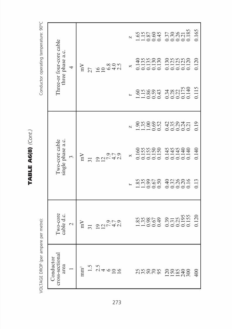
8/23/2019 Electricity Wiring
http://slidepdf.com/reader/full/electricity-wiring 273/337
00
T A B L E A
6 ( 8 ) ( C o n t . )
V O L T A G E D R O
P ( p e r a m p e r e p e r m e t r e ) :
C o n d u c t o r o p e r a t i n g t e
m p e r a t u r e : 9 0 ° C
273
C o n d u
c t o r
c r o s s - s e c
t i o n a l
a r e a
1
T w o - c o r e
c a b l e d . c .
2
T w o - c o r e c a b l e
s i n g l e p
h a s e a . c .
3
T h r e e - o r f o u r - c o r e
c a b l e
t h r e e p h a s e a . c
.
4
m m 2 1 . 5 2 . 5 4 6 1 0 1 6 2 5 3 5 5 0 7 0 9 5
1 2 0
1 5 0
1 8 5
2 4 0
3 0 0
4 0 0
m V
3 1 1 9 1 2
7 . 9
4 . 7
2 . 9
1 . 8 5
1 . 3 5
0 . 9 8
0 . 6 7
0 . 4 9
0 . 3 9
0 . 3 1
0 . 2 5
0 . 1 9 5
0 . 1 5 5
0 . 1 2 0
m
V
3 1
1 9
1 2
7 . 9
4 . 7
2 . 9
r
x
z
1 . 8 5
0 . 1 6 0
1 . 9 0
1 . 3 5
0 . 1 5 5
1 . 3 5
0 . 9 9
0 . 1 5 5
1 . 0 0
0 . 6 7
0 . 1 5 0
0 . 6 9
0 . 5 0
0 . 1 5 0
0 . 5 2
0 . 4 0
0 . 1 4 5
0 . 4 2
0 . 3 2
0 . 1 4 5
0 . 3 5
0 . 2 6
0 . 1 4 5
0 . 2 9
0 . 2 0
0 . 1 4 0
0 . 2 4
0 . 1 6
0 . 1 4 0
0 . 2 1
0 . 1 3
0 . 1 4 0
0 . 1 9
m V
2 7 1 6 1 0
6 . 8
4 . 0
2 . 5
r
x
z
1 . 6 0
0 . 1 4 0
1 . 6 5
1 . 1 5
0 . 1 3 5
1 . 1 5
0 . 8 6
0 . 1 3 5
0 . 8 7
0 . 5 9
0 . 1 3 0
0 . 6 0
0 . 4 3
0 . 1 3 0
0 . 4 5
0 . 3 4
0 . 1 3 0
0 . 3 7
0 . 2 8
0 . 1 2 5
0 . 3 0
0 . 2 2
0 . 1 2 5
0 . 2 6
0 . 1 7 5
0 . 1 2 5
0 . 2 1
0 . 1 4 0
0 . 1 2 0
0 . 1 8 5
0 . 1 1 5
0 . 1 2 0
0 . 1 6 5

8/23/2019 Electricity Wiring
http://slidepdf.com/reader/full/electricity-wiring 274/337
274

8/23/2019 Electricity Wiring
http://slidepdf.com/reader/full/electricity-wiring 275/337
275

8/23/2019 Electricity Wiring
http://slidepdf.com/reader/full/electricity-wiring 276/337
276

8/23/2019 Electricity Wiring
http://slidepdf.com/reader/full/electricity-wiring 277/337
277
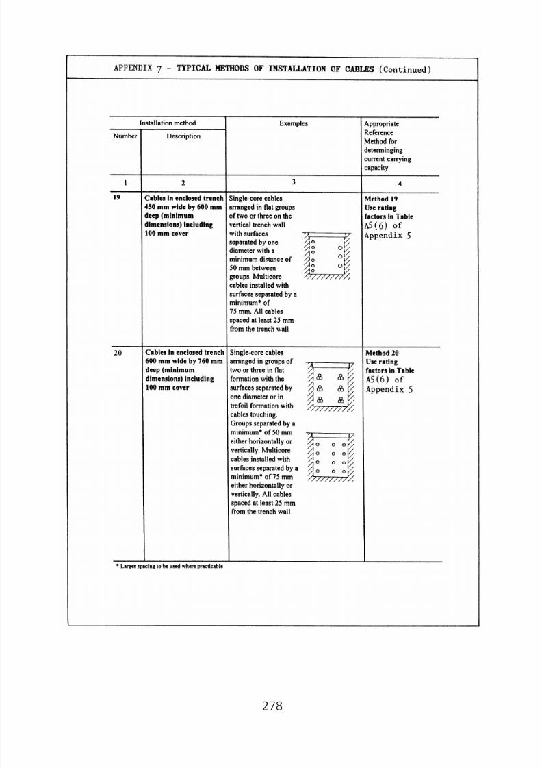
8/23/2019 Electricity Wiring
http://slidepdf.com/reader/full/electricity-wiring 278/337
278

8/23/2019 Electricity Wiring
http://slidepdf.com/reader/full/electricity-wiring 279/337
Appendix 8
Graphical Symbols for Electrical Diagrams
279

8/23/2019 Electricity Wiring
http://slidepdf.com/reader/full/electricity-wiring 280/337
Contactor
Main make contact of a contactor
(contact open in the unoperated position
Contactor with automatic tripping initiated
by a built-in measuring relay or release
Contactor
Main break contact of a contactor
(contact closed in the unoperated position)
Two-way disconnector (isolator) with off-
position in the centre
Switch-disconnector with automatic tripping
initiated by a built-in measuring relay or
release
Fuse, general symbol
280

8/23/2019 Electricity Wiring
http://slidepdf.com/reader/full/electricity-wiring 281/337
281

8/23/2019 Electricity Wiring
http://slidepdf.com/reader/full/electricity-wiring 282/337
Junction, connection point
282

8/23/2019 Electricity Wiring
http://slidepdf.com/reader/full/electricity-wiring 283/337
No. Symbol Description
35.
Motor starter, general symbol
Note – Qualifying symbols may be showninside the general symbol toindicate particular types ofstarters
36.
Starter operated in steps
Note – The number of steps may beindicated
37.
Star-delta starter
38.
Auto-transformer starter
39.
Direct-on-line starter with contactorfor reversing the rotation of a motor
40.
Starter-regulator with thyristors
41.
Machine, general symbol
The asterisk* shall be replaced by aletter designation as follows:
C Synchronous converter
G Generator
GS Synchronous generator
M Motor
MG Machine capable of use as agenerator or motor
MS Synchronous motor
42.
Switch, general symbol
43.
Switch with pilot light
44.
Switch, two pole
283

8/23/2019 Electricity Wiring
http://slidepdf.com/reader/full/electricity-wiring 284/337
No. Symbol Description
45.
Pull-cord switch, single pole
46.
Two-way switch
47.
Intermediate switch
48.
Time switch
49.
Period limiting switch, single pole
50.
Dimmer
51.
Push-button
52.
Socket outlet (power), general symbol
Receptacle outlet (power), generalsymbol
53.
54.
Form 1
Form 2
Multiple socket outlet (power)
The symbol is shown with three outlets.
55.
Socket outlet (power) with protectivecontact
284

8/23/2019 Electricity Wiring
http://slidepdf.com/reader/full/electricity-wiring 285/337
No. Symbol Description
56.
Socket outlet (power) with shutter
57.
Socket outlet (power) with single-pole
switch
58.
Socket outlet (power) with interlocked
switch
59.
Socket outlet (power) with isolatingtransformer, for exampl: shaver outlet
60.
61.
Multipole plug and socket, shown with
six poles: multi-line representation
Single-line representation
62.
63.
64.
Luminaire, fluorescent lamp, general
symbol
Example:
Luminaire with three fluorescent tubes
Luminaire with three fluorescent tubes,simplified representation
65.
Auxilliary apparatus for discharge lamp
Note – Use only when the auxilliaryapparatus is not incorporated inthe luminaire
66.
Self-contained emergency luminaire
67.
Signal lamp
285
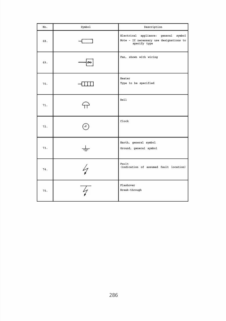
8/23/2019 Electricity Wiring
http://slidepdf.com/reader/full/electricity-wiring 286/337
No. Symbol Description
68.
Electrical appliance: general symbol
Note – If necessary use designations tospecify type
69.
Fan, shown with wiring
70.
Heater
Type to be specified
71.
Bell
72.
Clock
73.
Earth, general symbol
Ground, general symbol
74.
Fault(indication of assumed fault location)
75.
Flashover
Break-through
286

8/23/2019 Electricity Wiring
http://slidepdf.com/reader/full/electricity-wiring 287/337
Appendix 9
Performance Monitoring Points System for Registered Electrical Workers / Contractors
The system, which is administered by the Director of Electrical and MechanicalServices (DEMS), serves to monitor the performance of registered electricalworkers (REW) / registered electrical contractors (REC) to ensure that theelectrical work undertaken by them / registered electrical worker employed byhim/her is in compliance with the Electricity Ordinance (Chapter 406), inparticular the Electricity (Wiring) Regulations. It provides administrativeguidelines to DEMS to take appropriate action to improve the performance ofREW/REC.
Further details can be found at the EMSD website:
REW:
www.emsd.gov.hk -> Protecting Public Safety -> Electricity ->Publications -> Guidance Notes / Guidelines -> Notes for Registered ElectricalWorkers -> PMPS for Registered Electrical Workers
REC:
www.emsd.gov.hk -> Protecting Public Safety -> Electricity ->Publications -> Guidance Notes / Guidelines -> Notes for Registered ElectricalContractors -> PMPS for Registered Electrical Contractors
287
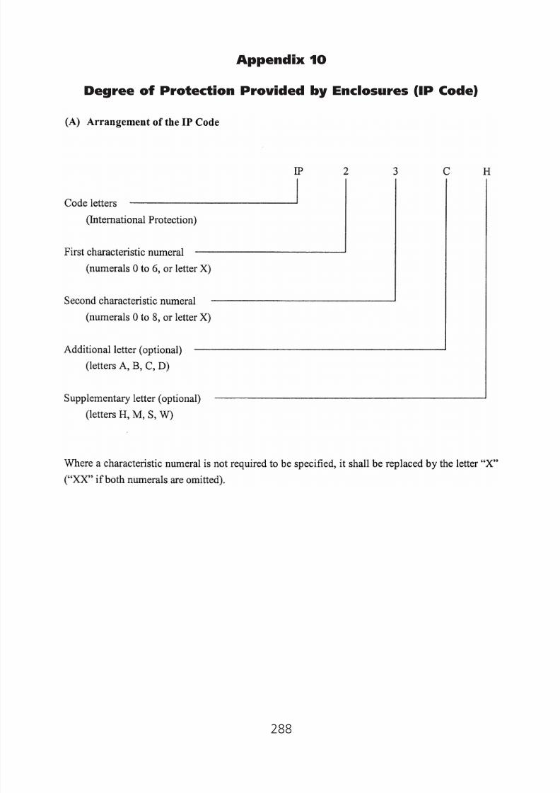
8/23/2019 Electricity Wiring
http://slidepdf.com/reader/full/electricity-wiring 288/337
Appendix 10
Degree of Protection Provided by Enclosures (IP Code)
288

8/23/2019 Electricity Wiring
http://slidepdf.com/reader/full/electricity-wiring 289/337
(Note: The information above is extracted from IEC 60529 ed.2.1 “Copyright©2001 IEC Geneva,Switzerland.www.iec.ch”.)
289
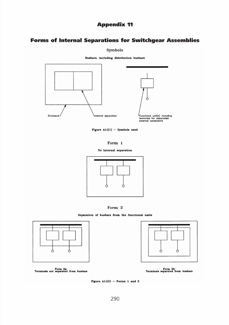
8/23/2019 Electricity Wiring
http://slidepdf.com/reader/full/electricity-wiring 290/337
Appendix 11
Forms of Internal Separations for Switchgear Assemblies
290
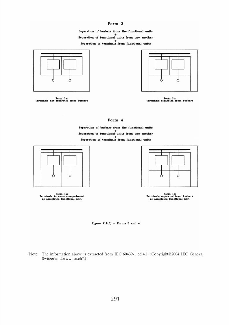
8/23/2019 Electricity Wiring
http://slidepdf.com/reader/full/electricity-wiring 291/337
(Note: The information above is extracted from IEC 60439-1 ed.4.1 “Copyright©2004 IEC Geneva,Switzerland.www.iec.ch”.)
291

8/23/2019 Electricity Wiring
http://slidepdf.com/reader/full/electricity-wiring 292/337
Appendix 12
Worked Examples for Application of the CoP
(A) General application of the CoP in the design of wiring
installation of a typical dwelling
1. Objective
This worked example shows the general application of the CoP in thedesign of the wiring installation for an individual dwelling.
2. Assumed data of the dwelling
(i) Number of bedrooms = 2
(ii) Size of each bedroom = 7 m2
(iii) Size of living room = 16 m2
(iv) Size of kitchen = 4.5 m2
(v) Steel conduit wiring system to be used
3. Final circuits for the dwelling
(a) The following socket outlets are required (Table 26(1) )—
(i) 3 socket outlets for each bedroom;
(ii) 7 socket outlets for the living room; and(iii) 4 socket outlets for the kitchen.
(b) Other outlets required—
(i) Three connector units controlled by 20A double-pole switches,one for an air-conditioner installed in the living room, two forair-conditioners in the bedrooms.
(ii) 6 fixed lighting points (1 for each bedroom, 2 for the livingroom, 1 for the kitchen and 1 for the bathroom).
(c ) Final circuits required for subparagraphs (a) and (b) are shownbelow—
(i) A 30A ring final circuit using 13A socket outlets serving theliving room and the bedrooms.
(ii) A 30A ring final circuit using 13A socket outlets serving thekitchen.
(iii) A 20A exclusive radial final circuit for an air-conditioner in theliving room (Code 26A(4)).
(iv) A 15A exclusive radial final circuit for an air-conditioner in eachbedroom (Code 26A(4)).
(v) Two 5A radial final circuits for lighting points (one of them isalso for door bell).
292

8/23/2019 Electricity Wiring
http://slidepdf.com/reader/full/electricity-wiring 293/337
0
(d ) Size of PVC insulated copper cables are determined as follows—
(i) 1.5 mm2 for lighting circuit (Table 13(1));
(ii) 2.5 mm2 for radial final circuits to the air-conditioners (Table13(1));
(iii) 2.5 mm2 for ring final circuits using 13A socket outlets (Table6(1)).
(e) For prevention of dangerous earth leakage current, the ring finalcircuits using socket outlets are connected to a residual currentdevice (RCD) having a rated operating current not exceeding 30 mA.(Code 11J(2)(b) ).
(f ) The current demand on the RCD is 42A (Table 7(1), item 12)including—
(i) one 30A ring final circuit using 13A socket outlets;
(ii) 0.4 of the other 30A ring final circuit using 13A socket outlets.
( g) to meet the current demand of ( f ) a 60A RCD is to be used.
4. Current demand and the size of main switch and cable of the dwelling
(a) The current demand of the dwelling is calculated as follows (Table7(1))—
Final Circuit Demeand (A)
(i) Lighting: 0.66 × 0.45A (Code 7B(3)(b)(ii)) × 6 = 1.78(ii) Air-conditioners: 12A (f.l. of a/c in living room)
+ 2 × 0.4 × 5A (f.l. of a/c in bedrooms) = 16
(iii) Final circuits for socket outlets (subparagraph(3)( f ) ) = 42
(b) The minimum size of main switch for the dwelling to meet themaximum demand of 59.78A is 60A.
(c ) the size of the main cable is 16 mm2 (Table 13(1)).
5. MCB Board
A 8 way single pole and neutral MCB board with split busbarsincorporating a RCD is used to connect these final circuits.
6. Size of protective conductors for each dwelling
(a) Steel conduits are used as circuit protective conductors for thedwelling.
(b) 6 mm2 PVC insulated copper cables as main equipotential bondingconductors are used to bond the main gas pipe and the main waterpipe to the main earthing terminal of the MCB board (Code 11E(d ) ).
293
8/23/2019 Electricity Wiring
http://slidepdf.com/reader/full/electricity-wiring 294/337
(c ) 4 mm2 PVC insulated copper cables as supplementary bondingare used to bond the window frames intended to supportair-conditioners.
(B) Example in steps of sizing cable conductors asdescribed in Code 13A(3)
1. Assumed data
An immersion electric water heater rated at 220V, 2 kW is to be installedusing a 2-core-and-earth PVC-insulated and sheathed, non-armouredcable. The supply will be taken from an existing 15A spare way in aconsumer’s unit containing semi-enclosed (rewirable) fuses to BS3036.The supply cable will run for much of its 14 m length in a roof space
which is thermally insulated with glass fibre. The roof space ambienttemperature is expected to be 35°C in summer and, where leaving theconsumer’s unit, the cable will be bunched with seven other 2 core-andearth cables.
2. Steps in sizing cable conductors
(a) Design current of the circuit
Rated power of the heater 2000
= ———————————– = —— = 9.1ASupply voltage 220
(b) A 15A semi-enclosed (rewirable) fuse to BS3036 is chosen as theovercurrent protective device.
(c ) Current carrying capacity of the conductors is determined byapplying the following correction factors to the current rating of theovercurrent protective device (i.e. 15A):
(i) Ambient temperature factor = 0.97
(From Table A5(2) of Appendix 5, using conditions:Ambient temperature = 35°C
Type of insulation = General purpose PVC)
(ii) Grouping factor = 0.52
(From Table A5(3) of Appendix 5, using conditions:
Number of multicore cable = 8
Reference Method of installation = Bunched and clippeddirect to a non-metallic
surface (Method 1), fromAppendix 7)
294
8/23/2019 Electricity Wiring
http://slidepdf.com/reader/full/electricity-wiring 295/337
(iii) Thermal insulation factor = 0.5
(From Appendix 5(3) and the cable is totally surrounded bythermally insulating material)
(iv) Factor for type of protective devices = 0.725
(From Table A5(5) of Appendix 5 and the type of protectivedevice is semi-enclosed fuse to BS3036)
Current carrying capacity15
of the conductors required = ————————————– A0.97 × 0.52 × 0.5 × 0.725
= 82A
(d ) From Table A6(2) of Appendix 6, size of conductor is chosen to be16 mm2 (using Reference Method 1).
(e) Voltage drop calculation:
Maximum permissible voltage drop = 4% × 220V
(by Code 13A(3)(a)(v) ) = 8.8V
The cable is carrying 9.1A and is 14 m long. From Table A6(2) ofAppendix 6, the voltage drop figure for the 16 mm2 cable is 2.8mV/A/m and so the voltage drop is:
2.8 × 9.1 × 14——————— = 0.36V
1 000
The calculated figure is within the acceptable figure of 8.8V if thevoltage drop between the origin of the installation and the 15A fusedoes not exceed 8.44V (i.e. 8.8V–0.36V).
3. Conclusion
The cable chosen for this example should be a 16 mm2 2-core-and-earth,PVC insulated, PVC sheathed, non-armoured cable.
(C) Determination of Extraneous Conductive Parts
To determine whether conductive parts such as metallic bathroomaccessories, metallic windows or metallic door handles are extraneousconductive part, a measurement should be carried out to measure theinsulation resistance between the conductive part and the main earthingterminal. For a typical single-phase supply system with a nominal supplyvoltage of 220V, if the measured resistance could be maintained at notless than 45,000 Ohm (Note) even under the worst conditions (e.g. highmoisture), the metallic part could be considered as a non-extraneousconductive part.
(Note: This value is approximated based on IEC 60479-1:2005.)
295
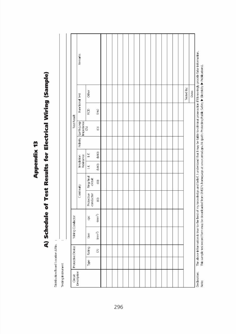
8/23/2019 Electricity Wiring
http://slidepdf.com/reader/full/electricity-wiring 296/337
A p p e n d i x 1 3
A ) S c h e d u l
e o f T e s t R e s u l t s f o r E l e c t r i c a l W i r i n g ( S a m p l e )
296

8/23/2019 Electricity Wiring
http://slidepdf.com/reader/full/electricity-wiring 297/337
___________________
___________________
___________________
___________________
___________________
___________________
___________________
___________________
___________________
___________________
___________________
___________________
Appendix 13
B) Checklists
(Note: For the use of the following five checklists, please refer to Code 22)
Checklist No. 1—Items For New L.V. Installation or ItemsFor Periodic Testing of L.V. Installationsconnected before 1.1.85
Installation Address: __________________________________________
(a) Switchboards, circuit breakers and main switches
(i) No visible damage to impair safety.
(ii) Safe access provided.
(iii) Every circuit breaker, main switch and fuseholder(s) provided with up-to-date, legibleand durable rating labels giving their ratings.
(iv) Every circuit breaker and main switchprovided with a legible and durable
identification label.(v) An up-to-date schematic diagram displayed
to show the main distribution system.
(vi) Link of adequate size installed in neutralcircuit.
(vii) All accessible live parts screened withinsulating plate or earthed metal.
(viii) The overload and fault current protection
characteristics of all circuit breakers verifiedwith secondary injection test instrumentswhere appropriate.
(ix) Lowest insulation resistance being ______Mohms (not less than 1 Mohm) measuredbetween phases/neutral/earth.
(x) All exposed conductive parts effectivelyearthed with a maximum earth fault loopimpedance being ______ ohms.
(b) Busbar trunking system including rising mains
(i) No visible damage to impair safety.
(ii) Phase identification marked on both ends ofmain cable/conductor, and at terminations.
Tested by/Date(N/A if not applicable)
297

8/23/2019 Electricity Wiring
http://slidepdf.com/reader/full/electricity-wiring 298/337
___________________
___________________
___________________
___________________
___________________
___________________
___________________
___________________
___________________
___________________
___________________
___________________
___________________
___________________
___________________
(iii) All joints of metal conduit or trunking to bemechanically sound, electrically continuousand protected against corrosion.
(iv) All accessible live parts screened with aninsulating plate or earthed metal.
(v) Lowest insulation resistance being ______Mohms (not less than 1 Mohm) measuredbetween phases/neutral/earth.
(vi) All metal conduit or trunking effectivelyearthed with a maximum earth fault loopimpedance being ______ ohms.
(c ) Meter board/box
(i) No visible damage to impair safety.
(ii) Safe access provided.
(iii) All exposed metal parts effectively earthedwith a maximum earth fault loop impedance being ______ ohms.
(d ) Overhead lines
(i) No visible damage to impair safety(ii) A minimum height of ______ metres from
ground (not less than 5.8 metres for linesacrossing any place accessible to vehiculartraffic, 5.2 metres in other places or notless than the tallest height restriction of______ metres).
(iii) Lowest insulation resistance being ______Mohms (not less than 1 Mohm) measured
between phases/neutral/earth.(iv) All metal work associated with every steel
pole effectively earthed.
(e) Main cables
(i) No visible damage to impair safety.
(ii) Cables protected against mechanicaldamage.
(iii) Correct phase identification provided atboth ends of the cable.
(iv) Lowest insulation resistance being ______Mohms (not less than 1 Mohm) measuredbetween cores and cores to earth.
Tested by/Date(N/A if not applicable)
298

8/23/2019 Electricity Wiring
http://slidepdf.com/reader/full/electricity-wiring 299/337
___________________
___________________
___________________
___________________
___________________
___________________
___________________
___________________
___________________
___________________
___________________
___________________
___________________
___________________
___________________
(v) All exposed metal parts including the cablearmour effectively earthed with a maximumearth fault loop impedance being ______
ohms.
(f ) Distribution board
(i) No visible damage to impair safety.
(ii) No fuse installed in the neutral circuit.
(iii) All live parts screened with an insulatingplate or earthed metal.
(iv) Phase identification provided on the
distribution board.(v) Insulation resistance of not less than 1
Mohm measured between phases/neutral/ earth.
(vi) All exposed metal parts effectively earthed.
( g) Final circuits
(i) No visible damage to impair safety.
(ii) All non-armoured cables susceptible todamage protected with steel conduit/ trunking. Bushing and rubber grommet,where necessary, provided.
(iii) Conductor sized to suit the rating of thefuse/MCB protecting the circuit.
(iv) No cable joint in final circuit.
(v) All joints of metal conduits or trunking tobe mechanically sound, electricallycontinuous and protected againstcorrosion.
(vi) For temporary installation, cables lying onthe ground or attached to scaffoldingssecured on suitable supports.
(vii) Insulation resistance of not less than 1Mohm measured between phases/neutral/
earth.(viii) All metal conduits, trunking, switch boxes
and exposed metal parts effectivelyearthed.
Tested by/Date(N/A if not applicable)
299

8/23/2019 Electricity Wiring
http://slidepdf.com/reader/full/electricity-wiring 300/337
___________________
___________________
___________________
___________________
___________________
___________________
___________________
___________________
___________________
___________________
___________________
___________________
___________________
___________________
___________________
(ix) Residual current devices function properly.
(x) Earth fault loop impedance and polarities
of every outlet checked.(h) Motors
(i) No visible damage to impair safety.
(ii) Insulation resistance of not less than 1Mohm measured between phases/neutral/ earth.
(iii) All exposed conductive parts effectivelyearthed.
(i) Earthing
(i) No visible damage to impair safety.
(ii) All exposed conductive parts of the wiringinstallation connected to the earthingterminal with appropriate protectiveconductors.
(iii) Bonding/earthing connection to water pipe/
gas pipe/duct effectively connected.
( j ) Neon signs
(i) No visible damage to impair safety.
(ii) The fireman’s switch clearly labelled.
(iii) All high voltage equipment enclosed in anearthed metal box fitted with a ‘DANGER’and ‘危險’ warning notice.
(iv) All live parts screened with an insulationplate or earthed metal.
(v) High voltage cables securely supportedwith glass or glazed porcelain.
(vi) Insulation resistance of the L.V. circuitbeing ______ Mohms (not less than 1Mohm) between phases/neutral/earth.
(vii) All exposed metalwork permanently andeffectively bonded and earthed with amaximum earth fault loop impedance of______ ohms measured at L.V. side.
Tested by/Date(N/A if not applicable)
300

8/23/2019 Electricity Wiring
http://slidepdf.com/reader/full/electricity-wiring 301/337
Checklist No. 2—Additional Items For New L.V. Installationor Items For Periodic Testing of L.V.Installations connected on or after 1.1.85but before 1.6.92
Installation Address: __________________________________________
Tested by/Date(N/A if not applicable)
(a) Earth
(i) A warning notice ‘SAFETY ELEC-TRICALCONNECTION—DO NOT REMOVE’ and ‘安全接地終端——切勿移去’ provided at all
main earthing and bonding connections. ___________________(ii) Main equipotential bonding conductors
effectively connected to main water pipes,main gas pipes, other services pipes/ductingand exposed metallic parts of structuralframework. ___________________
(iii) Supplementary equipotential bondingeffectively provided between exposed
conductive parts and extraneousconductive parts. ___________________
(iv) Exposed conductive parts of fixedequipment installed outside equipotentialzone effectively earthed for the requireddisconnection time. ___________________
(v) Exposed conductive parts of fixedequipment installed within equipotentialzone effectively earthed for the requireddisconnection time. ___________________
(vi) Effectiveness of the main equipotentialbonding connection to the main earthingterminal. ___________________
(vii) Effectiveness of the main equipotentialbonding connection to the lightningprotection system. ___________________
301

8/23/2019 Electricity Wiring
http://slidepdf.com/reader/full/electricity-wiring 302/337
___________________
___________________
___________________
___________________
___________________
___________________
___________________
___________________
___________________
___________________
___________________
___________________
___________________
Checklist No. 3—Additional Items For New L.V. Installationor Items For Periodic Testing of L.V.Installations connected on or after 1.6.92
Installation Address: __________________________________________
(a) Substations
(i) A warning notice ‘DANGER—SUBSTATION, UNAUTHORISED ENTRYPROHIBITED’ and ‘危險——電力分站,未經授權不得內進 ’ provided at everyentrance of substations.
(ii) Suitable locking facilities provided for H.V.substations.
(iii) Suitable lighting provided.
(iv) Suitable ventilation provided.
(v) Entrance/exit free of obstruction.
(b) Switchrooms
(i) A warning notice ‘DANGER—ELECTRICITY,UNAUTHORISED ENTRY PROHIBITED’ and‘危險——有電,未經授權不得內進 ’provided at every entrance of switchrooms.
(ii) Suitable locking facilities provided for H.V.switchrooms.
(iii) Suitable lighting provided.
(iv) Suitable ventilation provided.
(v) Entrance/exit free of obstruction.
(c ) Switchboards, circuit breakers and main switch
An up-to-date notice of periodic inspection andtesting provided at point of supply (i.e. aswitchboard, a circuit breaker or a distributionboard) of the installation.
(d ) Distribution boards
(i) A warning notice ‘DANGER’ and ‘危險’provided on the front panel of everydistribution board.
(ii) A notice of periodic testing provided atnear the main distribution board
incor
orporating a residual current device.
Tested by/Date(N/A if not applicable)
302
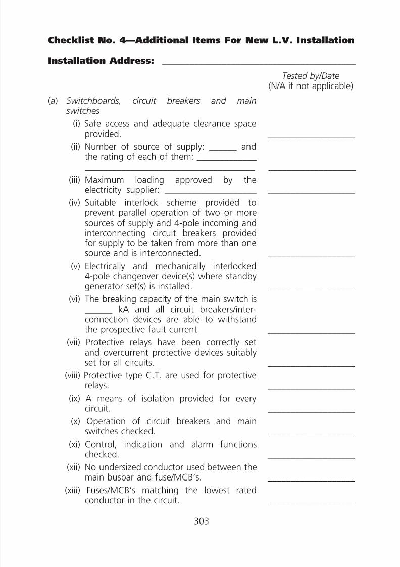
8/23/2019 Electricity Wiring
http://slidepdf.com/reader/full/electricity-wiring 303/337
___________________
_____________________________________ ___________________
___________________
___________________
___________________
___________________
___________________
___________________
___________________
___________________
___________________
___________________
___________________
Checklist No. 4—Additional Items For New L.V. Installation
Installation Address: __________________________________________
(a) Switchboards, circuit breakers and main switches
(i) Safe access and adequate clearance spaceprovided.
(ii) Number of source of supply: ______ andthe rating of each of them: _____________
(iii) Maximum loading approved by theelectricity supplier: ____________________
(iv) Suitable interlock scheme provided toprevent parallel operation of two or moresources of supply and 4-pole incoming andinterconnecting circuit breakers providedfor supply to be taken from more than onesource and is interconnected.
(v) Electrically and mechanically interlocked
4-pole changeover device(s) where standbygenerator set(s) is installed.
(vi) The breaking capacity of the main switch is______ kA and all circuit breakers/interconnection devices are able to withstandthe prospective fault current.
(vii) Protective relays have been correctly setand overcurrent protective devices suitablyset for all circuits.
(viii) Protective type C.T. are used for protectiverelays.
(ix) A means of isolation provided for everycircuit.
(x) Operation of circuit breakers and mainswitches checked.
(xi) Control, indication and alarm functionschecked.
(xii) No undersized conductor used between themain busbar and fuse/MCB’s.
(xiii) Fuses/MCB’s matching the lowest ratedconductor in the circuit.
Tested by/Date(N/A if not applicable)
303

8/23/2019 Electricity Wiring
http://slidepdf.com/reader/full/electricity-wiring 304/337
___________________
___________________
___________________
___________________
___________________
___________________
___________________
___________________
___________________
___________________
___________________
___________________
___________________
___________________
___________________
___________________
(xiv) Suitable cable terminations provided.
(xv) Cable conductors of correct phasesconnected.
(xvi) Single-pole devices for protection orswitching connected in phase conductorsonly.
(b) Busbar trunking system including rising mains
(i) The current rating of the rising mains is______ amperes.
(ii) The rising mains, lateral mains and meterboards positioned at places accessible frompublic area.
(iii) Fire barriers provided where the busbartrunking system passes through floor slabsor walls designated as fire barriers.
(iv) Cables passing through smoke lobbyprotected by enclosures of adequate firerating.
(v) Non-sheathed cables protected by conduit,trunking or ducting.
(vi) Busbar trunking systems, cables andductings adequately supported.
(vii) Armoured cables properly terminated tometal casing or trunking by proper cableglands.
(viii) Suitable cable lugs used for terminatingcables.
(ix) Precaution against corrosion taking onaluminium conductor joined to copper
conductor.(x) Cutout fuses for tapping off supply fitted
with insulated carriers.
(c ) Overhead lines
(i) A steel carrier wire provided between polesto prevent strain on conductor.
(ii) substantial steel poles used to suspendcables crossing vehicular passes.
(iii) Overhead cables supported on suitableinsulators.
304
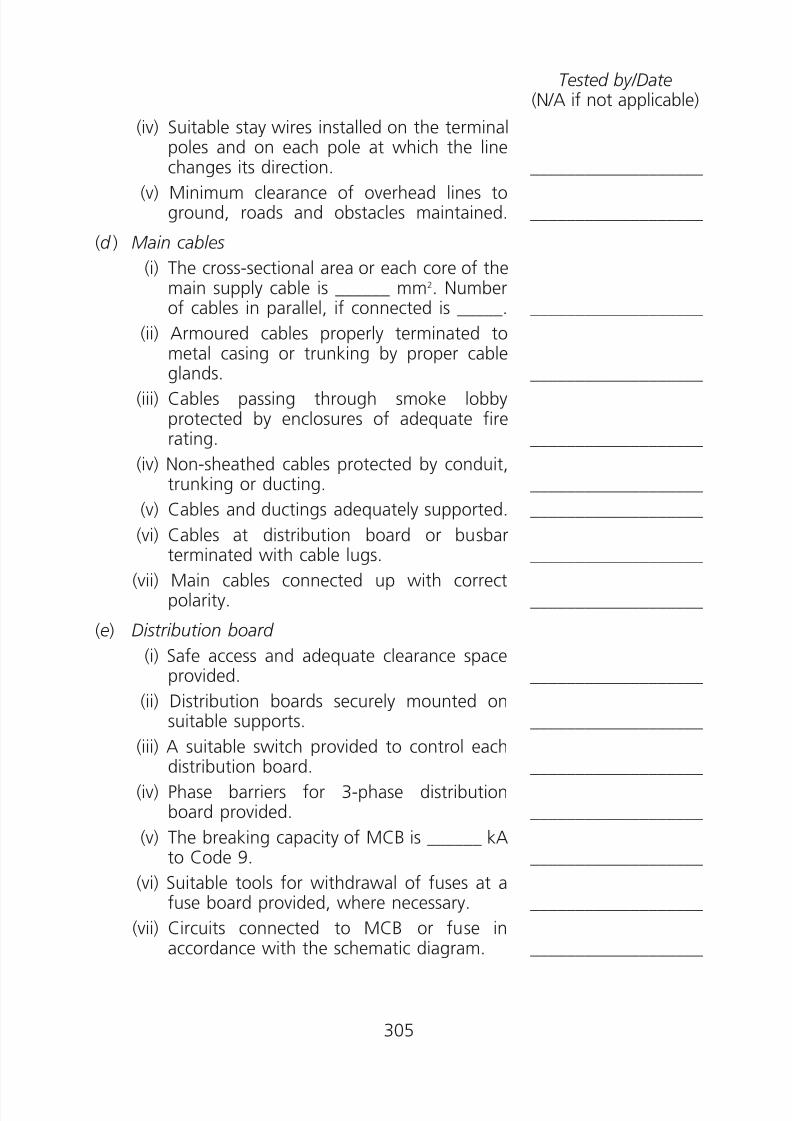
8/23/2019 Electricity Wiring
http://slidepdf.com/reader/full/electricity-wiring 305/337
___________________
___________________
___________________
___________________
___________________
___________________
___________________
___________________
___________________
___________________
___________________
___________________
___________________
___________________
___________________
___________________
(iv) Suitable stay wires installed on the terminalpoles and on each pole at which the linechanges its direction.
(v) Minimum clearance of overhead lines toground, roads and obstacles maintained.
(d ) Main cables
(i) The cross-sectional area or each core of themain supply cable is ______ mm2. Numberof cables in parallel, if connected is _____.
(ii) Armoured cables properly terminated tometal casing or trunking by proper cableglands.
(iii) Cables passing through smoke lobbyprotected by enclosures of adequate firerating.
(iv) Non-sheathed cables protected by conduit,trunking or ducting.
(v) Cables and ductings adequately supported.
(vi) Cables at distribution board or busbarterminated with cable lugs.
(vii) Main cables connected up with correctpolarity.
(e) Distribution board
(i) Safe access and adequate clearance spaceprovided.
(ii) Distribution boards securely mounted on
suitable supports.(iii) A suitable switch provided to control each
distribution board.
(iv) Phase barriers for 3-phase distributionboard provided.
(v) The breaking capacity of MCB is ______ kAto Code 9.
(vi) Suitable tools for withdrawal of fuses at a
fuse board provided, where necessary.(vii) Circuits connected to MCB or fuse in
accordance with the schematic diagram.
Tested by/Date(N/A if not applicable)
305
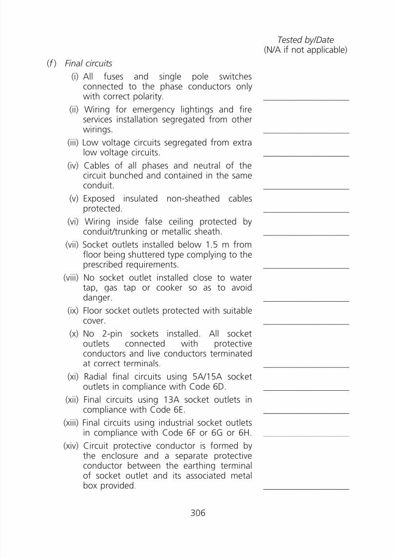
8/23/2019 Electricity Wiring
http://slidepdf.com/reader/full/electricity-wiring 306/337
___________________
___________________
___________________
___________________
___________________
___________________
___________________
___________________
___________________
___________________
___________________
___________________
___________________
___________________
(f ) Final circuits
(i) All fuses and single pole switches
connected to the phase conductors onlywith correct polarity.
(ii) Wiring for emergency lightings and fireservices installation segregated from otherwirings.
(iii) Low voltage circuits segregated from extralow voltage circuits.
(iv) Cables of all phases and neutral of thecircuit bunched and contained in the sameconduit.
(v) Exposed insulated non-sheathed cablesprotected.
(vi) Wiring inside false ceiling protected byconduit/trunking or metallic sheath.
(vii) Socket outlets installed below 1.5 m fromfloor being shuttered type complying to theprescribed requirements.
(viii) No socket outlet installed close to watertap, gas tap or cooker so as to avoiddanger.
(ix) Floor socket outlets protected with suitablecover.
(x) No 2-pin sockets installed. All socketoutlets connected with protectiveconductors and live conductors terminated
at correct terminals.(xi) Radial final circuits using 5A/15A socket
outlets in compliance with Code 6D.
(xii) Final circuits using 13A socket outlets incompliance with Code 6E.
(xiii) Final circuits using industrial socket outletsin compliance with Code 6F or 6G or 6H.
(xiv) Circuit protective conductor is formed by
the enclosure and a separate protectiveconductor between the earthing terminalof socket outlet and its associated metalbox provided.
Tested by/Date(N/A if not applicable)
306
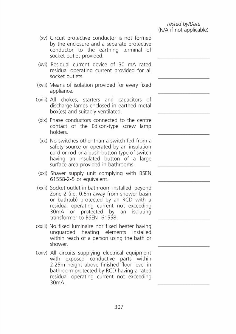
8/23/2019 Electricity Wiring
http://slidepdf.com/reader/full/electricity-wiring 307/337
Tested by/Date(N/A if not applicable)
(xv) Circuit protective conductor is not formedby the enclosure and a separate protectiveconductor to the earthing terminal of
socket outlet provided. ___________________
(xvi) Residual current device of 30 mA ratedresidual operating current provided for allsocket outlets. ___________________
(xvii) Means of isolation provided for every fixedappliance. ___________________
(xviii) All chokes, starters and capacitors ofdischarge lamps enclosed in earthed metalbox(es) and suitably ventilated. ___________________
(xix) Phase conductors connected to the centrecontact of the Edison-type screw lampholders. ___________________
(xx) No switches other than a switch fed from asafety source or operated by an insulationcord or rod or a push-button type of switchhaving an insulated button of a largesurface area provided in bathrooms. ___________________
(xxi) Shaver supply unit complying with BSEN61558-2-5 or equivalent. ___________________
(xxii) Socket outlet in bathroom installed beyondZone 2 (i.e. 0.6m away from shower basinor bathtub) protected by an RCD with aresidual operating current not exceeding30mA or protected by an isolating
transformer to BSEN 61558. ___________________
(xxiii) No fixed luminaire nor fixed heater havingunguarded heating elements installedwithin reach of a person using the bath orshower. ___________________
(xxiv) All circuits supplying electrical equipmentwith exposed conductive parts within2.25m height above finished floor level in
bathroom protected by RCD having a ratedresidual operating current not exceeding30mA. ___________________
307
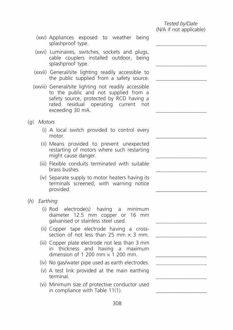
8/23/2019 Electricity Wiring
http://slidepdf.com/reader/full/electricity-wiring 308/337
Tested by/Date(N/A if not applicable)
(xxv) Appliances exposed to weather beingsplashproof type. ___________________
(xxvi) Luminaires, switches, sockets and plugs,cable couplers installed outdoor, beingsplashproof type. ___________________
(xxvii) General/site lighting readily accessible tothe public supplied from a safety source. ___________________
(xxviii) General/site lighting not readily accessibleto the public and not supplied from asafety source, protected by RCD having arated residual operating current notexceeding 30 mA. ___________________
( g) Motors
(i) A local switch provided to control everymotor. ___________________
(ii) Means provided to prevent unexpectedrestarting of motors where such restartingmight cause danger. ___________________
(iii) Flexible conduits terminated with suitablebrass bushes. ___________________
(iv) Separate supply to motor heaters having itsterminals screened, with warning noticeprovided. ___________________
(h) Earthing
(i) Rod electrode(s) having a minimum
diameter 12.5 mm copper or 16 mmgalvanised or stainless steel used. ___________________
(ii) Copper tape electrode having a cross-section of not less than 25 mm × 3 mm. ___________________
(iii) Copper plate electrode not less than 3 mmin thickness and having a maximumdimension of 1 200 mm × 1 200 mm. ___________________
(iv) No gas/water pipe used as earth electrodes. ___________________
(v) A test link provided at the main earthingterminal. ___________________
(vi) Minimum size of protective conductor usedin compliance with Table 11(1). ___________________
308

8/23/2019 Electricity Wiring
http://slidepdf.com/reader/full/electricity-wiring 309/337
___________________
___________________
___________________
___________________
___________________
___________________
___________________
___________________
___________________
___________________
___________________
___________________
___________________
___________________
(vii) Protective conductor up to and including 6mm2 with green and yellow insulationsheath used throughout its length.
(viii) Bonding conductors of ______ mm2 (notless than 150 mm2 copper equivalent) usedfor connection to the earthing terminal ofthe electricity supplier’s transformer(s).
(ix) Bonding conductors of ______ mm2 (notless than 150 mm2 copper equivalent) usedfor connection to the exposed conductiveparts of the electricity supplier’s
underground cable(s).(x) Copper links provided at joints of metallic
trunking which forms part of a protectiveconductor.
(xi) Separate protective conductors providedfor all flexible conduits.
(i ) Lightning Protection
(i) Air termination network/down conductor/
earth termination network having goodcontinuity.
(ii) Joints and connections are mechanicallyand electrically sound.
(iii) Connection link to the main earthingterminal provided.
(iv) Test joint provided.
(v) Rod electrode(s) having a minimum
diameter 12.5 mm copper or 16 mmgalvanised or stainless steel used.
(vi) Copper tape electrode having a cross-section of not less than 25 mm × 3 mm.
(vii) Copper plate electrode not less than 3 mmin thickness and having a maximumdimension of 1 200 mm × 1 200 mm.
(viii) No gas/water pipe used as earth electrodes.
(ix) Measured earth termination network
resistance to earth not more than 10 Ohmwhen the connection to main earthingterminal disconnected.
Tested by/Date(N/A if not applicable)
309
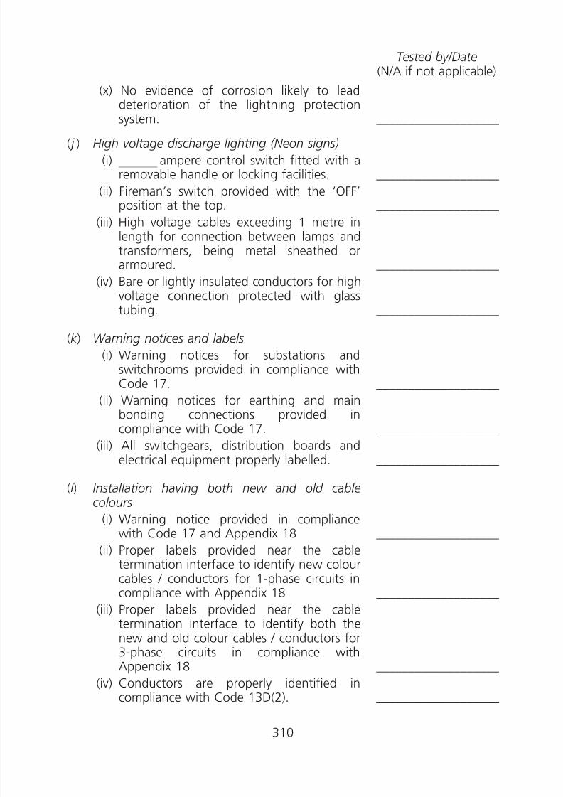
8/23/2019 Electricity Wiring
http://slidepdf.com/reader/full/electricity-wiring 310/337
___________________
___________________
___________________
___________________
___________________
___________________
___________________
___________________
___________________
___________________
___________________
______________________________________
(x) No evidence of corrosion likely to leaddeterioration of the lightning protectionsystem.
( j ) High voltage discharge lighting (Neon signs)
(i) ampere control switch fitted with a——————
removable handle or locking facilities.
(ii) Fireman’s switch provided with the ‘OFF’position at the top.
(iii) High voltage cables exceeding 1 metre inlength for connection between lamps andtransformers, being metal sheathed orarmoured.
(iv) Bare or lightly insulated conductors for highvoltage connection protected with glasstubing.
(k ) Warning notices and labels
(i) Warning notices for substations andswitchrooms provided in compliance with
Code 17.(ii) Warning notices for earthing and mainbonding connections provided incompliance with Code 17.
(iii) All switchgears, distribution boards andelectrical equipment properly labelled.
(l ) Installation having both new and old cablecolours
(i) Warning notice provided in compliancewith Code 17 and Appendix 18
(ii) Proper labels provided near the cabletermination interface to identify new colourcables / conductors for 1-phase circuits incompliance with Appendix 18
(iii) Proper labels provided near the cabletermination interface to identify both thenew and old colour cables / conductors for3-phase circuits in compliance withAppendix 18
(iv) Conductors are properly identified incompliance with Code 13D(2).
Tested by/Date(N/A if not applicable)
310

8/23/2019 Electricity Wiring
http://slidepdf.com/reader/full/electricity-wiring 311/337
___________________
___________________
___________________
___________________
___________________
___________________
______________________________________
___________________
___________________
___________________
___________________
___________________
___________________
___________________
Checklist No. 5—Items for H.V. Installation
(Note: For L.V. Installation/Equipment, please refer to other checklists inthis appendix)
Installation Address: __________________________________________
(a) Switchboard, circuit breakers
(i) No visible damage to impair safety.
(ii) Safe access and adequate clearance spaceprovided.
(iii) Work done properly recorded in log book.
(iv) Every circuit breaker provided with a legibleand durable identification label.
(v) An up-to-date schematic diagram displayed.
(vi) All accessible live parts screened withinsulating plate or earthed metal.
(vii) All exposed conductive parts effectively
earthed.(viii) Earthing system effectively connected.
(ix) Warning notice displayed at main bondingconnections.
(x) All protective devices are functionedproperly and correctly set.
(xi) Padlock facilities for shutters provided.
(xii) Maintenance test carried out accordingto relevant recognised standards andmanufacturers’ recommendation, whereappropriate, with test reports. (insulationresistance test, pressure test, ductor test, oildielectric strength test etc.)
(b) Main Cables
(i) No visible damage to impair safety.
(ii) Cables protected against mechanicaldamage and suitably supported.
(iii) All exposed metal parts including thearmour effectively earthed.
Tested by/Date(N/A if not applicable)
311

8/23/2019 Electricity Wiring
http://slidepdf.com/reader/full/electricity-wiring 312/337
___________________
___________________
___________________
___________________
___________________
___________________
___________________
___________________
___________________
___________________
___________________
(iv) Maintenance test carried out accordingto relevant recognised standards andmanufacturers’ recommendation, where
appropriate, with test reports. (insulationresistance test, pressure test etc.)
(c ) Transformers/Motors
(i) No visible damage to impair safety.
(ii) All accessible live parts screened withinsulating plate or earthed metal.
(iii) Proper ventilation provided to avoid
excessive temperature rise.
(iv) Maintenance test carried out accordingto relevant recognised standards andmanufacturers’ recommendation, whereappropriate, with test reports. (insulationresistance test, pressure test, oil dielectricstrength test etc.)
(d ) Earth
(i) A warning notice ‘SAFETY ELECTRICALCONNECTION—DO NOT REMOVE’ and ‘安全接地終端——切勿移去’ provided at allmain earthing and bonding connections.
(ii) Earthing conductors of adequate size.
(e) D.C. Battery System
(i) Condition of battery system.
(ii) Voltage of each battery cell measured.
( f ) Operation and Testing tools and equipment
(i) Proper operation tools and equipmentprovided for switching and isolation use.
(ii) Suitable self-test high voltage testerprovided for verifying equipment dead.
Tested by/Date(N/A if not applicable)
312

8/23/2019 Electricity Wiring
http://slidepdf.com/reader/full/electricity-wiring 313/337
Appendix 14
References
References may be made to the following publications for better applying and
understanding of the requirements of the CoP.IEC 60079 Electrical apparatus for explosive gas atmospheres
IEC 60085 Electrical insulation - Thermal classification
IEC 60127 Miniature fuses
IEC 60189 Low-frequency cables and wires with PVC insulationand PVC sheath
IEC 60227 Polyvinyl chloride insulated cables of rated voltages up
to and including 450/750 V
IEC 60228 Conductors for insulated cables
IEC 60238 Edison screw lampholders
IEC 60245 Rubber insulated cables of rated voltages up to andincluding 450/750 V
IEC 60269 Low-voltage fuse
IEC 60309 Plugs, socket-outlets and couplers for industrialpurposes
IEC 60364 Low-voltage electrical installations / Electricalinstallations of buildings
IEC 60423 Conduit systems for cable management - Outsidediameters of conduits for electrical installations andthreads for conduits and fittings
IEC 60439 Low-voltage switchgear and controlgear assemblies
IEC 60529 Degree of protection provided by enclosures (IP Code)
IEC 60617 Graphical symbols for diagrams
IEC 60669 Switches for household and similar fixed electricalinstallations
IEC 60702 Mineral insulated cables and their terminations with arated voltage not exceeding 750 V
IEC 60755 General requirements for residual current operatedprotective devices
IEC 60898 Electrical accessories - Circuit-breakers for overcurrentprotection for household and similar installations
313
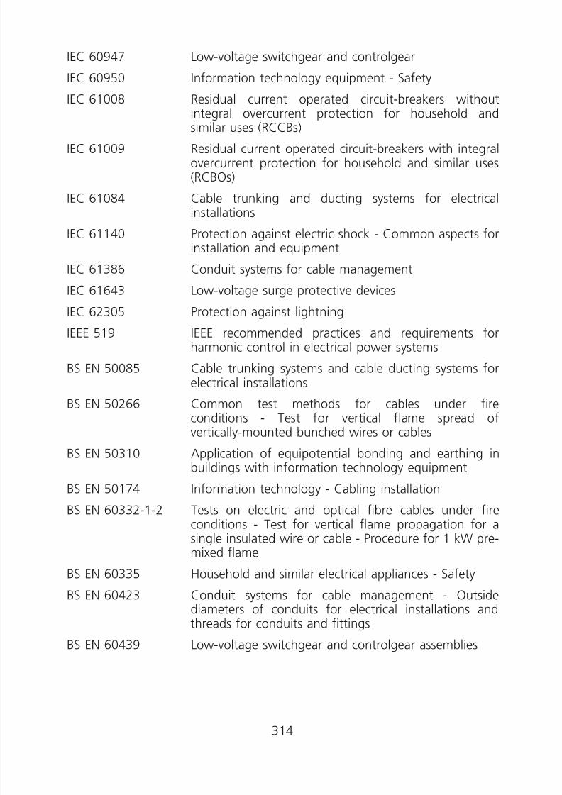
8/23/2019 Electricity Wiring
http://slidepdf.com/reader/full/electricity-wiring 314/337
IEC 60947 Low-voltage switchgear and controlgear
IEC 60950 Information technology equipment - Safety
IEC 61008 Residual current operated circuit-breakers withoutintegral overcurrent protection for household and
similar uses (RCCBs)IEC 61009 Residual current operated circuit-breakers with integral
overcurrent protection for household and similar uses(RCBOs)
IEC 61084 Cable trunking and ducting systems for electricalinstallations
IEC 61140 Protection against electric shock - Common aspects forinstallation and equipment
IEC 61386 Conduit systems for cable management
IEC 61643 Low-voltage surge protective devices
IEC 62305 Protection against lightning
IEEE 519 IEEE recommended practices and requirements forharmonic control in electrical power systems
BS EN 50085 Cable trunking systems and cable ducting systems for
electrical installationsBS EN 50266 Common test methods for cables under fire
conditions - Test for vertical flame spread ofvertically-mounted bunched wires or cables
BS EN 50310 Application of equipotential bonding and earthing inbuildings with information technology equipment
BS EN 50174 Information technology - Cabling installation
BS EN 60332-1-2 Tests on electric and optical fibre cables under fireconditions - Test for vertical flame propagation for asingle insulated wire or cable - Procedure for 1 kW premixed flame
BS EN 60335 Household and similar electrical appliances - Safety
BS EN 60423 Conduit systems for cable management - Outsidediameters of conduits for electrical installations andthreads for conduits and fittings
BS EN 60439 Low-voltage switchgear and controlgear assemblies
314
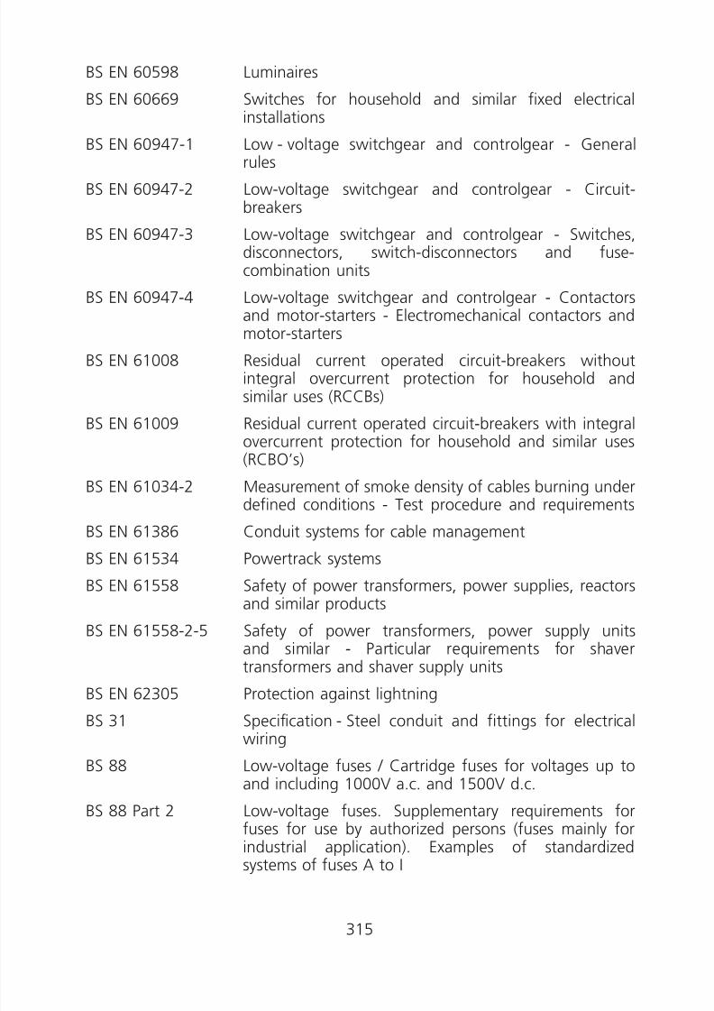
8/23/2019 Electricity Wiring
http://slidepdf.com/reader/full/electricity-wiring 315/337
BS EN 60598 Luminaires
BS EN 60669 Switches for household and similar fixed electricalinstallations
BS EN 60947-1 Low - voltage switchgear and controlgear - General
rulesBS EN 60947-2 Low-voltage switchgear and controlgear - Circuit-
breakers
BS EN 60947-3 Low-voltage switchgear and controlgear - Switches,disconnectors, switch-disconnectors and fuse-combination units
BS EN 60947-4 Low-voltage switchgear and controlgear - Contactorsand motor-starters - Electromechanical contactors and
motor-starters
BS EN 61008 Residual current operated circuit-breakers withoutintegral overcurrent protection for household andsimilar uses (RCCBs)
BS EN 61009 Residual current operated circuit-breakers with integralovercurrent protection for household and similar uses(RCBO’s)
BS EN 61034-2 Measurement of smoke density of cables burning underdefined conditions - Test procedure and requirements
BS EN 61386 Conduit systems for cable management
BS EN 61534 Powertrack systems
BS EN 61558 Safety of power transformers, power supplies, reactorsand similar products
BS EN 61558-2-5 Safety of power transformers, power supply units
and similar - Particular requirements for shavertransformers and shaver supply units
BS EN 62305 Protection against lightning
BS 31 Specification - Steel conduit and fittings for electricalwiring
BS 88 Low-voltage fuses / Cartridge fuses for voltages up toand including 1000V a.c. and 1500V d.c.
BS 88 Part 2 Low-voltage fuses. Supplementary requirements forfuses for use by authorized persons (fuses mainly forindustrial application). Examples of standardizedsystems of fuses A to I
315

8/23/2019 Electricity Wiring
http://slidepdf.com/reader/full/electricity-wiring 316/337
BS 88 Part 6 Cartridge fuses for voltages up to and including 1000Va.c. and 1500V d.c. Specification of supplementaryrequirements for fuses of compact dimensions for usein 240/415V a.c. industrial and commercial electricalinstallations
BS 196 Specification for protected-type non-reversible plugs,socket-outlets, cable-couplers and appliance-couplerswith earthing contacts for single-phase a.c. circuits upto 250 volts
BS 476 Part 20 Fire tests on building materials and structures. Methodfor determination of the fire resistance of elements ofconstruction (general principles)
BS 546 Specification-Two-pole and earthing-pin plugs, socket-
outlets and socket-outlet adaptors
BS 1361 Specification for cartridge fuses for a.c. circuits indomestic and similar premises
BS 1363 13 A plugs, socket-outlets, adaptors and connectionunits
BS 2782 Part 1 Methods of testing plastics-Thermal properties
BS 3036 Specification - Semi-enclosed electric fuses (ratings up
to 100 amperes and 240 volts to earth)
BS 3676 Switches for household and similar fixed electricalinstallations
BS 4444 Guide to electrical earth monitoring and protectiveconductor proving
BS 4568 Specification for steel conduit and fittings with metricthreads of ISO form for electrical installations
BS 4607 Non-metallic conduits and fittings for electricalinstallations
BS 4662 Boxes for flush mounting of electrical accessories.Requirements and test methods and dimensions
BS 4678 Cable trunking
BS 5266 Emergency lighting
BS 5467 Electric cables. Thermosetting insulated, armoured
cables for voltages of 600/1000 V and 1900/3300 VBS 5839 Fire detection and fire alarm systems for buildings
316
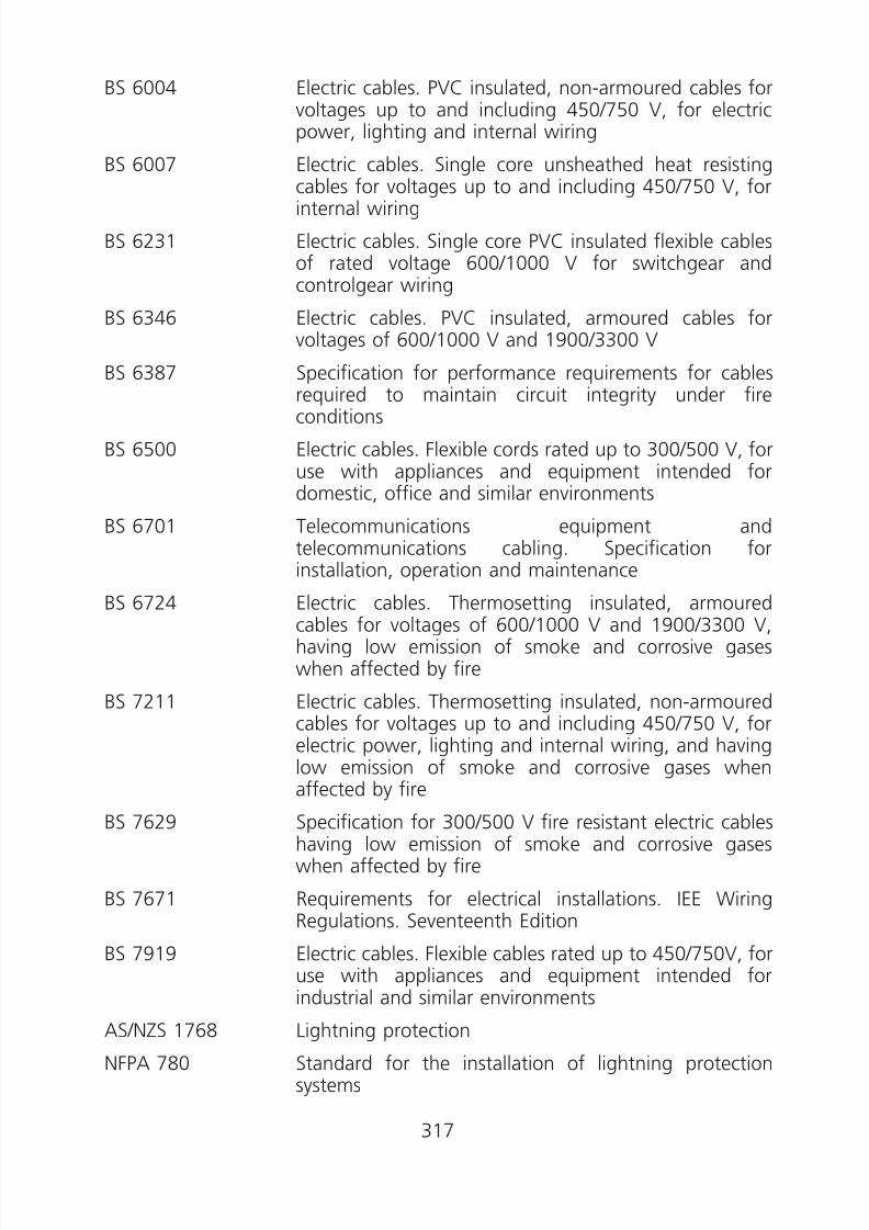
8/23/2019 Electricity Wiring
http://slidepdf.com/reader/full/electricity-wiring 317/337
BS 6004 Electric cables. PVC insulated, non-armoured cables forvoltages up to and including 450/750 V, for electricpower, lighting and internal wiring
BS 6007 Electric cables. Single core unsheathed heat resistingcables for voltages up to and including 450/750 V, forinternal wiring
BS 6231 Electric cables. Single core PVC insulated flexible cablesof rated voltage 600/1000 V for switchgear andcontrolgear wiring
BS 6346 Electric cables. PVC insulated, armoured cables forvoltages of 600/1000 V and 1900/3300 V
BS 6387 Specification for performance requirements for cables
required to maintain circuit integrity under fireconditions
BS 6500 Electric cables. Flexible cords rated up to 300/500 V, foruse with appliances and equipment intended fordomestic, office and similar environments
BS 6701 Telecommunications equipment andtelecommunications cabling. Specification forinstallation, operation and maintenance
BS 6724 Electric cables. Thermosetting insulated, armouredcables for voltages of 600/1000 V and 1900/3300 V,having low emission of smoke and corrosive gaseswhen affected by fire
BS 7211 Electric cables. Thermosetting insulated, non-armouredcables for voltages up to and including 450/750 V, forelectric power, lighting and internal wiring, and havinglow emission of smoke and corrosive gases when
affected by fireBS 7629 Specification for 300/500 V fire resistant electric cables
having low emission of smoke and corrosive gaseswhen affected by fire
BS 7671 Requirements for electrical installations. IEE WiringRegulations. Seventeenth Edition
BS 7919 Electric cables. Flexible cables rated up to 450/750V, foruse with appliances and equipment intended for
industrial and similar environmentsAS/NZS 1768 Lightning protection
NFPA 780 Standard for the installation of lightning protectionsystems
317
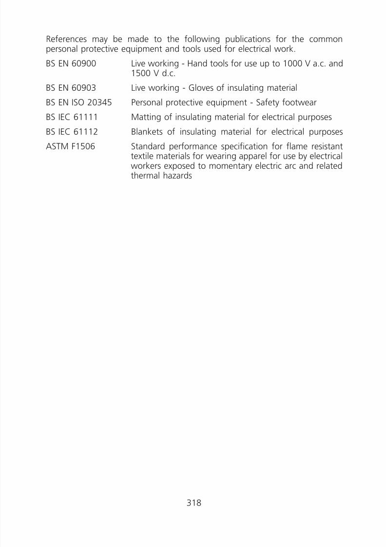
8/23/2019 Electricity Wiring
http://slidepdf.com/reader/full/electricity-wiring 318/337
References may be made to the following publications for the commonpersonal protective equipment and tools used for electrical work.
BS EN 60900 Live working - Hand tools for use up to 1000 V a.c. and1500 V d.c.
BS EN 60903 Live working - Gloves of insulating materialBS EN ISO 20345 Personal protective equipment - Safety footwear
BS IEC 61111 Matting of insulating material for electrical purposes
BS IEC 61112 Blankets of insulating material for electrical purposes
ASTM F1506 Standard performance specification for flame resistanttextile materials for wearing apparel for use by electricalworkers exposed to momentary electric arc and related
thermal hazards
318
8/23/2019 Electricity Wiring
http://slidepdf.com/reader/full/electricity-wiring 319/337
Appendix 15
Safety for Live Work
(A) Conditions and Safety Precautions for Live Work
1. Live work should not be performed unless:
(i) it is necessary in the interests of safety, whether or not electricalsafety, for the work to be performed while the electrical equipmentis energised (e.g. work on hospital equipment); or
(ii) a supply of electricity is essential for the proper performance of theelectrical measurement (e.g. testing and fault finding); or
(iii) there is no reasonable alternative to perform the electrical work bylive work (e.g. widespread outages of a building would occur if livework is not allowed); or
(iv) it is justified and approved by the registered electrical worker,registered electrical contractor and owner of the installation (e.g.serious public inconvenience would arise from isolating the circuits).
2. Where live work is unavoidable, adequate precautions should be taken toavoid danger for work involving the handling of energised parts orworking within touchable distance, direct or indirect, of energised partsat low voltage. The following precautions are to be taken:
(i) work on energised low voltage electrical equipment should be doneonly by registered electrical workers who are by virtue of knowledgeand training competent to be allowed to carry out live work;
(ii) prior risk assessment should be carried out by the registeredelectrical contractor, registered electrical worker or a registeredsafety officer on the performance of the live work (sample provided);
(iii) personal protective equipment (including insulating gloves, safetyshoes and insulating mat) and testing equipment appropriate to the
performance of the live work should be properly used by the personperforming the electrical work;
(iv) screen or other means to avoid danger from inadvertent contactwith energised conductors should be provided;
(v) fixing of warning notices for repair, barriers and screens;
(vi) the duration and the extent of the live work should be minimized asfar as practicable; and
(vii) the isolation point of the electricity supply for the subject electricalequipment has been clearly identified.
319

8/23/2019 Electricity Wiring
http://slidepdf.com/reader/full/electricity-wiring 320/337
320

8/23/2019 Electricity Wiring
http://slidepdf.com/reader/full/electricity-wiring 321/337
APPENDIX 16
(SAMPLE)
工程許可證 PERMIT-TO-WORK
組/處 許可證號碼 ........................................... SECTION/OFFICE Permit No.................................................
部門 地點 ........................................... DEPARTMENT Location ...................................................
第 1 部 PART 1.
本人謹此聲明,下述電力器具已經根據電力(線路)規例工作守則第 4 條有關對高壓和低壓電力
裝置施工的安全規定,截斷電源、隔離和接地,可以安全進行工程。本人已提醒負責工程主管注意該份安全規定。 I hereby declare that it is safe to work on the following electrical equipment, which has beenisolated, made dead, and earthed in accordance with the safety precautions for work on highvoltage and low voltage electrical apparatus in Code 4 of the Code of Practice. I have drawn theattention of the person in charge of the work to these precautions.
本人已經向負責工程主管,直接指出該電力器具、說明工程範圍以及講解安全措施。 I have physically identified the electrical equipment, explained the extent of the work anddemonstrated the safety arrangements to the Person who is to be in charge of the work.
進行工程的電力器具 ELECTRICAL EQUIPMENT TO BE WORKED ON ...............................................................................
電力器具的地點 LOCATION OF ELECTRICAL EQUIPMENT ........................................................................................
要進行的工程詳情 DETAILS OF WORK TO BE DONE....................................................................................................
電力器具被隔離的確實位置 EXACT POINTS WHERE ELECTRICAL EQUIPMENT IS ISOLATED.......................................................
電力器具接地的確實位置 EXACT POINTS WHERE ELECTRICAL EQUIPMENT IS EARTHED .......................................................
已鎖上安全鎖的位置 SAFETY LOCKS APPLIED AT ...........................................................................................................
警告告示和危險告示豎立位置 CAUTION NOTICES AND DANGER NOTICES HAVE BEEN POSTED AT ............................................
特別指示或安全措施 SPECIAL INSTRUCTIONS, OR SAFETY MEASURES ...........................................................................
簽署 (負責人員)
Signed ................................................................ (Responsible Person)
姓名 聯絡電話號碼 Name ............................................................... Contact Tel. No. .................................................
時間 (上午/下午 *) 時 分 日期 Time (a.m./p.m.*) .............. hours ................ minutes Date..............................................
321

8/23/2019 Electricity Wiring
http://slidepdf.com/reader/full/electricity-wiring 322/337
第 2 部 PART 2.
本人確認收到工程許可證和裝備安全鎖匙箱的鎖匙。本人已閱讀過此工程許可證的內容,並證實該電力器具已按需要在上述地點切斷電源及隔離。有關的安全設備和接地線均不會移走,直至此許可證被撤銷並得到負責人員的准許為止。 I acknowledge receipt of this permit-to-work and of the key for the equipment safety key box. Ihave read the content of this permit-to-work and I certified that where applicable the electricalequipment is switched out and isolated on these premises. Safety devices and earths will not beremoved until this permit-to-work has been cancelled and permission has been obtained from theResponsible Person.
本人謹此聲明,本人接納此工程許可證上所述在該電力器具進行工程的責任,而本人及本人轄下人員,均不會在其他電力器具進行工程。 I declare that I accept the responsibility for carrying out work on the electrical equipmentdescribed on this permit-to-work and that no attempt will be made by me or by the personsunder my control to carry out work on other electrical equipment.
在第 1 部所述的工程進行期間,本人會保留此工程許可證,並會在工程完成或停止後,將許可證交還負責人員。 I will retain this permit-to-work while the work described in Part 1 is in progress and will return itto the Responsible Person when the work is completed or stopped.
簽署 (工程主管)
Signed ................................................................ (Person in-charge)
姓名 聯絡電話號碼 Name ............................................................... Contact Tel. No. .................................................
時間 (上午/下午 *) 時 分 日期 Time (a.m./p.m.*) .............. hours ................ minutes Date..............................................
受僱於 In the employ of ............................................................................................................................
此許可證在第 1 及第 2 部簽署後才生效 THIS PERMIT IS NOT VALID UNTIL PARTS 1 AND 2 HAVE BEEN SIGNED
第 3 部 PART 3.
本人謹此聲明,此工程許可證第 1 部所述工程已圓滿完成/停止 * ,本人轄下所有人員已經撤離,並受到警告:在上述電力器具進行工程已不安全。所有工具及臨時接線均已撤走。 I hereby declare that Work described in Part 1 of this permit-to-work has been satisfactorilycompleted/stopped*, and all persons under my charge have been withdrawn and warned thatthe above electrical equipment is no longer safe to work on. All tools and temporary connectionshave been removed.
簽署 (工程主管)Signed ................................................................ (Person in-charge)
時間 (上午/下午 *) 時 分 日期 Time (a.m./p.m.*) .............. hours ................ minutes Date..............................................
322

8/23/2019 Electricity Wiring
http://slidepdf.com/reader/full/electricity-wiring 323/337
第 4 部 PART 4.
本人謹此聲明,此工程許可證第 1 部所述工程已圓滿完成/停止 * ,此工程許可證現予以撤銷。工程許可證正本已交還本人並已銷毀。 I hereby declare that the work described in Part 1 of this permit-to-work has been satisfactorily
completed/stopped* and that this permit-to-work is cancelled. The original permit-to-work hasbeen returned to me and destroyed.
簽署 Signed ................................................................
負責人員 Responsible person
時間 (上午/下午 *) 時 分 日期 Time (a.m./p.m.*) .............. hours ................ minutes Date..............................................
* 將不適用的刪除 Delete as appropriate.
323
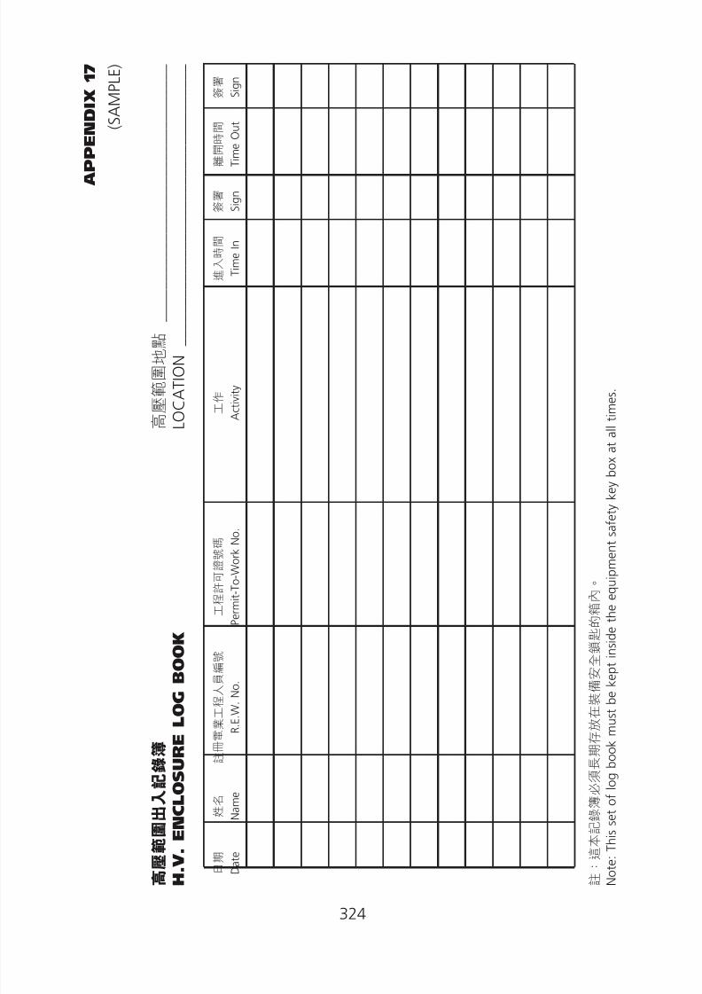
8/23/2019 Electricity Wiring
http://slidepdf.com/reader/full/electricity-wiring 324/337
324
A P P E N D I X
1 7
( S A M P L E )
高 壓 範 圍 出 入 記 錄 簿
高 壓 範 圍 地 點
________________________________
H . V . E N C L O S U R E
L O G
B O O K
L O C A T I O N
___________________________________
日 期
D a
t e
姓 名
N a m e
註 冊 電 業 工 程 人 員 編 號
R . E . W .
N o .
工 程 許 可 證 號 碼
P e r m
i t - T o - W o r k
N o .
工 作
A c t i v i t y
進 入 時 間
T i m e
I n
簽 署
S i g n
離
開 時 間
T i m e
O u
t
簽 署
S i g n
註 : 這 本 記 錄 簿
必 須 長 期 存 放 在 裝 備 安 全 鎖
匙 的 箱 內 。
N o
t e :
T h i s s e t o
f l o g
b o o
k m u s t
b e
k e p
t i n s
i d e
t h e e q u
i p m e n
t s a
f e t y k e y
b o x a
t a
l l t i m e s .

8/23/2019 Electricity Wiring
http://slidepdf.com/reader/full/electricity-wiring 325/337
Appendix 18
New Cable Colour Code for Fixed Electrical InstallationsInstallation Guidelines
(1) Introduction
With effect from 1 July 2007, colour for identification of conductors in fixedelectrical installations is changed as shown in Table 13(2) of the CoP.
The change is applicable to all new electrical installations as well as addition &alteration to existing electrical installations. Existing installations with cablesadopting the old cable colour code are not affected.
A Working Group on the Review of Cable Colour Code in Hong Kongcomprising members from the trade and industry was established in year2003 to study the cable colour change issue in Hong Kong. In mid 2004, theWorking Group proposed to adopt the new cable colour code in Hong Kong.The change was then endorsed by the Electrical Safety Advisory Committee inSeptember 2004.
The new cable colour code complies with the requirements of relevantnational and international standards (such as IEC 60446, EN 60446, BS EN
60446 and BS 7671) and has been adopted by the majority of the westerncountries (e.g. UK, France, Germany, Spain, Netherlands, Portugal etc.).
(2) Implementation
The new colour code may be used for those electrical installation workscommencing on-site on or after 1 July 2007. For installation works
commencing on-site from 1 July 2007 to 30 June 2009 (i.e. the 2-year graceperiod), either the new or the old colour code, but NOT both, can be used.For installation works commencing on-site on or after 1 July 2009, only thenew colour code should be used.
Figure A18(1) - Implementation Schedule
325

8/23/2019 Electricity Wiring
http://slidepdf.com/reader/full/electricity-wiring 326/337
(3) Precautions
In the new colour code, the black core is changed from neutral to phase andthe blue core from phase to neutral (see Table 13(2)). Wrong connection ofthese cores will lead to increased risk, leading to possible electrical accidents
and short circuiting, in particular during the transition period. To ensureelectrical safety, it is recommended not to conduct, whenever practicable,works on “LIVE” installations at any cable colour change interfaces. Whereserious inconvenience would arise from isolating electrical circuits for works atthe cable colour change interfaces, adequate safety precautions should betaken to avoid danger from “LIVE” working conditions (see Code 4 of theCoP for details).
(4) Installation Guides - New Installation
The old cable colour code, i.e. red, yellow and blue for phase conductors andblack for the neutral conductor, are to be replaced by the new one, i.e.brown, black and grey for phase conductors and blue for the neutralconductor, as specified in Table 13(2). Circuits for new installations should bewired in new colour coded cables (see examples in Figures A18(2a) and (2b)).
For a single phase installation, only the brown colour should be used toidentify a phase conductor, irrespective of whether it is connected to the L1,L2 or L3 phase. For a room / flat /unit taking single phase electricity supplyfrom a multi-phase power supply source, only brown (phase) and blue(neutral) coloured cables should be used.
Figure A18(2a) - New coloured wiring cables in a single phase distribution board
326

8/23/2019 Electricity Wiring
http://slidepdf.com/reader/full/electricity-wiring 327/337
Figure A18(2b) - New coloured wiring in a 3-phase distribution board
(5) Installation Guides - Extensions, Alterations or Repair to
an Existing Installation
5.1 Warning Notice
Where cables in new colour code are installed in an existing installation withold colour coded cables, a yellow warning notice in both English and Chinese(see Figure A18(3)) should be displayed at or close to the nearest upstreamdistribution board (e.g. main switchboard, sub-main distribution board orconsumer unit) of the affected installation. The warning notice should comply
with the requirements specified in Code 17F of the CoP.
Figure A18(3) - Warning Noice
327
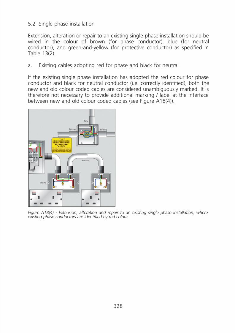
8/23/2019 Electricity Wiring
http://slidepdf.com/reader/full/electricity-wiring 328/337
5.2 Single-phase installation
Extension, alteration or repair to an existing single-phase installation should bewired in the colour of brown (for phase conductor), blue (for neutralconductor), and green-and-yellow (for protective conductor) as specified in
Table 13(2).
a. Existing cables adopting red for phase and black for neutral
If the existing single phase installation has adopted the red colour for phaseconductor and black for neutral conductor (i.e. correctly identified), both thenew and old colour coded cables are considered unambiguously marked. It istherefore not necessary to provide additional marking / label at the interfacebetween new and old colour coded cables (see Figure A18(4)).
Figure A18(4) - Extension, alteration and repair to an existing single phase installation, where
existing phase conductors are identified by red colour
328
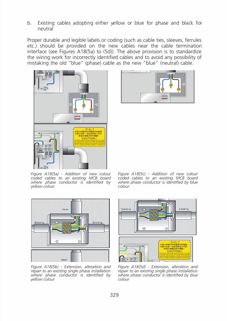
8/23/2019 Electricity Wiring
http://slidepdf.com/reader/full/electricity-wiring 329/337
b. Existing cables adopting either yellow or blue for phase and black forneutral
Proper durable and legible labels or coding (such as cable ties, sleeves, ferrulesetc.) should be provided on the new cables near the cable termination
interface (see Figures A18(5a) to (5d)). The above provision is to standardizethe wiring work for incorrectly identified cables and to avoid any possibility ofmistaking the old “blue” (phase) cable as the new “blue” (neutral) cable.
Figure A18(5a) - Addition of new colour coded cables to an existing MCB board where phase conductor is identified by yellow colour
Figure A18(5c) - Addition of new colour coded cables to an existing MCB board where phase conductor is identified by bluecolour
Figure A18(5b) - Extension, alteration and repair to an existing single phase installationwhere phase conductor is identified by yellow colour
Figure A18(5d) - Extension, alteration and repair to an existing single phase installationwhere phase conductor is identified by bluecolour
329

8/23/2019 Electricity Wiring
http://slidepdf.com/reader/full/electricity-wiring 330/337
5.3 Three-phase installation
Extension, alteration or repair to an existing 3-phase installation should bewired in the new colour code of brown/ black/ grey/ blue/ (green-and-yellow)as specified in Table 13(2).
At the wiring interface, both the new and old phase and neutral conductorsshould be fitted with proper, durable and legible identification marked in L1,L2, L3 and N (Figure A18(6)).
For the interface between new and old colour coded cables at a busbarchamber for an existing three-phase installation, an acceptable means ofidentification is illustrated in Figure A18(7).
Figure A18(6) - Extensions, alterations or repairs to an existing three-phase installation
Figure A18(7) - Interface between new and old colour coded cables at a busbar chamber for anexisting three-phase installation
330
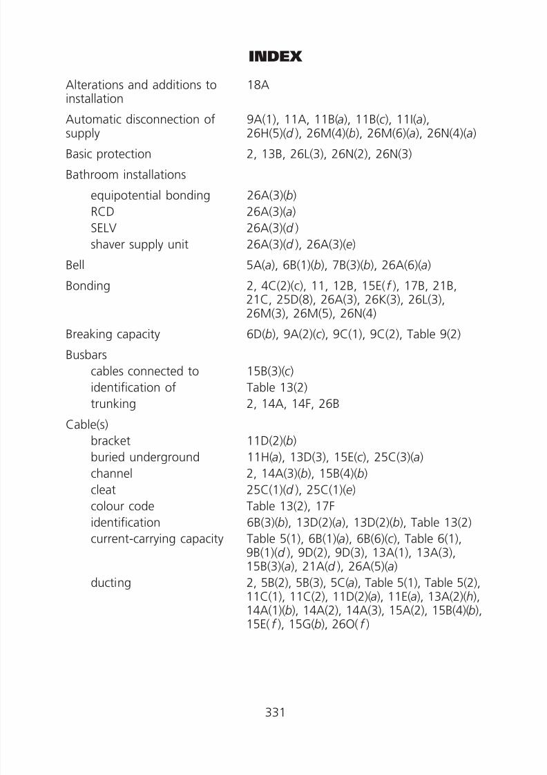
8/23/2019 Electricity Wiring
http://slidepdf.com/reader/full/electricity-wiring 331/337
INDEX
Alterations and additions to 18Ainstallation
Automatic disconnection of 9A(1), 11A, 11B(a), 11B(c ), 11I(a),supply 26H(5)(d ), 26M(4)(b), 26M(6)(a), 26N(4)(a)
Basic protection 2, 13B, 26L(3), 26N(2), 26N(3)
Bathroom installations
equipotential bonding 26A(3)(b)
RCD 26A(3)(a)
SELV 26A(3)(d )
shaver supply unit 26A(3)(d ), 26A(3)(e)
Bell 5A(a), 6B(1)(b), 7B(3)(b), 26A(6)(a)
Bonding 2, 4C(2)(c), 11, 12B, 15E( f ), 17B, 21B,21C, 25D(8), 26A(3), 26K(3), 26L(3),26M(3), 26M(5), 26N(4)
Breaking capacity 6D(b), 9A(2)(c ), 9C(1), 9C(2), Table 9(2)
Busbars
cables connected to 15B(3)(c )identification of Table 13(2)
trunking 2, 14A, 14F, 26B
Cable(s)
bracket 11D(2)(b)
buried underground 11H(a), 13D(3), 15E(c ), 25C(3)(a)
channel 2, 14A(3)(b), 15B(4)(b)
cleat 25C(1)(d ), 25C(1)(e)
colour code Table 13(2), 17Fidentification 6B(3)(b), 13D(2)(a), 13D(2)(b), Table 13(2)
current-carrying capacity Table 5(1), 6B(1)(a), 6B(6)(c ), Table 6(1),9B(1)(d ), 9D(2), 9D(3), 13A(1), 13A(3),15B(3)(a), 21A(d ), 26A(5)(a)
ducting 2, 5B(2), 5B(3), 5C(a), Table 5(1), Table 5(2),11C(1), 11C(2), 11D(2)(a), 11E(a), 13A(2)(h),14A(1)(b), 14A(2), 14A(3), 15A(2), 15B(4)(b),
15E( f ), 15G(b), 26O( f )
331

8/23/2019 Electricity Wiring
http://slidepdf.com/reader/full/electricity-wiring 332/337
enclosure
in conduit and trunking
in parallel
installed in wallinstalled under floors orabove ceiling
joints
method of installation
sealing
segregation supports
trunking
Circuit arrangement
Circuit breaker
breaking capacity
definition
linked
Circuit protective conductor
Circuits
category
division of installation
2, 4B(1)(c ), 4C(2)(a), 4D(1)(b), 4E( f ),4F(1)(a), 5B(2), 5B(3), 5B(4), 5C(c ), Table 5(1), Table 5(2), 6C(b), 9E(a),11C(1)(b), 11C(2)(a), 11C(2)(d ), 11D(2)(a),11D(3)(a), 11D(3)(d ), 14A(1), 14A(2),
14E(1), 15A(2), 15B(1)(b), 15B(4), 15C( f ),15E(e), 21A( g), 26H(4)(c ), 26K(3)(e), 26O( f )
2, 5B(2)(b), 5B(3)(b), 5C(a), Table 5(1),Table 5(2), 11C(1)(b), 11D(2)(a), 11D(3)(b),Table 11(1), 13A(2)(h), 14A, 14B, 14D,14E(2), Table 14(2), Table 14(3), 15E(e),15E( f ), 25A(1)(e), 25A(1)( g), 25B(1)(c ),25C(1)( f ), 25C(2)(c ), 26O( f )
9B(1)(e), 12C(3)(b), 26O( f )(iv)
15E( f ), 25C(1)(a) 25C(1)( g)15E(e), 25C(1)( f )
4B(1)(c ), 9B(1)(a), 11F(a), 13C, 15A(2)(b),16C, 25D(1), 25D(3), 25D(5)(a), 25D(7)(b)
13A(2)(d ), 21B(10)(b)
14A(3), 15A(2)(b), 15A(2)(e), 25A(1)(c ),25C(1)( g), 25C(2)(b), 25D(7)(c )
515E(e), 15F, 15G(d ), 15G(e), 16B, 16H(2),25C(1)(b), 25C(1)( f ), 25C(4)(d ), Table 25(3), 26H(4)(d ), 26K(3)(b)
2, 5C(a), 11C(2)(e), 14E(2), 15B(4), 25B,25C(1)( f )
6, 6C, 6F(2)(i ), 6G(2)( f ), 26A(2)(a)
6D(b), 9C(1), 9C(2)(b), Table 9(2)
2
8A(1)(a), 9E( g), 10A, 10B, 26A(5)(a)
2, 6C(b), 11C(1)(a), 11D(1), 11D(3), 11G(a),14B(2)(c ), 25A(1)(a), 25D(6), 25D(7),26A(5)(c ), 26O( f )
3B, 5A, 5B, 5C, Table 5(1), Table 5(2),13A(2)(h), 25C(3)(a), 26G
6A
332

8/23/2019 Electricity Wiring
http://slidepdf.com/reader/full/electricity-wiring 333/337
final
isolation
Class II equipment or insulation
Concealed cables
Conductive parts
exposed conductive parts
4G(3), 6B(1)(b), 6B(4), 6C(c ), 6D, 6E(2),6E(4), 6F(1), 6F(2), 6G(2), 6H(2),Table 6(1), 7B(3), 7B(4), Table 7(1),11D(3)(d ), 21B(2)(a), 21B(3), 25A(1)( g),25C(2)( f ), 25D(1), 26A(1), 26A(2)(b),
26A(3)(e), 26A(4), 26A(5)(d ), 26O(e),26O( f )
4C(2)(c ), 4E(a), 5A(b), 6B(2), 8A(1), 8A, 8B,21A(h), 26H(2)
26M(5)(d ), 26N(4)
15E( f )
2, 4C(2)(c ), 11A, 11B(a), 11D, 11F(b),11F(d ), 12B(2), 14D(2), 21B(6)( f ), 21C(b),25D(5)(a), 25D(8)(a), 26A(3)(a), 26A(3)(b),26E, 26H(7), 26M(3), 26O( f )
extraneous conductive parts 2, 4C(2)(c ), 11B(a), 11B(b), 11E(a), 11F,
Conduit and conduit system
Conduit box/junction box
Construction site installations
Current-carrying capacity
cables and conductors
neutral
parallel conductors
Diagrams, provision of
Discharge lighting
Disconnection time
21B(4), 25D(5)(a), 25D(8)(a), 26A(3)(a),26A(3)(b), 26M(3), 26N(4)(c )
2, 5B(2)(b), 5B(3)(b), 5C(a), Table 5(1),Table 5(2), 11C(1), 11C(2)(a), 11D(2),
11D(3), Table 11(1), 13A(2), 14A, 14B,14D, 14E, 14F, Table 14(2), Table 14(3),15A(2), 15D(3), 15E, 15G(b), 25A, 25B,25C(1), 25D(8), Table 25(1), 26A(3)( f ),26M(5)(b), 26O( f )
14A(1)(b), 14B(1)(c ), 14B(2)(b), 14D(1)(c ),14D(2)(b), 25A(1)(b), 25A(3), 25D(1),25D(2), 25D(8)(b), 25D(8)(c ), 26M(5)(b)
21E(4)(c ), 26K(2)(b), 26K(3)
Table 5(1), 6B(1)(a), Table 6(1), 9B(1),9D(2), 9D(3), 13A(1), 13A(3), 15B(3)(a),21A(d ), 26A(5)(a)
6B(1)(a), 6B(6), 26A(5)(a), 26B(3)(a), 26F(b),26H(1)(d )
9B(1)(e), 12C(3)(b), 26O( f )
6A(b), 8A, 21A(m), 22C(a)
7B(3)(b), 8A(2)(b), 8B(2)(d ), 20A(3)(b), 26H
11B(b)
333

8/23/2019 Electricity Wiring
http://slidepdf.com/reader/full/electricity-wiring 334/337
Double insulation
Duct
Earth fault currentEarth-free local equipotentialbonding
Earthed equipotential bonding
Electrical equipment, safetyrequirement
Emergency switch
Equipotential bonding
Equipotential zone
Exhibitions, shows and stands
Explosive atmosphere
Exposed conductive parts
Extraneous conductive parts
bathroom
bonding of
swimming pools
Fault
Fault protectionFELV
Festive lighting
5A(b), 11D(1), 11D(2)
2, 5B(2)(b), 5B(3)(b), 5C(a), Table 5(1),13A(2)(h), 14A(3), 15A(2)(h), 15B(4)(b),15E(c )
2, 11, 11J, 12B(3), 18A(b)26L(3)(b)
11A
4, 15D, Table 15(4)
8A(3), 8A(6), 8B(1)(c ), 8B(4), 26H(3)
2, 4C(2)(c ), 11A, 11B(b), 11C, 11E, 11F,21B(2)(a), 21B(4), 25D(8)(a), 26A(3),26L(3)(b), 26M(3), 26M(5)(d ), 26N(4),26Q(3)(b)
11B(b), 11E, 11F(a)
26Q
4B(2)(b), 15D(1)(a), 15D(2)(c )
2, 4C(2)(c ), 11A, 11B, 11D, 11F, 12B(2),14D(2)(b), 21B(6)( f ), 21C(b), 25D(5)(a),25D(8)(a), 26A(3), 26E, 26H(7), 26M(3),26N(4)
11B(b), 26A(3)
4C(2)(c ), 11E(a), 11F, 21B(4), 25D(8)(a),26(3)(b), 26M(3), 26N(4)(c )
26M(3)
2, 6B(1), 8A(1), 9A(1), 9A(3), 9B(2), 9C(1),9C(2), 9D(3), Table 9(2), Table 9(3), 11A,11B, 11I, 11J, Table 11(5), Table 11(8),Table 11(9), Table 11(10), Table 11(11),Table 11(12), Table 11(13), Table 11(14),13A(1), 18A(b), 21B(2), 21B(8), 21B(9),21B(10), 26A(3)(a), 26H(5), 26K
2, 11A, 11J(2)(c ), 21A(o), 26N(2), 26N(4)26N(2)
26Q
334

8/23/2019 Electricity Wiring
http://slidepdf.com/reader/full/electricity-wiring 335/337
Final circuits
arrangement
ring
separation of
joint
Fire barriers
Fuse
Generator
Harmonic current
High voltage discharge lighting
Inspection and testing
Instantaneous water heater
Insulation
Isolationmotor circuit
neutral conductor
plug and socket outlet
remote devices
requirement
Jointscable and conductor
conduit system
earthing system
4G(3), 6B(1)(b), 6C, 6D, 6E, 6F, 6G, 6H,Table 6(1), 7B(3), 7B(4), Table 7(1),26A(4)(a)
6C, 6E, 6F, Table 6(1), 11D(3)(d ), 21B(4)
6B(4)
25D(1)
14A(3), 21A( f )
2, 4D(1)(a), 4E(d ), 6D(b), 6E(2), 6E(4), 6F,6G, Table 6(1), 8B(2)(b), 9A(2), 9B(1)(d ),9E, Table 9(2), 10A(b), 10B, Table 11(3),Table 11(4), Table 11(8), Table 11(9), Table 11(11), Table 11(12), 13A(4)(d ),21A( j ), 21B(5)(c ), 21B(6)(a), 21B(9)(b),21B(10)(d ), 26A(4)(a), 26A(5), 26A(6)(e)
8A(1)(d ), 10C, 26K(3)( f ), 26N(4)( f ),26Q(3)( f )
4D(3), 6B(6)(c ), 7B(3)(b), 26H(1)(b)
8A(2)(b), 8B(4)(d ), 20A(3)(b), 26H
4D(3), 22D(1), 22D, 26K(2)(b), 26P(3)
Table 7(1), 26A(5)
4C(1)(c ), 9B(1)(a), Table 9(1), 13A(3),13A(4)(e), 13B(1), 14E(2)(d ), 15A(2),15B(2), 15B(3), 15B(5)(b), 15G(a), Table 15(1), Table 15(2), 21A( g), 21B(2)(a),21B(5), 21B(10)(a), 21E(2), Table 21(1),25D(3)(b), 26H(5)(a), 26L(5)(c ), 26N(2)(b)
8A(3), 8A(4)
6B(6), 8A(1)(a), 8B(2)(a), 10A(b), 26D(b),26H(3)(a)
8A(2)(a), 26A(5)(c ), 26O(c )
8A(4)(a)
4C(2)(c ), 6B(2), 8A, 8A(2), 8B, 21H(2),26Q(3)(e)
13C(b), 13C( g), 15B(3)(a), 25D
25A(1)(a), 25A(2)(a), 25A(3)(b)
11H(d )
335

8/23/2019 Electricity Wiring
http://slidepdf.com/reader/full/electricity-wiring 336/337
Joints and termination
Labels
bonding conductor
main earth terminal
Leakage current
Lightning protection
Live work
Main earthing terminal
Main equipotential bonding
Main switch for installationMaintenance
MCB (Miniature circuitbreaker)
MCCB (Moulded case circuitbreaker)
Motor
automatic restarting
control equipment
isolation
Neutral
harmonic currentisolation of
links
Notice
periodic inspection andtesting
RCD periodic testing
Overcurrent
25D(3)(a), 25D(6)
17B
11G(d )
18A(b), 26A(5)(a), 26O
11E(a), 11H( f ), 26I
2, 4G(1)(d )
2, 11D(1), 11E(a), 11G, 11H(c ), 12A, 12B,16I(a), 26A(5)(c ), 26K(3)(d )
11B(b)(v), 11C(1)(a), 11E, 11F(a), 25D(8)(a)
8A(1)4D, 4E(c ), 4F(2)(c ), 4F(3)(a), 4F(4), 4H(1),4H(3), 8A(5), 8B(1), 8B(3), 9D(1), 11H(c ),13C(h), 15G(a), 21A(a), 21D(2), 22A(b),22C(b), 25C(1)( f ), 26K(4), 26P(3)
6D(b), 6E(4), 6F(2)(h), Table 6(1), 8B(2)(b), 9A(2)(a), 9E( g), Table 11(5), Table 11(6), Table 11(10), 21A(e), 21B(9)(b), 26A(4)(a)
8B(2)(b), 9A(2)(b), Table 11(7), Table 11(13)
8A(4)(c ), 26C(3)(b)
26C(1)(a)
8A(4)(a)
6B(6)(c ) 8A(1)(a), 8B(2)(a), 10A, 10B, 26H(3)(a)
8A(1)(a), 8B(2)(a), 10A, 10B
17D, 20B(3)
17E
2, 6B(1)(a), 6F(2)(b), 6F(2), 6G(2), 6H(2),
Table 6(1), 7B(3)(a), 8B(2)(a), 9A, 9B, 9C,9D, 9E, Table 9(2), 11B(c ), 11J(1)(a),11J(2)(c ), 13A(3)(a), 18A(b), 26A(5)(a),26A(6)(b), 26B(3)(b), 26K(3)(c ), 26O(d )
336

8/23/2019 Electricity Wiring
http://slidepdf.com/reader/full/electricity-wiring 337/337
Overcurrent protective device
coordination
discrimination
selection and erection of
Parallel cables
Parallel operation
Periodic inspection and testing
Plugs
11J(2)(e), 26K(3)(c )
11J(2)(e), 26K(3)(c )
6B(1), 6H(2), 7B(3)(a), 9A(3)(c ), 9B, 9C, 9D,9E, Table 9(2), 13A(3)(a)
9B(1)(e), 12C(3)(b)
6B(1)(c ), 10C
20, 22A, 22D(1)
2, 4G(6), 6E(4), 6F(1), 8A(2), 8B(2),8B(3)(b), 8B(4)(e), 26A(1)(a), 26A(4)(b),26A(5)(c ), 26A(6)(a), 26H(1)(a), 26K(3)(e),26O(c ), 26O(d )
Potentially explosive atmosphere 4B(2)(b), 15D(1)(a), 15D(2)(c ), Table 15(4)
Powertrack system 2, 14F
Protective Conductors 2, 6C(b), 8A(1)(e), 11B(b), 11C, 11D,11F(d ), 11G(a), Table 11(1), Table 11(2),Table 11(3), Table 11(4), Table 11(5), Table11(6), Table 11(7), 13D(2)(c ), Table 13(2),14A, 14C(2)(b), 14D(2)(a), 15A(2), 15E,
16I(a), 20B(2), 21A(e), 21B(2)(a), 21B(3),21B(4)(a), 21B(5)( f ), 21C(b), 25A(1)(a),25A(2)(b), 25D(5), 25D(6), 25D(7),26A(3)(e), 26A(5)(a), 26A(5)(c ), 26H(7),26M(3), 26O
Renewable energy power system 26P
RCD (Residual current device) 2, 11B(b), 11I(b), 11J, Table 11(14), 16I(b),17E, 21A(e), 21B(9)(a), 26A(3)(a), 26A(5)(a),
26K(3)(d ), 26L(3), 26M(4)(c ), 26M(5)(c ),26M(5)(d ), 26N(4)(a), 26O(b), 26O(d ),26Q(3)(b)
Restrictive conductive location 26N
Segregation of circuits 5
SELV circuits 2, Table 21(1), 26A(3), 26L(3)(d ), 26M(4),26M(5), 26M(6)(a), 26N(2), 26N(4)
Shaver supply unit 26A(3)(d ), 26A(3)(e)
Short circuit 2, 4A(4), 8B(2)(a), 21B(5)(e)
337