electrical & power control pcsb a › infiniti › m37x › pcs.pdf• before removing and...
TRANSCRIPT

ELECTRICAL & POWER CONTROL
C
D
E
BSECTION PCS
A
POWER CONTROL SYSTEM
CS
F
G
H
I
J
K
L
O
P
N
CONTENTS
P
IPDM E/R
PRECAUTION ............................................... 3
PRECAUTIONS ................................................... 3Precaution for Supplemental Restraint System (SRS) "AIR BAG" and "SEAT BELT PRE-TEN-SIONER" ...................................................................3Precaution Necessary for Steering Wheel Rota-tion after Battery Disconnect .....................................3Precaution for Procedure without Cowl Top Cover ......4
SYSTEM DESCRIPTION .............................. 5
COMPONENT PARTS ........................................ 5
IPDM E/R .....................................................................5IPDM E/R : Component Parts Location .....................5
SYSTEM .............................................................. 6
RELAY CONTROL SYSTEM ......................................6RELAY CONTROL SYSTEM : System Diagram ......6RELAY CONTROL SYSTEM : System Descrip-tion ............................................................................6RELAY CONTROL SYSTEM : Fail-safe ...................7
POWER CONTROL SYSTEM .....................................9POWER CONTROL SYSTEM : System Diagram ......9POWER CONTROL SYSTEM : System Descrip-tion ............................................................................9
SIGNAL BUFFER SYSTEM ........................................9SIGNAL BUFFER SYSTEM : System Diagram ........9SIGNAL BUFFER SYSTEM : System Description ......9
POWER CONSUMPTION CONTROL SYSTEM .........9POWER CONSUMPTION CONTROL SYSTEM : System Diagram ......................................................10POWER CONSUMPTION CONTROL SYSTEM : System Description .................................................10
DIAGNOSIS SYSTEM (IPDM E/R) .....................11
Diagnosis Description ..............................................11CONSULT-III Function (IPDM E/R) .........................13
ECU DIAGNOSIS INFORMATION ..............16
IPDM E/R ...........................................................16Reference Value ......................................................16Fail-safe ...................................................................23DTC Index ...............................................................24
WIRING DIAGRAM ......................................26
IPDM E/R ...........................................................26Wiring Diagram ........................................................26
DTC/CIRCUIT DIAGNOSIS .........................29
U1000 CAN COMM CIRCUIT ...........................29Description ...............................................................29DTC Logic ................................................................29Diagnosis Procedure ...............................................29
B2098 IGNITION RELAY ON STUCK ..............30Description ...............................................................30DTC Logic ................................................................30Diagnosis Procedure ...............................................30
B2099 IGNITION RELAY OFF STUCK ............31Description ...............................................................31DTC Logic ................................................................31Diagnosis Procedure ...............................................31
POWER SUPPLY AND GROUND CIRCUIT ....32Diagnosis Procedure ...............................................32
REMOVAL AND INSTALLATION ...............33
IPDM E/R ...........................................................33Exploded View .........................................................33Removal and Installation .........................................33
POWER DISTRIBUTION SYSTEM
PRECAUTION ..............................................35
PCS-1Revision: 2010 June 2011 M37/M56
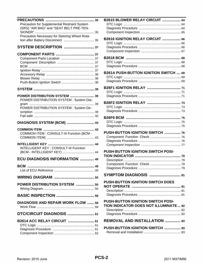
PRECAUTIONS ................................................. 35Precaution for Supplemental Restraint System (SRS) "AIR BAG" and "SEAT BELT PRE-TEN-SIONER" ................................................................. 35Precaution Necessary for Steering Wheel Rota-tion after Battery Disconnect .................................. 35
SYSTEM DESCRIPTION ............................ 37
COMPONENT PARTS ....................................... 37Component Parts Location ..................................... 37Component Description ......................................... 37BCM ........................................................................ 37Ignition Relay .......................................................... 37Accessory Relay ..................................................... 38Blower Relay .......................................................... 38Push-Button Ignition Switch .................................... 38
SYSTEM ............................................................. 39
POWER DISTRIBUTION SYSTEM ........................... 39POWER DISTRIBUTION SYSTEM : System Dia-gram ....................................................................... 39POWER DISTRIBUTION SYSTEM : System De-scription .................................................................. 39Fail-safe .................................................................. 40
DIAGNOSIS SYSTEM (BCM) ............................ 43
COMMON ITEM ........................................................ 43COMMON ITEM : CONSULT-III Function (BCM - COMMON ITEM) .................................................... 43
INTELLIGENT KEY ................................................... 44INTELLIGENT KEY : CONSULT-III Function (BCM - INTELLIGENT KEY) ................................... 44
ECU DIAGNOSIS INFORMATION .............. 49
BCM ................................................................... 49List of ECU Reference ............................................ 49
WIRING DIAGRAM ..................................... 50
POWER DISTRIBUTION SYSTEM ................... 50Wiring Diagram ....................................................... 50
BASIC INSPECTION ................................... 58
DIAGNOSIS AND REPAIR WORK FLOW ........ 58Work Flow ............................................................... 58
DTC/CIRCUIT DIAGNOSIS ......................... 61
B2614 ACC RELAY CIRCUIT ........................... 61DTC Logic ............................................................... 61Diagnosis Procedure .............................................. 61Component Inspection ............................................ 62
B2615 BLOWER RELAY CIRCUIT ................... 64DTC Logic ............................................................... 64Diagnosis Procedure ............................................... 64Component Inspection ............................................ 65
B2616 IGNITION RELAY CIRCUIT ................... 66DTC Logic ............................................................... 66Diagnosis Procedure ............................................... 66Component Inspection ............................................ 67
B2618 BCM ....................................................... 68DTC Logic ............................................................... 68Diagnosis Procedure ............................................... 68
B261A PUSH-BUTTON IGNITION SWITCH ..... 69DTC Logic ............................................................... 69Diagnosis Procedure ............................................... 69
B26F1 IGNITION RELAY .................................. 71DTC Logic ............................................................... 71Diagnosis Procedure ............................................... 71
B26F2 IGNITION RELAY .................................. 73DTC Logic ............................................................... 73Diagnosis Procedure ............................................... 73
B26F6 BCM ....................................................... 75DTC Logic ............................................................... 75Diagnosis Procedure ............................................... 75
PUSH-BUTTON IGNITION SWITCH ................. 76Component Function Check .................................. 76Diagnosis Procedure ............................................... 76Component Inspection ............................................ 77
PUSH-BUTTON IGNITION SWITCH POSI-TION INDICATOR .............................................. 79
Description .............................................................. 79Component Function Check .................................. 79Diagnosis Procedure ............................................... 79
SYMPTOM DIAGNOSIS ............................ 81
PUSH-BUTTON IGNITION SWITCH DOES NOT OPERATE ................................................. 81
Description .............................................................. 81Diagnosis Procedure ............................................... 81
PUSH-BUTTON IGNITION SWITCH POSI-TION INDICATOR DOES NOT ILLUMINATE ... 82
Description .............................................................. 82Diagnosis Procedure ............................................... 82
REMOVAL AND INSTALLATION .............. 83
PUSH-BUTTON IGNITION SWITCH ................. 83Removal and Installation ......................................... 83
PCS-2Revision: 2010 June 2011 M37/M56

CS
PRECAUTIONS[IPDM E/R]
C
D
E
F
G
H
I
J
K
L
B
A
O
P
N
P
< PRECAUTION >
PRECAUTIONPRECAUTIONS
Precaution for Supplemental Restraint System (SRS) "AIR BAG" and "SEAT BELT PRE-TENSIONER" INFOID:0000000006032235
The Supplemental Restraint System such as “AIR BAG” and “SEAT BELT PRE-TENSIONER”, used alongwith a front seat belt, helps to reduce the risk or severity of injury to the driver and front passenger for certaintypes of collision. This system includes seat belt switch inputs and dual stage front air bag modules. The SRSsystem uses the seat belt switches to determine the front air bag deployment, and may only deploy one frontair bag, depending on the severity of a collision and whether the front occupants are belted or unbelted.Information necessary to service the system safely is included in the “SRS AIR BAG” and “SEAT BELT” of thisService Manual.WARNING:• To avoid rendering the SRS inoperative, which could increase the risk of personal injury or death in
the event of a collision that would result in air bag inflation, all maintenance must be performed byan authorized NISSAN/INFINITI dealer.
• Improper maintenance, including incorrect removal and installation of the SRS, can lead to personalinjury caused by unintentional activation of the system. For removal of Spiral Cable and Air BagModule, see the “SRS AIR BAG”.
• Do not use electrical test equipment on any circuit related to the SRS unless instructed to in thisService Manual. SRS wiring harnesses can be identified by yellow and/or orange harnesses or har-ness connectors.
PRECAUTIONS WHEN USING POWER TOOLS (AIR OR ELECTRIC) AND HAMMERSWARNING:• When working near the Air Bag Diagnosis Sensor Unit or other Air Bag System sensors with the
ignition ON or engine running, DO NOT use air or electric power tools or strike near the sensor(s)with a hammer. Heavy vibration could activate the sensor(s) and deploy the air bag(s), possiblycausing serious injury.
• When using air or electric power tools or hammers, always switch the ignition OFF, disconnect thebattery, and wait at least 3 minutes before performing any service.
Precaution Necessary for Steering Wheel Rotation after Battery DisconnectINFOID:0000000006032236
NOTE:• Before removing and installing any control units, first turn the push-button ignition switch to the LOCK posi-
tion, then disconnect both battery cables.• After finishing work, confirm that all control unit connectors are connected properly, then re-connect both
battery cables.• Always use CONSULT-III to perform self-diagnosis as a part of each function inspection after finishing work.
If a DTC is detected, perform trouble diagnosis according to self-diagnosis results.For vehicle with steering lock unit, if the battery is disconnected or discharged, the steering wheel will lock andcannot be turned.If turning the steering wheel is required with the battery disconnected or discharged, follow the operation pro-cedure below before starting the repair operation.
OPERATION PROCEDURE1. Connect both battery cables.
NOTE:Supply power using jumper cables if battery is discharged.
2. Turn the push-button ignition switch to ACC position.(At this time, the steering lock will be released.)
3. Disconnect both battery cables. The steering lock will remain released with both battery cables discon-nected and the steering wheel can be turned.
4. Perform the necessary repair operation.
PCS-3Revision: 2010 June 2011 M37/M56

[IPDM E/R]PRECAUTIONS
< PRECAUTION >5. When the repair work is completed, re-connect both battery cables. With the brake pedal released, turn
the push-button ignition switch from ACC position to ON position, then to LOCK position. (The steeringwheel will lock when the push-button ignition switch is turned to LOCK position.)
6. Perform self-diagnosis check of all control units using CONSULT-III.
Precaution for Procedure without Cowl Top Cover INFOID:0000000006032237
When performing the procedure after removing cowl top cover, coverthe lower end of windshield with urethane, etc.
PIIB3706J
PCS-4Revision: 2010 June 2011 M37/M56

CS
COMPONENT PARTS[IPDM E/R]
C
D
E
F
G
H
I
J
K
L
B
A
O
P
N
P
< SYSTEM DESCRIPTION >
SYSTEM DESCRIPTIONCOMPONENT PARTSIPDM E/R
IPDM E/R : Component Parts Location INFOID:0000000006032092
1. IPDM E/R
A. Engine room dash panel (RH)
JMMIA0369ZZ
PCS-5Revision: 2010 June 2011 M37/M56

[IPDM E/R]SYSTEM
< SYSTEM DESCRIPTION >
SYSTEMRELAY CONTROL SYSTEM
RELAY CONTROL SYSTEM : System Diagram INFOID:0000000006032094
RELAY CONTROL SYSTEM : System Description INFOID:0000000006032095
IPDM E/R activates the internal control circuit to perform the relay ON-OFF control according to the input sig-nals from various sensors and the request signals received from control units via CAN communication.CAUTION:IPDM E/R integrated relays cannot be removed.
JMMIA0373GB
PCS-6Revision: 2010 June 2011 M37/M56

CS
SYSTEM[IPDM E/R]
C
D
E
F
G
H
I
J
K
L
B
A
O
P
N
P
< SYSTEM DESCRIPTION >
NOTE:
BCM controls the starter relay.
RELAY CONTROL SYSTEM : Fail-safe INFOID:0000000006053864
CAN COMMUNICATION CONTROLWhen CAN communication with ECM and BCM is impossible, IPDM E/R performs fail-safe control. After CANcommunication recovers normally, it also returns to normal control.
If No CAN Communication Is Available With ECM
If No CAN Communication Is Available With BCM
Control relay Input/output Transmit unit Control part Reference page
Headlamp low relay• Low beam request signal• Daytime running light re-
quest signalBCM (CAN) Headlamp (LO)
EXL-11
Headlamp high relay High beam request signal BCM (CAN) Headlamp (HI)
Front fog lamp relay Front fog light request signal BCM (CAN) Front fog lamp EXL-19
Tail lamp relay Position light request signal BCM (CAN) Illumination EXL-20
• Front wiper main relay• Front wiper HI/LO relay
Front wiper request signal BCM (CAN)Front wiper motor WW-7
Front wiper position signal Front wiper motor
• Horn relay• Vehicle security horn re-
lay
• Theft warning horn request signal
• Horn reminder signalBCM (CAN)
• Horn (high)• Vehicle security
hornSEC-18
• Starter relayNOTE
• Starter control relay
Starter control relay signal BCM (CAN)
Starter motor• SEC-10• SEC-10
Steering lock unit condition signal
Steering lock unit
Starter relay control signal TCM
Steering lock relay
Steering lock relay signal BCM (CAN)
Steering lock unit SEC-10Steering lock unit condition signal
Steering lock unit
A/T shift selector (Detention switch) signal
A/T shift selector(Detention switch)
A/C relayA/C compressor request sig-nal
ECM (CAN)A/C compressor(magnet clutch)
• HAC-22 (with Forest Air)
• HAC-30 (without Forest Air)
Ignition relay
Ignition switch ON signal BCM (CAN)Each control unit, sensor, actuator and relay (ignition power supply)
PCS-37Vehicle speed signal
Combination meter (CAN)
Push-button ignition switch signal
Push-button ignition switch
Daytime running light relay• Daytime running light re-
quest signal• Position light request signal
BCM (CAN)
• Parking lamp• License plate lamp• Tail lamp• Side marker lamp
EXL-16
Control part Fail-safe operation
Cooling fan• Outputs the pulse duty signal (PWM signal) 100% when the ignition switch is turned ON• Outputs the pulse duty signal (PWM signal) 0% when the ignition switch is turned OFF
A/C compressor A/C relay OFF
Alternator Outputs the power generation command signal (PWM signal) 0%
PCS-7Revision: 2010 June 2011 M37/M56

[IPDM E/R]SYSTEM
< SYSTEM DESCRIPTION >
IGNITION RELAY MALFUNCTION DETECTION FUNCTION• IPDM E/R monitors the voltage at the contact circuit and excitation coil circuit of the ignition relay inside it. • IPDM E/R judges the ignition relay error if the voltage differs between the contact circuit and the excitation
coil circuit.• If the ignition relay cannot turn OFF due to contact seizure, it activates the tail lamp relay and daytime run-
ning light relay for 10 minutes to alert the user to the ignition relay malfunction when the ignition switch isturned OFF.
FRONT WIPER PROTECTION FUNCTIONIPDM E/R detects front wiper stop position by a front wiper stop position signal.When a front wiper stop position signal is in the conditions listed below, IPDM E/R stops power supply to wiperafter repeating a front wiper 10 seconds activation and 20 seconds stop five times.
NOTE:This operation status can be confirmed on the IPDM E/R “Data Monitor” that displays “BLOCK” for the item“WIP PROT” while the wiper is stopped.
STARTER MOTOR PROTECTION FUNCTION
Control part Fail-safe operation
Headlamp• Turns ON the headlamp low relay when the ignition switch is turned ON• Turns OFF the headlamp low relay when the ignition switch is turned OFF• Headlamp high relay OFF
• Parking lamp• License plate lamp• Illumination• Tail lamp• Side marker lamp
• Turns ON the tail lamp relay and daytime running light relay when the ignition switch is turned ON
• Turns OFF the tail lamp relay and daytime running light relay when the ignition switch is turned OFF
Front wiper motor
• The status just before activation of fail-safe control is maintained until the ignition switch is turned OFF while the front wiper is operating at LO or HI speed.
• The wiper is operated at LO speed until the ignition switch is turned OFF if the fail-safe control is activated while the front wiper is set in the AUTO mode and the front wiper motor is operating.
• Returns automatically wiper to stop position when ignition switch is turned ON if fail-safe control is activated while front wiper motor is operated and wiper stop in the other than stop position.
Front fog lamp Front fog lamp relay OFF
Horn Horn OFF
Ignition relay The status just before activation of fail-safe is maintained.
Starter motor Starter control relay OFF
Steering lock unit Steering lock relay OFF
Voltage judgment
IPDM E/R judgment OperationIgnition relay contact side
Ignition relay excitation coil side
ON ON Ignition relay ON normal —
OFF OFF Ignition relay OFF normal —
ON OFF Ignition relay ON stuck
• Detects DTC “B2098: IGN RELAY ON”
• Turns ON the tail lamp relay and daytime running light relay for 10 minutes
OFF ON Ignition relay OFF stuckDetects DTC “B2099: IGN RELAY OFF”
Ignition switch Front wiper switch Front wiper stop position signal
ONOFF The front wiper stop position signal (stop position) cannot be input for 10 seconds.
ON The front wiper stop position signal does not change for 10 seconds.
PCS-8Revision: 2010 June 2011 M37/M56

CS
SYSTEM[IPDM E/R]
C
D
E
F
G
H
I
J
K
L
B
A
O
P
N
P
< SYSTEM DESCRIPTION >IPDM E/R turns OFF the starter control relay to protect the starter motor when the starter control relay remainsactive for 90 seconds.POWER CONTROL SYSTEM
POWER CONTROL SYSTEM : System Diagram INFOID:0000000006032097
POWER CONTROL SYSTEM : System Description INFOID:0000000006032098
COOLING FAN CONTROLIPDM E/R outputs pulse duty signal (PWM signal) to the cooling fan control module according to the status ofthe cooling fan speed request signal received from ECM via CAN communication. Refer to EC-50, "COOLINGFAN CONTROL : System Diagram" (VQ37VHR) or EC-575, "COOLING FAN CONTROL : System Diagram"(VK56VD).
ALTERNATOR CONTROLIPDM E/R outputs power generation command signal (PWM signal) to the alternator according to the status ofthe power generation command value signal received from ECM via CAN communication. Refer to CHG-8,"POWER GENERATION VOLTAGE VARIABLE CONTROL SYSTEM : System Diagram".SIGNAL BUFFER SYSTEM
SIGNAL BUFFER SYSTEM : System Diagram INFOID:0000000006032099
SIGNAL BUFFER SYSTEM : System Description INFOID:0000000006032100
• IPDM E/R reads the status of the oil pressure switch and transmits the oil pressure switch signal to BCM viaCAN communication (only for models with VQ37VHR engine). Refer to MWI-15, "OIL PRESSURE WARN-ING LAMP : System Diagram".
• IPDM E/R reads the status of the hood switch and transmits the hood switch signal to BCM via CAN commu-nication. Refer to SEC-10, "Hood Switch".
• IPDM E/R receives the rear window defogger control signal from BCM via CAN communication and trans-mits it to ECM and AV control unit via CAN communication. Refer to DEF-6, "System Diagram".
POWER CONSUMPTION CONTROL SYSTEM
JSMIA0004GB
JPMIA0952GB
PCS-9Revision: 2010 June 2011 M37/M56

[IPDM E/R]SYSTEM
< SYSTEM DESCRIPTION >
POWER CONSUMPTION CONTROL SYSTEM : System Diagram INFOID:0000000006069107
POWER CONSUMPTION CONTROL SYSTEM : System Description INFOID:0000000006032102
OUTLINE• IPDM E/R incorporates a power consumption control function that reduces the power consumption accord-
ing to the vehicle status. • IPDM E/R changes its status (control mode) with the sleep wake up signal received from BCM via CAN com-
munication.
Normal mode (wake-up)- CAN communication is normally performed with other control units.- Individual unit control by IPDM E/R is normally performed.
Low power consumption mode (sleep)- Low power consumption control is active.- CAN transmission is stopped.
SLEEP MODE ACTIVATION• IPDM E/R judges that the sleep-ready conditions are fulfilled when the ignition switch is OFF and none of the
conditions below are present. Then it transmits a sleep-ready signal (ready) to BCM via CAN communica-tion.
- Outputting signals to actuators- Switches or relays operating- Hood switch status is kept 50 ms or less.- Output requests are being received from control units via CAN communication.• IPDM E/R stops CAN communication and enters the low power consumption mode when it receives a sleep
wake up signal (sleep) from BCM and the sleep-ready conditions are fulfilled.
WAKE-UP OPERATION• IPDM E/R changes from the low power consumption mode to the normal mode when it receives a sleep
wake-up signal (wake up) from BCM or any of the following conditions is fulfilled. In addition, it transmits asleep-ready signal (not-ready) to BCM via CAN communication to report the CAN communication start.
- Ignition switch ON- The hood switch status changes.- An output request is received from a control unit via CAN communication.
JMMIA0427GB
PCS-10Revision: 2010 June 2011 M37/M56

CS
DIAGNOSIS SYSTEM (IPDM E/R)[IPDM E/R]
C
D
E
F
G
H
I
J
K
L
B
A
O
P
N
P
< SYSTEM DESCRIPTION >
DIAGNOSIS SYSTEM (IPDM E/R)
Diagnosis Description INFOID:0000000006032103
AUTO ACTIVE TEST
DescriptionIn auto active test, the IPDM E/R sends a drive signal to the following systems to check their operation.• Oil pressure warning lamp (only for models with VQ37VHR engine)• Front wiper (LO, HI)• Parking lamp• License plate lamp• Tail lamp• Side marker lamp• Front fog lamp• Headlamp (LO, HI)• A/C compressor (magnet clutch)• Cooling fan (cooling fan control module)
Operation ProcedureCAUTION:Never perform auto active test in the following condition.• Engine is running• CONSULT-III is connected 1. Close the hood and lift the wiper arms from the windshield. (Prevent windshield damage due to wiper
operation)NOTE:When auto active test is performed with hood opened, sprinkle water on windshield beforehand.
2. Turn the ignition switch OFF.3. Turn the ignition switch ON, and within 20 seconds, press the front door switch (driver side) 10 times.
Then turn the ignition switch OFF.CAUTION:Close passenger door.
4. Turn the ignition switch ON within 10 seconds. After that the horn sounds once and the auto active teststarts.CAUTION:Engine starts when ignition switch is turned ON while brake pedal is depressed.
5. The oil pressure warning lamp starts blinking when the auto active test starts.6. After a series of the following operations is repeated 3 times, auto active test is completed.NOTE:• When auto active test has to be cancelled halfway through test, turn the ignition switch OFF.• When auto active test is not activated, door switch may be the cause. Check door switch. Refer to DLK-72,
"Component Function Check".
Inspection in Auto Active TestWhen auto active test is actuated, the following 6 steps are repeated 3 times.
Operation sequence
Inspection location Operation
1Oil pressure warning lamp(only for models with VQ37VHR engine)
Blinks continuously during operation of auto active test
2 Front wiper motor LO for 5 seconds → HI for 5 seconds
3
• Parking lamp• License plate lamp• Tail lamp• Side marker lamp• Front fog lamp
10 seconds
4 Headlamp• LO 10 seconds• HI ON ⇔ OFF 5 times
PCS-11Revision: 2010 June 2011 M37/M56

[IPDM E/R]DIAGNOSIS SYSTEM (IPDM E/R)
< SYSTEM DESCRIPTION >
*: Outputs duty ratio of 50% for 5 seconds → duty ratio of 100% for 5 seconds on the cooling fan control module.
Concept of auto active test
• IPDM E/R starts the auto active test with the door switch signals transmitted by BCM via CAN communica-tion. Therefore, the CAN communication line between IPDM E/R and BCM is considered normal if the autoactive test starts successfully.
• The auto active test facilitates troubleshooting if any systems controlled by IPDM E/R cannot be operated.
Diagnosis chart in auto active test
5 A/C compressor (magnet clutch) ON ⇔ OFF 5 times
6 Cooling fan MID for 5 seconds → HI for 5 seconds
Operation sequence
Inspection location Operation
JMMIA0374GB
Symptom Inspection contents Possible cause
Any of the following components do not operate• Parking lamp• License plate lamp• Tail lamp• Side marker lamp• Front fog lamp• Headlamp (HI, LO)• Front wiper motor
Perform auto active test.Does the applicable system op-erate?
YES BCM signal input circuit
NO
• Lamp or motor• Lamp or motor ground circuit• Harness or connector between
IPDM E/R and applicable system• IPDM E/R
A/C compressor does not operatePerform auto active test.Does the magnet clutch oper-ate?
YES
• Combination meter signal input cir-cuit
• CAN communication signal be-tween Combination meter and ECM
• CAN communication signal be-tween ECM and IPDM E/R
NO
• Magnet clutch• Harness or connector between
IPDM E/R and magnet clutch• IPDM E/R
Oil pressure warning lamp does not operate(only for models with VQ37VHR engine)
Perform auto active test.Does the oil pressure warning lamp blink?
YES
• Harness or connector between IPDM E/R and oil pressure switch
• Oil pressure switch• IPDM E/R
NO
• CAN communication signal be-tween IPDM E/R and BCM
• CAN communication signal be-tween BCM and Combination meter
• Combination meter
PCS-12Revision: 2010 June 2011 M37/M56

CS
DIAGNOSIS SYSTEM (IPDM E/R)[IPDM E/R]
C
D
E
F
G
H
I
J
K
L
B
A
O
P
N
P
< SYSTEM DESCRIPTION >
CONSULT-III Function (IPDM E/R) INFOID:0000000006032104
APPLICATION ITEMCONSULT-III performs the following functions via CAN communication with IPDM E/R.
SELF DIAGNOSTIC RESULTRefer to PCS-24, "DTC Index".
DATA MONITORMonitor item
Cooling fan does not operatePerform auto active test.Does the cooling fan operate?
YES• ECM signal input circuit• CAN communication signal be-
tween ECM and IPDM E/R
NO
• Cooling fan• Harness or connector between
cooling fan and cooling fan control module
• Cooling fan control module• Harness or connector between
IPDM E/R and cooling fan control module
• Cooling fan relay• Harness or connector between
IPDM E/R and cooling fan relay• IPDM E/R
Symptom Inspection contents Possible cause
Diagnosis mode Description
Ecu Identification Allows confirmation of IPDM E/R part number.
Self Diagnostic Result Displays the diagnosis results judged by IPDM E/R.
Data Monitor Displays the real-time input/output data from IPDM E/R input/output data.
Active Test IPDM E/R can provide a drive signal to electronic components to check their operations.
CAN Diag Support Monitor The results of transmit/receive diagnosis of CAN communication can be read.
Monitor Item[Unit]
MAIN SIG-NALS
Description
RAD FAN REQ[%]
× Displays the value of the cooling fan speed signal received from ECM via CAN com-munication.
AC COMP REQ[Off/On]
× Displays the status of the A/C compressor request signal received from ECM via CAN communication.
TAIL&CLR REQ[Off/On]
× Displays the status of the position light request signal received from BCM via CAN communication.
HL LO REQ[Off/On]
× Displays the status of the low beam request signal received from BCM via CAN com-munication.
HL HI REQ[Off/On]
× Displays the status of the high beam request signal received from BCM via CAN communication.
FR FOG REQ[Off/On]
× Displays the status of the front fog light request signal received from BCM via CAN communication.
FR WIP REQ[Stop/1LOW/Low/Hi]
× Displays the status of the front wiper request signal received from BCM via CAN communication.
WIP AUTO STOP[STOP P/ACT P]
× Displays the status of the front wiper stop position signal judged by IPDM E/R.
WIP PROT[Off/BLOCK]
× Displays the status of the front wiper fail-safe operation judged by IPDM E/R.
IGN RLY1 -REQ[Off/On]
Displays the status of the ignition switch ON signal received from BCM via CAN com-munication.
PCS-13Revision: 2010 June 2011 M37/M56

[IPDM E/R]DIAGNOSIS SYSTEM (IPDM E/R)
< SYSTEM DESCRIPTION >
ACTIVE TESTTest item
IGN RLY[Off/On]
× Displays the status of the ignition relay judged by IPDM E/R.
PUSH SW[Off/On]
Displays the status of the push-button ignition switch judged by IPDM E/R.
INTER/NP SW[Off/On]
Displays the status of the shift position judged by IPDM E/R.
ST RLY CONT[Off/On]
Displays the status of the starter relay status signal received from BCM via CAN communication.
IHBT RLY -REQ[Off/On]
Displays the status of the starter control relay signal received from BCM via CAN communication.
ST/INHI RLY[Off/ ST /INHI/UNKWN]
Displays the status of the starter relay and starter control relay judged by IPDM E/R.
DETENT SW[Off/On]
Displays the status of the A/T shift selector (detention switch) judged by IPDM E/R.
S/L RLY -REQ[Off/On]
Displays the status of the steering lock relay request received from BCM via CAN communication.
S/L STATE[LOCK/UNLOCK/UNKWN]
Displays the status of the steering lock judged by IPDM E/R.
DTRL REQ[Off/On]
Displays the status of the daytime running light request signal received from BCM via CAN communication.NOTE:This item is monitored only on the vehicle with daytime running light system.
OIL P SW[Open/Close]
Displays the status of the oil pressure switch judged by IPDM E/R.NOTE:This item is monitored only on the vehicle with VQ37VHR engine models.
HOOD SW[Off/On]
Displays the status of the hood switch judged by IPDM E/R.
HL WASHER REQ[Off/On]
NOTE:The item is indicated, but not monitored.
THFT HRN REQ[Off/On]
Displays the status of the theft warning horn request signal received from BCM via CAN communication.
HORN CHIRP[Off/On]
Displays the status of the horn reminder signal received from BCM via CAN commu-nication.
CRNRNG LMP REQ[Off/On]
NOTE:The item is indicated, but not monitored.
Monitor Item[Unit]
MAIN SIG-NALS
Description
Test item Operation Description
CORNERING LAMP
OffNOTE:The item is indicated, but cannot be tested.
LH
RH
HORN On Operates horn relay for 20 ms.
FRONT WIPER
Off OFF
Lo Operates the front wiper relay.
Hi Operates the front wiper relay and front wiper high relay.
PCS-14Revision: 2010 June 2011 M37/M56

CS
DIAGNOSIS SYSTEM (IPDM E/R)[IPDM E/R]
C
D
E
F
G
H
I
J
K
L
B
A
O
P
N
P
< SYSTEM DESCRIPTION >
MOTOR FAN
1 OFF
2 Transmits 50% pulse duty signal (PWM signal) to the cooling fan control module.
3 Transmits 75% pulse duty signal (PWM signal) to the cooling fan control module.
4Transmits 100% pulse duty signal (PWM signal) to the cooling fan control mod-ule.
HEAD LAMP WASHER OnNOTE:The item is indicated, but cannot be tested.
EXTERNAL LAMPS
Off OFF
TAIL Operates the tail lamp relay and the daytime running light relay.
Lo Operates the headlamp low relay.
HiOperates the headlamp low relay and ON/OFF the headlamp high relay at 1 sec-ond intervals.
Fog Operates the front fog lamp relay.
Test item Operation Description
PCS-15Revision: 2010 June 2011 M37/M56

[IPDM E/R]IPDM E/R
< ECU DIAGNOSIS INFORMATION >
ECU DIAGNOSIS INFORMATIONIPDM E/R
Reference Value INFOID:0000000006032105
VALUES ON THE DIAGNOSIS TOOL
Monitor Item Condition Value/Status
RAD FAN REQ Engine idle speedChanges depending on engine coolant temperature, air conditioner operation status, vehicle speed, etc.
0 – 100 %
AC COMP REQ Engine running
A/C switch OFF Off
A/C switch ON(compressor is operating)
On
TAIL&CLR REQ
Lighting switch OFF Off
• Lighting switch 1ST, 2ND or AUTO (light is illuminated)• Daytime running light system is operated
On
HL LO REQ
Lighting switch OFF Off
Lighting switch 2ND or AUTO (light is illuminated)On
Daytime running light system is operated
HL HI REQLighting switch 2ND orAUTO (light is illuminated)
Lighting switch other than HI and PASS Off
Lighting switch HI or PASS On
FR FOG REQLighting switch 2ND orAUTO (light is illuminated)
Front fog lamp switch OFFOff
Lighting switch HI or PASS
Front fog lamp switch ON On
FR WIP REQ Ignition switch ON
Front wiper switch OFF Stop
Front wiper switch AUTO 1LOW
Front wiper switch LO Low
Front wiper switch HI Hi
WIP AUTO STOP Ignition switch ON
Front wiper stop position STOP P
Any position other than front wiper stop position
ACT P
WIP PROT Ignition switch ONFront wiper operates normally Off
Front wiper stops at fail-safe operation BLOCK
IGN RLY1 -REQIgnition switch OFF or ACC Off
Ignition switch ON On
IGN RLYIgnition switch OFF or ACC Off
Ignition switch ON On
PUSH SWRelease the push-button ignition switch Off
Press the push-button ignition switch On
INTER/NP SW Ignition switch ON
Selector lever in any position other than P or N
Off
Selector lever in P or N position On
ST RLY CONTIgnition switch ON Off
At engine cranking On
IHBT RLY -REQIgnition switch ON Off
At engine cranking On
PCS-16Revision: 2010 June 2011 M37/M56

CS
IPDM E/R[IPDM E/R]
C
D
E
F
G
H
I
J
K
L
B
A
O
P
N
P
< ECU DIAGNOSIS INFORMATION >
ST/INHI RLY
Ignition switch ON Off
At engine cranking INHI → ST
The status of starter relay or starter control relay cannot be recognized by the battery voltage malfunction, etc. when the starter relay is ON and the starter control relay is OFF
UNKWN
DETENT SWIgnition switch ON
• Press the selector button with selec-tor lever in P position
• Selector lever in any position other than P
Off
Release the selector button with selector lever in P position On
S/L RLY -REQ
None of the conditions below are present Off
• Open the driver door after the ignition switch is turned OFF (for a few sec-onds)
• Press the push-button ignition switch when the steering lock is activatedOn
S/L STATE
Steering lock is activated LOCK
Steering lock is deactivated UNLOCK
[DTC: B210A] is detected UNKWN
DTRL REQ
Daytime running light system is not operated Off
Any of the condition below• Daytime running light system is operated• Light switch 1ST, 2ND or AUTO (light is illuminated)
On
OIL P SW
Ignition switch OFF or ACCOpen
Ignition switch ON (engine running)
Ignition switch ON (engine stopped) Close
HOOD SWClose the hood Off
Open the hood On
HL WASHER REQNOTE:The item is indicated, but not monitored.
Off
THFT HRN REQ
Not operation Off
• Panic alarm is activated• Theft warning alarm is activated
On
HORN CHIRPNot operation Off
Door locking with Intelligent Key (horn chirp mode) On
CRNRNG LMP REQNOTE:The item is indicated, but not monitored.
Off
Monitor Item Condition Value/Status
PCS-17Revision: 2010 June 2011 M37/M56

[IPDM E/R]IPDM E/R
< ECU DIAGNOSIS INFORMATION >
TERMINAL LAYOUT
PHYSICAL VALUES
JSMIA0001ZZ
Terminal No.(Wire color)
Description
ConditionValue
(Approx.)Signal nameInput/ Output+ −
1(W)
Ground Battery power supply Input Ignition switch OFF Battery voltage
2(L)
Ground Battery power supply Input Ignition switch OFF Battery voltage
4(W)
GroundECM relay powersupply
Output
Ignition switch OFF(More than a few seconds after turning igni-tion switch OFF)
0 V
• Ignition switch ON• Ignition switch OFF
(For a few seconds after turning ignition switch OFF)
Battery voltage
5(P)
GroundECM relay powersupply
Output
Ignition switch OFF(More than a few seconds after turning igni-tion switch OFF)
0 V
• Ignition switch ON• Ignition switch OFF
(For a few seconds after turning ignition switch OFF)
Battery voltage
PCS-18Revision: 2010 June 2011 M37/M56

CS
IPDM E/R[IPDM E/R]
C
D
E
F
G
H
I
J
K
L
B
A
O
P
N
P
< ECU DIAGNOSIS INFORMATION >
6(R)
GroundECM relay powersupply
Output
Ignition switch OFF(More than a few seconds after turning igni-tion switch OFF)
0 V
• Ignition switch ON• Ignition switch OFF
(For a few seconds after turning ignition switch OFF)
Battery voltage
7(Y)
GroundThrottle control motor relay power supply
Output
Ignition switch OFF(More than a few seconds after turning igni-tion switch OFF)
0 V
• Ignition switch ON• Ignition switch OFF
(For a few seconds after turning ignition switch OFF)
Battery voltage
8(L)
GroundA/C relay powersupply
Output Engine running
A/C switch OFF 0 V
A/C switch ON(A/C compressor is oper-ating)
Battery voltage
10(V)
Ground ECM power supply Output Ignition switch OFF Battery voltage
11(B)
Ground Ground — Ignition switch ON 0 V
12(G)
GroundIgnition relay power supply
OutputIgnition switch OFF or ACC 0 V
Ignition switch ON Battery voltage
13(GR)
GroundFuel pump powersupply
Output
Approximately 1 second or more after turning the ignition switch ON
0 V
• Approximately 1 second after turning the ignition switch ON
• Engine runningBattery voltage
16(V)
GroundFront wiper stop posi-tion
InputIgnition switch ON
Front wiper stop position 0 V
Any position other than front wiper stop position
12 V
18(Y)
Ground Ignition relay monitor InputIgnition switch OFF or ACC Battery voltage
Ignition switch ON 0 V
Terminal No.(Wire color)
Description
ConditionValue
(Approx.)Signal nameInput/ Output+ −
PCS-19Revision: 2010 June 2011 M37/M56

[IPDM E/R]IPDM E/R
< ECU DIAGNOSIS INFORMATION >
22(BR)
GroundPower generation command signal
Output
Ignition switch ON
6.3 V
40% is set on “ACTIVE TEST”, “ALTERNA-TOR DUTY” of “ENGINE”
3.8 V
80% is set on “ACTIVE TEST”, “ALTERNA-TOR DUTY” of “ENGINE”
1.4 V
23(SB)
GroundDaytime running light relay control
Output
• Parking lamp• License plate
lamp• Tail lamp
Turned OFF Battery voltage
Turned ON 0 V
24(O)
Ground Hood switch InputClose the hood 12 V
Open the hood 0 V
25(LG)
GroundIgnition relay power supply
OutputIgnition switch OFF or ACC 0 V
Ignition switch ON Battery voltage
30(BR)
GroundPush-button ignition switch
InputPress the push-button ignition switch 0 V
Release the push-button ignition switch 12 V
31(W)
Ground Starter relay control InputIgnition switch ON
Selector lever in any posi-tion other than P or N
0 V
Selector lever P or N 12 V
32(L)
GroundSteering lock unitcondition-1
InputSteering lock is activated 0 V
Steering lock is deactivated 12 V
34(P)
GroundSteering lock unitcondition-2
InputSteering lock is activated 12 V
Steering lock is deactivated 0 V
36(GR)
Ground Battery power supply Input Ignition switch OFF Battery voltage
39(P)
— CAN-LInput/ Output
— —
40(L)
— CAN-HInput/ Output
— —
41(B)
Ground Ground — Ignition switch ON 0 V
Terminal No.(Wire color)
Description
ConditionValue
(Approx.)Signal nameInput/ Output+ −
JPMIA0001GB
JPMIA0002GB
JPMIA0003GB
PCS-20Revision: 2010 June 2011 M37/M56
CS
IPDM E/R[IPDM E/R]
C
D
E
F
G
H
I
J
K
L
B
A
O
P
N
P
< ECU DIAGNOSIS INFORMATION >
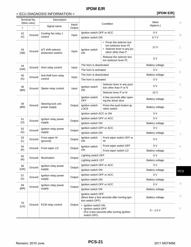
42(V)
GroundCooling fan relay 1control
InputIgnition switch OFF or ACC 0 V
Ignition switch ON 0.7 V
43(SB)
GroundA/T shift selector(Detention switch)
InputIgnition switch ON
• Press the selector but-ton (selector lever P)
• Selector lever in any po-sition other than P
12 V
Release the selector but-ton (selector lever P)
0 V
44(GR)
Ground Horn relay control InputThe horn is deactivated Battery voltage
The horn is activated 0 V
45(G)
GroundAnti theft horn relay control
InputThe horn is deactivated Battery voltage
The horn is activated 0 V
46(BR)
Ground Starter relay control InputIgnition switch ON
Selector lever in any posi-tion other than P or N
0 V
Selector lever P or N 12 V
49(BR)
GroundSteering lock unitpower supply
Output
Ignition switch OFF
A few seconds after open-ing the driver door
Battery voltage
Ignition switch LOCK
Press the push-button ig-nition switch
Battery voltage
Ignition switch ACC or ON 0 V
51(O)
GroundIgnition relay power supply
OutputIgnition switch OFF or ACC 0 V
Ignition switch ON Battery voltage
52(G)
GroundIgnition relay power supply
OutputIgnition switch OFF or ACC 0 V
Ignition switch ON Battery voltage
53(L)
GroundFront wiper HI (ground)
OutputIgnition switch ON
Front wiper switch OFF or HI
0 V
54(P)
Ground Front wiper LO OutputIgnition switch ON
Front wiper switch OFF 0 V
Front wiper switch LO Battery voltage
55(R)
Ground Illumination OutputLighting switch OFF 0 V
Lighting switch 1ST Battery voltage
56(GR)
GroundIgnition relay power supply
OutputIgnition switch OFF or ACC 0 V
Ignition switch ON Battery voltage
57(V)
GroundIgnition relay power supply
OutputIgnition switch OFF or ACC 0 V
Ignition switch ON Battery voltage
58(BR)
GroundIgnition relay power supply
OutputIgnition switch OFF or ACC 0 V
Ignition switch ON Battery voltage
70(LG)
Ground ECM relay control Output
Ignition switch OFF(More than a few seconds after turning igni-tion switch OFF)
Battery voltage
• Ignition switch ON• Ignition switch OFF
(For a few seconds after turning ignition switch OFF)
0 – 1.5 V
Terminal No.(Wire color)
Description
ConditionValue
(Approx.)Signal nameInput/ Output+ −
PCS-21Revision: 2010 June 2011 M37/M56

[IPDM E/R]IPDM E/R
< ECU DIAGNOSIS INFORMATION >
71(O)
GroundThrottle control motor relay control
OutputIgnition switch ON → OFF
0 – 1.0 V ↓
Battery voltage↓
0 V
Ignition switch ON 0 – 1.0 V
73(G)
GroundIgnition relay power supply
OutputIgnition switch OFF or ACC 0 V
Ignition switch ON Battery voltage
74(R)
GroundIgnition relay power supply
OutputIgnition switch OFF or ACC 0 V
Ignition switch ON Battery voltage
75*(Y)
Ground Oil pressure switch InputIgnition switch ON
Engine stopped 0 V
Engine running 12 V
77(B)
GroundFuel pump relaycontrol
Output
• Approximately 1 second after turning the ignition switch ON
• Engine running0 – 1.0 V
Approximately 1 second or more after turning the ignition switch ON
Battery voltage
80(W)
Ground Starter motor Output At engine cranking Battery voltage
83(R)
Ground Headlamp LO (RH) Output
Lighting switch OFF 0 V
Lighting switch 2ND or AUTO (light is illumi-nated) Battery voltage
Daytime running light operated
84(W)
Ground Headlamp LO (LH) Output
Lighting switch OFF 0 V
Lighting switch 2ND or AUTO (light is illumi-nated) Battery voltage
Daytime running light operated
86(G)
Ground Front fog lamp (RH) Output
Lighting switch 2ND or AUTO (light is illumi-nated)
Front fog lamp switch ON Battery voltage
Lighting switch HI or PASS0 V
Front fog lamp switch OFF
87(L)
Ground Front fog lamp (LH) Output
Lighting switch 2ND or AUTO (light is illumi-nated)
Front fog lamp switch ON Battery voltage
Lighting switch HI or PASS0 V
Front fog lamp switch OFF
88(O)
GroundFront wiper motor power supply
Output Ignition switch ON Battery voltage
89(Y)
Ground Headlamp HI (RH) Output
Lighting switch 2ND or AUTO (light is illumi-nated)
Lighting switch HI or PASS Battery voltage
Lighting switch other than HI and PASS
0 V
90(P)
Ground Headlamp HI (LH) Output
Lighting switch 2ND or AUTO (light is illumi-nated)
Lighting switch HI or PASS Battery voltage
Lighting switch other than HI and PASS
0 V
Terminal No.(Wire color)
Description
ConditionValue
(Approx.)Signal nameInput/ Output+ −
PCS-22Revision: 2010 June 2011 M37/M56

CS
IPDM E/R[IPDM E/R]
C
D
E
F
G
H
I
J
K
L
B
A
O
P
N
P
< ECU DIAGNOSIS INFORMATION >
*: For models with VQ37VHR engine
Fail-safe INFOID:0000000006032106
CAN COMMUNICATION CONTROLWhen CAN communication with ECM and BCM is impossible, IPDM E/R performs fail-safe control. After CANcommunication recovers normally, it also returns to normal control.
If No CAN Communication Is Available With ECM
If No CAN Communication Is Available With BCM
IGNITION RELAY MALFUNCTION DETECTION FUNCTION• IPDM E/R monitors the voltage at the contact circuit and excitation coil circuit of the ignition relay inside it. • IPDM E/R judges the ignition relay error if the voltage differs between the contact circuit and the excitation
coil circuit.
96(R)
Ground Wiper reverse relay Input
Ignition switch OFF or ACC 0 V
Ignition switch ON Battery voltage
Front wiper operates at LO Battery voltage
Front wiper operates at HI 0 V
97(V)
Ground Cooling fan control Output Engine idling 0 – 5 V
Terminal No.(Wire color)
Description
ConditionValue
(Approx.)Signal nameInput/ Output+ −
Control part Fail-safe operation
Cooling fan• Outputs the pulse duty signal (PWM signal) 100% when the ignition switch is turned ON• Outputs the pulse duty signal (PWM signal) 0% when the ignition switch is turned OFF
A/C compressor A/C relay OFF
Alternator Outputs the power generation command signal (PWM signal) 0%
Control part Fail-safe operation
Headlamp• Turns ON the headlamp low relay when the ignition switch is turned ON• Turns OFF the headlamp low relay when the ignition switch is turned OFF• Headlamp high relay OFF
• Parking lamp• License plate lamp• Illumination• Tail lamp• Side marker lamp
• Turns ON the tail lamp relay and daytime running light relay when the ignition switch is turned ON
• Turns OFF the tail lamp relay and daytime running light relay when the ignition switch is turned OFF
Front wiper motor
• The status just before activation of fail-safe control is maintained until the ignition switch is turned OFF while the front wiper is operating at LO or HI speed.
• The wiper is operated at LO speed until the ignition switch is turned OFF if the fail-safe control is activated while the front wiper is set in the AUTO mode and the front wiper motor is operating.
• Returns automatically wiper to stop position when ignition switch is turned ON if fail-safe control is activated while front wiper motor is operated and wiper stop in the other than stop position.
Front fog lamp Front fog lamp relay OFF
Horn Horn OFF
Ignition relay The status just before activation of fail-safe is maintained.
Starter motor Starter control relay OFF
Steering lock unit Steering lock relay OFF
PCS-23Revision: 2010 June 2011 M37/M56

[IPDM E/R]IPDM E/R
< ECU DIAGNOSIS INFORMATION >• If the ignition relay cannot turn OFF due to contact seizure, it activates the tail lamp relay and daytime run-
ning light relay for 10 minutes to alert the user to the ignition relay malfunction when the ignition switch isturned OFF.
FRONT WIPER PROTECTION FUNCTIONIPDM E/R detects front wiper stop position by a front wiper stop position signal.When a front wiper stop position signal is in the conditions listed below, IPDM E/R stops power supply to wiperafter repeating a front wiper 10 seconds activation and 20 seconds stop five times.
NOTE:This operation status can be confirmed on the IPDM E/R “Data Monitor” that displays “BLOCK” for the item“WIP PROT” while the wiper is stopped.
STARTER MOTOR PROTECTION FUNCTIONIPDM E/R turns OFF the starter control relay to protect the starter motor when the starter control relay remainsactive for 90 seconds.
DTC Index INFOID:0000000006032107
NOTE:• The details of time display are as follows.- CRNT: A malfunction is detected now.- PAST: A malfunction was detected in the past.• IGN counter is displayed on FFD (Freeze Frame Data).- The number is 0 when is detected now.- The number increases like 1 → 2 ··· 38 → 39 after returning to the normal condition whenever IGN OFF →
ON.- The number is fixed to 39 until the self-diagnosis results are erased if it is over 39.
×: Applicable
Voltage judgment
IPDM E/R judgment OperationIgnition relay contact side
Ignition relay excitation coil side
ON ON Ignition relay ON normal —
OFF OFF Ignition relay OFF normal —
ON OFF Ignition relay ON stuck
• Detects DTC “B2098: IGN RELAY ON”
• Turns ON the tail lamp relay and daytime running light relay for 10 minutes
OFF ON Ignition relay OFF stuckDetects DTC “B2099: IGN RELAY OFF”
Ignition switch Front wiper switch Front wiper stop position signal
ONOFF The front wiper stop position signal (stop position) cannot be input for 10 seconds.
ON The front wiper stop position signal does not change for 10 seconds.
CONSULT display Fail-safe Reference*
No DTC is detected.further testingmay be required.
— —
U1000: CAN COMM CIRCUIT × PCS-29
B2098: IGN RELAY ON × PCS-30
B2099: IGN RELAY OFF — PCS-31
B2108: STRG LCK RELAY ON — SEC-122
B2109: STRG LCK RELAY OFF — SEC-123
B210A: STRG LCK STATE SW — SEC-124
B210B: PNP RELAY ON — SEC-126
PCS-24Revision: 2010 June 2011 M37/M56
CS
IPDM E/R[IPDM E/R]
C
D
E
F
G
H
I
J
K
L
B
A
O
P
N
P
< ECU DIAGNOSIS INFORMATION >
B210C: PNP RELAY OFF — SEC-127
B210D: STARTER RELAY ON — SEC-128
B210E: STARTER RELAY OFF — SEC-129
B210F: INTRLCK/PNP SW ON — SEC-131
B2110: INTRLCK/PNP SW OFF — SEC-133
CONSULT display Fail-safe Reference*
PCS-25Revision: 2010 June 2011 M37/M56

[IPDM E/R]IPDM E/R
< WIRING DIAGRAM >
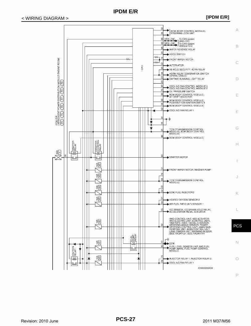
WIRING DIAGRAMIPDM E/R
Wiring Diagram INFOID:0000000006032108
JCMWA5568GB
PCS-26Revision: 2010 June 2011 M37/M56
CS
IPDM E/R[IPDM E/R]
C
D
E
F
G
H
I
J
K
L
B
A
O
P
N
P
< WIRING DIAGRAM >
JCMWA5569GB
PCS-27Revision: 2010 June 2011 M37/M56

[IPDM E/R]IPDM E/R
< WIRING DIAGRAM >
JCMWA5570GB
PCS-28Revision: 2010 June 2011 M37/M56

CS
U1000 CAN COMM CIRCUIT[IPDM E/R]
C
D
E
F
G
H
I
J
K
L
B
A
O
P
N
P
< DTC/CIRCUIT DIAGNOSIS >
DTC/CIRCUIT DIAGNOSISU1000 CAN COMM CIRCUIT
Description INFOID:0000000006032112
CAN (Controller Area Network) is a serial communication line for real time applications. It is an on-vehicle mul-tiplex communication line with high data communication speed and excellent error detection ability. Modernvehicle is equipped with many electronic control unit, and each control unit shares information and links withother control units during operation (not independent). In CAN communication, control units are connectedwith 2 communication lines (CAN-H line, CAN-L line) allowing a high rate of information transmission with lesswiring. Each control unit transmits/receives data but selectively reads required data only.CAN Communication Signal Chart. Refer to LAN-35, "CAN COMMUNICATION SYSTEM : CAN Communica-tion Signal Chart".
DTC Logic INFOID:0000000006032113
DTC DETECTION LOGIC
Diagnosis Procedure INFOID:0000000006032114
1.PERFORM SELF DIAGNOSTIC
1. Turn ignition switch ON and wait 2 seconds or more.2. Check “Self Diagnostic Result” of “IPDM E/R” using CONSULT-III.Is DTC “U1000” displayed?YES >> Refer to LAN-25, "Trouble Diagnosis Flow Chart".NO >> Refer to GI-38, "Intermittent Incident".
DTCCONSULT-III display
descriptionDTC Detection Condition Possible cause
U1000 CAN COMM CIRCUITWhen IPDM E/R cannot communicate CAN communication signal continuously for 2 seconds or more
CAN communication system
PCS-29Revision: 2010 June 2011 M37/M56

[IPDM E/R]B2098 IGNITION RELAY ON STUCK
< DTC/CIRCUIT DIAGNOSIS >
B2098 IGNITION RELAY ON STUCK
Description INFOID:0000000006032115
• IPDM E/R operates the ignition relay when it receives an ignition switch ON signal from BCM via CAN com-munication.
• Turn the ignition relay OFF by pressing the push-button ignition switch once when the vehicle speed is 4 km/h (2.5 MPH) or less.
• Turn the ignition relay OFF with the following operation when the vehicle speed is more than 4 km/h (2.5MPH) or when an abnormal condition occurs in CAN communication from the unified meter and A/Camp.(Emergency OFF)
- Press and hold the push-button ignition switch for 2 seconds or more.- Press the push-button ignition switch 3 times within 1.5 seconds.NOTE:The ignition relay does not turn ON for 3 seconds after emergency OFF even if the push-button ignition switchis pressed.
DTC Logic INFOID:0000000006032116
DTC DETECTION LOGIC
Diagnosis Procedure INFOID:0000000006032117
1.PERFORM SELF DIAGNOSIS
1. Turn ignition switch ON.2. Erase “Self Diagnostic Result” of “IPDM E/R” using CONSULT-III.3. Turn ignition switch OFF, and wait 1 second or more. 4. Turn ignition switch ON.5. Check “Self Diagnostic Result” of “IPDM E/R” using CONSULT-III.Is DTC “B2098” displayed?YES >> Replace IPDM E/R. Refer to PCS-33, "Removal and Installation".NO >> Refer to GI-38, "Intermittent Incident".
DTCCONSULT-III dis-play description
DTC Detection Condition Possible causes
B2098 IGN RELAY ONThe ignition relay ON is detected for 1 second at ignition switch OFF(CPU monitors the status at the contact and excitation coil circuits of the ignition relay inside it)
Ignition relay malfunction
PCS-30Revision: 2010 June 2011 M37/M56

CS
B2099 IGNITION RELAY OFF STUCK[IPDM E/R]
C
D
E
F
G
H
I
J
K
L
B
A
O
P
N
P
< DTC/CIRCUIT DIAGNOSIS >
B2099 IGNITION RELAY OFF STUCK
Description INFOID:0000000006032118
• IPDM E/R operates the ignition relay when it receives an ignition switch ON signal from BCM via CAN com-munication.
• Turn the ignition relay OFF by pressing the push-button ignition switch once when the vehicle speed is 4 km/h (2.5 MPH) or less.
• Turn the ignition relay OFF with the following operation when the vehicle speed is more than 4 km/h (2.5MPH) or when an abnormal condition occurs in CAN communication from the unified meter and A/Camp.(Emergency OFF)
- Press and hold the push-button ignition switch for 2 seconds or more.- Press the push-button ignition switch 3 times within 1.5 seconds.NOTE:The ignition relay does not turn ON for 3 seconds after emergency OFF even if the push-button ignition switchis pressed.
DTC Logic INFOID:0000000006032119
DTC DETECTION LOGIC
NOTE:
When IPDM E/R power supply voltage is low (Approx. 7 - 8 V for about 1 second), the “DTC: B2099” may be detected.
Diagnosis Procedure INFOID:0000000006032120
1.PERFORM SELF DIAGNOSIS
1. Turn ignition switch ON.2. Erase “Self Diagnostic Result” of “IPDM E/R” using CONSULT-III.3. Turn ignition switch OFF.4. Turn ignition switch ON.5. Check “Self Diagnostic Result” of “IPDM E/R” using CONSULT-III.Is “B2099” displayed?YES >> Replace IPDM E/R. Refer to PCS-33, "Removal and Installation".NO >> Refer to GI-38, "Intermittent Incident".
DTCCONSULT-III dis-play description
DTC Detection Condition Possible causes
B2099 IGN RELAY OFFThe ignition relay OFF is detected for 1 second at ignition switch ON(CPU monitors the status at the contact and excitation coil circuits of the ignition relay inside it)
Ignition relay malfunction
PCS-31Revision: 2010 June 2011 M37/M56

[IPDM E/R]POWER SUPPLY AND GROUND CIRCUIT
< DTC/CIRCUIT DIAGNOSIS >
POWER SUPPLY AND GROUND CIRCUIT
Diagnosis Procedure INFOID:0000000006032121
1.CHECK FUSES AND FUSIBLE LINK
Check that the following IPDM E/R fuses or fusible links are not blown.
Is the fuse fusing?YES >> Replace the blown fuse or fusible link after repairing the affected circuit if a fuse or fusible link is
blown.NO >> GO TO 2.
2.CHECK POWER SUPPLY CIRCUIT
1. Turn the ignition switch OFF.2. Disconnect IPDM E/R connector.3. Check voltage between IPDM E/R harness connector and the ground.
Is the measurement value normal?YES >> GO TO 3.NO >> Repair the harness or connector.
3.CHECK GROUND CIRCUIT
Check continuity between IPDM E/R harness connectors and the ground.
Does continuity exist?YES >> INSPECTION ENDNO >> Repair the harness or connector.
Signal name Fuses and fusible link No.
Battery power supply
D (80 A)
F (60 A)
H (30 A)
50 (15 A)
51 (15 A)
(+)
(−)Voltage
(Approx.)IPDM E/R
Connector Terminal
E41
Ground Battery voltage2
E5 36
IPDM E/R
Ground
ContinuityConnector Terminal
E5 11Existed
E6 41
PCS-32Revision: 2010 June 2011 M37/M56

CS
IPDM E/R[IPDM E/R]
C
D
E
F
G
H
I
J
K
L
B
A
O
P
N
P
< REMOVAL AND INSTALLATION >
REMOVAL AND INSTALLATIONIPDM E/R
Exploded View INFOID:0000000006032122
Removal and Installation INFOID:0000000006032123
CAUTION:IPDM E/R integrated relays are not serviceable parts, and must not be removed from the unit.
REMOVAL1. Disconnect the battery cable from the negative terminal.2. Remove the cowl top cover (RH). Refer to EXT-21, "Removal
and Installation".3. Pull up the IPDM E/R assembly while pressing the pawls (A) on
the back of the IPDM E/R cover B (1).
4. Remove the IPDM E/R cover A while pressing the pawls (A) atthe lower end of the IPDM E/R cover A (1).
5. Disconnect the harness connector and remove the IPDM E/R(2).
INSTALLATION
1. IPDM E/R cover A 2. IPDM E/R 3. IPDM E/R cover B
JMMIA0370ZZ
JPMIA0059ZZ
JPMIA0060ZZ
PCS-33Revision: 2010 June 2011 M37/M56

[IPDM E/R]IPDM E/R
< REMOVAL AND INSTALLATION >Install in the reverse order of removal.
PCS-34Revision: 2010 June 2011 M37/M56

CS
PRECAUTIONS[POWER DISTRIBUTION SYSTEM]
C
D
E
F
G
H
I
J
K
L
B
A
O
P
N
P
< PRECAUTION >
PRECAUTIONPRECAUTIONS
Precaution for Supplemental Restraint System (SRS) "AIR BAG" and "SEAT BELT PRE-TENSIONER" INFOID:0000000006032167
The Supplemental Restraint System such as “AIR BAG” and “SEAT BELT PRE-TENSIONER”, used alongwith a front seat belt, helps to reduce the risk or severity of injury to the driver and front passenger for certaintypes of collision. This system includes seat belt switch inputs and dual stage front air bag modules. The SRSsystem uses the seat belt switches to determine the front air bag deployment, and may only deploy one frontair bag, depending on the severity of a collision and whether the front occupants are belted or unbelted.Information necessary to service the system safely is included in the “SRS AIR BAG” and “SEAT BELT” of thisService Manual.WARNING:• To avoid rendering the SRS inoperative, which could increase the risk of personal injury or death in
the event of a collision that would result in air bag inflation, all maintenance must be performed byan authorized NISSAN/INFINITI dealer.
• Improper maintenance, including incorrect removal and installation of the SRS, can lead to personalinjury caused by unintentional activation of the system. For removal of Spiral Cable and Air BagModule, see the “SRS AIR BAG”.
• Do not use electrical test equipment on any circuit related to the SRS unless instructed to in thisService Manual. SRS wiring harnesses can be identified by yellow and/or orange harnesses or har-ness connectors.
PRECAUTIONS WHEN USING POWER TOOLS (AIR OR ELECTRIC) AND HAMMERSWARNING:• When working near the Air Bag Diagnosis Sensor Unit or other Air Bag System sensors with the
ignition ON or engine running, DO NOT use air or electric power tools or strike near the sensor(s)with a hammer. Heavy vibration could activate the sensor(s) and deploy the air bag(s), possiblycausing serious injury.
• When using air or electric power tools or hammers, always switch the ignition OFF, disconnect thebattery, and wait at least 3 minutes before performing any service.
Precaution Necessary for Steering Wheel Rotation after Battery DisconnectINFOID:0000000006032168
NOTE:• Before removing and installing any control units, first turn the push-button ignition switch to the LOCK posi-
tion, then disconnect both battery cables.• After finishing work, confirm that all control unit connectors are connected properly, then re-connect both
battery cables.• Always use CONSULT-III to perform self-diagnosis as a part of each function inspection after finishing work.
If a DTC is detected, perform trouble diagnosis according to self-diagnosis results.For vehicle with steering lock unit, if the battery is disconnected or discharged, the steering wheel will lock andcannot be turned.If turning the steering wheel is required with the battery disconnected or discharged, follow the operation pro-cedure below before starting the repair operation.
OPERATION PROCEDURE1. Connect both battery cables.
NOTE:Supply power using jumper cables if battery is discharged.
2. Turn the push-button ignition switch to ACC position.(At this time, the steering lock will be released.)
3. Disconnect both battery cables. The steering lock will remain released with both battery cables discon-nected and the steering wheel can be turned.
4. Perform the necessary repair operation.
PCS-35Revision: 2010 June 2011 M37/M56

[POWER DISTRIBUTION SYSTEM]PRECAUTIONS
< PRECAUTION >5. When the repair work is completed, re-connect both battery cables. With the brake pedal released, turn
the push-button ignition switch from ACC position to ON position, then to LOCK position. (The steeringwheel will lock when the push-button ignition switch is turned to LOCK position.)
6. Perform self-diagnosis check of all control units using CONSULT-III.
PCS-36Revision: 2010 June 2011 M37/M56

CS
COMPONENT PARTS[POWER DISTRIBUTION SYSTEM]
C
D
E
F
G
H
I
J
K
L
B
A
O
P
N
P
< SYSTEM DESCRIPTION >
SYSTEM DESCRIPTIONCOMPONENT PARTS
Component Parts Location INFOID:0000000006032169
Component Description INFOID:0000000006032170
BCM INFOID:0000000006032171
BCM controls the various electrical components and simultaneously supplies power according to the powersupply position.BCM checks the power supply position internally.
Ignition Relay INFOID:0000000006032172
BCM turns ON the following relays to supply ignition power supply or ignition switch ON signal to each ECUwhen the ignition switch is turned ON.• Ignition relay (fuse block)• Ignition relay (IPDM E/R)• Blower relayBCM compares following status comparing.• Ignition relay (fuse block) control signal, and power supply position judged by BCM
1. Push-button ignition switch 2. IPDM E/RRefer to PCS-5, "IPDM E/R : Com-ponent Parts Location"
3. Stop lamp switchRefer to BRC-10, "Component Parts Location"
4. BCMRefer to BCS-4, "BODY CONTROL SYSTEM : Component Parts Loca-tion"
5. TCMRefer to TM-8, "A/T CONTROL SYS-TEM : Component Parts Location"
JMMIA0428ZZ
BCM Reference
BCM PCS-37
Ignition relay PCS-37
Accessory relay PCS-38
Blower relay PCS-38
Push-button ignition switch PCS-38
TCM SEC-9
Stop lamp switch SEC-11
PCS-37Revision: 2010 June 2011 M37/M56

[POWER DISTRIBUTION SYSTEM]COMPONENT PARTS
< SYSTEM DESCRIPTION >• Ignition relay (IPDM E/R) control request, and Ignition relay (IPDM E/R) status
Accessory Relay INFOID:0000000006032173
BCM turns ON the accessory relays to supply accessory power supply or ignition switch ACC signal to eachECU when the ignition switch is turned ACC or ON.BCM compares status of accessory relay control signal, and power supply position judged by BCM.
Blower Relay INFOID:0000000006032174
BCM turns ON the following relays to supply ignition power supply or ignition switch ON signal to each ECUwhen the ignition switch is turned ON.• Ignition relay (fuse block)• Ignition relay (IPDM E/R)• Blower relayBCM compares status of blower relay control signal, and power supply position judged by BCM.
Push-Button Ignition Switch INFOID:0000000006032175
BCM transmits the change in the power supply position with the push-button ignition switch to IPDM E/R viaCAN communication line. IPDM E/R transmits the power supply position status via CAN communication line toBCM.
PCS-38Revision: 2010 June 2011 M37/M56

CS
SYSTEM[POWER DISTRIBUTION SYSTEM]
C
D
E
F
G
H
I
J
K
L
B
A
O
P
N
P
< SYSTEM DESCRIPTION >
SYSTEMPOWER DISTRIBUTION SYSTEM
POWER DISTRIBUTION SYSTEM : System Diagram INFOID:0000000006032176
POWER DISTRIBUTION SYSTEM : System Description INFOID:0000000006032177
SYSTEM DESCRIPTION• PDS (POWER DISTRIBUTION SYSTEM) is the system that BCM controls with the operation of the push-
button ignition switch and performs the power distribution to each power circuit. This system is used insteadof the mechanical power supply changing mechanism with the operation of the conventional key cylinder.
• The push-button ignition switch can be operated when Intelligent Key is in the following condition. Refer toEngine Start Function for details.
- Intelligent Key is in the detection area of the interior antenna.- Intelligent Key backside is contacted to push-button ignition switch.• The push-button ignition switch operation is input to BCM as a signal. BCM changes the power supply posi-
tion according to the status and operates the following relays to supply power to each power circuit.- Ignition relay (IPDM E/R)- Ignition relay (fuse block)- ACC relay- Blower fan relay
NOTE:The engine switch operation changes due to the conditions of brake pedal, selector lever and vehicle speed.
• The power supply position can be confirmed with the lighting of the indicators near the push-button ignitionswitch.
BATTERY SAVER SYSTEMWhen all the following conditions are met for 60 minutes, the battery saver system will cut off the power supplyto prevent battery discharge.• The ignition switch is in the ACC position• All doors are closed• Selector lever is in the P position
Reset Condition of Battery Saver SystemIn order to prevent the battery from discharging, the battery saver system will cut off the power supply when alldoors are closed, the selector lever is on P position and the ignition switch is left on ACC position for 1 hour. Ifany of the following conditions are met the battery saver system is released and the steering will change auto-matically to lock position from OFF position.• Opening any door• Operating with door request switch on door lock• Operating with Intelligent Key on door lockPress push-button ignition switch and ignition switch will change to ACC position from OFF position.
JMMIA0385GB
PCS-39Revision: 2010 June 2011 M37/M56

[POWER DISTRIBUTION SYSTEM]SYSTEM
< SYSTEM DESCRIPTION >
STEERING LOCK OPERATIONSteering is locked by steering lock unit when ignition switch is in the OFF position, selector lever is in the Pposition and any of the following conditions are met.• Opening door• Closing door• Door is locked with door request switch• Door is locked with Intelligent Key
POWER SUPPLY POSITION CHANGE TABLE BY PUSH-BUTTON IGNITION SWITCH OPERA-TIONThe power supply position changing operation can be performed with the following operations.NOTE:• When an Intelligent Key is within the detection area of inside key antenna and when Intelligent Key backside
is contacted to push-button ignition switch, it is equivalent to the operations below.• When starting the engine, the BCM monitors under the engine start conditions,- Brake pedal operating condition- Selector lever position- Vehicle speed
Vehicle speed: less than 4 km/h (2.5 MPH)
Vehicle speed: 4 km/h (2.5 MPH) or more
Emergency stop operation
• Press and hold the push-button ignition switch for 2 seconds or more.
• Press the push-button ignition switch 3 times or more within 1.5 seconds.
Fail-safe INFOID:0000000006109617
FAIL-SAFE CONTROL BY DTCBCM performs fail-safe control when any DTC are detected.
Power supply positionEngine start/stop condition Push-button ignition switch op-
eration frequencySelector lever position Brake pedal operation condition
LOCK → ACC — Not depressed 1
LOCK → ACC → ON — Not depressed 2
LOCK → ACC → ON → OFF
— Not depressed 3
LOCK → STARTACC → STARTON → START
P or N position Depressed 1
Engine is running → OFF — — 1
Power supply positionEngine start/stop condition Push-button ignition switch op-
eration frequencySelector lever position Brake pedal operation condition
Engine is running → ACC — — Emergency stop operation
Engine stall return opera-tion while driving
N position Not depressed 1
Display contents of CONSULT Fail-safe Cancellation
B2013: ID DISCORD BCM-S/L Inhibit engine crankingWhen communication between BCM and steering lock unit are commu-nicated normally.
B2014: CHAIN OF S/L-BCM Inhibit engine crankingWhen communication between BCM and steering lock unit are commu-nicated normally.
B2192: ID DISCORD BCM-ECM Inhibit engine cranking Erase DTC
B2193: CHAIN OF BCM-ECM Inhibit engine cranking Erase DTC
B2195: ANTI-SCANNING Inhibit engine cranking Ignition switch ON → OFF
PCS-40Revision: 2010 June 2011 M37/M56

CS
SYSTEM[POWER DISTRIBUTION SYSTEM]
C
D
E
F
G
H
I
J
K
L
B
A
O
P
N
P
< SYSTEM DESCRIPTION >
B2196: DONGLE NG Inhibit engine cranking Erase DTC
B2198: NATS ANTENNA AMP Inhibit engine cranking Erase DTC
B2557: VEHICLE SPEED Inhibit steering lock
When the following CAN signal status (vehicle speed signal) becomes consistent • Vehicle speed signal (ABS)• Vehicle speed signal (Meter)
B2601: SHIFT POSITION Inhibit steering lock500 ms after the following signal reception status becomes consistent• P position switch signal• P range signal (CAN)
B2602: SHIFT POSITION Inhibit steering lock
5 seconds after the following BCM recognition conditions are fulfilled• Ignition switch is in the ON position• P position switch signal: Except P position (battery voltage)• Vehicle speed: 4 km/h (2.5 MPH) or more
B2603: SHIFT POSI STATUS Inhibit steering lock
500 ms after any of the following BCM recognition conditions are fulfilled• Status 1- Ignition switch is in the ON position- P position switch signal: Except P position (12 V)- P/N position signal: Except P and N positions (0 V)• Status 2- Ignition switch is in the ON position- P position switch signal: P position (0 V)- P/N position signal: P or N positions (12 V)
B2604: PNP/CLUTCH SW Inhibit steering lock
500 ms after any of the following BCM recognition conditions are fulfilled• Status 1- Ignition switch is in the ON position- P/N position signal: P or N position (12 V)- Shift position signal (CAN): P or N position• Status 2- Ignition switch is in the ON position- P/N position signal: Except P and N positions (0 V)- Shift position signal (CAN): Except P and N position
B2605: PNP/CLUTCH SW Inhibit steering lock
500 ms after any of the following BCM recognition conditions are fulfilled• Status 1- Power position: IGN- P/N position signal: Except P and N positions (0 V)- Interlock/PNP switch signal (CAN): OFF• Status 2- Ignition switch is in the ON position- P/N position signal: P or N position (12 V)- Interlock/PNP switch signal (CAN): ON
B2608: STARTER RELAY Inhibit engine cranking
500 ms after the following signal communication status becomes con-sistent• Starter motor relay control signal• Starter relay status signal (CAN)
B2609: S/L STATUS• Inhibit engine crank-
ing• Inhibit steering lock
When the following steering lock conditions agree• BCM steering lock control status• Steering lock condition No. 1 signal status• Steering lock condition No. 2 signal status
B260B: STEERING LOCK UNIT Inhibit steering lock Erase DTC
B260D: STEERING LOCK UNIT Inhibit steering lock Erase DTC
B260F: ENG STATE SIG LOST Inhibit engine crankingWhen any of the following conditions are fulfilled• Power position changes to ACC• Receives engine status signal (CAN)
B2612: S/L STATUS• Inhibit engine crank-
ing• Inhibit steering lock
When any of the following conditions are fulfilled• Steering lock unit status signal (CAN) is received normally• The BCM steering lock control status matches the steering lock status
recognized by the steering lock unit status signal (CAN from IPDM E/R)
Display contents of CONSULT Fail-safe Cancellation
PCS-41Revision: 2010 June 2011 M37/M56

[POWER DISTRIBUTION SYSTEM]SYSTEM
< SYSTEM DESCRIPTION >
FAIL-SAFE CONTROL BY RAIN SENSOR MALFUNCTIONBCM detects the light and rain sensor serial link error and the rain sensor malfunction.BCM controls the following fail-safe when rain sensor has a malfunction.• Front wiper switch AUTO and sensing rain drop: The condition just before the activation of fail-safe is main-
tained until the front wiper switch is turned OFF.• Front wiper switch AUTO and not sensing rain drop: Front wiper is LO operation until the front wiper switch is
turned off.
FAIL-SAFE CONTROL OF COMBINATION SWITCH READING FUNCTION CAUSED BY LOWPOWER SUPPLY VOLTAGEIf voltage of battery power supply lower, BCM maintains combination switch reading to the status when inputvoltage is less than approximately 9 V.NOTE:When voltage of battery power supply is approximately 9 V or more, combination switch reading functionreturns to normal operation.
B2619: BCM Inhibit engine cranking1 second after the steering lock unit power supply output control inside BCM becomes normal
B26EF: STRG LCK RELAY OFF Inhibit engine crankingWhen the following conditions are fulfilled• Steering lock relay signal (CAN): ON• Steering lock unit status signal (CAN): ON
B26F0: STRG LCK RELAY ON Inhibit engine crankingWhen the following conditions are fulfilled• Steering lock relay signal (CAN): OFF• Steering lock unit status signal (CAN): OFF
B26F1: IGN RELAY OFF Inhibit engine crankingWhen the following conditions are fulfilled• Ignition switch ON signal (CAN: Transmitted from BCM): ON• Ignition switch ON signal (CAN: Transmitted from IPDM E/R): ON
B26F2: IGN RELAY ON Inhibit engine crankingWhen the following conditions are fulfilled• Ignition switch ON signal (CAN: Transmitted from BCM): OFF• Ignition switch ON signal (CAN: Transmitted from IPDM E/R): OFF
B26F3: START CONT RLY ON Inhibit engine crankingWhen the following conditions are fulfilled• Starter control relay signal (CAN: Transmitted from BCM): OFF• Starter control relay signal (CAN: Transmitted from IPDM E/R): OFF
B26F4: START CONT RLY OFF Inhibit engine crankingWhen the following conditions are fulfilled• Starter control relay signal (CAN: Transmitted from BCM): ON• Starter control relay signal (CAN: Transmitted from IPDM E/R): ON
B26F7: BCMInhibit engine cranking by Intelligent Key sys-tem
When room antenna and luggage room antenna functions normally
U0415: VEHICLE SPEED Inhibit steering lock When vehicle speed signal (Meter) (CAN) is received normally
Display contents of CONSULT Fail-safe Cancellation
PCS-42Revision: 2010 June 2011 M37/M56

CS
DIAGNOSIS SYSTEM (BCM)[POWER DISTRIBUTION SYSTEM]
C
D
E
F
G
H
I
J
K
L
B
A
O
P
N
P
< SYSTEM DESCRIPTION >
DIAGNOSIS SYSTEM (BCM)COMMON ITEM
COMMON ITEM : CONSULT-III Function (BCM - COMMON ITEM) INFOID:0000000006133959
APPLICATION ITEMCONSULT-III performs the following functions via CAN communication with BCM.
SYSTEM APPLICATIONBCM can perform the following functions for each system.NOTE:It can perform the diagnosis modes except the following for all sub system selection items.
×: Applicable item
*: This item is not used.
FREEZE FRAME DATA (FFD)The BCM records the following vehicle condition at the time a particular DTC is detected, and displays onCONSULT-III.
Diagnosis mode Function Description
Work Support Changes the setting for each system function.
Self Diagnostic Result Displays the diagnosis results judged by BCM.
CAN Diag Support MonitorMonitors the reception status of CAN communication viewed from BCM. Refer to CONSULT-III opera-tion manual.
Data Monitor The BCM input/output signals are displayed.
Active Test The signals used to activate each device are forcibly supplied from BCM.
Ecu Identification The BCM part number is displayed.
Configuration• Read and save the vehicle specification.• Write the vehicle specification when replacing BCM.
System Sub system selection itemDiagnosis mode
Work Support Data Monitor Active Test
Door lock DOOR LOCK × × ×
Rear window defogger REAR DEFOGGER × ×
Warning chime BUZZER × ×
Interior room lamp timer INT LAMP × × ×
Exterior lamp HEAD LAMP × × ×
Wiper and washer WIPER × × ×
Turn signal and hazard warning lamps FLASHER × × ×
— AIR CONDITONER* × ×
• Intelligent Key system• Engine start system
INTELLIGENT KEY × × ×
Combination switch COMB SW ×
Body control system BCM ×
IVIS - NATS IMMU × × ×
Interior room lamp battery saver BATTERY SAVER × × ×
Trunk lid open TRUNK ×
Vehicle security system THEFT ALM × × ×
RAP system RETAINED PWR ×
Signal buffer system SIGNAL BUFFER × ×
PCS-43Revision: 2010 June 2011 M37/M56
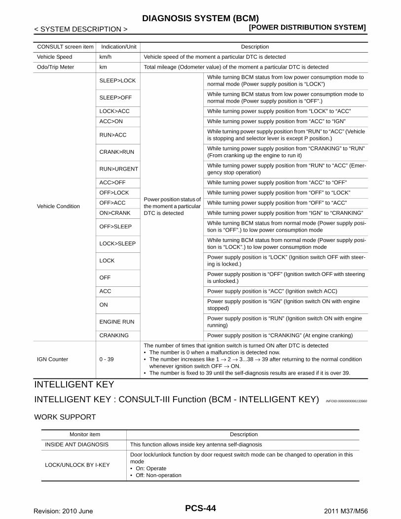
[POWER DISTRIBUTION SYSTEM]DIAGNOSIS SYSTEM (BCM)
< SYSTEM DESCRIPTION >
INTELLIGENT KEY
INTELLIGENT KEY : CONSULT-III Function (BCM - INTELLIGENT KEY) INFOID:0000000006133960
WORK SUPPORT
CONSULT screen item Indication/Unit Description
Vehicle Speed km/h Vehicle speed of the moment a particular DTC is detected
Odo/Trip Meter km Total mileage (Odometer value) of the moment a particular DTC is detected
Vehicle Condition
SLEEP>LOCK
Power position status of the moment a particular DTC is detected
While turning BCM status from low power consumption mode to normal mode (Power supply position is “LOCK”)
SLEEP>OFFWhile turning BCM status from low power consumption mode to normal mode (Power supply position is “OFF”.)
LOCK>ACC While turning power supply position from “LOCK” to “ACC”
ACC>ON While turning power supply position from “ACC” to “IGN”
RUN>ACCWhile turning power supply position from “RUN” to “ACC” (Vehicle is stopping and selector lever is except P position.)
CRANK>RUNWhile turning power supply position from “CRANKING” to “RUN” (From cranking up the engine to run it)
RUN>URGENTWhile turning power supply position from “RUN“ to “ACC” (Emer-gency stop operation)
ACC>OFF While turning power supply position from “ACC” to “OFF”
OFF>LOCK While turning power supply position from “OFF” to “LOCK”
OFF>ACC While turning power supply position from “OFF” to “ACC”
ON>CRANK While turning power supply position from “IGN” to “CRANKING”
OFF>SLEEPWhile turning BCM status from normal mode (Power supply posi-tion is “OFF”.) to low power consumption mode
LOCK>SLEEPWhile turning BCM status from normal mode (Power supply posi-tion is “LOCK”.) to low power consumption mode
LOCKPower supply position is “LOCK” (Ignition switch OFF with steer-ing is locked.)
OFFPower supply position is “OFF” (Ignition switch OFF with steering is unlocked.)
ACC Power supply position is “ACC” (Ignition switch ACC)
ONPower supply position is “IGN” (Ignition switch ON with engine stopped)
ENGINE RUNPower supply position is “RUN” (Ignition switch ON with engine running)
CRANKING Power supply position is “CRANKING” (At engine cranking)
IGN Counter 0 - 39
The number of times that ignition switch is turned ON after DTC is detected• The number is 0 when a malfunction is detected now.• The number increases like 1 → 2 → 3...38 → 39 after returning to the normal condition
whenever ignition switch OFF → ON.• The number is fixed to 39 until the self-diagnosis results are erased if it is over 39.
Monitor item Description
INSIDE ANT DIAGNOSIS This function allows inside key antenna self-diagnosis
LOCK/UNLOCK BY I-KEY
Door lock/unlock function by door request switch mode can be changed to operation in this mode• On: Operate• Off: Non-operation
PCS-44Revision: 2010 June 2011 M37/M56

CS
DIAGNOSIS SYSTEM (BCM)[POWER DISTRIBUTION SYSTEM]
C
D
E
F
G
H
I
J
K
L
B
A
O
P
N
P
< SYSTEM DESCRIPTION >
ENGINE START BY I-KEYEngine start function mode can be changed to operation with this mode • On: Operate• Off: Non-operation
TRUNK/GLASS HATCH OPEN
Buzzer reminder function mode by trunk lid opener request switch and Intelligent Key can be changed to operation with this mode• On: Operate• Off: Non-operation
PANIC ALARM SET
Panic alarm button pressing time on Intelligent Key remote control button can be selected from the following with this mode• MODE 1: 0.5 sec• MODE 2: Non-operation• MODE 3: 1.5 sec
TRUNK OPEN DELAY
Trunk button pressing on Intelligent Key can be selected as per the following in this mode.• MODE 1: Press and hold• MODE 2: Press twice• MODE 3: Press and hold, or press twice
LO- BATT OF KEY FOB WARNIntelligent Key low battery warning mode can be changed to operation with this mode • On: Operate• Off: Non-operation
ANTI KEY LOCK IN FUNCTIKey reminder function mode can be changed to operation with this mode• On: Operate• Off: Non-operation
HAZARD ANSWER BACK
Hazard reminder function mode by door request switch and Intelligent Key button can be se-lected from the following with this mode• Lock Only: Door lock operation only• Unlock Only: Door unlock operation only• Lock/Unlock: Lock and unlock operation• Off: Non-operation
ANS BACK I-KEY LOCK
Buzzer reminder function (lock operation) mode by door request switch can be selected from the following with this mode • Horn Chirp: Sound horn• Buzzer: Sound Intelligent Key warning buzzer• Off: Non-operation
ANS BACK I-KEY UNLOCK
Buzzer reminder function (unlock operation) mode by door request switch can be changed to operation with this mode• On: Operate• Off: Non-operation
SHORT CRANKING OUTPUT
Starter motor can operate during the times below• 70 msec• 100 msec• 200 msec
CONFIRM KEY FOB ID It can be checked whether Intelligent Key ID code is registered or not in this mode
AUTO LOCK SET
Auto door lock operation time can be changed in this mode• MODE 1: OFF• MODE 2: 30 sec• MODE 3: 1 minute• MODE 4: 2 minutes• MODE 5: 3 minutes• MODE 6: 4 minutes• MODE 7: 5 minutes
HORN WITH KEYLESS LOCK
Horn reminder function mode by Intelligent Key button can be selected from the following with this mode• On: Operate• Off: Non-operation
PW DOWN SET
Unlock button pressing time on Intelligent Key button can be selected from the following with this mode• MODE 1: 3 sec• MODE 2: Non-operation• MODE 3: 5 sec
Monitor item Description
PCS-45Revision: 2010 June 2011 M37/M56

[POWER DISTRIBUTION SYSTEM]DIAGNOSIS SYSTEM (BCM)
< SYSTEM DESCRIPTION >
SELF-DIAG RESULTRefer to BCS-55, "DTC Index".
DATA MONITOR
WELCOME LIGHT SELECT
Welcome light function mode can be selected from the following with this mode• Puddle/Outside Handle• Room lamp• Head & Tail Lamps (this item is displayed, but cannot be used)• Heart Beat
WELCOME LIGHT OP SETWelcome light function mode can be changed to operation with this mode• On: Operate• Off: Non-operation
INTELLIGENT KEY SETUPIntelligent Key interlock function mode can be changed to operation with this mode• On: Operate• Off: Non-operation
Monitor item Description
Monitor Item Condition
REQ SW -DR Indicates [On/Off] condition of door request switch (driver side)
REQ SW -AS Indicates [On/Off] condition of door request switch (passenger side)
REQ SW -BD/TR Indicates [On/Off] condition of trunk lid opener request switch
PUSH SW Indicates [On/Off] condition of push-button ignition switch
CLUTCH SWNOTE:This item is displayed, but cannot be monitored
BRAKE SW 1 Indicates [On/Off]* condition of stop lamp switch power supply
BRAKE SW 2 Indicates [On/Off] condition of stop lamp switch
DETE/CANCL SW Indicates [On/Off] condition of P position
SFT PN/N SW Indicates [On/Off] condition of P or N position
S/L -LOCK Indicates [On/Off] condition of steering lock unit (LOCK)
S/L -UNLOCK Indicates [On/Off] condition of steering lock unit (UNLOCK)
S/L RELAY -F/B Indicates [On/Off] condition of steering lock relay
UNLK SEN -DR Indicates [On/Off] condition of driver door UNLOCK status
PUSH SW -IPDM Indicates [On/Off] condition of push-button ignition switch
IGN RLY1 -F/B Indicates [On/Off] condition of ignition relay 1
DETE SW -IPDM Indicates [On/Off] condition of P position
SFT PN -IPDM Indicates [On/Off] condition of P or N position
SFT P -MET Indicates [On/Off] condition of P position
SFT N -MET Indicates [On/Off] condition of N position
ENGINE STATE Indicates [Stop/Stall/Crank/Run] condition of engine states
S/L LOCK-IPDM Indicates [On/Off] condition of steering lock unit (LOCK)
S/L UNLK-IPDM Indicates [On/Off] condition of steering lock unit (UNLOCK)
S/L RELAY-REQ Indicates [On/Off] condition of steering lock relay
VEH SPEED 1 Display the vehicle speed signal received from combination meter by numerical value [Km/h]
VEH SPEED 2 Display the vehicle speed signal received from ABS or VDC or TCM by numerical value [Km/h]
DOOR STAT-DR Indicates [LOCK/READY/UNLK] condition of driver side door status
DOOR STAT-AS Indicates [LOCK/READY/UNLK] condition of passenger side door status
ID OK FLAG Indicates [Set/Reset] condition of key ID
PRMT ENG STRT Indicates [Set/Reset] condition of engine start possibility
PCS-46Revision: 2010 June 2011 M37/M56

CS
DIAGNOSIS SYSTEM (BCM)[POWER DISTRIBUTION SYSTEM]
C
D
E
F
G
H
I
J
K
L
B
A
O
P
N
P
< SYSTEM DESCRIPTION >
*: OFF is displayed when brake pedal is depressed while brake switch power supply is OFF.
ACTIVE TEST
PRMT RKE STRTNOTE:This item is displayed, but cannot be monitored
TRNK/HAT MNTR Indicates [On/Off] condition of trunk room lamp switch
RKE-LOCK Indicates [On/Off] condition of LOCK signal from Intelligent Key
RKE-UNLOCK Indicates [On/Off] condition of UNLOCK signal from Intelligent Key
RKE-TR/BD Indicates [On/Off] condition of trunk open signal from Intelligent Key
RKE-PANIC Indicates [On/Off] condition of panic alarm button of Intelligent Key
RKE-MODE CHG Indicates [On/Off] condition of MODE CHANGE signal from Intelligent Key
RKE OPE COUN1When remote keyless entry receiver receives the signal transmitted while operating on Intelli-gent Key, the numerical value start changing
RKE OPE COUN2NOTE:This item is displayed, but cannot be monitored
Monitor Item Condition
Test item Description
BATTERY SAVERThis test is able to check interior room lamp operation• On: Operate• Off: Non-operation
OUTSIDE BUZZERThis test is able to check Intelligent Key warning buzzer operation• On: Operate• Off: Non-operation
INSIDE BUZZER
This test is able to check warning chime in combination meter operation• Take Out: Take away warning chime sounds when CONSULT-III screen is touched• Key: Key warning chime sounds when CONSULT-III screen is touched• Knob: OFF position warning chime sounds when CONSULT-III screen is touched• Off: Non-operation
INDICATOR
This test is able to check warning lamp operation• KEY ON: “KEY” Warning lamp illuminates when CONSULT-III screen is touched• KEY IND: “KEY” Warning lamp blinks when CONSULT-III screen is touched• Off: Non-operation
INT LAMPThis test is able to check interior room lamp operation• On: Operate• Off: Non-operation
LCD
This test is able to check meter display information• Engine start information displays when “BP N” on CONSULT-III screen is touched• Engine start information displays when “BP I” on CONSULT-III screen is touched• Key ID warning displays when “ID NG” on CONSULT-III screen is touched• Steering lock information displays when “ROTAT” on CONSULT-III screen is touched• P position warning displays when “SFT P” on CONSULT-III screen is touched• INSRT: This item is displayed, but cannot be monitored • BATT: This item is displayed, but cannot be monitored • Take away through window warning displays when “NO KY” on CONSULT-III screen is
touched• Take away warning display when “OUTKEY” on CONSULT-III screen is touched• OFF position warning display when “LK WN” on CONSULT-III screen is touched
FLASHERThis test is able to check hazard warning lamp operationThe hazard warning lamps are activated after “LH/RH/Off” on CONSULT-III screen is touched
P RANGEThis test is able to check AT shift selector power supply• On: Operate• Off: Non-operation
ENGINE SW ILLUMIThis test is able to check push-ignition switch illumination operationPush-ignition switch illumination illuminates when “ON” on CONSULT-III screen is touched
PCS-47Revision: 2010 June 2011 M37/M56
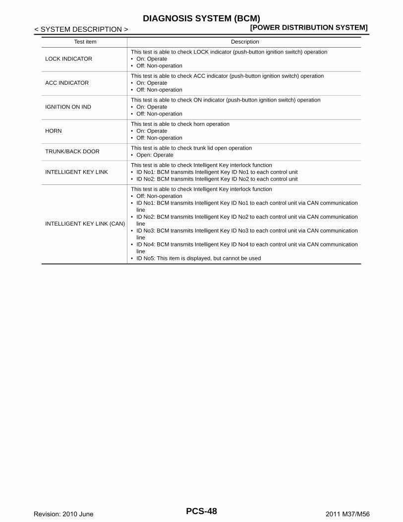
[POWER DISTRIBUTION SYSTEM]DIAGNOSIS SYSTEM (BCM)
< SYSTEM DESCRIPTION >
LOCK INDICATORThis test is able to check LOCK indicator (push-button ignition switch) operation• On: Operate• Off: Non-operation
ACC INDICATORThis test is able to check ACC indicator (push-button ignition switch) operation• On: Operate• Off: Non-operation
IGNITION ON INDThis test is able to check ON indicator (push-button ignition switch) operation• On: Operate• Off: Non-operation
HORNThis test is able to check horn operation• On: Operate• Off: Non-operation
TRUNK/BACK DOORThis test is able to check trunk lid open operation• Open: Operate
INTELLIGENT KEY LINKThis test is able to check Intelligent Key interlock function• ID No1: BCM transmits Intelligent Key ID No1 to each control unit• ID No2: BCM transmits Intelligent Key ID No2 to each control unit
INTELLIGENT KEY LINK (CAN)
This test is able to check Intelligent Key interlock function• Off: Non-operation• ID No1: BCM transmits Intelligent Key ID No1 to each control unit via CAN communication
line• ID No2: BCM transmits Intelligent Key ID No2 to each control unit via CAN communication
line• ID No3: BCM transmits Intelligent Key ID No3 to each control unit via CAN communication
line• ID No4: BCM transmits Intelligent Key ID No4 to each control unit via CAN communication
line• ID No5: This item is displayed, but cannot be used
Test item Description
PCS-48Revision: 2010 June 2011 M37/M56
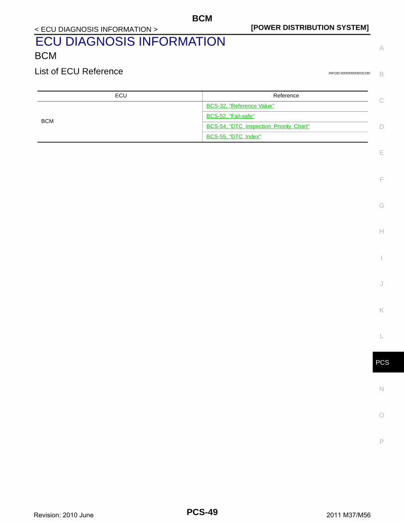
CS
BCM[POWER DISTRIBUTION SYSTEM]
C
D
E
F
G
H
I
J
K
L
B
A
O
P
N
P
< ECU DIAGNOSIS INFORMATION >
ECU DIAGNOSIS INFORMATIONBCM
List of ECU Reference INFOID:0000000006032180
ECU Reference
BCM
BCS-32, "Reference Value"
BCS-52, "Fail-safe"
BCS-54, "DTC Inspection Priority Chart"
BCS-55, "DTC Index"
PCS-49Revision: 2010 June 2011 M37/M56

[POWER DISTRIBUTION SYSTEM]POWER DISTRIBUTION SYSTEM
< WIRING DIAGRAM >
WIRING DIAGRAMPOWER DISTRIBUTION SYSTEM
Wiring Diagram INFOID:0000000006032181
JCMWA5571GB
PCS-50Revision: 2010 June 2011 M37/M56

CS
POWER DISTRIBUTION SYSTEM[POWER DISTRIBUTION SYSTEM]
C
D
E
F
G
H
I
J
K
L
B
A
O
P
N
P
< WIRING DIAGRAM >
JCMWA5572GB
PCS-51Revision: 2010 June 2011 M37/M56

[POWER DISTRIBUTION SYSTEM]POWER DISTRIBUTION SYSTEM
< WIRING DIAGRAM >
JCMWA5573GB
PCS-52Revision: 2010 June 2011 M37/M56

CS
POWER DISTRIBUTION SYSTEM[POWER DISTRIBUTION SYSTEM]
C
D
E
F
G
H
I
J
K
L
B
A
O
P
N
P
< WIRING DIAGRAM >
JCMWA5574GB
PCS-53Revision: 2010 June 2011 M37/M56

[POWER DISTRIBUTION SYSTEM]POWER DISTRIBUTION SYSTEM
< WIRING DIAGRAM >
JCMWA5575GB
PCS-54Revision: 2010 June 2011 M37/M56

CS
POWER DISTRIBUTION SYSTEM[POWER DISTRIBUTION SYSTEM]
C
D
E
F
G
H
I
J
K
L
B
A
O
P
N
P
< WIRING DIAGRAM >
JCMWA5576GB
PCS-55Revision: 2010 June 2011 M37/M56

[POWER DISTRIBUTION SYSTEM]POWER DISTRIBUTION SYSTEM
< WIRING DIAGRAM >
JCMWA5577GB
PCS-56Revision: 2010 June 2011 M37/M56

CS
POWER DISTRIBUTION SYSTEM[POWER DISTRIBUTION SYSTEM]
C
D
E
F
G
H
I
J
K
L
B
A
O
P
N
P
< WIRING DIAGRAM >
JCMWA5578GB
PCS-57Revision: 2010 June 2011 M37/M56
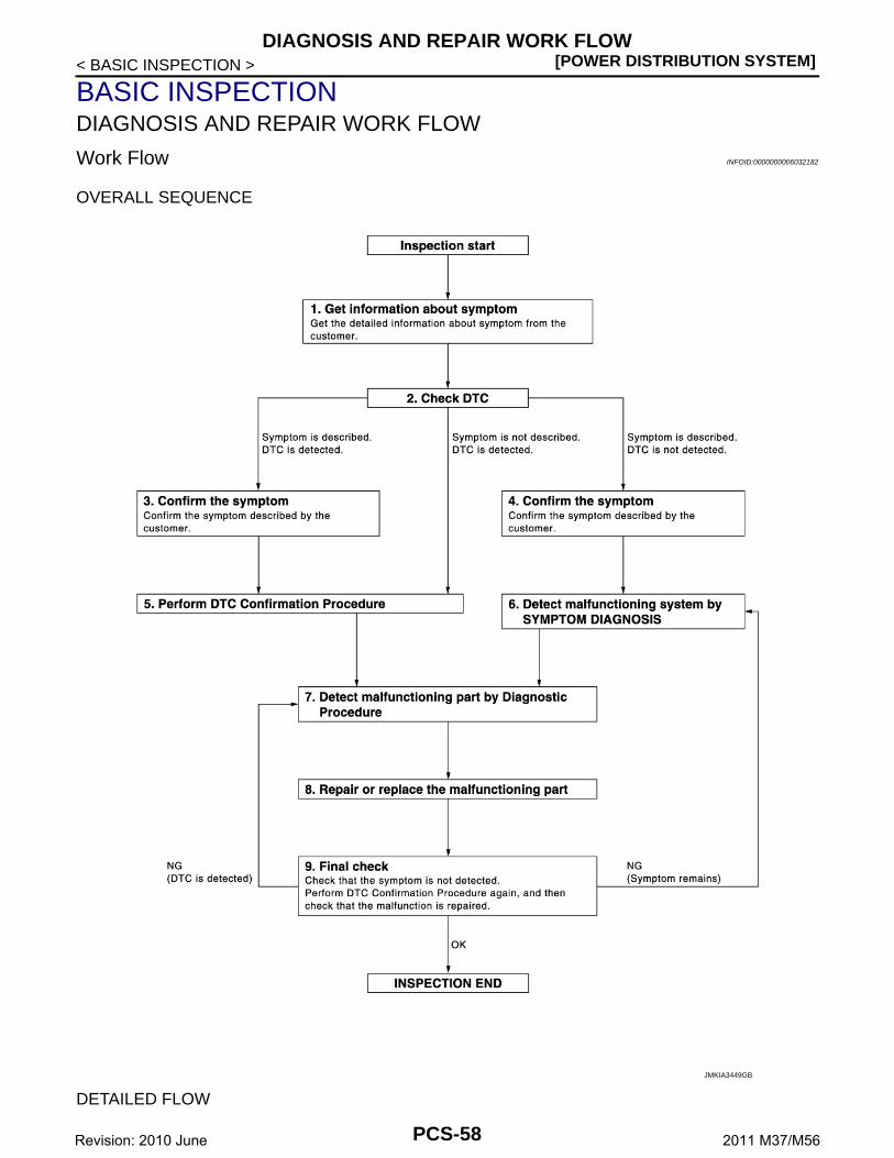
[POWER DISTRIBUTION SYSTEM]DIAGNOSIS AND REPAIR WORK FLOW
< BASIC INSPECTION >
BASIC INSPECTIONDIAGNOSIS AND REPAIR WORK FLOW
Work Flow INFOID:0000000006032182
OVERALL SEQUENCE
DETAILED FLOW
JMKIA3449GB
PCS-58Revision: 2010 June 2011 M37/M56

CS
DIAGNOSIS AND REPAIR WORK FLOW[POWER DISTRIBUTION SYSTEM]
C
D
E
F
G
H
I
J
K
L
B
A
O
P
N
P
< BASIC INSPECTION >
1.GET INFORMATION ABOUT SYMPTOM
Get detailed information from the customer about the symptom (the condition and the environment when theincident/malfunction occurs).
>> GO TO 2.
2.CHECK DTC
1. Check DTC for BCM and IPDM E/R.2. Perform the following procedure if DTC is displayed.- Record DTC and freeze frame data (Print them out with CONSULT-III.)- Erase DTC.- Study the relationship between the cause detected by DTC and the symptom described by the customer.3. Check related service bulletins for information.Are any symptoms described and any DTC detected?Symptom is described, DTC is displayed>>GO TO 3.Symptom is described, DTC is not displayed>>GO TO 4.Symptom is not described, DTC is displayed>>GO TO 5.
3.CONFIRM THE SYMPTOM
Confirm the symptom described by the customer.Connect CONSULT-III to the vehicle in the “DATA MONITOR” mode and check real time diagnosis results.Verify relation between the symptom and the condition when the symptom is detected.
>> GO TO 5.
4.CONFIRM THE SYMPTOM
Confirm the symptom described by the customer.Connect CONSULT-III to the vehicle in the “DATA MONITOR ” mode and check real time diagnosis results.Verify relation between the symptom and the condition when the symptom is detected.
>> GO TO 6.
5.PERFORM DTC CONFIRMATION PROCEDURE
Perform DTC Confirmation Procedure for the displayed DTC, and then check that DTC is detected again.At this time, always connect CONSULT-III to the vehicle, and check diagnostic results in real time.If two or more DTCs are detected, refer to BCS-54, "DTC Inspection Priority Chart", and determine troublediagnosis order.NOTE:Perform Component Function Check if DTC Confirmation Procedure is not included in Service Manual. Thissimplified check procedure is an effective alternative, although DTC cannot be detected during this check.If the result of Component Function Check is NG, it is the same as the detection of DTC by DTC ConfirmationProcedure.Is DTC detected?YES >> GO TO 7.NO >> Refer to GI-38, "Intermittent Incident".
6.DETECT MALFUNCTIONING SYSTEM BY SYMPTOM DIAGNOSIS
Detect malfunctioning system according to SYMPTOM DIAGNOSIS based on the confirmed symptom in step4, and determine the trouble diagnosis order based on possible causes and symptom.
>> GO TO 7.
7.DETECT MALFUNCTIONING PART BY DIAGNOSTIC PROCEDURE
Inspect according to Diagnostic Procedure of the system.NOTE:The Diagnostic Procedure described based on open circuit inspection. A short circuit inspection is alsorequired for the circuit check in the Diagnostic Procedure.
PCS-59Revision: 2010 June 2011 M37/M56

[POWER DISTRIBUTION SYSTEM]DIAGNOSIS AND REPAIR WORK FLOW
< BASIC INSPECTION >Is malfunctioning part detected?YES >> GO TO 8.NO >> Check voltage of related BCM terminals using CONSULT-III.
8.REPAIR OR REPLACE THE MALFUNCTIONING PART
1. Repair or replace the malfunctioning part.2. Reconnect parts or connectors disconnected during Diagnostic Procedure again after repair and replace-
ment.3. Check DTC. If DTC is displayed, erase it.
>> GO TO 9.
9.FINAL CHECK
When DTC was detected in step 2, perform DTC Confirmation Procedure or Component Function Checkagain, and then check that the malfunction is repaired securely.When symptom was described by the customer, refer to confirmed symptom in step 3 or 4, and check that thesymptom is not detected.Does the symptom reappear?YES (DTC is detected)>>GO TO 7.YES (Symptom remains)>>GO TO 6.NO >> INSPECTION END
PCS-60Revision: 2010 June 2011 M37/M56

CS
B2614 ACC RELAY CIRCUIT[POWER DISTRIBUTION SYSTEM]
C
D
E
F
G
H
I
J
K
L
B
A
O
P
N
P
< DTC/CIRCUIT DIAGNOSIS >
DTC/CIRCUIT DIAGNOSISB2614 ACC RELAY CIRCUIT
DTC Logic INFOID:0000000006032183
DTC DETECTION LOGIC
DTC CONFIRMATION PROCEDURE
1.PERFORM DTC CONFIRMATION PROCEDURE
1. Turn the power supply position to ACC under the following conditions, and wait for 2 second or more.- Selector lever is in the P position- Do not depress brake pedal2. Check “Self-diagnosis result” of BCM with CONSULT-III. Is DTC detected?YES >> Go to PCS-61, "Diagnosis Procedure".NO >> INSPECTION END
Diagnosis Procedure INFOID:0000000006032184
1.CHECK ACCESSORY RELAY POWER SUPPLY-1
1. Turn ignition switch OFF.2. Disconnect accessory relay.3. Check voltage between accessory relay harness connector and ground.
Is the inspection result normal?YES >> GO TO 3.NO >> GO TO 2.
2.CHECK ACCESSORY RELAY POWER SUPPLY CIRCUIT
1. Turn ignition switch OFF.2. Disconnect BCM connector.3. Check continuity between accessory relay harness connector and BCM harness connector.
4. Check continuity between accessory relay harness connector and ground.
DTC No.Trouble diagnosis
nameDTC detecting condition Possible cause
B2614 BCMAn immediate operation of accessory relay is re-quested by BCM, but there is no response for more than 2 second.
• Harness or connectors(Accessory relay circuit is open or shorted)
• BCM• Accessory relay
(+)
(–) ConditionVoltage (V)(Approx.)
Accessory relay
Terminal
1 Ground Ignition switchOFF 0
ACC or ON 12
Accessory relay BCMContinuity
Terminal Connector Terminal
1 M123 96 Existed
PCS-61Revision: 2010 June 2011 M37/M56

[POWER DISTRIBUTION SYSTEM]B2614 ACC RELAY CIRCUIT
< DTC/CIRCUIT DIAGNOSIS >
Is the inspection result normal?YES >> Replace BCM. Refer to BCS-79, "Removal and Installation".NO >> Repair or replace harness.
3.CHECK ACCESSORY RELAY GROUND CIRCUIT
1. Turn ignition switch OFF.2. Check continuity between accessory relay harness connector and ground.
Is the inspection result normal?YES >> GO TO 4.NO >> Repair accessory relay ground circuit.
4.CHECK ACCESSORY RELAY POWER SUPPLY CIRCUIT-2
1. Turn ignition switch ACC.2. Check voltage between accessory relay harness connector and ground.
Is the inspection result normal?YES >> GO TO 5.NO >> Check continuity open or short between accessory relay and battery.
5.CHECK ACCESSORY RELAY
Refer to PCS-62, "Component Inspection".Is the inspection result normal?YES >> GO TO 6.NO >> Replace accessory relay.
6.CHECK INTERMITTENT INCIDENT
Refer to GI-38, "Intermittent Incident".
>> INSPECTION END
Component Inspection INFOID:0000000006032185
1.CHECK ACCESSORY RELAY
1. Turn ignition switch OFF.2. Remove accessory relay.
Accessory relay
GroundContinuity
Terminal
1 Not existed
Accessory relay
GroundContinuity
Terminal
2 Existed
(+)
(–)Voltage (V)(Approx.)
Accessory relay
Terminal
5 Ground Battery voltage
PCS-62Revision: 2010 June 2011 M37/M56

CS
B2614 ACC RELAY CIRCUIT[POWER DISTRIBUTION SYSTEM]
C
D
E
F
G
H
I
J
K
L
B
A
O
P
N
P
< DTC/CIRCUIT DIAGNOSIS >3. Check the continuity between accessory relay terminals.
Is the inspection result normal?YES >> INSPECTION ENDNO >> Replace accessory relay
Terminals Condition Continuity
3 and 512 V direct current supply between terminals 1 and 2 Existed
No current supply Not existed
PBIB0098E
PCS-63Revision: 2010 June 2011 M37/M56

[POWER DISTRIBUTION SYSTEM]B2615 BLOWER RELAY CIRCUIT
< DTC/CIRCUIT DIAGNOSIS >
B2615 BLOWER RELAY CIRCUIT
DTC Logic INFOID:0000000006032186
DTC DETECTION LOGIC
DTC CONFIRMATION PROCEDURE
1.PERFORM DTC CONFIRMATION PROCEDURE
1. Turn ignition switch ON under the following conditions, and wait for 1 second or more.- Selector lever is in the P position- Do not depress brake pedal2. Check “Self-diagnosis result” of BCM with CONSULT-III. Is DTC detected?YES >> Go to PCS-64, "Diagnosis Procedure".NO >> INSPECTION END
Diagnosis Procedure INFOID:0000000006032187
1.CHECK BLOWER RELAY POWER SUPPLY
1. Turn ignition switch OFF.2. Disconnect blower relay.3. Check voltage between blower relay harness connector and ground.
Is the inspection result normal?YES >> GO TO 3.NO >> GO TO 2.
2.CHECK BLOWER RELAY POWER SUPPLY CIRCUIT
1. Turn ignition switch OFF.2. Disconnect BCM connector.3. Check continuity between blower relay harness connector and BCM harness connector.
4. Check continuity between blower relay harness connector and ground.
Is the inspection result normal?
DTC No.Trouble diagnosis
nameDTC detecting condition Possible cause
B2615 BCM
BCM detects a difference of signal for 1 second or more between the following items.• Blower relay ON/OFF request • Blower relay feedback
• Harness or connectors (Blower relay circuit is open or shorted)
• BCM• Blower relay
(+)
(–) ConditionVoltage (V)(Approx.)
Blower relay
Terminal
1 Ground Ignition switchOFF or ACC 0
ON Battery voltage
Blower relay BCMContinuity
Terminal Connector Terminal
1 M123 106 Existed
Blower relay
GroundContinuity
Terminal
1 Not existed
PCS-64Revision: 2010 June 2011 M37/M56

CS
B2615 BLOWER RELAY CIRCUIT[POWER DISTRIBUTION SYSTEM]
C
D
E
F
G
H
I
J
K
L
B
A
O
P
N
P
< DTC/CIRCUIT DIAGNOSIS >YES >> GO TO 6.NO >> Repair or replace harness.
3.CHECK BLOWER RELAY GROUND CIRCUIT
1. Turn ignition switch OFF.2. Check continuity between blower relay harness connector and ground.
Is the inspection result normal?YES >> GO TO 4.NO >> Repair blower relay ground circuit.
4.CHECK BLOWER RELAY POWER SUPPLY CIRCUIT-2
1. Turn ignition switch ON.2. Check voltage between blower relay harness connector and ground.
Is the inspection result normal?YES >> GO TO 5.NO >> Check continuity open or short between blower relay and battery.
5.CHECK BLOWER RELAY
Refer to PCS-65, "Component Inspection".Is the inspection result normal?YES >> GO TO 6.NO >> Replace blower relay.
6.CHECK INTERMITTENT INCIDENT
Refer to GI-38, "Intermittent Incident".
>> INSPECTION END
Component Inspection INFOID:0000000006032188
1.CHECK BLOWER RELAY
1. Turn ignition switch OFF.2. Remove blower relay.3. Check the continuity between blower relay terminals.
Is the inspection result normal?YES >> INSPECTION ENDNO >> Replace blower relay
Blower relay
GroundContinuity
Terminal
2 Existed
(+)
(–)Voltage (V)(Approx.)
Blower relay
Terminal
5 Ground Battery voltage
Terminals Condition Continuity
3 and 512 V direct current supply between terminals 1 and 2 Existed
No current supply Not existed
PBIB0098E
PCS-65Revision: 2010 June 2011 M37/M56

[POWER DISTRIBUTION SYSTEM]B2616 IGNITION RELAY CIRCUIT
< DTC/CIRCUIT DIAGNOSIS >
B2616 IGNITION RELAY CIRCUIT
DTC Logic INFOID:0000000006032189
DTC DETECTION LOGIC
DTC CONFIRMATION PROCEDURE
1.PERFORM DTC CONFIRMATION PROCEDURE
1. Turn ignition switch ON under the following conditions, and wait for 1 second or more.- Selector lever is in the P position- Do not depress brake pedal2. Check “Self-diagnosis result” with CONSULT-III. Is DTC detected?YES >> Go to PCS-66, "Diagnosis Procedure".NO >> INSPECTION END
Diagnosis Procedure INFOID:0000000006032190
1.CHECK IGNITION RELAY POWER SUPPLY
1. Turn ignition switch OFF.2. Disconnect ignition relay.3. Check voltage between ignition relay harness connector and ground.
Is the inspection result normal?YES >> GO TO 3.NO >> GO TO 2.
2.CHECK IGNITION RELAY POWER SUPPLY CIRCUIT
1. Turn ignition switch OFF.2. Disconnect BCM connector.3. Check continuity between ignition relay harness connector and BCM harness connector.
4. Check continuity between ignition relay harness connector and ground.
Is the inspection result normal?
DTC No.Trouble diagnosis
nameDTC detecting condition Possible cause
B2616 BCMAn immediate operation of ignition relay is request-ed by BCM, but there is no response for more than 1 second
• Harness or connectors (Ignition relay circuit is open or shorted)
• BCM• Ignition relay
(+)
(–) ConditionVoltage (V)(Approx.)
Ignition relay
Terminal
2 Ground Ignition switchOFF or ACC 0
ON Battery voltage
Ignition relay BCMContinuity
Terminal Connector Terminal
2 M123 99 Existed
Ignition relay
GroundContinuity
Terminal
2 Not existed
PCS-66Revision: 2010 June 2011 M37/M56

CS
B2616 IGNITION RELAY CIRCUIT[POWER DISTRIBUTION SYSTEM]
C
D
E
F
G
H
I
J
K
L
B
A
O
P
N
P
< DTC/CIRCUIT DIAGNOSIS >YES >> Replace BCM. Refer to BCS-79, "Removal and Installation".NO >> Repair or replace harness.
3.CHECK IGNITION RELAY GROUND CIRCUIT
1. Turn ignition switch OFF.2. Check continuity between ignition relay harness connector and ground.
Is the inspection result normal?YES >> GO TO 4.NO >> Repair ignition relay ground circuit.
4.CHECK IGNITION RELAY POWER SUPPLY CIRCUIT-2
1. Turn ignition switch ON.2. Check voltage between ignition relay harness connector and ground.
Is the inspection result normal?YES >> GO TO 5.NO >> Check continuity open or short between ignition relay and battery.
5.CHECK IGNITION RELAY
Refer to PCS-67, "Component Inspection".Is the inspection result normal?YES >> GO TO 6.NO >> Replace ignition relay.
6.CHECK INTERMITTENT INCIDENT
Refer to GI-38, "Intermittent Incident".
>> INSPECTION END
Component Inspection INFOID:0000000006032191
1.CHECK IGNITION RELAY
1. Turn ignition switch OFF.2. Remove ignition relay.3. Check the continuity between ignition relay terminals.
Is the inspection result normal?YES >> INSPECTION ENDNO >> Replace Ignition relay
Ignition relay
GroundContinuity
Terminal
1 Existed
(+)
(–)Voltage (V)(Approx.)
Ignition relay
Terminal
5 Ground Battery voltage
Terminals Condition Continuity
3 and 512 V direct current supply between terminals 1 and 2 Existed
No current supply Not existed
PBIB0098E
PCS-67Revision: 2010 June 2011 M37/M56

[POWER DISTRIBUTION SYSTEM]B2618 BCM
< DTC/CIRCUIT DIAGNOSIS >
B2618 BCM
DTC Logic INFOID:0000000006032192
DTC DETECTION LOGICNOTE:• If DTC B2618 is displayed with DTC U1000, first perform the trouble diagnosis for DTC U1000. Refer to
BCS-68, "DTC Logic".• If DTC B2618 is displayed with DTC U1010, first perform the trouble diagnosis for DTC U1010. Refer to
BCS-69, "DTC Logic".
DTC CONFIRMATION PROCEDURE
1.PERFORM DTC CONFIRMATION PROCEDURE
1. Turn ignition switch ON under the following conditions, and wait for 1 second or more.- Selector lever is in the P or N position- Do not depress brake pedal2. Check “Self-diagnosis result” of BCM with CONSULT-III. Is DTC detected?YES >> Go to PCS-68, "Diagnosis Procedure".NO >> INSPECTION END
Diagnosis Procedure INFOID:0000000006032193
1.INSPECTION START
1. Turn ignition switch ON.2. Select “Self-diagnosis result” of BCM with CONSULT-III.3. Touch “ERASE”.4. Perform DTC Confirmation Procedure.
See PCS-68, "DTC Logic".Is the 1st trip DTC B2618 displayed again?YES >> Replace BCM. Refer to BCS-79, "Removal and Installation"NO >> INSPECTION END
DTC No.Trouble diagnosis
nameDTC detecting condition Possible cause
B2618 BCMAn immediate operation of ignition relay (IPDM E/R) is re-quested by BCM, but there is no response for more than 1 second
BCM
PCS-68Revision: 2010 June 2011 M37/M56

CS
B261A PUSH-BUTTON IGNITION SWITCH[POWER DISTRIBUTION SYSTEM]
C
D
E
F
G
H
I
J
K
L
B
A
O
P
N
P
< DTC/CIRCUIT DIAGNOSIS >
B261A PUSH-BUTTON IGNITION SWITCH
DTC Logic INFOID:0000000006032194
DTC DETECTION LOGICNOTE:• If DTC B261A is displayed with DTC U1000, first perform the trouble diagnosis for DTC U1000. Refer to
BCS-68, "DTC Logic".• If DTC B261A is displayed with DTC U1010, first perform the trouble diagnosis for DTC U1010. Refer to
BCS-69, "DTC Logic".
DTC CONFIRMATION PROCEDURE
1.PERFORM DTC CONFIRMATION PROCEDURE
1. Press the push-button ignition switch under the following conditions, and wait for 1 second or more.- Selector lever is in the P or N position- Do not depress brake pedal2. Check “Self-diagnosis result” of BCM with CONSULT-III. Is DTC detected?YES >> Go to PCS-69, "Diagnosis Procedure".NO >> INSPECTION END
Diagnosis Procedure INFOID:0000000006032195
1.CHECK IGNITION SWITCH OUTPUT SIGNAL (PUSH-BUTTON IGNITION SWITCH)
1. Disconnect push-button ignition switch connector and IPDM E/R connector.2. Check voltage between push-button ignition switch harness connector and ground.
Is the inspection result normal?YES >> GO TO 3.NO >> GO TO 2.
2.CHECK PUSH-BUTTON IGNITION SWITCH CIRCUIT (BCM)
1. Disconnect BCM connector.2. Check continuity between BCM harness connector and push-button ignition switch harness connector.
3. Check continuity between push-button ignition switch harness connector and ground.
DTC No.Trouble diagnosis
nameDTC detecting condition Possible cause
B261A PUSH-BTN IGN SW
BCM detects a difference of signal for 1 second or more between the following items. • Push-button ignition switch signal• Push-button ignition switch status signal (CAN)
• Harness or connectors(Push-button ignition switch circuit is open or shorted.)
• BCM• IPDM E/R
(+)
(–)Voltage (V)(Approx.)
Push-button ignition switch
Connector Terminal
M50 4 Ground 12
BCM Push-button ignition switchContinuity
Connector Terminal Connector Terminal
M123 100 M50 4 Existed
Push-button ignition switch
GroundContinuity
Connector Terminal
M50 4 Not existed
PCS-69Revision: 2010 June 2011 M37/M56

[POWER DISTRIBUTION SYSTEM]B261A PUSH-BUTTON IGNITION SWITCH
< DTC/CIRCUIT DIAGNOSIS >Is the inspection result normal?YES >> Replace BCM. Refer to BCS-79, "Removal and Installation".NO >> Repair or replace harness.
3.CHECK IGNITION SWITCH OUTPUT SIGNAL (IPDM E/R)
Check voltage between IPDM E/R harness connector and ground.
Is the inspection result normal?YES >> Replace IPDM E/R.NO >> GO TO 4.
4.CHECK PUSH-BUTTON IGNITION SWITCH CIRCUIT (IPDM E/R)
1. Disconnect IPDM E/R connector.2. Check continuity between IPDM E/R harness connector and push-button ignition switch harness connec-
tor.
3. Check continuity between push-button ignition switch harness connector and ground.
Is the inspection result normal?YES >> GO TO 5.NO >> Repair or replace harness.
5.CHECK INTERMITTENT INCIDENT
Refer to GI-38, "Intermittent Incident".
>> INSPECTION END
(+)
(–)Voltage (V)(Approx.)
IPDM E/R
Connector Terminal
E5 30 Ground 12
IPDM E/R Push-button ignition switchContinuity
Connector Terminal Connector Terminal
E5 30 M50 4 Existed
Push-button ignition switch
GroundContinuity
Connector Terminal
M50 4 Not existed
PCS-70Revision: 2010 June 2011 M37/M56

CS
B26F1 IGNITION RELAY[POWER DISTRIBUTION SYSTEM]
C
D
E
F
G
H
I
J
K
L
B
A
O
P
N
P
< DTC/CIRCUIT DIAGNOSIS >
B26F1 IGNITION RELAY
DTC Logic INFOID:0000000006032196
DTC DETECTION LOGIC
DTC CONFIRMATION PROCEDURE
1.PERFORM DTC CONFIRMATION PROCEDURE
1. Turn ignition switch ON under the following conditions, and wait for 2 seconds or more.- Selector lever is in the P or N position- Do not depress brake pedal2. Check “Self-diagnosis result” with CONSULT-III. Is DTC detected?YES >> Go to PCS-71, "Diagnosis Procedure".NO >> INSPECTION END
Diagnosis Procedure INFOID:0000000006032197
1.CHECK IPDM E/R SELF-DIAGNOSTIC RESULT
1. Turn ignition switch ON.2. Erase the DTC of IPDM E/R.3. Turn ignition switch OFF.4. Turn ignition switch ON and check the DTC again.Is DTC detected?YES >> Repair or replace the malfunctioning part. Refer to PCS-24, "DTC Index".NO >> GO TO 2.
2.CHECK IGNITION RELAY (IPDM E/R) CONTROL SIGNAL
Check voltage between BCM harness connector and ground.
Is the inspection result normal?YES >> GO TO 3.NO >> Replace BCM. Refer to BCS-79, "Removal and Installation".
3.CHECK IGNITION RELAY (IPDM E/R) CONTROL SIGNAL CIRCUIT
1. Turn ignition switch OFF.2. Disconnect BCM and IPDM connectors.3. Check continuity between BCM harness connector and IPDM E/R harness connector.
Is the inspection result normal?YES >> Replace IPDM E/R.
DTC No.Trouble diagnosis
nameDTC detecting condition Possible cause
B26F1 IGN RELAY OFF
BCM transmits the ignition relay control signal (ON: 0 V) or ignition switch ON signal (ON) (CAN), but does not receives ignition switch ON signal (ON) (CAN) from IPDM E/R.
• Harness or connectors(ignition relay circuit is open)
• BCM• IPDM E/R
(+)
(–) ConditionVoltage (V)(Approx.)
BCM
Connector Terminal
M123 98 Ground Ignition switch ON 0
BCM IPDM E/RContinuity
Connector Terminal Connector Terminal
M123 98 E5 18 Existed
PCS-71Revision: 2010 June 2011 M37/M56

[POWER DISTRIBUTION SYSTEM]B26F1 IGNITION RELAY
< DTC/CIRCUIT DIAGNOSIS >NO >> Repair or replace harness.
PCS-72Revision: 2010 June 2011 M37/M56

CS
B26F2 IGNITION RELAY[POWER DISTRIBUTION SYSTEM]
C
D
E
F
G
H
I
J
K
L
B
A
O
P
N
P
< DTC/CIRCUIT DIAGNOSIS >
B26F2 IGNITION RELAY
DTC Logic INFOID:0000000006032198
DTC DETECTION LOGIC
DTC CONFIRMATION PROCEDURE
1.PERFORM DTC CONFIRMATION PROCEDURE
1. Turn ignition switch ON under the following conditions, and wait for 2 seconds or more.- Selector lever is in the P or N position- Do not depress brake pedal2. Check “Self-diagnosis result” with CONSULT-III. Is DTC detected?YES >> Go to PCS-73, "Diagnosis Procedure".NO >> INSPECTION END
Diagnosis Procedure INFOID:0000000006032199
1.CHECK IPDM E/R SELF-DIAGNOSTIC RESULT
1. Turn ignition switch ON.2. Erase the DTC of IPDM E/R.3. Turn ignition switch OFF.4. Turn ignition switch ON and check the DTC again.Is DTC detected?YES >> Repair or replace the malfunctioning part. Refer to PCS-24, "DTC Index".NO >> GO TO 2.
2.CHECK IGNITION RELAY (IPDM E/R) CONTROL SIGNAL
1. Turn ignition switch OFF.2. Check voltage between IPDM E/R harness connector and ground.
Is the inspection result normal?YES >> Replace IPDM E/R.NO >> GO TO 3.
3.CHECK IGNITION RELAY (IPDM E/R) CONTROL SIGNAL CIRCUIT - 1
1. Disconnect BCM and IPDM E/R connectors.2. Check continuity between IPDM E/R harness connector and ground.
Is the inspection result normal?YES >> GO TO 4.
DTC No.Trouble diagnosis
nameDTC detecting condition Possible cause
B26F2 IGN RELAY ON
BCM transmits the ignition relay control signal (OFF: 12 V) or ignition switch ON signal (OFF) (CAN), but does not receives ignition switch ON signal (OFF) (CAN) from IPDM E/R.
• Harness or connectors(ignition relay circuit is short)
• BCM• IPDM E/R
(+)
(–) ConditionVoltage (V)(Approx.)
IPDM E/R
Connector Terminal
E5 18 Ground Ignition switch OFF or ACC 12
IPDM E/R
GroundContinuity
Connector Terminal
E5 18 Not existed
PCS-73Revision: 2010 June 2011 M37/M56
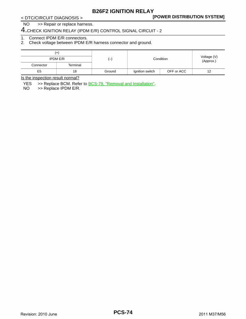
[POWER DISTRIBUTION SYSTEM]B26F2 IGNITION RELAY
< DTC/CIRCUIT DIAGNOSIS >NO >> Repair or replace harness.
4.CHECK IGNITION RELAY (IPDM E/R) CONTROL SIGNAL CIRCUIT - 2
1. Connect IPDM E/R connectors.2. Check voltage between IPDM E/R harness connector and ground.
Is the inspection result normal?YES >> Replace BCM. Refer to BCS-79, "Removal and Installation".NO >> Replace IPDM E/R.
(+)
(–) ConditionVoltage (V)(Approx.)
IPDM E/R
Connector Terminal
E5 18 Ground Ignition switch OFF or ACC 12
PCS-74Revision: 2010 June 2011 M37/M56

CS
B26F6 BCM[POWER DISTRIBUTION SYSTEM]
C
D
E
F
G
H
I
J
K
L
B
A
O
P
N
P
< DTC/CIRCUIT DIAGNOSIS >
B26F6 BCM
DTC Logic INFOID:0000000006032200
DTC DETECTION LOGICNOTE:• If DTC B26F6 is displayed with DTC U1000, first perform the trouble diagnosis for DTC U1000. Refer to
BCS-68, "DTC Logic".• If DTC B26F6 is displayed with DTC U1010, first perform the trouble diagnosis for DTC U1010. Refer to
BCS-69, "DTC Logic".
DTC CONFIRMATION PROCEDURE
1.PERFORM DTC CONFIRMATION PROCEDURE
1. Turn ignition switch ON under the following conditions, and wait for 1 second or more.- Selector lever is in the P or N position- Do not depress brake pedal2. Check “Self-diagnosis result” of BCM with CONSULT-III. Is DTC detected?YES >> Go to PCS-75, "Diagnosis Procedure".NO >> INSPECTION END
Diagnosis Procedure INFOID:0000000006032201
1.INSPECTION START
1. Turn ignition switch ON.2. Select “Self-diagnosis result” of BCM with CONSULT-III.3. Touch “ERASE”.4. Perform DTC Confirmation Procedure.
See PCS-75, "DTC Logic".Is DTC detected?YES >> Replace BCM. Refer to BCS-79, "Removal and Installation"NO >> INSPECTION END
DTC No.Trouble diagnosis
nameDTC detecting condition Possible cause
B26F6 BCMIgnition relay ON signal is not transmitted from IPDM E/R when BCM turns ignition relay ON.
BCM
PCS-75Revision: 2010 June 2011 M37/M56

[POWER DISTRIBUTION SYSTEM]PUSH-BUTTON IGNITION SWITCH
< DTC/CIRCUIT DIAGNOSIS >
PUSH-BUTTON IGNITION SWITCH
Component Function Check INFOID:0000000006032204
1.CHECK FUNCTION
1. Select “PUSH SW” in “Data Monitor” mode with CONSULT-III. 2. Check the push-button ignition switch signal under the following conditions.
Is the indication normal?YES >> INSPECTION END.NO >> Go to PCS-76, "Diagnosis Procedure".
Diagnosis Procedure INFOID:0000000006032205
1.CHECK PUSH-BUTTON IGNITION SWITCH OUTPUT SIGNAL 1
1. Turn ignition switch OFF.2. Disconnect push-button ignition switch connector and IPDM E/R connector.3. Check voltage between push-button ignition switch harness connector and ground.
Is the inspection result normal?YES >> GO TO 3.NO >> GO TO 2.
2.CHECK PUSH-BUTTON IGNITION SWITCH CIRCUIT 1
1. Disconnect BCM connector.2. Check continuity between BCM harness connector and push-button ignition switch harness connector.
3. Check continuity between BCM harness connector and ground.
Is the inspection result normal?YES >> Replace BCM. Refer to BCS-79, "Removal and Installation".NO >> Repair or replace harness.
3.CHECK PUSH-BUTTON IGNITION SWITCH OUTPUT SIGNAL 2
Check voltage between IPDM E/R harness connector and ground.
Test item Condition Status
PUSH SWPush-button ignition switch is pressed ON
Push-button ignition switch is not pressed OFF
(+)
(–)Voltage (V)(Approx.)
Push-button ignition switch
Connector Terminal
M50 4 Ground Battery voltage
BCM Push-button ignition switchContinuity
Connector Terminal Connector Terminal
M123 100 M50 4 Existed
BCM
GroundContinuity
Connector Terminal
M123 100 Not existed
PCS-76Revision: 2010 June 2011 M37/M56

CS
PUSH-BUTTON IGNITION SWITCH[POWER DISTRIBUTION SYSTEM]
C
D
E
F
G
H
I
J
K
L
B
A
O
P
N
P
< DTC/CIRCUIT DIAGNOSIS >
Is the inspection result normal?YES >> GO TO 5.NO >> GO TO 4.
4.CHECK PUSH-BUTTON IGNITION SWITCH CIRCUIT 2
1. Disconnect BCM connector.2. Check continuity between IPDM E/R harness connector and push-button ignition switch harness connec-
tor.
3. Check continuity between IPDM E/R harness connector and ground.
Is the inspection result normal?YES >> Replace IPDM E/R.NO >> Repair or replace harness.
5.CHECK PUSH-BUTTON IGNITION SWITCH GROUND CIRCUIT
Check continuity between push-button ignition switch harness connector and ground.
Is the inspection result normal?YES >> GO TO 6.NO >> Repair or replace harness.
6.CHECK PUSH-BUTTON IGNITION SWITCH
Refer to PCS-77, "Component Inspection".Is the inspection result normal?YES >> GO TO 7.NO >> Replace push-button ignition switch.
7.CHECK INTERMITTENT INCIDENT
Refer to GI-38, "Intermittent Incident".
>> INSPECTION END
Component Inspection INFOID:0000000006032206
1.CHECK PUSH-BUTTON IGNITION SWITCH
1. Turn ignition switch OFF.2. Disconnect push-button ignition switch connector.3. Check continuity between push-button ignition switch terminals.
(+)
(–)Voltage (V)(Approx.)
IPDM E/R
Connector Terminal
E5 30 Ground Battery voltage
IPDM E/R Push-button ignition switchContinuity
Connector Terminal Connector Terminal
E5 30 M50 4 Existed
IPDM E/R
GroundContinuity
Connector Terminal
E5 30 Not existed
Push-button ignition switch
GroundContinuity
Connector Terminal
M50 1 Existed
PCS-77Revision: 2010 June 2011 M37/M56

[POWER DISTRIBUTION SYSTEM]PUSH-BUTTON IGNITION SWITCH
< DTC/CIRCUIT DIAGNOSIS >
Is the inspection result normal?YES >> INSPECTION ENDNO >> Replace push-button ignition switch.
Push-button ignition switchCondition Continuity
Terminal
4 1Pressed Existed
Not pressed Not existed
PCS-78Revision: 2010 June 2011 M37/M56
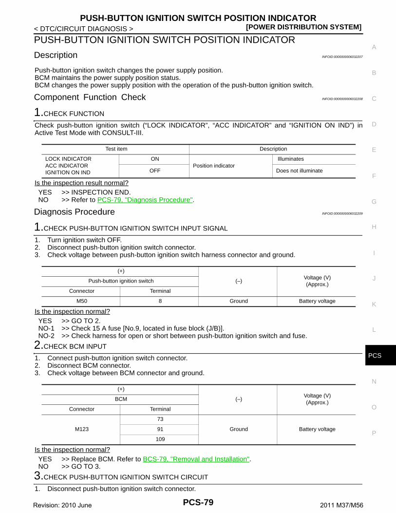
CS
PUSH-BUTTON IGNITION SWITCH POSITION INDICATOR[POWER DISTRIBUTION SYSTEM]
C
D
E
F
G
H
I
J
K
L
B
A
O
P
N
P
< DTC/CIRCUIT DIAGNOSIS >
PUSH-BUTTON IGNITION SWITCH POSITION INDICATOR
Description INFOID:0000000006032207
Push-button ignition switch changes the power supply position.BCM maintains the power supply position status.BCM changes the power supply position with the operation of the push-button ignition switch.
Component Function Check INFOID:0000000006032208
1.CHECK FUNCTION
Check push-button ignition switch (“LOCK INDICATOR”, “ACC INDICATOR” and “IGNITION ON IND”) inActive Test Mode with CONSULT-III.
Is the inspection result normal?YES >> INSPECTION END.NO >> Refer to PCS-79, "Diagnosis Procedure".
Diagnosis Procedure INFOID:0000000006032209
1.CHECK PUSH-BUTTON IGNITION SWITCH INPUT SIGNAL
1. Turn ignition switch OFF.2. Disconnect push-button ignition switch connector.3. Check voltage between push-button ignition switch harness connector and ground.
Is the inspection normal?YES >> GO TO 2.NO-1 >> Check 15 A fuse [No.9, located in fuse block (J/B)].NO-2 >> Check harness for open or short between push-button ignition switch and fuse.
2.CHECK BCM INPUT
1. Connect push-button ignition switch connector.2. Disconnect BCM connector.3. Check voltage between BCM connector and ground.
Is the inspection normal?YES >> Replace BCM. Refer to BCS-79, "Removal and Installation".NO >> GO TO 3.
3.CHECK PUSH-BUTTON IGNITION SWITCH CIRCUIT
1. Disconnect push-button ignition switch connector.
Test item Description
LOCK INDICATORACC INDICATORIGNITION ON IND
ONPosition indicator
Illuminates
OFF Does not illuminate
(+)
(–)Voltage (V)(Approx.)
Push-button ignition switch
Connector Terminal
M50 8 Ground Battery voltage
(+)
(–)Voltage (V)(Approx.)
BCM
Connector Terminal
M123
73
Ground Battery voltage91
109
PCS-79Revision: 2010 June 2011 M37/M56

[POWER DISTRIBUTION SYSTEM]PUSH-BUTTON IGNITION SWITCH POSITION INDICATOR
< DTC/CIRCUIT DIAGNOSIS >2. Check continuity between BCM harness connector and push-button ignition switch harness connector.
3. Check continuity between BCM harness connector and ground.
Is the inspection normal?YES >> Replace push-button ignition switch.NO >> Repair or replace harness.
IndicatorBCM Push-button ignition switch
ContinuityConnector Terminal Connector Terminal
LOCK
M123
91
M50
5
ExistedACC 109 6
ON 73 7
IndicatorBCM
Ground
ContinuityConnector Terminal
LOCK
M123
91
Not existedACC 109
ON 73
PCS-80Revision: 2010 June 2011 M37/M56

CS
PUSH-BUTTON IGNITION SWITCH DOES NOT OPERATE[POWER DISTRIBUTION SYSTEM]
C
D
E
F
G
H
I
J
K
L
B
A
O
P
N
P
< SYMPTOM DIAGNOSIS >
SYMPTOM DIAGNOSISPUSH-BUTTON IGNITION SWITCH DOES NOT OPERATE
Description INFOID:0000000006032210
Check that vehicle is under the condition shown in “Conditions of vehicle” before starting diagnosis, and checkeach symptom.NOTE:The engine start function, door lock function, power distribution system, and NATS-IVIS/NVIS in the IntelligentKey system are closely related to each other regarding control. The vehicle security function can operate onlywhen the door lock and power distribution system are operating normally.
Conditions of Vehicle (Operating Conditions)• “ENGINE START BY I-KEY” in “WORK SUPPORT” is ON when setting on CONSULT-III.• One or more of Intelligent Keys with registered Intelligent Key ID is in the vehicle.
Diagnosis Procedure INFOID:0000000006032211
1.PERFORM WORK SUPPORT
Perform “INSIDE ANT DIAGNOSIS” on Work Support of “INTELLIGENT KEY”.Refer to DLK-30, "DOOR LOCK : CONSULT-III Function (BCM - DOOR LOCK)".
>> GO TO 2.
2.PERFORM SELF-DIAGNOSIS RESULT
Perform Self-Diagnosis Result of “BCM”.Is DTC detected?YES >> Refer to BCS-55, "DTC Index".NO >> GO TO 3.
3.CHECK PUSH-BUTTON IGNITION SWITCH
Check push-button ignition switch.Refer to PCS-76, "Component Function Check".Is the operation normal?YES >> GO TO 4.NO >> Repair or replace malfunctioning parts.
4.CONFIRM THE OPERATION
Confirm the operation again.Is the inspection normal?YES >> Check intermittent incident. Refer to GI-38, "Intermittent Incident".NO >> GO TO 1.
PCS-81Revision: 2010 June 2011 M37/M56

[POWER DISTRIBUTION SYSTEM]
PUSH-BUTTON IGNITION SWITCH POSITION INDICATOR DOES NOT ILLUMI-NATE
< SYMPTOM DIAGNOSIS >
PUSH-BUTTON IGNITION SWITCH POSITION INDICATOR DOES NOT IL-LUMINATE
Description INFOID:0000000006032212
• Before performing the diagnosis in the following table, check “Work Flow”. Refer to PCS-58, "Work Flow".• Check that vehicle is under the condition shown in “Conditions of vehicle” before starting diagnosis, and
check each symptom.
Conditions of Vehicle (Operating Conditions)• “ENGINE START BY I-KEY” in “WORK SUPPORT” is ON when setting on CONSULT-III.• One or more of Intelligent Keys with registered Intelligent Key ID is in the vehicle.
Diagnosis Procedure INFOID:0000000006032213
1.CHECK PUSH-BUTTON IGNITION SWITCH INDICATOR
Check push-button ignition switch indicator.Refer to PCS-79, "Component Function Check".Is the inspection result normal?YES >> GO TO 2.NO >> Repair or replace the malfunctioning parts.
2.CONFIRM THE OPERATION
Confirm the operation again.Is the result normal?YES >> Check intermittent incident. Refer to GI-38, "Intermittent Incident".NO >> GO TO 1.
PCS-82Revision: 2010 June 2011 M37/M56
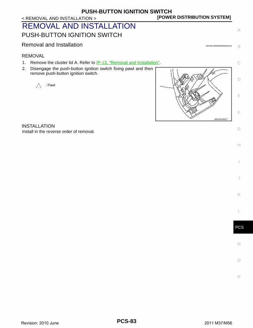
CS
PUSH-BUTTON IGNITION SWITCH[POWER DISTRIBUTION SYSTEM]
C
D
E
F
G
H
I
J
K
L
B
A
O
P
N
P
< REMOVAL AND INSTALLATION >
REMOVAL AND INSTALLATIONPUSH-BUTTON IGNITION SWITCH
Removal and Installation INFOID:0000000006032214
REMOVAL1. Remove the cluster lid A. Refer to IP-13, "Removal and Installation".2. Disengage the push-button ignition switch fixing pawl and then
remove push-button ignition switch.
INSTALLATIONInstall in the reverse order of removal.
: Pawl
JMKIA5306ZZ
PCS-83Revision: 2010 June 2011 M37/M56