electrical machines lec 1+2
DESCRIPTION
These are the slides of electrical machines, made by a teacher at GCU engineering department.TRANSCRIPT

Electrical Machines Lecture 1 (Week 4)
Naveed Iqbal
Naveed Iqbal G.C University Lahore

Objective
Concepts, construction, principles of operation and characteristics of electrical machines.
Single phase and 3-phase circuits, AC/DC Motors, generators, Transformers
Naveed Iqbal G.C University Lahore

Outlines
Magnetic circuits and calculations:
Single-phase and poly-phase circuits.
Transformers
DC machines
AC machines
Naveed Iqbal G.C University Lahore

Readings
A. E. Fitzgerald, Charles Kingsley, Jr. and TStephen D. TUmans,“Electric Machinery,” Sixth Edition, 2003, McGraw-Hill, ISBN:0073660094.
Stephen J. Chapman,T “Electric Machinery FundamentalsT,” Fourth EditionT, 2005, McGraw-Hill, ISBN: 0072465239.
Theodore Wildi, “Electrical Machines, Drives and Power Systems,” Sixth Edition, 2006, Prentice Hall, ISBN: 0131776916
Naveed Iqbal G.C University Lahore

Electrical Machine
Energy can neither be created nor destroy Can be converted from on form to another In electrical machines, one form of energy
is electricity An electrical machine is the generic name
for a device that converts mechanical energy to electrical energy, converts electrical energy to mechanical energy, or changes alternating current from one voltage level to a different voltage level (wikipedia.org)
Naveed Iqbal G.C University Lahore

Electrical Machine
If energy flows from electrical to mechanical domain then machine is motor
If energy flows from mechanical to electrical domain then it will be a generator
Electrical Domain
Mechanical Domain
Magnetic domain
Naveed Iqbal G.C University Lahore

Magnetization
Magnetized bodies: forces act upon at every point throughout their volume
Two poles (N:S) like two charges (+:-)
For +ive charge flux leaves the surface same happens in +ive magnetic pole i.e N
-ive pole or S, magnetic flux enters a surface
Magnetic body has two poles unless magnetic path is close
Naveed Iqbal G.C University Lahore

Magnetization
Naveed Iqbal G.C University Lahore

Laws of Magnetism
First Law: Like pole repel and unlike attract
Force between two poles 𝐹 = 𝑚1𝑚2
𝑟2
m1 and m2 pole strength
Unit pole: when placed at a distance of 1cm from similar pole it repels it with a force of 1 dyne
Magnetic field: space around a magnetic pole. Represented by lines magnetic flux
Naveed Iqbal G.C University Lahore

Magnetic Flux Total lines passing through a given section Represented by Φ Flux from unit pole: At every point on a
sphere of 1cm radius, surrounding a unit pole as center, a similar unit pole is repelled with a force of one dyne.
There must be one line of induction per square centimeter, and since the surface is 4∏ the total flux from the unit pole is 4∏ line
The flux from a pole of strength m is Φ= 4m ∏ lines.
The Flux density is precisely equal to the flux through an area B= ∅/A
Naveed Iqbal G.C University Lahore

Magnetization
Thus a unit north pole is associated with each 4∏ lines leaving a surface and a unit south pole with each 4∏ lines entering a surface.
Magnetic Potential. The magnetic potential of an isolated magnetic pole is the work done in carrying a unit north pole from an infinite distance to the point against the forces in the magnetic field
Naveed Iqbal G.C University Lahore

Magnetization
Magneto motive Force: The difference of magnetic potential two points is called the magneto motive force (m.m.f.) between the points.
Same as e.m.f
Permeability: Permeability is the ratio of the magnetic conductivity of a substance to the magnetic conductivity of air and is represented by μ
Naveed Iqbal G.C University Lahore

Magnetization Magnetic Reluctance: The reluctance of a magnetic
circuit may be defined as the resistance offered by the circuit to the passage of magnetic flux through it and is represented by ℜ it is equal to the ratio of the MMF in a magnetic circuit to the magnetic flux in this circuit.
The definition can be expressed as:
ℜ = ℱ
𝛷
The reluctance of a uniform magnetic circuit can be calculated as
ℜ = 𝑙
𝜇𝑜𝜇𝑟 𝐴
Series Reluctance ℜeq = ℜ1 + ℜ2 + ℜ3 + ….
Parallel Reluctance, 1
ℜ𝑒𝑞=
1
ℜ1+
1
ℜ2+
1
ℜ3+ … … .
Naveed Iqbal G.C University Lahore

Magnetization
Permeance: The permeance of a magnetic path is the reciprocal of its reluctance and is represented by P
P = 1/ ℜ Electromagnetics. The region
surrounding a conductor carrying a current of electricity is a magnetic field.
A current of electricity therefore represents a m.m.f. If the conductor is isolated from other magnetic forces the lines of force will form circles around it.
Naveed Iqbal G.C University Lahore

Magnetization
Maxwell's Corkscrew Rule. The direction of the current and that of the resulting magnetic force are related to one another as the forward travel and the twist of an ordinary corkscrew.
Naveed Iqbal G.C University Lahore

Laws of Induction
Faraday discovered that a current is induced in a closed coil of wire when a magnet is brought near it.
The induced current is due to potential or emf produced in the circuit by changing the number of lines of magnetic flux threading through it or by causing lines of magnetic flux to cut across it.
Naveed Iqbal G.C University Lahore

Laws of Induction
First Law. A change in the number of lines which pass through a closed circuit induces a current around the circuit in such a direction as to oppose the change in the flux threading the circuit.
Second Law. The electromotive force induced around a closed circuit is equal to the rate of change of the flux which passes through the circuit
Naveed Iqbal G.C University Lahore

Ampere’s Law
If Current I flowing through conductor
produces a magnetic field around it of intensity H
If there is magnetic field intensity H around a conductor then current I flows through it
∮H dl=N I dl =differential length of element H =magnetic field intensity = Amps turn
per meter Naveed Iqbal G.C University Lahore

Ampere’s Law
Naveed Iqbal G.C University Lahore

Naveed Iqbal G.C University Lahore

Naveed Iqbal G.C University Lahore

Naveed Iqbal G.C University Lahore

Naveed Iqbal G.C University Lahore

Example A ferromagnetic core is
shown in Figure. The depth of the core is 5 cm. The other dimensions of the core are as shown in the figure. Find the value of the current that will produce a flux of 0.003 Wb. With this current, what is the flux density at the top of the core? What is the flux density at the right side of the core? Assume that the relative permeability of the core is 1000.
Naveed Iqbal G.C University Lahore

Example
Same area
Region 1
Region 2
Regio
n 3
Naveed Iqbal G.C University Lahore

Example
Three regions; top and bottom form one, the left and right forms other two regions If we assume that the mean path length of the flux is in the center of each leg of the core, and if we ignore spreading at the corners of the core, then the path
lengths are l1 = 2(27.5 cm) = 55 cm, l2 = 30 cm, and l3 = 30 cm. The reluctances of these regions are
ℜ1 = 𝑙
μ𝐴=
𝑙
𝜇𝑟𝜇𝑜𝐴=
0.55
1000×4π ×10−7×0.05 ×0.15= 58.36 𝑘𝐴 𝑡/𝑊𝑏
ℜ2 =0.3
1000×4𝜋 ×10−7×0.05 ×0.10= 47.75 𝑘𝐴 t/wb
ℜ3 =0.3
1000×4𝜋 ×10−7×0.05 ×0.05= 95.49 𝑘𝐴 𝑡/𝑊𝑏
ℜT = 58.36 + 47.75 + 95.49 =201.6 kA t/Wb
Naveed Iqbal G.C University Lahore
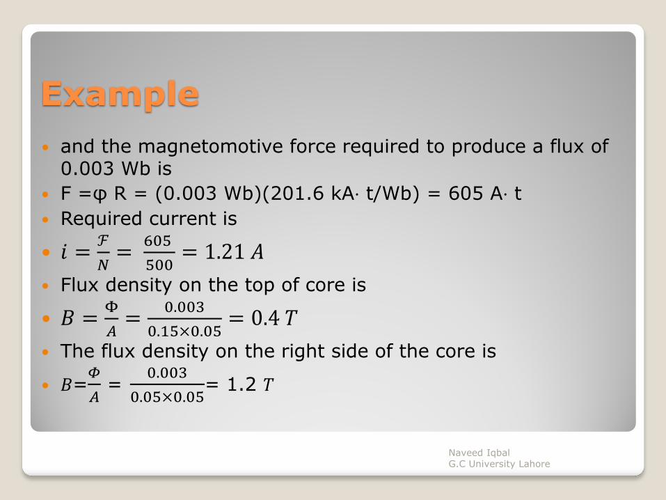
Example
and the magnetomotive force required to produce a flux of 0.003 Wb is
F =φ R = (0.003 Wb)(201.6 kA⋅ t/Wb) = 605 A⋅ t
Required current is
𝑖 =ℱ
𝑁=
605
500= 1.21 𝐴
Flux density on the top of core is
𝐵 =Φ
𝐴=
0.003
0.15×0.05= 0.4 𝑇
The flux density on the right side of the core is
𝐵=𝛷
𝐴 =
0.003
0.05×0.05= 1.2 𝑇
Naveed Iqbal G.C University Lahore
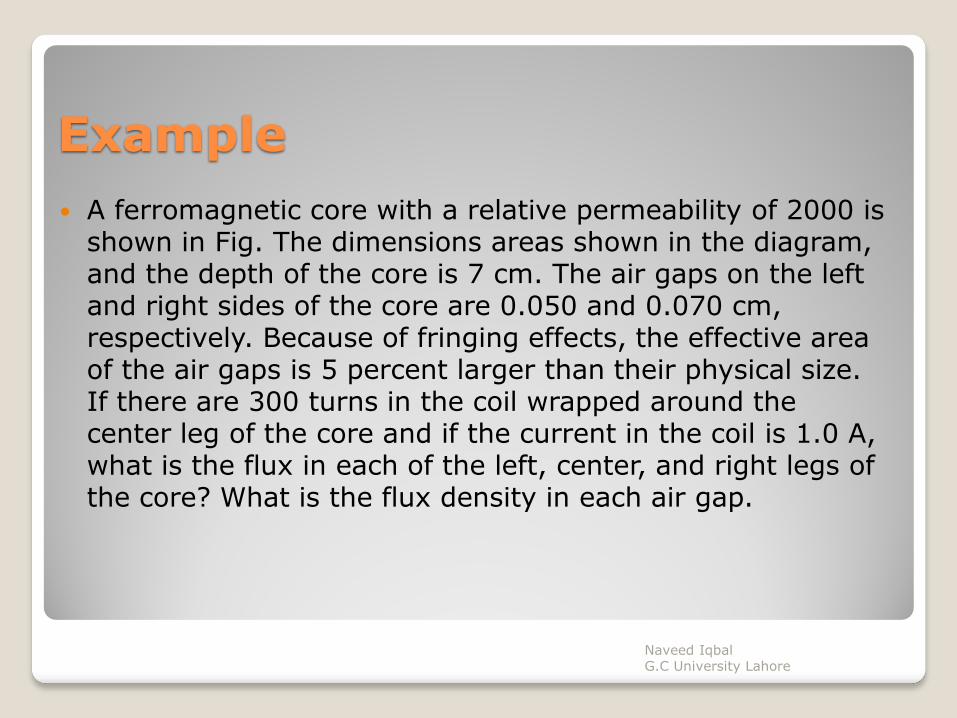
Example
A ferromagnetic core with a relative permeability of 2000 is shown in Fig. The dimensions areas shown in the diagram, and the depth of the core is 7 cm. The air gaps on the left and right sides of the core are 0.050 and 0.070 cm, respectively. Because of fringing effects, the effective area of the air gaps is 5 percent larger than their physical size. If there are 300 turns in the coil wrapped around the center leg of the core and if the current in the coil is 1.0 A, what is the flux in each of the left, center, and right legs of the core? What is the flux density in each air gap.
Naveed Iqbal G.C University Lahore

Naveed Iqbal G.C University Lahore

Example
Let R1 be the reluctance of the left-hand portion of the core.
R2 be the reluctance of the left-hand air gap,
R3 be the reluctance of the right-hand portion of the core,
R4 be the reluctance of the right-hand air gap,
R5 be the reluctance of the center leg of the core
𝑅𝑡 =𝑅1+𝑅2 (𝑅3+𝑅4)
𝑅1+𝑅2+𝑅3+𝑅4
Your home work
Naveed Iqbal G.C University Lahore

Magnetic Hysteresis
When an external magnetic field is applied to a ferro-magnet such as iron, the atomic dipoles align themselves with it.
But when the field is removed, part of the alignment will be retained: the material has become magnetized.
Once magnetized, the magnet will stay magnetized indefinitely. To demagnetize it requires heat or a magnetic field in the opposite direction
It can be described by a plot between B and H
Naveed Iqbal G.C University Lahore

Naveed Iqbal G.C University Lahore

Magnetic Hysteresis
As magnetic field intensity H increases it will increase flux density in a ferromagnetic material until it become saturated
But when we decrease the magnetic flux intensity the curve take a different path shown by red curve
When H is zero, B does not goes to zero and there will be some remnant flux in the material
So, we have to apply negative flux intensity to remove all flux. This is shown by green line
Now, by further applying negative field intensity flux will increase in negative direction until core material saturated
Now again, applying H in positive direction, at H=0, there will be again a remnant flux.
Similarly, again by applying positive H, the B increases until material of core become saturated.
Naveed Iqbal G.C University Lahore

Eddy Currents
A time-changing flux induces voltage within a ferromagnetic core.
These voltages cause swirls of current to flow within the core – eddy currents
Energy is dissipated (in the form of heat) because these eddy currents are flowing in a resistive material (iron)
4. The amount of energy lost to eddy currents is proportional to the size of the paths they follow within the core
Naveed Iqbal G.C University Lahore

Eddy Currents
ferromagnetic core should be broken up into small strips with lamination between them
Naveed Iqbal G.C University Lahore