essentials of rotating electrical...
TRANSCRIPT
Essentials of Rotating Electrical Machines
All electrical machines are variations on a common set of fundamental principles, which apply alike to dc and ac types, to generators and motors, to steady-state and transient conditions.
Machine Construction
Rotating machines
1. Common Features:
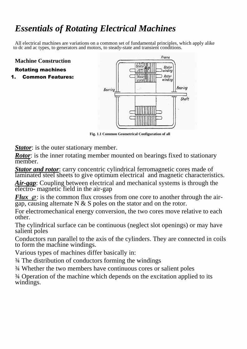
Fig. 1.1 Common Geometrical Configuration of all
Stator: is the outer stationary member.
Rotor: is the inner rotating member mounted on bearings fixed to stationary member.
Stator and rotor: carry concentric cylindrical ferromagnetic cores made of laminated steel sheets to give optimum electrical and magnetic characteristics.
Air-gap: Coupling between electrical and mechanical systems is through the electro- magnetic field in the air-gap
Flux φ: is the common flux crosses from one core to another through the air-gap, causing alternate N & S poles on the stator and on the rotor.
For electromechanical energy conversion, the two cores move relative to each other.
The cylindrical surface can be continuous (neglect slot openings) or may have salient poles
Conductors run parallel to the axis of the cylinders. They are connected in coils to form the machine windings.
Various types of machines differ basically in:
¾ The distribution of conductors forming the windings
¾ Whether the two members have continuous cores or salient poles
¾ Operation of the machine which depends on the excitation applied to its windings.
1.
Types of winding:
The windings of electrical machines are of two main types:
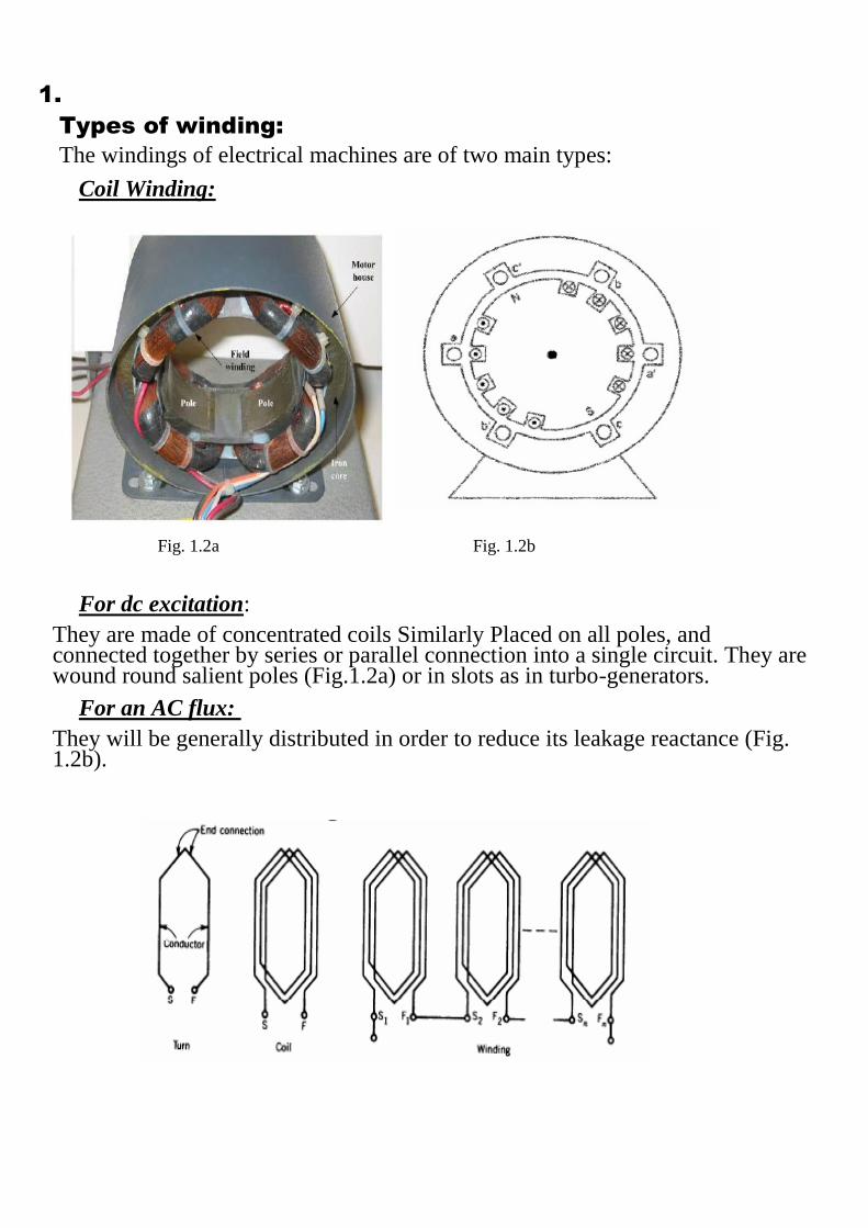
Coil Winding:
Fig. 1.2a Fig. 1.2b
For dc excitation:
They are made of concentrated coils Similarly Placed on all poles, and connected together by series or parallel connection into a single circuit. They are wound round salient poles (Fig.1.2a) or in slots as in turbo-generators.
For an AC flux:
They will be generally distributed in order to reduce its leakage reactance (Fig. 1.2b).
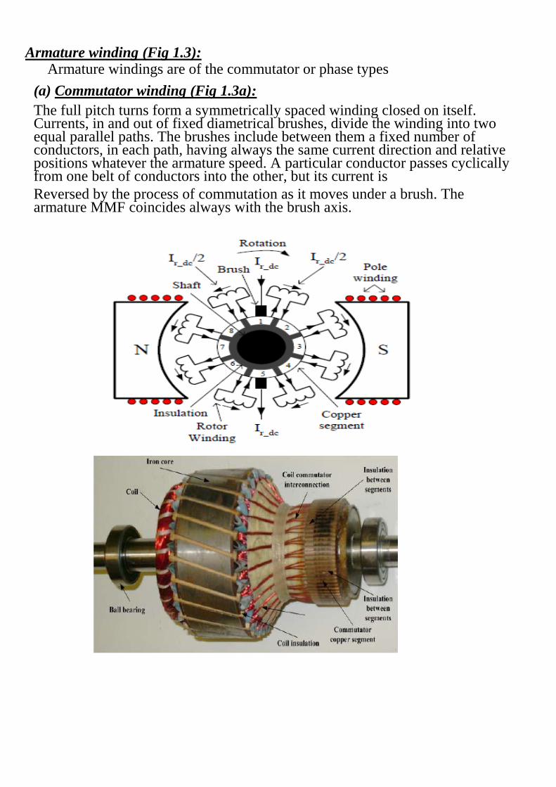
Armature winding (Fig 1.3): Armature windings are of the commutator or phase types
(a) Commutator winding (Fig 1.3a):
The full pitch turns form a symmetrically spaced winding closed on itself. Currents, in and out of fixed diametrical brushes, divide the winding into two equal parallel paths. The brushes include between them a fixed number of conductors, in each path, having always the same current direction and relative positions whatever the armature speed. A particular conductor passes cyclically from one belt of conductors into the other, but its current is
Reversed by the process of commutation as it moves under a brush. The armature MMF coincides always with the brush axis.
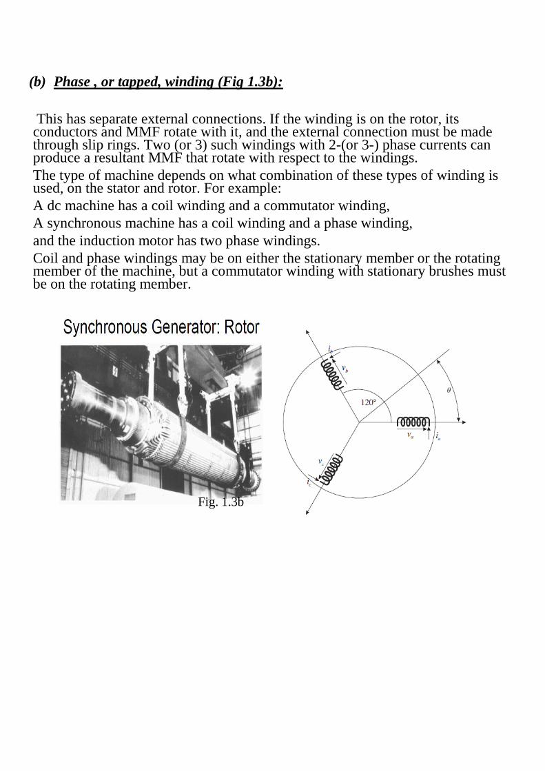
(b) Phase , or tapped, winding (Fig 1.3b):
This has separate external connections. If the winding is on the rotor, its conductors and MMF rotate with it, and the external connection must be made through slip rings. Two (or 3) such windings with 2-(or 3-) phase currents can produce a resultant MMF that rotate with respect to the windings.
The type of machine depends on what combination of these types of winding is used, on the stator and rotor. For example:
A dc machine has a coil winding and a commutator winding,
A synchronous machine has a coil winding and a phase winding,
and the induction motor has two phase windings.
Coil and phase windings may be on either the stationary member or the rotating member of the machine, but a commutator winding with stationary brushes must be on the rotating member.
Fig. 1.3b
2. The Basic 2-pole Machine
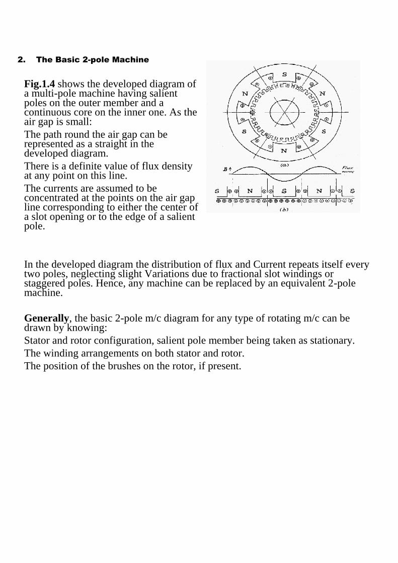
Fig.1.4 shows the developed diagram of a multi-pole machine having salient poles on the outer member and a continuous core on the inner one. As the air gap is small:
The path round the air gap can be represented as a straight in the developed diagram.
There is a definite value of flux density at any point on this line.
The currents are assumed to be concentrated at the points on the air gap line corresponding to either the center of a slot opening or to the edge of a salient pole.
In the developed diagram the distribution of flux and Current repeats itself every two poles, neglecting slight Variations due to fractional slot windings or staggered poles. Hence, any machine can be replaced by an equivalent 2-pole machine.
Generally, the basic 2-pole m/c diagram for any type of rotating m/c can be drawn by knowing:
Stator and rotor configuration, salient pole member being taken as stationary.
The winding arrangements on both stator and rotor.
The position of the brushes on the rotor, if present.
Conventions
i. Any machine can be replaced by 2-pole machine (flux and current distribution under one pair of poles repeats itself under all other pairs). Number of poles must be used when determining torque (increased), and speed (reduced)
ii. Each winding forming a single circuit is represented by a single coil.
iii. Field is wound around the d-axis. q-axis is perpendicular to d-axis (90o lagging, vertical).
iv. Positive direction of current in any coil is towards the coil, entering from the lead nearer to the center. Positive direction of flux linking a coil is radially outwards.
v. Lower case v for voltage impressed, and I for current measured in the same direction as v. This means that P = VI flows into the circuit. Reversing V or I means generation action.
vi. Positive direction of rotation is clockwise (cw).
vii. Same for positive torque.
viii. Capital L and X are for self inductances (total) and reactance. Small l and x are for leakage inductance or reactance.
ix. Capital letters to indicate coils. Small letters for subscripts for voltages and currents.
(a) Commutator Machines
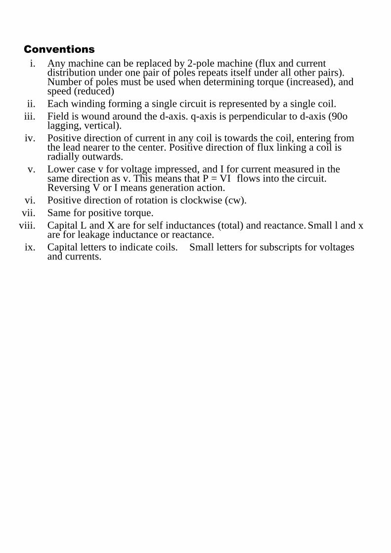
Fig. 1.4 (a) separately excited dc motor Fig. 1.4(b) the basic 2-pole machine representation
As the armature rotates, the direction and magnitude of Fqr (arm MMF) remains unchanged. Hence, commutator winding as a concentrated stationary coils “QR”.
The Field produced by N and S poles and that produced by coil “DS” are identical.
The stationary coil “QR” generates the same rotational voltage as that generated by that of the commutator winding when acting as a generator.
When acting as a motor the same torque is developed for the same current in coil “QR” and in the commutator winding.
“QR” is a “pseudo-stationary coil” or “quasi- stationary coil”:
i. A current in a coil produces a field which is stationary in space.
ii. A rotational voltage can however be induced in the coil by virtue of its being on the moving element, though the coil does not move.
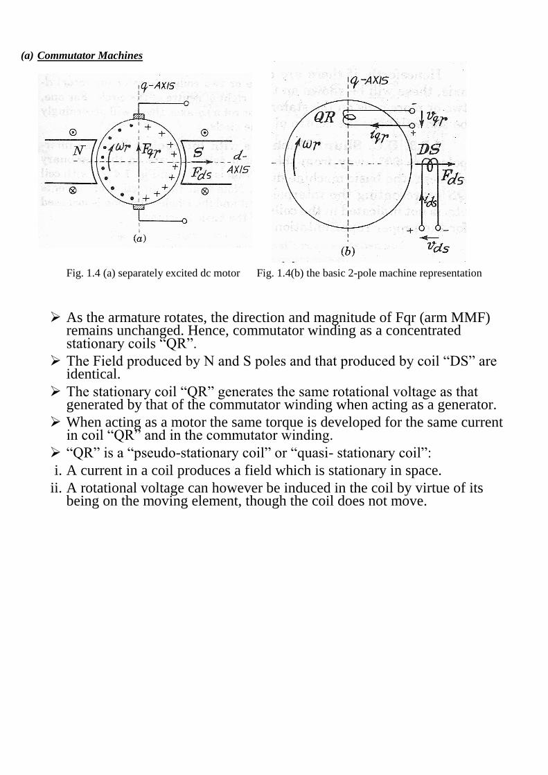
(b) DC Compound Machine
i. The dc compound machine, in addition to the shunt field winding, carries a series winding on the main poles (coil DSE).
ii. No mention is made for differential or integral compounding. Coils representing various windings are shown with no interconnection among them.
(c) DC Shunt Machine With interpoles
Interpoles are 90o away from the main poles and are on the stationary element. They are represented by the coil “QS”.
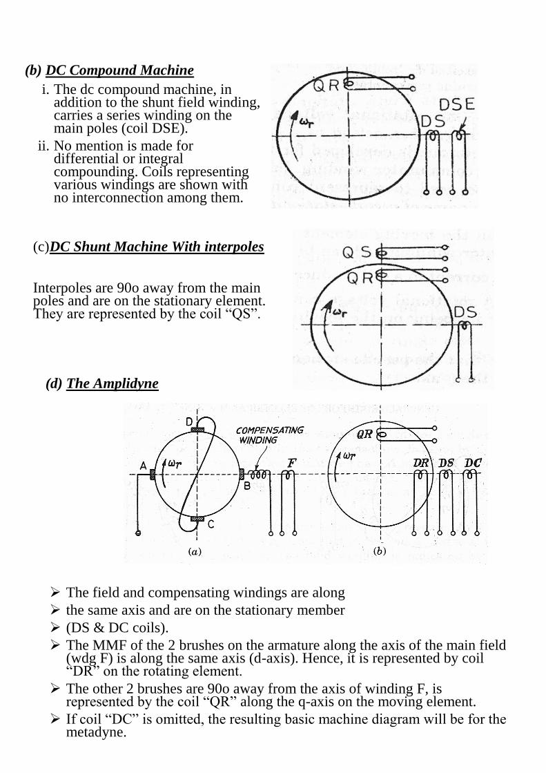
(d) The Amplidyne
The field and compensating windings are along
the same axis and are on the stationary member
(DS & DC coils).
The MMF of the 2 brushes on the armature along the axis of the main field (wdg F) is along the same axis (d-axis). Hence, it is represented by coil “DR” on the rotating element.
The other 2 brushes are 90o away from the axis of winding F, is represented by the coil “QR” along the q-axis on the moving element.
If coil “DC” is omitted, the resulting basic machine diagram will be for the metadyne.

(e) Single Phase AC Series Machine
Stator has 1-phase winding which is excited by ac voltage. It is represented by coil “DS”.
Rotor has a winding whose magnetic axis is 90o
Away from stator wdg, represented by coil ”QR”.
Same basic machine diagram also represents dc series machine.
(f) Repulsion Motor
1-ph stator winding is represented by coil “DS”.
Rotor consists of a commutator winding with a pair of short circuited brushes displaced from stator field-axis (d-axis) by an angle α “coil AR”. Field due to rotor currents has a component 90o to d-axis. The interaction between this component and the field due to coil “DS” results in production of torque.
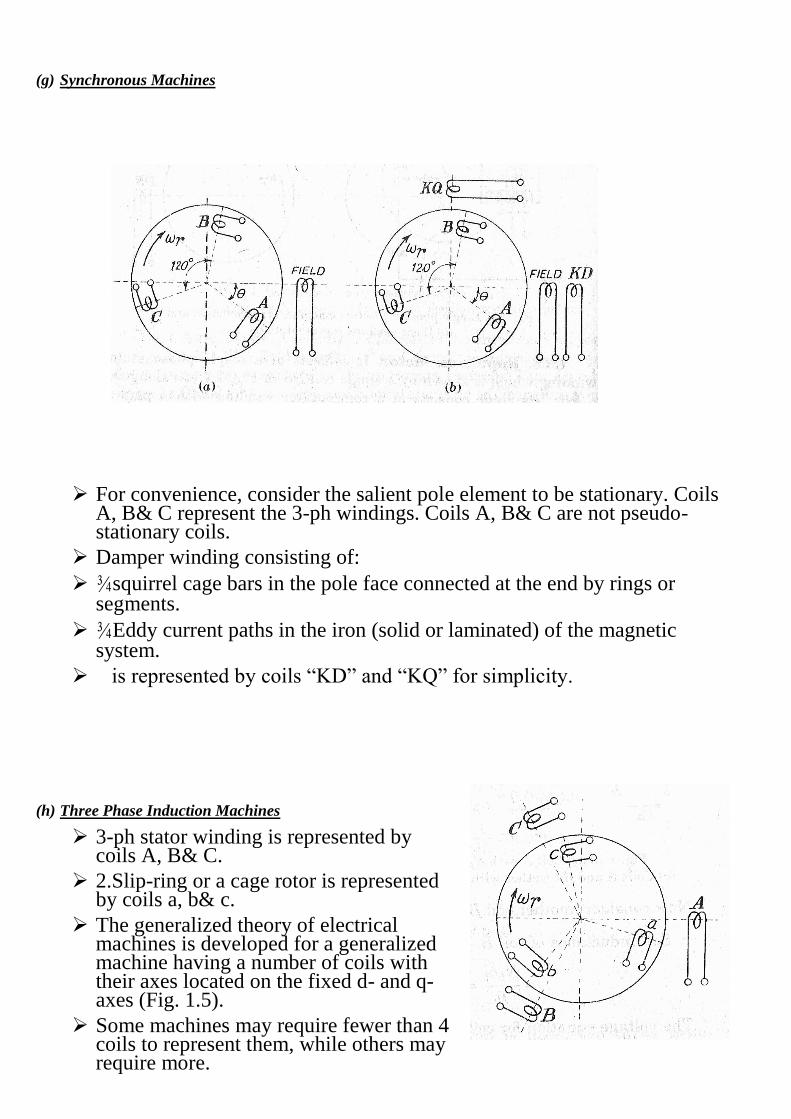
(g) Synchronous Machines
For convenience, consider the salient pole element to be stationary. Coils A, B& C represent the 3-ph windings. Coils A, B& C are not pseudo-stationary coils.
Damper winding consisting of:
¾squirrel cage bars in the pole face connected at the end by rings or segments.
¾Eddy current paths in the iron (solid or laminated) of the magnetic system.
is represented by coils “KD” and “KQ” for simplicity.
(h) Three Phase Induction Machines
3-ph stator winding is represented by coils A, B& C.
2.Slip-ring or a cage rotor is represented by coils a, b& c.
The generalized theory of electrical machines is developed for a generalized machine having a number of coils with their axes located on the fixed d- and q- axes (Fig. 1.5).
Some machines may require fewer than 4 coils to represent them, while others may require more.
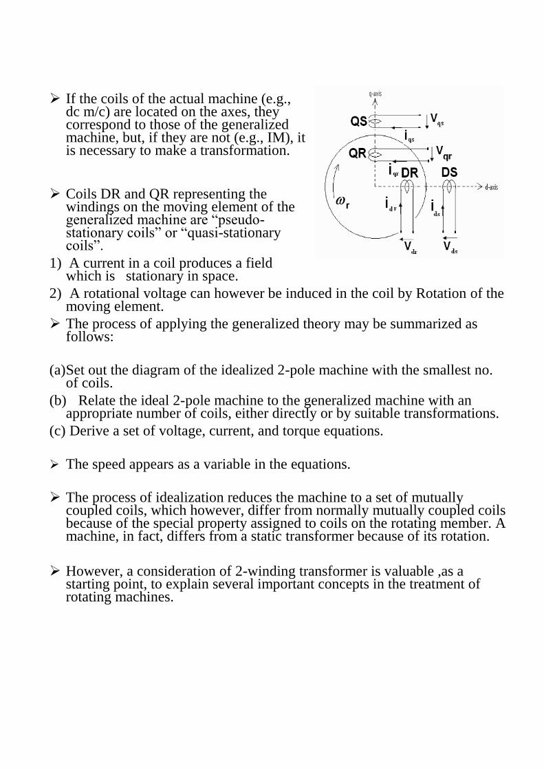
If the coils of the actual machine (e.g., dc m/c) are located on the axes, they correspond to those of the generalized machine, but, if they are not (e.g., IM), it is necessary to make a transformation.
Coils DR and QR representing the windings on the moving element of the generalized machine are “pseudo-stationary coils” or “quasi-stationary coils”.
1) A current in a coil produces a field which is stationary in space.
2) A rotational voltage can however be induced in the coil by Rotation of the moving element.
The process of applying the generalized theory may be summarized as follows:
(a) Set out the diagram of the idealized 2-pole machine with the smallest no. of coils.
(b) Relate the ideal 2-pole machine to the generalized machine with an appropriate number of coils, either directly or by suitable transformations.
(c) Derive a set of voltage, current, and torque equations.
The speed appears as a variable in the equations.
The process of idealization reduces the machine to a set of mutually coupled coils, which however, differ from normally mutually coupled coils because of the special property assigned to coils on the rotating member. A machine, in fact, differs from a static transformer because of its rotation.
However, a consideration of 2-winding transformer is valuable ,as a starting point, to explain several important concepts in the treatment of rotating machines.
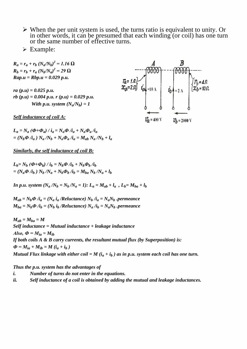
When the per unit system is used, the turns ratio is equivalent to unity. Or in other words, it can be presumed that each winding (or coil) has one turn or the same number of effective turns.
Example:
Ra = ra + rb (Na/Nb)2 = 1.16 Ω
Rb = rb + ra (Nb/Na)2 = 29 Ω
Rap.u = Rbp.u = 0.029 p.u.
ra (p.u) = 0.025 p.u.
rb (p.u) = 0.004 p.u. r (p.u) = 0.029 p.u.
With p.u. system (Na/Nb) = 1
Self inductance of coil A:
La = Na (Ф+Фa) / ia = NaФ /ia + NaФa /ia
= (NbФ /ia ) Na /Nb + NaФa /ia = Mab Na /Nb + la
Similarly, the self inductance of coil B:
Lb= Nb (Ф+Фb) / ib = NbФ /ib + NbФb /ib
= (NaФ /ib ) Nb /Na + NbФb /ib = Mba Nb /Na + lb
In p.u. system (Na /Nb = Nb /Na = 1): La = Mab + la , Lb= Mba + lb
Mab = NbФ /ia = (Na ia /Reluctance) Nb /ia = NaNb .permeance
Mba = NbФ /ib = (Nb ib /Reluctance) Na /ib = NaNb .permeance
Mab = Mba = M
Self inductance = Mutual inductance + leakage inductance
Also, Ф = Mia = Mib
If both coils A & B carry currents, the resultant mutual flux (by Superposition) is:
Ф = Mia + Mib = M (ia + ib )
Mutual Flux linkage with either coil = M (ia + ib ) as in p.u. system each coil has one turn.
Thus the p.u. system has the advantages of
i. Number of turns do not enter in the equations.
ii. Self inductance of a coil is obtained by adding the mutual and leakage inductances.
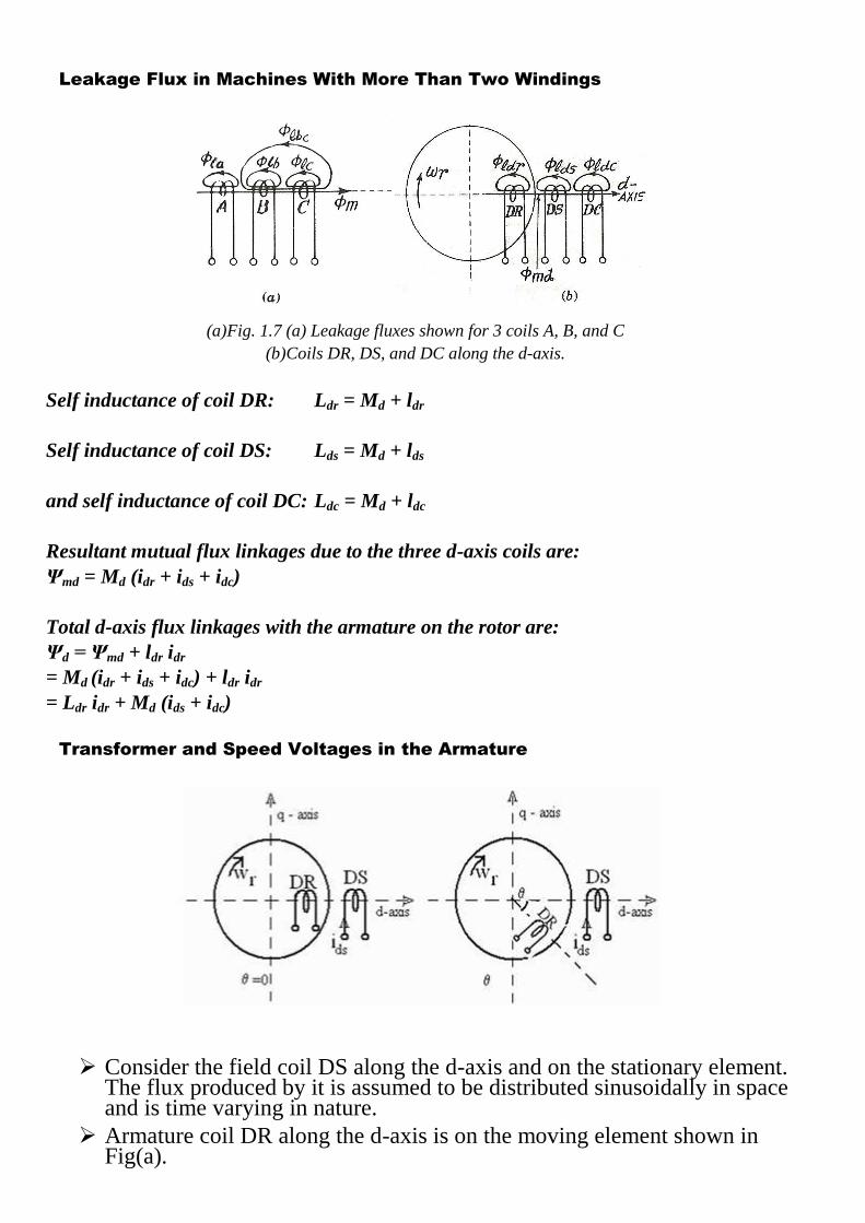
Leakage Flux in Machines With More Than Two Windings
(a)Fig. 1.7 (a) Leakage fluxes shown for 3 coils A, B, and C
(b)Coils DR, DS, and DC along the d-axis.
Self inductance of coil DR: Ldr = Md + ldr
Self inductance of coil DS: Lds = Md + lds
and self inductance of coil DC: Ldc = Md + ldc
Resultant mutual flux linkages due to the three d-axis coils are:
Ψmd = Md (idr + ids + idc)
Total d-axis flux linkages with the armature on the rotor are:
Ψd = Ψmd + ldr idr
= Md (idr + ids + idc) + ldr idr
= Ldr idr + Md (ids + idc)
Transformer and Speed Voltages in the Armature
Consider the field coil DS along the d-axis and on the stationary element. The flux produced by it is assumed to be distributed sinusoidally in space and is time varying in nature.
Armature coil DR along the d-axis is on the moving element shown in Fig(a).
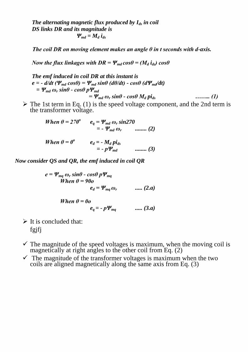
The alternating magnetic flux produced by Ids in coil
DS links DR and its magnitude is
Ψmd = Md ids
The coil DR on moving element makes an angle θ in t seconds with d-axis.
Now the flux linkages with DR = Ψmd cosθ = (Md ids) cosθ
The emf induced in coil DR at this instant is
e = - d/dt (Ψmd cosθ) = Ψmd sinθ (dθ/dt) - cosθ (dΨmd/dt)
= Ψmd ωr sinθ - cosθ pΨmd
= Ψmd ωr sinθ - cosθ Md pids …….. (1)
The 1st term in Eq. (1) is the speed voltage component, and the 2nd term is the transformer voltage.
When θ = 270o eq = Ψmd ωr sin270
= - Ψmd ωr ........ (2)
When θ = 0o ed = - Md pids
= - pΨmd ........ (3)
Now consider QS and QR, the emf induced in coil QR
e = Ψmq ωr sinθ - cosθ pΨmq
When θ = 90o
ed = Ψmq ωr ..... (2.a)
When θ = 0o
eq = - pΨmq ..... (3.a)
It is concluded that:
fgjfj
The magnitude of the speed voltages is maximum, when the moving coil is magnetically at right angles to the other coil from Eq. (2)
The magnitude of the transformer voltages is maximum when the two coils are aligned magnetically along the same axis from Eq. (3)
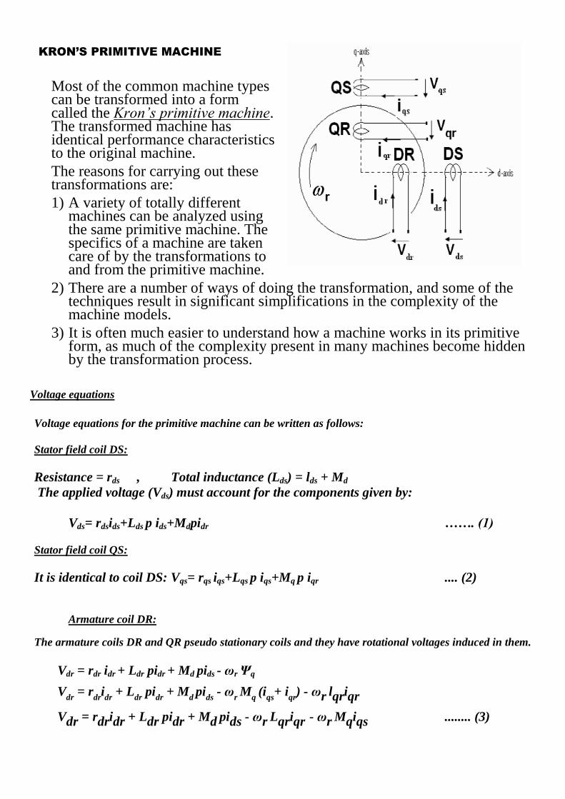
KRON’S PRIMITIVE MACHINE
Most of the common machine types can be transformed into a form called the Kron’s primitive machine. The transformed machine has identical performance characteristics to the original machine.
The reasons for carrying out these transformations are:
1) A variety of totally different machines can be analyzed using the same primitive machine. The specifics of a machine are taken care of by the transformations to and from the primitive machine.
2) There are a number of ways of doing the transformation, and some of the techniques result in significant simplifications in the complexity of the machine models.
3) It is often much easier to understand how a machine works in its primitive form, as much of the complexity present in many machines become hidden by the transformation process.
Voltage equations
Voltage equations for the primitive machine can be written as follows:
Stator field coil DS:
Resistance = rds , Total inductance (Lds) = lds + Md
The applied voltage (Vds) must account for the components given by:
Vds= rdsids+Lds p ids+Mdpidr ……. (1)
Stator field coil QS:
It is identical to coil DS: Vqs= rqs iqs+Lqs p iqs+Mq p iqr .... (2)
Armature coil DR: The armature coils DR and QR pseudo stationary coils and they have rotational voltages induced in them.
Vdr = rdr idr + Ldr pidr + Md pids - ωr Ψq
Vdr = r
dridr + L
dr pidr + M
d pi
ds - ωr Mq (iqs+ i
qr) - ωr lqriqr
Vdr = rdridr + Ldr pidr + Md pids - ωr Lqriqr - ωr Mqiqs ........ (3)
Armature coil QR:
This coil is similar to coil DR. Using the above procedure, the applied voltage Vqr is equal to:
Vqr = rqriqr + Lqr piqr + Mq piqs + ωr Ldridr+ ωr Mdids ……......... (4)
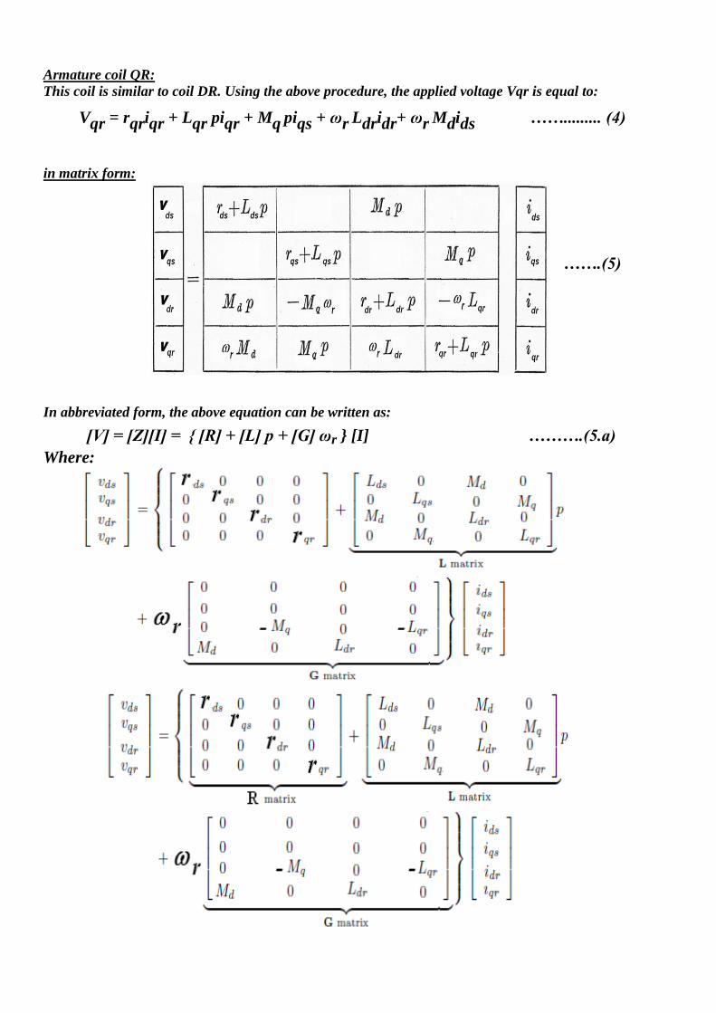
in matrix form:
…….(5)
In abbreviated form, the above equation can be written as:
[V] = [Z][I] = [R] + [L] p + [G] ωr [I] ……….(5.a)
Where:
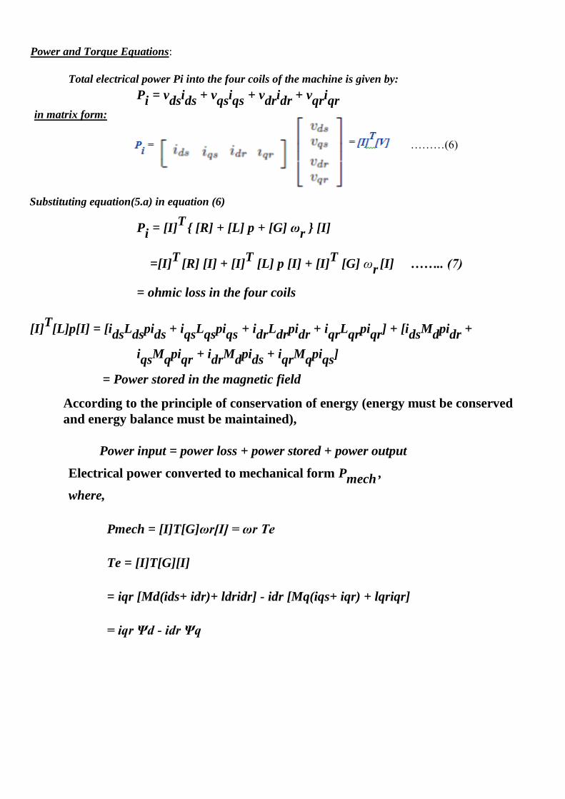
Power and Torque Equations:
Total electrical power Pi into the four coils of the machine is given by:
Pi = vdsids + vqsiqs + vdridr + vqriqr in matrix form:
………(6)
Substituting equation(5.a) in equation (6)
Pi = [I]T
[R] + [L] p + [G] ωr [I]
=[I]T
[R] [I] + [I]T
[L] p [I] + [I]T
[G] ωr [I] …….. (7)
= ohmic loss in the four coils
[I]T
[L]p[I] = [idsLdspids + iqsLqspiqs + idrLdrpidr + iqrLqrpiqr] + [idsMdpidr +
iqsMqpiqr + idrMdpids + iqrMqpiqs]
= Power stored in the magnetic field
According to the principle of conservation of energy (energy must be conserved
and energy balance must be maintained),
Power input = power loss + power stored + power output
Electrical power converted to mechanical form Pmech ,
where,
Pmech = [I]T[G]ωr[I] = ωr Te
Te = [I]T[G][I]
= iqr [Md(ids+ idr)+ ldridr] - idr [Mq(iqs+ iqr) + lqriqr]
= iqr Ψd - idr Ψq
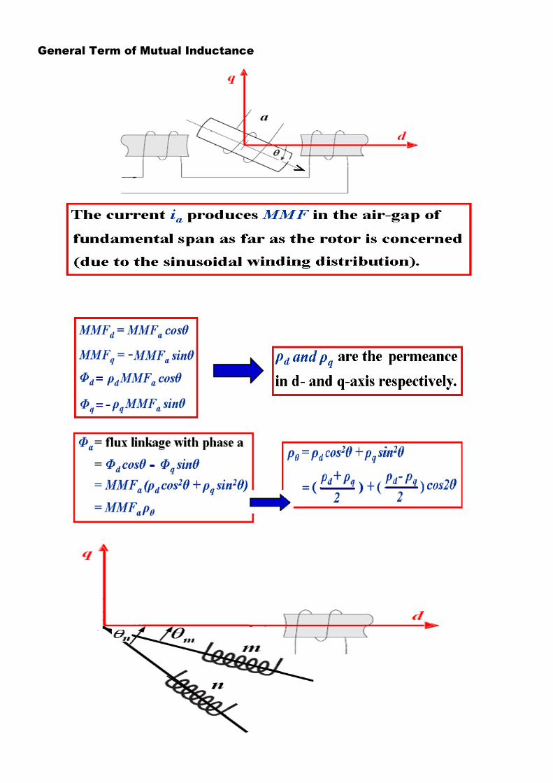
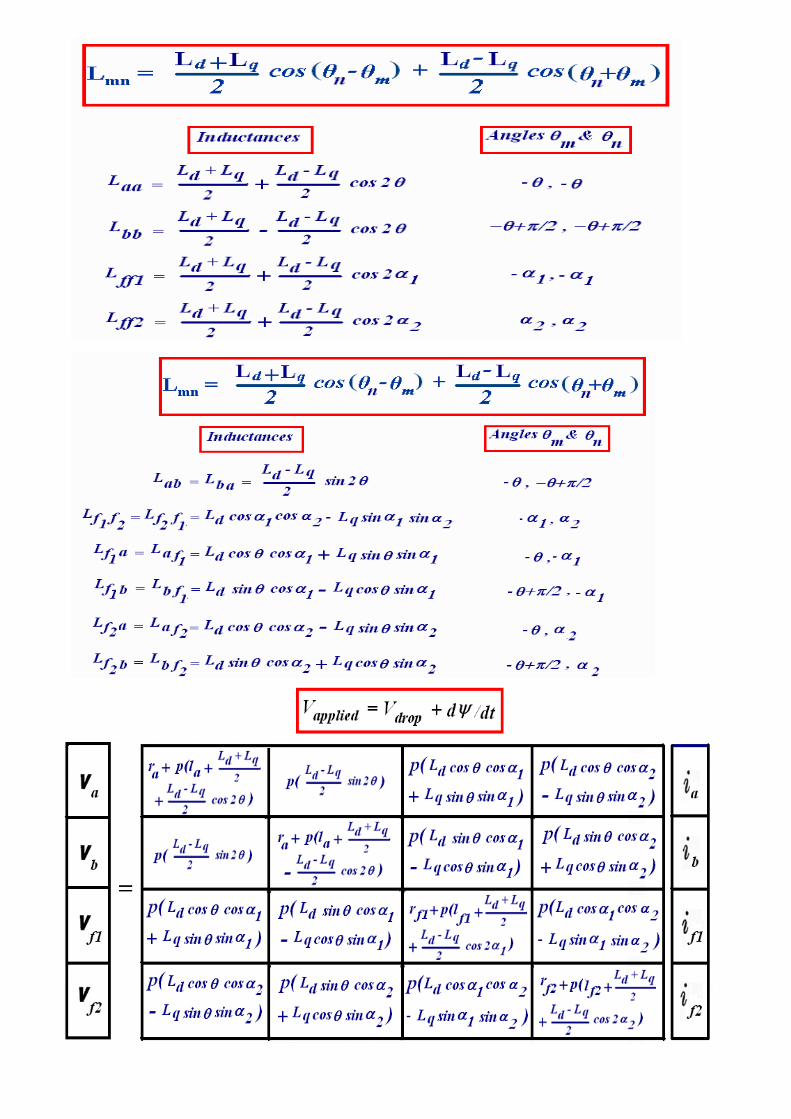
General Term of Mutual Inductance
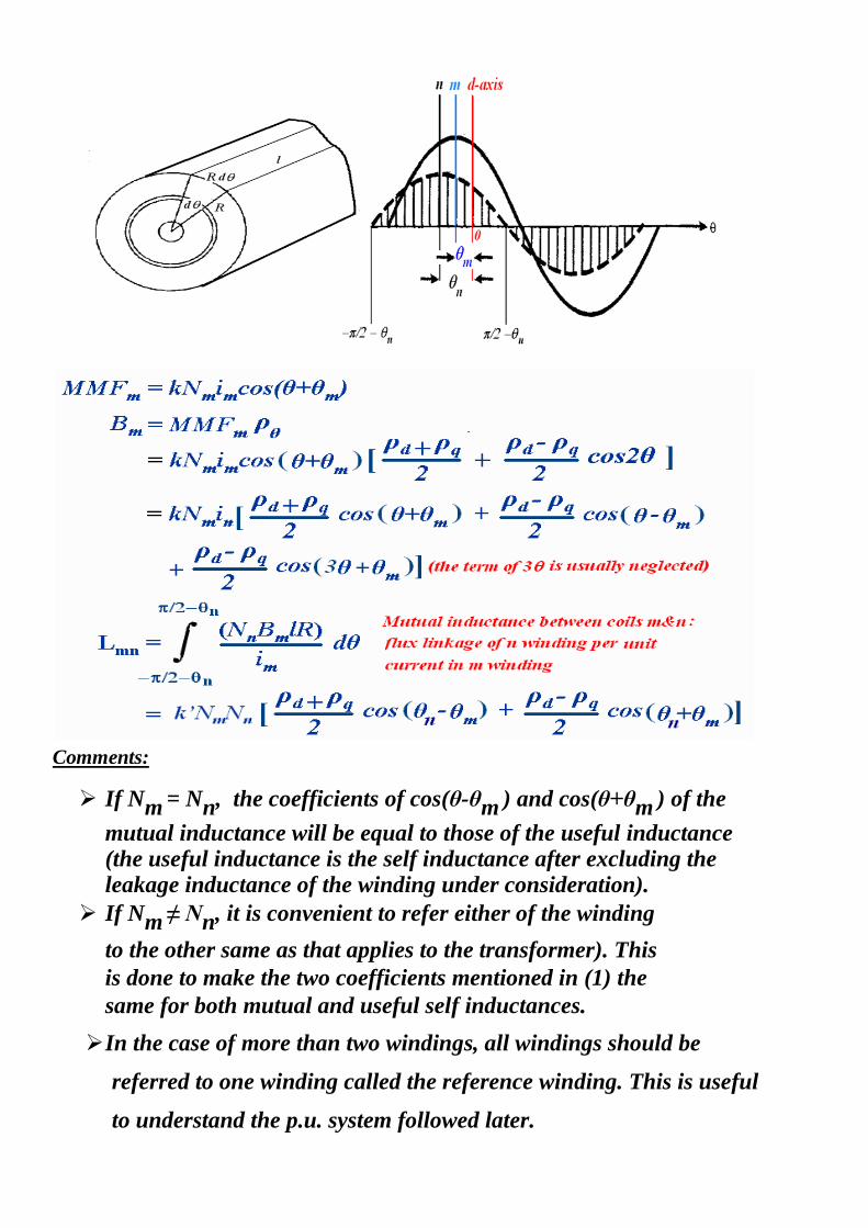
Comments:
If Nm = Nn, the coefficients of cos(θ-θm ) and cos(θ+θm ) of the
mutual inductance will be equal to those of the useful inductance (the useful inductance is the self inductance after excluding the leakage inductance of the winding under consideration).
If Nm ≠ Nn, it is convenient to refer either of the winding
to the other same as that applies to the transformer). This
is done to make the two coefficients mentioned in (1) the
same for both mutual and useful self inductances.
In the case of more than two windings, all windings should be
referred to one winding called the reference winding. This is useful
to understand the p.u. system followed later.
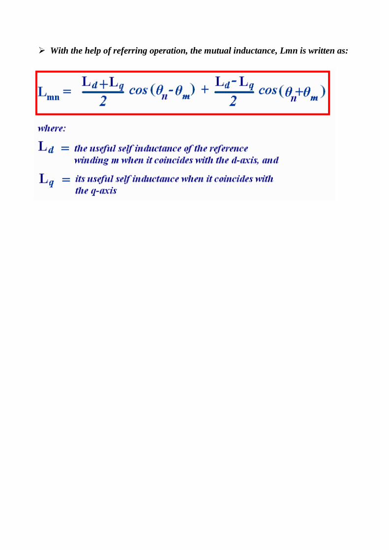
With the help of referring operation, the mutual inductance, Lmn is written as:
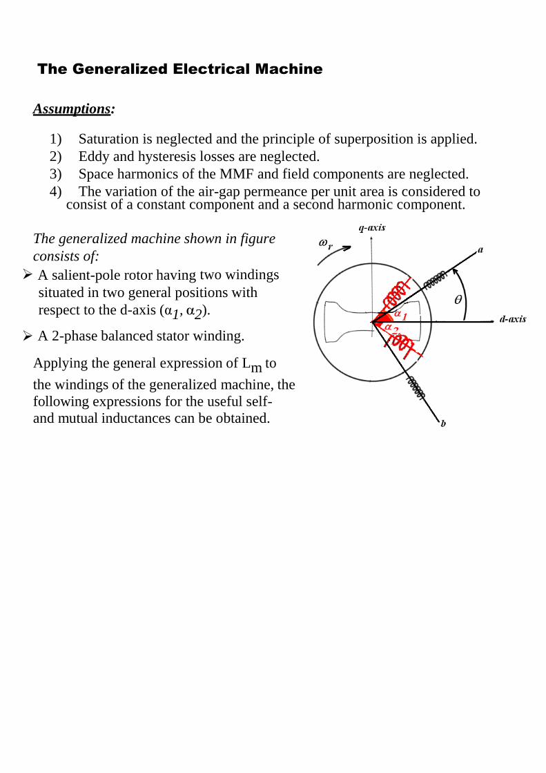
The Generalized Electrical Machine
Assumptions:
1) Saturation is neglected and the principle of superposition is applied.
2) Eddy and hysteresis losses are neglected.
3) Space harmonics of the MMF and field components are neglected.
4) The variation of the air-gap permeance per unit area is considered to consist of a constant component and a second harmonic component.
The generalized machine shown in figure
consists of:
A salient-pole rotor having two windings
situated in two general positions with
respect to the d-axis (α1, α2).
A 2-phase balanced stator winding.
Applying the general expression of Lm to
the windings of the generalized machine, the
following expressions for the useful self-
and mutual inductances can be obtained.
The presence of θ and p = d/dt make the machine equations nonlinear
differential equations since as the machine rotates θ varies with time.
a. The current and inductance terms vary with time.
b. To determine the machine currents, we need the inverse of the impedance
matrix, which is not applicable as it includes functions of time.
c. Note that the operator p operates upon the product of functions of θ and the
current (both are functions of time). Straightforward determination of [Z]-1
would separate these two functions which are not rightful.
d. The use of commutator transformation C2 will eliminate functions of θ from
the impedance matrix. This will linearize the equations
