electrical design guide - winnipeg.ca · wstp structural design guideline winnipeg ... wstp...
TRANSCRIPT
Revision: PB Page 1 of 19WSTP Structural Design Guideline
Winnipeg Document Code:
1
Wrnmpeg
The City of Winnipeg
Winnipeg Sewage Treatment Program
Structural Design Guideline
Document Code:
Revision: PB
Approved By:
Duane Griffin, Bra34’f’Head-
Wastewater Planning & Project Delivery
N:\WSTP Design Standards\Working\Design Guidelines\WSTP Structural Design Guideline RPB.docx

WSTP Structural Design Guideline
Revision: PB Page 3 of 19
Document Code:
N:\WSTP Design Standards\Working\Design Guidelines\WSTP Structural Design Guideline RPB.docx
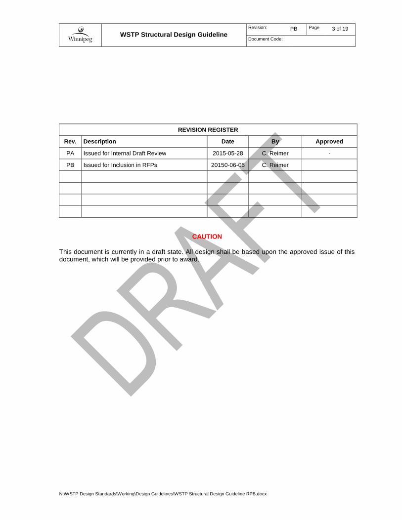
REVISION REGISTER
Rev. Description Date By Approved
PA Issued for Internal Draft Review 2015-05-28 C. Reimer -
PB Issued for Inclusion in RFPs 20150-06-05 C. Reimer
CAUTION
This document is currently in a draft state. All design shall be based upon the approved issue of this document, which will be provided prior to award.

WSTP Structural Design Guideline
Revision: PB Page 4 of 19
Document Code:
N:\WSTP Design Standards\Working\Design Guidelines\WSTP Structural Design Guideline RPB.docx
This page is intentionally blank.

WSTP Structural Design Guideline
Revision: PB Page 5 of 19
Document Code:
N:\WSTP Design Standards\Working\Design Guidelines\WSTP Structural Design Guideline RPB.docx
Table of Contents
1 Introduction ................................................................................................... 7
1.1 Scope of the Standard .................................................................................................. 7 1.2 Application .................................................................................................................... 7 1.3 Deviations from Standard ............................................................................................. 7 1.4 Acronyms and Abbreviations ........................................................................................ 8
2 General ........................................................................................................... 9
2.1 Design Codes and Standards ...................................................................................... 9 2.2 References ................................................................................................................... 9 2.3 Other City Standards .................................................................................................... 9 2.4 Units .............................................................................................................................. 9
3 Design Loads ............................................................................................... 11
3.1 General ....................................................................................................................... 11 3.2 Dead Loads ................................................................................................................ 11 3.3 Collateral Loads .......................................................................................................... 11 3.4 Live Loads .................................................................................................................. 12 3.5 Seismic Loads ............................................................................................................ 12 3.6 Wind Loads ................................................................................................................. 13 3.7 Snow Loads ................................................................................................................ 13 3.8 Rain Loads ................................................................................................................. 13 3.9 Ice Loads .................................................................................................................... 13 3.10 Impact Loads .............................................................................................................. 14 3.11 Thermal Loads ............................................................................................................ 14 3.12 Liquid Loads ............................................................................................................... 15 3.13 Earth Loads ................................................................................................................ 15 3.14 Test Loads .................................................................................................................. 15 3.15 Blast Loads ................................................................................................................. 15 3.16 Insurance Load Requirements ................................................................................... 15 3.17 Load Combinations ..................................................................................................... 15 3.18 Deflection Criteria ....................................................................................................... 16 3.19 Vibration Design Criteria ............................................................................................. 16 3.20 Structural System Requirements ................................................................................ 17
4 Maintenance and Safety ............................................................................. 18
4.1 Maintenance ............................................................................................................... 18 4.2 Safety .......................................................................................................................... 18
5 Structural Design Team Responsibilities .................................................. 19
5.1 General ....................................................................................................................... 19 5.2 Drawings ..................................................................................................................... 20
5.2.1 General Requirements .................................................................................. 20 5.2.2 Legend ........................................................................................................... 20 5.2.3 General Notes Drawing ................................................................................. 20 5.2.4 Foundation / Piling Drawings ......................................................................... 20 5.2.5 Pile Schedule and Details ............................................................................. 20 5.2.6 Structural Plan Drawings ............................................................................... 21 5.2.7 Structural Section and Detail Drawings ......................................................... 21

WSTP Structural Design Guideline
Revision: PB Page 6 of 19
Document Code:
N:\WSTP Design Standards\Working\Design Guidelines\WSTP Structural Design Guideline RPB.docx
5.2.8 Concrete Reinforcing Drawings ..................................................................... 21 5.2.9 Detail Drawings ............................................................................................. 21 5.2.10 3D Model ....................................................................................................... 21
5.3 Structural Design Calculations ................................................................................... 22
WSTP Structural Design Guideline
Revision: PA Page 7 of 19
Document Code:
N:\WSTP Design Standards\Working\Design Guidelines\WSTP Structural Design Guideline RPB.docx
1 INTRODUCTION
This document identifies the standard design requirements that are applicable to any structural work within the City of Winnipeg wastewater treatment facilities.
1.1 Scope of the Standard
These design requirements will apply to the following facilities:
Wastewater treatment plants
1.2 Application
The scope and intent of this document is to convey general design guidance and expectations regarding structural design. This document does address specifics related to design type, selection, and configuration; however the indicated requirements are presented without knowledge of the specific building implementation. It is not within the scope of this document to provide detailed design direction, and it will be the responsibility of the respective structural designers to fully develop the structural details with general conformance to the concepts presented herein. This standard shall not be construed as comprehensive structural engineering design requirements or negate the requirement for professional structural engineer’s involvement. Any design must be executed under the responsibility and seal of the respective engineer in each instance, and must be performed in conformance with all applicable codes and standards, as well as good engineering practice.
Existing facilities do not necessarily comply with this standard. The expectations regarding application of this standard to maintenance and minor upgrades at existing facilities must be assessed on a case-by-case basis; however general guidelines for application are presented as follows:
All new buildings are expected to comply with this standard.
All major upgrades to a building are expected to comply with this standard; however in some cases compromise with the configuration of the existing facility design may be required.
All minor upgrades should utilize this standard as far as practical for new work; however in some cases compromise with the configuration of the existing facility design may be required.
1.3 Deviations from Standard
It is expected that there will be occasional situations where the design architect / engineer will propose a deviation from this design guideline. The rational for potential deviations from the design guideline may include:
Evolution of technology,
Updates to standards and regulations,
Practical limitations due to existing conditions on site, or
Significant cost benefits to the City due to specific project constraints.
For each proposed deviation from this standard, fully complete a WSTP Standards Deviation Form and submit to the City project manager for approval. Do not proceed with the proposed deviation unless approval is received from the City project manager.

WSTP Structural Design Guideline
Revision: PB Page 8 of 19
Document Code:
N:\WSTP Design Standards\Working\Design Guidelines\WSTP Structural Design Guideline RPB.docx
1.4 Acronyms and Abbreviations
ACI American Concrete Institute
AISC American Institute of Steel Construction
AISI American Iron and Steel Institute
ASTM American Society of Testing and Materials
CAC Cement Association of Canada
CISC Canadian Institute of Steel Construction
CSA Canadian Standards Association
NBC National Building Code
WSTP Winnipeg Sewage Treatment Program
WSTP Structural Design Guideline
Revision: PA Page 9 of 19
Document Code:
N:\WSTP Design Standards\Working\Design Guidelines\WSTP Structural Design Guideline RPB.docx
2 GENERAL
2.1 Design Codes and Standards
Ensure all designs shall comply with municipal, provincial, and national codes and bylaws. This includes but is not limited to:
2010 National Building Code of Canada with 2011 Manitoba Amendments (NBC)
CSA A23.3-04, Design of Concrete Structures
ACI 350-06, Code Requirements for Environmental Engineering Concrete Structures
CSA S16-09, Limit States Design of Steel Structures
CSA S136-12, North American Specification for the Design of Cold-Formed Steel Structural Members
CSA S157-05, Strength Design in Aluminum
CSA S304.1-04, Design of Masonry Structures
Concrete design shall be in accordance with CSA A23.3, except for facilities or portions of facilities that are considered hydraulic structures. Design hydraulic structures in accordance with ACI 350. Design steel structures in accordance with CSA S16.
Masonry shall be designed in accordance with CSA S304.1.
2.2 References
The following list of references shall be used in the design:
CAC Concrete Design Handbook, latest edition (currently Third Edition)
CISC Handbook of Steel Construction, latest edition (currently Tenth Edition)
AISC Design Guide 27, Structural Stainless Steel
2.3 Other City Standards
1. While not exclusive, ensure that the following City Standards are adhered to:
1.1 Water and Waste Department Identification Standard
2.4 Units
All drawings and documentation shall use the International System of Units (SI units). Imperial units will be provided in parenthesis after the metric unit, where requested or appropriate. Specific requirements are as follows:
1. All structural dimensions are to be in millimeters.
2. All elevations are to be in meters, in the format EL. ###.### (example EL. 273.520).
3. All loads are to be expressed in kPa, N, or kN.
Crane or hoist loads may be expressed in kg.

WSTP Structural Design Guideline
Revision: PB Page 11 of 19
Document Code:
N:\WSTP Design Standards\Working\Design Guidelines\WSTP Structural Design Guideline RPB.docx
3 DESIGN LOADS
3.1 General
1. Classify project structures and facilities as post-disaster buildings.
2. Use climatic data for the City of Winnipeg.
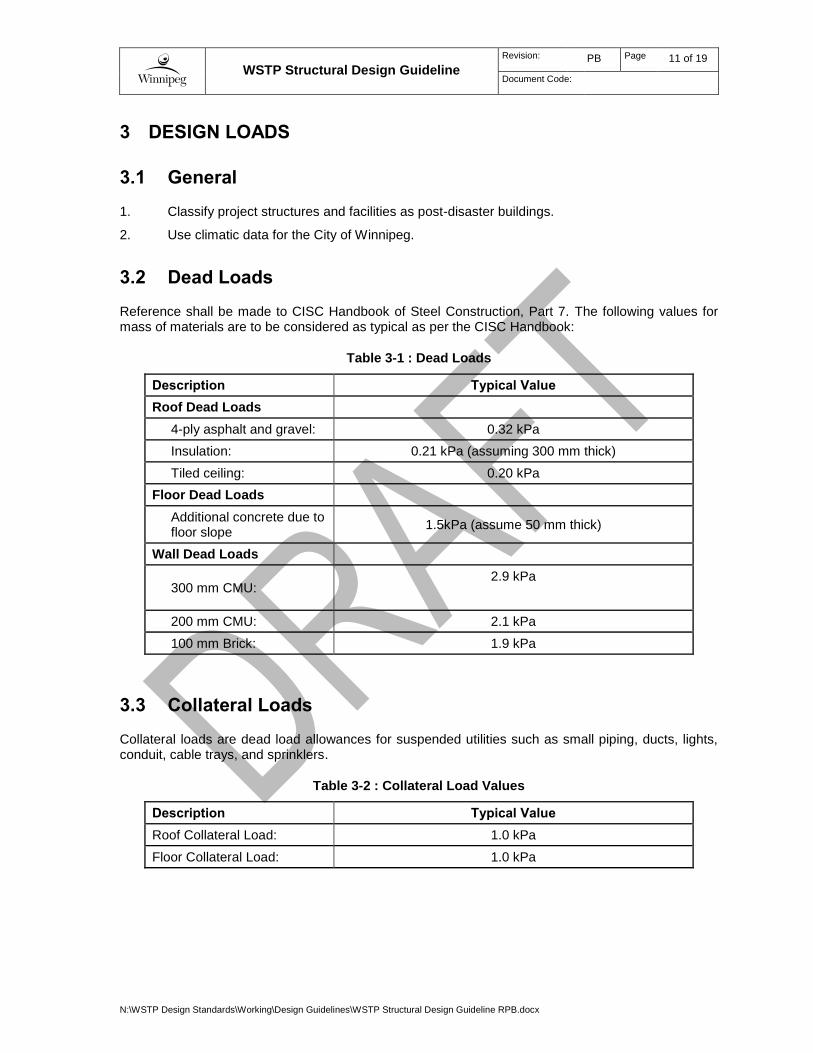
3.2 Dead Loads
Reference shall be made to CISC Handbook of Steel Construction, Part 7. The following values for mass of materials are to be considered as typical as per the CISC Handbook:
Table 3-1 : Dead Loads
Description Typical Value
Roof Dead Loads
4-ply asphalt and gravel: 0.32 kPa
Insulation: 0.21 kPa (assuming 300 mm thick)
Tiled ceiling: 0.20 kPa
Floor Dead Loads
Additional concrete due to floor slope
1.5kPa (assume 50 mm thick)
Wall Dead Loads
300 mm CMU: 2.9 kPa
200 mm CMU: 2.1 kPa
100 mm Brick: 1.9 kPa
3.3 Collateral Loads
Collateral loads are dead load allowances for suspended utilities such as small piping, ducts, lights, conduit, cable trays, and sprinklers.
Table 3-2 : Collateral Load Values
Description Typical Value
Roof Collateral Load: 1.0 kPa
Floor Collateral Load: 1.0 kPa

WSTP Structural Design Guideline
Revision: PB Page 12 of 19
Document Code:
N:\WSTP Design Standards\Working\Design Guidelines\WSTP Structural Design Guideline RPB.docx
3.4 Live Loads
Table 3-3 : Live Load Values
Description Typical Value
Roof Live Load (not including snow): 1 kPa min
Electrical Rooms: 15 kPa (see Note 1)
Grating, Checkered Plate and Hatch Covers:
Same as surrounding floor area, 5 kPa minimum
Mechanical Rooms: 10 kPa (see Note 1)
Process Areas (slabs, beams, and girders): 15 kPa (see Note 1)
Process Areas (columns and foundations): 10 kPa (see Note 1)
Office and Laboratory Areas: 5 kPa
Stairs, Landings, Platforms, and Corridors: 5 kPa
Storage Areas: Actual stored weight, 10 kPa minimum
Unrestricted Vehicular Areas: HS 20-44
Notes:
1. In addition to designing for this minimum uniform load, the engineer will design structure to support actual equipment and tank loads. Where this minimum uniform load is not possible (i.e., in existing spaces), the maximum allowable load shall be noted on drawings.
2. See Impact Loads and Other Machinery Loads for other equipment related live loads.
3.5 Seismic Loads
Per Manitoba amendments to the NBC, specifically pertaining to Section 4.1.8.1, the value of Sa(0.2) = 0. Therefore, the seismic loads can be ignored.
WSTP Structural Design Guideline
Revision: PB Page 13 of 19
Document Code:
N:\WSTP Design Standards\Working\Design Guidelines\WSTP Structural Design Guideline RPB.docx
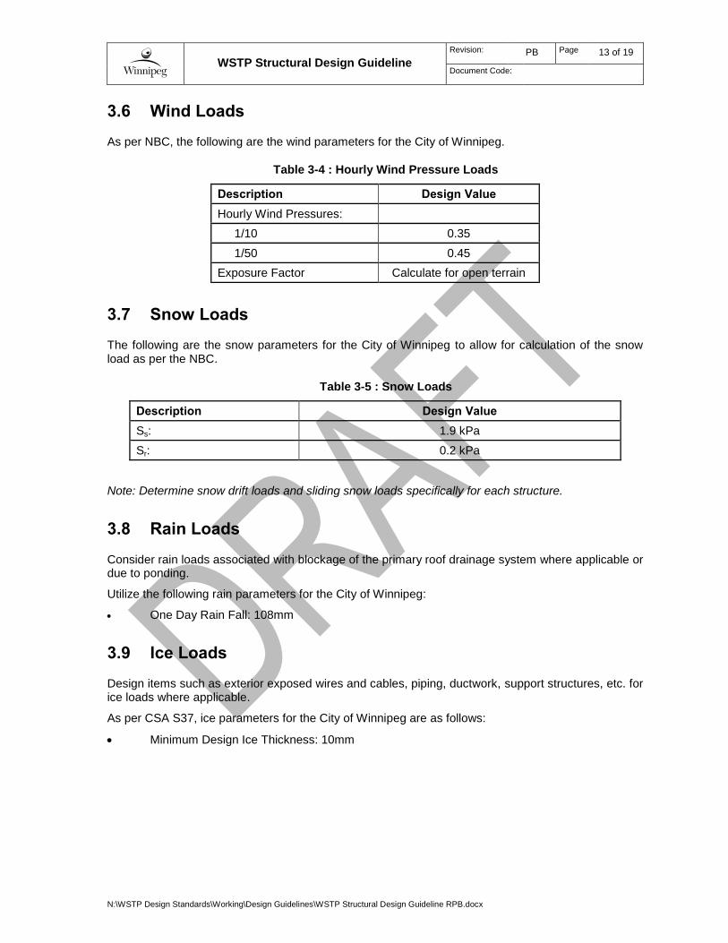
3.6 Wind Loads
As per NBC, the following are the wind parameters for the City of Winnipeg.
Table 3-4 : Hourly Wind Pressure Loads
Description Design Value
Hourly Wind Pressures:
1/10 0.35
1/50 0.45
Exposure Factor Calculate for open terrain
3.7 Snow Loads
The following are the snow parameters for the City of Winnipeg to allow for calculation of the snow load as per the NBC.
Table 3-5 : Snow Loads
Description Design Value
Ss: 1.9 kPa
Sr: 0.2 kPa
Note: Determine snow drift loads and sliding snow loads specifically for each structure.
3.8 Rain Loads
Consider rain loads associated with blockage of the primary roof drainage system where applicable or due to ponding.
Utilize the following rain parameters for the City of Winnipeg:
One Day Rain Fall: 108mm
3.9 Ice Loads
Design items such as exterior exposed wires and cables, piping, ductwork, support structures, etc. for ice loads where applicable.
As per CSA S37, ice parameters for the City of Winnipeg are as follows:
Minimum Design Ice Thickness: 10mm

WSTP Structural Design Guideline
Revision: PB Page 14 of 19
Document Code:
N:\WSTP Design Standards\Working\Design Guidelines\WSTP Structural Design Guideline RPB.docx
3.10 Impact Loads
Confirm equipment loading, including any impact loads due to equipment, with data sheets requested from the manufacturers.
Table 3-6 : Impact Loads
Description Design Value
Light machinery (shaft or motor driven):
Increased load by 20 percent minimum or manufacturer’s recommendation for impact, whichever is greater.
Reciprocating machinery or power-driven unit:
Increase loads by 50 percent minimum or manufacturer’s recommendations for impact, whichever is greater.
Torsional and thrust force: Obtain maximum torsional and thrust forces from vertical turbines from equipment manufacturer. Identify any other torsional and thrust forces.
Vertical impact due to lifting devices:
The maximum wheel loads of the crane shall be increased by the following percentages:
Cab operated, or radio-operated cranes (powered): 25 percent
Pendant or hand-operated cranes: 10 percent
Lateral force due to cranes:
The lateral force applied perpendicular to the crane runway beams shall be calculated as 20 percent of the sum of the rated capacity of crane and the weight of the hoist and trolley.
Longitudinal force due to cranes:
The longitudinal force on crane runway beams shall be calculated as 10 percent of the maximum wheel loads of the crane.
3.11 Thermal Loads
Consider thermal loads for facilities with structural members that will be permanently exposed or partially exposed to exterior condition.
Design temperature range for the City of Winnipeg:
Table 3-7 : Thermal Loads
Description Design Value
Temperature Range -33 °C to +30 °C
WSTP Structural Design Guideline
Revision: PB Page 15 of 19
Document Code:
N:\WSTP Design Standards\Working\Design Guidelines\WSTP Structural Design Guideline RPB.docx
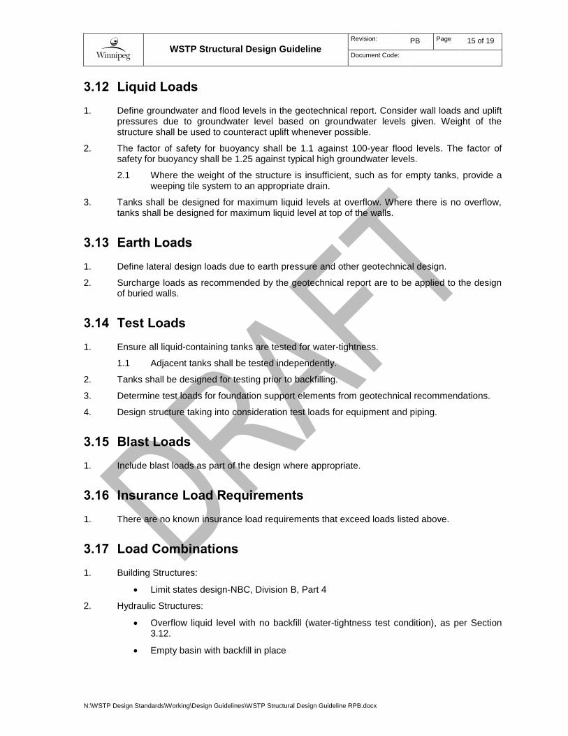
3.12 Liquid Loads
1. Define groundwater and flood levels in the geotechnical report. Consider wall loads and uplift pressures due to groundwater level based on groundwater levels given. Weight of the structure shall be used to counteract uplift whenever possible.
2. The factor of safety for buoyancy shall be 1.1 against 100-year flood levels. The factor of safety for buoyancy shall be 1.25 against typical high groundwater levels.
2.1 Where the weight of the structure is insufficient, such as for empty tanks, provide a weeping tile system to an appropriate drain.
3. Tanks shall be designed for maximum liquid levels at overflow. Where there is no overflow, tanks shall be designed for maximum liquid level at top of the walls.
3.13 Earth Loads
1. Define lateral design loads due to earth pressure and other geotechnical design.
2. Surcharge loads as recommended by the geotechnical report are to be applied to the design of buried walls.
3.14 Test Loads
1. Ensure all liquid-containing tanks are tested for water-tightness.
1.1 Adjacent tanks shall be tested independently.
2. Tanks shall be designed for testing prior to backfilling.
3. Determine test loads for foundation support elements from geotechnical recommendations.
4. Design structure taking into consideration test loads for equipment and piping.
3.15 Blast Loads
1. Include blast loads as part of the design where appropriate.
3.16 Insurance Load Requirements
1. There are no known insurance load requirements that exceed loads listed above.
3.17 Load Combinations
1. Building Structures:
Limit states design-NBC, Division B, Part 4
2. Hydraulic Structures:
Overflow liquid level with no backfill (water-tightness test condition), as per Section 3.12.
Empty basin with backfill in place

WSTP Structural Design Guideline
Revision: PB Page 16 of 19
Document Code:
N:\WSTP Design Standards\Working\Design Guidelines\WSTP Structural Design Guideline RPB.docx
3.18 Deflection Criteria
Table 3-8 : Deflection Criteria
Description Load Type Design Value
(Maximum)
Roof Members
Dead+ Live L/240
Live Only L/360
Snow Only L/360
Floor Members Dead+ Live L/240
Live Only L/360
Steel Floor Plates and Grating Live L/360
Crane Suspension Systems
Monorail Crane Dead+ Live L/800
Bridge Crane Dead+ Live L/1000
Beams and Lintels Supporting Masonry
Vertical Support Dead+ Live Lesser of L/720 or 8 mm
Structural Members bracing out-of-plane loads Dead+ Live L/360
Exterior Walls and Interior Partitions Live, Snow, or
Wind L/240
3.19 Vibration Design Criteria
1. Consult equipment manufacturers for vibration-related information such as frequencies, unbalanced loads, use of vibration isolators or dampeners, and support requirements.
2. Mount all rotating equipment that produces vibrations of sufficient magnitude on concrete foundations or concrete support systems.
3. Design the concrete support and surrounding structure such that the natural frequency shall be less than 0.5 times or more than 1.5 times the normal operating frequency of the equipment. Special consideration shall be given to variable frequency equipment.
4. Where vibration is significant, anchorage to concrete foundations shall be by embedded anchor bolts, not post installed anchors

WSTP Structural Design Guideline
Revision: PB Page 17 of 19
Document Code:
N:\WSTP Design Standards\Working\Design Guidelines\WSTP Structural Design Guideline RPB.docx
3.20 Structural System Requirements
Ensure new materials that will be used will meet the following criteria:
Table 3-9 : Structural System Requirements
Description Requirement
Concrete Exposure Class S-2 or S-3
Concrete Masonry CSA A165
Reinforcing Steel (unless otherwise noted) CAN/CSA G30.18, Grade 400(R)
Structural Steel (unless otherwise noted)
CAN/CSA G40.21, Grade 350W
Anchor Bolts ASTM A 307
Structural Bolted Connections ASTM A 325
Stainless Steel AISI, Type 316
Aluminum Alloy 6061-T6 or 6351-T6
Note:
1. Ensure that all materials utilized are compatible with the specific environment within the building or process area, including consideration for all chemicals utilized.

WSTP Structural Design Guideline
Revision: PB Page 18 of 19
Document Code:
N:\WSTP Design Standards\Working\Design Guidelines\WSTP Structural Design Guideline RPB.docx
4 MAINTENANCE AND SAFETY
4.1 Maintenance
1. Provide appropriate lifting devices to allow for maintenance and removal of equipment. Coordinate with other disciplines as required.
2. All permanent lifting devices shall be designed and detailed by the design engineer. Design responsibility shall not be deferred to the contractor except when using a design-build procurement model.
4.2 Safety
1. Provide systems to accommodate safe access to all areas of the facility, including tanks, conduits, and channels. Minimum requirements include, but are not limited to the following:
1.1 Where practical, provide embedded safety davit bases to accommodate a portable safety davit to allow for save personnel access to tanks, conduit, and channels.
1.2 Surface mount davits may be utilized where embedded davit bases are not acceptable.
1.3 Provide permanent ladders where portable ladders are not effective or where personnel access is frequent (> once per month).
WSTP Structural Design Guideline
Revision: PB Page 19 of 19
Document Code:
N:\WSTP Design Standards\Working\Design Guidelines\WSTP Structural Design Guideline RPB.docx
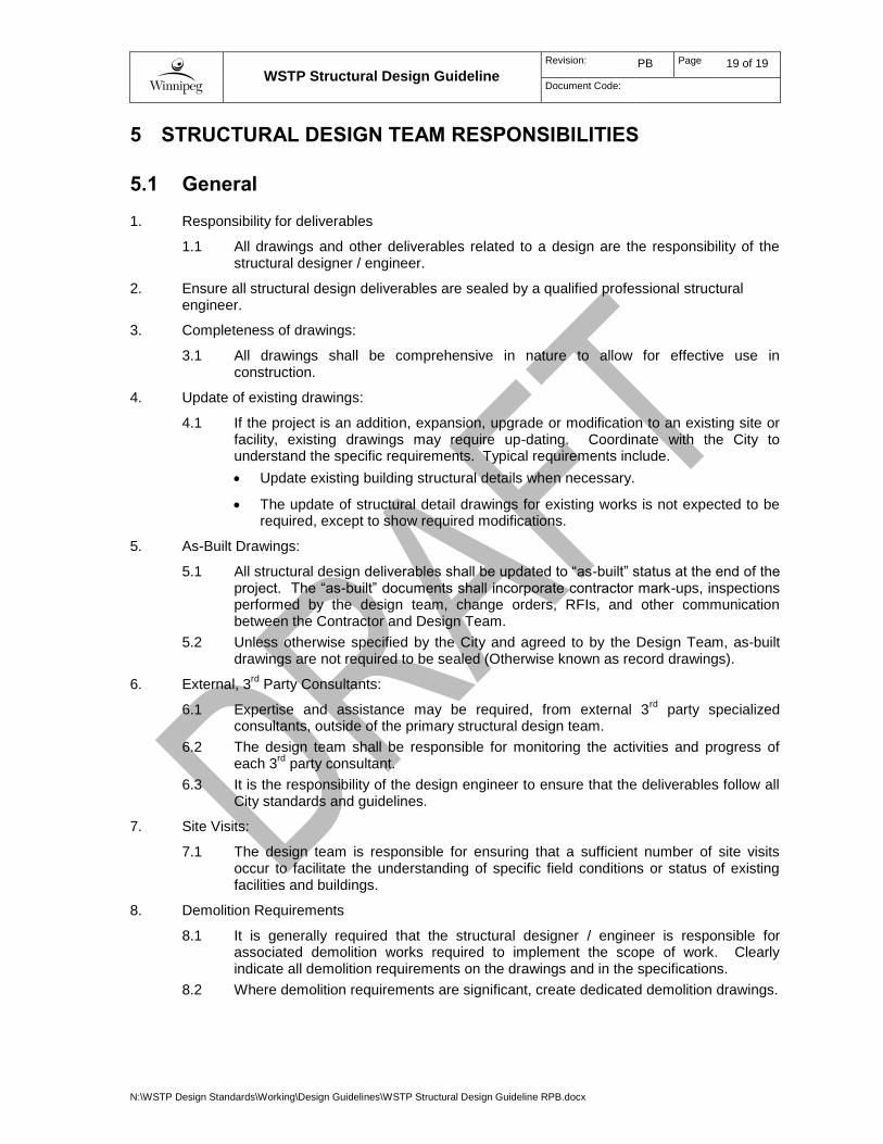
5 STRUCTURAL DESIGN TEAM RESPONSIBILITIES
5.1 General
1. Responsibility for deliverables
1.1 All drawings and other deliverables related to a design are the responsibility of the structural designer / engineer.
2. Ensure all structural design deliverables are sealed by a qualified professional structural engineer.
3. Completeness of drawings:
3.1 All drawings shall be comprehensive in nature to allow for effective use in construction.
4. Update of existing drawings:
4.1 If the project is an addition, expansion, upgrade or modification to an existing site or facility, existing drawings may require up-dating. Coordinate with the City to understand the specific requirements. Typical requirements include.
Update existing building structural details when necessary.
The update of structural detail drawings for existing works is not expected to be required, except to show required modifications.
5. As-Built Drawings:
5.1 All structural design deliverables shall be updated to “as-built” status at the end of the project. The “as-built” documents shall incorporate contractor mark-ups, inspections performed by the design team, change orders, RFIs, and other communication between the Contractor and Design Team.
5.2 Unless otherwise specified by the City and agreed to by the Design Team, as-built drawings are not required to be sealed (Otherwise known as record drawings).
6. External, 3rd
Party Consultants:
6.1 Expertise and assistance may be required, from external 3rd
party specialized consultants, outside of the primary structural design team.
6.2 The design team shall be responsible for monitoring the activities and progress of each 3
rd party consultant.
6.3 It is the responsibility of the design engineer to ensure that the deliverables follow all City standards and guidelines.
7. Site Visits:
7.1 The design team is responsible for ensuring that a sufficient number of site visits occur to facilitate the understanding of specific field conditions or status of existing facilities and buildings.
8. Demolition Requirements
8.1 It is generally required that the structural designer / engineer is responsible for associated demolition works required to implement the scope of work. Clearly indicate all demolition requirements on the drawings and in the specifications.
8.2 Where demolition requirements are significant, create dedicated demolition drawings.

WSTP Structural Design Guideline
Revision: PB Page 20 of 19
Document Code:
N:\WSTP Design Standards\Working\Design Guidelines\WSTP Structural Design Guideline RPB.docx
5.2 Drawings
Provide a comprehensive set of drawings to detail the structural construction requirements. The drawings indicated in this section are minimum requirements for new construction, unless otherwise approved by the City.
5.2.1 General Requirements
1. All structural drawings are to be produced on a standard A1 size drawing.
2. All structural drawings shall be to scale.
3. All dimensions required for construction shall be shown.
4. Indicate north direction on all plan drawings.
5. Provide scale bars on drawings to allow for simplified scale takeoff on the drawings.
6. Differentiate new work from existing work via bold lines.
5.2.2 Legend
1. Provide a legend drawing showing the symbols and abbreviations utilized. Ensure that the legend is consistent with the City’s practices and other disciplines.
5.2.3 General Notes Drawing
1. Provide a general notes drawing for each type of structure.
2. Content
2.1 Include general construction notes.
2.2 Provide building design criteria including key design loads
2.3 Provide foundation design criteria.
2.4 Provide concrete requirements.
2.5 Provide concrete reinforcing requirements.
2.6 Provide masonry requirements as applicable.
2.7 Provide structural steel and metal fabrication requirements.
5.2.4 Foundation / Piling Drawings
1. Provide detailed foundation / piling drawings comprehensive of all new and modified areas.
2. Content
2.1 To be developed.
5.2.5 Pile Schedule and Details
1. Provide pile schedule and detail drawings where piles are utilized.
2. Content
2.1 To be developed.

WSTP Structural Design Guideline
Revision: PB Page 21 of 19
Document Code:
N:\WSTP Design Standards\Working\Design Guidelines\WSTP Structural Design Guideline RPB.docx
5.2.6 Structural Plan Drawings
1. Provide detailed structural plan drawings comprehensive of all new and modified areas.
2. Content
2.1 To be developed.
5.2.7 Structural Section and Detail Drawings
1. Provide detailed structural section and detail drawings comprehensive of all new and modified areas to completely define the required work.
2. Content
2.1 To be developed.
5.2.8 Concrete Reinforcing Drawings
1. Provide a comprehensive set of drawings to fully detail the concrete reinforcing requirements,
2. Content
2.1 To be developed.
5.2.9 Detail Drawings
1. Detail drawings shall include, but not be limited to:
1.1 Access hatch configuration, including dimensions, hinge and handle configuration, sill configuration, and materials.
1.2 Concrete embeds such as studded anchor plates and angles to support masonry veneers, process beams, slabs and girders.
1.3 Monorail hoists, bridge cranes, large diameter piping supports, structural steel stair cases in stair wells, etc.
1.4 Guardrail, ladder, and gate details including dimensions and detailed layout.
2. Content
2.1 To be developed.
5.2.10 3D Model
1. When 3D design is required by the City, or proposed by the Consultant, this section shall be complied with in its entirety. 3D models and associated drawings are not mandatory for all projects.
2. The 3D model shall include all structural elements (other than concrete reinforcing) to allow for full representation of the entire facility, including all other disciplines.
3. In addition to the 3D model provide:
3.1 3D elevation and section drawings to convey the complete structural configuration.
3.2 3D detail drawings of all areas with significant interdisciplinary coordination requirements.

WSTP Structural Design Guideline
Revision: PB Page 22 of 19
Document Code:
N:\WSTP Design Standards\Working\Design Guidelines\WSTP Structural Design Guideline RPB.docx
5.3 Structural Design Calculations
1. Provide detailed design calculations in accordance with the relevant codes and authorized local and national bodies taking into account the most unfavorable condition of dead load, live load, wind load, construction load etc. for all structures. Design calculations shall be submitted with the design drawings as part of the review cycle to allow for parallel review.