the city of · pdf filethe city of winnipeg ... 4.6 cross-connection control ... \wstp design...
TRANSCRIPT
Revision: PB Page 1 of 19—. WSTP Building Mechanical Design Guideline
‘Winnipeg Document Code:
Wrnmpeg
The City of Winnipeg
Winnipeg Sewage Treatment Program
Building Mechanical Design Guideline
Document Code:
Revision: PB
Approved By:
Duaie Griffin, BrarWastewater Planning Delivery
N:\WSTP Design Standards\Working\Design Guidelines\WSTP Building Mechanical Design Guideline RPB.docx

WSTP Building Mechanical Design Guideline
Revision: PB Page 3 of 19
Document Code:
N:\WSTP Design Standards\Working\Design Guidelines\WSTP Building Mechanical Design Guideline RPB.docx
REVISION REGISTER
Rev. Description Date By Approved
PA Issued for draft review 2015-05-29 C. Reimer / K.
Anwar
PB Issued for Inclusion in RFPs 2015-06-05 C. Reimer
CAUTION
This document is currently in a draft state. All design shall be based upon the approved issue of this document, which will be provided prior to award.
WSTP Building Mechanical Design Guideline
Revision: PB Page 4 of 19
Document Code:
N:\WSTP Design Standards\Working\Design Guidelines\WSTP Building Mechanical Design Guideline RPB.docx
This page is intentionally blank.
WSTP Building Mechanical Design Guideline
Revision: PB Page 5 of 19
Document Code:
N:\WSTP Design Standards\Working\Design Guidelines\WSTP Building Mechanical Design Guideline RPB.docx
Table of Contents
1 Introduction ................................................................................................... 7
1.1 Scope of the Standard .................................................................................................. 7 1.2 Application .................................................................................................................... 7 1.3 Deviations from Standard ............................................................................................. 7 1.4 Acronyms and Abbreviations ........................................................................................ 8
2 General ........................................................................................................... 9
2.1 Design Codes and Standards ...................................................................................... 9 2.2 Referenced Standards .................................................................................................. 9 2.3 Other City Standards .................................................................................................... 9 2.4 Units ............................................................................................................................ 10
3 HVAC systems ............................................................................................. 11
3.1.1 General Requirements .................................................................................. 11 3.2 Design Parameters ..................................................................................................... 11
3.2.1 Outdoor Design Parameters .......................................................................... 11 3.2.2 Indoor Temperature ....................................................................................... 12 3.2.3 Humidity Control Criteria ............................................................................... 12 3.2.4 Noise Criteria ................................................................................................. 13
3.3 Space Pressurization .................................................................................................. 13 3.4 Design Requirements ................................................................................................. 13
3.4.1 Application of NFPA 820 ............................................................................... 13 3.4.2 General Ventilation Requirements ................................................................ 14 3.4.3 Equipment Redundancy ................................................................................ 14 3.4.4 Heating Systems ........................................................................................... 15 3.4.5 Heat Recovery ............................................................................................... 15 3.4.6 Air Conditioning System ................................................................................ 15
3.5 Equipment and Material Design Requirements .......................................................... 15 3.5.1 General Layout Requirements ...................................................................... 15 3.5.2 Outdoor Air Filtration Criteria ......................................................................... 16 3.5.3 HVAC Equipment Selection Criteria .............................................................. 16 3.5.4 Ductwork ........................................................................................................ 17
3.6 HVAC System Monitoring and Controls ..................................................................... 17 3.6.1 HVAC Controls .............................................................................................. 17 3.6.2 Gas Detection ................................................................................................ 18
4 plumbing systems ....................................................................................... 20
4.1 Plumbing System Concepts ....................................................................................... 20 4.2 Insulated Plumbing Piping .......................................................................................... 21 4.3 Plumbing Fixtures ....................................................................................................... 21 4.4 Emergency Safety Equipment .................................................................................... 21 4.5 Water Conservation .................................................................................................... 21 4.6 Cross-Connection Control .......................................................................................... 22 4.7 Plumbing Equipment .................................................................................................. 22
5 Fire Protection Systems ............................................................................. 23
WSTP Building Mechanical Design Guideline
Revision: PB Page 6 of 19
Document Code:
N:\WSTP Design Standards\Working\Design Guidelines\WSTP Building Mechanical Design Guideline RPB.docx
6 Building Mechanical Design Team Responsibilities ................................ 24
6.1 General ....................................................................................................................... 24 6.2 Drawings ..................................................................................................................... 25
6.2.1 Legend ........................................................................................................... 25 6.2.2 Process and Instrumentation Diagrams ........................................................ 25 6.2.3 Schematic Airflow Diagram ........................................................................... 26 6.2.4 Building Mechanical Plan Drawings .............................................................. 26 6.2.5 Building Mechanical Section and Detail Drawings ........................................ 26 6.2.6 Schedule Drawings ........................................................................................ 27 6.2.7 Pipe Work Layout Drawings .......................................................................... 27 6.2.8 Fire Fighting Layout Drawings ....................................................................... 27 6.2.9 Installation Detail Drawings ........................................................................... 27 6.2.10 3D Model ....................................................................................................... 28 6.2.11 Coordination with Other Disciplines .............................................................. 28
6.3 Design Calculations .................................................................................................... 29

WSTP Building Mechanical Design Guideline
Revision: PA Page 7 of 19
Document Code:
N:\WSTP Design Standards\Working\Design Guidelines\WSTP Building Mechanical Design Guideline RPB.docx
1 INTRODUCTION
This document identifies the standard building mechanical design requirements that are applicable to any work within the City of Winnipeg wastewater treatment facilities.
1.1 Scope of the Standard
These design requirements shall apply to the following facilities:
Wastewater treatment plants
1.2 Application
The scope and intent of this document is intended to convey general design guidance and expectations regarding building mechanical systems. This document does address specifics related to design type, selection, and configuration; however the indicated requirements are presented without knowledge of the specific building mechanical system implementation. It is not within the scope of this document to provide detailed design direction, and it will be the responsibility of the respective building mechanical and HVAC designers to fully develop the system details with general conformance to the concepts presented herein. This standard shall not be construed as comprehensive engineering design requirements or negate the requirement for professional engineering involvement. Any design must be executed under the responsibility and seal of the engineer in each instance, and must be performed in conformance with all applicable codes and standards, as well as good engineering practice.
Existing facilities do not necessarily comply with this standard. The expectations regarding application of this standard to maintenance and minor upgrades at existing facilities must be assessed on a case-by-case basis; however general guidelines for application are presented as follows:
All new buildings are expected to comply with this standard.
All major upgrades to a building are expected to comply with this standard; however in some cases compromise with the configuration of the existing facility design may be required.
All minor upgrades should utilize this standard as far as practical for new work; however in some cases compromise with the configuration of the existing facility design may be required.
1.3 Deviations from Standard
It is expected that there will be occasional situations where the design architect / engineer will propose a deviation from this design guideline. The rational for potential deviations from the design guideline may include:
Evolution of technology,
Updates to standards and regulations,
Practical limitations due to existing conditions on site, or
Significant cost benefits to the City due to specific project constraints.
For each proposed deviation from this standard, fully complete a WSTP Standards Deviation Form and submit to the City project manager for approval. Do not proceed with the proposed deviation unless approval is received from the City project manager.

WSTP Building Mechanical Design Guideline
Revision: PB Page 8 of 19
Document Code:
N:\WSTP Design Standards\Working\Design Guidelines\WSTP Building Mechanical Design Guideline RPB.docx
1.4 Acronyms and Abbreviations
AHU Air Handling Unit
ANSI American National Standards Institute
ASHRAE American Society of Heating, Refrigerating, and Air Conditioning Engineers
CGA Canadian Gas Association
CSA Canadian Standards Association
CO Carbon Monoxide
DX Direct Expansion
FRP Fiber Reinforced Plastic
H2S Hydrogen Sulphide
HVAC Heating Ventilation and Cooling
MAU Make-up Air Unit
MCC Motor Control Center
MERV Minimum Efficiency Reporting Value
NBC National Building Code
NFC National Fire Code
NFPA National Fire Protection Association
PLC Programmable Logic Controller
RH Relative Humidity
PCS Process Control System
SMACNA Sheet Metal and Air Conditioning Contractors National Association
UL Underwriters Laboratory, Inc.
VFD Variable Frequency Drive
WSTP Winnipeg Sewage Treatment Program
WSTP Building Mechanical Design Guideline
Revision: PB Page 9 of 19
Document Code:
N:\WSTP Design Standards\Working\Design Guidelines\WSTP Building Mechanical Design Guideline RPB.docx
2 GENERAL
2.1 Design Codes and Standards
Ensure all designs shall comply with municipal, provincial, and national codes and bylaws. This includes but is not limited to:
National Building Code of Canada with Manitoba Building Code Amendments
National Energy Code of Canada for Buildings 2011
National Fire Code of Canada Province of Manitoba Workplace Health and Safety Act
City of Winnipeg WWD Hydrogen Sulphide Monitoring Program
National Plumbing Code of Canada with Manitoba Plumbing Code Amendments
Canadian Gas Association (CGA): CSA/CGA B149.1-10 Natural Gas and Propane Installation Code
ANSI Z358.1-2009, Standard for Emergency Eyewash and Shower Equipment
CSA B64.4-11 Reduced Pressure Principle (RP) Backflow Preventers
CSA B64.5-11 Double Check Valve (DCVA) Backflow Preventers
2.2 Referenced Standards
The application of NFPA 820 Standard for Fire Protection in Wastewater Treatment and Collection Facilities shall be as per Section 3.4.1.
The following standards are to be referenced during the design; however application of these standards will not necessarily be comprehensive:
ASHRAE Standard 62.1 Ventilation for Acceptable Indoor Air Quality
NFPA 90A Standard for the Installation of Air Conditioning and Ventilation Systems
ASHRAE Standard 90.1 for building energy efficiency
2.3 Other City Standards
1. While not exclusive, ensure that the following City Standards are adhered to:
1.1 Water and Waste Department Identification Standard

WSTP Building Mechanical Design Guideline
Revision: PB Page 10 of 19
Document Code:
N:\WSTP Design Standards\Working\Design Guidelines\WSTP Building Mechanical Design Guideline RPB.docx
2.4 Units
All drawings and documentation shall use the International System of Units (SI units). Imperial units may be provided in parenthesis after the metric unit, where requested or appropriate. Specific requirements are as follows:
1. All building dimensions shall be in millimeters.
2. All elevations shall be in meters, in the format EL. ###.### (example EL. 273.520)
3. All liquid flow rates shall be in one of the two following units:
3.1 Large flows in m3/hr
3.2 Small flows in l/s.
4. All airflow rates shall to be in l/s.
5. All liquid pressures shall be in kPa (kilopascals).
6. All HVAC air pressures shall in Pa (Pascals).
WSTP Building Mechanical Design Guideline
Revision: PB Page 11 of 19
Document Code:
N:\WSTP Design Standards\Working\Design Guidelines\WSTP Building Mechanical Design Guideline RPB.docx
3 HVAC SYSTEMS
3.1.1 General Requirements
1. General design concept for the entire system shall be well defined.
2. Ensure each system is designed to be complete in every respect for a trouble free operation, including AHU’s, fans, pumps, expansion units, ducting, refrigerant and drain piping, thermal and vapor insulation for ducts and pipes, grilles, registers, diffusers, louvers, dampers, sound attenuators, vibration isolators, air coolers, electric air heaters, air filters, etc.
3. Ensure design takes into consideration sufficient redundancy capacities and safety margins.
3.2 Design Parameters
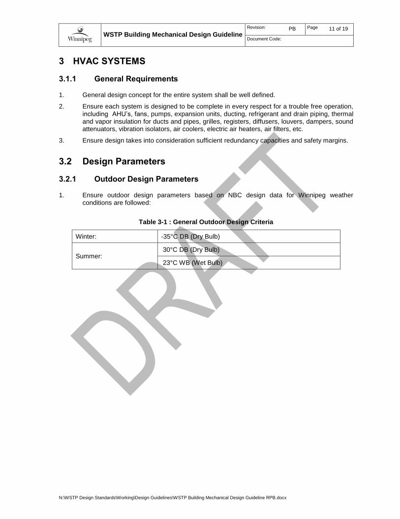
3.2.1 Outdoor Design Parameters
1. Ensure outdoor design parameters based on NBC design data for Winnipeg weather conditions are followed:
Table 3-1 : General Outdoor Design Criteria
Winter: -35°C DB (Dry Bulb)
Summer: 30°C DB (Dry Bulb)
23°C WB (Wet Bulb)
WSTP Building Mechanical Design Guideline
Revision: PB Page 12 of 19
Document Code:
N:\WSTP Design Standards\Working\Design Guidelines\WSTP Building Mechanical Design Guideline RPB.docx
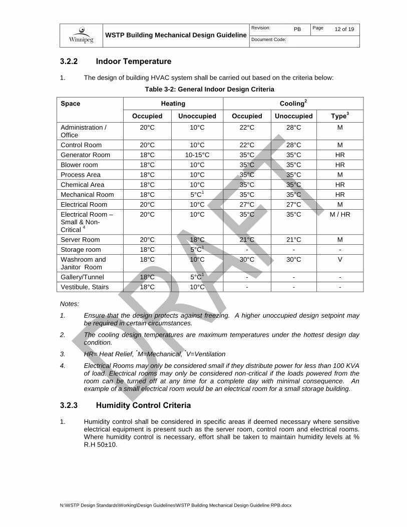
3.2.2 Indoor Temperature
1. The design of building HVAC system shall be carried out based on the criteria below:
Table 3-2: General Indoor Design Criteria
Space Heating Cooling2
Occupied Unoccupied Occupied Unoccupied Type3
Administration / Office
20°C 10°C 22°C 28°C M
Control Room 20°C 10°C 22°C 28°C M
Generator Room 18°C 10-15°C 35°C 35°C HR
Blower room 18°C 10°C 35°C 35°C HR
Process Area 18°C 10°C 35°C 35°C M
Chemical Area 18°C 10°C 35°C 35°C HR
Mechanical Room 18°C 5°C1 35°C 35°C HR
Electrical Room 20°C 10°C 27°C 27°C M
Electrical Room – Small & Non-Critical
4
20°C 10°C 35°C 35°C M / HR
Server Room 20°C 18°C 21°C 21°C M
Storage room 18°C 5°C1 - - -
Washroom and Janitor Room
18°C 10°C 30°C 30°C V
Gallery/Tunnel 18°C 5°C1 - - -
Vestibule, Stairs 18°C 10°C - - -
Notes:
1. Ensure that the design protects against freezing. A higher unoccupied design setpoint may be required in certain circumstances.
2. The cooling design temperatures are maximum temperatures under the hottest design day condition.
3. HR= Heat Relief, *M=Mechanical,
*V=Ventilation
4. Electrical Rooms may only be considered small if they distribute power for less than 100 KVA of load. Electrical rooms may only be considered non-critical if the loads powered from the room can be turned off at any time for a complete day with minimal consequence. An example of a small electrical room would be an electrical room for a small storage building.
3.2.3 Humidity Control Criteria
1. Humidity control shall be considered in specific areas if deemed necessary where sensitive electrical equipment is present such as the server room, control room and electrical rooms. Where humidity control is necessary, effort shall be taken to maintain humidity levels at % R.H 50±10.

WSTP Building Mechanical Design Guideline
Revision: PB Page 13 of 19
Document Code:
N:\WSTP Design Standards\Working\Design Guidelines\WSTP Building Mechanical Design Guideline RPB.docx
3.2.4 Noise Criteria
1. Refer and adhere to the noise control criteria as defined in the WSTP Architectural Design Guideline.
1.1 Provide noise attenuation such as acoustical enclosures when the equipment has a high noise level and is located in a regularly accessed area which would impact on operations. It shall be noted that fan selection shall not be based solely on noise generation.
2. Ensure that the air handling unit or make-up air unit is equipped with internal vibration isolators or pads and insulation on casing.
3. Provide duct silencers for the exhaust/supply fans if required to maintain the HVAC equipment noise level.
4. Provide silencers for generator rooms and blower room air intake and exhaust louvers to meet the design criteria.
5. Reference manufacturer specified noise levels to confirm that they meet or exceed the limits noted above.
3.3 Space Pressurization
1. Ensure in general that negative pressure (approx. -25 Pascal) is maintained for process areas where odour or off-gas occurs in accordance with NFPA 820.
2. Ensure ventilation systems serving the control rooms, electrical rooms and administration office area keep a positive pressure of roughly 25 Pascal under all operating conditions.
3.4 Design Requirements
3.4.1 Application of NFPA 820
1. Application of NFPA 820 shall be comprehensive, except as approved by the City during the preliminary design phase of a project.
2. Preliminary design stage:
2.1 During the preliminary design stage, review and make recommendations regarding the application of NFPA 820 to the project. Review the lifecycle capital and operating costs for the proposed ventilation rate and associated electrical classification.
2.1.1 Consider heating costs in the application of NFPA 820.
2.1.2 Propose ventilation rates to the City for review, along with corresponding annual heating costs.
2.1.3 Review the proposed ventilation strategy with the City and implement as per City direction.
2.2 For design-build projects, all work shall fully comply with NFPA 820, unless specifically indicated otherwise in the Contract.
3. Electrical classification vs. ventilation:
3.1 For many spaces, NFPA 820 permits a lower ventilation rate provided that a higher level of electrical classification is provided. The higher ventilation rate and lower electrical classification shall be utilized in all cases, except as follows:
WSTP Building Mechanical Design Guideline
Revision: PB Page 14 of 19
Document Code:
N:\WSTP Design Standards\Working\Design Guidelines\WSTP Building Mechanical Design Guideline RPB.docx
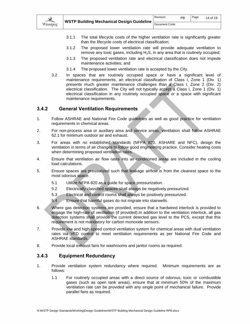
3.1.1 The total lifecycle costs of the higher ventilation rate is significantly greater than the lifecycle costs of electrical classification;
3.1.2 The proposed lower ventilation rate will provide adequate ventilation to remove any toxic gases, including H2S, in any area that is routinely occupied;
3.1.3 The proposed ventilation rate and electrical classification does not impede maintenance activities; and
3.1.4 The proposed lower ventilation rate is accepted by the City.
3.2 In spaces that are routinely occupied space or have a significant level of maintenance requirements, an electrical classification of Class I, Zone 1 (Div. 1) presents much greater maintenance challenges than a Class I, Zone 2 (Div. 2) electrical classification. The City will not typically accept a Class I, Zone 1 (Div. 1) electrical classification in any routinely occupied space or a space with significant maintenance requirements.
3.4.2 General Ventilation Requirements
1. Follow ASHRAE and National Fire Code guidelines as well as good practice for ventilation requirements in chemical areas.
2. For non-process area or auxiliary area and service areas, ventilation shall follow ASHRAE 62.1 for minimum outdoor air and exhaust.
3. For areas with no established standards (NFPA 820, ASHARE and NFC), design the ventilation in terms of air changes to follow good engineering practice. Consider heating costs when determining proposed ventilation rates.
4. Ensure that ventilation air flow rates into air-conditioned areas are included in the cooling load calculations.
5. Ensure spaces are pressurized such that leakage airflow is from the cleanest space to the most odorous space.
5.1 Utilize NFPA 820 as a guide for space pressurization.
5.2 Electrically classified spaces shall always be negatively pressurized.
5.3 Electrical and control rooms shall always be positively pressurized.
5.4 Ensure that harmful gases do not migrate into stairwells.
6. Where gas detection systems are provided, ensure that a hardwired interlock is provided to engage the high-rate of ventilation (if provided).In addition to the ventilation interlock, all gas detection systems shall provide the current detected gas level to the PCS, except that this requirement is not mandatory for carbon monoxide sensors.
7. Provide low and high speed control ventilation system for chemical areas with dual ventilation rates via VFD control to meet ventilation requirements as per National Fire Code and ASHRAE standards.
8. Provide local exhaust fans for washrooms and janitor rooms as required.
3.4.3 Equipment Redundancy
1. Provide ventilation system redundancy where required. Minimum requirements are as follows:
1.1 For routinely occupied areas with a direct source of odorous, toxic or combustible gases (such as open tank areas), ensure that at minimum 50% of the maximum ventilation rate can be provided with any single point of mechanical failure. Provide parallel fans as required.

WSTP Building Mechanical Design Guideline
Revision: PB Page 15 of 19
Document Code:
N:\WSTP Design Standards\Working\Design Guidelines\WSTP Building Mechanical Design Guideline RPB.docx
1.2 For electrically classified spaces, exhaust fans shall be redundant such that at minimum 50% of the maximum design ventilation rate is provided upon exhaust fan failure. Higher level of redundancy requirements shall be evaluated on a case-by-case basis.
3.4.4 Heating Systems
1. The use of central hot water boilers to cater for the heating loads of sewage treatment facilities is preferred. In case of additions or modification to a facility, review hydronic heating systems and central boilers serving the existing facility to determine whether upgrades are warranted to accommodate the new increased heat loads.
2. Gas fired air-handlers are preferred in areas of the facility where the use of hydronic heating is not practical.
3. Electric heat may be utilized where hydronic or gas-fired heating is not practical.
3.4.5 Heat Recovery
1. Heat recovery systems shall be investigated for all systems with airflows greater than 1000 l/s. Consider both flushing water heat recover and glycol runaround loops. Other heat recovery technologies may be considered for clean-air applications.
1.1 Calculate the capital, operating and maintenance costs for the entire lifecycle of the facility. Calculate the economic payback of the heat recovery system.
1.2 Provide written recommendations to the City.
2. Unless otherwise directed by the City, provide heat recovery systems for all systems where there is an economic payback of less than ten years. Where the economic payback is greater than ten years, proceed based upon direction of the City.
3.4.6 Air Conditioning System
1. Provide DX split AC unit or air handling unit with built-in DX refrigerant coil and outdoor air-cooled condenser for control rooms, server rooms and main electrical rooms for cooling in summer to meet required indoor design temperature.
2. Size air conditioning system based on the heat gains from the electrical and control equipment in the associated space plus the ventilation loads and base loads from the building structures.
3. Ensure sufficient safety margin is taken into account in all design calculations.
3.5 Equipment and Material Design Requirements
3.5.1 General Layout Requirements
1. Ensure all equipment is accessible and has clearance to allow for maintenance.
2. Provide a minimum of 1000 mm clearance in front of all equipment.
3. For all equipment with a motor power rating of 7.5 kW (10 hp) or greater, provide a minimum clearance of 800mm between the outermost extremities of adjacent pieces of equipment, and between a wall and the equipment.
4. Provide sufficient clearances to replace air handling unit filters.
WSTP Building Mechanical Design Guideline
Revision: PB Page 16 of 19
Document Code:
N:\WSTP Design Standards\Working\Design Guidelines\WSTP Building Mechanical Design Guideline RPB.docx
5. Provide sufficient clearances to replace air handling unit coils and fans.
6. Coordinate clearances with process mechanical and electrical disciplines.
7. Locate equipment outside of corrosive locations. HVAC equipment may only be installed in corrosive locations with the approval of the City.
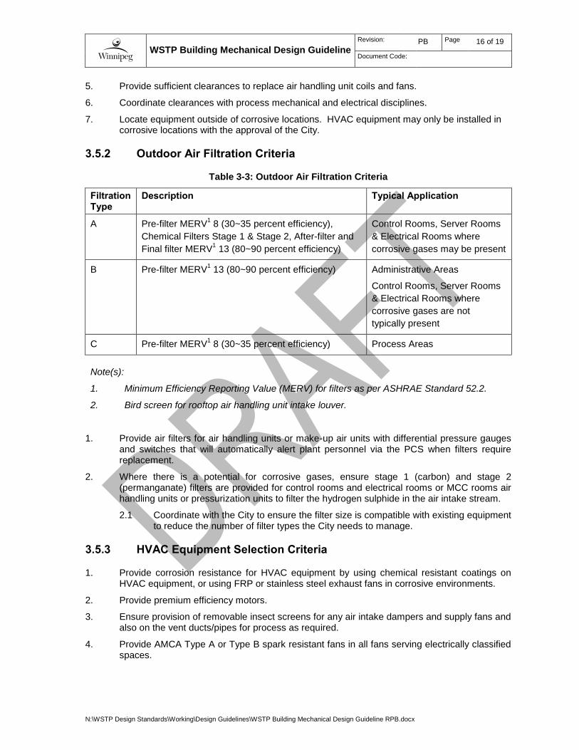
3.5.2 Outdoor Air Filtration Criteria
Table 3-3: Outdoor Air Filtration Criteria
Filtration Type
Description Typical Application
A Pre-filter MERV1 8 (30~35 percent efficiency),
Chemical Filters Stage 1 & Stage 2, After-filter and
Final filter MERV1 13 (80~90 percent efficiency)
Control Rooms, Server Rooms
& Electrical Rooms where
corrosive gases may be present
B Pre-filter MERV1 13 (80~90 percent efficiency) Administrative Areas
Control Rooms, Server Rooms
& Electrical Rooms where
corrosive gases are not
typically present
C Pre-filter MERV1 8 (30~35 percent efficiency) Process Areas
Note(s):
1. Minimum Efficiency Reporting Value (MERV) for filters as per ASHRAE Standard 52.2.
2. Bird screen for rooftop air handling unit intake louver.
1. Provide air filters for air handling units or make-up air units with differential pressure gauges and switches that will automatically alert plant personnel via the PCS when filters require replacement.
2. Where there is a potential for corrosive gases, ensure stage 1 (carbon) and stage 2 (permanganate) filters are provided for control rooms and electrical rooms or MCC rooms air handling units or pressurization units to filter the hydrogen sulphide in the air intake stream.
2.1 Coordinate with the City to ensure the filter size is compatible with existing equipment to reduce the number of filter types the City needs to manage.
3.5.3 HVAC Equipment Selection Criteria
1. Provide corrosion resistance for HVAC equipment by using chemical resistant coatings on HVAC equipment, or using FRP or stainless steel exhaust fans in corrosive environments.
2. Provide premium efficiency motors.
3. Ensure provision of removable insect screens for any air intake dampers and supply fans and also on the vent ducts/pipes for process as required.
4. Provide AMCA Type A or Type B spark resistant fans in all fans serving electrically classified spaces.

WSTP Building Mechanical Design Guideline
Revision: PB Page 17 of 19
Document Code:
N:\WSTP Design Standards\Working\Design Guidelines\WSTP Building Mechanical Design Guideline RPB.docx
3.5.4 Ductwork
1. Provide ductwork as per the below criteria:
Location High
Humidity
Corrosive Gases or Chemicals
Material Notes
Process Areas
No No Aluminium
Yes No Aluminium
Yes Mild H2S Aluminium
Yes Yes FRP
Stainless Steel
Potential for corrosion. Select appropriate corrosion resistant material.
Non-process areas.
No No Aluminum or
Galvanized steel
2. Large ductwork specifications shall be written such that Sheet Metal and Air Conditioning Contractors National Association (SMACNA) standards for duct construction are adhered to. This standard stipulates duct thickness based on size and pressure ratings.
3. Utilize round ductwork wherever possible. Where rectangular ductwork is required, limit aspect ratios to a maximum of 4:1.
4. Ensure that the maximum duct pressure drop is 25 Pascal per 30 metres of duct.
5. Provide access doors where required for inspection and maintenance, including but not limited to control dampers and fire dampers.
3.6 HVAC System Monitoring and Controls
3.6.1 HVAC Controls
1. All HVAC control and monitoring shall be by PLC, consistent with the WSTP Automation Design Guide. No exceptions shall be permitted except for the following:
1.1 Natural gas fired air handlers may utilize proprietary packaged controls for the natural gas burner and associated devices. However, the proprietary packaged controls shall not monitor or control any equipment or instrumentation outside of the air handler unit. Any liquid coils in the air handler shall be controlled by the PLC.
1.2 Boilers and chillers may utilize packaged controls that do not fully comply with the WSTP Automation Design Guide. Ensure sufficient integration into the plant PCS to meet operational requirements.
1.3 Small out-buildings with a ventilation rate of 100 l/s or less may utilize non-PLC based controls, provided the control is very basic. For example, a single unit heater may be controlled by a wall-mounted thermostat.
2. All HVAC systems shall be monitored by the plant PCS.
3. Provide room temperature sensors for control and monitoring. Provide low and high temperature alarms to operations personnel via the PCS.
WSTP Building Mechanical Design Guideline
Revision: PB Page 18 of 19
Document Code:
N:\WSTP Design Standards\Working\Design Guidelines\WSTP Building Mechanical Design Guideline RPB.docx
4. Unit heater control (including all mounted baseboard heaters, convectors, etc.):
4.1 Ensure all heater control is integrated into the overall PLC based control system. Ensure that simultaneous heating and cooling of the space is prevented.
4.2 Where there is a risk of building freezing due to the PLC being out of service, provide backup thermostats to override the PLC control upon low temperature.
5. Provide duct smoke detectors only where required by the National Building Code or local code requirements.
6. Install freeze stats for hydronic heating coils and glycol heat recovery coils of air handling units or make-up air units.
6.1 Ensure provision of a freezing alarm to the plant PCS.
7. Provide normal (low) ventilation and emergency (high) ventilation for air handling units, make-up air units or supply/exhaust fans designed for chemical areas.
7.1 High speed ventilation shall be triggered by a local push button manually outside of the entrance of chemical areas to activate the emergency exhaust fans and supply fans,
3.6.2 Gas Detection
1. General Requirements
1.1 Provide gas detection systems to monitor all potential hazardous gases.
1.2 A sufficient quantity of gas detection systems shall be provided to adequately cover the space. Do not assume that a single gas detection sensor is sufficient to cover an entire room or space.
1.3 Ensure gas detection systems are located appropriately to detect hazardous gases within the coverage area. Review ventilation flow patterns and locate the sensors appropriately. For example, it is not appropriate to locate a gas detection sensor adjacent to a supply air grille.
1.4 Locate gas detection systems at the appropriate elevation, considering the hazardous gas density, ventilation patterns, and location of personnel.
1.5 Where a dual-rate ventilation system is provided, interlock the gas detection with the ventilation system to ensure that a high-rate of ventilation is provided upon detection of a hazardous gas.
1.6 Ensure provision of detected gas levels to plant PCS. The only exception is that carbon monoxide sensors may simply transmit an alarm to the plant PCS.
2. Provide H2S sensors for process areas with a risk of hydrogen sulphide.
2.1 When the hydrogen sulphide level in the associated space exceeds the pre-set monitoring level, as per the City of Winnipeg’s WWD Hydrogen Sulphide Monitoring Program criteria, the ventilation system shall remain at a high-flow rate to provide required air changes for classified areas per NFPA 820.
3. Provide a Combustible Gas Detection system for process areas as required by NFPA 820 and interlock with space ventilation or odour control make-up air system when gas levels exceed 10 percent of the lower explosive limit as per NFPA 820.
4. Provide Carbon Monoxide (CO) sensors for direct gas-fired air handling units or make-up air units to monitor incomplete combustion of the natural gas. When CO levels of the unit discharge air is higher than the pre-set point, ensure that the unit gas burner automatically shuts down.
5. Provide Oxygen Deficiency sensors in spaces where there is a risk of oxygen displacement.
WSTP Building Mechanical Design Guideline
Revision: PB Page 19 of 19
Document Code:
N:\WSTP Design Standards\Working\Design Guidelines\WSTP Building Mechanical Design Guideline RPB.docx
6. Provide other gas detection systems as appropriate for the gases that may be present.
WSTP Building Mechanical Design Guideline
Revision: PB Page 20 of 19
Document Code:
N:\WSTP Design Standards\Working\Design Guidelines\WSTP Building Mechanical Design Guideline RPB.docx
4 PLUMBING SYSTEMS
4.1 Plumbing System Concepts
1. Ensure NPC design standards with the Manitoba plumbing code amendment are complied with for sanitary drainage, storm drain, potable water, and plant service water system design. The Canadian gas code shall be complied with for natural gas piping system design.
2. Provide potable water for washroom/janitor room’s plumbing fixtures and combination shower/eyewash stations.
3. For interior hose valves in process area, provide 25mm or 40 mm globe valves with hose thread adapters.
4. For potable hot water, the City’s preference is to utilize electric hot water heaters.
5. Design all sanitary drains and wash down gutter/floor drains to be collected in sanitary sumps in the basement.
5.1 Provide sump pump systems to pump the sanitary drainage to the discharge location.
5.2 Ensure provision of high sump level alarms to be sent to plant PCS.
5.3 Ensure the sump pumps are discharged into an appropriate location in the plant. City approval is required for all discharge locations other than the headworks.
6. Provide gutter drains for basement tunnels, pipe galleries, perimeter walls as required to collect floor wash down drain and underground seepage water.
7. Provide floor drains for process areas, mechanical rooms, washrooms, janitor rooms, locker rooms as required.
7.1 Coordinate with structural to ensure that floors are be sloped to the drains.
8. Provide hub drains for mechanical equipment including air conditioning units to collect overflow drain and condensate drain as required.
9. All floor/gutter drains and hub drains that are infrequently used shall have primed P-traps.
10. Water source for trap priming shall be either non-potable water (preferred) or flushing water.
11. Provide ganged traps where allowed by codes, otherwise provide individual traps for floor drains/gutter drains and hub drains.
12. Provide conventional roof drains and overflow drains for all new buildings. Design individual rain water leaders to discharge to grade or to be collected and discharged into the plant storm drainage system if available.
13. Drainage system piping and appurtenance material section shall be appropriate for the location to ensure corrosion resistance.
14. Provide a proximity switch for the safety shower/eyewash.
14.1 An alarm signal shall be sent to the plant PCS to notify staff in the control room that the equipment is being used.
14.2 Insulate and heat trace piping in the outdoor emergency showers to prevent piping freezing.
15. Provide natural gas piping and regulators to each natural gas fired air handling unit as required.
WSTP Building Mechanical Design Guideline
Revision: PB Page 21 of 19
Document Code:
N:\WSTP Design Standards\Working\Design Guidelines\WSTP Building Mechanical Design Guideline RPB.docx
15.1 Install natural gas piping either underground (buried) or, if possible, on building roof. Installation of natural gas piping within the basement galleries will not be accepted without approval of the City.
15.2 The natural gas meter and gas regulator at the plant gas main shall be coordinated with Manitoba Hydro for new gas loads.
4.2 Insulated Plumbing Piping
1. Provide insulation for the following pipes:
Cold potable water
Hot Potable Water and Recirculation
Plant Service Water (non-potable water)
Refrigerant and Gas Piping
Pump Seal Water
Roof/Overflow Drain Pipes
4.3 Plumbing Fixtures
1. In buildings designed in accordance with building code requirements for accessibility for persons with disabilities, provide water closets and lavatories in the washroom with barrier-free plumbing fixtures for the physically disabled.
1.1 As per the WSTP Architectural Design Guideline, only buildings having administration functionality will be designed in accordance with building code requirements for accessibility for persons with disabilities.
2. Water closets shall be wall-mounted or floor-mounted, flush-valve-type complete with dual-flow control.
3. Provide mop sinks for janitor room.
4. Provide wall-hung, flush-valve-type urinals for washroom as required.
4.4 Emergency Safety Equipment
1. Provide emergency eyewash and shower stations with control mixing valves for tempered water for process areas and chemical areas wherever required for safety protection.
2. Ensure that the safety mixing valve is pre-set to 26.7 deg. Celsius (80 deg. Fahrenheit) by the manufacturer for the mixing temperature of cold and hot water supply.
4.5 Water Conservation
1. Specify and install low water consumption plumbing fixtures and trim in accordance with the requirements of the Manitoba Building Code.
2. Provide high-efficiency plumbing fixtures for water use reduction.
3. Provide water meters for main water usage facility as per City Standards
WSTP Building Mechanical Design Guideline
Revision: PB Page 22 of 19
Document Code:
N:\WSTP Design Standards\Working\Design Guidelines\WSTP Building Mechanical Design Guideline RPB.docx
4.6 Cross-Connection Control
1. Provide cross-connection control in accordance with the CSA standards.
2. Install backflow prevention assemblies for the following: potable cold water main entrances into each new building with a double check valve back-flow prevention assembly and non-potable water main entrance into each new building with a reduced pressure backflow prevention assembly.
3. Provide local reduced pressure backflow preventers for the HVAC heating system and glycol heat recovery system make-up water as required.
4.7 Plumbing Equipment
1. Include plumbing equipment for sump pumps and hot water heaters.
2. Building sanitary drains for plumbing system shall be discharged by gravity drain to available plant main sanitary systems.
2.1 Where gravity drain is not possible, duplex sanitary sump pumps shall be provided in the basement of process areas and pipe galleries to collect sanitary drainage from washrooms, floor/gutter drains and seepage drains, and the drainage flow shall be pumped and discharged into the plant head works via basement tunnels.
2.2 Provide sump pits for the basement tunnel as required.
3. Provide gas or electric domestic hot water heaters/tanks for potable hot water to washrooms/janitor rooms and to emergency shower/eyewash station mixing valves.
3.1 Install small hot water recirculation pumps to compensate for hot water piping heat loss for remote plumbing fixtures and safety shower/eyewash station as required.
WSTP Building Mechanical Design Guideline
Revision: PB Page 23 of 19
Document Code:
N:\WSTP Design Standards\Working\Design Guidelines\WSTP Building Mechanical Design Guideline RPB.docx
5 FIRE PROTECTION SYSTEMS
1. Co-ordinate with the architect for the design of sprinkler systems and standpipe system for locations of required fire pump and fire protection water supply.
2. Determine if fire pump is required to boost the fire protection water pressure to meet the required pressure for sprinkler system or standpipe system.
3. Prepare the detail design and installation of sprinkler system and standpipe system and ensure that it is certified by a Fire Protection Engineer.
4. Provide portable fire extinguishers as required and coordinate with the architectural drawings. All fire extinguishers shall be identified as per the City WWD Identification Standard.
5. Ensure provision of fire dampers on the ductwork penetrating any fire-rated walls, and floor slabs as required per codes.
6. Where duct smoke detectors are required, ensure smoke detector alarm contact is connected to the fire alarm panel.

WSTP Building Mechanical Design Guideline
Revision: PB Page 24 of 19
Document Code:
N:\WSTP Design Standards\Working\Design Guidelines\WSTP Building Mechanical Design Guideline RPB.docx
6 BUILDING MECHANICAL DESIGN TEAM RESPONSIBILITIES
6.1 General
1. Responsibility for deliverables
1.1 All drawings and other deliverables related to a design are the responsibility of the design engineer. Under a Design-Bid-Build project delivery methodology, delegation of design responsibility to the contractor is not acceptable.
2. Ensure all building mechanical deliverables are sealed by a qualified professional engineer.
3. Completeness of drawings:
3.1 All drawings shall be comprehensive in nature to allow for effective use in construction.
4. Update of existing drawings:
4.1 If the project is an addition, expansion, upgrade or modification to an existing site or facility, existing drawings may require up-dating. Coordinate with the City to understand the specific requirements. Typical requirements include.
Updating existing building floor plans.
Updating P&ID drawings.
The update of detail drawings for existing works is not expected or required.
5. As-Built Drawings:
5.1 All building mechanical deliverables shall be updated to “as-built” status at the end of the project. The “as-built” documents shall incorporate contractor mark-ups, inspections performed by the design team, change orders, RFIs, and other communication between the Contractor and Design Team.
5.2 Unless otherwise specified by the City and agreed to by the Design Team, as-built drawings are not required to be sealed (Otherwise known as record drawings).
6. External, 3rd
Party Consultants:
6.1 Expertise and assistance may be required, from external 3rd
party specialized consultants, outside of the primary architectural / design team.
6.2 Areas where an external 3rd
party consultant may be utilized, with permission from the City, are:
Fire protection systems.
Acoustic systems.
6.3 The design team shall be responsible for monitoring the activities and progress of each 3
rd party consultant.
6.4 It is the responsibility of the design engineer to ensure that the deliverables follow all City standards and guidelines.
7. Site Visits:
7.1 The design team is responsible for ensuring that a sufficient number of site visits occur to facilitate the understanding of specific field conditions or status of existing facilities and buildings.
WSTP Building Mechanical Design Guideline
Revision: PB Page 25 of 19
Document Code:
N:\WSTP Design Standards\Working\Design Guidelines\WSTP Building Mechanical Design Guideline RPB.docx
8. Demolition Requirements
8.1 It is generally required that the architect / engineer is responsible for associated demolition works required to implement the scope of work. Clearly indicate all demolition requirements on the drawings and in the specifications.
8.2 Small demolition works shall generally be shown by revision of existing drawings. Where demolition requirements are significant, create dedicated demolition drawings.
6.2 Drawings
The drawings indicated in this section are minimum requirements for new construction, unless otherwise approved by the City.
6.2.1 Legend
1. Requirement
1.1 Provide a legend drawing showing the symbols and abbreviations utilized. Coordinate with the City regarding re-use of any existing legend drawings.
2. Content
2.1 Ensure that the legend is consistent with the City’s practices. Symbols shall be the same as process mechanical symbols for common items (i.e. valves).
3. Format:
3.1 Produce drawings in an A1 size format.
6.2.2 Process and Instrumentation Diagrams
1. Requirement
1.1 Provide P&ID’s for the complete HVAC system, including all hydronic systems, unit heaters and associated controls.
1.2 Provide P&IDs for the complete plumbing system. All components shall be shown on the P&IDs except for floor drainage systems.
2. Content
2.1 P&ID’s shall depict all equipment and ductwork, including AHUs, fans, cooling coils, heating coils, filters, dampers, etc.
2.2 All automation and control components including instrumentation such as pressure gauges, temperature sensors, RH sensors and manometers shall also be indicated.
3. Format
3.1 Produce drawings in an A1 size format.
3.2 The P&IDs shall be in the same format as the process P&IDs.
3.3 The P&IDs shall be in a format compliant with the City WWD Identification Standard and ISA 5.1.
WSTP Building Mechanical Design Guideline
Revision: PB Page 26 of 19
Document Code:
N:\WSTP Design Standards\Working\Design Guidelines\WSTP Building Mechanical Design Guideline RPB.docx
6.2.3 Schematic Airflow Diagram
1. Requirement:
1.1 Provide a schematic airflow diagram for the complete HVAC system.
2. Content:
2.1 Show all ventilated spaces and flow of air through each space.
2.2 Show all airflow rates.
2.3 Show room pressurization.
2.4 Show all fans and air handling units.
3. Format:
3.1 Produce drawings in an A1 size format.
6.2.4 Building Mechanical Plan Drawings
1. Requirement
1.1 Building mechanical plan drawings are required for every floor elevation, including the roof.
2. Content:
2.1 Show the arrangement of all HVAC equipment, including ductwork and piping.
2.2 Show all AHU’s, condensing units, volume control dampers, fire dampers, grilles, registers, unit heaters, ventilation fans and all other accessories.
2.3 Show duct sizes and duct elevations.
2.4 Provide a scale bar to allow for scale takeoffs.
3. Format:
3.1 Produce drawings in an A1 size format.
3.2 Scale:
3.2.1 Recommended: 1:75
3.2.2 Maximum: 1:100
6.2.5 Building Mechanical Section and Detail Drawings
1. Requirement
1.1 Provide building mechanical section and detail drawings to completely make clear the required installation of the mechanical systems.
2. Content
2.1 Ensure all materials of construction and dimensions are clearly identified.
3. Format:
3.1 Produce drawings in an A1 size format.
3.2 Scale:
3.2.1 Recommended: 1:50
3.2.2 Maximum: 1:100
WSTP Building Mechanical Design Guideline
Revision: PB Page 27 of 19
Document Code:
N:\WSTP Design Standards\Working\Design Guidelines\WSTP Building Mechanical Design Guideline RPB.docx
6.2.6 Schedule Drawings
1. Requirements
1.1 Provide schedule drawings for all building mechanical equipment.
2. Content
2.1 The content of the schedule drawings shall include but not be limited to:
2.1.1 AHU schedules
2.1.2 Fan schedules
2.1.3 Grille/louvre/diffuser schedules
2.1.4 Unit heater schedules
2.1.5 Heat exchanger schedules
2.1.6 Pump schedules
2.1.7 Expansion tank schedules
2.1.8 Heater schedules
2.1.9 Air conditioning unit schedules
2.1.10 Condensing unit schedules.
2.1.11 Damper schedules.
3. Format:
3.1 Produce drawings in an A1 size format.
6.2.7 Pipe Work Layout Drawings
1. Provide drawings clearly showing piping layouts and associated pipe accessories.
2. Provide isometrics for piping.
3. Include pipe schedules and sizes.
6.2.8 Fire Fighting Layout Drawings
1. Provide drawings showing the firefighting equipment and piping layouts.
2. Provide fire extinguisher, fire hose reel and hydrant schedules.
6.2.9 Installation Detail Drawings
1. Requirements
1.1 Provide piping detail drawings.
1.2 Provide plumbing detail drawings.
1.3 Provide HVAC detail drawings.
1.4 Existing City piping detail drawings may be referenced if available and appropriate for the project.
2. Content
2.1 Content requirements include, but are not limited to:
2.1.1 Typical duct support requirements for all duct configurations.
2.1.2 Duct connection details, including odour control connections to tanks and channels.
WSTP Building Mechanical Design Guideline
Revision: PB Page 28 of 19
Document Code:
N:\WSTP Design Standards\Working\Design Guidelines\WSTP Building Mechanical Design Guideline RPB.docx
2.1.3 Duct insulation details.
2.1.4 Fan installation details (i.e. roof mounted fan)
2.1.5 Typical pipe supports for all piping configurations.
2.1.6 Piping floor/wall/roof penetration installation details.
2.1.7 Duct floor/wall/roof penetration installation details.
2.1.8 Piping flushing connection details.
2.1.9 Instrumentation installation details.
2.1.10 Pipe marking details.
2.1.11 Hose rack and other appurtenances details.
2.1.12 Pipe insulation details.
3. Format:
3.1 Produce drawings in an A1 size format.
6.2.10 3D Model
1. When 3D design is required by the City, or proposed by the Consultant, this section shall be complied with in its entirety. 3D models and associated drawings are not mandatory for all projects
2. The 3D model shall include all pipework, ductwork and equipment to allow for full representation of the entire facility, including all other disciplines.
3. In addition to the 3D model provide:
3.1 3D elevation and section drawings to convey the complete building mechanical configuration.
3.2 3D detail drawings of all areas with significant interdisciplinary coordination requirements.
4. 3D drawings shall be rendered. Simple 3D line representations are not acceptable.
6.2.11 Coordination with Other Disciplines
1. Structural / Architectural
1.1 Ensure that openings for ductwork, louvres, and other openings are coordinated with, and shown on the structural and architectural drawings.
1.2 Ensure all equipment weights are coordinated with the structural design.
1.3 Where new equipment is installed on an existing floor/roof, the engineer is responsible for coordinating the appropriate structural review to ensure that the weight of the equipment is supported. Upgrade the existing structure as required.
1.4 Where new penetrations are made to an existing structure, ensure that structural elements are not affected. Coordinate the appropriate structural review and upgrade as required.
1.4.1 Where penetrations are made through reinforced concrete, care should be taken during the design planning and construction stages to minimize the cutting of reinforcement.
WSTP Building Mechanical Design Guideline
Revision: PB Page 29 of 19
Document Code:
N:\WSTP Design Standards\Working\Design Guidelines\WSTP Building Mechanical Design Guideline RPB.docx
6.3 Design Calculations
1. As a minimum, provide the following non-exhaustive list of HVAC and building mechanical design data and calculations:
Tabulation of interior heat loads (heat dissipation).
Calculation of heating load.
Calculation of the cooling load.
Calculation of air flow rates.
Calculation of make-up air flow rates for the building pressurization.
Calculation of static duct pressure drops.
Sizing of ducts, grilles, registers, diffusers, valves, dampers, louvers, filters, cooling coils, air heaters, fans, compressors, condensers, refrigerant and drain pipes.
Plumbing and firefighting piping and equipment design calculations.