electric vehicle charging infrastructure installation...
TRANSCRIPT


Electric Vehicle Charging Infrastructure Installation Guide
Twin Charge 13/32 and 32/32 Models
PP_2111PP_2151PP_2152

POD Point Twin charge is the next generation in electric vehicle charging for local councils and corporate clients looking to join the electric vehicle revolution. Inexpensive and simple to install, it minimises the increase in street furniture and ofers a level of management and control not seen before through the POD Point Communication Network.
Each POD Point can charge two vehicles simultaneously, which signifcantly reduces the efective cost per charging socket.
All POD Points use industry-standard foundations and electrical connections – making them extremely easy to install and connect using existing contractors with minimal additional training.
This document gives an outline of what is required for installing a POD Point from a civil and electrical perspective.
Introduction
Installation Guide
Section 0: Before you begin 2Section 1: Contents of Box 3 Section 2: Civil Work 5 Section 3: Electrical Work 6Section 3.1: Dedicated supply direct onto main 7 Section 3.2: Extension to existing supply 8
Section 4: Final connect up & commissioning the Installation 9Appendix A: Commissioning Handover Certifcate 10Appendix B: Troubleshooting 11Appendix C: Signage, Bay markings and guards 12
Contents
PP_2111PP_2151PP_2152
Pg.1 Version 2.2 2012 POD Point Limited w: www.pod-point.com t: 0207 247 4114 e: [email protected]

Pod Points are designed to give a long and reliable service life. However, the operational reliability depends on a number of installation factors. Before starting installation, please confrm the following: ?? There is a good GSM (Orange) signal available at the installation site;?? A suitable power source is within reasonable distance of the proposed location (consult a qualifed electrician if
required); ?? The proposed site has been selected in order to minimise the risk of damage to the POD Point.
Note on GSM signalPOD Points communicate with a control network via a GSM/GPRS connection. To allow this, a 2G mobile phone signal is required and must be checked at the site survey.
Signal measurement is not an exact science as every mobile device/antenna receieves with a diferent gain, but as a general guide; if the signal is:
> 80dBm: Reception should be good- 90 dBm to 81dBm: Communication maybe slow sometimes- 99dBm to 91dBm: Communication is unlikely to be established. Note: the POD Point can still operate in standalone mode, but usage data and remote support will not be available.
If any of the above requirements are not satisfed, please consult POD Point on 0207 247 4114. Alternative GSM network confgurations are available if required.
Section 0 : Before you Begin
Version 2.2 2012 POD Point Limited w: www.pod-point.com t: 0207 247 4114 e: [email protected] Pg. 2

Section 1 : Contents of Box
MechanicalDepending on model, your POD Point may be shipped in a complete unit, or as three modules:
Module 1: Charging head (containing charging sockets and control circuitry) Module 2: Power post (containing the electrical distribution and safety equipment) Module 3: Foundation adapter (surface, subterranean or NAL)
Where units are shipped as modules, the assembly screws are included with Module 2 (power post), supply fuses are shipped with Module 1 (power head).
Module 1POD PointCharging head
POD PointFoundation
Module 2POD PointPower post
4x M6 security screws (10Nm)
4x M10 security screws (40Nm)
Surafce Mountfoundation adaptor
Subterraneanfoundation adaptor
NALfoundation adaptor
Module 3
Pg.3 Version 2.2 2012 POD Point Limited w: www.pod-point.com t: 0207 247 4114 e: [email protected]
Other items not supplied, but that may be required:
?? M10 or M12 x 120 mm (minimum) countersunk security anchor bolts x 4 (surface mount only, suitable for local substrate)
?? 5 mm steel rod (for stabilising subterranean foundation during installation only) ?? RS115 NAL socket (NAL adapter only)?? Feeder Piller
Section 1.2: Assembly/Installation Tools
Tools required:Torque wrench (min. 8 – 30 Nm) Bit adapter Security Torx BitsDrill and masonry bit to suit anchor bolts (surface mount and guards only)Hammer (surface mount only)Spanner or socket (surface mount only)Spirit level
Assembly Procedure summary
1. Installation foundation, foundation adapter and power supply (see sections 2 and 3) 2. Install power post onto foundation adapter 3. Insert 3 x M10 securing screws and tighten to 30 Nm 4. Remove red cover from power distribution box 5. Connect power supply 6. Replace red cover on power distribution box 7. Insert fuse(s) (supplied with the power head) and afx the appropriate rating label to the fuse holders. Note for 13/32
models (PP_2111) the 16A fuse MUST be installed in the right hand fuseholder. 8. Install power head
8.1 Insert the power head onto the post (make sure that the face of the head is pointing the right way, that the internal brackets align with the slots in the post and that the rubber seal is correctly located over the post)8.2 Connect power plugs (1x4 way and 1 x3 way)8.3 Connect 1 x 8-way control plug 8.4 Check all connectors for dislodged pins and security 8.5 Install 3 x M6 security screws and tighten to 8 Nm (roll up the seal to access fxing holes)
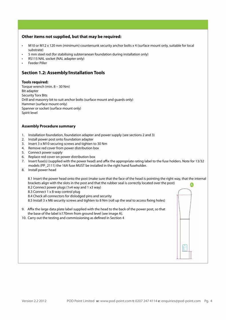
9. Afx the large data plate label supplied with the head to the back of the power post, so that ........the base of the label is170mm from ground level (see image A). 10. Carry out the testing and commissioning as defned in Section 4
A
Version 2.2 2012 POD Point Limited w: www.pod-point.com t: 0207 247 4114 e: [email protected] Pg. 4
Section 2.1: Surface Mount
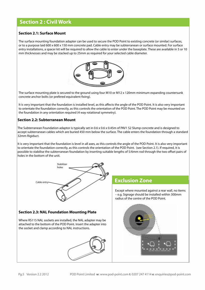
The surface mounting foundation adapter can be used to secure the POD Point to existing concrete (or similar) surfaces, or to a purpose laid 600 x 600 x 150 mm concrete pad. Cable entry may be subterranean or surface mounted. For surface entry installations, a spacer kit will be required to allow the cable to enter under the baseplate. These are available in 5 or 10 mm thicknesses and may be stacked up to 25mm as required for your selected cable diameter.
The surface mounting plate is secured to the ground using four M10 or M12 x 120mm minimum expanding countersunk concrete anchor bolts (or prefered equivalent fxing).
It is very important that the foundation is installed level, as this afects the angle of the POD Point. It is also very important to orientate the foundation correctly, as this controls the orientation of the POD Point. The POD Point may be mounted on the foundation in any orientation required (4 way rotational symmetry).
Section 2 : Civil Work
Section 2.2: Subterranean Mount
The Subterranean Foundation adaptor is typically set in 0.6 x 0.6 x 0.45m of PAV1 S2 Slump concrete and is designed to accept subterranean cables which are buried 450 mm below the surface. The cable enters the foundation through a standard 32mm Rigiduct.
It is very important that the foundation is level in all axes, as this controls the angle of the POD Point. It is also very important to orientate the foundation correctly, as this controls the orientation of the POD Point. (see Section 2.1). If required, it is possible to stabilise the subterranean foundation by inserting suitable lengths of 5/6mm rod through the two ofset pairs of holes in the bottom of the unit.
Section 2.3: NAL Foundation Mounting Plate
Where RS115 NAL sockets are installed, the NAL adapter may be attached to the bottom of the POD Point. Insert the adapter into the socket and clamp according to NAL instructions.
Except where mounted against a rear wall, no items – e.g. Signage should be installed within 300mm radius of the centre of the POD Point.
Exclusion ZoneCable entry
Stabilizer holes
Pg.5 Version 2.2 2012 POD Point Limited w: www.pod-point.com t: 0207 247 4114 e: [email protected]

Each POD Point ideally needs a 240V single phase connection capable of continuously supplying >64 A. This will allow for easy upgrading for faster charging options in the future. Where such a supply is not possible, PP_2111 will accept a 45A supply, or POD Point can confgure a power management feature to reduce total load to 32A if required (please contact POD Point to discuss this). Each POD Point also needs a separate earth (not connected to neutral) usually supplied by an Earth spike or mat (TT system), which is fed into the POD Point via a separate conductor. The earth should have a maximum resistance of 20 ohms.
There are typically two types of cable installation:
?? Dedicated supply direct onto main, grid.?? Extension to existing supply.
Connection
2 standard BN25 SWA cable glands are provided to allow cable termination at the charging point. Models ftted with a 4-way switch disconnector may be supplied from either a 240VAC single phase or a 415VAC 3-phase supply.
Units are supplied with a jumper between L1 and L2 on the supply side to allow connection to a single phase supply. This should be removed if installing a 3-phase supply. If both sockets are to be fed from the same phase, then the power conductors on the load side should be moved from L1 and L2 to a common phase as required.
The incoming terminals will accomodate rigid conductors up to 55mm2 or fexible conductors up to 35mm2
All electrical installations must be carried out by a qualifed electrician an be in compliance with BS 7671.
Section 3 : Electrical Work
Version 2.2 2012 POD Point Limited w: www.pod-point.com t: 0207 247 4114 e: [email protected] Pg. 6
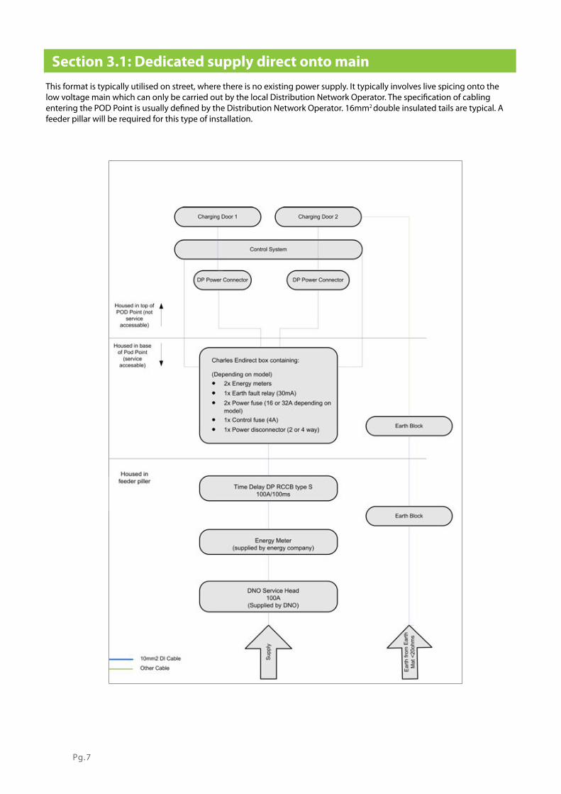
This format is typically utilised on street, where there is no existing power supply. It typically involves live spicing onto the low voltage main which can only be carried out by the local Distribution Network Operator. The specifcation of cabling entering the POD Point is usually defned by the Distribution Network Operator. 16mm2 double insulated tails are typical. A feeder pillar will be required for this type of installation.
Section 3.1: Dedicated supply direct onto main
Pg.7
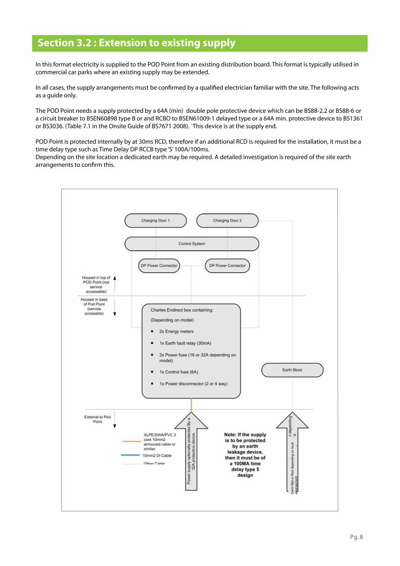
In this format electricity is supplied to the POD Point from an existing distribution board. This format is typically utilised in commercial car parks where an existing supply may be extended.
In all cases, the supply arrangements must be confrmed by a qualifed electrician familiar with the site. The following acts as a guide only.
The POD Point needs a supply protected by a 64A (min) double pole protective device which can be BS88-2.2 or BS88-6 or a circuit breaker to BSEN60898 type B or and RCBO to BSEN61009-1 delayed type or a 64A min. protective device to BS1361 or BS3036. (Table 7.1 in the Onsite Guide of BS7671 2008). `This device is at the supply end.
POD Point is protected internally by at 30ms RCD, therefore if an additional RCD is required for the installation, it must be a time delay type such as Time Delay DP RCCB type ‘S’ 100A/100ms.Depending on the site location a dedicated earth may be required. A detailed investigation is required of the site earth arrangements to confrm this.
Section 3.2 : Extension to existing supply
Earth
Mat
or R
od d
epen
ding
on
loca
l ar
rang
emen
t
Pg.8

Once the Civil and Electrical work has been completed (see sections 2 and 3), and the POD Point ftted, the installation requires testing.
To meet BS7671 (17th edition) requirements for testing of an electrical installation, the following shall be performed by an accredited electrician1:
?? ??????????????????? ????????????????????????????????????????????????????????????? ??????????????????????????????????????? ????????????????????????? ???????????????????????????? ?????????? ???????????????????????????? ????????????????????????????????? ??????????????????????????????????????? ?????????????????????????
The main power supply to the POD Point should now be switched on.
Once the main supply has been switched on, the POD Point will take approximately 1 minute to “boot up”, and perform a diagnostic self check.
After this is complete, the LCD will show the POD Point Logo and the message “Please swipe your tag to begin” and the blue LED strip lights down the left and right of the body will illuminate.
The installer should complete the commissioning form (Appendix A or Quickstart Guide) with the relevant information, before calling the POD Point remote commissioning team on 0207 2474114 to register the installation.
____________________________________________________________________________________________________
1 Electricians must be accredited by a recognized body such as:
BRE Certifcation LtdBritish Standards InstituteELECSA LtdNAPIT Certifcation LtdNICEIC Group Ltd
Section 4: Final connect up & commissioning the Installation
Pg.9 Version 2.2 2012 POD Point Limited w: www.pod-point.com t: 0207 247 4114 e: [email protected]

Appendix A: Commissioning Handover Certifcate
POD Point EV charging equipment will provide basic functionality on frst installation, however each point must be registered and commissioned onto the POD Point network to enable full functionality and remote support. The data below should be completed for each installation and returned to [email protected]. Where a latitude and longitiude are not available, please supply a detailed description and photograph of the charging point location.
This certifcate may be completed by hand and scanned to email, or please contact the above email address to re-quest a soft copy of the certifcate in Word.
Please complete Sections 1, 2, 3 and 4. POD Point will complete Sections 5 and 6, to fnalise activation. The completed certifcate may be returned for the post owner, on request.
1. POD Location Details to be Completed
POD Location name
POD Location address
Postcode
Latitude
Longitude
2. POD Owner Details to be Completed
Owner / Customer
Owner address
Owner postcode
Postcode
Contact name
Contact number
3. Commissioning Details to be Completed
Date
PPID
Source of electricity (ref no/description)
Confrm power switched on
Confrm functional test complete
Communications test complete: phone POD Point on 020 7247 4114
Electrical Safety Test Certifcate No. BS7671 (attach copy)
Feeder pillar Key number
Key holder
Orange signal (stength dBm)
Version 2.2 2012 POD Point Limited w: www.pod-point.com t: 0207 247 4114 e: [email protected] Pg. 10

4. To be completed by the installer
On behalf of the installer, I hereby confrm that:
We have completed the installation in accordance with the Installation Manual; the POD Point has been connected to the electricity supply and commissioned;the installation has been tested for electrical safety; the above commissioning details are true and accurate.
Name:............................................................................ Position .................................................................................................................
Date:.............................................................................. Compny:…………………………………………………......................
Please send this certifcate, with Sections 1-4 completed, to [email protected].
5. Activation DetailsDate POD entered into PPMS
Date Whitelist updated
Date Confguration updated
Firmware version
Date POD activated
6. To be completed by POD Point
We hereby confrm that:
The POD Point has been installed and commissioned; The above commissioning details are true and accurate.
Name:............................................................................. Position ..............................................................................
Date:..........................................................................
Any Additional Notes
Pg.11 Version 2.2 2012 POD Point Limited w: www.pod-point.com t: 0207 247 4114 e: [email protected]
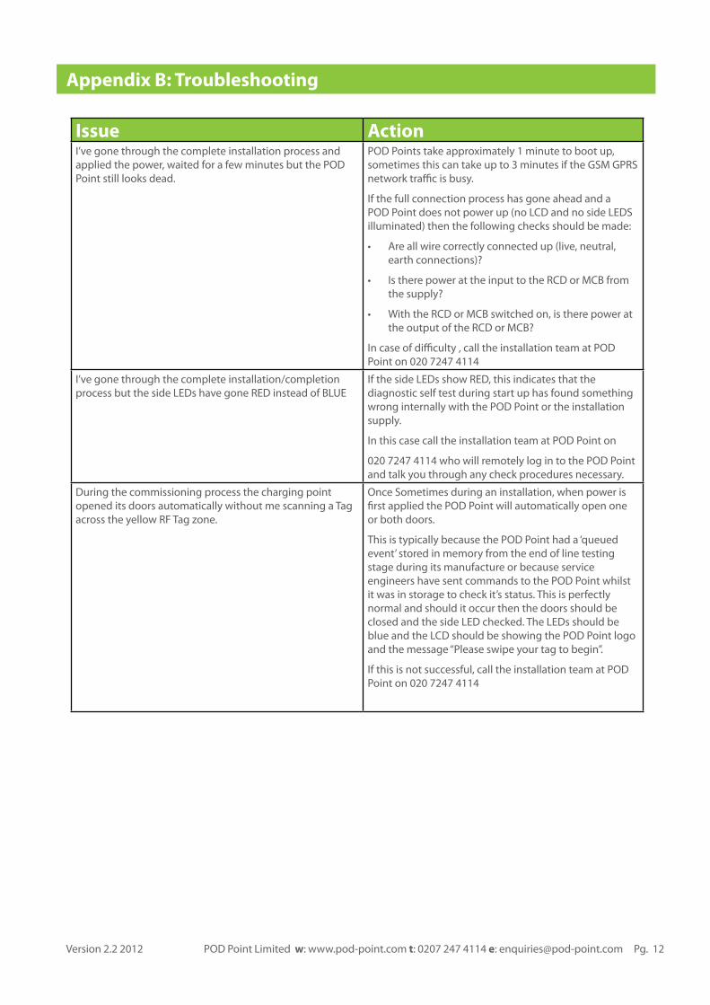
Issue ActionI’ve gone through the complete installation process and applied the power, waited for a few minutes but the POD Point still looks dead.
POD Points take approximately 1 minute to boot up, sometimes this can take up to 3 minutes if the GSM GPRS network trafc is busy.
If the full connection process has gone ahead and a POD Point does not power up (no LCD and no side LEDS illuminated) then the following checks should be made:
?? Are all wire correctly connected up (live, neutral, earth connections)?
?? Is there power at the input to the RCD or MCB from the supply?
?? With the RCD or MCB switched on, is there power at the output of the RCD or MCB?
In case of difculty , call the installation team at POD Point on 020 7247 4114
I’ve gone through the complete installation/completion process but the side LEDs have gone RED instead of BLUE
If the side LEDs show RED, this indicates that the diagnostic self test during start up has found something wrong internally with the POD Point or the installation supply.
In this case call the installation team at POD Point on
020 7247 4114 who will remotely log in to the POD Point and talk you through any check procedures necessary.
During the commissioning process the charging point opened its doors automatically without me scanning a Tag across the yellow RF Tag zone.
Once Sometimes during an installation, when power is frst applied the POD Point will automatically open one or both doors.
This is typically because the POD Point had a ‘queued event’ stored in memory from the end of line testing stage during its manufacture or because service engineers have sent commands to the POD Point whilst it was in storage to check it’s status. This is perfectly normal and should it occur then the doors should be closed and the side LED checked. The LEDs should be blue and the LCD should be showing the POD Point logo and the message “Please swipe your tag to begin”.
If this is not successful, call the installation team at POD Point on 020 7247 4114
Appendix B: Troubleshooting
Version 2.2 2012 POD Point Limited w: www.pod-point.com t: 0207 247 4114 e: [email protected] Pg. 12
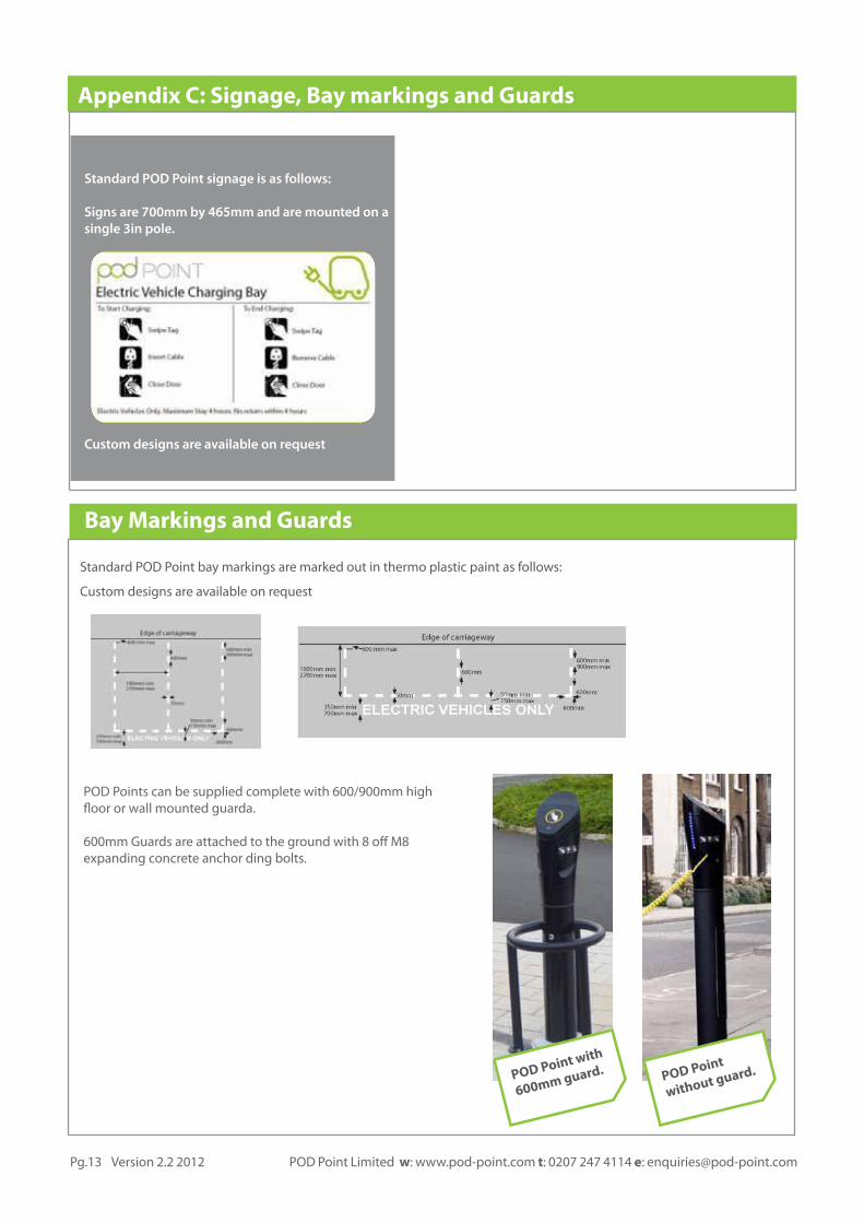
Standard POD Point signage is as follows:
Signs are 700mm by 465mm and are mounted on a single 3in pole.
Custom designs are available on request
Standard POD Point bay markings are marked out in thermo plastic paint as follows:
Custom designs are available on request
Bay Markings and Guards
POD Points can be supplied complete with 600/900mm high foor or wall mounted guarda.
600mm Guards are attached to the ground with 8 of M8 expanding concrete anchor ding bolts.
POD Point
without guard.POD Point with
600mm guard.
Appendix C: Signage, Bay markings and Guards
Pg.13 Version 2.2 2012 POD Point Limited w: www.pod-point.com t: 0207 247 4114 e: [email protected]
