electric energy challenges of the future systems engineering ... focus on electric energy challenges...
TRANSCRIPT
Electric Energy Challenges of the Future
Future Grid Thrust Area 1 White Paper
Power Systems Engineering Research Center
Empowering Minds to Engineerthe Future Electric Energy System
Thrust Area 1 White Paper
Electric Energy Challenges of the Future
Project Team
Gerald T. Heydt, Kory Hedman
Arizona State University
James D. McCalley, Dionysios Aliprantis
Iowa State University
Mani Venkatsubramanian
Washington State University
PSERC Publication 12-11
May 2012
For information about this white paper contact:
Gerald T. Heydt, Regents’ Professor
School of Electrical, Computer and Energy Engineering
Arizona State University
P.O. Box 875706
Tempe, Arizona 85287-5706
Phone: (480)-965-8307
Email: [email protected]
Power Systems Engineering Research Center
The Power Systems Engineering Research Center (PSERC) is a multi-university Center
conducting research on challenges facing the electric power industry and educating the
next generation of power engineers. More information about PSERC can be found at the
Center’s website: http://www.pserc.org.
For additional information, contact:
Power Systems Engineering Research Center
Arizona State University
527 Engineering Research Center
Tempe, Arizona 85287-5706
Phone: (480)-965-1643
Fax: (480)-965-0745
Notice Concerning Copyright Material
This copyrighted document may be distributed electronically or in print form as long as it
is done (1) with the entire document including the cover, title page, contact page,
acknowledgements, and executive summary in addition to the text, and (2) attribution is
given to the Power Systems Engineering Research Center as the sponsor of the white pa-
per.
2012 Arizona State University. All rights reserved.
i
Acknowledgements
The support for research on electric energy challenges for the future came from an initiative
funded by Office of Electricity Delivery and Energy Reliability, U.S. Department of Energy un-
der a contract entitled “The Future Grid to Enable Sustainable Energy Systems: An Initiative of
the Power Systems Engineering Research Center”.
Acknowledgement is also due to the research assistants who worked on this initiative, especially:
Kushal Dave (ASU), Venkat Krishnan (ISU), Santiago Lemos (ISU), Yifan Li (ISU), Joshua
Lyon (ASU), Brian Pierre (ASU), Ahmed Salloum (ASU), Hugo Villegas-Pico (ISU), Fengyu
Wang (ASU).
ii
Executive Summary
This is a white paper on research related to the future power grid in the United States. The objec-
tive period is through the year 2050. The central theme is the inclusion of high levels of renewa-
ble resources, principally wind and solar energy. The intent is to give an over The Horizon view
of the evolution of the transmission grid emphasizing new technologies, applications of system
theory and algorithms, and considering new infrastructures. The elements of this research area
focus on electric energy challenges of the future through four critical areas:
Transmission system design
Substantive changes in power distribution system design
Dynamic balancing of load and generation
Wide area controls, including integrative controls in the transmission and distribution
systems.
The significance of this effort in the context of the stated U. S. Department of Energy “Scientific
Discovery and Innovation” Strategic Theme #3 includes:
The assessment of advances in basic energy science to utilize selected technologies
The impact of the use of those technologies in a power engineering context
Reduction of dependence on foreign oil
The implementation of digital/computational science tools to realize a next generation
power system.
Relating to fundamental overhead and underground transmission, a wide range of eventual tech-
nologies is studied. These include ultra-high voltage (e.g., > 1000 kV): six phase transmission
and related polyphase designs: high voltage DC (including expansion of existing facilities, rout-
ing of circuits in Mexico, multi-terminal DC, and meshed DC systems); and variable frequency
concepts. The new advances in high temperature low sag overhead conductors, and compact
overhead designs appear to yield from 100% to nearly 200% improvement in transmission char-
acteristics. It is possible that the main element in future systems with high levels of renewables
shall be the study, development, and ultimate implementation of high levels of energy storage.
Transmission overlay plans are discussed for the United States. It is likely that the present trans-
mission system shall evolve into a system that uses a portfolio of technologies. Illustrations of
transmission capacity needs for a renewable-heavy generation portfolio are given.
An important feature of the future system with high levels of renewable resources is the provi-
sion of generation reserves. This is the case since many renewable resources are variable in na-
ture. A discussion is given for the calculation and alternatives for reserve requirements. Also, the
real time control of the system in the new environment is important. Accordingly, the concept of
wide area controls is applied to take advantages of new digital and communication technologies.
The challenge of wide area controls is to develop the correct mix of substation controls, voltage
stability controls, power grid controls, and their concomitant hardware and communication re-
quirements.
iii
Table of Contents
Introduction ..................................................................................................................................... 1
1. The Opportunity and the Challenge .......................................................................................... 3
1.1 Research Opportunities in Transmission Engineering ....................................................... 3
1.2 The Research Issues ........................................................................................................... 4
2. The Future Grid......................................................................................................................... 7
2.1 Fundamental Transmission Engineering Challenges ......................................................... 7
2.2 Transmission Overlay Plans ............................................................................................ 11
2.3 Robust and Dynamic Reserve Requirements ................................................................... 13
2.4 Wide Area Control ........................................................................................................... 18
3. Conclusions ............................................................................................................................. 20
References ..................................................................................................................................... 22
iv
List of Figures
Figure 1: A conceptual diagram indicating long term forecasts of technologies and the
configuration of the electric energy infrastructure ......................................................... 2
Figure 2: Research on integrating transmission and distribution engineering eventualities ......... 3
Figure 3: Stylized, simplified southern portion of the Western interconnection in North
America.. ...................................................................................................................... 10
Figure 4: Simplified schematic of a meshed HVDC network joining WECC and mainland CFE
(Mexico) ....................................................................................................................... 10
Figure 5: Illustration of transmission capacity needs for a renewable-heavy generation portfolio
...................................................................................................................................... 12
Figure 6: Multi-farm collection network ..................................................................................... 14
Figure 7: Impact due to improving reserve requirements ............................................................ 17

v
List of Tables
Table 1: Increase in current and cost for HTLS conductor compared to conventional
conductors ....................................................................................................................... 8
Table 2: Resistance of HTLS conductor compared to conventional conductors ........................... 8
1
Introduction
Electric power engineering is often viewed as a mature topic since the inception of this field
dates back nearly 100 years. However, one can identify distinct milestones in the field that have
become ‘game changers’ in the sense that these critical milestones have caused a radical change
in design and operation. As examples, the concept of networking the transmission system was at
first deemed impossible – because it was thought that synchronizing AC generation over long
distances was not feasible. However, large scale networking has become a design hallmark of
contemporary transmission systems. Another example of a transmission design milestone was
the use of digital computers to evaluate alternative designs (as well as alternative operating sce-
narios). The game changing features that face contemporary electric energy engineering include
the utilization of renewable energy resources (including both design and operation issues), and
maximizing the automated features of the system so that operation makes maximal use of the
assets available. Also, the expanded use of electric energy in the transportation sector will allevi-
ate dependence on foreign oil. The added load and its impact on the grid is another game chang-
ing eventuality.
In this paper, several key electric energy engineering challenges are addressed by bringing inno-
vative engineering technologies [1] to bear on: the integration of renewable resources into the
system; the direct digital control of the system; and the maximization of the use of sensory in-
formation to use the assets available. The intent is to use newly available information in mathe-
matics and statistics, instrumentation and control, communications and computing, and advanced
concepts of transmission engineering to achieve the objectives of renewable resource integration,
maximal system operability and reliability, and making use of digital technology where it is war-
ranted and human operator skills where they are needed.
The elements of this thrust area focus on electric energy challenges of the future through four
critical areas:
Transmission system design
Substantive changes in power distribution system design
Dynamic balancing of load and generation
Wide area controls, including integrative controls in the transmission and distribution
systems [2].
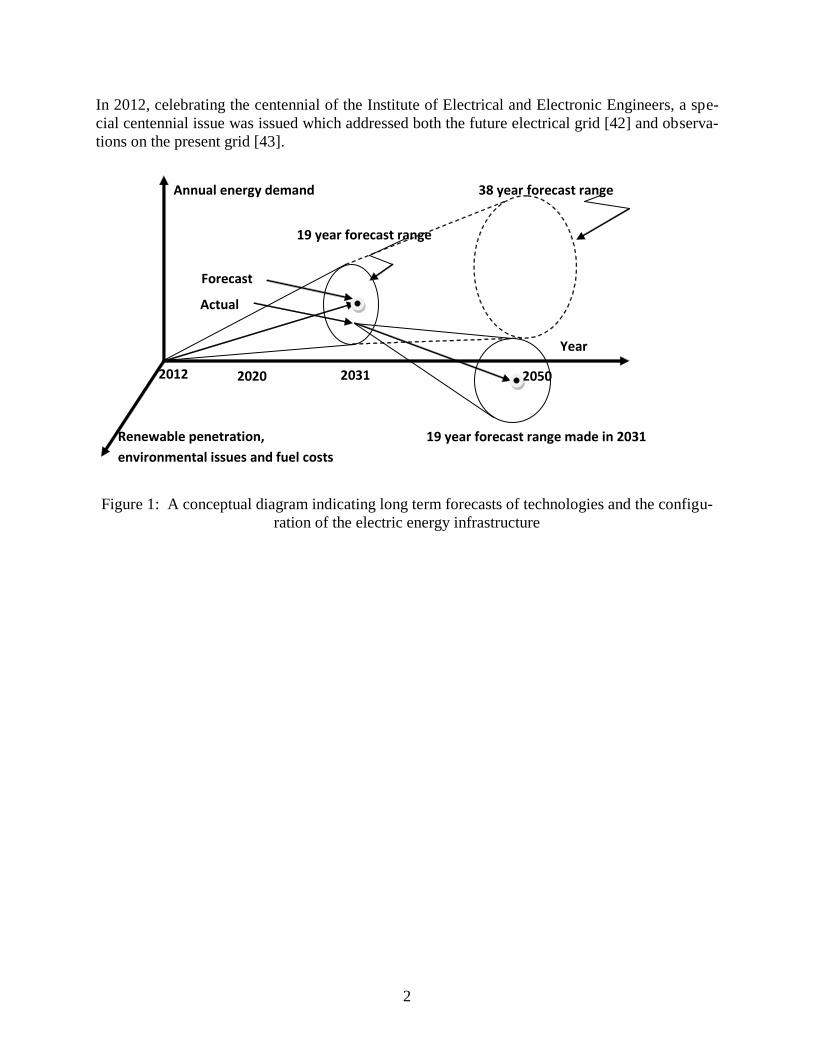
The intent of the paper is an ‘over the horizon view’ of the segment of the electric energy field,
accounting for eventualities in hardware, digital technologies, political actions, public participa-
tion, and the growth of electric energy use. Fig. 1 shows a pictorial of the concept of long range
forecasts of the infrastructure of electric energy 2012 – 2050. The intent of the pictorial is that
assumptions and forecasts made in 2012 may result in an increasing ‘cone of uncertainty’ as the
years evolve, and uncertainties may be realized. The uncertainty relates to fuel costs, environ-
mental issues, mandates for renewable resource penetration, technological developments and a
host of other factors. At points in the future, e.g. in 2031, actual scenarios could be used to
evolve other forecasts of scenarios. It is expected that a 19 year forecast would be more accurate
in its predictions and approximations as compared to, for example, a 38 year forecast. This is
shown pictorially in Fig. 1.
2
In 2012, celebrating the centennial of the Institute of Electrical and Electronic Engineers, a spe-
cial centennial issue was issued which addressed both the future electrical grid [42] and observa-
tions on the present grid [43].
Figure 1: A conceptual diagram indicating long term forecasts of technologies and the configu-
ration of the electric energy infrastructure
2012 2050 2031
Year
Renewable penetration,
environmental issues and fuel costs
Annual energy demand
19 year forecast range
2020
38 year forecast range
19 year forecast range made in 2031
Forecast
Actual
3
1. The Opportunity and the Challenge
1.1 Research Opportunities in Transmission Engineering
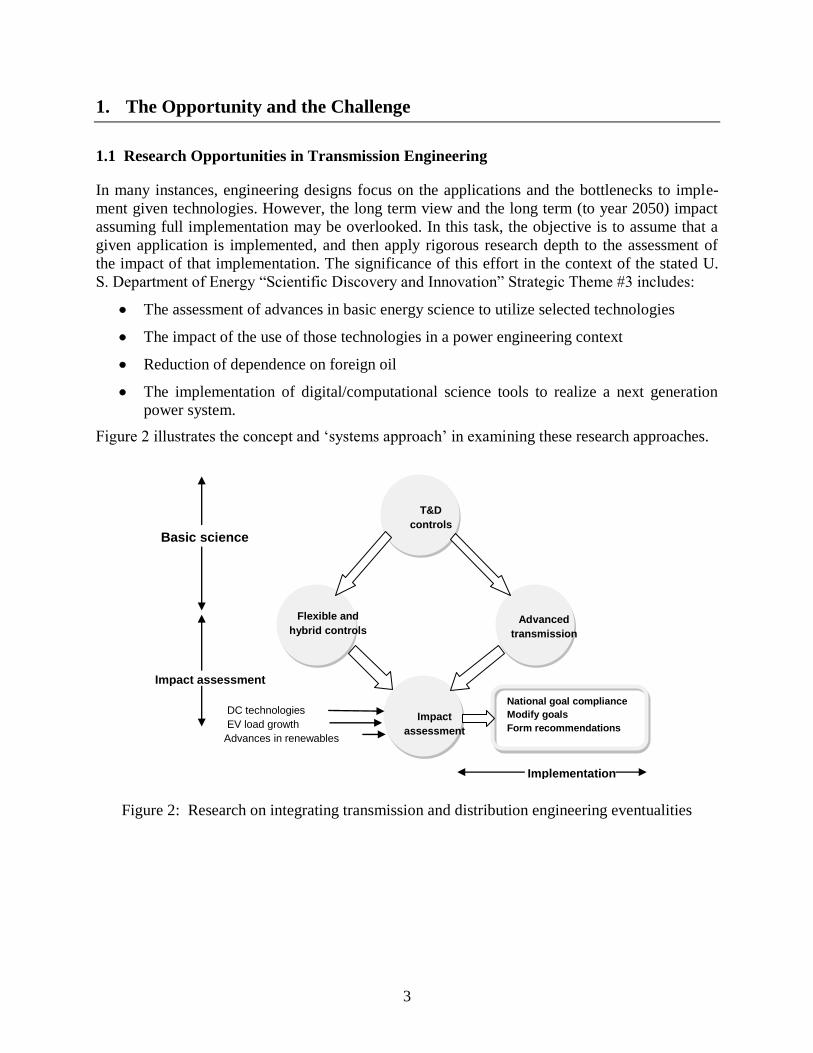
In many instances, engineering designs focus on the applications and the bottlenecks to imple-
ment given technologies. However, the long term view and the long term (to year 2050) impact
assuming full implementation may be overlooked. In this task, the objective is to assume that a
given application is implemented, and then apply rigorous research depth to the assessment of
the impact of that implementation. The significance of this effort in the context of the stated U.
S. Department of Energy “Scientific Discovery and Innovation” Strategic Theme #3 includes:
The assessment of advances in basic energy science to utilize selected technologies
The impact of the use of those technologies in a power engineering context
Reduction of dependence on foreign oil
The implementation of digital/computational science tools to realize a next generation
power system.
Figure 2 illustrates the concept and ‘systems approach’ in examining these research approaches.
Figure 2: Research on integrating transmission and distribution engineering eventualities
DC technologies
EV load growth
Advances in renewables
National goal compliance
Modify goals
Form recommendations
Basic science
Impact assessment
Implementation
Flexible and
hybrid controls
Impact
assessment
Advanced
transmission
T&D
controls
4
1.2 The Research Issues
The main research issues addressed in this area are:
Fundamental Transmission Engineering Challenges
These challenges and research issues include high voltage DC technologies (including voltage
source converter technologies, multi-terminal HVDC, networked DC, limitations imposed by DC
circuit interruption limitations and difficulties): new technologies in overhead transmission such
as high temperature low sag conductors, non-circular cross-section conductors, compact phase
spacing designs, new insulation concepts, ultra high voltage (e.g., > 1000 kV), high phase order
(e.g., six phase and higher phase order): the role of energy storage and transmission expansion
and design: underground cable technologies. It is expected that through the year 2050, continen-
tal transmission connections are likely (including the connections already made between Canada
and the United States, but also considerably enhanced connections between Mexico and the
United States).
The Role of Energy Storage
In the integration of renewable resources into interconnected power systems, a key consideration
is the role of energy storage. This is the case because of the variability of wind and solar energy
resources. As convenient storage is augmented into the systems, the energy available system
wide may be stored or discharged based on need (i.e., based on the price of one megawatt-hour).
The role of storage includes alleviating transmission expansion, reducing generation reserve re-
quirements, maximizing the use of variable generation resources such as wind and solar. The
negative side of this observation is that energy storage generally involves multiple energy con-
versions (e.g., DC/AC), consideration of losses in the energy storage and conversion processes,
and the cost of energy storage devices. Concomitantly there is the issue of the inconvenience of
large scale energy storage devices. The main elements of energy storage deployment, in the
2012–13, time frame are that any one specific advantage of energy storage may not have a favor-
able cost to benefit ratio, and the commercial unavailability of large scale storage units may not
favor their use. Pumped hydro is an obvious solution, but this technology has limited applicabil-
ity due to the land, topography, and water resources required. Moving to the time frame 2033,
one can envision breakthroughs in energy storage and its commercial viability. The main break-
throughs needed are:
Resolution of unfavorable cost to benefit ratios, either by advances in storage technolo-
gies, acceptance of governmental subsidies, consolidation of benefits, or otherwise realiz-
ing the benefits of storage.
Realization of electric vehicle technologies that include distributed storage of energy in
the distribution system.
Increases in renewable penetration with the percentage of variable resources being high
enough to render the cost to benefit ratio of energy storage to favorable ranges.
In addition to the hardware oriented issues of energy storage, there are also needed system theory
breakthroughs. This is the case since the scheduling of charge/discharge regimes requires the op-
timization of a nonlinear objective function (namely service cost over a specified time horizon)
constrained by equality constraints (e.g., conservation of power at all buses, conservation of en-
5
ergy over a given charge cycle), and also inequality constraints (e.g., transmission line and com-
ponent loading limits, various operating limits, compliance with energy storage device ratings).
The scheduling problem is made more complex by including system losses, storage unit and
converter losses, energy price uncertainty. One approach is the use of quadratic programming to
minimize the constrained cost to deliver energy to specific system buses, and another approach
uses a modification of quadratic programming by adding Kuhn-Tucker terms to the objective
function. Reference [44] addresses some of these points with regard to stored energy scheduling.
Transmission Overlay Plans
Research into a coordinated national transmission plan and overlay is important to the long term
future of power engineering in the United States. The basic design of such an overlay is the main
element of this area. Included is the development of an associated design process to facilitate the
growth of wind, solar, nuclear, geothermal, and clean-coal generation over the next 40 years. Re-
search in this area includes: model development: evaluation and development of future alterna-
tives (e.g., about 7 significantly different “futures” in terms of load growth and generation in-
vestment). The generation investment “future” will depend on which generation technology is
emphasized (relative to a reference case): reference, high wind, high solar, high geo-thermal,
high nuclear, high clean-coal, and high natural gas: the evaluation of alternative transmission
technologies including HVAC overhead (500 kV, 765 kV), HVDC overhead (600 kV, 800 kV),
HVDC under-ground (including standard cable, gas insulated cable, and superconducting high-
temperature); optimization (e.g., using NETPLAN software will be used to identify the most ef-
fective (cost, resiliency, and emissions) transmission plan for each future); and robust testing of
alternative plans. Important to this area is the determination of which plan is most robust to fu-
ture uncertainties.
Robust and Dynamic Reserve Requirements
There are opportunities to greatly improve upon today’s methods of determining reserve levels
and reserve zones. There is a need for more systematic ways to determine the optimal reserve
requirements. Also contemporary practices do not reflect the true flexibility that exists in the grid
and they do not account for the uncertainty of future resources (wind, solar, PHEVs). Zones to-
day are static and do not change with the operational conditions of the grid. Research objectives
in this area are: the examination of contemporary practice in calculating reserve requirements:
analysis of the impact on reserve requirements due to the integration of new resources and pro-
posing of necessary changes: analysis of the impact on reserve requirements due to the devel-
opment of a more flexible transmission grid and proposing of necessary changes: optimal de-
termination of reserve zones and analysis of dynamic reserve zones; and the risk assessment of
reserve requirements and the proposed changes.
Wide Area Control
The main research areas in wide area control are: future wide-area controls and benefits; voltage
controls; wide-area oscillatory controls; and wide-area angle stability controls. Subtopics for
wide area control research are:
1. Control framework and formulation in the future power system
2. Merits of different controllers and recommendations

6
3. Substation level voltage controllers
4. Coordinated wide-area voltage controllers
5. Formulation of real-time designs for oscillatory controls
6. Distributed formulations of oscillatory controls
7. Coordinated designs for oscillatory controls
8. Formulation and first investigation of coordinated wide-area angle stability controls.
The research horizons in each of these areas are discussed in the subsequent sections. The time
horizon used is to year 2050.
7
2. The Future Grid
In this section, a discussion of a view of the future grid in the United States through year 2050 is
discussed. The intent is an ‘over horizon’ view of the future grid. The discussion is organized
into four subsections which are correlated to the four areas discussed in the previous section.
2.1 Fundamental Transmission Engineering Challenges
Fundamental transmission engineering challenges facing the United States at this time include:
Integration of renewable resource generation.
Maintaining reliability at historical levels despite restrictions in transmission expansion
and the variability of wind resources.
The utilization of newly developed transmission technologies which include high temper-
ature, low sag overhead conductors: ultra-high voltage transmission cables suitable for
high population density locations and marine applications.
Utilization of compact transmission designs, and potentially developing new standards
for overhead conductor spacing to attain high power use of rights of way.
Investigation of the relaxation or modification of design standards to obtain the best
tradeoff of reliability, safety, cost, and land use. This area includes the potential loosen-
ing of the tight frequency standards in North America. Another area is the relaxation of
some protection practices, e.g. protection of certain transmission system components.
Rendering the transmission system robust to problematic conditions. This area is a wide
area which exceeds the bounds of traditional transmission engineering. For example, how
would the transmission system react to a large earthquake in California or the central
Midwest? There are some transmission designs which are more robust than others to ac-
commodate natural occurrences, and these need to be examined to include more exten-
sive use of underground technologies, wider disbursal of transmission facilities, decen-
tralization of substations.
The full development of transmission expansion technologies, including multi-objective
optimization of cost.
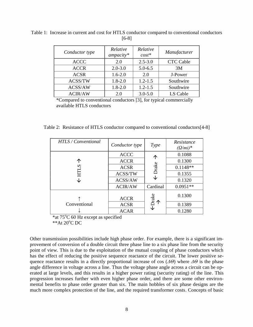
As an example of the foregoing discussion, high temperature low sag (HTLS) overhead conduc-
tors may be used to improve the loadability of circuits. Mainly, HTLS designs have been used to
alleviate thermal problems with existing circuits. A typical HTLS conductor can handle 1.6 to 3
times the current of a similar conventional conductor [3]. This increase in current rating comes at
a dollar cost of up to 6.5 times that of a conventional conductor (see Table 1.1). Comparing the
alternatives of a single HTLS circuit versus a double circuit conventional line, HTLS may have
higher I2R losses as a consequence of the higher current but comparable resistance. Table II con-
tains representative values of HTLS conductor resistance values with the resistance of similar
conventional conductors shown for comparison. Apparently the impact in phase angle security
rating of HTLS circuits is very low; however, if the HTLS design is augmented with compact
spacing of conductors, there could be a substantial increase in the security limit of a line.
8
Table 1: Increase in current and cost for HTLS conductor compared to conventional conductors
[6-8]
Table 2: Resistance of HTLS conductor compared to conventional conductors[4-8]
Other transmission possibilities include high phase order. For example, there is a significant im-
provement of conversion of a double circuit three phase line to a six phase line from the security
point of view. This is due to the exploitation of the mutual coupling of phase conductors which
has the effect of reducing the positive sequence reactance of the circuit. The lower positive se-
quence reactance results in a directly proportional increase of cos (ΔΘ) where ΔΘ is the phase
angle difference in voltage across a line. Thus the voltage phase angle across a circuit can be op-
erated at large levels, and this results in a higher power rating (security rating) of the line. This
progression increases further with even higher phase order, and there are some other environ-
mental benefits to phase order greater than six. The main hobbles of six phase designs are the
much more complex protection of the line, and the required transformer costs. Concepts of basic
Conductor type Relative
ampacity*
Relative
cost* Manufacturer
ACCC 2.0 2.5-3.0 CTC Cable
ACCR 2.0-3.0 5.0-6.5 3M
ACSR 1.6-2.0 2.0 J-Power
ACSS/TW 1.8-2.0 1.2-1.5 Southwire
ACSS/AW 1.8-2.0 1.2-1.5 Southwire
ACIR/AW 2.0 3.0-5.0 LS Cable
*Compared to conventional conductors [3], for typical commercially
available HTLS conductors
HTLS / Conventional Conductor type Type
Resistance
(Ω/mi)*
H
TL
S
ACCC
Dra
ke
0.1088
ACCR 0.1300
ACSR 0.1148**
ACSS/TW 0.1355
ACSS/AW 0.1320
ACIR/AW Cardinal 0.0951**
↑
Conventional
↓
ACCR
D
rake
0.1300
ACSR 0.1389
ACAR 0.1280
*at 75oC 60 Hz except as specified
**At 20oC DC
9
transmission topology that are less considered that six-phase designs include: true polyphase
designs, e.g., twelve phase or higher in which electromagnetic field cancellation occurs better
than lower phase order, but transformer connections and protection become problematic: non-
standard frequency designs, e.g., line frequencies higher than 60 Hz for short runs and few mag-
netic components but lower than 60 Hz for longer runs and instances of many magnetic compo-
nents: truly variable frequency designs in which the line frequency is adjusted in time according
to loading and injected power operating conditions. Some of these concepts may have applica-
tion in wind farms where nonstandard frequency or phase order are possible because of the use
of electronic converters.
High voltage DC advances may play a significant role in transmission engineering in the future.
High voltage DC (HVDC) transmission technologies have been recognized as effective in trans-
mission systems for long distance, bulk energy applications, and also in back-to-back intercon-
nection of asynchronous AC transmission systems. There are innovative HVDC designs that
have not been widely applied in transmission engineering, however, and these include:
Multiterminal HVDC systems
Meshed (networked) systems
Voltage source converter (VSC) applications in HVDC.
Motivation for examination of these technologies include: paucity of viable rights-of-way for
added transmission paths; expected added generation resources far from load centers (e.g., re-
newable resources such as wind and solar); continued improvement in system reliability by em-
ploying asynchronous connections of large interconnection areas.
The Western interconnection in North America contains many examples of potential applications
for HVDC technologies, both in the milieu of long, bulk energy transport and in asynchronous
ties. By no means is the Western interconnection unique in this regard, but it does serve as a val-
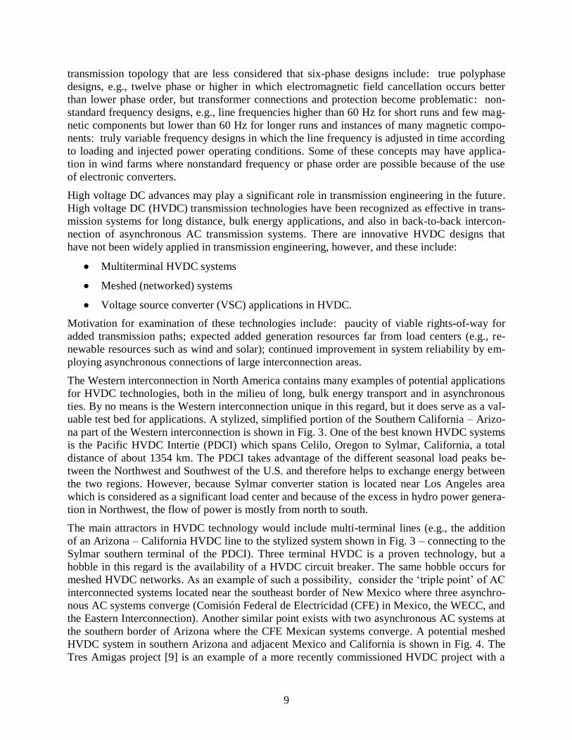
uable test bed for applications. A stylized, simplified portion of the Southern California – Arizo-
na part of the Western interconnection is shown in Fig. 3. One of the best known HVDC systems
is the Pacific HVDC Intertie (PDCI) which spans Celilo, Oregon to Sylmar, California, a total
distance of about 1354 km. The PDCI takes advantage of the different seasonal load peaks be-
tween the Northwest and Southwest of the U.S. and therefore helps to exchange energy between
the two regions. However, because Sylmar converter station is located near Los Angeles area
which is considered as a significant load center and because of the excess in hydro power genera-
tion in Northwest, the flow of power is mostly from north to south.
The main attractors in HVDC technology would include multi-terminal lines (e.g., the addition
of an Arizona – California HVDC line to the stylized system shown in Fig. 3 – connecting to the
Sylmar southern terminal of the PDCI). Three terminal HVDC is a proven technology, but a
hobble in this regard is the availability of a HVDC circuit breaker. The same hobble occurs for
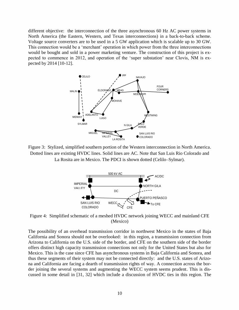
meshed HVDC networks. As an example of such a possibility, consider the ‘triple point’ of AC
interconnected systems located near the southeast border of New Mexico where three asynchro-
nous AC systems converge (Comisión Federal de Electricidad (CFE) in Mexico, the WECC, and
the Eastern Interconnection). Another similar point exists with two asynchronous AC systems at
the southern border of Arizona where the CFE Mexican systems converge. A potential meshed
HVDC system in southern Arizona and adjacent Mexico and California is shown in Fig. 4. The
Tres Amigas project [9] is an example of a more recently commissioned HVDC project with a
10
different objective: the interconnection of the three asynchronous 60 Hz AC power systems in
North America (the Eastern, Western, and Texas interconnections) in a back-to-back scheme.
Voltage source converters are to be used in a 5 GW application which is scalable up to 30 GW.
This connection would be a ‘merchant’ operation in which power from the three interconnections
would be bought and sold in a power marketing venture. The construction of this project is ex-
pected to commence in 2012, and operation of the ‘super substation’ near Clovis, NM is ex-
pected by 2014 [10-12].
Figure 3: Stylized, simplified southern portion of the Western interconnection in North America.
Dotted lines are existing HVDC lines. Solid lines are AC. Note that San Luis Rio Colorado and
La Rosita are in Mexico. The PDCI is shown dotted (Celilo–Sylmar).
Figure 4: Simplified schematic of a meshed HVDC network joining WECC and mainland CFE
(Mexico)
The possibility of an overhead transmission corridor in northwest Mexico in the states of Baja
California and Sonora should not be overlooked: in this region, a transmission connection from
Arizona to California on the U.S. side of the border, and CFE on the southern side of the border
offers distinct high capacity transmission connections not only for the United States but also for
Mexico. This is the case since CFE has asynchronous systems in Baja California and Sonora, and
thus these segments of their system may not be connected directly: and the U.S. states of Arizo-
na and California are facing a dearth of transmission rights of way. A connection across the bor-
der joining the several systems and augmenting the WECC system seems prudent. This is dis-
cussed in some detail in [31, 32] which include a discussion of HVDC ties in this region. The
CELILO
MALIN
MIDWAY
SYLMAR
ADELANTO
MIGUEL
IPP
LUGO
LA ROSITA
IMPERIAL
VALLEY
N GILA
MOHAVE
ELDORADO MEAD
PALO VERDE
WESTWING
MOENKOPI
FOUR CORNERS
NAVAJO
SAN LUIS RIO
COLORADO
NORTH GILA
PUERTO PEÑASCO
IMPERIAL
VALLEY
SAN LUIS RIO
COLORADO To CFE
AC/DC
converter
500 kV AC
DC
mesh
CFE
WECC

11
same issues occur near El Paso TX – Ciudad Juarez, Chihuahua where the Texas interconnec-
tion, CFE, and WECC converge.
2.2 Transmission Overlay Plans
The levelized cost of energy production for renewables (e.g., wind, solar, and deep geothermal)
varies dramatically from one part of the country to another, and unlike energy in coal, natural
gas, and uranium which may be moved electrically or in other ways (e.g., by rail and truck for
coal, and by pipeline for natural gas), the only way to move renewable energy is by electric
transmission. These two attributes of renewables, the heavy influence of location on their eco-
nomic viability and their complete dependence on electric transmission for energy transfer, in-
creases benefits derived from interregional transmission in future scenarios where renewables
comprise an increased percentage in the national generation portfolio. Yet, today, the ability to
move electric energy interregionally is limited to the capacity of the existing transmission sys-
tem, a system designed largely to serve intraregional needs from fossil- and nuclear-based gener-
ation for which production costs are relatively flat from one region to another. Our nation’s abil-
ity to utilize renewables with least cost depends on the existence of high capacity interregional
transmission. This point was illustrated in [35] where optimization software was used to show
that if generation resources were restricted to wind, photovoltaic (PV), concentrated solar ther-
mal (CST), and geothermal over the next 40 years, the most economic resource allocation would
require over 170 GW of interregional transmission to move electric energy from the most attrac-
tive renewable resource locations to the load centers. Figure 5 illustrates the locations for this
capacity, its flow direction, together with the generated (left-hand bars, with green indicating re-
newable energy) and demanded energy (right-hand bars) in each region, in units of quads (1
quad=1×10¹⁵
BTU=293,080 GWh). An effectively designed high-capacity transmission overlay
would also bring benefits in terms of operational resilience to unforeseen events and in terms of
future planning flexibility.

12
Figure 5: Illustration of transmission capacity needs for a renewable-heavy generation portfolio
Building transmission at an interregional or national scale will require use of high-capacity
transmission technologies. There are two proven technologies that are operational and can be
purchased and built today, 765 kV AC and ±800 kV DC. If a 765 kV line is equipped with ade-
quate capacitive compensation every 200 miles or so, it can reach capacities of 3100 MW. DC at
±800 kV provides about 6400 MW capacity per bipole configuration. A third technology is su-
perconducting DC; though a ±200 kV DC system is being marketed having capacity of 5000
MW or more per bipole configuration, it is yet to see commercial implementation. Although
there is one instance of an AC transmission line built at 1150 kV in Russia and another built at
1000 kV in Japan, both of the lines are now being operated at 500 kV. Today, the only AC
transmission operated above 765 kV is a 640 km, 1000 kV line, with capacity 5000 MW, in Chi-
na which began commercial operation in January, 2009.
Although DC applications require high-cost converter stations at the terminals, the per-mile line
cost is well below that of an equivalent capacity AC circuit. Therefore, in overhead applications,
for relatively short distances, high capacity transmission is usually more economic with AC. DC
transmission becomes more economic for distances beyond about 400 miles. High capacity un-
derground AC transmission is generally not feasible because of the high charging currents gener-
ated. Therefore, any high capacity underground application today must be DC.
Although overhead transmission is generally much less expensive than underground, it may be
that public resistance to overhead transmission significantly limits use of overhead for interre-
gional transmission design. A DC (either ±800 kV or superconducting ±200 kV) underground
13
design could meet capacity needs while incurring much less public resistance. The main problem
with such a design, referred to as a multi-terminal DC line, is that interconnection between the
line and the AC grid at locations other than the terminals significantly increases its cost because
additional converter stations are required. Thus, today’s high voltage (HV) DC designs generally
have poor “on/off-ramp” capabilities, a feature which is of some concern in order to provide that
the transmission yields value to intermediate locations along its path, an issue of importance be-
cause future renewable plants are likely to be distributed within a region.
There are two types of solutions to this problem. An obvious approach is to bring down the cost
of the converter stations. Many researchers are actively pursuing this approach, and significant
progress has been made using voltage source converters (VSC). The major difference between
VSC-based and thyristor-based HVDC is that the latter is line-commutated whereas the former is
forced-commutated via control circuits driven by pulse-width modulation. A primary limitation
which must be overcome for VSC-based multi-terminal DC lines is to develop an economically
attractive means to increase their power handling capability which is presently limited by the
power ratings of the insulated gate bipolar transistors (IGBT) on which they depend.
It is likely that long-distance bulk transmission design at the interregional level would necessari-
ly include an integration of both HVDC transmission, to take advantage of its lower cost per
GW-mile, and extra high voltage (EHV) AC transmission, to obtain the flexibility AC provides
in facilitating the numerous interconnections of new generation projects and load centers, and
that systems will be designed so that the two are complementary assets. This perspective is con-
sistent with conclusions made in two recent studies [36, 37] which demonstrated that hybrid 500-
765 kV AC and HVDC systems were effective solutions for a 20% renewable energy penetration
in the Eastern Interconnection. Various network topologies should be considered, including those
with multi-terminal DC lines, to identify those integrated HVDC/EHVAC designs which have
low investment costs and effective performance. For example, one or more three-terminal DC
lines (either ±800 kV DC or ±200 kV superconducting) could be built in parallel with a single
high capacity AC overhead circuit. Similar discussions on this issue include a European super-
grid [38, 39] and a design for a North Sea DC network [40].
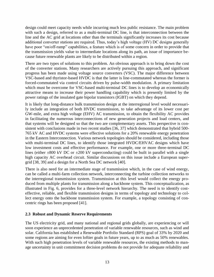
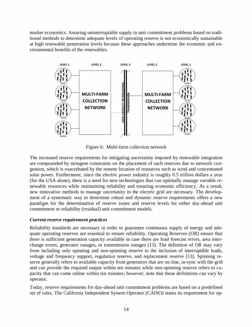
There is also need for an intermediate stage of transmission which, in the case of wind energy,
can be called a multi-farm collection network, interconnecting the turbine collection networks to
the interregional transmission system. Transmission at this level would collect the energy pro-
duced from multiple plants for transmission along a backbone system. This conceptualization, as
illustrated in Fig. 6, provides for a three-level network hierarchy. The need is to identify cost-
effective, reliable, and flexible transmission designs in terms of topology and technology to col-
lect energy onto the backbone transmission system. For example, a topology consisting of con-
centric rings has been proposed [41].
2.3 Robust and Dynamic Reserve Requirements
The US electricity grid, and many national and regional grids globally, are experiencing or will
soon experience an unprecedented penetration of variable renewable resources, such as wind and
solar. California has established a Renewable Portfolio Standard (RPS) goal of 33% by 2020 and
some regions are aiming for even loftier goals in future years, up to as much as 50% renewables.
With such high penetration levels of variable renewable resources, the existing methods to man-
age uncertainty in unit commitment decision problems do not provide for adequate reliability and
14
market economics. Assuring uninterruptable supply in unit commitment problems based on tradi-
tional methods to determine adequate levels of operating reserve is not economically sustainable
at high renewable penetration levels because these approaches undermine the economic and en-
vironmental benefits of the renewables.
Figure 6: Multi-farm collection network
The increased reserve requirements for mitigating uncertainty imposed by renewable integration
are compounded by stringent constraints on the placement of such reserves due to network con-
gestion, which is exacerbated by the remote location of resources such as wind and concentrated
solar power. Furthermore, since the electric power industry is roughly 0.5 trillion dollars a year
(for the USA alone), there is a need for new technologies that can optimally manage variable re-
newable resources while maintaining reliability and ensuring economic efficiency. As a result,
new innovative methods to manage uncertainty in the electric grid are necessary. The develop-
ment of a systematic way to determine robust and dynamic reserve requirements offers a new
paradigm for the determination of reserve zones and reserve levels for either day-ahead unit
commitment or reliability (residual) unit commitment models.
Current reserve requirement practices
Reliability standards are necessary in order to guarantee continuous supply of energy and ade-
quate operating reserves are essential to ensure reliability. Operating Reserves (OR) ensure that
there is sufficient generation capacity available in case there are load forecast errors, area inter-
change errors, generator outages, or transmission outages [13]. The definition of OR may vary
from including only spinning and non-spinning reserve to the inclusion of interruptible loads,
voltage and frequency support, regulation reserve, and replacement reserve [13]. Spinning re-
serve generally refers to available capacity from generators that are on-line, in-sync with the grid
and can provide the required output within ten minutes while non-spinning reserve refers to ca-
pacity that can come online within ten minutes; however, note that these definitions can vary by
operator.
Today, reserve requirements for day-ahead unit commitment problems are based on a predefined
set of rules. The California Independent System Operator (CAISO) states its requirement for op-
Windfarm
Windfarm
Windfarm
Windfarm
Windfarm
Windfarm
Windfarm
Windfarm
MULTI-FARM
COLLECTION
NETWORK
MULTI-FARM
COLLECTION
NETWORK
HIG
H C
AP
AC
ITY
IN
TER
EGIO
NA
L
TR
AN
SMIS
SIO
N
LEVEL 1 LEVEL 2 LEVEL 3 LEVEL 2 LEVEL 1
15
erating reserve in [14]. The operating reserve requirement in CAISO is the maximum of OR1
and OR2, then plus 100% of the non-firm (interruptible) imports. OR1 is calculated for each re-
serve zone and is equal to 5% of the demand met by hydro resources plus 7% of the demand met
by non-hydro resources. OR2 is based on the worst single contingency. The worst contingency is
based on the largest committed generator or the largest net tie-line import. The Western Elec-
tricity Coordinating Council (WECC) establishes its own guidelines for contingency reserve, i.e.,
spinning and non-spinning reserve, in [15].
Historically, ad-hoc or rule-of-thumb methods have been used to determine reserve require-
ments. The most basic rule-of-thumb is that the amount of reserves must be at least as great as
the single worst contingency, as can be identified by CAISO’s OR2 rule above and this is the
approach taken by the largest public utility in the USA, Tennessee Valley Authority (TVA). This
rule is commonly adopted due to the N-1 requirements imposed on the electric power sector by
the North American Electric Reliability Corporation (NERC), which is the appointed Electric
Reliability Organization (ERO) as designated by the Federal Energy Regulatory Commission
(FERC). While the N-1 requirement is a robust requirement, N-1 reliability is not explicitly en-
forced inside unit commitment and simply acquiring reserve equal to the largest single contin-
gency falls short of guaranteeing N-1. Due to congestion, there is no guarantee that the reserve
can be delivered when and where needed and, hence, simply procuring a quantity of reserve
equal to the largest contingency does not guarantee N-1. As a result, one method to adjust the
level of reserve is to rely on historical information that reflects system loading conditions in or-
der to avoid involuntary load shedding. The problem with the use of historical information is that
wide-spread load shedding is not a common event and it is not possible to determine the actual
optimal amount of reserves based on historical information when the grid and resources are ever
changing. Another common approach is to relate the level of congestion in the system to the lev-
el of reserve. The Electric Reliability Council of Texas (ERCOT) uses historical information to
estimate the level of congestion as well as identify key congested transmission lines, Commer-
cially Significant Constraints (CSCs), in order to define the reserve zones, [16]. Using historical
information to estimate the level of congestion is imprecise because: a) the network topology
changes as there are constant network outages, which affects the power flow; b) congestion can
vary greatly over the course of a day let alone vary substantially in comparison to average histor-
ical information. Finally, future grid conditions will not be represented well based on current his-
torical information. The addition of large amounts of variable renewable resources, new demand
side resources and participation, e.g., PHEVs, and advanced technologies being developed for
the smart grid will change grid operations and grid characteristics.
With high levels of variable generation due in the future, the National Renewable Energy Labor-
atory (NREL) suggest a new rule for operating reserves: 3% of load and 5% of variable re-
sources (wind and solar) for spinning and non-spinning reserve. However, these numbers are
again based on ad-hoc, rule-of-thumb procedures and it is a static, universal rule. To date there is
no mathematical framework for the determination of reserve requirements in relation to the spe-
cial characteristics of variable renewable resources. While it is understood that these currently
proposed approaches are imprecise, there has not been enough attention given to improving the
methods to determine reserve requirements and these past procedures will not suffice in future
years.
16
Stochastic and Robust Optimization Approaches to Endogenously Determined Reserves
Much of the current research that aims to address the future concerns of variable renewable re-
sources focuses on the use of stochastic optimization, which endogenously determines reserves.
Multiple stochastic optimization approaches have been proposed, including, but not limited to,
scenario selection techniques to reduce the number of scenarios as well as chance-based con-
straints, [17]-[25]. While stochastic unit commitment approaches have the benefit of ensuring
reliable solutions relative to the modeling complexity, the drawback is the high computational
complexity that is required to ensure highly reliable solutions. Therefore, the computational chal-
lenges of stochastic programming limit the level of potential modeling detail and, hence, limit
the reliability of the solutions. Robust optimization is another approach that has been recently
proposed as a method to improve the robustness of unit commitment solutions. Robust optimiza-
tion guarantees a feasible solution for any possible realization in the modeled uncertainty set.
With robust optimization, instead of assuming a probability distribution for uncertain parameters,
an uncertainty set is predetermined to cover the possible realizations. Recently, more attention
has been given to the application of robust optimization in the power systems sector by Bertsi-
mas et al., [26], Jiang et al., [27], and Mejia et al., [28]. However, similar to stochastic optimiza-
tion, robust optimization today is still too computationally challenging for large-scale unit com-
mitment models.
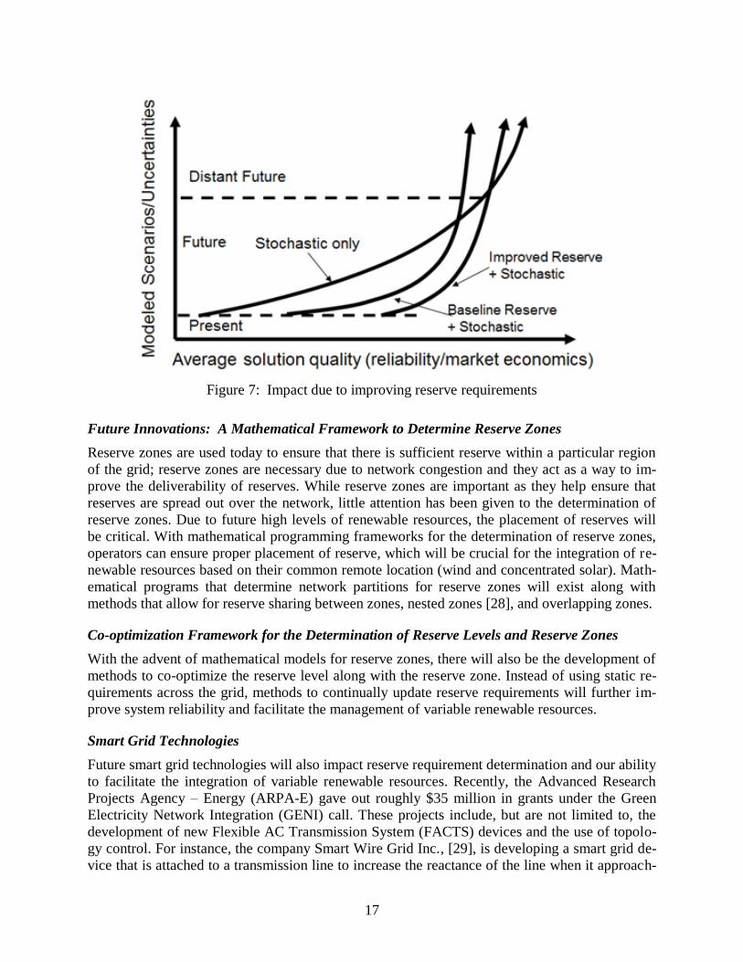
Balancing Stochastic Approaches with Deterministic Reserve Requirements
While stochastic and robust optimization techniques are preferred since they endogenously de-
termine reserve, today, and in the future, these methods are, by themselves, incapable of ensuring
efficient and reliable unit commitment solutions. Due to the computational complexity of sto-
chastic approaches, there will continue to be a reliance on reserve requirements due to the neces-
sity to balance model complexity with proxy methods that are computationally tractable. As
demonstrated by the curves in Fig. 7, solution quality can increase with added stochastic model-
ing; however, this comes at the cost of modeling complexity, i.e., computational time. The de-
velopment of robust and dynamic reserve requirements can be used in conjunction with scenario
selection of stochastic programming or uncertainty set definition of robust optimization, in order
to provide the best solution attainable with the existing computational capability to date. Fur-
thermore, with a novel mathematical framework to determine more reliable and economically
efficient reserves, our ability to deal with uncertainties will improve and, thus, it will increase the
maximum penetration level of variable renewable resources.
17
Figure 7: Impact due to improving reserve requirements
Future Innovations: A Mathematical Framework to Determine Reserve Zones
Reserve zones are used today to ensure that there is sufficient reserve within a particular region
of the grid; reserve zones are necessary due to network congestion and they act as a way to im-
prove the deliverability of reserves. While reserve zones are important as they help ensure that
reserves are spread out over the network, little attention has been given to the determination of
reserve zones. Due to future high levels of renewable resources, the placement of reserves will
be critical. With mathematical programming frameworks for the determination of reserve zones,
operators can ensure proper placement of reserve, which will be crucial for the integration of re-
newable resources based on their common remote location (wind and concentrated solar). Math-
ematical programs that determine network partitions for reserve zones will exist along with
methods that allow for reserve sharing between zones, nested zones [28], and overlapping zones.
Co-optimization Framework for the Determination of Reserve Levels and Reserve Zones
With the advent of mathematical models for reserve zones, there will also be the development of
methods to co-optimize the reserve level along with the reserve zone. Instead of using static re-
quirements across the grid, methods to continually update reserve requirements will further im-
prove system reliability and facilitate the management of variable renewable resources.
Smart Grid Technologies
Future smart grid technologies will also impact reserve requirement determination and our ability
to facilitate the integration of variable renewable resources. Recently, the Advanced Research
Projects Agency – Energy (ARPA-E) gave out roughly $35 million in grants under the Green
Electricity Network Integration (GENI) call. These projects include, but are not limited to, the
development of new Flexible AC Transmission System (FACTS) devices and the use of topolo-
gy control. For instance, the company Smart Wire Grid Inc., [29], is developing a smart grid de-
vice that is attached to a transmission line to increase the reactance of the line when it approach-
18
es its thermal limit. There is also the Robust Adaptive Topology Control (RATC) project, [30],
that will investigate the utilization of transmission assets to control, via transmission switching,
the flow of power. These technologies will enable operators to have more control over the flow
of power across the grid. Such technologies increase our ability to further utilize transmission
infrastructure by mitigating congestion and, thus, these technologies will improve the delivera-
bility of reserves, which will further facilitate the integration of renewables and will bring down
the cost imposed on system operations due to renewables. Future mathematical frameworks for
the determination of reserve requirements should be capable of incorporating such smart grid
technologies when determining reserves.
2.4 Wide Area Control
The nature of the power system is expected to undergo dramatic changes in the next four dec-
ades. Owing to environmental concerns and possibly economic reasons, a significant portion of
electric power generation is expected to be from renewable generation sources by 2050. Bulk
synchronous generators which produce most of the generation in present day power system will
play lesser roles, though nuclear energy may still play a substantial role that will be represented
by bulk synchronous machines. On the demand side, the nature of the consumer loads will likely
undergo dramatic changes where each consumer residence may serve as energy source or energy
sink at different times of day with flexible interface with the bulk power system. In the future
power system, substations may play crucial role in managing thousands of complex residential
loads (or sources) along with other local energy sources that lessen the dependence on the power
transmission grid. Therefore, each substation of the future power system may play the role of
present day control centers.
Controls and system protection in such a future power system will need to be thought out care-
fully. It is important that road maps be developed now for transitioning into the future power grid
in a smooth fashion. The controls naturally divide into two kinds: a) substation controls and b)
power grid controls:
a) Substation Controls: Substation controls can be expected to be mostly based on local
measurements with supervisory guidance from regional control centers. The substation
controller will need to manage local power balancing issues as well as ensuring stability
and reliability of the local power system with no adverse effects on the large intercon-
nected grid. Diverse power electronic controls in renewable power sources as well as in
residential power systems will render the stability analysis of the substation dynamic
models very complex. Traditional power system stability designs that assume the availa-
bility of detailed dynamic models of bulk power generators. These designs may need to
be reformulated to be more of real-time observer based designs that estimate the essential
dynamic features of the power electronic models of the generators and loads in the future
power system. In managing the local resources at a substation, limitations of communica-
tion network will need to be included in the controller designs. It is also important to de-
velop well-defined stability criteria or standards for local resources (such as power elec-
tronic controls) that ensure that the substation controls do not adversely impact on the re-
liability of the bulk power system.
Voltage stability controls will be more challenging because the power electronic devices
may impose heavy burden on reactive power demands at the substation. At the same

19
time, shunt capacitor banks and reactor banks as well as transmission line impedances
may introduce challenging subsynchronous resonance issues affecting integrity of wind
farms in the future power system. Analysis of these issues may require measurement de-
vices at high sampling rates [34]. Each substation may be required to operate in islanded
operation whenever needed, that may enforce special control designs on frequency con-
trol and angle stability issues at each substation especially in islanded configuration.
b) Power Grid Controls: Grid control center of the future will be responsible for ensuring
reliable and efficient operation of the large power grid, much like in the present day pow-
er system. The complexity of the problem will however be much greater because of likely
greater autonomy in the operation of the substations. The grid control center first needs to
manage the overall power balancing of the power grid by coordinating the activities of
the substations and other large energy sources in the grid including bulk energy storage.
For ensuring the operational reliability, the grid controller will need to monitor the func-
tioning of individual substations, anticipate potential problems by predictive controls, and
initiate countermeasures as needed.
Substations may communicate local dynamic models to the control center which then
may “compile” grid dynamic models in real-time by combining substation models with
transmission models and other energy sources. Monitoring of subsynchronous resonance
and other high speed phenomena may require complex dynamic grid models that need to
represent the propagation features of the transmission grid itself. Angle stability controls
may include capability to island specific substations as needed to preserve the integrity of
the large system. The concepts of reactive power may need to be rethought out because of
high speed phenomena and harmonics related to power electronic controls.
20
3. Conclusions
The main conclusions of this work include the observation that there are tangible transmission
grid technology advances underway today to give North America substantial solutions to the in-
tegration of renewable resources into the grid. These technologies include overhead transmission
designs, underground designs, advanced overlay concepts nationwide, and development of pow-
er operations practices and controls to make possible the integration of renewable resources into
the grid. Innovative designs using HVDC technologies appear to offer considerable advantages
and integration possibilities with existing HVDC installations.
Relating to transmission overlay plans, research in this area addresses the grand challenge of
charting a 40 year investment path to bring CO2 emissions to an acceptable level while maintain-
ing low cost energy and an infrastructure that is price-resilient to major disturbances such as the
Katrina/Rita hurricanes of 2005. There are a very large number of possible national transmission
overlay designs. This research is expected to lead to a process by which “good” designs can be
quickly separated from “bad” ones, in terms of cost, emissions, and resiliency and will put forth
design strategies to help shape the development of a national transmission planning overlay. This
work will also provide insight into the applicability of different transmission technologies, and it
will characterize the aggregate effect of traditional electric loading and transportation-related
loading (e.g., from electric and hybrid electric vehicles and trains).
With the impending and drastic changes that we will face in the future grid, there is a great need
to better understand the modeling of reserve levels and zones as well as to explore the opportuni-
ties to improve and, perhaps, redefine reserve requirements. Developing robust and dynamic re-
serve requirements, optimally determining reserve requirements, and/or redefining reserve re-
quirements will benefit future grid operations by being able to facilitate the integration of new
resources. Furthermore, with more advanced modeling of reserve requirements, a system will be
capable of handling greater levels of uncertainty while maintaining a reliable system. This will,
therefore, allow for a larger penetration of such new resources, e.g., wind, to the electrical grid.
Research on robust and dynamic reserve requirements not only addresses a contemporary need,
to better understand how to optimally determine reserve requirements, but it extends beyond this
need by examining how changes in future grid operations affect reserve requirements. This re-
search is expected to be used by system operators to improve system reliability and efficiency.
Relating to wide area controls, it is recommended to rethink traditional controls, automatic gen-
eration controls, voltage control, and power system stabilizers to bring these controls up to the
levels of emerging technologies (e.g., near real-time wide-area dynamic state estimation). In this
way the new approaches are expected to handle unpredictable complex dynamic responses of
large penetrations of renewable power sources in the future power system. Needed are new con-
trol paradigms on how next generation wide-area controls can be designed by utilizing wide-area
real-time synchrophasor measurements. These measurements will be communicating with each
other in a NASPInet-like infrastructure. In the uncertain operating environments of the future
with rapidly changing power-flows and with large numbers of diverse power electronic equip-
ment, the complexity of operational reliability problems will force the design of wide-area con-
trols for real time control. Research in this area should address the formulation of such controls
as well as specific controls strategies for mitigating voltage stability, oscillatory stability and an-
gle stability issues in the new framework.

21
Relating to generation reserves, with the goal to substantially increase the use of renewable re-
sources, operational uncertainty for the electric power grid will increase in the future. Instead of
relying on ad-hoc methods to determine reserve requirements, future operations will involve sys-
tematic ways to determine robust and dynamic reserve requirements. With a mathematical foun-
dation to determine reserve requirements, reserve zones and reserve levels will be continually
adjusted to match grid operating conditions instead of relying on static rules for a dynamic grid.
With future smart grid technologies, the need for systematic approaches to determine reserves
will be crucial. Furthermore, future operations will incorporate methods such as stochastic and
robust optimization to determine reserve requirements endogenously in order to improve system
reliability and economic efficiency. However, while such stochastic approaches are preferred to
deterministic reserve requirement rules, there will be a continued reliance on balanced approach-
es involving stochastic approaches and the use of deterministic reserve requirements.
Conclusions relating to wide area controls yield the following as an initial approach: it is possi-
ble to formulate new wide-area control designs for the wide-area power system by minimally
assuming a PMU at every substation and by assuming suitable communication bandwidth be-
tween substations. Then it is logical to pose the question of what will be the most beneficial as-
pects of dynamic controls in the new framework and which controls should be pursued first and
how.
Voltage Controls: Coordinated dynamic voltage controls may be well-suited to this
framework because decisions can be made using dynamic measurements from a local ar-
ea around the substation of interest. Substation level PMU measurements along with data
from neighbors, as needed, will be used for voltage security monitoring and controls.
Wide-Area Oscillatory Controls: Modal properties of the real-time system can change
quickly and abruptly in future power systems because of inherent system uncertainty. Os-
cillatory controls will be designed “on-the-fly” based on real-time estimation of poorly
damped modes and their modal properties.
Wide-Area Angle Stability Controls: Because of large sudden fluctuations in power-
flows across distant power systems, new generation of transient stability controls need to
be designed that will likely be response based emergency control schemes. These con-
trols will utilize wide-area power-flow and phase angle measurements to initiate fast
power electronic controls and discrete control actions to stabilize the future system during
large disturbances.
22
References
[1] Castanheira, L.; G. Ault, M. Cardoso, J. McDonald, J. Gouveia, and Z Vale. Coordination
of transmission and distribution planning and operations to maximise efficiency in future
power systems. Proceedings from International Conference on Future Power Systems, Am-
sterdam, Netherlands, 2005.
[2] Heydt, G. The next generation of power distribution systems. IEEE Transactions on Smart
Grid, [accepted for publication], pgs. 1–10, September 2010.
[3] Clairmont, Bernie. High temperature low sag conductors. Transmission Research Program
Colloquium, Sacramento, California, September 11, 2008.
[4] CTC Cable Company. High capacity/low sag conductor for the power industry. March
2011. Available at: http://ctccable.com/pdf/ACCCOverview.pdf.
[5] Hunt, J.; and Stephen Barrett. High temperature, low sag, SRP puts high temperature
ACCR to the test. Transmission and Distribution, pgs. 1–3, December 2006.
[6] Southwire Company. High capacity tie line uses low-sag technology. 2012. Available at:
http://www.southwire.com/transmission/HighcapTielineLowSag.htm.
[7] Powerline Systems Incorporated. J-Power Systems. Madison, Wisconsin. Available at:
http://www.powline.com/files/cables/j-power_invar/.
[8] Alcan Cable. LS Cable: Ultra HS®
high strength steel core transmission cables. Available
at:
http://www.cable.alcan.com/CablePublic/enA/Products/Energy+Cables/Bare+Overhead+C
onductors/Ultra+HS+High+Strength+Steel+Core+Transmission+Cables.htm.
[9] Alaywan, Z. The Tres Amigas superstation: linking renewable energy and the nation’s
grid. Proceedings from IEEE Power and Energy Society General Meeting, pgs. 1–5, Min-
neapolis, Minnesota, July 2010.
[10] Anonymous. Tres Amigas. accessed August 2011. Available at:
http://tresamigasllc.com/about-overview.php.
[11] Anonymous. CH2M HILL selected to manage Tres Amigas SuperStation construction ser-
vices. accessed January 2012. Available at:
http://www.ch2m.com/corporate/news_room/2010/tres-amigas.asp.
[12] Billinton, R.; and R. Allan. Reliability Evaluation of Power Systems. ed. 2, New York, Ple-
num, 1996.
[13] California ISO. Spinning and non-spinning reserve. Available at:
http://www.caiso.com/docs/2003/09/08/2003090815135425649.pdf.
[14] Western Electricity Coordinating Council. WECC Standard BAL-STD-002-0–Operating
Reserves. Available at: http://www.wecc.biz/Standards/Pending%20Standards/BAL-002-
WECC-1.pdf.
[15] Electric Reliability Council of Texas. ERCOT Protocols, Section 7: Congestion Manage-
ment. Available at: www.ercot.com/content/mktrules/protocols/current/07-070110.doc.
23
[16] Papavasiliou, A,; S. Oren, and R. O’Neill. Reserve requirements for wind power integra-
tion: a scenario-based stochastic programming framework. IEEE Transmissions Power
Systems, (accepted for publication).
[17] Bouffard, F.; F. Galiana, and A Conejo. Market-clearing with stochastic security—Part I:
Formulation. IEEE Transmissions Power Systems, vol. 20, no. 4, pgs. 1818–1826, Novem-
ber 2005.
[18] Ortega-Vazquez, M. A.; and D. S. Kirschen. Optimizing the spinning reserve requirements
using a cost/benefit analysis. IEEE Transmissions Power Systems, vol. 22, no. 1, pgs. 24-
33, February 2007.
[19] Ruiz, P. A.; C. R. Philbrick, E. Zak, C. R. Cheung, and Sauer. Uncertainty management in
the unit commitment problem. IEEE Transmissions Power Systems, vol. 24, no. 2, pgs.
642-651, May 2009.
[20] Wu, L.; M. Shahidehpour, and T. Li. Cost of reliability analysis based on stochastic unit
commitment. IEEE Transmissions Power Systems, vol. 23, no. 3, pgs. 1364-1374, August
2008.
[21] Chattopadhyay, D.; and R. Baldick. Unit commitment with probabilistic reserve. Proceed-
ings from IEEE Power Engineering Society Winter Meeting, vol. 1, pgs. 280–285, August
2002.
[22] Jiang, R.; J. Wang, and Y. Guan. Robust security constrained generation scheduling with
wind power and pumped storage hydro. IEEE Transmissions Power Systems, accepted for
publication.
[23] Ozturk, U. A.; M. Mazumdar, and B. A. Norman. A solution to the stochastic unit commit-
ment problem using chance constrained programming. IEEE Transmissions Power Sys-
tems, vol. 19, pg.1589, 2004.
[24] Jiang, R.; M. Zhang, G. Li, and Y. Guan. Benders decomposition for the two-stage security
constrained robust unit commitment problem. Journal of Global Optimization, submitted
for publication, 2012.
[25] Bertsimas, D.; E. Litvinov, X. A. Sun, J. Zhao, and T. Zheng. Adaptive robust optimization
for the security constrained unit commitment problem. IEEE Transmissions Power Sys-
tems, submitted for publication. [Online]. Available at:
http://web.mit.edu/sunx/www/Adaptive_Robust_UC_IEEE.pdf.
[26] Mejia, D.; and J. McCalley, Affine decision rules based power systems planning under mul-
tiple uncertainties. IEEE PES General Meeting, July 2011.
[27] Zheng, T.; and E. Litvinov. Contingency-based zonal reserve modeling and pricing in a co-
optimized energy and reserve market. IEEE Transmissions Power Systems, vol. 23, no. 2,
pgs.277-286, 2008.
[28] Smart Wire Grid Incorporated [Online]. Available at:
http://www.smartwiregrid.com/index.html.
[29] Robust Adaptive Topology Control. [Online]. Available at: http://dropzone.tamu.edu/ratc/.
24
[30] Peréz, R.; G. Heydt, G. Karady, and J. Ramírez. Electrical and environmental considera-
tions of an Arizona – Mexico HVDC tie. Journal of Electric Power Components and Sys-
tems, vol. 35, no. 9, pgs. 1027–1040, September 2007.
[31] Salloum, A.; and G. T. Heydt. Innovative HVDC connections in power transmission sys-
tems. Proceedings from IEEE PES Transmission & Distribution Conference & Exposition,
pgs. 1-8, Tampa, Florida, May 2012.
[32] Pierre, B.; and G. Heydt. Increased Ratings of Overhead Transmission Circuits Using
HTLS and Compact Designs. Proceedings from North American Power Symposium, pgs.
1–8, Champaign, Illinois, September, 2012.
[33] White, A.; S. Chisholm, H. Khalilinia, Z. Tashman, and V. Venkatasubramanian. Analysis
of subsynchronous resonance at Oklahoma Gas and Electric. North American Synchro-
phasor Initiative (NASPI) Meeting, Orlando, Florida, March 2012.
[34] McCalley, J.; J. Bushnell, V. Krishnan, and S. Lemos. Transmission design at the national
level: benefits, risks and possible paths forward. Power Systems Engineering Research
Center, January 2012. Available at:
www.pserc.wisc.edu/documents/publications/papers/fgwhitepapers/McCalley_PSERC_Wh
ite_Paper_Transmission_Overlay_Jan_2012.pdf.
[35] National Renewable Energy Laboratory. Joint coordinated system plan 2008. A joint pub-
lication of most of the major transmission operators in the Eastern Interconnection, 2008,
accessed September 26, 2011. Available at:
https://www.midwestiso.org/Planning/Pages/StudyRepository.aspx.
[36] National Renewable Energy Laboratory. Eastern wind integration and transmission study.
January 2010, revised February 2011. Available at:
http://www.nrel.gov/wind/systemsintegration/ewits.html.
[37] European Network of Transmission System Operators for Electricity. Study roadmap to-
wards modular development plan on pan-European electricity highways system. May 2011.
Available at:
https://www.entsoe.eu/fileadmin/user_upload/_library/publications/entsoe/MoDPEHS/201
1-07-18_MoDPEHS_StudyRoadmap_final_version_publication.pdf.
[38] Cole, S.; K. Karoui, T. Vrana, O. Fosso, J. Curis, A. Denis, and C. C. Liu. A European su-
pergrid: present state and future challenges. 17th Power Systems Computation Confer-
ence, Stockholm, 2011.
[39] Veum, K.; L. Cameron, D. Hernando, and M. Korpas. Roadmap to the deployment of off-
shore wind energy in the central & southern North Sea: 2020-2030. July 2011. Available
at: www.windspeed.eu/media/publications/WINDSPEED_Roadmap_110719_final.pdf.
[40] Hammons, T.; V. Lescale, K. Uecker, M. Haeusler, D. Retzmann, K. Staschus, and S.
Lepy. State of the art in ultrahigh-voltage transmission. Proceedings of the IEEE, vol. 100,
no. 2, February 2012.
[41] Kezunovic, M.; J. McCalley, and T. Overbye. Smart grids and beyond: achieving the full
potential of electricity systems. Proceedings from IEEE, Centennial Issue (in press), No-
vember 2012.

25
[42] Heydt, G.; R. Ayyanar, K. Hedman, and V. Vittal. Electric power and energy engineering:
the first century. Proceedings from IEEE, Centennial Issue (in press), November 2012.
[43] Steffan, N.; T. Wang, and G. Heydt. Quadratic programming and related techniques for
the calculation of locational marginal prices in distribution systems. Proceedings from
North American Power Symposium, Champaign, Illinois, September 2012.