electric and magnetic interaction between quantum dots … · electric and magnetic interaction...
TRANSCRIPT

Electric and Magnetic Interaction
between Quantum Dots and Light
A dissertation
submitted to the Niels Bohr Institute
at the University of Copenhagen
in partial fulllment of the requirements
for the degree of
philosophiae doctor
Petru Tighineanu
February 12, 2015


Electric and Magnetic Interaction
between Quantum Dots and Light

ii

To my parents
iii


Preface
The research presented in this thesis was conducted from January 2012 to February 2015 in the
Quantum Photonics Group at the Niels Bohr Institute, University of Copenhagen, under the
supervision of professor Peter Lodahl. First and foremost, thank you Peter for your priceless
encouragement and support throughout my PhD project, and for giving me the fantastic possi-
bility to be part of this exciting research environment. Your professional insight and experience
have helped me immensely to develop my set of skills and abilities, and to dene my scientic
personality. Your feedback on papers and reports conferred a completely new dimension to my
understanding of science and I am deeply grateful for that.
I feel greatly privileged to have been co-supervised by Søren Stobbe, whose prominent ex-
citonic heart always motivated me to knock on his oce door and discuss ideas from science
and beyond. Søren's excellent ability of intertwining deep scientic knowledge with subtle and
elegant humor rendered our discussions productive and fun at the same time. One of the most
exciting terms describing my work, the quantum banana, was a product of our discussions and
I would like to thank Søren for that.
The collaboration with Anders Søndberg Sørensen was a fantastic experience. His deep
scientic insight and the ability to explain complex processes in simple terms have been of great
educational value. Our meetings were a gigantic burst of energy and motivation for myself.
The lengthy discussions about classical and quantum physics, and the association between a
quantum dot and a bent wire, were an extraordinary enjoyment. Thank you Anders for sharing
your knowledge and expertise with so much enthusiasm.
The results presented in this thesis would have not been possible to achieve without the
contribution of other group members. I greatly beneted from the contribution of Raphaël
Daveau to the work presented in Chapters 3 and 4, in particular his support in the lab and his
insight into the interaction between quantum dots and phonons. Tau Lehmann, Kristian Høeg
Madsen and Inah Yeo had a substantial contribution to the results from Chapter 3 through their
outstanding knowledge and expertise in the optics lab. I would like to thank the people who
played an important role in improving my thesis by proofreading it: Sahand Mahmoodian, Immo
Søllner, Søren Stobbe and Leonardo Midolo.
I arrived in this group with no previous lab experience and I am therefore forever indebted
to every single group member who introduced me into the world of experimental physics. Alisa
Javadi and David Garcia, thanks for introducing me the ow-cryo setup and for dropping down
v

in the lab countless times to help me. Immo Söllner, thanks for your insightful lab advices and
for being patient with me, especially at the beginning when I was playing with re. Literally!
Tom Bienaimé, you helped me build my very rst optical setup and I am deeply grateful for
that. Tau Lehmann, Kristian Høeg Madsen and Inah Yeo, thanks so much for introducing me
the dry-cryo setup and for helping me with the measurements. Gabija Kirsanske and Tommaso
Pregnolato, your micrometer-precise skills of manipulating tweezers were a huge help, thank you!
The foundation of the exciton gang was a milestone event that lead to an unforgettable golden
age of measurements, results and discussions. To this end, I would like to thank the members
of the gang Raphaël Daveau, Gabija Kirsanske, Miguel Carro and Tommaso Pregnolato for
their enthusiastic contribution. Also, I had the pleasure to supervise Raphaël and Miguel as
Master students. The countless hours spent in the lab catching single photons and discussing
quantum-dot physics were a great source of enjoyment.
The fantastic atmosphere present in the group helped me connect with the people not only
on a professional but also on a personal level. I became good friends with Immo Söllner, Kristian
Høeg Madsen, Alisa Javadi, Marta Arcari, Sahand Mahmoodian and many others. I would like
to thank Alisa for the many get togethers with so much fun, in particular playing table tennis
and chess, and for the bike and shing trips in and around the city. The many trips to the bio
canteen with Gabi and the related discussions about dogs were extremely enjoyable. The trip
to Rome with Kristian was an unforgettable exciton-polariton brainstorm. The Friday beers
were memorable events in which lots of joy, excitement and laughs were shared. To this end, I
would like to send my warmest regards to all the aforementioned people as well as Soe Lindskov
Hansen and Haitham El-Ella.
I would like to send my deep gratitude to my parents for their unconditional help and support.
Learning from their wisdom has been the main propeller of my accomplishments.
Petru Tighineanu
February 12, 2015
vi

Abstract
The present thesis reports research on the optical properties of quantum dots by developing
new theories and conducting optical measurements. We demonstrate experimentally single-
photon superradiance in interface-uctuation quantum dots by recording the temporal decay
dynamics in conjunction with second-order correlation measurements and a theoretical model.
We measure an oscillator strength of up to 96±0.8 and an average quantum eciency of (94.8±3.0)%. This enhanced light-matter coupling is known as the giant oscillator strength of quantum
dots, which is shown to be equivalent to superradiance. We argue that there is ample room
for improving the oscillator strength with prospects for approaching the ultra-strong-coupling
regime of cavity quantum electrodynamics with optical photons. These outstanding gures of
merit render interface-uctuation quantum dots excellent candidates for use in cavity quantum
electrodynamics and quantum-information science.
We investigate exciton localization in droplet-epitaxy quantum dots by conducting spectral
and time-resolved measurements. We nd small excitons despite the large physical size of droplet-
epitaxy quantum dots, which is attributed to material inter-diusion during the growth process.
The small size of excitons leads to a small oscillator strength of about 10. These ndings are cross-
checked by an analysis of the phonon-broadened spectra revealing a small exciton wavefunction.
We conclude that engineering large excitons with giant oscillator strength remains a future
challenge for the droplet-epitaxy technique.
A multipolar theory of spontaneous emission from quantum dots is developed to explain the
recent observation that In(Ga)As quantum dots break the dipole theory. The analysis yields
a large mesoscopic moment, which contains magnetic-dipole and electric-quadrupole contribu-
tions and may compete with the dipole moment in light-matter interactions. A theory for the
quantum-dot wavefunctions is developed showing that the mesoscopic moment originates from
distortions in the underlying crystal lattice. The resulting quantum-mechanical current den-
sity is curved leading to light-matter interaction of both electric and magnetic character. Our
study demonstrates that In(Ga)As quantum dots lack parity symmetry and, as consequence,
can be employed for locally probing the parity symmetry of complex photonic nanostructures.
This opens the prospect for interfacing quantum dots with optical metamaterials for tailoring
light-matter interaction at the single-electron and single-photon level.
vii


Resumé
Denne PhD-afhandling beskriver forskning i de optiske egenskaber af kvantepunkter, herun-
der udvikling af nye teorier og optiske eksperimenter. Vi demonstrerer eksperimentelt enkelt-
foton-superradians i grænselagsuktuationskvantepunkter ved hjælp af målinger af den tidslige
henfaldsdynamik og anden-ordens korrelationsmålinger, som sammenstilles med en teoretisk
model. Vi måler en oscillatorstyrke på op til 96 ± 0.8 og en gennemsnitlig kvanteeektivitet
på (94.8± 3.0)%. Denne forøgede lys-stof vekselvirkning er kendt som giant oscillator strength-
eekten for kvantepunkter og vi viser, at den er ækvivalent med superradians. Vi argumenterer
for, at der er mulighed for en betydelig forøgelse af oscillatorstyrken, hvilket kunne muliggøre
det ultrastærkt koblede regime af kavitetskvanteelektrodynamik med optiske fotoner. Disse be-
mærkelsesværdige egenskaber betyder, at grænselagsuktuationskvantepunkter er har stort po-
tentiale indenfor kavitetskvanteelektrodynamik og kvanteinformationsvidenskab.
Vi undersøger excitonlokalisering i dråbeepitaksikvantepunkter ved hjælp af spektrale og
tidsopløste målinger. Vi nder, at excitonerne er små, på trods af dråbeepitaksikvantepunkternes
relativt store størrelse, hvilket tilskrives interdiusion under dyrkningsprocessen. Excitonernes
lille størrelse fører til en oscillatorstyrke på omkring 10. Disse konklusioner underbygges af en
analyse af de fonon-forbredte spektre, som afslører små excitonbølgefunktioner. Vi konkluderer,
at demonstrationen af store excitoner med store oscillatorstyrker forbliver en fremtidig udfordring
for dråbeepitaksiteknikken.
En multipolteori for spontan emission fra kvantepunkter udvikles og anvendes til at forklare
den nylige observation, at dipolteori bryder sammen for In(Ga)As kvantepunkter. Analysen
viser, at kvantepunkter har et stort mesoskopisk moment, som indeholder magnetisk dipol- og
elektrisk quadrupol-bidrag, der kan indgå på lige fod med dipolmomentet i lys-stof vekselvirknin-
gen. En teori for kvantepunkters bølgefunktioner udvikles, og den viser, at det mesoskopiske
moment har sin oprindelse i forskydninger i det underliggende krystalgitter. Den resulterende
kvantemekaniske strømtæthed er kurvet og fører til en lys-stof vekselvirkning af både elektrisk og
magnetisk karakter. Dette arbejde viser, at In(Ga)As kvantepunkter ikke har paritetssymmetri,
og deraf følger, at de er følsomme for paritetssymmetrien af komplekse fotoniske nanostrukturer.
Dette åbner nye perspektiver for at forbinde kvantepunkter med optiske metamaterialer for at
skræddersy lys-stof vekselvirkningen på enkelt-elektron- og enkelte-foton-niveau.
ix


List of Publications
The work conducted in the present Ph.D.-project has resulted in the following publications:
Journal Publications
1. P. Tighineanu, M. L. Andersen, A. S. Sørensen, S. Stobbe and P. Lodahl, Probing Electric
and Magnetic Vacuum Fluctuations with Quantum Dots, Physical Review Letters 113,
043601 (2014).
2. P. Tighineanu, R. Daveau, E. H. Lee, J. D. Song, S. Stobbe and P. Lodahl, Decay Dynamics
and Exciton Localization in Large GaAs Quantum Dots Grown by Droplet Epitaxy, Physical
Review B 88, 155320 (2013).
3. P. Tighineanu, A. S. Sørensen, S. Stobbe and P. Lodahl, Unraveling the Mesoscopic Char-
acter of Quantum Dots in Nanophotonics, arXiv:1409.0032, submitted to Physical Review
Letters (2014).
4. P. Tighineanu, R. Daveau, Tau B. Lehmann, H. E. Beere, D. A. Ritchie, P. Lodahl and
S. Stobbe, Single-Photon Dicke Superradiance from a Quantum Dot, submitted to Nature
Physics (2015).
Conference Contributions
1. P. Tighineanu, S. Stobbe and P. Lodahl, Forging the Flow of the Quantum-Mechanical
Current in Quantum Dots, Proceedings of the "Nonlinear Optics and Excitation Kinetics
in Semiconductors" conference, Bremen, Germany (2014).
2. R. Daveau, P. Tighineanu, E. H. Lee, J. D. Song, S. Stobbe and P. Lodahl, Optical Proper-
ties of Large GaAs Quantum Dots Grown by Droplet Epitaxy, Proceedings of the "Nonlinear
Optics and Excitation Kinetics in Semiconductors" conference, Bremen, Germany (2014).
3. P. Tighineanu, A. S. Sørensen, S. Stobbe and P. Lodahl, Probing Electric and Magnetic
Vacuum Fluctuations with Quantum Dots, "Nonlinear Quantum Optics" workshop, Leiden,
the Netherlands (2014).
xi

4. P. Tighineanu, S. Stobbe and P. Lodahl, Accessing the Magnetic Dipole and Electric
Quadrupole of Quantum Dots with Light, Proceedings of the "CLEO 2014" conference,
San Jose, United States of America (2014).
5. P. Tighineanu, R. Daveau, E. H. Lee, J. D. Song, S. Stobbe and P. Lodahl, Assessing the
Quality of Quantum Dots by Time-Resolved Spectroscopy, Proceedings of the "Optics of
Excitons in Conned Systems" conference, Rome, Italy (2013).
xii

Contents
Preface iii
Abstract vii
Resumé viii
List of publications x
1 Introduction 1
2 Fundamental Properties of Semiconductor Quantum Dots 5
2.1 Quantum mechanics of semiconductors . . . . . . . . . . . . . . . . . . . . . . . . 6
2.1.1 From a huge multi-body system to a single-particle problem . . . . . . . . 6
2.1.2 Band structure of III-V semiconductors . . . . . . . . . . . . . . . . . . . 8
2.2 Basic structural, electronic and optical properties of quantum dots . . . . . . . . 12
2.2.1 Electronic models of quantum dots. Eective-mass theory . . . . . . . . . 13
2.2.2 Strain . . . . . . . . . . . . . . . . . . . . . . . . . . . . . . . . . . . . . . 16
2.2.3 Excitons. Weak- and strong-connement regimes . . . . . . . . . . . . . . 18
2.2.4 Heavy-hole excitons . . . . . . . . . . . . . . . . . . . . . . . . . . . . . . 20
2.2.5 Light-hole excitons . . . . . . . . . . . . . . . . . . . . . . . . . . . . . . . 21
2.3 Density of states of conned systems . . . . . . . . . . . . . . . . . . . . . . . . . 23
2.4 The electromagnetic quantum-vacuum eld . . . . . . . . . . . . . . . . . . . . . 25
2.5 Fundamental light-matter interaction with quantum dots . . . . . . . . . . . . . 27
2.5.1 Spontaneous emission . . . . . . . . . . . . . . . . . . . . . . . . . . . . . 28
2.5.2 The dipole approximation . . . . . . . . . . . . . . . . . . . . . . . . . . . 30
2.5.3 Decay dynamics of quantum dots . . . . . . . . . . . . . . . . . . . . . . . 31
2.6 Summary . . . . . . . . . . . . . . . . . . . . . . . . . . . . . . . . . . . . . . . . 34
3 Single-Photon Dicke Superradiance from a Quantum Dot 35
3.1 Theory of single-photon superradiance from quantum dots . . . . . . . . . . . . . 38
3.1.1 Strong-connement regime . . . . . . . . . . . . . . . . . . . . . . . . . . 39
3.1.2 Weak-connement regime . . . . . . . . . . . . . . . . . . . . . . . . . . . 40
xiii

CONTENTS
3.1.3 Relation between the giant oscillator strength of quantum dots and single-
photon Dicke superradiance . . . . . . . . . . . . . . . . . . . . . . . . . . 41
3.2 Sample and experimental setup . . . . . . . . . . . . . . . . . . . . . . . . . . . . 43
3.3 Deterministic preparation of superradiant excitons . . . . . . . . . . . . . . . . . 44
3.4 Previous work on the giant oscillator strength of quantum dots . . . . . . . . . . 46
3.5 Extracting the impact of nonradiative processes . . . . . . . . . . . . . . . . . . . 46
3.6 Experimental demonstration of single-photon superradiance . . . . . . . . . . . . 48
3.7 Microscopic insight into the exciton wavefunction . . . . . . . . . . . . . . . . . . 51
3.8 Results on all measured quantum dots . . . . . . . . . . . . . . . . . . . . . . . . 52
3.9 Summary . . . . . . . . . . . . . . . . . . . . . . . . . . . . . . . . . . . . . . . . 53
4 Decay dynamics and Exciton Localization in Large GaAs Quantum Dots Grown by
Droplet Epitaxy 55
4.1 Sample growth and experimental procedure . . . . . . . . . . . . . . . . . . . . . 56
4.2 Spectral measurements . . . . . . . . . . . . . . . . . . . . . . . . . . . . . . . . . 58
4.3 Oscillator strength and quantum eciency . . . . . . . . . . . . . . . . . . . . . . 61
4.4 Temperature dependence of the eective transition strength . . . . . . . . . . . . 65
4.5 Acoustic-phonon broadening and exciton size . . . . . . . . . . . . . . . . . . . . 69
4.6 Summary . . . . . . . . . . . . . . . . . . . . . . . . . . . . . . . . . . . . . . . . 72
5 Multipolar Theory of Spontaneous Emission from Quantum Dots 73
5.1 Multipole expansion . . . . . . . . . . . . . . . . . . . . . . . . . . . . . . . . . . 75
5.1.1 Zeroth order: electric-dipole moment . . . . . . . . . . . . . . . . . . . . . 76
5.1.2 First order: electric-quadrupole and magnetic-dipole moments . . . . . . 77
5.1.3 Second-order: electric-octupole and magnetic-quadrupole moments . . . . 78
5.1.4 Summary of the multipole transition moments . . . . . . . . . . . . . . . 79
5.2 Origin dependence of the multipole transition moments . . . . . . . . . . . . . . 80
5.3 Radiative decay rate . . . . . . . . . . . . . . . . . . . . . . . . . . . . . . . . . . 81
5.4 Green's Tensor and derivatives in the vicinity of an Interface . . . . . . . . . . . 83
5.4.1 Homogeneous part of the Green tensor . . . . . . . . . . . . . . . . . . . . 84
5.4.2 Scattering part of the Green tensor . . . . . . . . . . . . . . . . . . . . . . 85
5.5 Origin (in)dependence of the radiative decay rate . . . . . . . . . . . . . . . . . . 89
5.5.1 Spontaneous decay in a homogeneous medium . . . . . . . . . . . . . . . 90
5.5.2 Spontaneous decay in an arbitrary environment . . . . . . . . . . . . . . . 91
5.6 Decay dynamics of In(Ga)As quantum dots in the vicinity of an interface . . . . 91
5.6.1 Zeroth-order contribution . . . . . . . . . . . . . . . . . . . . . . . . . . . 92
5.6.2 First-order contribution . . . . . . . . . . . . . . . . . . . . . . . . . . . . 93
5.6.3 Second-order contribution . . . . . . . . . . . . . . . . . . . . . . . . . . . 95
5.7 Summary . . . . . . . . . . . . . . . . . . . . . . . . . . . . . . . . . . . . . . . . 98
xiv

CONTENTS
6 Unraveling the Mesoscopic Character of Quantum Dots in Nanophotonics 99
6.1 Microscopic model for mesoscopic quantum dots . . . . . . . . . . . . . . . . . . 101
6.2 The quantum-mechanical current density . . . . . . . . . . . . . . . . . . . . . . 106
6.3 Breakdown of the dipole theory at nanoscale proximity to a dielectric interface . 107
6.4 Lattice-distortion eects beyond the multipolar theory . . . . . . . . . . . . . . . 112
6.5 Summary . . . . . . . . . . . . . . . . . . . . . . . . . . . . . . . . . . . . . . . . 113
7 Probing Electric and Magnetic Vacuum Fluctuations with Quantum Dots 115
7.1 Electric and magnetic light-matter interaction . . . . . . . . . . . . . . . . . . . . 117
7.2 Probing the parity symmetry of nanophotonic environments . . . . . . . . . . . . 120
7.3 Summary . . . . . . . . . . . . . . . . . . . . . . . . . . . . . . . . . . . . . . . . 123
8 Conclusion & Outlook 125
Appendices 129
A Operator Matrices for the Theory of Invariants 131
B Length and Velocity Representation 133
C Evaluation of the First-Order Mesoscopic Moment Λzx 135
D Evaluation of the Second-Order Mesoscopic Moment Ωzzx 137
E The Unit-Cell Dipole Approximation 139
F Quantum Dots as Building Blocks for Quantum Metamaterials 141
F.1 Polarizability of split-ring resonators . . . . . . . . . . . . . . . . . . . . . . . . . 142
F.2 Polarizability of quantum dots . . . . . . . . . . . . . . . . . . . . . . . . . . . . 144
F.3 Quantum metamaterial with quantum dots . . . . . . . . . . . . . . . . . . . . . 145
Bibliography 149
xv


Chapter 1
Introduction
The remarkable clarity and beauty of classical physics led to a nearly complete and unques-
tionable mechanical model of the universe at the beginning of last century. According to Lord
Kelvin's famous speech in 1900 [1], two "little clouds" were contaminating the awless and clear
sky of physics, namely the inability to detect the ether and the ultraviolet catastrophe. The two
bothersome clouds precipitated the spectacular development of the two main pillars of modern
physics, general relativity and quantum mechanics, which immensely deepened our understand-
ing of the universe. The little clouds eradicated the complacency characterizing classical physics
because they were nothing else than fundamental limitations to a classical understanding of the
universe.
The mystery hidden behind those clouds propelled the development of science and technology
over the past and present centuries. The advent of quantum mechanics drastically changed our
perception of nature by conferring a wave-particle duality to light and matter [2]. The theory
of relativity, on the other hand, intertwines space and time in a four-dimensional universe [3].
The two revolutionary theories gave birth to the fascinating eld of quantum electrodynamics
explaining the complexity of vacuum, which consists of virtual particles popping in and out of
existence as allowed by Heisenberg's uncertainty relation [4]. The quantum vacuum not only
triggers spontaneous emission from quantum emitters [5], but also mediates interactions within
the emitter and perturbs the energy levels in an eect known as the Lamb shift [6]. The capability
of tailoring the density of vacuum uctuations lead to the discovery of the bizarre yet fascinating
Casimir force [7]. These breakthroughs cemented our understanding of the quantum world and
established quantum optics as a new and exciting research eld, in which concepts such as hidden
variables [8] and non-locality [9] sparked philosophical contemplations among physicists. The
subsequent demonstration of vacuum Rabi oscillations [10] provided the experimental evidence
of quantum entanglement as a fundamental property of quantum systems.
Quantum mechanics formulated the necessary ingredients for the development of solid-state
physics in the middle of the last century. This eld has undergone an extraordinary technological
and scientic revolution ever since. The discovery of new and fascinating phenomena such as
the quantum Hall eect [11], which has helped measure fundamental physical constants with
1

Chapter 1. Introduction
unprecedented precision, and the giant magnetoresistance [12], which has immensely increased
the information density that can be stored in modern electronics, had a direct inuence not
only on the economic and industrial progress but also on the life of each of us. New materials
with unique mechanical, optical and thermo-electric properties, such as carbon nanotubes [13]
and graphene [14], had a monumental impact on other branches of science as well as on the
global market. The transistor was a milestone discovery [15] that led to an exponential increase
in the density of logical gates in integrated circuits known as the Moore's law [16]. This has
dramatically enhanced the impact of digital electronics in practically every segment of the world's
economy [17].
Notwithstanding this extraordinary progress, the state-of-the-art circuits process informa-
tion according to the laws of classical physics. This represents a fundamental limitation to
simulating and understanding quantum systems. Indispensable quantum phenomena, such as
high-temperature superconductivity [18], are poorly understood owing to the intrinsic mismatch
between a multi-body quantum system and a classical simulator. Realizing the ultimate com-
puter, which deals with quantum states, is a fascinating emerging eld. So far, entanglement
and coherence of up to 14 quantum bits has been demonstrated [19] with promising prospects
for exploiting the property of quantum parallelism on a large-scale device.
At the intersection between quantum optics and solid-state physics, the eld of quantum
photonics has unfolded over the past years striving to combine the expertise developed for atoms
and the scalability demonstrated by solid-state systems. To this end, quantum dots provide
the essential link between light and matter degrees of freedom in an environment that may be
integrated monolithically into photonic devices. These nanometer-size purposefully engineered
impurities combine the atomic-like discrete spectra and excellent single-photon purity with the
large light-matter interaction strength inherent to solid-state systems. The ability to tailor the
density of vacuum uctuations around quantum dots has resulted in tremendous progress in
manipulating single quantum-dot excitations over the past decade. Strong coupling between a
quantum dot and a cavity [20] and near-unity coupling to a photonic-crystal-waveguide mode [21]
are a few out of many promising practical realizations for ecient manipulation of quantum
bits [22].
The atomic-like properties of quantum dots are supplemented by a myriad of new eects ow-
ing to their solid-state nature. For instance, vibrations of the underlying crystal lattice, known
as phonons, may decohere the light-matter interaction [23] or couple non-resonant quantum-dot
excitations to an optical cavity [24]. Similarly, the mesoscopic ensemble of the nuclei composing
the quantum dot can be used to tailor the hyperne interaction with the electron and is of high
relevance for spin-based quantum-information science [25]. A recent surprising discovery [26]
demonstrated that quantum dots may break the dipole approximation, which has been uncrit-
ically employed in the eld of quantum optics so far. These realizations underline the complex
yet fascinating nature of solid-state quantum emitters with potentially numerous eects yet to
be unraveled.
The very aim of the present thesis is to deepen our understanding of quantum dots and
their interaction with light. The underlying electric and magnetic oscillations compose the light
2

eld on an equal footing as is known from Maxwell's equations. The interaction with matter
is, however, only accomplished by the electric-eld component of light owing to the small size
of conventional quantum emitters. In the present work we strive for overcoming the limitations
inherent to conventional emitters by tailoring the coupling of quantum dots to both the electric-
and magnetic-eld components of the quantum vacuum. This is possible because the size, shape
and material composition of solid-state emitters can be accurately engineered. To this end, we
envision the possibility to engineer the "ideal" quantum emitter with the desired built-in electric
and magnetic sensing capabilities. Such quantum emitters would have complete control over
the interaction of light in terms of the radiative decay rate, direction of polarization or angular
distribution, which is one of the holy grails in the eld of nanophotonics.
Quantum dots greatly benet from their multi-body nature with an enhanced light-matter
interaction strength compared to atomic emitters. This renders them promising candidates for
improving the eciency of single-photons sources, solar cells and nano-lasers, to name a few
important practical realizations. Commonly employed quantum dots have, however, an upper
limit for the interaction strength with light, regardless of their size and shape. It has been
therefore a long-sought goal in quantum photonics to develop solid-state emitters with no such
upper limit. In the present work we demonstrate that monolayer-uctuation quantum dots [27]
can be used to enhance the interaction strength with light far beyond that of conventional
quantum dots. This remarkably large interaction strength is caused by the superradiant nature
of monolayer-uctuation quantum dots, which may be of great interest for fundamental science
and technology alike. In particular, such rapid radiative decays will likely exceed all dephasing
mechanisms resulting in highly coherent ying quantum bits, of high relevance for their use in
quantum-information science. The large enhancement of spontaneous emission envisions novel
possibilities for integrating such quantum emitters with super-bright optoelectronic devices. New
and so far largely unexplored solid-state quantum-electrodynamics regimes involving energy non-
conserving virtual processes, such as the ultra-strong coupling between light and matter, may
become within reach at optical frequencies for the rst time.
The aforementioned enhanced coupling to the light eld is nothing else than an increased
interaction between the quantum dot and the electric-eld component of the quantum vacuum.
This is because, according to the dipole theory, quantum emitters are completely blind to the
magnetic-eld component of light. The recent experimental demonstration that the dipole theory
may break in self-assembled In(Ga)As quantum dots motivated us to develop a self-consistent
multipolar theory of spontaneous emission from quantum dots. We nd that In(Ga)As quantum
dots are sensitive to the magnetic eld of light on dipole-allowed transitions. As a consequence,
quantum dots can no longer be treated as point-like entities and have prominent mesoscopic
properties. We pinpoint the microscopic mechanism governing the mesoscopic nature of quan-
tum dots by developing a theory for the quantum-mechanical wavefunctions. We show that the
underlying lattice distortion generates curved quantum-mechanical currents owing over meso-
scopic length scales inside the quantum dot. The resulting quantum-dot wavefunctions break
parity symmetry and are therefore excellent sensors of the parity of the surrounding photonic
nanostructure. Both fundamental science and quantum technologies may greatly benet from
3

Chapter 1. Introduction
these ndings. For instance, novel photonic environments could be designed to match the curved
current-density pattern of the quantum dot. Sensitivity to magnetic elds has been long sought
in nanophotonics, and quantum dots may be employed as non-invasive magnetic probes operat-
ing at the single-electron single-photon level. The curved quantum current density can curiously
be considered the quantum version of split-ring resonators that are often employed as building
blocks of optical metamaterials [28]. This opens the prospect for the realization of a quantum-dot
based quantum metamaterial combining the fascinating phenomena inherent to classical meta-
materials, such as negative index of refraction, super-lensing and cloaking, with single-photon
nonlinearities and non-classical statistics of light pertaining to the quantum world.
The outline of the present thesis is as follows. Chapter 2 introduces the indispensable in-
gredients required for describing the light-matter interaction with quantum dots. We show that
quantum dots can be modeled in a remarkably simple fashion despite their complex multi-body
nature. Fundamental quantities such as the oscillator strength and the local density of optical
states, which govern the process of spontaneous emission, are introduced.
The experimental demonstration of single-photon superradiance from a quantum dot is pre-
sented in Chapter 3. The strong and weak quantum-connement regimes are discussed at length,
and the mathematical equivalence between the giant oscillator strength and single-photon super-
radiance is pinpointed accordingly. We show that time-resolved spectroscopy is a powerful tool
not only for unambiguously extracting the impact of radiative processes, but also as a mean to
obtain deep insight into the microscopic characteristics of the quantum-dot wavefunctions.
Chapter 4 presents an extensive study of the optical properties of quantum dots grown by a
novel technique, droplet epitaxy, which promises to deliver high-quality quantum dots with no
built-in strain and related adverse eects. We perform an analysis of radiative and nonradiative
processes and show that droplet-epitaxy quantum dots are described by a model for strongly-
conned excitons.
A multipolar theory describing the spontaneous emission from quantum dots is developed in
Chapter 5. The dependence of the multipolar moments on the origin of the coordinate system
and the corresponding impact on the decay rate is discussed at length. The mesoscopic moments
having a large contribution to the light-matter interaction strength are identied through simple
and intuitive parity-symmetry arguments.
The microscopic theory pinpointing the origin of the mesoscopic character of quantum dots
is presented in Chapter 6. A simple extension of the eective-mass theory is developed and the
resulting wavefunctions inherit the structural asymmetry of the underlying crystal lattice. We
compute the quantum-mechanical current density owing through the quantum dot and obtain
excellent agreement with experimental data in a Drexhage-type geometry.
The large circular current density confers magnetic sensitivity to quantum dots as explained
in Chapter 7. As a consequence, quantum dots probe electric and magnetic eld simultaneously
and are therefore fundamentally dierent than atoms. The asymmetry inherent to the quantum-
mechanical wavefunctions can be exploited to sense the parity symmetry of complex photonic
nanostructures.
4

Chapter 2
Fundamental Properties of
Semiconductor Quantum Dots
The central topic of the present thesis is the study of the interaction between semiconductor QDs
and the electromagnetic vacuum eld. As such, the purpose of this chapter is to lay the theo-
retical foundations for the rest of the thesis. Quantum dots are semiconductor heterostructures
composed of thousands of atoms, thereby forming a complicated multi-body system. The beauty
of such a system is hidden in the powerful approximations that can simplify the problem im-
mensely leading to remarkably simple and intuitive results. The electromagnetic vacuum eld, on
the other hand, can be accurately engineered for tailoring the spontaneous-emission process from
QDs. Combined with detailed experimental investigations, a deep and complex microscopic un-
derstanding can be acquired, which is of crucial importance for the further development of elds
such as quantum photonics, nano-optics and scalable solid-state quantum-information science.
Quantum dots are three-dimensional crystalline blocks of one semiconductor material (e.g.,
InAs) embedded in a matrix of another material (e.g., GaAs). Since they are extended over a
few nanometers, comparable to the de Broglie wavelength of the electrons, QDs require a full
quantum-mechanical treatment. The principles of solid-state physics, which were developed in
the middle of the last century, lie at the heart of this description. We therefore discuss the central
topics and approximations of quantum mechanics in crystalline materials before presenting the
concept of a nanostructure and, in particular, of a QD. The density of states is an important
concept for understanding the interaction between a conned system and light, which is why
we are treating it in a separate section. Spontaneous emission is nothing but the interaction
between a QD excitation and the electromagnetic vacuum eld. The latter can be accurately
tailored to enhance or suppress this interaction via the so-called Purcell eect [5], or even to
bring this interaction in the strong light-matter coupling regime for studying cavity-quantum-
electrodynamics (CQED) eects in a solid-state platform, which are discussed towards the end
of the chapter. Fundamental quantities, such as the oscillator strength and the local density
of optical states, which govern the spontaneous-emission process, are introduced. Thus, this
5

Chapter 2. Fundamental Properties of Semiconductor Quantum Dots
chapter presents the three primordial ingredients for the present thesis: quantum dots, the
electromagnetic eld, and the light-matter interaction with QDs.
2.1 Quantum mechanics of semiconductors
2.1.1 From a huge multi-body system to a single-particle problem
In this section we outline the mathematical apparatus that is indispensable for understanding
a solid-state environment. We are following the treatment from Ref. [29]. A crystal can be
conceptually regarded as an innitely extended physical system, which is formed by periodically
translating a single unit cell until it lls the entire space. The fundamental building block of
a crystal, the unit cell, is the smallest entity that contains all the symmetry and structural
information required for building up the crystal. It is made up of positively charged nuclei
arranged in a well-dened geometric conguration, and of electrons, which surround the nuclei
and are potentially able to move freely. For understanding this physical system, the Schrödinger
equation of the crystal
HΨ = EΨ (2.1)
has to be solved, where
Ψ = Ψ(r1, r2, ..., rn,R1,R2, ...,RN ) (2.2)
is the wavefunction of the crystal which depends on the coordinates of all electrons ri and nuclei
Rj . The Hamilton operator reads
H =∑i
(− ~2
2m0∆i
)︸ ︷︷ ︸
kinetic energy of electrons
+∑j
(− ~2
2Mj∆j
)︸ ︷︷ ︸
kinetic energy of nuclei
+1
2
∑i
∑j
i6=j
e2
4πε0rij
︸ ︷︷ ︸potential energy of electron interaction
+ U(R1,R2, ...,RN )︸ ︷︷ ︸potential energy of nuclei interaction
+ M(r1, r2, ..., rn,R1,R2, ...,RN )︸ ︷︷ ︸potential energy of interaction between electrons and nuclei
,
(2.3)
where ε0 is the vacuum permittivity, m0 the electron mass, Mi the mass of i-th nucleus, rij
the absolute distance between electron i and j, ∆i the Laplace operator corresponding to the
i-th electron, and ∆j the Laplace operator corresponding to the j-th nucleus. The number of
unknowns in Eq. (2.1) is determined by the number of particles, which is of the order of 1023
within 1 cm3 of matter. It is, therefore, nearly impossible to solve such a problem exactly without
introducing further assumptions.
The dierent time scales at which electrons and nuclei move can be used to decouple their
motion within the so-called Born-Oppenheimer approximation. More specically, the kinetic
energy of electrons and nuclei is about the same in thermal equilibrium. Since electrons possess
a much smaller mass, they are faster by about two orders of magnitude. As a consequence,
the electronic distribution is formed instantaneously for a certain nuclear distribution and the
nuclear coordinates can be taken as free parameters Ri = Ri0. Thus, the nuclei do not move
6

Quantum mechanics of semiconductors
and form an ideal three-dimensional lattice. The kinetic energy of nuclei vanishes (second term
of Eq. (2.3)), and the potential energy of interaction between nuclei U (fourth term in Eq. (2.3))
becomes a constant and can be removed by changing the energy-scale reference. The simplied
Hamiltonian then takes the form
H =∑i
(− ~2
2m0∆i
)+
1
2
∑i
∑j
i6=j
e2
4πε0rij+ V (r1, r2, ..., rn,R10,R20, ...,RN0). (2.4)
Only the valence electrons are potentially able to move through the crystal and we therefore
merge the other electrons with the nucleus they belong to into a positively charged ion. As a
consequence, the indices i and j in Eq. (2.4) run only over the valence electrons. Despite the
considerable simplications, this equation still cannot be solved owing to the high number of
unknowns. We have to invoke the single-electron approximation, which decouples the electron-
electron interaction by assuming that a given electron moves through an averaged potential
created by all the other electrons, so that the electron interaction term can be written as a single
sum1
2
∑i
∑j
i6=j
e2
4πε0rij=∑i
Gi(ri), (2.5)
where Gi(ri) is the potential energy of the i-th electron in the potential created by all the other
electrons. Analogously, M(r1, r2, ..., rn,R10,R20, ...,RN0) =∑iMi(ri). These omitted eects
can be, in principle, included later on as a perturbation (electron-electron scattering). Now, the
Schrödinger equation reads[∑i
(− ~2
2m0∆i
)+∑i
Vi(ri)
]Ψe = EΨe, (2.6)
where Vi(ri) = Gi(ri) + Mi(ri), and Ψe is the wavefunction of valence electrons but in the
following we drop the index for convenience. The Hamiltonian can be nally written as H =∑i Hi, where Hi is the Hamiltonian of the i-th electron, and the multi-electron problem can be
reduced via the Ansatz Ψe(r1, ..., rn) =∏i Ψi(ri). Thus, Eq. (2.6) can be written as a system of
n equations, each depending on the coordinate of a single electron[− ~2
2m0∆i +Gi(ri) + Vi(ri)
]Ψi(ri) = EiΨi(ri). (2.7)
We have arrived at the single-electron Schrödinger equation. Even though it depends on a single
particle, it does have remarkable success in describing semiconductors. The reason is related to
the fact that the electron-electron scattering is normally reduced due to the so-called exchange-
correlation potential [30].
Equation (2.7) can be nally tackled because it discards the coupling between a given electron
and all the other particles forming the crystal. Given the periodic nature of the lattice, the
underlying potential V (r) is also periodic, which leads to the fundamental property that any
observable quantity must have the same periodicity. We assume that the crystal has N unit cells
7

Chapter 2. Fundamental Properties of Semiconductor Quantum Dots
Unit-cellfunction
Envelope
Bloch function
Figure 2.1: Visualization of the real part of a one-dimensional Bloch function. It consists of a
unit-cell function with the lattice periodicity modulated by an envelope.
and employ periodic boundary conditions ∗ The periodicity of the charge distribution ρ(r) ∝|Ψ(r)|2 = |Ψ(r + Rl)|2, where Rl is any translation vector of the lattice, implies that the electron
wavefunction obeys the Bloch theorem [31]
Ψ(k, r) = eikruk(r), (2.8)
where ki = 2πmiNi
and i = x, y, z, N is the total number of unit cells and m an integer with
m = −N/2, ..., N/2− 1. The electron wavefunction can thus be written as a product of a Bloch
function uk(r), which mimics the structure and symmetry of the underlying crystal potential,
and an envelope function eikr carrying information about the momentum of the electron ~k. An
example of how such a Bloch function may look like is illustrated in Fig. 2.1. Equation (2.8)
is extremely important for the rest of the thesis because the wavefunction of a QD (and of a
conned system in general) can be expressed in a very similar fashion, which renders powerful
simplications in practical calculations. Despite the apparent simplicity of Eq. (2.8), the Bloch
function uk(r) cannot be expressed analytically due to the complexity of the crystal potential.
It is at the heart of current research eorts using concepts from density functional theory to
evaluate the Bloch functions numerically [32]. There are, however, more established empirical
methods to determine the contribution of the Bloch functions, which is used in the powerful
eective-mass and k.p theories, as will be seen later. Finally, we emphasize that the Bloch
theorem is valid for virtually any periodic media, such as photonic crystals, which tailor the ow
of light similarly to the way crystals tailor the ow of electrons [33].
2.1.2 Band structure of III-V semiconductors
The solutions to the single-electron problem in Eq. (2.7) are the eigenvectors Ψ and eigenvalues
E for the given wavevector k. While computing Ψ is a complicated problem and is not discussed
∗In the limit of large N , the type of boundary conditions does not really matter. Periodic boundary conditions
are just mathematically convenient [31].
8

Quantum mechanics of semiconductors
kx
ky(a) (b)
UX
WK
L
ΓΛΔΣ
kz
kyky
(c)
Ga
As
Figure 2.2: (a) Illustration of the rst Brillouin zone for a two-dimensional hexagonal lattice. (b)
A zincblende unit cell exemplied on GaAs. (c) The rst Brillouin zone of a zincblende structure.
here, nding the eigenenergies is a somewhat simpler task because the contribution of the Bloch
functions to the electron energy can be taken from experiments. The resulting dispersion relation
E = E(k) governs the electronic and optical properties of the material and is therefore an
important concept in semiconductor physics. As shown in the previous section, the wavevector
k of the electron takes a nite number of values and is bounded by
− πai≤ ki <
π
ai, i = x, y, z. (2.9)
Any value of k beyond this so-called rst Brillouin zone is redundant since it is physically
identical to k−G, where G is any vector of the reciprocal (or k-) lattice. The Brillouin zone
is dened as the region in k-space, which is closer to a given reference lattice point than to
any other, as visualized in Fig. 2.2(a) for a two-dimensional hexagonal lattice. In the present
thesis we are dealing with III-V semiconductors like indium arsenide (InAs), gallium arsenide
(GaAs) and aluminum arsenide (AlAs), which belong to the zincblende structure [34] and are
part of the face-centered cubic space group, see Fig. 2.2(b). The rst Brillouin zone of GaAs is
illustrated in Fig. 2.2(c), where labels are assigned to points and directions of high symmetry.
The symmetry points normally correspond to local minima or maxima in the dispersion E(k)
and are of fundamental importance for the absorption and emission of light from semiconductors.
In a crystal, a large number of atoms are brought in close proximity and each of the former
atomic orbital splits into an entire energy band. It is very common that band minima and
maxima are located at high symmetry points in reciprocal space (see Fig. 2.2(c)), where the
energy is quadratic versus k
E(k) =~2
2(k− kext)
←→M−1(k− kext) + V. (2.10)
Here, kext is the wavevector corresponding to the energy minimum/maximum in reciprocal space,←→M is the eective-mass matrix and V an arbitrary energy oset. Diagonalization of
←→M leads to
Ek =~2
2
[(kx − kext,x)2
mx+
(ky − kext,y)2
my+
(kz − kext,z)2
mz
]+ V. (2.11)
9

Chapter 2. Fundamental Properties of Semiconductor Quantum Dots
k
E
Eg
e
hhlh
so
(a) (b)
Figure 2.3: (a) Band structure of GaAs along the high-symmetry directions in reciprocal
space [35]. The region in the band structure relevant for optical measurements (shaded cir-
cle) is sketched in detail in (b); 'e', 'hh', 'lh' and 'so' correspond to the electron, heavy-hole,
light-hole and split-o bands, respectively; 'Eg' denotes the band gap.
10

Quantum mechanics of semiconductors
The resulting band structure of GaAs is plotted in Fig. 2.3, where a multitude of bands can be
noticed. Only a few are, however, relevant for optics: the valence band(s), which are full at low
temperatures, and the conduction band(s), which are empty. GaAs and most of AlGaAs/InGaAs
alloys are direct-gap semiconductors with the relevant bands situated at the Γ point where
kext = 0 as sketched in Fig. 2.3. Even though the Bloch functions at the Γ point are generally
unknown, knowledge about their symmetry properties provides remarkable simplications in
practical calculations. The conduction band stems from the atomic s orbital and inherits its
spherical symmetry, while the three valence bands (heavy hole, light hole and split o) stem
from the three degenerate atomic p orbitals. Due to the spin-orbit interaction, only two valence
bands remain degenerate while the split-o band is shifted downwards in energy and plays a
negligible role in optical experiments, which is why we do not discuss it further. In terms of the
total angular momentum and its projection |j, jz〉, the heavy- and light-hole Bloch functions at
the Γ point can be written as [36]
uhh ≡ |3/2, 3/2〉 = − 1√2
(ux + iuy) ,
uhh ≡ |3/2,−3/2〉 =1√2
(ux − iuy) ,
ulh ≡ |3/2, 1/2〉 = − 1√6
(ux + iuy − 2uz) ,
ulh ≡ |3/2,−1/2〉 =1√6
(ux − iuy + 2uz) ,
(2.12)
where ui and ui denote spin-up and spin-down functions, and ui inherits the symmetry of the
atomic pi orbital. The coordinate system (x, y, z) in the above equation is chosen such that the
wavevector k of the electron points in the z-direction. For k pointing in another direction, the
above relations would have to be redened.
Another important parameter in the interpretation of the band structure is the eective
mass of an energy band. This concept lays the foundation of the simple yet powerful eective-
mass theory for semiconductor nanostructures, where the microscopic information about the
crystal potential is merged into an eective-mass parameter that simplies analyses tremendously.
Calculating the eective mass of a band can be done by plugging the Bloch solution of Eq. (2.8)
into the single-electron Schrödinger equation, Eq. (2.7), and doing perturbation theory [34, 37].
As a result, the energy can be written in the vicinity of the Γ point as
En(k) = En(0) +~2k2
2m0+
~2
m20
∑i6=n
|〈un(0) |k · p|ui(0)〉|2
En(0)− Ei(0)
= En(0) +~2k2
2meff,
(2.13)
where the sum runs over all the bands, n labels the band of interest and p is the momentum
operator. An electron in a crystal has a mass meff dierent from a free electron m0 due to
the coupling of the electronic states in dierent bands via k · p. The coupling elements are
normally inferred from absorption measurements. The eective mass of the energy bands of most
11
Chapter 2. Fundamental Properties of Semiconductor Quantum Dots
(a) (b)
GaAs WL InAsGaAs
InAs
1Å
20 nm
GaAs
Ener
gy
Position
910 911 912 913 914 9150.0
0.5
1.0
QD 3
QD 2
Nor
mal
ized
inte
nsity
Wavelength (nm)
QD 1
1.362 1.360 1.358 1.356
Energy (eV)(c)
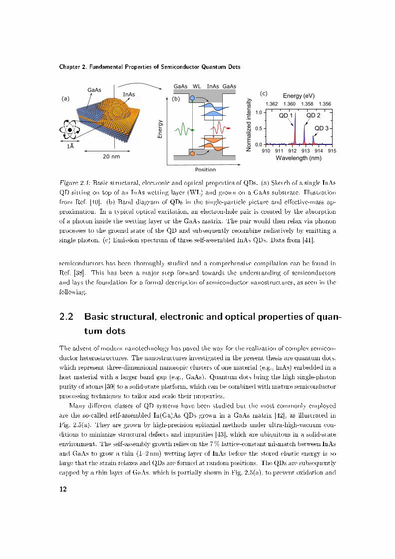
Figure 2.4: Basic structural, electronic and optical properties of QDs. (a) Sketch of a single InAs
QD sitting on top of an InAs wetting layer (WL) and grown on a GaAs substrate. Illustration
from Ref. [40]. (b) Band diagram of QDs in the single-particle picture and eective-mass ap-
proximation. In a typical optical excitation, an electron-hole pair is created by the absorption
of a photon inside the wetting layer or the GaAs matrix. The pair would then relax via phonon
processes to the ground state of the QD and subsequently recombine radiatively by emitting a
single photon. (c) Emission spectrum of three self-assembled InAs QDs. Data from [41].
semiconductors has been thoroughly studied and a comprehensive compilation can be found in
Ref. [38]. This has been a major step forward towards the understanding of semiconductors
and lays the foundation for a formal description of semiconductor nanostructures, as seen in the
following.
2.2 Basic structural, electronic and optical properties of quan-
tum dots
The advent of modern nanotechnology has paved the way for the realization of complex semicon-
ductor heterostructures. The nanostructures investigated in the present thesis are quantum dots,
which represent three-dimensional nanosopic clusters of one material (e.g., InAs) embedded in a
host material with a larger band gap (e.g., GaAs). Quantum dots bring the high single-photon
purity of atoms [39] to a solid-state platform, which can be combined with mature semiconductor
processing techniques to tailor and scale their properties.
Many dierent classes of QD systems have been studied but the most commonly employed
are the so-called self-assembled In(Ga)As QDs grown in a GaAs matrix [42], as illustrated in
Fig. 2.5(a). They are grown by high-precision epitaxial methods under ultra-high-vacuum con-
ditions to minimize structural defects and impurities [43], which are ubiquitous in a solid-state
environment. The self-assembly growth relies on the 7 % lattice-constant mismatch between InAs
and GaAs to grow a thin (12 nm) wetting layer of InAs before the stored elastic energy is so
large that the strain relaxes and QDs are formed at random positions. The QDs are subsequently
capped by a thin layer of GaAs, which is partially shown in Fig. 2.5(a), to prevent oxidation and
12
Basic structural, electronic and optical properties of quantum dots
saturate the surface states. The size of QDs is in the few-nanometer range: a height of 35 nm
and an in-plane size of 1530 nm are usually found [44]. Due to quantum connement, quantized
states are formed in the QDs, see a sketch of the resulting band diagram in Fig. 2.5(b). We have
depicted one single valence band because in a QD only the heavy-hole band is relevant in optical
processes; a rigorous justication is given in the next section. Normally one or two quantized
states are formed in the conduction and valence bands before the continuum density of states of
the wetting layer sets in. If the surrounding material is excited optically, the created electrons
and holes can be captured by the QD. The quantized energy structure of the latter results in the
generation of a one-photon Fock state as depicted in Fig. 2.5(b). The fermionic nature of the
electron-hole pair results in strong Coulomb and exchange interactions, which, in turn, induce
an anharmonic electronic spectrum, thereby justifying the excellent single-photon purity of QDs
observed experimentally. The random self-assembled growth process results in QDs with various
sizes, shapes and material composition, which leads to a broad inhomogenous emission spectrum.
A typical example of a photo-luminescence spectrum is shown in Fig. 2.5(c), where each narrow
spectral feature corresponds to the emission of a single self-assembled QD.
Aside from self-assembled QDs, we extensively study two other QD systems in the present
thesis: interface-uctuation QDs [27] and droplet-epitaxy QDs [45]. Despite being grown with
dierent techniques, all these classes of QDs share most of the electronic and optical properties
described above. In the following we learn how to describe QDs using the concepts developed
for semiconductors, which are presented in Sec. 2.1.
2.2.1 Electronic models of quantum dots. Eective-mass theory
One of the most important properties of semiconductors, the translational symmetry induced by
the periodicity of the crystal lattice, does not hold for nanostructures. Consequently, the Bloch
theorem is no longer valid and cannot be used to describe the QD wavefunctions. A typical
semiconductor QD has somewhere between 10 to 100 thousand atoms, which constitutes a huge
multi-body system and developing electronic-structure methods is therefore an extremely chal-
lenging task. The most accurate theoretical models are the so-called ab-initio approaches using
concepts from density functional theory [46], where each atom is described individually within
a complete atomistic framework. Such methods have proven exceedingly useful for describing
molecules [47] and periodic systems of up to several hundred atoms [48] but are computation-
ally infeasible for larger structures. They do, however, provide reliable parameters for the more
practical semi-empirical methods, which are described in the following.
The bandstructure models developed so far for QDs rely on empirical parameters, which
quantify certain properties of the complicated crystal potential (e.g., the eective mass). There
are two classes of commonly employed models: atomistic theories, such as the empirical pseu-
dopotential theory [49], which simulate the contribution of every single atom comprising the QD,
and continuum approaches, such as the multiband k · p theory [37], which discard the QD atom-
istic nature and consider only the macroscopic potential. Atomistic models successfully address
the structure and symmetry of the mesoscopic QD potential as well as the underlying crystal
13

Chapter 2. Fundamental Properties of Semiconductor Quantum Dots
symmetry but suer from a limited generality and a high computational eort approaching ab-
initio methods [50]. The most feasible and mature electronic-structure models are the continuum
approaches, where the entire atomistic nature is merged into a couple of empirical parameters,
and only a "macroscopic" Schrödinger equation needs to be solved treating the mesoscopic po-
tential of the QD. An excellent example constitutes the 8 × 8 k · p theory [51], where the QD
potential and strain couple the 8 relevant bands (4 bands with a two-fold spin degeneracy, see
Fig. 2.3) and yield a system of 8 coupled dierential equations, which are solved on a modern
computer with relative ease.
The most commonly employed continuum theory is the envelope function theory or k · ptheory, which has been developed by Bastard [52] and uses the periodic Bloch functions uΓ(r)
as a complete and orthogonal set to expand the QD wavefunction Ψ(r) [53]
Ψ(r) =∑n
ψn(r)un,Γ(r), (2.14)
where the index n runs over all the bands in the semiconductor and ψn(r) are the expansion
coecients, also called slowly varying envelopes. Since there is an innite number of bands in
the solid, the sum has to be truncated in practice. There are 4 relevant bands governing the
optical properties of III-V semiconductors as explained in Sec. 2.1. As a consequence, three main
approaches are used to truncate the sum in Eq. (2.14), namely in a 8× 8 (all the four bands are
coupled), 6× 6 (the three valence bands) and 4× 4 band (the heavy- and light-holes) approach.
For instance, the 6 × 6 k · p theory yields solutions for the valence band, while the conduction
band is treated separately in an eective-mass fashion, as explained in the following paragraph.
The k · p theory has had remarkable success in modeling quantum wells. One shortcoming of the
Ansatz of Eq. (2.14) is that the expansion is performed over a set of functions that is complete and
orthogonal in bulk but not in the particular nanostructure. A rst-principles theory developed
by Burt [54] and Foreman [55] addresses this issue but has been largely ignored because it shows
little discrepancy with the formalism developed by Bastard.
A particular case of k · p theory is the eective-mass approximation that will be extensively
used in this work. We rst present the theory before discussing its physical justication. The
theory assumes that the bands, which are exact solutions in bulk, interact little with one an-
other so that the eigenstates of the nanostructure retain their bulk periodicity. Formally, this
corresponds to one single term in Eq. (2.14), so that a quantized eigenstate in every band can
be written as
Ψj(r) = ψj(r)uj,Γ(r), (2.15)
where j = e,hh, lh, so belongs to either of the four bands. The time-dependent wavefunction
of this eigenstate, Ψj(r, t) = Ψj(r)e−i(Ej/~)t, is dierentiated with respect to time and, using the
parabolic dispersion relation at the Γ point in Eq. (2.11), yields a Schrödinger-type equation [31],
whose time-independent part reads
Ejψj(r) = − ~2
2meff,j∆ψj(r) + Vj(r)ψj(r), (2.16)
14

Basic structural, electronic and optical properties of quantum dots
Energy
Position
Eff-massapprox.
CB
VB
Figure 2.5: Physical interpretation of the eective-mass approximation. The complicated poten-
tial energy of the crystal (left) is merged into an eective-mass parameter (right).
where we have assumed that the eective mass is isotropic, which is a good approximation for III-
V semiconductors. The remarkable aspect about this eective-mass Schrödinger equation is that
the complicated unit-cell potential prole is merged into the eective-mass meff , a parameter
that can be accurately inferred from experiments. The potential energy V (r) now contains
only the smooth mesoscopic potential of the QD, as illustrated in Fig. 2.5. This particle-in-
a-box problem can be solved either analytically or numerically using the standard techniques
of quantum mechanics, which massively simplies the problem. There is need for one more
justication. In Eq. (2.16) V depends on r, which contradicts the single-electron approximation
by destroying the periodicity of the potential. However, if the potential is a smooth spatial
function, i.e., if its changes are small compared to the kinetic energy term over the scale of a
unit cell and over 2π |k|, then the material is called locally crystalline, and the eective-mass
approximation holds [31].
Even though QDs are complex three-dimensional structures, the eective-mass approximation
describes their properties remarkably well. This is because the rst valence-band eigenstate
is heavy-hole like with a negligible light-hole component for most QD systems. This can be
understood qualitatively as follows. The QDs that are presently studied have a small aspect
ratio, i.e., a height that is much smaller than the in-plane extension [44, 56, 57]. It turns out
that in the limit of vanishing in-plane connement, which is equivalent to a quantum well, the
heavy-hole band decouples from the light-hole band at the Γ point and is energetically closest
to the conduction band [58]. The splitting is of the order of 10 meV, which is suciently large
to confer a heavy-hole character to the rst quantized hole state of the quantum well. The
presence of a nite but small in-plane connement, as in the case of QDs with small aspect ratio,
15

Chapter 2. Fundamental Properties of Semiconductor Quantum Dots
induces a small light-hole contribution of less than 10 % and can be neglected for most practical
purposes [51, 59]. In this regard it is important to note that the eective-mass approximation is
only justied for QDs with small aspect ratio; other shapes may result in signicant heavy- and
light-hole mixing, and their electronic and optical properties would be altered. For instance, in
a spherical QD the heavy- and light-hole eigenstates remain degenerate because a sphere has a
higher symmetry than any crystal [60].
In addition to the aforementioned arguments, the eective-mass approximation is the most
widely employed QD theory due to its simplicity and intuitive nature. More complicated theories
have had a weak connection to experimental studies despite signicant theoretical eort. The
reason resides in the complexity of QDs, where optical spectroscopy is often incompatible with
studies of the exact geometry and material composition of QDs. In the present thesis we are
therefore employing the two-band eective-mass theory to describe the electronic properties of
QDs: we consider only the electron and the heavy-hole bands. There are QD systems, such as
self-assembled QDs, in which not only quantum connement but also strain plays an important
role in the electronic structure, as explained in the following.
2.2.2 Strain
There are three semiconductor systems investigated in the present thesis: Al(Ga)As, GaAs
and In(Ga)As. It so happens that the former two have the same lattice constant [38] and
the properties of the corresponding QDs are only governed by quantum connement. InAs
has, however, a 7 % larger lattice constant and, if grown on GaAs, the atoms are imposed to
accommodate to the lattice structure of the substrate, see the compressive-strain situation in
Fig. 2.6. Consequently, the atom i shifts from the equilibrium position ri to the non-equilibrium
position r′i, and the displacement vector u quanties this shift
u(ri) = r′i − ri. (2.17)
Since the atoms are away from equilibrium, internal forces tend to restore the equilibrium and
there is a certain elastic energy density E = E[u(r)] stored inside the QD. E is normally of the
order of tenths to hundredths of meV/nm3, i.e., of the same order as the quantization energy in
QDs, which is why strain plays an important role in the electronic structure of strained QDs.
The energy density E contains a dilatation component Es, which alters the band gap by
changing the volume of the unit cell without modifying the symmetry, and a distortion component
Ed, which lifts degeneracies in the valence band by lowering the symmetry of the unit cell. The
main inuence of compressive strain is to lower the light-hole band with respect to the heavy-
hole band, as illustrated in Fig. 2.7. As a consequence, in self-assembled QDs both quantum
connement and strain confer a negligible role to the light-hole band, thereby justifying the
eective-mass theory once again. It is worth mentioning the recent breakthrough of Huo et
al. [61], which managed to apply tensile strain to a QD (see Fig. 2.6) and to create a light-hole
ground state.
In a QD, the energy density E varies from unit cell to unit cell and, therefore, the band
structure is position-dependent as depicted in Fig. 2.8. In general, the distribution of strain
16

Basic structural, electronic and optical properties of quantum dots
Material 2Compressive strain
SubstrateFStrain
Material 1Tensile strain
z
Figure 2.6: Illustration of compressive and tensile strain.
k
E E
k
EgE'g
e
lhhh
CompressiveStrain e
hh
lh
Figure 2.7: Qualitative visualization of the inuence of compressive strain on the band structure
of a semiconductor.
17

Chapter 2. Fundamental Properties of Semiconductor Quantum Dots
x
Eg
x
E
E'g
E
CompressiveStrain
e
hh+lh hh
lh
e
Figure 2.8: Qualitative visualization of the inuence of compressive strain on the band diagram
of a QD.
within a QD can be calculated with continuum as well as atomistic approaches [62]. Continuum
models are fully compatible with the eective-mass theory because they employ the continuum
elasticity theory [63], where the QD is treated as a continuous mesoscopic system and its atomistic
nature is discarded. The contribution of strain is simply included as a separate potential-energy
term in Eq. (2.16), i.e., V (r) = Vconfinement(r)+Vstrain(r), and is calculated by solving the central
equation of continuum elasticity theory Navier's equation
∇ ·(←→C ∇u
)= 0, (2.18)
where←→C is the elastic stiness tensor and is a material parameter, which is well documented for
III-V semiconductors. A thorough introduction to continuum elasticity theory can be found in
Ref. [63] and its application to QDs in Ref. [58]. The predictive power of such theories is, however,
limited because the strain distribution depends on many parameters like material composition,
amount of crystalline defects, which vary from QD to QD and are generally unknown. The
inuence of strain can be calculated more exactly for quantum wells, where the clean crystalline
growth provides a well-dened physical problem.
2.2.3 Excitons. Weak- and strong-connement regimes
All the results we have arrived at so far are a consequence of the single-electron Schrödinger
equation, which is able to explain a remarkably large class of eects in crystals as well as in
nanostructures. In photonics, the central physical process is the absorption and emission of
light, which is normally triggered by the creation or recombination of an electron-hole pair. While
electrons and holes can be described individually within the single-electron approximation, they
can also interact with one another because they possess charge and half-integer spin. In QDs,
the interaction between electrons and holes is further enhanced with respect to bulk because
they are squeezed together in a small region of space of a few nanometers. This electron-hole
bound state constitutes a fundamental quasi-particle, the exciton, which governs the optical
18

Basic structural, electronic and optical properties of quantum dots
properties of a large class of semiconductor structures including QDs. Being a two-body system,
the description of the exciton goes beyond the single-electron approximation but is very similar
to the formalism we have presented so far, if the single-particle wavefunction Ψe/h is replaced
by the exciton wavefunction ΨX(re, rh). In a QD, ΨX can be expanded in the single-particle
electron and hole wavefunctions:
ΨX(re, rh) =∑n,m
Cn,mΨn(re)Ψm(rh), (2.19)
where Ψn corresponds to the n-th eigenstate of the QD. In the eective-mass approximation,
Ψn(r) = uΓ(r)ψn(r), where uΓ(r) is the periodic Bloch function evaluated at k = 0 and ψn(r)
the slowly varying envelope subject to the single-particle eective-mass Schrödinger equation.
In the following we drop the index Γ in the Bloch function for simplicity. Equation (2.19) can
therefore be written as
ΨX(re, rh) = ue(re)uh(rh)∑n,m
Cn,mψe,n(re)ψh,m(rh) = ue(re)uh(rh)ψX(re, rh), (2.20)
where χ(re, rh) is the slowly varying envelope of the exciton subject to the two-body eective-
mass Schrödinger equation(p2e
2me+
p2h
2mh+ Ve(re) + Vh(rh)− e2
4πε0εr |re − rh|
)ψX(re, rh) = EψX(re, rh). (2.21)
Here, εr is the background dielectric constant and E the eigenenergy of the exciton. In bulk, the
attraction between the electron and the hole results in a spatial separation between them known
as the exciton Bohr radius a0. Since the Coulomb energy EC scales inversely with the QD size
EC ∝ L−1, the Coulomb and exchange interactions in a QD are enhanced compared to bulk.
These processes confer a non-trivial ne structure to QDs, as explained in the next section.
Despite the enhanced Coulomb processes, the spatial motion and distribution of the exciton is
not only determined by Coulomb connement but also by quantum connement. It is well-known
from quantum-mechanics textbooks that the quantum-connement energy scales as † L−2 [31].
As a consequence, the exciton motion can be found in two regimes:
(i) The strong-connement regime, in which the QD size L is smaller than the exciton Bohr
radius a0 [60] and quantum connement dominates Coulomb connement. The latter can then be
treated as a vanishingly small perturbation and, in the rst approximation, neglected completely.
As a consequence, the electron and hole move independently of each other as non-interacting
particles and the exciton slowly varying envelope χ can be written as a product of the individual
electron and hole wavefunctions, i.e.,
ψX(re, rh) = ψe(re)ψh(rh). (2.22)
The single-particle wavefunctions ψe,h(r) can then be computed individually with the single-
particle eective-mass Schrödinger equation, thereby substantially simplifying the problem. Most
†More precisely, the connement energy scales as L−2 only for a potential well with innite barriers [31]. In
practice it scales as L−n with n ∈ (1; 2).
19

Chapter 2. Fundamental Properties of Semiconductor Quantum Dots
of the semiconductor QDs studied so far belong to the strong-connement regime and, despite
being a complex multi-body system, can be modelled within the single-particle approximation
remarkably well.
(ii) The weak-connement regime, in which L a0 and the electron-hole motion is strongly
correlated with a negligible role from the QD boundary. Here, Eq. (2.21) cannot be simplied
further and has to be solved as a two-body problem. Achieving this regime has been a long-
sought goal in quantum photonics because such QDs couple giantly to light, as is experimentally
demonstrated in Chapter 3.
Excitonic eects have a prominent role in determining the QD energy structure because they
couple the bare single-particle eigenstates, as seen in the following.
2.2.4 Heavy-hole excitons
An electron in the conduction band and a heavy hole in the valence band constitute the funda-
mental quasi-particle studied throughout the present thesis: the heavy-hole exciton. Combining
the electron contribution with a spin of ±1/2 with the heavy-hole contribution with a projected
angular momentum of ±3/2, see Eq. (2.12), yields four possible excitonic congurations: two
optically bright excitons with jz = ±1 and two optically dark with jz = ±2. Their optical
brightness can be checked explicitly by evaluating the dipole moment
µ =e
m0〈0 |p|ΨX〉 , (2.23)
where |0〉 denotes the vacuum state. The underlying fermionic nature of the excitons leads to an
exchange-type interaction between the the electron and hole, which couples and splits these four
bare excitonic eigenstates. Understanding their energy structure in an important prerequisite
for performing and interpreting spectroscopic analyses on QDs, as explained in Sec. 2.5. In this
section we present the formalism that can be used to provide such an understanding.
Using standard semiconductor-physics textbooks [64], it can be shown that the energy of the
exchange interaction is proportional to [65]
Eexchange ∝∫ ∫
dr1dr2Ψ∗X(re = r1, rh = r2)1
|r1 − r2|ΨX(re = r2, rh = r1). (2.24)
The integration is normally divided in two parts leading to a short-range contribution where
the electron and hole are in the same unit cell, and a long-range interaction where the particles
are in dierent cells. The latter has little eect on the energy structure [65] and we therefore
discuss only the former. The main role of the short-range interaction is to split the bright and
dark states in energy. This can be understood by using the short-range interaction Hamiltonian,
which is derived using the theory of invariants and contains an electron with spin se and a hole
with spin jh [66]
Hshort = −∑
i=x,y,z
(aijh,ise,i + bij
3h,ise,i
), (2.25)
where a and b are QD parameters. Evaluating the operators s and j on the projected angular
momentum bases (|+1〉 , |−1〉 , |+2〉 , |−2〉) is discussed in detail in Ref. [67] and is outlined in
20

Basic structural, electronic and optical properties of quantum dots
Appendix A. The resulting matrix representation of the Hamiltonian reads
Hheavy-hole =1
2
+δ0 +δ1 0 0
+δ1 +δ0 0 0
0 0 −δ0 +δ2
0 0 +δ2 −δ0
, (2.26)
where δ0 = 1.5(az + 2.25bz), δ1 = 0.75(bx − by), and δ2 = 0.75(bx + by). Since the matrix is
block diagonal, bright and dark excitons do not mix with each other but are split by δ0. Bright
excitons, however, mix with each other and are split by δ1, as are dark excitons by δ2, and the
new eigenstates are symmetric and antisymmetric combinations of the bare states, i.e.,
|ΨX1〉 =1√2
(|−1〉+ |1〉) ,
|ΨX2〉 =1√2
(|−1〉 − |1〉) ,
|ΨX3〉 =1√2
(|−2〉+ |2〉) ,
|ΨX4〉 =1√2
(|−2〉 − |2〉) ,
(2.27)
where |b〉 and |d〉 denote bright and dark states, respectively. The transition dipole moment of
the dressed states can be computed with the help of Eqs. (2.12) and (2.23) yielding
µX1 = −iΠey,
µX2 = Πex,
µX3 = µX4 = 0,
(2.28)
where Π = 〈ux |px|ue〉 and we have omitted the slowly varying envelopes for simplicity since
they do not carry any information about polarization. The two bright states are orthogonally
polarized along the x = [1, 1, 0] and y = [1,−1, 0] crystallographic directions, respectively.
The splitting between the two bright states is of the order of tens of µeV [68] and is mostly
determined by the QD asymmetry. For in-plane symmetric QDs, bx = by and the two bright
eigenstates are degenerate. Such a scenario is hardly ever encountered in practice because it
can be shown with more exact atomistic models [68] that even perfectly symmetric QDs have a
lower crystallographic symmetry leading to the eigenstates of Eq. (2.27). The two parameters bx
and by depend on the QD wavefunctions and can be tuned by external elds, which change the
distribution of the wavefunctions within the QD [69]. Bright excitons are higher in energy than
dark excitons by several hundred µeV [68] and the corresponding energy structure is illustrated
in Fig. 2.9. These properties of the heavy-hole exciton will be used throughout the present thesis,
both in spectroscopic analyses and in theoretical calculations.
2.2.5 Light-hole excitons
The light-hole exciton is a fundamental quasi-particle formed by an electron in the conduction
band and a light hole in the valence band. Despite the fact that most of the QD studies have
21

Chapter 2. Fundamental Properties of Semiconductor Quantum Dots
Energy structure Dipole moment
Figure 2.9: Energy structure and the corresponding orientation of the dipole moment of a heavy-
hole exciton.
dealt with heavy-hole excitons so far, light-hole excitons conned in single QDs are becoming
experimentally accessible [61] and provide a new platform for the exploration of QDs in quantum
technologies. We therefore present their ne structure but note that this section is not required
for understanding the rest of the thesis.
The light-hole excitons contain a hole with j = 1/2 and an electron with s = 1/2, and form
4 possible congurations(|0jz=1/2,sz=−1/2〉 , |0jz=−1/2,sz=1/2〉 , |1〉 , |−1〉
)≡ (|0〉 , |0〉 , |1〉 , |−1〉).
It can be checked using Eq. (2.12) that, unlike heavy-hole excitons, all these bare states are
optically active. The Hamiltonian in Eq. (2.25) can be evaluated in this basis set with the help
of Appendix A yielding
Hlight−hole =1
2
+∆0 +∆1 0 0
+∆1 +∆0 0 0
0 0 −∆0 +∆2
0 0 +∆2 −∆0
, (2.29)
where ∆0 = 0.5(a3 + 0.125b3), ∆1 = −(a1 +a2 + 2.5b1 + 2.5b2) and ∆2 = (a2−a1) + 2.5(b2− b1).
The matrix is block diagonal and excitons with mj = 0 do not couple to excitons with |mj | = 1
but are split in energy by ∆0. Excitons with the same |mj | are coupled by ∆1 and ∆2, and the
dressed eigenstates constitute symmetric and antisymmetric superpositions of the bare states
|ΨX1〉 =1√2
(|0〉+ |0〉) ,
|ΨX2〉 =1√2
(|0〉 − |0〉) ,
|ΨX3〉 =1√2
(|−1〉+ |1〉) ,
|ΨX4〉 =1√2
(|−1〉 − |1〉) .
(2.30)
Despite being mathematically analogous, light-hole excitons have a dierent polarization spec-
22

Density of states of conned systems
Energy structure Dipole moment
Figure 2.10: Energy structure and the corresponding orientation of the dipole moment of a
light-hole exciton.
trum. The dipole moment of the 4 states is evaluated using Eq. (2.12) yielding
µX1 =2√3
Πez,
µX2 = 0,
µX3 = −i 1√3
Πey,
µX4 =1√3
Πex.
(2.31)
The light-hole excitons have electric dipoles oriented along all three Cartesian directions x, y and
z = [0, 0, 1]. The z-polarized exciton has a dipole moment twice larger than the other two bright
excitons, and is normally higher in energy by several hundred µeV [61] as shown schematically in
Fig. 2.10. The x- and y-polarized states inherit the properties of the bright heavy-hole excitons
but have a smaller dipole moment.
2.3 Density of states of conned systems
The density of electronic states (DES) is an important quantity that governs the process of
absorption and emission of light in semiconductor nanostructures. Quantum dots are often
grown on a wetting layer or a quantum well, which represents a combination of zero- and two-
dimensional systems. They therefore exhibit a non-trivial energy structure with a certain spectral
density of available states. In the following we derive the DES of an arbitrary n-dimensional
system and then analyze particular cases.
The DES is dened as the number of available electronic states per unit volume and energy.
According to Fermi's Golden Rule, which is discussed in Sec. 2.5, the absorption of light is
directly proportional to DES. We consider one single band with an isotropic eective mass meff
23

Chapter 2. Fundamental Properties of Semiconductor Quantum Dots
but the extension to multiple bands is done straightforwardly in an additive fashion
E =~2k2
2meff. (2.32)
Since the reciprocal lattice is discrete, the wavevector of the electron can take only discrete
values separated equidistantly by 2πL , where L is the length of the one dimensional system. In n
dimensions the elementary volume of the reciprocal lattice Vk,n equals
δVk,n =(2π)n
Vn, (2.33)
where Vn is the volume of the structure. The number of states gn(k) normalized to the volume
of both the real and reciprocal lattices is just the inverse of δVk,n divided by Vn, i.e., gn(k) =
1/(δVk,nVn)
gn(k) =1
(2π)n. (2.34)
The quantity gn(k) is the so-called density of states in k-space and is a constant. To relate it to
the relevant DES in energy, the dispersion relation between the k and energy spaces needs to be
used, see Eq. (2.32), which implies that the iso-energy surface is an n-dimensional sphere. We take
into account spin degeneracy (i.e., a factor of 2) and that the surface of a n-dimensional sphere
equals 2πn/2kn−1
Γ(n/2) , where Γ denotes the Gamma-function. Hence, the DES in energy multiplied
by an innitesimal energy interval dE must be equal to the DES in k-space multiplied by an
innitesimal volume in k-space dnk, i.e.,
gn(E)dE = 2gn(k)dnk = 21
(2π)n2π
n2 kn−1
Γ(n2
) (dk
dE
)dE. (2.35)
By carrying out the calculation one arrives at
gn(E) =2
Γ(n2
) (meff
2π~2
)n2
(E − E0)n2−1. (2.36)
The DES in 0, 1, 2 and 3 dimensions is evaluated as
g0(E) = 2δ(E − E0)
g1(E) =
√2meff
π~1√
E − E0
g2(E) =meff
π~2
g3(E) =
√2m
3/2eff
π2~3
√E − E0.
(2.37)
Figure 2.11 visualizes the DES in dierent dimensions. As the dimensionality of the system
is lowered, the DES becomes more conned in energy. In a zero-dimensional system, which
corresponds to a QD, the DES is a sequence of delta functions, thereby justifying the spectrally
narrow emission lines from QDs in Fig. 2.3(c). The DES can be measured eciently in absorption
measurements. An excellent example is shown in Ref. [70], where the stepwise DES of a quantum
well is observed experimentally and modelled theoretically remarkably well. The advantage of
the spectrally narrow DES in QDs is that the oscillator strength of an entire band is merged into
a single narrow line, which induces a large spectral interaction between QDs and light [71].
24

The electromagnetic quantum-vacuum eld
DES
Energy
n=2n=3 n=1 n=0
Figure 2.11: Illustration of the DES in 0, 1, 2 and 3 dimensions.
2.4 The electromagnetic quantum-vacuum eld
Spontaneous emission is the central physical process studied in the present thesis. An excited
emitter such as a QD may interact with the electromagnetic quantum-vacuum eld and sponta-
neously emit a photon. While the properties of the quantum emitter have been investigated in
detail in the previous section, here we present the physical properties of light, which comprises
electric and magnetic elds that oscillate in time and space. We rst describe their classical prop-
erties before generalizing them into a quantum-mechanical framework. Maxwell's equations are
the fundamental relations that govern the behavior and propagation of electromagnetic elds [72]
∇×E(r, t) = −∂B(r, t)
∂t,
∇ ·B(r, t) = 0,
∇×H(r, t) =∂D(r, t)
∂t+ j(r, t),
∇ ·D(r, t) = ρ(r, t),
(2.38)
where E, B, D, H denote the electric eld, magnetic induction, electric displacement and mag-
netic eld, respectively, and j and ρ the current and charge densities, respectively. These identi-
ties are complemented by the constitutive equations relating D and B to E and H through the
electric and magnetic properties of the material, which we assume to be isotropic
D(r, t) = ε0ε(r)E(r, t),
B(r, t) = µ0µ(r)H(r, t),(2.39)
where ε0 and µ0 (ε and µ) the vacuum (relative) electric permittivity and magnetic permeability,
respectively. We henceforth assume non-magnetic media at optical frequencies and set µ(r) = 1.
The electromagnetic eld generated by a quantum emitter propagates according to the rules
established by Maxwell's equations. Combining the latter with the constitutive relations yields
25

Chapter 2. Fundamental Properties of Semiconductor Quantum Dots
the fundamental equation governing the propagation of the electromagnetic eld in space and
time the wave equation
∇×∇×E(r, t) +ε(r)
c20
∂2E(r, t)
∂t2= −µ0j(r, t), (2.40)
subject to the condition ∇ × E = 0. Here, c0 = (ε0µ0)−1/2 is the vacuum speed of light and
we have assumed charge-free environments ρ = 0. An optically linear medium does not couple
dierent frequency components and the elds can be expanded in time-harmonic modes via
E(r, t) = E(r)e−iωt and similarly for j. The spatial prole E(r) satises the Helmholtz equation,
which is obtained by plugging the modes into the wave equation in Eq. (2.40)
∇×∇×E(r)− ε(r)k20E(r) = iωµ0j(r), (2.41)
where k0 = ω/c0 is the wavevector of light in vacuum. This equation contains a potentially
complex spatial distribution of a source current on the right-hand side, which generates the eld
prole from the left-hand side. A powerful method of solving such an inhomogeneous dierential
equation is to use the Green tensor of the system←→G (r, r′), which is dened by the electric eld
at the eld point r generated by an electric dipole located at r′ [72]. The Green tensor satises
the Helmholtz equation similarly to the electric eld E(r) but with a point-like source replacing
the complex current distribution j(r)
∇×∇×←→G (r, r′)− ε(r)k2
0
←→G (r, r′) =
←→I δ(r− r′), (2.42)
where←→I is the unit tensor. The Green function is the impulse response of the system and,
according to the convolution theorem, can be used to calculate the radiation E(r) of an arbitrary
current distribution j(r) via
E(r) = iωµ0
∫dr′←→G (r, r′)j(r′). (2.43)
The Green tensor is solely a property of the electromagnetic environment and is determined
by the distribution of the permittivity ε(r). The physical meaning of←→G can be grasped by
considering a radiating point dipole at r0, i.e., j(r) = −iωpδ(r − r0), where p is the electric
dipole moment
E(r) = ω2µ0←→G (r, r0)p. (2.44)
We can interpret the Green tensor as a propagator for the electric eld from r0 to r in an
environment determined by ε(r).
The concept of the Green function will be extensively used in the present thesis when studying
the light-matter interaction. Closed-form expressions for the Green tensor exist only for a few
specic environments, such as a stratied medium [73]. It is often convenient to separate←→G (r, r′)
into a homogeneous-medium component←→GH(r, r′), which normally coincides with the medium
where the quantum emitter is located, and a scattering component←→GS(r, r′), which provides the
response of the inhomogeneous character of the environment. The homogeneous solution can be
26
Fundamental light-matter interaction with quantum dots
expressed in a closed form via [74]
←→GH(r, r′) =
(←→I +
∇∇k2H
)eikHR
4πR, (2.45)
where kH = k0√εH is the wavevector in the background medium with a relative permittivity
εH , and R = |R| = |r− r′| is the relative distance.It is well known from classical electrodynamics that the electric E and magnetic B elds can
be recast in terms of the scalar φ and vector A potentials. From ∇ ·B = 0 it follows that the
magnetic induction can be written as the curl of the vector potential because ∇ · (∇×) ≡ 0.
Then it follows from Maxwell's equations that
B = ∇×A,
E = −∂A
∂t−∇φ.
(2.46)
Even though these relations uniquely determine E and B, they are not sucient to specify the
potentials uniquely. This is why a choice of gauge needs to be adopted where a further constraint
xes the uniqueness of A and φ. It is often preferred to deal with the potentials rather than the
physically more meaningful electric and magnetic elds, as is shown in the next section.
The spontaneous-emission process is triggered by the ground state of the electromagnetic eld,
formally denoted as the electromagnetic vacuum eld. In a quantum-mechanical picture, the
vacuum eld has a nite energy of ~ω/2 and can be explained by quantizing the electromagnetic
eld [75]. The electric eld becomes an operator
E(r) = i∑l
√~ωl2ε0
[alfl(r) + a†l f
∗l (r)
], (2.47)
where a†l and al are the creation and annihilation operators of a photon in the normal eld mode
fl(r), which satises the Helmholtz equation and obeys the normalization condition∫drε(r)f∗m(r) · fn(r) = δmn. (2.48)
The normal modes fi(r) are eigensolutions of the Helmholtz equation and any eld E(r) can be
expanded into them. The magnetic-eld operator can be recast from Eq. (2.47) using Maxwell's
equations. The quantization procedure confers a non-zero variance to the ground (or vacuum)
state of the electromagnetic eld |0〉, which is identically zero in the classical description. Such a
vacuum state can be depicted as virtual photons that exist in brief moments of time, as allowed
by the uncertainty principle of quantum mechanics. Spontaneous emission is triggered by the
interaction of an excited emitter with these virtual photons belonging to the vacuum state |0〉resulting in an emitted photon in the mode l, i.e., |1l〉, as shown in the following section.
2.5 Fundamental light-matter interaction with quantum dots
The interaction between light and matter is an ubiquitous process in nature and lies at the
heart of modern light sources and detectors, such as light-emitting diodes, lasers, photodiodes
27

Chapter 2. Fundamental Properties of Semiconductor Quantum Dots
and solar cells. Eciently interfacing solid-state quantum emitters with light plays a paramount
role in quantum-information science and is the subject of intense fundamental research in cavity
quantum electrodynamics [22]. In the present section we lay the fundamental as well as the
experimentally relevant aspects describing the interaction between QDs and light, which represent
the starting point for the research carrier out in this work.
2.5.1 Spontaneous emission
The process of photon emission governs the conversion of a stationary qubit to a ying qubit and
its understanding is of immense signicance for the realization of ecient light-matter interfaces.
The interaction between an exciton in a QD with the electromagnetic vacuum eld is the central
process studied in the present thesis. An important aspect of this process is the temporal
dynamics of the exciton-to-photon conversion, which is governed by the light-matter interaction
strength. The latter was considered to be solely an intrinsic property of the emitter before the
work of Purcell in 1946 [5], which showed that the spatial density of the optical modes can
tailor this interaction. Purcell found that the spontaneous-emission rate of an emitter in a cavity
was increased by a factor of FP = 3Qλ2/4π2V , where Q and V are the quality factor and
the mode volume of the cavity, respectively, and λ is the wavelength of light. This prediction
was experimentally veried by Drexhage in 1970 [76], where he found that the spontaneous-
emission rate can be both enhanced and suppressed when the distance between an emitter and
a metal surface is varied. Nowadays, modern fabrication techniques enable accurate tailoring
of the nanophotonic environment surrounding QDs, which in turn allows to carefully optimize
the light-matter coupling strength. Fundamental as well as applied studies of QDs in photonic-
crystal cavities [77] and waveguides [21], micropillar cavities [20] and nanowires [78] constitute a
few out of many hot research directions that are followed at the moment.
The QD-light interaction can be found in two fundamental regimes, namely the strong- and
weak-coupling regimes, which are distinguished based on the coupling strength g [72]
g =
√~ω
2ε0V
µ
~, (2.49)
where µ is the QD dipole matrix element from the excited to the ground state. For g Γrad,
where Γrad is the spontaneous-emission rate into the cavity, the interaction is in the strong-
coupling regime, and light and matter degrees of freedom become entangled. This leads to a
non-Markovian time decay of the emitter because the emitted photon is likely to be re-absorbed
a number of times before it leaks out of the cavity. These so-called vacuum Rabi oscillations
were experimentally demonstrated nearly 20 years ago at microwave frequencies [79], which has
been followed by a plethora of similar studies in other systems including QDs in solid-state
cavities [80].
The regime in which the cavity enhances the density of optical states with a subsequent
Markovian dynamics is the weak-coupling regime, i.e., g Γrad, which is the most widely
studied type of light-matter interaction and is main focus of the present thesis. In this regime,
the exciton population of the QD decays exponentially with the rate Γrad subject to Fermi's
28

Fundamental light-matter interaction with quantum dots
Golden Rule [31]
Γrad(ω) =2π
~2
∑f
∣∣∣⟨f ∣∣∣Hint
∣∣∣ i⟩∣∣∣2 δ(ω − ωif ), (2.50)
where Hint is the light-matter interaction Hamiltonian triggering a transition from the initial |i〉to the nal |f〉 state. In this work we consider the minimal coupling interaction Hamiltonian [81]
between a particle with charge e and mass m0, and the eld described by the vector A and scalar
φ potentials
Hint = − e
2m0
(p · A + A · p− eA · A
). (2.51)
Another commonly used interaction Hamiltonian is the multipolar formalism, where the Hamil-
tonian is expressed in terms of the physically meaningful electric E and magnetic B elds. It
can be shown [81] that the two Hamiltonians give the same result for processes subject to energy
conservation such as spontaneous emission. In Chapter 5 we are showing this explicitly when
developing a multipolar theory of light-matter interaction with QDs.
The nonlinear term A · A can be neglected for the weak elds with low energies triggering
spontaneous emission at optical frequencies. We employ the generalized Coulomb gauge in which
the scalar potential vanishes φ = 0 [82]
∇ ·[ε(r)A(r)
]= 0, (2.52)
which renders the commutator [A, p] = ∇ · A, in general, dierent than zero. In this work
we consider spatial variations of the dielectric constant over length scales much smaller than
the QD spatial extent and we may treat ε(r) constant [82], thereby yielding for the interaction
Hamiltonian
Hint ' −e
m0A(r) · p. (2.53)
The vector-potential operator can be recast from Eq. (2.47) using Eq. (2.46)
A(r) =∑l
√~
2ε0ωl
[alfl(r) + a†l f
∗l (r)
]. (2.54)
We approximate the QD with a two-level system with the initial state |i〉 = |e〉 ⊗ |0〉, where |e〉denotes the excited electronic state and |0〉 the vacuum state of the electromagnetic eld, and
|f〉 = |g〉 ⊗ |1f 〉 the nal state with one excitation in the eld mode f and the emitter in the
ground state |g〉. We note that only the term containing a† yields a non-zero contribution to
Γrad and Eq. (2.50) can be written as
Γrad(ω) =πe2
ε0~m20
∑f
∣∣∣∣∣∑l
1√ωl〈g| f∗l (r) · p |e〉 〈1f | a†l |0〉
∣∣∣∣∣2
δ(ω − ωf ). (2.55)
The eld matrix element yields 〈1f | a†l |0〉 = δlf and we arrive at the important result
Γrad(ω) =πe2
ε0~m20
∑l
1
ωl|〈g| f∗l (r) · p |e〉|2 δ(ω − ωl), (2.56)
29

Chapter 2. Fundamental Properties of Semiconductor Quantum Dots
which is the starting point for the formalisms developed in the present thesis. The meaning of
the sum∑l is that the emitter can decay over the entire 4π solid angle at a xed frequency
ωl. This is the most general expression describing the decay rate of a two-level emitter in the
weak-coupling regime. The expression is beyond the textbook dipole approximation because the
distribution of the eld over the emitter is fully taken into account. While providing interesting
theoretical challenges, Γrad is also a physical observable and, thus, an experimentally accessible
quantity. Novel and exciting information about both the QD and the eld can be inferred from
comparing theory with experiment, as shown by the research in the present thesis.
2.5.2 The dipole approximation
The standard-textbook approach to evaluating Eq. (2.56) is to assume that the electromagnetic
eld varies slowly over the spatial extent of the QD fl(r) ≈ fl(r0), where r0 is the center of the
QD. The resulting dipole approximation is excellent for most quantum emitters because they
are much smaller than the wavelength of light. Under this assumption, Fermi's Golden Rule,
Eq. (2.56), reads
Γrad(ω) =π |µ|2
ε0~ep ·
[∑l
1
ωlf∗(r0)f(r0)δ(ω − ωl)
]· e∗p, (2.57)
where ep is the unit vector pointing along the direction of the dipole moment µ, which is given
by Eq. (2.23). It can be shown [72, 83] that the term in square brackets is proportional to the
imaginary part of the Green tensor evaluated at the origin
Im[←→G (r0, r0)
]=πc202
∑l
1
ωlf∗l (r0)fl(r0)δ(ω − ωl), (2.58)
which yields for the decay rate
Γrad(ω) =2µ0 |µ|2
~Im[ep ·←→G (r0, r0) · e∗p
]. (2.59)
In the dipole approximation, the light-matter interaction strength is governed by two fundamental
quantities: the dipole moment, which is an intrinsic property of the emitter, and the projected
imaginary part of the Green tensor, which is purely a property of the electromagnetic eld.
Tailoring the spontaneous-emission process can therefore be done either at the emitter level using
novel growth techniques of QDs or at the eld level by structuring the environment surrounding
the QDs.
It is often useful to recast the emitter and eld properties in terms of quantities with a more
intuitive physical meaning, namely the oscillator strength f and the local density of optical
states (LDOS) ρ(r0, ω, ep). The oscillator strength is a dimensionless quantity dened as the
ratio between the radiative rate of the QD in a homogeneous environment and the emission rate
of a classical harmonic oscillator, and is related to the dipole moment via
f =m0
e2~ω|µ|2 . (2.60)
30
Fundamental light-matter interaction with quantum dots
The oscillator strength of atoms is of the order of 1 and of QDs about 10 [84], which makes QDs
ecient light-matter interfaces. The LDOS is dened as the number of electromagnetic modes
per unit energy and volume that the emitter can decay into, and is related to the projected Green
tensor via
ρ(r0, ω, ep) =2ω
πc20Im[ep ·←→G (r0, r0) · e∗p
]. (2.61)
The LDOS can be both enhanced and suppressed with respect to a homogeneous medium, as
shown by Drexhage 40 years ago. Placing the emitter in the antinode of a cavity may substantially
enhance the LDOS and, thus, the light-matter coupling strength, whereas in a photonic band
gap the spontaneous-emission process would be strongly suppressed because there are no modes
the emitter can decay into.
In a homogeneous environment, Eq. (2.59) can be evaluated analytically by taking the limit
R→ 0 in the homogeneous part of the Green tensor in Eq. (5.46), which yields
Im[←→G (r0, r0)
]=
ωn
6πc0
←→I , (2.62)
where n = ε2 is the refractive index of the background medium. The LDOS scales linearly with
the wavevector of light kB because larger wavevectors correspond to an increased number of
propagating eld modes inside the medium. This yields the textbook expression for the decay
rate in a homogeneous medium
Γhomrad =
µ0ωn
3π~c0|µ|2 . (2.63)
Finally we note that only the imaginary part of the Green tensor contributes to the decay
rate because energy dissipation is described by the part of the response function, which is π/2
out of phase with the driving eld, as is known from linear response theory. The real part is
proportional to a self-energy term, also known as the Lamb shift, which shifts the frequency of
the QD exciton [85].
2.5.3 Decay dynamics of quantum dots
So far we have described the spontaneous-emission process of QDs as the recombination of
a two-level system. In reality, however, the level structure of QDs is more complicated, as
presented in Sec. 2.2: there are 4 excited states comprising 2 bright and 2 dark excitons. These
states are coupled by spin-ip processes because the constituent electron or hole may ip spin.
The complexity of the problem is further enhanced by the omnipresent nonradiative processes,
such as defect traps in the vicinity of the QD [86], which provide alternative pathways for
the recombination of the exciton. All in all, the experimentally measured decay dynamics of
QDs intertwines radiative, nonradiative and spin-ip process and is more complex than a single
decaying exponential. It is of high experimental signicance to extract all these rates from
measurement because they provide important information about the optical quality of QDs,
namely the oscillator strength, which is proportional to the radiative rate, and the quantum
eciency η, which quanties the probability that an exciton captured by the QD recombines
31

Chapter 2. Fundamental Properties of Semiconductor Quantum Dots
Figure 2.12: Level scheme describing the population transfer of the exciton in a QD, which has
a direct impact on the bright-exciton decay dynamics. The bright exciton |b〉 can decay either
radiatively (Γrad) or nonradiatively (Γnrad) and can interact with its dark counterpart |d〉 via thespin-ip rate (Γsf).
radiatively
η =Γhom
rad
Γhomrad + Γnrad
, (2.64)
where Γnrad is the nonradiative decay rate and Γhomrad denotes the radiative rate in a homogeneous
medium. In the following we present a method that can unambiguously extract these quantities
from optical measurements and that will be extensively used in the present work [57, 84].
The picture involving the 5 coupled QD levels (4 excited states and one ground state) can be
simplied by noting that spin-ip processes are strongly inhibited in QDs as compared to bulk
or quantum wells because the energy levels are quantized, which makes it dicult for charge
carriers to simultaneously ip spin and full energy conservation. We can therefore retain only
rst-order spin-ip processes and neglect double or higher-order processes. This leads to a picture
in which the coupling between bright-bright and dark-dark excitons is removed because it is a
second order process, i.e., it involves two spin-ip processes. As a consequence, only bright-dark
excitons are coupled by the spin-ip rate Γsf and the former ve-level picture is reduced to the
three-level scheme depicted in Fig. 2.12.
Bright excitons |b〉 may decay both radiatively with the rate Γrad or nonradiatively with
Γnrad. Additionally, bright excitons may ip spin and become dark with the rate Γsf . Dark
excitons |d〉 do not decay radiatively owing to optical selection rules presented in Sec. 2.2 but
they may decay nonradiatively with Γnrad and ip spin with Γsf . In the previous statements
we have implicitly carried out two further assumptions. First, the bright-dark and dark-bright
spin-ip rates are assumed to be the same because the spin-ip process is phonon mediated owing
to the energy-conservation requirement. As a consequence, the thermal energy kBT ≈ 1 meV
at a temperature of T = 10 K that the experiments in the present work are carried out at, is
much larger than the bright-dark energy splitting δ0 ≈ 100µeV. Second, the nonradiative rates
for bright and dark excitons are assumed to be the same due to their small energy splitting, as
demonstrated experimentally in Ref. [87].
The decay dynamics of the bright exciton are governed by the rate equations of the coupled
32
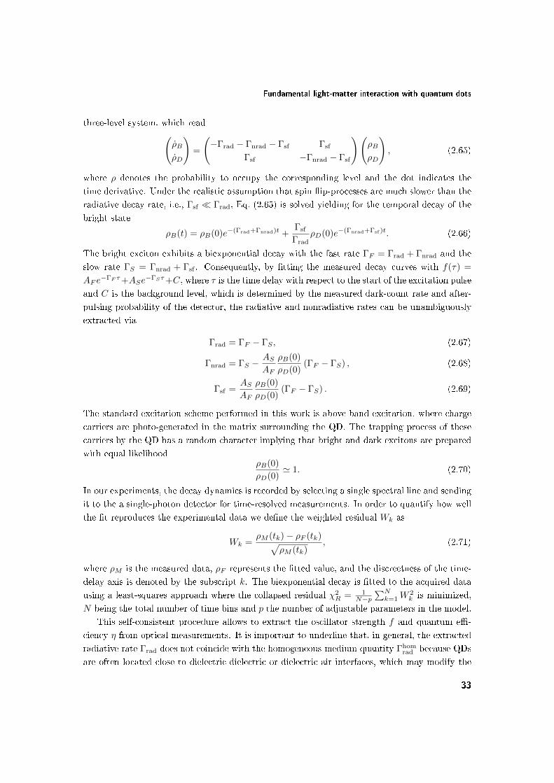
Fundamental light-matter interaction with quantum dots
three-level system, which read(ρB
ρD
)=
(−Γrad − Γnrad − Γsf Γsf
Γsf −Γnrad − Γsf
)(ρB
ρD
), (2.65)
where ρ denotes the probability to occupy the corresponding level and the dot indicates the
time derivative. Under the realistic assumption that spin ip-processes are much slower than the
radiative decay rate, i.e., Γsf Γrad, Eq. (2.65) is solved yielding for the temporal decay of the
bright state
ρB(t) = ρB(0)e−(Γrad+Γnrad)t +Γsf
ΓradρD(0)e−(Γnrad+Γsf )t. (2.66)
The bright exciton exhibits a biexponential decay with the fast rate ΓF = Γrad + Γnrad and the
slow rate ΓS = Γnrad + Γsf . Consequently, by tting the measured decay curves with f(τ) =
AF e−ΓF τ+ASe
−ΓSτ+C, where τ is the time delay with respect to the start of the excitation pulse
and C is the background level, which is determined by the measured dark-count rate and after-
pulsing probability of the detector, the radiative and nonradiative rates can be unambiguously
extracted via
Γrad = ΓF − ΓS , (2.67)
Γnrad = ΓS −ASAF
ρB(0)
ρD(0)(ΓF − ΓS) , (2.68)
Γsf =ASAF
ρB(0)
ρD(0)(ΓF − ΓS) . (2.69)
The standard excitation scheme performed in this work is above-band excitation, where charge
carriers are photo-generated in the matrix surrounding the QD. The trapping process of these
carriers by the QD has a random character implying that bright and dark excitons are prepared
with equal likelihoodρB(0)
ρD(0)' 1. (2.70)
In our experiments, the decay dynamics is recorded by selecting a single spectral line and sending
it to the a single-photon detector for time-resolved measurements. In order to quantify how well
the t reproduces the experimental data we dene the weighted residual Wk as
Wk =ρM (tk)− ρF (tk)√
ρM (tk), (2.71)
where ρM is the measured data, ρF represents the tted value, and the discreetness of the time-
delay axis is denoted by the subscript k. The biexponential decay is tted to the acquired data
using a least-squares approach where the collapsed residual χ2R = 1
N−p∑Nk=1W
2k is minimized,
N being the total number of time bins and p the number of adjustable parameters in the model.
This self-consistent procedure allows to extract the oscillator strength f and quantum e-
ciency η from optical measurements. It is important to underline that, in general, the extracted
radiative rate Γrad does not coincide with the homogeneous-medium quantity Γhomrad because QDs
are often located close to dielectric-dielectric or dielectric-air interfaces, which may modify the
33

Chapter 2. Fundamental Properties of Semiconductor Quantum Dots
projected LDOS at the QD position. It is therefore important to determine the LDOS contribu-
tion in every experiment to correctly evaluate the oscillator strength and quantum eciency.
In conclusion, we stress that spin ip is the key process making the aforementioned scheme
work. In the present thesis we study three dierent classes of QDs and we nd the biexponential
model to reproduce the decay dynamics of the bright exciton remarkably well.
2.6 Summary
In this chapter we have presented the important physical processes describing light-matter in-
teraction with QDs. We have learned that QDs constitute a complex multibody system but
can be treated remarkably well with the simple and intuitive eective-mass formalism. We have
presented the energy structure and optical selection rules of QDs using the theory of invariants
within a two-body excitonic picture. Finally, the interaction of these energy states with the
electromagnetic quantum vacuum results in a biexponential decay of the bright excitons. The
radiative decay rate of QDs can be accurately modelled with Fermi's Golden Rule and, in the
dipole approximation, is governed by the product of the oscillator strength, an emitter prop-
erty, and the LDOS, an intrinsic eld property. These theoretical and experimental prerequisites
represent the starting point for the research carried out in the present thesis.
34

Chapter 3
Single-Photon Dicke
Superradiance from a Quantum
Dot
The interaction between quantum emitters and the uctuating electromagnetic vacuum eld
has been a central physical process propelling the remarkable advent of quantum optics and
quantum electrodynamics over the past and present centuries. The surprising and unexpected
discovery of the Lamb shift 70 years ago [6] conferred a new understanding to "empty space",
which consists of virtual photons popping in and out of existence as allowed by the uncertainty
principle. These virtual excitations are not only instrumental in the process of spontaneous emis-
sion from emitters but also mediate self-interactions within the emitter and perturb the energy
of light-matter-interaction processes. These fascinating ndings served both as a new motiva-
tion and platform for enhancing the interaction between emitters and the quantum vacuum in
order to reveal new phenomena inherent to the quantum world. This unavoidably led to the
emergence of quantum optics as a novel and exciting research eld and, in particular, to the
realization of optical cavities, which are capable of strongly enhancing the magnitude of vacuum
uctuations [88]. The subsequent demonstration of strong coupling between an emitter and the
cavity [10] has been the hallmark of fundamental CQED studies in a variety of physical systems
including Rydberg atoms [79], superconducting circuits [89], cavity quantum optomechanics [90]
and semiconductor quantum dots [91]. The Lamb shift is another fundamental property of the in-
teraction that can be tailored by the density of vacuum uctuations as demonstrated in Ref. [92].
These extraordinary breakthroughs have given birth to the eld of quantum-information process-
ing, which develops ecient quantum algorithms based on the concept of quantum parallelism,
which promises to exponentially outperform "classical" state-of-the-art silicon-based processors.
Quantum technologies have greatly advanced over the past decade; a promising example concerns
photonic nanostructures, which have proven useful in meeting the steep requirements for scal-
able quantum circuits, where, e.g., one-dimensional photonic waveguides enable ecient photonic
35

Chapter 3. Single-Photon Dicke Superradiance from a Quantum Dot
switches [93] and single-photon sources [21].
Another approach to enhancing the interaction with the quantum vacuum concerns tailoring
the dipole moment of quantum objects, which is the foremost capability of solid-state emitters.
In this regard, the eld of superconducting circuit QED greatly benets from the ability of care-
fully engineering the geometry of the emitters and of the cavities, which has helped extending the
quantum-optics toolbox towards the ultrastrong coupling regime [94] with a prominent contribu-
tion from energy non-conserving processes. At optical frequencies, however, the advances have
been more modest owing to the extraordinary challenge of engineering emitters and cavities with
nanometer accuracy. An approach widely used in atomic physics relies on a collective enhance-
ment of the light-matter interaction known as superradiance. As was pointed out by Dicke more
than half a century ago [95], N coherently excited atoms decay N times faster compared to an
incoherent ensemble, which is the very telltale of superradiance. So far, superradiance has been
studied in ensemble of atoms [96], ions [97], nuclei [98], Bose-Einstein condensates [99], and su-
perconducting circuits [100]. One of the most remarkable practical realizations of superradiance
is a superradiant laser with less than one intracavity photon [101]. Rather than relying on intra-
cavity photons to store phase coherence, the superradiant laser relies on collective superradiant
eects in the atomic cloud to store coherence.
A dierent yet intimately related N -fold emission speedup may occur at the single-photon
level, if a single excitation is distributed coherently and symmetrically in an ensemble of N emit-
ters [95] rather than localized in a single emitter. Coined "the greatest radiation anomaly" by
Dicke himself, single-photon superradiance is currently a hot topic in theoretical [102, 103] and
experimental [98] physics, and is central to schemes for robust quantum communication [104] and
quantum memories [105]. Previous experiments have studied ensembles with harmonic spectra
(and, thus, equidistant energy levels), where the absorption of a single laser pulse generates multi-
ple excitations. As such, single-photon superradiant states cannot be prepared deterministically
with a harmonic spectrum, cf. Fig. 3.1(a). Mutual (e.g., Coulomb) interactions between the
emitters are needed to create an anharmonic spectrum and this can be achieved with a spatially
conned ensemble.
In the present chapter we report measurements on a Dicke-superradiant and anharmonic
single-photon source in which internal Coulomb interactions are so strong that superradiant
quasiparticles can be deterministically prepared. The quasiparticles are single excitons consist-
ing of spatially correlated electron-hole pairs weakly conned to quantum dots of gallium arsenide
as shown in Fig. 3.1(b). Connement to subwavelength dimensions is ideal because in this limit,
i.e., the Dicke regime, the constructive cooperativity amongst the emitters is maximized while
it is reduced by destructive interference in larger ensembles, compare with Fig. 3.1(a). This
favorable combination of properties enables demonstrating for the rst time single-photon Dicke
superradiance (SPDS) as well as its deterministic and robust preparation. The studied solid-state
single-photon source has near-unity quantum eciency and an intrinsic radiative spontaneous
decay beyond 10 GHz. Specically, we measure a superradiant enhancement factor of up to
5.5 leading to a "giant" oscillator strength of 96.4 ± 0.8. Furthermore, we nd the quantum
dots to exhibit an average quantum eciency of (94.8 ± 3.0)%, which is the highest ever re-
36

(a)
_ +
(b)
... ...
e h
Figure 3.1: Single-photon superradiance in (a) atomic physics and (b) semiconductor quantum
dots. (a) A single electronic excitation, the atomic dipole, is distributed among the ensemble.
Since the latter is larger than the optical wavelength, the excitation is shared with a spatially
varying phase with both constructive and destructive cooperativity, as indicated by the striped
swirling arrow. The absorption of the ensemble is linear as denoted by the harmonic level
structure in the green circle. (b) A single excitation, the exciton, is distributed coherently
within the quantum dot. Constructive cooperativity is ensured by the optically small size of the
quantum dot. The spectrum is anharmonic, i.e., the energy ~ωXX of a biexciton, |XX〉, is lessthan the energy ~ωX of a single exciton, |X〉.
ported for quantum dots. Specically, it is higher than that of small (80− 93 %) [84] and large
(33 − 60 %) [106] self-assembled In(Ga)As quantum dots, and of droplet-epitaxy quantum dots
(70− 78 %) [57]. Our ndings show that the superradiant enhancement factor can, in principle,
be orders-of-magnitude larger, if the quantum-dot size and material composition are accurately
engineered. As such, coherent single-photon sources operating at terahertz clock speeds may be
realizable, with prospects for exploring riveting quantum-optical regimes, such as the ultrastrong
coupling between matter and the quantum vacuum, which is, at present, beyond reach at op-
tical frequencies. The increased emission speed may help addressing outstanding challenges in
quantum photonics, such as phonon-, charge-, and spin-induced photon dephasing [24, 107]. Our
results underline the extraordinary potential of semiconductor quantum dots for becoming the
bright and indistinguishable single-photon source of choice for quantum-information science [22].
37

Chapter 3. Single-Photon Dicke Superradiance from a Quantum Dot
3.1 Theory of single-photon superradiance from quantum
dots
In the present section we make a formal connection between the Gedankenexperiment of Dicke
describing single-photon superradiance [95] and SPDS in a semiconductor QD. We show that the
long-sought giant oscillator strength of quantum dots (GOSQD) and SPDS are two physically
equivalent phenomena.
If two atoms are placed much closer than one wavelength apart yet much farther apart than
the atomic size, the spontaneous-emission dynamics of a shared single electronic excitation diers
dramatically from the individual-atom case. The strongest enhancement of the light-matter
interaction occurs in the symmetrical state |Ψs〉
|Ψs〉 =1√2
(|e〉1 |g〉2 + |e〉2 |g〉1) , (3.1)
where e and g denote the excited and ground electronic states, and i = 1, 2 the index of the
atom. It is straightforward to check that this state has a dipole moment√
2 as large as the dipole
moment of an individual atom yielding a decay rate twice as fast. Importantly, a superradiant
state can be inferred from the entanglement of the underlying (quasi-) particles as reected in
Eq. (3.1). Equation (3.1) can be extended to cover the N -atom case via
|Ψs,N 〉 =1√N
∑j
|g〉1 |g〉2 ... |e〉j ... |g〉N , (3.2)
which decays to the ground state with an enhancement factor of N . The fundamental lim-
itation to harvest such eects in atomic physics is related to the large size of the atomic
cloud compared to the wavelength of light, in which case the constructive cooperativity may
be lost. Quantitatively, the absorption of a single photon with the wavevector k yields the state
(1/√N)∑j exp(ik · rj) |g〉1 |g〉2 ... |e〉j ... |g〉N [108], whose superradiant properties are washed
out by the phase-factor exponent. The deterministic preparation of the state from Eq. (3.2) is
impeded by the spectral harmonicity of the atomic ensemble. These impediments can be elimi-
nated in large semiconductor QDs, where a superradiant state that couples giantly to light can
be prepared deterministically, as shown in the following.
Quantum dots are well suited for enhancing the light-matter interaction strength due to their
multi-atomic nature. The property of the emitter governing the magnitude of the interaction
with light is the oscillator strength, which is proportional to the square of the dipole moment, cf.
Eq. (2.60). In conventional QDs, connement dominates and overwhelms the Coulomb attraction
between the electron and the hole. This corresponds to the strong-connement regime, in which
superradiant eects are inhibited by strong connement eects. It is the opposite case, the weak-
connement regime, in which the electron-hole motion is correlated and may form a superradiant
quantum state.
38

Theory of single-photon superradiance from quantum dots
(a) (b)
Figure 3.2: Superradiance with single QDs. (a) In small QDs, such as self-assembled In(Ga)As
QDs, the motion of electrons and holes is governed by quantum-connement eects and is com-
pletely uncorrelated, which limits the light-matter interaction strength. (b) In large interface-
uctuation QDs, the electron-hole motion is dominated by their mutual attraction in the plane
of the QD. The mean electron-hole separation (∼ exciton Bohr radius and is marked with gray)
is smaller than the exciton wavefunction (marked with violet) and leads to a strong superradiant
behavior of the ground-state exciton.
3.1.1 Strong-connement regime
In this limit, the QD is smaller than the exciton Bohr radius. The electron and the hole
do not "see" each other and "feel" only the conning barriers, see the sketch in Fig. 3.2(a).
Since quantum-connement eects are stronger than the Coulomb attraction, the latter can
be neglected resulting in no spatial correlations and a separable exciton wavefunction ΨX(r),
which can be written as a product of the individual electron Ψe and hole Ψh wavefunctions, i.e.
ΨX(r) = 〈r|e〉 = Ψe(r)Ψh(r). This lack of entanglement in the electron-hole motion implies that
no superradiant enhancement can be achieved, and that the oscillator strength is not aected by
the QD size in the strong-connement regime∗. The dipole moment of the x-polarized exciton is
µ =e
m0〈Ψh |px|Ψe〉 x '
e
m0pcv 〈ψh|ψe〉 x, (3.3)
where pcv = V −1UC
∫UC
d3ru∗xpxue is the interband Bloch matrix element with VUC being the
unit-cell volume. In the above equation we have exploited the slow variation of the envelopes ψ
over one unit cell. Inserting the dipole moment into Eq. (2.60) yields the oscillator strength of
strongly-conned excitons
f =Eg~ω|〈ψh(r)|ψe(r)〉|2 , (3.4)
where Eg is the Kane energy, an experimentally accessible and well-documented quantity. The
oscillator strength of small QDs has therefore an upper limit of fmax = Eg/~ω amounting to 17.4
for GaAs QDs at a wavelength of 750 nm. In other words, uncorrelated excitons cannot surpass
this limit and in the following we are referring to fmax as the limit for uncorrelated excitons.
∗Actually, the oscillator strength may depend weakly on the QD size because electrons and holes have dierent
connement energies and eective masses, which aects their overlap. This is, however, a small eect.
39

Chapter 3. Single-Photon Dicke Superradiance from a Quantum Dot
3.1.2 Weak-connement regime
In this regime, the QD is larger than the exciton Bohr radius and the excitons are conned
by the electron-hole mutual electrostatic interaction. Since the interaction couples the electron
with the hole, their motion is spatially entangled. A consequence of this correlation is that the
oscillator strength is proportional to the volume of the QD and may attain values much larger
than fmax. This GOSQD eect was rst considered by Hanamura [109] and is known as excitonic
enhancement of light-matter interaction. The latter has been studied in a range of solid-state
systems including impurities in bulk semiconductors [110] and quantum wells [111]. The unique
feature of the GOSQD is that it occurs for a single quantum state leading to single-photon
superradiance, as shown in the following.
Our experiments concern investigations of single GaAs interface-uctuation QDs embedded
in Al0.33Ga0.67As as presented in Fig. 3.2(b). Bound excitonic states are created by intentionally
engineered monolayer uctuations in a quantum well leading to weak in-plane quantum con-
nement, a technique that was pioneered by Gammon et al. [27]. The quantum-well thickness
(∼ 4 nm) is smaller than the bulk exciton Bohr radius a0 = 11.2 nm and leads to strong con-
nement along the QD height. Exciton enhancement is achieved only within the plane, where
the quantum-dot wavefunction is extended beyond the exciton Bohr radius. We model the stud-
ied QDs as being cylindrically symmetric with a slowly varying envelope that is separable into
in-plane ψX and out-of-plane φ(z) components. Due to strong connement, the electron-hole
motion is uncorrelated out of the plane and, thus, their wavefunction is separable in indepen-
dent components φ(z) = φe(z)φh(z). We therefore obtain for the exciton wavefunction in the
eective-mass approximation
ΨX(R, r, re, rh) = ψX(R, r)φh(zh)φe(ze)ux(rh)ue(re), (3.5)
where R = (mere +mhrh)/(me +mh) and r = re − rh the center-of-mass and relative in-plane
excitonic coordinates, and me and mh are the electron and hole eective masses, respectively.
The unit-cell Bloch functions contribute to the Kane energy and do not play an important role
in our study. The out of plane envelopes φe,h can be accurately computed because the QD
thickness is known precisely and amounts to Lz = 4.3 nm but they play no role for the GOSQD
eect, which is governed by the in-plane excitonic envelope ψX(R, r). To see this, we rst make
some realistic assumptions and consider a symmetric in-plane parabolic quantum connement, in
which case the excitonic envelope separates into a center-of-mass χCM(R) and a relative-motion
χr(r) components [83]
ψX(R, r) = χCM(R)χr(r), (3.6)
χCM(R) =
√2
π
1
βe−|R|
2/β2
, (3.7)
χr(r) =
√2
π
1
aQWe−|r|/aQW , (3.8)
where aQW is the exciton Bohr radius in the quantum well and β the in-plane HWHM of the
exciton wavefunction. Equations (3.73.8) are solutions to a dierential equation describing the
40

Theory of single-photon superradiance from quantum dots
e h e h
e h
Figure 3.3: Illustrative interpretation of ψX in Eq. (3.10). The excitonic enhancement of light-
matter interaction may be regarded as a generalization of single-photon superradiance: the
exciton is a symmetric superposition of dierent spatial positions of the excitation φX within the
QD.
two-dimensional excitonic hydrogen. The motion in a two-dimensional system is dierent than in
three dimensions, which is why the gure of merit characterizing the electron-hole separation in
interface-uctuation QDs is aQW rather than the bulk quantity a0. For a perfect two-dimensional
system, aQW = a0/2 ' 5.6 nm leading to a binding energy four times as large as in bulk. The
structure investigated in this work is, however, not a perfect two-dimensional system because
the exciton wavefunction has a non-zero thickness. As argued in Refs. [112, 113], the binding
energy of an exciton in a 4-nm thick quantum well is only twice larger than in bulk. We therefore
consider a value of the two-dimensional Bohr radius aQW ' a0/√
2 ≈ 8 nm. For β > aQW, the
mean distance between the electron-hole pair (≈ 2aQW) is smaller than the QD size (≈ 2β)
and forms the prerequisite for the GOSQD and single-photon superradiance, as shown in the
following.
3.1.3 Relation between the giant oscillator strength of quantum dots and
single-photon Dicke superradiance
The connection to the single-photon Dicke superradiance can be made by noting that, if β > aQW,
the center-of-mass motion can be written as a convolution between a function ca(R) capturing
the dynamics on the scale of aQW and a function cs(R) responsible for the coherent superradiant
enhancement, i.e.,
χCM(R) = ca(R) ∗ cs(R) =
∫d2Pcs(P)ca(R−P) ≈
∑n
c(Rn)ca(R−Rn), (3.9)
where the last step involves switching the integral to a sum and cs equals cs times the discretiza-
tion area. Consequently, the slowly varying excitonic envelope reads
ψX(R, r) =∑n
c(Rn)φX(R−Rn, r), (3.10)
where n runs over the unit cells of the atomic lattice constituting the QD. The internal exciton
dynamics is governed by φX, which has a spatial extent of the order of the Bohr radius (∼ 8 nm)
and is smaller than the QD. The exciton in Eq. (3.10) is therefore in a spatial superposition
of excitations corresponding to dierent positions of φX as illustrated in Fig. 3.3. An exciton
41

Chapter 3. Single-Photon Dicke Superradiance from a Quantum Dot
20 30 400
5
10
15
QD Diameter, 2L (nm)
Sup
erra
dian
t enh
ance
men
t
of th
e os
cilla
tor
stre
ngth
Figure 3.4: Superradiant enhancement of the oscillator strength for an interface-uctuation QD
with respect to the strong-connement limit fmax = 17.4.
governed by Eq. (3.10) has been long sought in solid-state quantum optics [56] because it has
been predicted to lead to GOSQD. The analysis shows that GOSQD is a generalization of SPDS,
compare Eq. (3.10) with Eq. (3.2), and the two eects are equivalent if c is constant throughout
the QD. The constructive cooperativity is ensured by the constant phase of c that is found for
the lowest-energy exciton state due to its s-like symmetry. In contrast, all optical experiments
so far concerned larger ensembles where additional phase factors reduce the cooperativity [108].
For parabolic in-plane connement we obtain the following expressions for ca and cs
ca(R) =1
πa20
e−2|R|2/a2QW , (3.11)
cs(R) = πe−|R|2/ξ2 , (3.12)
where ξ2 = β2−a2QW ≈ β2 for β aQW. In the following we quantify the expected superradiant
increase in the oscillator strength and, consequently, in the spontaneous-emission rate.
According to Fermi's Golden Rule, the probability of photon emission is proportional to the
excitonic charge density |〈0 |px|ΨX(R, r = 0, re, rh)〉|2. The relative motion is taken to be zero,
r = 0, because the exciton can recombine radiatively only if the electron and hole are found
at the same spatial position. After performing the standard procedure of merging the unit-cell
Bloch functions into the Bloch matrix element pcv = V −1UC 〈ux |px|ue〉UC, where the subscript
UC denotes integration over an unit cell, we obtain the following expression for the oscillator
strength (compare with Eq. (3.4))
f =Eg~ω
χr(0) |〈0|χCM(R)〉|2 |〈ψh(z)|ψe(z)〉|2 , (3.13)
where the rst (second) inner product on the right-hand side of the equation denotes a two-
dimensional (one-dimensional) integration over R (z). We dene the radius of the QD L =√
2β
42

Sample and experimental setup
as argued in Ref. [83] and, with the help of Eqs. (3.63.8), arrive at the following superradiant
enhancement S of the oscillator strength
S =f
fmax=
(√2L
aQW
)2
|〈ψh|ψe〉|2 . (3.14)
The electron and hole wavefunctions in the growth directions can be accurately calculated and
we nd that |〈ψh|ψe〉|2 ≈ 0.96 for the interface-uctuation QDs from the present study. We plot
the resulting superradiant enhancement of the oscillator strength in Fig. 3.4. It scales with the
QD area and is a dramatic eect; for realistic QD diameters of 35 nm, the light-matter interaction
strength exceeds the upper limit of strongly conned excitons by an order of magnitude.
3.2 Sample and experimental setup
The sample used in our experiment was grown on a GaAs (001) wafer following the procedure
developed by Gammon et al. [27]. The GaAs interface-uctuation quantum dots were created by
random monolayer uctuations in the GaAs quantum-well thickness. The GaAs quantum well is
surrounded by 5-nm-thick Al0.33Ga0.66As layers in order to obtain a high-quality interface, and
followed by a 100-nm-thick Al0.8Ga0.2As. The detailed structure is presented in Fig. 3.5(a). A
zirconia solid-immersion lens shaped as half a sphere with a radius of 1 mm and refractive index
of 2.18 was placed on top of the sample to improve the collection eciency.
There are several types of optical measurements performed in this study: spectral and time-
resolved measurements, and second-order correlation measurements. All of them are carried out
in a closed-cycle cryogen-free cryostat as sketched in Fig. 3.5(b). The sample holder is mounted
on piezoelectric nanopositioning translation stages. For all experiments, the sample is cooled to
a temperature of 7 K. After exiting the single-mode polarization-maintaining (PM) ber, the
excitation beam generated by a picosecond pulsed Ti:Sapph laser is collimated to a diameter of
2 mm. Then, it passes through a thin-lm linear polarizer and a 90:10 (transmitted:reected)
beam splitter before being focused on the sample through a microscope objective with a numer-
ical aperture of 0.85. The spatial resolution of the objective was measured to be 1.1µm2 at a
wavelength of 633 nm. The excitation laser is tuned to a wavelength of about 750 nm correspond-
ing either to resonant excitation of continuum states in the quantum well or to 2s-shell excitation
of the quantum dot. The photoluminescence of the investigated ground-state excitons is located
around 752 nm. The emission is collimated by the same microscope objective and ltered from
the excitation laser by the perpendicularly-oriented thin-lm linear polarizer, see Fig. 3.5(b).
The beam is then coupled into a PM ber and guided towards the detection setup.
Spectral measurements are performed by sending the emission to a spectrometer with a groove
density and spectral resolution of 1200 mm−1 and 25 pm, respectively, and subsequently detected
by a charge-coupled device (CCD), see Fig. 3.5(c). After the grating, a mirror can be ipped to
direct the emission to an avalanche photo-diode (APD) with a time resolution of 60 ps for time-
resolved measurements. For correlation measurements, a setup with a higher throughput is used,
cf. Fig. 3.5(d). The emission is rst ltered by a grating with a groove density of 1200 mm−1
43

Chapter 3. Single-Photon Dicke Superradiance from a Quantum Dot
Spectrometer
Flip mirror CCDAPD Grating
APD
APD
CryostatPiezo-stagesHeater
Microscopeobjective
Vaccum window
For powerstabilization
Detection
PM ber
PM berPolarizers
Photodiode Excitation
1 mm
10 nm
100 nm
5 nm(3.7 ± 0.3) nm5 nm
100 nm
Zr02 SIL
GaAs cap
Al0.8Ga0.2As
Al0.8Ga0.2As
Al0.33Ga0.67As
GaAs substrate
Al0.33Ga0.67AsGaAs QDs
(a) (b)
(c) (d)
Figure 3.5: (a) Cutaway prole of the investigated sample (not to scale). Lattice-matched GaAs
quantum dots are formed by random uctuations in the GaAs quantum-well thickness. A zirconia
solid-immersion lens enhances the collection eciency of the setup. (b) Sketch of the optical setup
around the cryostat. Optical excitation and collection are performed in a cross-polarized scheme
to discriminate between the photoluminescence and specular laser reection. (c) The emission
is sent through a spectrometer before being detected by a CCD for spectral measurements and
an APD for time-resolved measurements. (d) For correlation measurements, the quantum dot
emission line is spectrally ltered before being directed onto a Hanbury-Brown-Twiss (HBT)
setup.
before being coupled back into a single-mode PM ber and directed towards a beam splitter.
The grating setup has a spectral resolution of 50 pm. After the beam splitter, two APDs detect
coincident counts.
3.3 Deterministic preparation of superradiant excitons
It is essential to understand the energy-level structure of the studied conned system to identify
proper excitation conditions of superradiant excitons. This is because the 1s manifold contains
bright and dark excitons, which are prepared with random probability for above-band excitation,
44

Deterministic preparation of superradiant excitons
X
c
1s
2s3s2s
3s
1s
Quasi-continuum
Quantum dot exciton manifold
c
exci
ton
man
ifold
Energy (eV)(a) (b)
Figure 3.6: Deterministic preparation of single bright superradiant excitons. (a)
Photoluminescence-excitation spectrum obtained by integrating the emission of the 1s transi-
tion while scanning the excitation wavelength. It features a quasi-continuum band of states
followed by a sequence of quantum-dot states labeled as 1s, 2s and 3s. (b) Two excitation
schemes are used in our study. Pumping in the quasi-continuum band at the wavelength "C"
results in preparation of carriers with random spin and formation of an equal bright- and dark-
exciton population, which is important for extracting the impact of nonradiative processes. For
2s excitation, the spin is preserved and the bright exciton is prepared deterministically.
as explained in Sec. 2.4. For deterministic preparation of superradiant excitons, only the bright
states must be prepared.
The spectrum of states is probed using photoluminescence-excitation spectroscopy as dis-
played in Fig. 3.6(a), which shows a quasi-continuum band of QD states hybridized with quantum-
well resonances followed by the exciton manifold. We identify the 1s, 2s and 3s excitonic states
that are denoted according to the two-dimensional hydrogen atom. Note, the recombination of
excitons with dierent symmetry, such as p, d, etc., is optically forbidden. Key features of the
spectrum are summarized in Fig. 3.6(b). The measurement was carried out in continuous-wave
mode below the saturation power of the 1s exciton. The laser was scanned stepwise from around
752 nm down to 735 nm, where the QD and quantum-well resonances are present.
The deterministic preparation of superradiant excitons in the 1s state is achieved by applying
excitation through the 2s exciton state, cf. Fig. 3.6, with a pulsed laser. This is feasible since
the decay cascade from 2s to 1s is spin-conserving [114] so spin-dark states are not populated.
Deterministic excitation occurs when applying sucient optical power (300 nW) to saturate the
emission from the 1s state. Aside from deterministic excitation, a further advantage for pumping
in the 2s state is that the environment of the QD is not polluted by phonons and charges that may
raise the eective temperature at the QD position and couple the exciton levels thermally. This
requirement is particularly stringent for interface-uctuation QDs owing to the close proximity
of the exciton states of only a few meV induced by the weak quantum connement.
Despite the important advantages inherent to the 2s pumping, the oscillator strength cannot
45

Chapter 3. Single-Photon Dicke Superradiance from a Quantum Dot
be extracted in such a fashion because spin-dark excitons are not populated. This is conrmed by
the single-exponential character of the exciton decay, which implies that the impact of radiative
and nonradiative processes cannot be separated. We therefore use above-band excitation in
the quasi-continuum band of the quantum well (the wavelength labeled "C" in Fig. 3.6), which
prepares bright and dark states with equal probability, to extract the impact of nonradiative
processes. We note that for "C"-excitation, the radiative decay rate is found to depend on
excitation power, which is attributed to the presence of undesired thermal processes induced
by the local phonon bath, which is created by the relaxation of the (many) charge carriers
from the quantum well. This excitation scheme is therefore only used to extract the decay rate
of nonradiative processes occurring in the QD, while the oscillator strength is probed through
the 2s-excitation. We conrmed experimentally that nonradiative processes do not depend on
excitation conditions.
3.4 Previous work on the giant oscillator strength of quan-
tum dots
Previous searches for the GOSQD eect were inspired by the prediction of Andreani et al. [56]
that QDs in the GOSQD regime may enable reaching the strong-coupling regime of cavity quan-
tum electrodynamics. In some works [20, 115], the oscillator strength was estimated from the
vacuum Rabi splitting in the strong-coupling regime of cavity quantum electrodynamics. Such
estimates are inaccurate because multiple quantum dots may couple to the cavity even when they
are o resonance due to a (non-Dicke, non-single-photon) collective coupling of multiple quan-
tum dots to the cavity mediated by phonons [24, 116]. In other works, the oscillator strength
was estimated from absorption experiments [71] but in such experiments the inuence of other
emitters cannot be ruled out. The oscillator strength has also been estimated from time-resolved
measurements [117, 118] but, as pointed out above and also noted in Ref. [117], the nonradiative
and radiative processes must be measured independently. It is also crucial to extract properly the
radiative decay rate for a homogeneous medium because the local density of optical states may be
modied signicantly in photonic nanostructures even by the presence of nearby planar surfaces.
The importance of properly accounting for these eects was highlighted in recent results on large
InGaAs QDs: in Ref. [118], the total decay rate was used to estimate an oscillator strength of
∼50 but later measurements showed that non-radiative processes were very signicant and that
the oscillator strength was ∼5 times smaller [106], i.e., below the GOSQD regime.
3.5 Extracting the impact of nonradiative processes
Extracting the impact of nonradiative process in the decay of the exciton can be done by ex-
ploiting the ne structure of the 1s exciton manifold as explained in Sec. 2.4. To ensure an equal
preparation probability of bright and dark excitons ρB(0)/ρD(0) ∼ 1, the 1s manifold is excited
with a pulsed laser at the "C" wavelength in the quantum-well quasi-continuum. If, for some
46

Extracting the impact of nonradiative processes
0 . 1 1 1 0 1 0 01 0 0
1 0 1
1 0 2
1 0 3
0 . 0
0 . 5
1 . 0 ( d )
X
Norm
alized
Inten
sity
( c )
( a ) 0 . 1 P s a t
0 . 0
0 . 5
1 . 0 P s a t
X X
X
W a v e l e n g t h ( n m )
X X
( b )
7 . 5 P s a t
Integ
rated
Inten
sity (c
ounts
)
P o w e r ( n W )7 5 0 7 5 2 7 5 4 7 5 6
0 . 0
0 . 5
1 . 0
Figure 3.7: Spectral measurements for "C"-excitation. (a) Measured photoluminescence spec-
trum at 10 % of the exciton saturation power Psat = 20 nW. Only the exciton is observed. (b)
At saturation of the exciton, the biexciton is visible as a small peak. (c) Signicantly above the
exciton saturation (7.5Psat), the spectrum acquires further narrow peaks on top of a continu-
ous background, which indicates multi-excitonic features. (d) The exciton is distinguished from
biexcitons by their power-law dependence on excitation power P : the ts yield P 0.86 and P 2.01
for the exciton and biexciton, respectively.
reason (e.g., spin-conserving cascade to the ground-state exciton) ρB(0)/ρD(0) > 1, we would
actually be overestimating Γnrad because of Eq. (2.68). This means that we are estimating a
lower bound to the oscillator strength and quantum eciency.
The excitation power is set signicantly below the exciton saturation P ≈ 0.1Psat to ensure
that only the exciton is prepared. In this regime, the spectrum is dominated by the exciton line,
cf. Fig. 3.7, with a linewidth limited by the spectrometer (25 pm). At saturation, the spectrum
remains as clean but the biexciton line becomes discernible. Signicantly above saturation, both
the exciton and the biexciton lines are saturated and the spectrum features spectrally continuous
multibody emissions. The nature of the exciton and biexciton lines is conrmed by power series
measurements as shown in Fig. 3.7(c), where the exciton line is tted with a Lorentzian function
and subsequently integrated whereas the biexciton line is integrated directly owing to its irregular
spectral shape. The spectral broadening of the biexciton line is related to multibody eects
between the exciton and the free carriers populating the quantum well [57, 117].
The decay dynamics of the exciton was recorded by sending the corresponding line from
Fig. 3.7(a) to an avalanche photo-diode. The acquired data is tted by the biexponential model
presented in Sec. 2.4, which yields the fast rate ΓCF = ΓC
rad + Γnrad + Γsf and the extracted
parameters are outlined in Fig. 3.8. Here, the superscript "C" denotes quantities related for
47

Chapter 3. Single-Photon Dicke Superradiance from a Quantum Dot
1 0 3
1 0 4
1 0 5
0 2 4 6 8 1 0 1 2- 5
0
5
Γf = 7 . 6 4 n s - 1
Γs = 0 . 4 9 n s - 1
A F / A S = 2 1 . 0 3χ2 = 1 . 1 3
Inten
sity (c
ounts
)No
rmaliz
edres
iduals
T i m e d e l a y ( n s )
Figure 3.8: Time-resolved decay of the exciton (black dots) under "C"-excitation. The ne-
structure model yields an excellent biexponential t (yellow line) with the extracted parameters
indicated accordingly. The instrument response of the detector is indicated by the green line.
"C"-excitation only. We obtain a nonradiative rate Γnrad = 0.19 ns−1, and a spin-ip rate Γsf =
0.31 ns−1, quantities that do not depend on excitation conditions as conrmed experimentally
by measuring an excitation-independent slow rate. As mentioned before, ΓCrad is not related to
the oscillator strength because more than two levels participate in the exciton dynamics. The
rates obtained here are used to unambiguously extract the oscillator strength in the following.
3.6 Experimental demonstration of single-photon superradi-
ance
The experimental signature of the GOSQD is spontaneous emission of single photons with an
intrinsic (i.e., homogeneous-medium) radiative emission rate enhanced beyond the upper limit
for uncorrelated excitons. The 1s bright state is excited deterministically through the 2s shell
and we nd a clean spectrum below and at saturation, cf. Fig. 3.9. The excitation eciency
is diminished owing to the smaller absorption cross-section of the QD resonance. We nd a
saturation power of 300 nW, which is a factor of 15 higher than for "C"-excitation. The time-
resolved measurement is performed at P = 0.1Psat and we nd the decay to be close to single
48

Experimental demonstration of single-photon superradiance
0 . 0
0 . 5
1 . 0 l a s e r
Norm
alized
Inten
sity
( c )
( a ) 0 . 2 P s a t
0 . 0
0 . 5
1 . 0 P s a t
X
W a v e l e n g t h ( n m )
X X
( b )
5 . 5 P s a t
7 4 6 7 4 8 7 5 0 7 5 2 7 5 4 7 5 6 7 5 80 . 0
0 . 5
1 . 0
Figure 3.9: Spectral measurements for 2s-shell excitation (a) below, (b) at and (c) above the
exciton saturation power Psat = 300 nW. The exciton line exhibits a spectral behavior similar to
the "C"-excitation.
exponential†. The radiative rate of the exciton is Γrad = ΓF − Γnrad − Γsf = 8.4 ns−1, where
ΓF is the fast rate extracted from Fig. 3.10(a). Importantly, the radiative rate cannot be used
to directly compute the oscillator strength because it is not a homogeneous-medium quantity
owing to the layered structure of the sample, cf. Fig. 3.5(a). We calculate an LDOS [73] of 0.95,
which is normalized to the LDOS in homogeneous Al0.8Ga0.2As. We nd an oscillator strength
of f = 72.7± 0.8, which is enhanced far beyond the upper limit of f = 17.4 for an uncorrelated
exciton, cf. Fig. 3.10(a). This is a direct signature of exciton superradiance.
To conrm the single-photon nature of the emission, we measure the second-order correlation
function g(2)(τ) dened as [75]
g(2)(τ) =
⟨a†(t)a†(t+ τ)a(t+ τ)a(t)
⟩〈a†(t)a(t)〉2
, (3.15)
which determines the statistical character of the intensity uctuations. Here, τ denotes the
time delay between two photons. The function g(2)(τ) determines the probability of detecting
a photon at time t = τ subject to the condition that a photon was detected at t = 0. An
ideal single-photon source exhibits g(2)(0) = 0 but in practice any value below 0.5 is direct
experimental evidence of single photons. The value of 0.5 is related to the fact that a Fock
state |n〉 exhibits g(2)(0) = 1 − 1/n, and higher-order Fock states n ≥ 2 have g(2)(0) > 0.5.
Note, classical statistics of light-intensity uctuations obey g(2)(0) ≥ 1. Figure 3.10(b) shows
the second-order correlation function obtained in an HBT experiment. The data are tted by a
†Specically, the ratio of the slow-to-fast amplitude AS/AF is 10 times smaller than for "C"-excitation.
49

Chapter 3. Single-Photon Dicke Superradiance from a Quantum Dot
Figure 3.10: Experimental demonstration of single-photon superradiance from a quantum dot.
(a) Time-resolved decay (black points) of the 1s exciton obtained under 2s-resonant excitation.
The t to the theoretical model is indicated by the yellow line. We take into account the
impact of nonradiative processes presented in the previous section and extract a radiative decay
rate of 8.4 ns−1 (red line), which is deeply in the superradiant regime (green area). (b) HBT
measurement of the emitted photons showing g(2)(0) = 0.13, which demonstrates the single-
photon character of the emission. (c) Long-time-scale HBT measurement where each coincidence
peak has been numerically integrated. No blinking of the emission is observed.
sum of biexponentially decaying functions, and g(2)(0) is dened by the ratio between the energy
contained in the central peak around τ = 0 and in the adjacent peaks τ = mTlaser, where m ∈ Zand Tlaser = 12.6 ns−1 is the repetition period of the laser. We nd a zero-time correlation of
g(2)(0) = 0.13, demonstrating the single-photon nature of the emitted light. In conjunction with
the measured enhanced oscillator strength for a spatially conned exciton, this is the unequivocal
demonstration of SPDS in a QD.
Solid-state quantum light sources often suer from blinking of the emission, in which the QD
randomly switches to a dark state and does not emit light [119]. This may happen, if a charge
defect in the vicinity of the QD traps the electron or hole composing the exciton, thereby pre-
venting the radiative recombination. This decreases the radiative eciency of the single-photon
source and could be detrimental for practical applications. For epitaxially grown QDs, blinking
normally occurs within nanosecond-to-microsecond time scales with a corresponding bunching
in the QD second-order correlation function g(2)(τ) over such time scales. By numerically in-
tegrating each peak in the HBT correlation data we obtain the long-time-scale plot shown in
Fig. 3.10(c). No bunching eects are observed, which shows that this single-photon source is free
from blinking on a time scale of at least 10µs.
This chapter only presents the properties of one interface-uctuation QD but we have in
fact measured the oscillator strength of 9 dierent QDs and found them all to be superradiant
with an average oscillator strength of f = 76.2 ± 10.8. Remarkably, we have measured an
oscillator strength up to f = 96.4 corresponding to an intrinsic radiative rate beyond 10 GHz.
50

Microscopic insight into the exciton wavefunction
z (nm)
Ene
rgy
(eV
)
-4 0 4 -10 0 10
0
-10
10
xe (nm)
x h (n
m)
2
3
4
min
max
(a)
(b) (c)
Figure 3.11: Acquiring microscopic information about the exciton wavefunction from time-
resolved measurements. (a) Sketch of the interface-uctuation GaAs QD embedde in an AlGaAs
matrix (not to scale). The two-dimensional electron-hole pair (exciton) is coherently spread over
the spatial extent of the QD (green area). Exciton enhancement is achieved within the plane
(grey spiraling arrow), while out-of-plane cooperative eects are destroyed by the close proximity
of the GaAs-AlGaAs potential barrier. (b) Band diagram along the QD height and the corre-
sponding quantum-mechanical wavefunctions of the exciton. The material parameters used in
the calculation are taken from Ref. [38]. (c) Plot of the in-plane exciton density |ψX(xe, xh, 0, 0)|2.
Such a highly superradiant QD can deliver a radiative ux of single photons equivalent to more
than ve conventional QDs. The superradiant enhancement of the light-matter coupling in QDs
can potentially be orders-of-magnitude larger than the experiments reported here. This can be
achieved in yet larger excitons at millikelvin temperatures and is discussed in the Outlook section
of the present thesis.
3.7 Microscopic insight into the exciton wavefunction
The presented experimental ndings provide insightful information not only about macroscopic
properties such as the oscillator strength and quantum eciency, but also about the nanoscopic
structure of the quantum-mechanical wavefunctions of the QD. This opens the possibility of
engineering the QD size, shape and composition for accurately tailoring the superradiant behavior
of excitons.
The out-of-plane uncorrelated electron φe(z) and hole φh(z) wavefunctions are computed
51

Chapter 3. Single-Photon Dicke Superradiance from a Quantum Dot
with a tunneling resonance technique [31] and are plotted in Fig. 3.11(b) for the investigated
QD. While the microscopic structure of the out-of-plane wavefunctions can be accurately com-
puted because the quantum-well thickness is known with monolayer precision (see Sec. 3.2), the
in-plane geometry is generally unknown because the uctuations of the quantum-well thickness
are spatially random. The nanoscopic information is then inferred from the superradiant en-
hancement of spontaneous emission S, where it can be shown (see Sec. 3.1) that the QD radius
L is related to S via
L =aQW√
2
√S
|〈φh|φe〉|. (3.16)
From the measured value S ' 4.3 an in-plane diameter 2L ' 24 nm is obtained. The resulting
wavefunction |φX(xe, xh, 0, 0)|2 is plotted in Fig. 3.11(c), where a strong correlation between
the electron and hole position is observed within the QD, which gives rise to the superradiant
emission. The exciton wavefunction is spread over 90 thousand atoms in a collective quantum
state sharing a single excitation and exhibiting constructive cooperativity. Our results emphasize
that optical spectroscopy is a robust, non-invasive way of acquiring profound insight into the
nanoscopic wavefunctions of quantum emitters.
3.8 Results on all measured quantum dots
The measurement results for all studied QDs are presented in Tab. 3.1. The fastest measured
radiative decay rate belongs to QD3 and amounts to 11.1 ns−1, which corresponds to an oscillator
strength of 96.4. All studied QDs have a giant oscillator strength with an average value of
76.2, which constitutes an average superradiant enhancement of 4.4 compared to the limit for
uncorrelated excitons. The average quantum eciency is 94.8 %.
Quantum dot Γrad (ns−1) Γnrad (ns−1) Γsf (ns−1) f η (%)
QD1 8.41 0.19 0.31 72.7 97.9
QD2 8.35 0.41 0.033 72.2 95.6
QD3 11.1 1.33 0.15 96.4 89.8
QD4 10.5 0.42 0.046 90.5 96.4
QD5 7.64 0.94 0.10 66.2 89.5
QD6 9.66 0.34 0.008 83.6 96.7
QD7 7.13 0.30 0.013 61.7 96.1
QD8 8.13 0.37 0.015 70.4 95.8
QD9 8.34 0.46 0.10 72.1 95.0
Table 3.1: Data extracted from time-resolved measurements on all measured quantum dots:
radiative decay rate Γrad, non-radiative decay rate Γnrad, spin-ip rate Γsf , oscillator strength f ,
and quantum eciency η. QD1: data presented in most of the chapter, QD2: data of the PLE,
QD3: largest oscillator strength.
52

Summary
3.9 Summary
In the present chapter we have demonstrated single-photon Dicke superradiance from a quantum
dot. We have studied a single interface-uctuation QD with weakly conned excitons. One
single excitation, the exciton, is distributed over a large collective quantum state and couples
giantly to the electric eld of the quantum vacuum. This eect is also known as the giant
oscillator strength of quantum dots and we have shown that it is equivalent to superradiance.
The outstanding gures of merit characterizing interface-uctuation QDs render them promising
single-photon sources for cavity quantum electrodynamics and quantum-information processing.
53


Chapter 4
Decay dynamics and Exciton
Localization in Large GaAs
Quantum Dots Grown by Droplet
Epitaxy
The research carried out in the present chapter investigates the possibility of achieving super-
radiant enhancement of spontaneous emission in solid-state quantum emitters grown by a novel
technique, droplet epitaxy, which is capable of carefully engineering the size, shape and com-
position of quantum dots. The content of this chapter is partially adapted from Ref. [57].
As explained in the previous chapter, engineering QDs with giant oscillator strength is not
straightforwardly accomplished in practice because the QDs must have a uniform potential pro-
le over length scales larger than the exciton Bohr radius. For instance, the commonly employed
In(Ga)As/GaAs QDs suer from inhomogeneous strain and alloy composition, which create lo-
calized potential minima thereby impeding the coherent distribution of the ground-state exciton
over length scales comparable to the measured physical size of the QDs. Another fundamental is-
sue is the large value of the exciton Bohr radius, which attains 48 nm in InAs, as compared to only
11 nm in GaAs [34]. Employing a modied LDOS near a semiconductor-air interface revealed a
small oscillator strength of large In(Ga)As/GaAs QDs corresponding to strongly-conned charge
carriers [106]. The rst experimental demonstration of single-photon superradiance and giant
oscillator strength was presented in Chapter 2 for interface-uctuation GaAs QDs [120].
Droplet epitaxy [45, 121125] is a powerful emerging growth technique, which is capable of
growing QDs with an optical quality (i.e., narrow linewidths) approaching that of self-assembled
In(Ga)As QDs [126]. Droplet-epitaxy QDs are strain free because they are embedded in lattice-
matched AlGaAs barriers [45] with two important advantages. First, no strain energy is stored
in the QDs, which otherwise may degrade the homogeneity of the potential prole, and second,
55

Chapter 4. Decay dynamics and Exciton Localization in Large GaAs Quantum Dots Grown by Droplet
Epitaxy
strain-related structural defects are avoided. Growing physically large QDs, which is the main
prerequisite for the giant-oscillator-strength eect, is the central capability of the droplet-epitaxy
technique. A further advantage pertains to the growth of QDs with a very low surface density
(a few QDs per µm2), which enables their individual control and manipulation. Finally, QDs
grown by droplet epitaxy are promising for use in the visible spectrum where Si-based detectors
attain maximum eciency.
Despite these important advantages, droplet epitaxy is a relatively new technology and the
droplet-epitaxy QDs lack detailed and systematic studies of their optical properties. In partic-
ular, their oscillator strength and quantum eciency have not been studied. Being part of a
solid-state system, QDs are prone to growth imperfections and, hence, to nonradiative decay
channels, e.g., via carrier trapping by QD surface states [86]. Unfortunately, little attention is
being drawn in the literature to nonradiative decay and it is often implicitly assumed that the
QDs decay purely radiatively. Nonradiative processes degrade the ability of QDs to generate
single photons on demand, which is an important goal in the eld of quantum-information pro-
cessing. By controllably modifying the LDOS, it has been shown recently that self-assembled
In(Ga)As QDs possess non-negligible nonradiative contribution with quantum eciency between
80 % and 95 % [84]. Large In(Ga)As QDs were found to exhibit a quantum eciency of only 30
to 60 % [106]. Near-unity quantum eciency has been found so far in interface-uctuation QDs
only [120], as presented in Chapter 3.
In the present chapter we perform for the rst time a systematic study of the decay dynamics
of large QDs grown by droplet epitaxy and measure the oscillator strength and quantum eciency.
We present a detailed analysis of three individual QDs. Surprisingly, the oscillator strength
reveals that the excitons are in the strong-connement regime despite the large size of droplet-
epitaxy QDs. The small exciton size is cross-checked by quantitatively analyzing the phonon-
broadened spectra. Our results are in qualitative agreement with the work of Rol et al. [127]
for GaN QDs, where a similar analysis revealed that the excitons are smaller than the QD
size. The extracted quantum eciency (70 to 80 %) turns out to be lower than that of small
In(Ga)As QDs [84] yet larger than the quantum eciency of large In(Ga)As QDs [106]. Our
work conrms that nonradiative processes in semiconductor QDs have a profound impact on
their optical properties. We also show that some QDs exhibit a pronounced reduction in their
eective transition strength and quantum eciency with temperature, which we attribute to
coupling to excited states of the QD.
4.1 Sample growth and experimental procedure
The sample used in our experiment was grown on n-type GaAs (001) wafer. After thermal removal
of surface oxides, 0.1µm GaAs, 10 nm AlAs, 0.94µm GaAs, and 50 nm Al0.3Ga0.7As layers was
grown successively at 580 C. Thereafter, GaAs QDs were grown by droplet epitaxy according
to the following procedure. At a substrate temperature of 300 C, Ga atoms were injected onto
the surface at a vacuum level of 10−10 Torr. The amount of Ga is equivalent to the Ga content
in two GaAs monolayers. After injection of As and subsequent crystallization, a 20 nm-thick
56

Sample growth and experimental procedure
0.94 μm
GaAs droplets
Al0.3Ga0.7As
n-type GaAs (001) Substrate
3 nm
AlAs
GaAs
GaAs
10 nm
100 nm GaAs
155 nm
(a)
Figure 4.1: Sample structure and layout. (a) Schematic of the cutaway prole of our sample
(not to scale). (b) Scanning electron micrograph data of the uncapped reference sample.
Al0.3Ga0.7As layer was grown by migration-enhanced epitaxy, a technique used for growing high-
quality heterointerfaces at low temperatures [128]. The temperature was then raised back to
580 C and an additional 85 nm Al0.3Ga0.7As layer and a 3 nm GaAs cap were successively grown.
The sample was annealed at 850 C for 240 s in N2-atmosphere to improve the optical properties
of the QDs [129]. A sketch of the cutaway prole of our sample is depicted in Fig. 4.1(a),
while Fig. 4.1(b) shows a scanning-electron-microscope (SEM) image of a sample grown under
identical conditions but uncapped, which revealed a QD density of 67 µm−2. Atomic-force-
microscopy (AFM) studies showed that the uncapped dots are lens-shaped and asymmetric
in-plane with a major diameter of (82.4± 7.6) nm, a minor diameter of (54.4± 12.8) nm and a
height of (25.2± 8.8) nm but intermixing during overgrowth might change their size [129]. In
fact, we show in Sections 4.3 and 4.5 that ground-state excitons are strongly conned, which
represents direct evidence that signicant interdiusion during annealing reduces the eective
size of droplet-epitaxy QDs.
For optical measurements, the sample was placed in a liquid helium ow cryostat at 10 K
unless stated otherwise. A pulsed supercontinuum white-light source was spectrally ltered by
an acousto-optic modulator at a wavelength of 632 nm and was focused on the sample from
the top to a spot size of about 1.4 µm2 through a microscope objective with NA = 0.6. The
wavelength corresponds to above-band excitation of the QDs. The emission from the QDs was
collected by the same microscope objective. The cryostat was mounted on translation stages
to control the excitation and collection spot with an accuracy of 100 nm. The emission was
spatially ltered by a circular aperture with a diameter of 75µm and was subsequently dispersed
by a monochromator with a spectral resolution of 50 pm. The ltered light was sent either to a
charge-coupled device (CCD) for spectral measurements or to an avalanche photodiode (APD)
for time-resolved measurements.
57

Chapter 4. Decay dynamics and Exciton Localization in Large GaAs Quantum Dots Grown by Droplet
Epitaxy
7 1 0 7 1 5 7 2 0 7 2 5 7 3 00
2
4
6
8
7 1 5 7 2 0 7 2 5 7 3 0 7 1 5 7 2 0 7 2 5 7 3 0
0 . 1 1 1 0 1 0 01 0 1
1 0 2
1 0 3
1 0 4
0 . 1 1 1 0 1 0 0 0 . 1 1 1 0 1 0 0
( f )( e )( d )
( c )( b )
Inten
sity (a
rb. un
its)
W a v e l e n g t h ( n m )
( a )
1 1 4 2 W / c m 22 2 8 5 W / c m 23 9 2 7 W / c m 2
5 7 1 W / c m 2
2 8 6 W / c m 2
1 4 3 W / c m 2
7 1 W / c m 2
3 6 W / c m 2
1 . 7 4 1 . 7 3 1 . 7 2 1 . 7 1 1 . 7 0E n e r g y ( e V )
W a v e l e n g t h ( n m )
1 . 7 3 1 . 7 2 1 . 7 1 1 . 7 0Q D CQ D BQ D A
E n e r g y ( e V )
X X X L O X X X X X XT
W a v e l e n g t h ( n m )
1 . 7 3 1 . 7 2 1 . 7 1 1 . 7 0E n e r g y ( e V )
2 . 0 7 ± 0 . 0 6
Inten
sity (a
rb. un
its)
P o w e r ( µ W )
1 . 0 7 ± 0 . 0 6
P o w e r ( µ W )
1 . 0 5 ± 0 . 0 7
1 . 2 7 ± 0 . 0 6 0 . 7 7 ± 0 . 0 2
1 . 5 7 ± 0 . 0 5
P o w e r ( µ W )
Figure 4.2: Spectral measurements on droplet-epitaxy QDs. (a-c) Spectra at dierent excitation
power densities for the three QDs discussed in this work. The exciton, trion and biexciton lines
are labelled as X, T and XX, respectively. For QD A, an LO-phonon replica is observed. (d-
f) Integrated intensity as a function of pumping power for the X (blue upward triangles) and XX
lines (green downward triangles) along with the corresponding polynomial ts.
4.2 Spectral measurements
The optical properties of the QDs are investigated by means of above-band optical excitation,
where electron-hole pairs are photoexcited in the Al0.3Ga0.7As matrix in which the QDs are
embedded. Due to the low areal density, the spectrum normally consists of individual lines
at low average excitation power densities of 143 W/cm2 or below, which corresponds to the
recombination of the ground-state exciton in the QD (further denoted as the X or exciton line,
see Fig. 4.2,(a) through (c)). For all three QDs, the integrated PL intensity of the X lines
is approximately linear with excitation power, cf. Fig. 4.2(d)-(f) as expected for excitons. The
integrated intensity is calculated as follows. The X line is tted with a Lorentzian and integrated.
The exciton line saturates at a pumping intensity of about 286 W/cm2, which corresponds to
the onset of the biexciton as discussed later. The spectral behavior of QD B is dierent because
two emission lines arise at low pumping powers. We identify them as an exciton and a trion via
time-resolved measurements, which is consistent with previous investigations of droplet-epitaxy
58

Spectral measurements
GaAs QDs [130133]. In particular, the exciton decays bi-exponentially (see Sec. 4.3) and the
trion single exponentially because the trion manifold does not have a dark state [65].
The emission linewidth of QDs B and C is limited by the resolution of the spectrometer
(50 pm equivalent to 120µeV at a wavelength of 720 nm), which is clear evidence of single QD
emission. The line belonging to QD A is, however, relatively broad and is found to be of the
order of 260 µeV after deconvolving it with the instrument response function, which is much
broader than the radiative linewidth of several µeV of the excitonic transition in single QDs.
This broadening is mainly caused by two factors. First, a noticeable broadening can be induced
by the ne-structure splitting [68] of the bright exciton [134]. Second, the broadening of the
exciton line is associated with spectral diusion induced by a time-uctuating quantum-conned
Stark eect [135] related to charging and discharging of trap defects [136] in the QD vicinity.
This scenario is plausible, given the low-temperature growth of the droplet-epitaxy QDs, which
can aect the quality of their crystalline structure.
At higher excitation powers (286 W/cm2 and above) we observe a second line, which is red-
shifted by 24 meV with respect to the exciton line. From power-series measurements (see
Fig. 4.2), the slope of the integrated intensity (the raw data were integrated directly due to
the broad and irregular shape of the line) is signicantly larger than that of the X-line, which
suggests a biexciton-to-exciton recombination. For biexcitons, the PL intensity is expected to be
quadratic with excitation power. For QD A the data show good agreement but for QDs B and
C the slope of the second peak is found to be superlinear but less than two. We have therefore
performed lifetime measurements on these two peaks to conrm the biexcitonic origin of the
second peak. We obtain a total decay rate for the exciton (secondary) line lying in the range
1.62.1 ns−1 (3.64.3 ns−1) for all three QDs. In the limit of slow spin-ip processes [137], the
biexciton is twice as fast as the exciton because it has two possible radiative decay channels, i.e.,
it can decay to either of the bright states. Similarly, the biexciton is expected to decay twice as
fast nonradiatively because any of its charge carriers is prone to nonradiative loss, as explained
in the following. We assume that one type of charge carriers (e.g., holes) have the largest nonra-
diative decay, and that the hole decays with the same rate from an exciton or biexciton. Then,
in the rst approximation, an exciton |↑⇓〉 decays to |↑ 0〉, while a biexciton |↑↓⇑⇓〉 can decay
either to |↑↓⇑ 0〉 or to |↑↓ 0 ⇓〉, where the single arrow denotes the electron spin and the double
arrow the hole spin. As a consequence, the total decay rate of the biexciton is expected to be
γXX = 2γX,RAD + 2γX,NRAD = 2γX , where γX is the total decay rate of the exciton. The time-
resolved measurements conrm that the second line is due to biexciton recombination (further
denoted as the XX line).
The XX saturation intensity corresponds to the onset of multi-particle recombination because
more than four single-particles (2 electrons + 2 holes) are stored in the QD. An increasing number
of spectral lines on top of a continuous background appear at yet larger excitation intensities.
Additionally, the XX line exhibits a peculiar feature: it is spectrally broadened and time-resolved
measurements show that the low-energy sideband decays rst. This behavior was previously
observed for GaAs interface-uctuation QDs at large excitation powers and was attributed to
Coulomb interaction between the biexciton and charge carriers present at higher lying states in
59

Chapter 4. Decay dynamics and Exciton Localization in Large GaAs Quantum Dots Grown by Droplet
Epitaxy
CB, Γ
VB, Γ
1.94 eV
640 nm
~1.72 eV
~720 nm
92 meV
51 meV
Al0.3Ga0.7AsAl0.15Ga0.85As
Al0.3Ga0.7As
Figure 4.3: Approximated band diagram (solid black lines) of the QDs under the assumption
of constant Al content within the QD. Charge carriers are generated inside the Al0.3Ga0.7As
matrix and are subsequently trapped by the Al0.15Ga0.85As QDs before recombining radiatively
around a wavelength of 720 nm. The dotted line is a qualitative sketch of the actual potential
prole whose smooth spatial dependence is a consequence of alloy inhomogeneities within the
QD, thereby rendering the spatial extent of the ground-state exciton smaller than the size of the
QD (see text for details).
the surrounding quantum well [117]. Our scenario is in fact very similar, the main dierence
being that the higher lying states belong to the same QD and not to a quantum well.
Aside from these common features, each QD has its own spectral repertoire. An interesting
example is the line of QD A at a wavelength of 728 nm. Its energy distance to the exciton peak
is 33.4 meV, which suggests an optical phonon replica since the bulk GaAs LO (TO) phonon
energy is 36.6 meV (33.2 meV). By tting the emission spectrum with a Lorentzian function and
deconvolving with the point-spread function of the setup we obtain a FWHM of 430µeV. At this
particular excitation power (far beyond saturation), the X line is 436µeV broad. We therefore
attribute this red-shifted spectral emission to the optical phonon replica of the exciton.
To conclude this section, we calculate the band structure of the QDs. The only information
taken from experiment is the emission frequency of the exciton. The QDs emit in a wave-
length range between 700 and 740 nm and the band gap of GaAs (Al0.3Ga0.7As) is about 820 nm
(640 nm) at low temperature [38]. Given the fact that connement eects are supposed to be
small due to the large size of the QDs, we conclude that the growth has resulted in a substantial
interdiusion between the AlGaAs matrix and the GaAs QDs. We thus expect the conduction-
and valence-band potential proles to follow the intermixing prole, as is qualitatively sketched
in Fig. 4.3. Unfortunately, the explicit spatial dependence of the latter is unknown; in order to
provide a quantitative picture of the average interdiusion magnitude, we assume for now that
the potential prole is constant. This is a drastic assumption and is just meant to provide a
simplied picture of the band structure and, therefore, its consequences should be treated with
care (in fact, we show later that the potential prole does exhibit a spatial dependence). Simi-
60

Oscillator strength and quantum eciency
larly, by virtue of the previous arguments, we believe that connement eects are smaller than
the involved energy scales of the band diagram and we neglect them to simplify the discussion.
In the eective-mass approximation, we write down the energy position in eV of the conduction
Ec,Γ and valence Ev,Γ bands of AlxGa1−xAs at the Γ point in reciprocal space [38, 138]
Ec,Γ(x) = 2.979 + 0.765x+ 0.305x2, (4.1)
Ev,Γ(x) = 1.460− 0.509x. (4.2)
By solving for Ec,Γ − Ev,Γ = EPL, where EPL is the emission energy, we obtain an average
Al content of 15.3 % for a wavelength of 720 nm. This yields a total connement energy of
51 meV for holes and 92 meV for electrons. The corresponding band diagram, which includes the
aforementioned simplications, is sketched in Fig. 4.3. We underline that the rst valence-band
eigenstate is expected to be heavy-hole like due to the relatively small aspect ratio of the QDs [61],
see Sec. 4.1 and the discussion in Sec. 2.2. Intermixing during growth does not signicantly alter
the aspect ratio because it is approximately isotropic.
4.3 Oscillator strength and quantum eciency
Spectral measurements provide important insight to the level structure of QDs, as we have
seen in the previous section. However, phenomena with a lifetime signicantly shorter than a
few hundred milliseconds are averaged out and therefore not resolved. For instance, spontaneous
emission, spin-ip processes, phonon scattering, etc., are processes that occur somewhere between
picosecond to microsecond time scales. Time-resolved measurements of the PL signal have the
capability of providing rich information about such processes. The gure of merit quantifying
the coupling of an emitter to light is the oscillator strength f , which is dened in Sec. 2.5 and is
proportional to the radiative decay rate in a homogeneous medium Γhomrad via [83]
f =6πm0ε0c
30
e2nω20
Γhomrad , (4.3)
where n is the refractive index of the host material (i.e., Al0.3Ga0.7As), ω0 and c0 constitute
the frequency and speed of light, respectively, ε0 the vacuum permittivity, m0 the electron
mass, and e the elementary charge. In other words, the oscillator strength of the QD can be
obtained by measuring the radiative decay rate of the ground-state exciton. However, the latter
is not a straightforward task because the measured decay rate Γ is the sum of the radiative rate
Γrad and all nonradiative recombination channels Γnrad. In general, nonradiative processes are
omnipresent in solid-state systems even at low temperatures and, therefore, cannot be neglected.
In this section we extract the oscillator strength and quantum eciency of droplet-epitaxy QDs
by employing the exciton ne structure and bi-exponential decay dynamics presented in Sec. 2.5.
If the excitation intensity is below the onset of the biexciton line (see Fig. 4.2), only one
electron and one hole are captured by the QD. These carriers undergo phonon-scattering pro-
cesses on a time scale of the order of picoseconds (several orders of magnitude faster than the
radiative recombination) before ending up in the QD ground state. The exciton captured by the
61

Chapter 4. Decay dynamics and Exciton Localization in Large GaAs Quantum Dots Grown by Droplet
Epitaxy
10-2
10-1
100
-303
0 1 2 3 4 5-303
XXXFitXbBackgroundXXbBackground
Inte
nsity
bDar
b.bu
nits
)W
eigh
ted
Res
idua
ls
TimebDelaybDns)
3.68bns-1
0.6bns-1
2.07bns-1
Figure 4.4: Time-resolved decay dynamics of the exciton (blue) and biexciton (green) of QD
A along with the corresponding weighted residuals marked by blue circles and green squares,
respectively. The red solid line indicates the t while the dashed/dotted lines denote the back-
ground level. The data are tted ∼0.5 ns later than the beginning of the decay due to lling
eects (see text).
QD ends up either being bright or dark with equal likelihood because above-band excitation is
performed [139]. As such, the bright exciton exhibits a biexponential decay with the fast rate
ΓF = Γrad + Γnrad and the slow rate ΓS = Γnrad + Γsf . The extracted radiative rate Γrad does
generally not equal the homogeneous radiative rate Γhomrad because the emitter is not placed in
an innite homogeneous medium. Therefore, we calculate the normalized LDOS at the position
of the emitter [73] for the layered structure outlined in Fig. 4.1(a) and obtain a value of 1.05.
The excitonic and biexcitonic decays of QD A, both below saturation, are plotted in Fig. 4.4(b)
along with the corresponding ts.
The exciton exhibits a biexponential behavior, which is conrmed by the low χ2R (see Ta-
ble 4.1; it is important to emphasize that a single exponent severely underts all the decay curves
at 10 K) with the fast rate of the order of 2 ns−1 and the slow rate about three times smaller, as
can be seen in Fig. 4.4(b). We extract an oscillator strength of around 9 and a quantum eciency
between 69 to 79 % (see Table 4.1). Even though the quantum eciency of droplet-epitaxy QDs
is found to be lower than that of small InAs QDs, their optical quality is signicantly higher
than that of large InAs QDs whose quantum eciency ranges between 30 and 60 % [106]. This
may be due to the lack of strain-related eects in GaAs QDs, which makes droplet epitaxy a
growth technique potentially capable of delivering QDs with very high optical quality suitable
for quantum-information applications. We attribute the less-than-unity quantum eciency to
the low-temperature growth of the capping layer, see Sec. 4.1.
It is commonly stated that a key advantage of QDs relies in their oscillator strength, which
is about one order of magnitude larger than that of atomic emitters. However, it is important to
62

Oscillator strength and quantum eciency
QD A QD B QD C
ΓF (ns−1) 2.07 1.61 2.00
ΓS (ns−1) 0.60 0.34 0.62
AS/AF × 10−3 10 50 23
χ2R 1.1 1.05 1.02
Γrad (ns−1) 1.47 1.27 1.38
Γnrad (ns−1) 0.58 0.28 0.59
Γsf (µs−1) 14.4 57.7 30.4
oscillator strength 9.4 8.2 9.0
quantum eciency (%) 70.1 78.1 69.0
|〈ψh|ψe〉|2 (%) 56.5 49.1 53.5
Table 4.1: Quantities extracted from the exciton decay.
underline that the oscillator strength depends on the QD size. Only for QDs smaller than the ex-
citon Bohr radius a0 (further denoted as `small QDs') does the oscillator strength become almost
independent of the QD size [83, 109, 140]. In the dipole- and eective-mass approximations, the
oscillator strength of small QDs is given by
f =EP~ω0|〈ψh| ψe〉|2 , (4.4)
where EP is the Kane energy and ψe (ψh) is the electron (hole) slowly-varying envelope function.
This so-called `strong connement regime' has an upper bound for the oscillator strength of
fmax = EP /~ω0, which amounts to 16.7 for a GaAs QD at an emission wavelength of 720 nm,
where we have used a GaAs value of 28.8 eV for the Kane energy [38].
On the other hand, QDs whose linear size L is larger than a0 (further denoted as `large QDs')
exhibit an enhanced light-matter interaction. For example, the oscillator strength of a spherical
QD is given by [83] fsph = fmax×√π (L/a0)
3, and scales with the number of unit cells the exciton
spreads itself across. The oscillator strength in weakly conned systems can become signicantly
larger than fmax if L > a0. This behavior of large QDs was coined the giant oscillator strength,
and its physical reason is related to the superradiant nature of the ground-state exciton, which
distributes itself coherently over a much larger volume than it otherwise does in small QDs or
bulk [109, 120].
According to the AFM data, the QDs have an in-plane radius of 3040 nm and a height of
25 nm before capping and annealing. Given the fact that all the dimensions are weakly conned,
we compare the QD to a sphere with the same volume and obtain an expected oscillator strength
beyond 900, which is two orders of magnitude larger than the observed oscillator strengths of
about 10 that are listed in Table 4.1. This value is within the strong connement limit, which
is direct evidence that the excitons are strongly conned in the droplet-epitaxy QDs. In other
words, it appears that the eective size of the QDs is diminished by the capping and annealing
63

Chapter 4. Decay dynamics and Exciton Localization in Large GaAs Quantum Dots Grown by Droplet
Epitaxy
processes. This assumption is supported by the emission wavelength (see the discussion in
Sec. 4.2), which is substantially smaller than the GaAs bandgap, thereby suggesting considerable
alloy inhomogeneities in the QDs and, hence, a reduction of the ground-state exciton coherence
volume. Our results clearly underline the importance of a growth technique that induces as
little intermixing as possible between the QD and the surrounding matrix in order to obtain
enhanced light-matter interaction. With the help of Eq. (4.4) we calculate the electron-hole
overlap integral |〈ψh| ψe〉|2 to range between 0.490.57, which is comparable but smaller than
that of self-assembled In(Ga)As QDs (0.620.77) [84].
Let us return to the decay dynamics of the biexciton, as shown in Fig. 4.4. Surprisingly,
a single-exponential does not t the curve for all the investigated QDs. We attribute this to
spectral pollution of the biexciton line by LA phonons stemming from the exciton line [141
143]. The photo-luminescence signal IAPD at the emission frequency of the biexciton within a
frequency range determined by the resolution of the setup (50 pm) is given by
IAPD = AXXe−ΓXXt + CLAAF e
−ΓF t + CLAASe−ΓSt + C, (4.5)
where CLA is the integrated coupling coecient of the zero-phonon line to the modes that overlap
spectrally with the biexciton emission. It is clear from Eq. (4.5) that the decay curve is expected
to be triple exponential with the fastest rate ΓXX corresponding to the biexciton decay rate.
We have tted the biexciton curve with a triple exponential, see the red solid line in Fig. 4.4.
The extracted fast rate ΓXX = 3.68 ns−1 roughly equals 2ΓF of the bright exciton (see Table 4.1),
in good agreement with the theoretical considerations in Sec. 4.2. The middle and slow rates
are found to be 2.2 ns−1 and 0.44 ns−1, respectively, and reproduce quite accurately the fast and
slow rates of the exciton line (noteworthy, the biexciton line was recorded above the exciton
saturation, which is why the decay rates of the exciton at this elevated power might be dierent
than the ones given in Table 4.1), which brings further evidence of a phonon-mediated emission
of the ground-state exciton overlapping spectrally with the biexciton.
To conclude this section, we emphasize that although the ground state is clearly strongly
conned, the excited states do not necessarily have to be so. We have already shown that
it is very likely that the droplet-epitaxy QDs are characterized by a smooth spatial potential,
which follows the alloy-intermixing prole implying that excited states become less conned
(see Fig. 4.3). In general, there is no obvious correlation between the connement of ground-
state excitons and the QD size, if the potential prole is not uniform within the QD. Despite
the strong connement of the ground state, the droplet-epitaxy QDs can be considered `large'
because they contain a large number of excited states, which is supported by two independent
experimental ndings. First, time-resolved measurements of the exciton line above saturation
show pronounced lling eects (i.e., there is a substantial time interval between the excitation
pulse and the actual PL decay), which is characteristic to large QDs [106, 117]. Second, the
eective transition strength is diminished with increasing temperature, which is direct evidence
of nearby excited states (several meV away), as is shown in the following section.
64

Temperature dependence of the eective transition strength
4.4 Temperature dependence of the eective transition strength
Due to three-dimensional connement, QDs have discrete energy levels. At low excitation powers
and temperatures, only the ground state is relevant because the rst excited eigenstate is situated
at much higher energies than the thermal energy kBT . This picture is justied for small QDs
where connement eects are signicant but it may no longer be valid in large QDs where the
energy dierence between the eigenstates may become comparable to the thermal energy; for
example, kBT = 4.3 meV at 50 K. Thermal population of excited states leads to a modication
of the three-level scheme from Fig. 2.12 and, thus, of the exciton dynamics. If a single excitation
is thermally shared by several eigenstates, the eective transition strength becomes temperature-
dependent and does not coincide with the oscillator strength of the ground-state exciton [144].
Generally, the oscillator strength is a property of two energy levels and quanties the emission
rate of light. When an exciton is shared among many energy levels (as, e.g., in the case of a
quantum well at nite temperatures), the radiative decay rate of the system can no longer be
used to extract the oscillator strength. In this context, the eective transition strength becomes a
more relevant quantity and determines the light emission rate [144]. In the following, we present
a study of the temperature properties of droplet-epitaxy QDs.
Some of the studied QDs, in particular QD A, exhibit a striking reduction in the eective
transition strength with increasing temperature. In this section we show that this behavior
is caused by the large size of droplet-epitaxy QDs. Figure 4.5(a) displays the acquired PL
spectrum of QD A in a temperature range from 10 to 60 K below the exciton saturation. A
pronounced redshift of the excitonic line is observed due to the well-known band-gap shrinkage
with temperature. At 60 K the PL signal is quenched due to the onset of nonradiative processes
at elevated temperatures. A narrow line, blueshifted by 700µeV with respect to the exciton
line, appears with increasing temperature. It cannot be an excited state because it would have
been thermally populated at energies 4kBT ≈ 700µeV corresponding to T ≈ 2 K. Time-resolved
measurements revealed that it decays identically to the exciton line for all temperatures. This
is consistent with the behavior of a charged exciton (a trion), which is expected to decay with
roughly the same rate as the neutral exciton. Henceforth we turn our attention to the exciton
line.
QD A reveals a pronounced dependence of the decay dynamics on temperature, see Fig. 4.5(b).
As the temperature is increased, the bright exciton decays slower up to 50 K. Interestingly, the
decay curves become single-exponential at temperatures higher than 40 K. This is a consequence
of Γnrad becoming comparable to Γrad, whereby the biexponential decay is masked by the mea-
surement noise and the curves become single-exponential. More formally: in order to resolve a
biexponential decay, the PL signal of the fast component must decay before the amplitude of the
slow component becomes smaller than the background noise ∆ABG, i.e., AF e−ΓF t ≤ ASe
−ΓSt
and ∆ABG < ASe−ΓSt. This gives the important condition for experimentally observing the
slow decay component
Γnrad
Γrad.
ln(
AS∆ABG
)ln(AFAS
) . (4.6)
65

Chapter 4. Decay dynamics and Exciton Localization in Large GaAs Quantum Dots Grown by Droplet
Epitaxy
710 715 720 7250
1
2
3
4
5
6
7
0 1 2 3 410l2
10l1
100
0V020V04
0V5
1V0
1V5
2V0
3
4
5
6
7
8
9
10
10 20 30 40 50 6020
30
40
50
60
70ddb
dcb
dbb
dab
60K
50K
40K
30K
20K
Inte
nsi
ty5d
arb
V5un
itsb
Wavelength5dnmb
10K
1V74 1V73 1V72Energy5deVb
50K40K30K20K10K
Inte
nsi
ty5d
arb
V5un
itsb
Time5Delay5dnsb
Effe
ctiv
e5T
ran
sitio
nS
tre
ng
thW
F
Temperature5dKb
Qu
an
tum
5Effi
cie
ncy
Wd.
b
Dec
ay5
rate
Wdn
sl1b
Figure 4.5: Spectra and decay dynamics of excitons captured by QD A at various temperatures
for an excitation power density of 286 W cm−2, which is below saturation of the exciton line.
(a) Spectra recorded within a temperature range of 1060 K. (b) Time-resolved decay of the
exciton line from 10 K to 50 K showing an increase in the exciton lifetime with temperature.
(c) Temperature dependence of the fast, radiative, nonradiative, and spin-ip rates of the exciton,
as well as (d) the eective transition strength and quantum eciency. The black dashed line ts
the spin-ip rates with a linear function passing through the origin. The dotted lines provide
guides to the eye.
In the limit of noiseless measurements, the slow component can always be detected, whereas if
the noise equals the slow component amplitude, the biexponential decay cannot be resolved at all
and the curve appears single exponential. It is also clear that a longer integration time τ of the
decay curves enables resolving the biexponential decay better because the PL signal scales with
τ and the measurement noise with√τ . In our experiment, AS/∆ABG ≈ 60 and AF /AS ≈ 20
at a temperature of 40 K, which yield a limit of Γnrad/Γrad . 1.4. Indeed, at 40 K Γnrad/Γrad
is about 1.4, cf. Fig. 4.5(c), while at 50 K the biexponential model overts the decay curve,
which is direct evidence of the low quantum eciency of the transition. This is conrmed by
the luminescence quenching in the spectrum, see Fig. 4.5(a). Henceforth only the biexponential
curves are discussed.
66

Temperature dependence of the eective transition strength
Figure 4.6: Extension of the three-level scheme from Fig. 2.12 at elevated temperatures. In
large QDs the ground-state bright exciton may be thermally activated to a higher energy (hot)
state |h〉 (Γ∗ph = Γph × B, where B is the Boltzmann factor). The hot state can decay back to
the bright state via Γph; furthermore, |h〉 may decay nonradiatively via Γh.
The sudden threefold drop in the radiative decay rate with temperature (see Fig. 4.5(c) and
(d)) may appear puzzling since the rate is expected to be independent of temperature at low
temperatures [145]. A quantum well for instance does decay slower with increasing temperature
owing to thermal excitation of excitons away from the Brillouin zone center rendering them
optically dark [146, 147]. A similar eect was predicted theoretically for QDs and attributed
to thermal population of excited states [148] but is not expected to occur in small QDs at low
temperatures by virtue of the zero-dimensional density of states. In large QDs, however, this
eect may become possible due to the small spacing between the energy states. We elaborate
on this in the next paragraphs. A reduction in the decay rate was observed for self-assembled
In(Ga)As QDs in a similar temperature range and was attributed to carrier redistribution among
dierent QDs via the wetting layer [149151]. Such a mechanism is unlikely to occur in droplet-
epitaxy QDs due to the lack of a wetting layer, and carrier redistribution among dierent QDs can
be safely neglected because the thermal energy is much smaller than the connement potential
of charge carriers in the present experiment, see Fig. 4.3.
We discuss the physical mechanism governing the decrease in the bright-exciton transition
strength qualitatively and return to a more formal discussion later. Due to the large size of
droplet-epitaxy QDs, excited states with small oscillator strength may be thermally activated. If
the hole populates the rst excited state |2h〉 (this is more likely because the eective mass of holes
is larger than of the electrons) and the electron is in the ground state |1e〉, the recombination
of such an exciton is parity forbidden. This is consistent with the fact that we do not see
excited states in the PL spectrum. The in-plane symmetry of the QDs results in two closely
spaced optically inactive excited states (they would be degenerate in case of perfect rotational
symmetry). A single excitation may therefore be shared between a parity-bright and two parity-
dark states. In the limit kBT ∆Ehb, where ∆Ehb is the energy dierence between the ground
and excited states, the exciton populates the bright state with a probability of 1/3 resulting in
a three-fold decrease of the eective transition strength.
67

Chapter 4. Decay dynamics and Exciton Localization in Large GaAs Quantum Dots Grown by Droplet
Epitaxy
We denote the excited eigenstates as hot states |h〉 and the modied level scheme is sketched
in Fig. 4.6. We rst analyze the implications of a single hot state before generalizing the results.
The hot state decays to the bright state via the phonon-mediated rate Γph and becomes pop-
ulated from the bright state via Γ∗ph = Γph × e−∆Ehb/kBT . Additionally, the hot state decays
nonradiatively via Γh. We include only the bright exciton of the hot states in our model to
simplify the discussion, however, the implications of the dark state will also be addressed. We
therefore set the spin-ip rate Γsf = 0 and solve the rate equations analytically. For the realis-
tic assumption that Γph is the fastest rate in the system (phonon scattering is of the order of
picoseconds), the decay of the bright state takes the form
ρb(t) =1
1 + B[Bρb(0)− ρh(0)] e−Γph(1+B)t
+1
1 + B[ρb(0) + ρh(0)] e−(Γrad+Γnrad+BΓh)t/(1+B),
(4.7)
where B = e−∆Ehb/kBT is the Boltzmann factor. The rst term accounts for the build-up of
the excitonic population on a phonon scattering time scale. The population decay and thus the
experimentally accessible fast rate is given by the second term
ΓF =Γrad + Γnrad + BΓh
1 + B= Γ∗rad + Γ∗nrad.
(4.8)
where the asterisk denotes temperature-dependent quantities, and Γh is merged into Γnrad. The
fast decay rate of the bright state decreases up to a factor of two in the limit of large temperatures.
More generally, N parity-dark states decrease the eective transition strength F by a factor
of N + 1, i.e., F = f × Γhom∗rad /Γhom
rad = f/(N + 1). As a consequence, the almost threefold
decrease observed for F (see Fig. 4.5(d)) suggests the presence of two parity-dark states. At
50 K the fast decay rate is further reduced, which suggests that the eective transition strength
continues to decrease and interaction with more excited states becomes feasible. The energy
dierence between the bright and parity-dark states ∆Ehb is of the order of several meV, i.e.,
comparable to the thermal energy in the investigated temperature range. In the present study it
is unfortunately not possible to accurately quantify ∆Ehb because parameters such as the energy
dierence between the hot states, their nonradiative decay rates, etc., are unknown.
It is well known that at elevated temperatures nonradiative decay channels become increas-
ingly important [152154] and this is reected in Fig. 4.5(c), where the nonradiative decay rate
increases by about 50 %. This has direct impact on the quantum eciency, which diminishes
from 70 % to 40 %, see Fig. 4.5(d). Interestingly, our data show that it is incorrect to associate
a decrease in the fast decay rate with a reduction of nonradiative processes.
The spin-ip rate in droplet-epitaxy QDs is similar to self-assembled In(Ga)As QDs and
amounts to several tens of µs−1 at 10 K (cf. Table 4.1). Spin ip is a phonon-mediated process
as discussed in Sec. 4.3 and, therefore, depends on the number of available phonons NB given by
the Bose-Einstein distribution
NB =1
eδ0/kBT − 1, (4.9)
68

Acoustic-phonon broadening and exciton size
where δ0 is the energy splitting between bright and dark excitons. In our experiment kBT δ0
or, equivalently, NB 1, and the spin-ip rate can be written as Γsf ' Γ0NB ≈ kBT/δ0 × Γ0,
where Γ0 is the spin-ip rate at 0 K. By tting the data with a linear function passing through
the origin we obtain a good agreement, as seen in Fig. 4.5(c). We extract a slope of Γ0/δ0 ≈15 ns−1eV−1, and for typical values of δ0 ≈ 200µeV [68] obtain a zero-temperature spin-ip rate
of Γ0 ≈ 3 µs−1.
4.5 Acoustic-phonon broadening and exciton size
In Sec. 4.3 it was shown that ground-state excitons are strongly conned in droplet-epitaxy
QDs. This conclusion was based on the small oscillator strength extracted from time-resolved
measurements. In this section, we bring further evidence of strong connement of charge carriers
by analyzing the phonon sidebands in the emission spectra of droplet-epitaxy QDs. In particular,
we employ the independent-boson theory to model our experimental results, and we nd that
the electron and hole wavefunctions are smaller than the exciton Bohr radius, in good agreement
with time-resolved measurements. The model implemented in this section has been employed to
investigate the electron-phonon interaction [20, 141, 155], and is used here as a tool to quantify
the size of the electron and hole wavefunctions.
We consider a two-level system coupled to an acoustic phonon bath. The Hamiltonian of this
coupled exciton-phonon system reads
H = E0c†c+
∑k
~ωk
(b†kbk +
1
2
)+ c†c
∑k
Mk(b†k + bk), (4.10)
where c† and b†k (c and bk) are the creation (annihilation) operators of the exciton (with energy
E0) and the phonon (with momentum ~k), respectively. The last term in Eq. (4.10) denotes
the interaction Hamiltonian, where Mk is the electron-phonon interaction matrix element. The
phonon bath represents a continuous set of modes with momentum ~k, and each mode has a
probability Mk of interacting with the two-level system. The exciton has a nite lifetime given
by the radiative decay rate Γrad. In order to compute Mk, we follow a number of assumptions:
(1) The deformation-potential coupling to longitudinal-acoustic (LA) phonon modes is the
dominant electron-phonon interaction term and, therefore, interactions with transverse acoustic
modes and the piezoelectric coupling are neglected [156].
(2) We consider bulk phonons only, i.e., the QD couples to vibrational modes of the sur-
rounding material, Al0.3Ga0.7As. This assumption is justied by the small impedance mismatch
between the QD material and the surrounding matrix.
(3) The LA phonon dispersion relation is linear in the relevant energy range ωk = cs|k|, wherecs is the speed of sound in the crystal and is taken to be isotropic (averaged over all directions).
This is a good assumption since the dispersion of LA phonons becomes nonlinear towards the
edge of the Brillouin zone, which corresponds to harmonic modes with spatial oscillations beyond
the size of QDs.
69

Chapter 4. Decay dynamics and Exciton Localization in Large GaAs Quantum Dots Grown by Droplet
Epitaxy
1.71 1.715 1.72Energy (eV)
QD C
10 K
20 K
30 K
1.73 1.735 1.740
200
400
600
800
Energy (eV)
Inte
nsity
(ar
b. u
nits
) QD A
10 K
20 K
30 K 40 K
Figure 4.7: Experimental data (colored circles) along with the ts (solid black lines) for QD A
and QD C at dierent temperatures. All data were recorded under the same conditions with an
excitation power density of 286 W cm−2.
(4) We employ the eective-mass approximation for charge carriers and work in the single-
particle picture where electrons and holes are independent entities. This is a good assumption
for at QDs and its justication is discussed in detail in Sec. 2.2.
Under these assumptions, the phonon matrix element reads [141]
Mk = Nk[De 〈ψe| eik·r |ψe〉 −Dg 〈ψg| eik·r |ψg〉
], (4.11)
where Nk =√~|k|/2dcsV , ψe (ψg) is the slowly-varying envelope function of the electron (hole),
and V is the quantization volume. The following constants are used for Al0.3Ga0.7As: the density
d = 4805 kg m−3, the speed of sound cs = 5396 m s−1 [157], and the deformation potentials
Dg = 5.6 eV and De = −11.5 eV [143]. We assume lens-shaped wavefunctions with a Gaussian
spatial prole
ψν(r) =1
π3/4σν,ρ√σν,z
e− ρ2
2σ2ν,ρ e− z2
2σ2ν,z , (4.12)
where ρ =√x2 + y2 is the in-plane radial coordinate, σ is the half-width at half maximum
(HWHM), and ν = e, g. The matrix element is evaluated to be
Mk = Nk[Dee
− 14 (σ2
e,ρk2ρ+σ2
e,zk2z) −Dge
− 14 (σ2
g,ρk2ρ+σ2
g,zk2z)]. (4.13)
The phonon contribution function Φ(t) gauges the temporal decay of the excitonic-polarization
coherence, and is derived directly from the interaction Hamiltonian in Eq. (4.10) [155]
Φ(t) =∑k
|Mk|2
(~ωk)2[i sin(ωkt) + [1− cos(ωkt)] (2nk + 1)] , (4.14)
where nk = (e~ωk/kBT−1)−1 is the thermal occupation function. For a large quantization volume,
the sum over k can be converted into an integral via∑
k →V
(2π)3
∫dk, so that Eq. (4.14) becomes
70

Acoustic-phonon broadening and exciton size
σe,ρ (nm) σg,ρ (nm) f
QD A 2.4 2.4 16.6
QD C 3.6 1.9 9.4
Table 4.2: Fitted sizes (HWHM) of the electron and hole wavefunctions and the resulting oscil-
lator strength f .
Φ(t) = C
∞∫0
kdk
1∫0
dy
∣∣∣∣Dee−σ
2e4 k
2(1−ξey2) −Dge−σ2g4 k
2(1−ξgy2)
∣∣∣∣2× [i sin(ωkt) + [1− cos(ωkt)] (2nk + 1)] ,
(4.15)
where C = 1/4π2dc3s~ and ξν = 1− σ2ν,z/σ
2ν,ρ. The integration over y is performed analytically,
and the integral over k is evaluated numerically. Finally, the emission spectrum is evaluated by
Fourier transforming the phonon-contribution function [155]
S(ω) =
+∞∫−∞
dte−i(ω−ω0−iΓrad/2)te−Φ(t), (4.16)
where ω0 is the emission frequency of the QD.
We t the acquired spectra with the independent-boson model using a least-square approach
so that the sum of the squared residuals is minimized. Following the observations from AFM
measurements, we x the ratio between the wavefunction height and radius σν,ρ = ασν,z with α =
3. This assumption is needed to avoid overtting the data. We thus have only two independent
tting parameters, namely the size of the hole and electron wavefunctions. For QD C, the
spectrum is tted at the highest recorded temperature (40 K) because the signal coming from the
phonon sidebands increases with temperature and enhances the accuracy of the tted parameters.
For QD A, the tting is performed at 30 K because at higher temperatures there is an additional
line in the vicinity of the exciton line, see Fig. 4.5(a), which renders the t dicult to realize. For
the data at lower temperatures we do not t but simply plot the evaluated emission spectrum.
Figure 4.7 shows the spectra of QDs A and C with very good agreement between theory and
experiment. The extracted sizes (HWHM of 24 nm) are well below the exciton Bohr radius
(11.2 nm). This independent analysis therefore conrms the observations from time-resolved
measurements, namely that ground-state excitons are strongly conned in droplet-epitaxy QDs.
We can give an estimate of the oscillator strength using Eq. (4.4), which agrees reasonably well
with experiment, compare Tables 4.1 and 4.2.
71

Chapter 4. Decay dynamics and Exciton Localization in Large GaAs Quantum Dots Grown by Droplet
Epitaxy
4.6 Summary
In this chapter we have presented an extensive study of the optical properties and decay dy-
namics of large strain-free droplet-epitaxy GaAs QDs. From the measurements, we draw several
important conclusions:
(1) The droplet-epitaxy QDs exhibit an oscillator strength and quantum eciency of about
9 and 75 %, respectively.
(2) Ground-state excitons are strongly conned despite the large size of the droplet-epitaxy
QDs observed in AFM measurements. This is caused by material inter-diusion occurring be-
tween the QDs and the surrounding matrix, which creates a localized potential minimum that
traps carriers in a region of space smaller than the exciton Bohr radius. This physical picture
is supported by two independent analyses: the oscillator strength extracted from time-resolved
measurements, and the sizes of electron and hole wavefunctions obtained from the analysis of
the spectral phonon sidebands.
(3) For some QDs, the bright exciton is thermally activated to parity-dark eigenstates with
temperature. As a consequence, the radiative lifetime of bright excitons is substantially prolonged
and the eective transition strength decreases from 10 to 4 as the temperature is raised from
10 K to 40 K. Additionally, the nonradiative recombination rate is increased by almost a factor
of two in the same temperature range. Both aect the quantum eciency, which attains a value
of only 40 % at 40 K.
Our ndings show that droplet-epitaxy GaAs QDs, similarly to the commonly used self-
assembled In(Ga)As QDs, exhibit non-negligible nonradiative processes. This is likely due to the
low-temperature growth of the QDs and of the capping layer forming a crystalline structure of
low quality, which is not fully restored by thermal annealing. Although we have not found a giant
oscillator strength in these QDs, we believe that better growth techniques have the capability of
improving this aspect owing to the lack of strain in these structures.
Finally, we mention that the general conclusion that the actual exciton size can be signicantly
smaller than the QD size has also been reached for other material systems. By analyzing phonon-
broadened spectra, Rol et al. [127] found that the excitons conned in GaN/AlN QDs are much
smaller than the spatial extent of the QD. Stobbe et al. [106] extracted a small oscillator strength
of large In(Ga)As QDs of about 10 by controllably modifying the LDOS at the position of the
emitter. The latter work points to the same physical situation, namely that the induced material
inhomogeneities during growth create a non-uniform potential prole, which strongly connes
excitons. Engineering large QDs with large excitons and giant oscillator strength represents a
future challenge for the droplet-epitaxy growth technique.
72

Chapter 5
Multipolar Theory of
Spontaneous Emission from
Quantum Dots
The advent of quantum optics and cavity quantum electrodynamics (CQED) over the past cen-
tury has led to beautiful fundamental studies that revealed the quantum nature of light and
matter. The demonstration of the vacuum Rabi oscillations and subsequent entanglement be-
tween the eld and the emitter [10] was an extraordinary breakthrough that cemented our un-
derstanding of the "strange" world of quantum mechanics. Pioneered for Rydberg atoms at
microwave frequencies [79], fundamental CQED studies have been replicated in a vast range of
quantum systems, such as superconducting circuits [89], cavity quantum optomechanics [90] and
semiconductor quantum dots [91]. At the very heart of these studies lies the interaction between
a quantum emitter and the electromagnetic quantum-vacuum eld. The small size L of the
emitters compared to the wavelength of light λ lead to an extremely successful approximation
employed in quantum optics so far the dipole approximation. Its main consequence is that
emitters perceive only the magnitude of the electric eld and have been treated as dimensionless
entities (point dipoles) in practical calculations. The condition for the dipole-approximation
validity, kL 1, where k = 2π/λ is the wavevector of light, may, however, be compromised in
semiconductor quantum dots, which are grown by precise state-of-the-art epitaxial techniques
and attain mesoscopic sizes of 1030 nm [44]. It is straightforward to check that kL ≈ 0.5 for
quantum dots, where typical values for the wavelength in vacuum λ0 = 900 nm, refractive index
n = 3.42 and L = 20 nm have been used. The product kL may be further enhanced in the vicin-
ity of metal nanostructures, where additional propagating modes (surface plasmons) beyond the
light cone arise. The very rst experimental demonstration of the dipole-approximation break-
down has followed recently [26], where the spontaneous-emission process from quantum dots
placed near a metal interface showed pronounced deviations from the dipole theory. Aside from
the inherent mesoscopic size, the eect was found to be enhanced by the asymmetric nature of
73

Chapter 5. Multipolar Theory of Spontaneous Emission from Quantum Dots
the electron and hole wavefunctions. The eects beyond the dipole approximation were merged
into a phenomenologically dened quantum-dot parameter, the mesoscopic moment Λ, which,
combined with the well-understood dipole moment, describes the spontaneous-emission process
from quantum dots.
Despite the fundamentally novel experimental ndings, a comprehensive understanding of
the mesoscopic character of quantum dots, which may break the dipole approximation, has been
lacking so far, but is of crucial importance for the use of quantum dots in practical applications.
One reason for the lack of such an understanding is related to the fact that the microscopic
structure and symmetry of the QD wavefunctions obtained from the eective-mass theory can-
not explain the large mesoscopic moment Λ observed experimentally. Such a microscopic theory
is developed in the present thesis in Chapter 6, where it is shown that these eects are caused by
the inhomogeneous crystal structure of quantum dots. Another reason is connected to the lack of
a rigorous and well-established spontaneous-emission theory beyond the dipole approximation.
A couple of attempts have been realized [83, 158, 159] but they are all incapable of explaining the
experimental ndings from Ref. [26] because they allow contributions beyond the dipole approx-
imation only from the mesoscopic potential of quantum dots and discard their discrete nature.
It is the aim of the present chapter to develop such a theory of spontaneous emission in arbitrary
optical environments, which can be applied to any type of emitter in any eld provided that the
quantum-mechanical wavefunctions are known. We assume the weak-coupling regime between
light and matter but note that the theory can be readily generalized to the strong-coupling
regime, where the new multipolar terms renormalize the light-matter coupling strength. The
theory is applied to describe the spontaneous-emission process from quantum dots in Chapters 6
and 7, where it is shown that the inhomogeneous quantum-current distribution makes quantum
dots a remarkably ecient probe of electric and magnetic elds at optical frequencies.
In the present theory we choose to perform a multipolar expansion in the eld because it dras-
tically simplies practical calculations. We discuss every multipolar term in detail and underline
its physical interpretation. We then connect the multipolar moments to the radiative decay rate,
which is the desired physical observable to be computed and compared with experimental results.
A fundamental property of the multipolar expansion is the dependence of the multipolar terms
on the choice of the coordinate system. This has lead to signicant research eorts to determine
the optimum choice of the center of the coordinate system O [160, 161] because the radiative de-
cay rate was also found to be origin dependent. We nd, however, that by consistently collecting
the expansion orders in the radiative decay rate rather than in the multipolar moments, the rate
is remarkably robust against changes in O. These ndings are of paramount importance for the
physical justication of the multipolar expansion and its application to describe the spontaneous
emission with quantum dots. The central experiment discussed in the present thesis is the decay
dynamics of quantum dots in the vicinity of a dielectric-air or dielectric-metal interface. We
therefore study the properties of the elds in these layered structures towards the end of the
chapter. We nally apply the theory to semiconductor quantum dots and discuss the magnitude
of the multipolar eects. We note that a multipolar theory following analogous principles was
developed recently for plane-wave X-ray absorption by molecules [161].
74

Multipole expansion
5.1 Multipole expansion
In this section we perform a multipole expansion in the eld modes and show that the moments
resulting from the minimal-coupling Hamiltonian are physically equivalent to those resulting
from the more commonly used multipolar Hamiltonian. Let us recall Fermi's Golden Rule for
emission processes
Γ(ω) =π
ε0~∑l
1
ωl
∣∣∣∣〈0| em0f∗l (r) · p |ΨX〉
∣∣∣∣2 δ(ω − ωl). (5.1)
This expression can be written in terms of the imaginary part of the Green tensor, which we
generalize from Eq. (2.58) [83]
Im[←→G (r, r′)
]=πc202
∑l
1
ωlf∗l (r)fl(r
′)δ(ω − ωl), (5.2)
and the decay rate can be recast as
Γ(ω) =2µ0
~
∫ ∫d3rd3r′Im
[j(r) ·
←→G (r, r′) · j∗(r′)
]. (5.3)
Here, we have dened the quantum-mechanical current density j(r), which is an intrinsic property
of the emitter
j(r) =e
m0pΨX(r, r). (5.4)
This is the most general expression of light-matter interaction beyond the dipole approximation.
The integrand is a nonlocal function that intertwines matter and eld degrees of freedom and, in
general, is a six-dimensional integral. In Ref. [83] such an approach is used to develop a theory
of spontaneous emission beyond the dipole approximation from quantum dots, which, however,
is incomplete because only the mesoscopic quantum-dot potential is considered while potential
inhomogeneities at the crystal-lattice level are neglected. These approximations turn out to be
crude and fail to explain the surprising experimental ndings from Ref. [26]. Here we address this
issue and consider the structure and symmetry of the entire quantum-mechanical wavefunction.
We adopt a dierent route and perform a multipolar expansion in the eld modes f(r) because
the integral formulation oers limited physical insight and is often computationally infeasible.
The essential physics is normally captured by the rst few multipoles leading to a clear and
intuitive physical interpretation. First we rewrite Eq. (5.1) as
Γ(ω) =π
ε0~∑l
1
ωl|T0X |2 δ(ω − ωl), (5.5)
where the transition moment T0X is dened as
T0X =e
m0〈0| f∗l (r) · p |ΨX〉 . (5.6)
The starting point is the expansion of the normal mode fl in a Taylor series around a conveniently
chosen point r0. For simplicity, we discard the index l for the moment, and we assume r0 = 0
75

Chapter 5. Multipolar Theory of Spontaneous Emission from Quantum Dots
without loss of generality.∗ As such,
fi(r) = fi(0) + xj × ∂jfi(0) +1
2xjxk × ∂k∂jfi(0) + . . . , (5.7)
where the notation of implicit summation over repeated indices is used and ∂i ≡ ∂∂i. This is
substituted in Eq. (5.6) and the dierent orders are collected accordingly
T0X = T(0)0X + T
(1)0X + T
(2)0X + . . . (5.8)
It is important to underline that the dierent orders in T0X are not equivalent to the same orders
in Γ, as can be readily seen via
Γ = Γ(0) +Γ(1) +Γ(2) + . . . ∝(T
(0)0X + T
(1)0X + T
(2)0X + . . .
)×(T
(0),∗0X + T
(1),∗0X + T
(2),∗0X + . . .
). (5.9)
Here, we expand Γ up to the second order because the rst order vanishes in parity-symmetric
environments such as a homogeneous medium.
5.1.1 Zeroth order: electric-dipole moment
The electric-dipole term neglects the variation of the electromagnetic eld over the spatial extent
of the emitter
T(µ)0X =
e
m0〈0| f∗i (0)pi |ΨX〉 = f∗i (0) 〈0| µ(p)
i |ΨX〉 = f∗i (0)µi, (5.10)
where µi = 〈0| µ(p)i |ΨX〉 and µ(p)
i is the electric-dipole operator in the velocity representation
µ(p)i =
e
m0pi. (5.11)
By using the identities given in Appendix B, the matrix element of the electric-dipole moment
operator can be related to that in the more familiar length representation
〈0| pi |ΨX〉 = −iE0X
~〈0| µi |ΨX〉 , (5.12)
where we have introduced the electric-dipole moment in the length representation
µi = eri. (5.13)
The zeroth-order contribution therefore yields
T(0)0X = T
(µ)0X = f∗i (0) 〈0| µ(p)
i |ΨX〉 = −iE0X
~f∗i (0) 〈0| µi |ΨX〉 . (5.14)
∗A non-zero r0 can be straightforwardly included via xi → xi − x0,i.
76

Multipole expansion
5.1.2 First order: electric-quadrupole and magnetic-dipole moments
The rst-order contribution reads
T(1)0X =
e
m0∂jf∗i (0) 〈0|xj pi |ΨX〉
= ∂jf∗i (0)Λji,
(5.15)
where Λij = (e/m0) 〈0|xipj |ΨX〉 is the rst-order mesoscopic moment. T(1)0X can be written as a
sum of electric-quadrupole and magnetic-dipole contributions in the following fashion
T(1)0X =
e
2m0∂jf∗i (0) (〈0|xj pi + xipj |ΨX〉+ 〈0|xj pi − xipj |ΨX〉)
[xi,pj ]=i~δij=
e
2m0∂jf∗i (0) (〈0|xj pi + pjxi + i~δij |ΨX〉+ 〈0|xj pi − xipj |ΨX〉)
∇·f=0=
e
2m0∂jf∗i (0) (〈0|xj pi + pjxi |ΨX〉+ 〈0|xj pi − xipj |ΨX〉) .
(5.16)
The rst (second) term from the RHS denotes the matrix element of the electric-quadrupole
(magnetic-dipole) moment operator. First we address the electric-quadrupole contribution T(Q)0X
T(Q)0X =
1
2∂jf∗i (0) 〈0| Q(p)
ij |ΨX〉 , (5.17)
where Q(p)ij is the electric-quadrupole moment operator in the velocity representation
Q(p)ij =
e
m0(xipj + pixj) , (5.18)
which can be transformed to length representation with the help of the relations presented in
Appendix B
Qij = exixj , (5.19)
so that
T(Q)0X = − i
2
E0X
~∂jf∗i (0) 〈0| Qij |ΨX〉 . (5.20)
The magnetic-dipole contribution T(m)0X can be converted to the well-known canonical form
via
T(m)0X =
e
2m0∂jf∗i (0) 〈0|xj pi − xipj |ΨX〉
=e
2m0∂jf∗i (0) 〈0|xmpn(δmjδni − δmiδnj) |ΨX〉
=e
2m0∂jf∗i (0) 〈0|xmpnεljiεlmn |ΨX〉
=e
2m0∂jf∗i (0)εljiel 〈0| εkmnxmpnek |ΨX〉
=e
2m0∂jf∗i (0)εjilel 〈0| εmnkxmpnek |ΨX〉
=e
2m0[∇× f∗(0)] · 〈0| r× p |ΨX〉 ,
(5.21)
77

Chapter 5. Multipolar Theory of Spontaneous Emission from Quantum Dots
where εijk is the Levi-Civita tensor. The magnetic-dipole transition moment therefore takes the
form
T(m)0X = [∇× f∗(0)] · 〈0| m |ΨX〉 , (5.22)
where
m =e
2m0r× p (5.23)
is the magnetic-dipole operator.
Altogether, the rst-order transition moments consist of electric-quadrupole and magnetic-
dipole contributions
T(1)0X = T
(Q)0X + T
(m)0X . (5.24)
5.1.3 Second-order: electric-octupole and magnetic-quadrupole moments
The second order correction to the transition moment reads
T(2)0X =
e
2m0∂j∂kf
∗i (0) 〈0|xkxj pi |ΨX〉
= ∂j∂kf∗i (0)Ωkji
(5.25)
where Ωijk = (e/2m0) 〈0|xixj pk |ΨX〉 is the second-order mesoscopic moment. T(2)0X can be
rewritten in terms of electric-octupole and magnetic-quadrupole contributions
T(2)0X =
e
6m0∂j∂kf
∗i (0) (〈0|xkxj pi + xkpjxi + pkxjxi |ΨX〉
+ 〈0| 2xkxj pi − xkpjxi − pkxjxi |ΨX〉 ) .(5.26)
The rst (second) term from the RHS denotes the matrix element of the electric-octupole
(magnetic-quadrupole) operators. Explicitly, the electric-octupole transition moment reads
T(O)0X =
1
6∂j∂kf
∗i (0) 〈0| O(p)
ijk |ΨX〉 , (5.27)
where the electric-octupole operator in the velocity representation has been dened
O(p)ijk =
e
m0(xkxj pi + xkpjxi + pkxjxi) (5.28)
and can be converted to the length representation with the help of the identities presented in
Appendix B
Oijk = exixjxk. (5.29)
The corresponding electric-octupole transition moment takes the form
T(O)0X = − i
6
E0X
~∂j∂kf
∗i (0) 〈0| Oijk |ΨX〉 . (5.30)
78

Multipole expansion
Table 5.1: Overview of the dierent contributions to the multipole expansion of T0X up to second
order.
Order Overall Electric Magnetic
0 T(0)0X = µif
∗i (0) T
(µ)0X =
⟨µ(p)i
⟩f∗i (0)
1 T(1)0X = Λji∂jf
∗i (0) T
(Q)0X = 1
2
⟨Q
(p)ij
⟩∂jf∗i (0) T
(m)0X = 〈m〉 · [∇× f∗(0)]
2 T(2)0X = Ωkji∂j∂kf
∗i (0) T
(O)0X = 1
6
⟨O
(p)ijk
⟩∂j∂kf
∗i (0) T
(M)0X = 1
2
⟨Mij
⟩∂j [∇× f∗(0)]i
The magnetic-quadrupole transition moment T(M)0X can be brought to a canonical form as follows
T(M)0X =
e
6m0∂j∂kf
∗i (0) 〈0| 2xkxj pi − xkpjxi − pkxjxi |ΨX〉
=e
6m0∂j∂kf
∗i (0) [〈0|xkxj pi − xkpjxi |ΨX〉 − 〈0|xkxj pi − pkxjxi |ΨX〉]
∇·f=0=
e
6m0∂j∂kf
∗i (0) [〈0|xk (xj pi − pjxi) |ΨX〉 − 〈0| (xkpi − pkxi)xj |ΨX〉]
5.21=
e
6m0∂j [∇× f∗(0)]i 〈0|xj (r× p)i + (r× p)i xj |ΨX〉 ,
(5.31)
whereupon
T(M)0X =
1
2∂j [∇× f∗(0)]i 〈0| Mij |ΨX〉 , (5.32)
where
Mij =e
3m0[xj (r× p)i + (r× p)i xj ] (5.33)
is the magnetic-quadrupole operator.
Altogether, the second-order correction to the transition moment consists of electric-octupole
and magnetic-quadrupole contributions
T(2)0X = T
(O)0X + T
(M)0X . (5.34)
5.1.4 Summary of the multipole transition moments
The multipole expansion of the transition moment up to the second order results in ve dierent
contributions
T0X = T(0)0X + T
(1)0X + T
(2)0X + ...
= T(µ)0X + T
(Q)0X + T
(m)0X + T
(O)0X + T
(M)0X + ...,
(5.35)
which are summarized in Table 5.1 and sketched in Fig. 5.1. The zeroth order has only electric-
dipole contributions, while higher orders include terms of both electric and magnetic nature.
79

Chapter 5. Multipolar Theory of Spontaneous Emission from Quantum Dots
=+_ +
+_
_+ + + ...
Figure 5.1: Physical interpretation of the multipole expansion. The interaction between a poten-
tially complex current density j(r) and the eld E(r) is decomposed into a linear superposition
of multipoles and is weighted by the magnitude of the multipoles, which are intrinsic properties
of the current density j(r).
5.2 Origin dependence of the multipole transition moments
In this section we give explicit proof of the dependence of the multipole transition moments on
the choice of the origin of the coordinate system O. It turns out that only the dipole transition
moment is independent of O while all the higher transition moments are origin-dependent.
It is obvious that the dipole transition moment, µi = (e/m0) 〈0| pi |ΨX〉, is origin-independent.In the following, we show the origin-dependence for the rst- and second-order mesoscopic mo-
ments. Upon a shift of O to O + a, we obtain for←→Λ
Λij(O + a) =e
m0〈0| (xi − ai)pj |ΨX〉 =
e
m0[〈0|xipj |ΨX〉 − ai 〈0| pj |ΨX〉] = Λij(O)− aiµj ,
(5.36)
while the second-order mesoscopic moment transforms as
Ωijk(O + a) =e
2m0〈0| (xi − ai)(xj − aj)pk |ΨX〉
=e
2m0[〈0|xixj pk |ΨX〉 − ai 〈0|xj pk |ΨX〉 − aj 〈0|xipk |ΨX〉+ aiaj 〈0| pk |ΨX〉]
= Ωijk(O)− aiΛjk − ajΛik + aiajµk.
(5.37)
In the case of a purely mesoscopic emitter, i.e., if µ = 0, then←→Λ is origin-independent. Analogous
reasoning applies to Ω, if µ = 0 and←→Λ =
←→0 .
The origin dependence of the mesoscopic transition moments is a fundamental property of
the multipole expansion. Only the dipole transition moment is independent of the choice of
the origin of the coordinate system. All the higher-order moments are origin-dependent and,
therefore, their physical meaning should be treated with care. In particular, they should not be
regarded as intrinsic property of the emitter as long as the origin of the coordinate system O is
not rigorously dened.
80
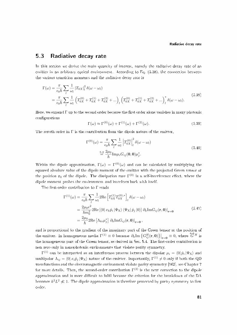
Radiative decay rate
5.3 Radiative decay rate
In this section we derive the main quantity of interest, namely the radiative decay rate of an
emitter in an arbitrary optical environment. According to Eq. (5.38), the connection between
the various transition moments and the radiative decay rate is
Γ(ω) =π
ε0~∑l
1
ωl|T0X |2l δ(ω − ωl)
=π
ε0~∑l
1
ωl
(T
(0)0X + T
(1)0X + T
(2)0X + ...
)l
(T
(0)0X + T
(1)0X + T
(2)0X + ...
)∗lδ(ω − ωl).
(5.38)
Here, we expand Γ up to the second order because the rst order alone vanishes in many photonic
congurations
Γ(ω) ≈ Γ(0)(ω) + Γ(1)(ω) + Γ(2)(ω). (5.39)
The zeroth order in Γ is the contribution from the dipole nature of the emitter,
Γ(0)(ω) =π
ε0~∑l
1
ωl
∣∣∣T (0)0X
∣∣∣2lδ(ω − ωl)
5.2=
2µ0
~ImµiGij(0,0)µ∗j .
(5.40)
Within the dipole approximation, Γ(ω) = Γ(0)(ω) and can be calculated by multiplying the
squared absolute value of the dipole moment of the emitter with the projected Green tensor at
the position r0 of the dipole. The dissipation rate Γ(0) is a self-interference eect, where the
dipole moment probes the environment and interferes back with itself.
The rst-order contribution to Γ reads
Γ(1)(ω) =π
ε0~∑l
1
ωl2Re
[T
(1)0XT
(0),∗0X
]lδ(ω − ωl)
=2µ0e
2
~m20
2Re [〈0|xkpi |ΨX〉 〈ΨX| pj |0〉] ∂kImGij(r,0)|r=0
=2µ0
~2Re
[Λkiµ
∗j
]∂kImGij(r,0)|r=0 ,
(5.41)
and is proportional to the gradient of the imaginary part of the Green tensor at the position of
the emitter. In homogeneous media Γ(1) ≡ 0 because ∂kImGHij (r,0)
∣∣r=0≡ 0, where
←→G H is
the homogeneous part of the Green tensor, as derived in Sec. 5.4. The rst-order contribution is
non-zero only in nanophotonic environments that violate parity symmetry.
Γ(1) can be interpreted as an interference process between the dipolar µi = 〈0| pi |ΨX〉 andmultipolar Λij = 〈0|xipj |ΨX〉 nature of the emitter. Importantly, Γ(1) 6= 0 only if both the QD
wavefunctions and the electromagnetic environment violate parity symmetry [162], see Chapter 7
for more details. Then, the second-order contribution Γ(2) is the next correction to the dipole
approximation and is more dicult to full because the criterion for the breakdown of the DA
becomes k2L2 6 1. The dipole approximation is therefore protected by parity symmetry to rst
order.
81

Chapter 5. Multipolar Theory of Spontaneous Emission from Quantum Dots
= + + + ...+
Figure 5.2: Physical interpretation of the spontaneous-emission rate when decomposed into
the constituent orders. The nonlocal interaction between the points r and r′ within the cur-
rent density of the emitter is converted into a local interaction between the dierent multipoles
characterizing the emitter.
Semiconductor QDs have built-in asymmetries and←→Λ is generally non-zero, as is extensively
investigated in Sec. 5.6 and Chapter 6. The rst-order contribution, Γ(1), can take both positive
and negative values depending on the orientation of the emitter with respect to the nanophotonic
environment. This makes mesoscopic QDs an ideal platform for both enhancing and suppressing
light-matter interaction at the nanoscale, as is demonstrated experimentally in Ref. [26].
The second-order contribution to the radiative decay rate is given by
Γ(2)(ω) =π
ε0~∑l
1
ωl
Re[T
(2)0XT
(0),∗0X
]+ T
(1)0XT
(1),∗0X
lδ(ω − ωl)
=2µ0
~Im[
Re[Ωlkiµ
∗j
]∂k∂l + ΛkiΛ
∗lj∂k∂
′l
]Gij(r, r
′)|r=r′=0
,
(5.42)
and is proportional to the second-order derivative of the imaginary part of the Green tensor.
The rst term from the right-hand side is a result of an interference between µ and←→Ω and is
generally non-zero even for high-symmetry emitters such as atoms because some of the involved
operators have the same parity. In contrast, the second term from the right-hand side vanishes
for parity-symmetric emitters owing to the orthogonality of the underlying µ- and←→Λ -operators.
The resulting contributions are sketched in Fig. 5.2.
Finally, we introduce the normalized decay rate ΓN of an emitter as the ratio between the
decay rate in the given nanophotonic geometry and the decay rate in a homogeneous medium
ΓH
ΓN =Γ(0) + Γ(1) + Γ(2)
Γ(0)H + Γ
(2)H
. (5.43)
The normalized decay rate is often the preferred computable quantity because, unlike Γ, is
normalized to the value of the dipole moment, whose magnitude may be hard to evaluate self-
consistently. The Green tensor can be decomposed into a homogeneous part, which emulates the
behavior in a homogeneous medium, and a scattering part, which quanties only the scattered
electromagnetic waves by the surrounding inhomogeneous medium, as explained in Sec. 2.4. The
decay rate Γ(ω) can therefore be written as a sum of a homogeneous part ΓH(ω) and a scattering
82

Green's Tensor and derivatives in the vicinity of an Interface
Figure 5.3: Conguration of the problem. The emitter, which is running a quantum-mechanical
current density j(r), is located in the medium characterized by the refractive index n1 at a
distance z0 to the interface with a medium characterized by n2.
part ΓS(ω), and the normalized decay rate takes the form
ΓN = 1 +Γ
(0)S + Γ
(1)S + Γ
(2)S
Γ(0)H + Γ
(2)H
. (5.44)
In conclusion, we emphasize that this theoretical framework can be used to study the spontaneous-
emission process in any kind of emitters (atoms or molecules in X-ray spectroscopy, QDs in
nanophotonic environments, etc.), provided that their relevant wavefunctions are known. A
number of entries in←→G and its derivatives often vanish, as do certain entries in the mesoscopic
moments for symmetry reasons. The light-matter interaction beyond the dipole approximation
can therefore be easily and accurately quantied using a small number of parameters.
5.4 Green's Tensor and derivatives in the vicinity of an In-
terface
The three contributions to the decay rate, Γ ≈ Γ(0) + Γ(1) + Γ(2), are governed by products
between an emitter property (e.g., electric and magnetic dipoles or quadrupoles) and a eld
property, which is given in terms of the Green tensor and its derivatives. The emitter multipoles
are solely a property of the underlying quantum-mechanical wavefunctions; the properties of the
QD multipoles are presented in Sec. 5.6. On the other hand, the eld properties are determined
by the spatial distribution of the dielectric permittivity ε(r). Since the present thesis is largely
concerned with describing the spontaneous-emission process of QDs in the vicinity of an interface,
see Chapters 6 and 7, in this section we derive the Green tensor and its derivatives for such a
nanophotonic geometry, where we assume that the emitter is located at a distance z = z0 above
the interface, see Fig. 5.3.
As presented in Sec. 2.4, the Green tensor←→G can be written as a sum of a homogeneous term←→
GH , which is the solution to the wave equation in a homogeneous medium hosting the emitter
and characterized by n1 =√ε1µ1, and a scattering term
←→GS , which accounts for the scattered
83

Chapter 5. Multipolar Theory of Spontaneous Emission from Quantum Dots
waves by the inhomogeneous photonic structure, i.e.,
←→G =
←→GH +
←→GS . (5.45)
We rst present the contribution of the homogeneous part before returning to the scattered
contribution from the plane interface.
5.4.1 Homogeneous part of the Green tensor
In a homogeneous medium characterized by ε1 and µ1, the dyadic Green function←→GH takes the
form [72, p. 30]
←→GH(r, r′) =
[←→1 +
1
k21
∇∇]
e(ik1R)
4πR
=
[←→1 +
ik1R− 1
k21R
2
←→1 +
3− 3ik1R− k21R
2
k21R
4RR
]e(ik1R)
4πR,
(5.46)
where R = |R| ≡ |r− r′| is the relative distance between r and r′, and k21 = ω2ε1µ1. In general,
←→GH diverges when evaluated at r = r′ = r0 but the imaginary part is bounded and well-behaved,
cf. Ref. [72, p. 239]. By taking the limit of Im←→GHas R→ 0, one obtains
Im←→GH(r0, r0) =
k1
6π
←→1 . (5.47)
The Cartesian derivatives ∂x, ∂y and ∂z of←→GH are taken by writing them in a spherical coordinate
system
∂x = sin(θ) cos(φ)∂R +1
Rcos(θ) cos(φ)∂θ +
1
R
sin(φ)
sin(θ)∂φ,
∂y = sin(θ) sin(φ)∂R +1
Rcos(θ) sin(φ)∂θ +
1
R
cos(φ)
sin(θ)∂φ,
∂z = cos(θ)∂R −1
Rsin(θ)∂θ.
(5.48)
It is clear that, rst, only the operator ∂R yields a non-zero contribution, and second, that
∂x = ∂y = ∂z due to the spherical symmetry of←→GH . Moreover, it is apparent from the denition
of←→GH that
∂i = −∂′i, (5.49)
where i = x, y, z. Inserting Eq. (5.48) into Eq. (5.46) and taking the limit R→ 0 yields
∂i Im←→GH(r, r′)
∣∣∣∣r0
=←→0 . (5.50)
84

Green's Tensor and derivatives in the vicinity of an Interface
The second-order derivatives are found in a similar fashion
∂x∂x Im←→GH(r, r′)
∣∣∣∣r0
= − k31
30π
1 0 0
0 2 0
0 0 2
,
∂x∂y Im←→GH(r, r′)
∣∣∣∣r0
= +k3
1
60π
0 1 0
1 0 0
0 0 0
,
(5.51)
and all the remaining derivatives can be recast by taking advantage of the spherical symmetry
of the geometry. The compact notation of the second-order derivatives reads
∂i∂jImGHmn(r0, r0) = − [2δijδmn(2− δim) + (1− δij)(δimδjn + δinδjm)]
k31
60π. (5.52)
Derivatives with respect to r′ can be written with the help of Eq. (5.49).
To conclude, we discuss the implications of the results. The rst-order derivatives of←→GH
vanish implying that Γ(1) = 0 in homogeneous media, and the rst non-zero term beyond the
dipole approximation is Γ(2), which is proportional to the second-order derivatives of←→GH . As a
consequence, it is more dicult to break the dipole approximation in homogeneous media, since
the condition of the dipole-approximation breakdown is k21L
2 6 1 instead of the usual k1L 6 1.
This property pertains to any parity-symmetric environment as is shown in Chapter 7.
5.4.2 Scattering part of the Green tensor
Let us assume the geometry presented in Fig. 5.3, where the emitter is placed at a distance z0
above the interface. The scattering part of the Green tensor←→GS in the upper half-space equals the
reected Green tensor from the interface. Since the reection coecient depends on the incident
angle of the wave, it is convenient to perform a two-dimensional in-plane Fourier transform
of the dyadic Green function (also called the angular-spectrum representation) and apply the
Fresnel reection coecient to every Fourier component individually. The reection coecient
is polarization dependent and it is convenient to split←→GS into a sum of s- and p-polarized
components. For compact notation, we consider the normalized Green tensor←→GS =
←→GS/k1 with
normalized wavevectors kx =√
1− k2y − k2
z . The scattered part of the Green tensor can then be
written as [72]
←→GS(r, r′) =
i
8π2
∫∫ ∞−∞
dkxdky
[←→M s
ref +←→M p
ref
]ei[kx(x−x′)+ky(y−y′)+kz1 (z+z′)],
←→M s
ref =rs(kx, ky)
kz1(k2x + k2
y)
k2y −kxky 0
−kxky k2x 0
0 0 0
,
←→M p
ref =−rp(kx, ky)
(k2x + k2
y)
k2xkz1 kxkykz1 kx(k2
x + k2y)
kxkykz1 k2ykz1 ky(k2
x + k2y)
−kx(k2x + k2
y) −ky(k2x + k2
y) −(k2x + k2
y)2/kz1
,
(5.53)
85

Chapter 5. Multipolar Theory of Spontaneous Emission from Quantum Dots
where the Fresnel reection coecients are dened below. It is convenient to switch to a cylin-
drical coordinate system in the xy and kxky planes
r = (ρ cosφ, ρ sinφ, z − z′) = (x− x′, y − y′, z − z′),
k = (kρ cos kφ, kρ sin kφ, kz) = (kx, ky, kz),(5.54)
whereupon←→GS can be recast as
←→GS(r, r′) =
i
8π2
∫ ∞0
dkρkρei[kz1 (z+z′)]
∫ 2π
0
dkφ
[←→M s
ref +←→M p
ref
]eikρρ[cos kφ cosφ+sin kφ sinφ],
←→M s
ref =rs(kρ)
kz1
sin2 kφ − sin kφ cos kφ 0
− sin kφ cos kφ sin2 kφ 0
0 0 0
,
←→M p
ref =−rp(kρ)
k21
kz1 cos2 kφ kz1 sin kφ cos kφ kρ cos kφ
kz1 sin kφ cos kφ kz1 sin2 kφ kρ sin kφ
−kρ cos kφ −kρ sin kφ −k2ρ/kz1
,
(5.55)
where kz1 is xed by the dispersion relation kz1(kρ) =√
1− k2ρ. The Fresnel coecients read
rs(kρ) =µ2kz1 − µ1kz2µ2kz1 + µ1kz2
,
rp(kρ) =ε2kz1 − ε1kz2ε2kz1 + ε1kz2
.
(5.56)
The integral over kφ can be evaluated analytically with the help of
Jn(kρρ) =i−n
2π
∫ 2π
0
dkφ cos(nkφ)eikρρ cos kφ , (5.57)
where Jn is the Bessel function of the rst kind and n-th order. The resulting expression reads
←→GS(r, r
′) =
i
8π
∫ ∞0
dkρkρ[←→M s
ref +←→M p
ref
]ei[kz1 (z+z′)],
←→M sref =
rs(kρ)
k2z1
J0(kρρ) + J2(kρρ) cos 2φ J2(kρρ) sin 2φ 0
J2(kρρ) sin 2φ J0(kρρ)− J2(kρρ) cos 2φ 0
0 0 0
,
←→M pref = −rp(kρ)kz1
J0(kρρ)− J2(kρρ) cos 2φ −J2(kρρ) sin 2φ −2i
kρkz1
J1(kρρ) cosφ
−J2(kρρ) sin 2φ J0(kρρ) + J2(kρρ) cos 2φ −2ikρkz1
J1(kρρ) sinφ
2ikρkz1
J1(kρρ) cosφ 2ikρkz1
J1(kρρ) sinφ 2(kρkz1
)2J0(kρρ)
.
(5.58)
This is the nal expression for the scattering part of the Green tensor for an emitter-interface
problem. Although it does not have analytic solutions, it is written in closed form involving a
one-dimensional integral, which has to be evaluated numerically.
In the following we evaluate←→GS and its derivatives at the origin r = r′ = r0. We consider
the integrand←→GSkρ dened as
←→GS(r, r′) =
i
8π
∫ ∞0
dkρkρ←→GSkρ(ρ, φ)e2ikz1z0 , (5.59)
86

Green's Tensor and derivatives in the vicinity of an Interface
Distance to interface, z0(nm)
Nor
mal
ized
Gre
en`s
func
tion
0 100 200 300 400 5000
0.5
1
1.5
2
2.5
3GaAs-Air
GaAs-Ag
Distance to interface, z0(nm)
Nor
mal
ized
Gre
en`s
func
tion
0 100 200 300 400 5000
0.5
1
1.5
2
2.5
3GaAs-Air
GaAs-Ag
Figure 5.4: Imaginary part of the Green tensor evaluated at the origin and normalized to the
homogeneous contribution for an emitter (a) parallel and (b) perpendicular to the interface. Two
cases of interest are taken: GaAs-air and GaAs-silver interfaces.
and take the limit ρ→ 0 yielding for the integrand
←→GSkρ(r0, r0) =
1
kz1
rs − kz1rp 0 0
0 rs − kz1rp 0
0 2k2ρr
p
. (5.60)
The Green tensor at (r0, r0) has only diagonal components and, due to the in-plane cylindrical
symmetry, only two of them have a distinct functional dependence Gxx = Gyy and Gzz, cor-
responding to a dipole moment parallel and perpendicular to the interface, respectively. The
resulting normalized imaginary part obtained after evaluating Eq. (5.59) numerically and adding
the homogeneous part is depicted in Fig. 5.4 for two cases: GaAs-air and GaAs-silver interfaces.
The plotted quantity is equivalent to the normalized decay rate within the dipole approxima-
tion. The following parameters are used: vacuum wavelength λ0 = 1000 nm, n1 = 3.42 and
nAg = 0.2 + 7i.
The two dependencies are out of phase because the reected eld acquires an additional
π phase shift upon reection from the metal. The LDOS, which is proportional to the Green
function at the origin, is considerably enhanced as the emitter approaches the metal because new
near-eld decay channels arise, namely surface-plasmons polaritons (SPPs) at distances below
∼100 nm, and ohmic-lossy modes inside the metal below ∼20 nm. Coupling to these near-eld
excitations occurs for in-plane k-vectors larger than the wavevector of light k1 in GaAs. It
is straightforward to separate the dierent decay channels in the angular-spectrum formalism.
The contribution from propagating photons is found by integrating Eq. (5.59) from 0 to 1, the
surface plasmons are found between 1 and 2kSPP−1, and ohmic-lossy from 2kSPP−1 to innity,
where kSPP =√ε2/(ε1 + ε2) is the propagation wavevector for surface-plasmon polaritons. The
resulting contributions are plotted in Fig. 5.5. A perpendicular dipole couples much stronger to
surface plasmons than an in-plane dipole owing to the well-known polarization and dispersion
of surface plasmons [163, p. 25]. The weak coupling to surface plasmons by a parallel dipole
87

Chapter 5. Multipolar Theory of Spontaneous Emission from Quantum Dots
Distance to interface, z0(nm)
Nor
mal
ized
Con
trib
utio
n
0 100 200 300 400 5000
1
2
3PhotonsSPPsOhmic Losses
Distance to interface, z0(nm)
Nor
mal
ized
Con
trib
utio
n
0 100 200 300 400 5000
1
2
3PhotonsSPPsOhmic Losses
Figure 5.5: Decomposition of the normalized imaginary part of the Green tensor for an emitter
(a) parallel and (b) perpendicular to a metal interface.
represents an intrinsic limitation for the use of semiconductor QDs in plasmon-based devices.
The mesoscopic character of QDs can, however, couple to the strong perpendicular eld and
substantially enhance or suppress the coupling to surface plasmons depending on the orientation
and symmetry of the exciton wavefunction [26, 162].
The derivatives of←→GS at (r0, r0) are evaluated by dierentiating Eq. (5.58) and subsequently
taking the limit ρ→ 0. In cylindrical coordinates, the Cartesian derivatives read
∂x = cosφ∂ρ −1
ρsinφ∂φ,
∂y = sinφ∂ρ +1
ρcosφ∂φ,
∂z = ∂z,
(5.61)
thereby yielding for the rst-order derivatives
∂x←→GSkρ(r, r
′)
∣∣∣∣r0
= k2ρr
p
0 0 1
0 0 0
−1 0 0
,
∂y←→GSkρ(r, r
′)
∣∣∣∣r0
= k2ρr
p
0 0 0
0 0 1
0 −1 0
,
∂z←→GSkρ(r, r
′)
∣∣∣∣r0
=
k2z1r
p − rs 0 0
0 k2z1r
p − rs 0
0 0 −2k2ρr
p
.
(5.62)
The rst-order derivatives of←→GSkρ are generally non-zero and rst-order processes may be allowed,
in contrast to a homogeneous medium.
As for←→GS(r0, r0), the entries of the rst-order derivatives of
←→GS inherit the two functional
dependences of a parallel dipole (compare, e.g., ∂z←→GSxx and
←→GSxx) and a perpendicular dipole
88

Origin (in)dependence of the radiative decay rate
(compare, e.g., ∂z←→GSzz and
←→GSzz). Interestingly, the x- and y-derivatives are generally non-zero
and may result in a signicant contribution for QDs, since they couple to the in-plane size of
QDs (∼2030 nm), which is normally much larger than the height (∼25 nm). These in-plane
derivatives inherit the properties of the strong z-polarized plasmon eld.
The second-order derivatives←→GS at (r0, r0) are evaluated by dierentiating Eq. (5.58) twice
and taking the limit ρ→ 0
∂x∂x←→GSkρ(r, r
′)
∣∣∣∣r0
=k2ρ
4kz1
3k2z1r
p − rs 0 0
0 k2z1r
p − 3rs 0
0 0 −4k2ρr
p
,
∂y∂y←→GSkρ(r, r
′)
∣∣∣∣r0
=k2ρ
4kz1
k2z1r
p − 3rs 0 0
0 3k2z1r
p − rs 0
0 0 −4k2ρr
p
,
∂z∂z←→GSkρ(r, r
′)
∣∣∣∣r0
= kz1
k2z1r
p − rs 0 0
0 k2z1r
p − rs 0
0 0 −2k2ρr
p
,
∂x∂y←→GSkρ(r, r
′)
∣∣∣∣r0
=k2ρ
4kz1
(k2z1r
p + rs)0 1 0
1 0 0
0 0 0
,
∂x∂z←→GSkρ(r, r
′)
∣∣∣∣r0
= k2ρkz1r
p
0 0 1
0 0 0
−1 0 0
,
∂y∂z←→GSkρ(r, r
′)
∣∣∣∣r0
= k2ρkz1r
p
0 0 0
0 0 1
0 −1 0
.
(5.63)
Finally, the derivatives with respect to r′ can be calculated with the help of
∂′x = −∂x,
∂′y = −∂y,
∂′z = ∂z,
(5.64)
as can be noted from Eq. (5.58).
In conclusion, we note that all the above one-dimensional integrals have a pole at kρ = k1 and
are easily evaluated on a computer. Combined with the analytic solutions to the homogeneous
part of←→G , it allows an easy and straightforward calculation of the radiative decay rate beyond
the dipole approximation.
5.5 Origin (in)dependence of the radiative decay rate
In Sec. 5.2 it is shown that the multipole transition moments change upon a shift of the origin
of the coordinate system from O to O + a. The relevant quantity of interest, the radiative
89

Chapter 5. Multipolar Theory of Spontaneous Emission from Quantum Dots
decay rate, is, however, robust to such a shift, if the orders in the decay rate (rather than in the
multipolar moments) are collected consistently. We rst address the spontaneous decay of an
emitter in a homogeneous medium before discussing a general nanophotonic environment.
5.5.1 Spontaneous decay in a homogeneous medium
In a homogeneous medium, the Green tensor is spatially invariant and does not change upon a
shift of the coordinate system. The zeroth-order contribution, Γ(0), is therefore origin-independent
because it contains only the electric-dipole contribution. The rst-order correction, Γ(1), trans-
forms as
Γ(1)H (O + a)− Γ
(1)H (O) = −4µ0
~akRe
[µiµ∗j
]∂kImGij(r,0)|r=0 .
The rst-order derivatives of the homogeneous part of the Green tensor vanish as proved in
Sec. 5.4 leading to
Γ(1)H (O + a)− Γ
(1)H (O) ≡ 0. (5.65)
The second-order contribution
Γ(2)H (ω) =
2µ0
~Im[
Re(Ωlkiµ
∗j
)∂k∂l + ΛkiΛ
∗lj∂k∂
′l
]Gij(r, r
′)|r=r′=0
changes when O shifts to O + a as
Γ(2)H (O + a)− Γ
(2)H (O) = Im
[−akRe
(Λliµ
∗j
)− alRe
(Λkiµ
∗j
)+ alakRe
(µiµ∗j
)]∂k∂lGij(r,0)|r=0
+ Im
[−akΛ∗ljµi − alΛkiµ
∗j + alakµiµ
∗j
]∂k∂
′lGij(r, r
′)∣∣r=r′=0
.
By noting that Gij(r, r′) = Gji(r
′, r) [74], we rearrange the above equation to obtain
Γ(2)H (O + a)− Γ
(2)H (O) = Im
[−2akRe
(Λliµ
∗j
)+ alakRe
(µiµ∗j
)]∂k∂lGij(r,0)|r=0
+ Im
[−2akRe (Λ∗liµj) + alakµiµ
∗j
]∂k∂
′lGij(r, r
′)|r=r′=0
.
(5.66)
This expression vanishes for the homogeneous part of←→G , as can be checked with the help of
Eqs. (5.49) and (5.51)
Γ(2)H (O + a)− Γ
(2)H (O) ≡ 0. (5.67)
It can be shown that the property of origin independence holds up to an arbitrary expansion
order in Γ [161]. The radiative decay rate is therefore independent of the choice of the origin of
the coordinate system in a homogeneous medium
ΓH(O + a)− ΓH(O) ≡ 0. (5.68)
This important result lies at the heart of practical calculations employing the multipole expan-
sion.
90

Decay dynamics of In(Ga)As quantum dots in the vicinity of an interface
5.5.2 Spontaneous decay in an arbitrary environment
The property of origin independence cannot be generalized to an arbitrary environment because,
in general, the Green tensor is spatially dependent. This implies that the LDOS is also spatially
dependent and all the orders (including the dipole contribution) are dependent on the origin of
the coordinate system. The expansion point O then has to be dened such that the multipole
expansion converges fastest. It can be shown that O coincides with the largest transition den-
sity [160], which corresponds to the excitonic density for QDs. The center-of-mass coordinate of
the exciton contains the highest excitonic density and we therefore obtain for O
O =mere +mhrhme +mh
, (5.69)
where me and mh (re and rh) are the eective-masses (central coordinates) of electrons and
holes, respectively.
In conclusion, we have been able to successfully address the fundamental problem of the ori-
gin dependence of the multipole expansion in two steps. First, collecting consistently the orders
in Γ rather than in the multipole moments results in origin independence for the homogeneous-
medium contribution in the spontaneous decay. In the second step we have rigorously dened
a natural choice for the origin of the coordinate system O, which is relevant in inhomogeneous
nanophotonic environments. We have therefore justied formally the use of the multipole ex-
pansion for modelling accurately and eciently the spontaneous-emission process.
5.6 Decay dynamics of In(Ga)As quantum dots in the vicin-
ity of an interface
Quantum dots are mesoscopic entities extended over tens of nanometers and they may break
the dipole approximation as argued in the introduction of the present chapter. In this sec-
tion we employ the developed multipolar theory to provide a profound understanding of the
spontaneous-emission process from QDs. In particular, we are interested in determining the
multipolar moments that may yield a signicant contribution to the light-matter interaction and
compete with the electric-dipole contribution. The rst-order mesoscopic moment←→Λ contains
9 entries and the second-order mesoscopic moment←→Ω has 27 entries. Many of them, however,
vanish or are negligible for symmetry reasons, and only a few capture the essential physics lead-
ing to a simple and intuitive interpretation of the light-matter interaction. For concreteness we
consider the spontaneous decay of a QD placed at a distance z = z0 above a silver interface.
Such a conguration was realized experimentally in Ref. [26], where QDs showed pronounced
deviations from the dipole theory. In Chapter 6 we present experimental data demonstrating
the breakdown of the dipole approximation for QDs placed in the vicinity of a dielectric-air
interface [164].
We assume the QDs to be lens shaped with in-plane cylindrical symmetry but with no well-
dened parity symmetry in the growth direction, in good agreement with the shape of self-
assembled In(Ga)As QDs [44]. We note that this analysis is not bound to this particular QD
91

Chapter 5. Multipolar Theory of Spontaneous Emission from Quantum Dots
shape and is also valid for pyramidal or in-plane elliptical QDs. The exciton state in In(Ga)As
QDs is found in the strong-connement regime [84] and, as argued in Sec. 2.2, we employ the
single-particle eective-mass approximation to model the electron Ψe and hole Ψhh wavefunctions
Ψe(r) = us(r)ψe(r),
Ψhh(r) = uhh(r)ψhh(r),(5.70)
where us (uhh) is the conduction-band (valence-band) Bloch function at the Γ-point in k-space,
and ψ(r) is the slowly varying envelope subject to the eective-mass Schrödinger equation. Due
to the exchange interaction, the two bright excitons are linearly polarized along x = [1, 1, 0] and
y = [1,−1, 0] as derived in Sec. 2.2. We consider one of the bright excitons uhh = ux, where ux
is the valence-band Bloch function with odd symmetry along x, but note that the properties of
the y-polarized exciton are derived analogously.
5.6.1 Zeroth-order contribution
The zeroth-order contribution to the radiative decay rate stems from the electric-dipole character
of the QD and reads (cf. Eq. (5.40))
Γ(0) =2µ0e
2
~m20
Im 〈0| pi |ΨX〉Gii(r0, r0) 〈ΨX| pj |0〉 . (5.71)
The transition moment can be simplied as follows
〈0| pi |ΨX〉 = 〈uxψhh| pi |usψe〉 ≈∫
d3rψ∗hhψeu∗xpius
≈N∑q=1
ψ∗hh(Rq)ψe(Rq)
∫U.C.
d3ru∗x(r)pius(r) ≈ 〈ψhh|ψe〉 pcv,(5.72)
where pcv = 1VU.C.
〈ux| px |us〉U.C. is the Bloch transition matrix element and is evaluated within
one single unit cell. The rst approximation in the above equation assumes that the momentum
operator acting on the electron slowly varying envelope has a negligible contribution because ψe
varies much slower than ue. We then have neglected the spatial variation of the slowly varying
envelopes over one unit cell and have separated the integral into a sum over all the unit cells
comprising the QD. Finally, we have converted the sum back into an integral involving the slowly
varying envelopes. We thus obtain for the rate
Γ(0) =2µ0e
2
~m20
|pcv|2 |〈ψhh|ψe〉|2 ImGxx(r0, r0). (5.73)
The imaginary part of Gxx can be recast with the help of Eqs. (5.46), (5.59) and (5.60)
ImGxx(r0, r0) = ImGHxx(r0, r0) + ImGSxx(r0, r0)
=k1
6π+k1
8πRe
[∫ ∞0
dkρkρkz1
(rs − kz1rp)
].
(5.74)
92

Decay dynamics of In(Ga)As quantum dots in the vicinity of an interface
ux ψhh Ψhh us ψe Ψe
x -1 1 -1 1 1 1
y 1 1 1 1 1 1
z 1 0 0 1 0 0
Table 5.2: Symmetries of the electron and hole wavefunctions for a lens-shaped QD. `1' denotes
even parity, `-1' odd parity and '0` no parity.
5.6.2 First-order contribution
We recall Γ(1) from Eq. (5.41)
Γ(1) =2µ0
~02Re
[Λkiµ
∗j
]∂kImGij(r, r0)|r=r0
. (5.75)
The only non-zero component of the dipole transition moment is µx = 〈0| px |ΨX〉 because we
consider the x-polarized exciton. The sum over j therefore collapses yielding
Γ(1) =2µ0
~02Re [Λkiµ
∗x] ∂kImGix(r, r0)|r=r0
. (5.76)
In the following, we investigate the rst-order mesoscopic moment←→Λ
Λki =e
m0〈0| (xk − x0,k)pi |ΨX〉 =
e
m0〈uxψhh| (xk − x0,k)pi |usψe〉 . (5.77)
The choice of x0 and y0 is provided naturally by the cylindrical symmetry of the QD. Due to
a lack of parity symmetry of the QD wavefunctions in the z-direction, z0 cannot be chosen by
symmetry and we dene it as the z-component of the exciton center-of-mass coordinate as argued
in Eq. (5.69).
The 9 entries in←→Λ can be reduced to 2 non-zero entries using the symmetry properties of
the underlying wavefunctions. The valence-band Bloch function ux inherits the symmetry of the
px orbital and therefore exhibits odd parity ("-1") in the x-direction and even parity ("+1")
in y and z. The conduction-band Bloch function ue inherits the spherical symmetry of the s-
orbital and therefore contains even parity in all directions. Since the eective-mass theory is an
envelope-function formalism, the slowly varying envelopes ψ inherit the symmetry of the QD.
Table 5.2 summarizes these considerations. Applying parity-symmetry arguments, we nd that
only Λxz and Λzx contain non-zero entries and thus
←→Λ =
0 0 Λxz
0 0 0
Λzx 0 0
. (5.78)
This yields for the rst-order contribution
Γ(1) =2µ0
~2(Re [Λxzµ
∗x] ∂xImGzx(r, r0)|r0 + Re [Λzxµ
∗x] ∂zImGxx(r, r0)|r0
). (5.79)
93

Chapter 5. Multipolar Theory of Spontaneous Emission from Quantum Dots
Distance to interface, z0 (nm)
Qu
antu
m-d
ot
dec
ay r
ate
(ns-1
)
Silver
GaAs
Silver
GaAs
z
z
(a)
(b)
Figure 5.6: Experimental demonstration of the breakdown of the dipole approximation taken
from Ref. [26]. The decay rate of quantum dots close to a metal interface was measured for (a)
direct and (b) inverted QDs relative to the interface. The black dashed line denotes the dipole
theory, the triangles the data points and the colored solid lines the t.
To understand which of the two non-zero mesoscopic moments may be relevant and compete
with the electric-dipole contribution, we analyze their functional dependence and compare it to
the experiment performed in Ref. [26]. In the experiment, the QD spontaneous-emission rate
was found to be inhibited with respect to the dipole theory for the geometry illustrated by the
inset of Fig. 5.6(a). In contrast, the inverted structure shown in Fig. 5.6(b) showed an increase
in the rate; we note that the QDs from the direct and inverted structures would exhibit the same
rates, if they behaved as point dipoles, as shown by the dashed line corresponding to the dipole
theory. This breakdown of the dipole approximation was found to be caused by the mesoscopic
moment Λxz and we explain the reason in the following.
The two mesoscopic moments provide dierent contributions to the light-matter interaction
strength as shown in Fig. 5.7. If compared to Fig. 5.6, it follows that Λzx does not reproduce
the functional dependence observed in experiment. The contribution of Λzx aects mostly the
"phase" of the oscillations, a behavior that was not observed in experiment. This implies that
Λzx Λxz and in the following we give a qualitative explanation for this. The mesoscopic
moment Λzx = (e/m0) 〈ψh |zpx|ψe〉 scales with the height of QDs because of the z-operator in
the matrix element. In contrast, Λxz = (e/m0) 〈ψh |xpz|ψe〉 scales with the in-plane size, which
is much larger than the height for In(Ga)As QDs. As a consequence, Λzx is expected to yield
negligible contribution to the decay rate and this is what we show quantitatively in Appendix C.
Only Λxz may potentially attain large values and compete with the electric-dipole contribution
94

Decay dynamics of In(Ga)As quantum dots in the vicinity of an interface
0 100 200 300 400 5000
1
2
3
Distance to interface, z (nm)
Nor
mal
ized
dec
ay r
ate Direct
DAInverted
0
0 100 200 300 400 5000
1
2
3
Distance to interface, z (nm)
Nor
mal
ized
dec
ay r
ate Direct
DAInverted
0
Figure 5.7: Normalized decay rate for (left) Λxz and (right) Λzx contribution. The size of the
mesoscopic moments Λij/µx is taken to be 10 nm, which is of the order of the size of In(Ga)As
QDs. "DA" denotes the dipole approximation.
Γ(0) and we may write
←→Λ '
0 0 Λ
0 0 0
0 0 0
, (5.80)
where Λ = Λxz. In the experiment from Ref. [26] a value of Λ/µ ' 10 nm was measured, which
is surprisingly large and provides an additional degree of freedom for the light-matter interaction
with QDs, in addition to the dipole moment. Evaluating Λ/µ self-consistently and understanding
the microscopic origin for the large mesoscopic moment is not straightforward and we return in
Chapter 6 to accomplish this task. We nally obtain for the rst-order contribution
Γ(1) =2µ0
~2Re [Λxzµ
∗x] ∂xImGzx(r, r0)|r0 . (5.81)
5.6.3 Second-order contribution
As shown in Sec. 5.3, the second-order correction to the decay rate is
Γ(2) =2µ0
~Im[
Re[Ωlkiµ
∗j
]∂k∂l + ΛkiΛ
∗lj∂k∂
′l
]Gij(r, r
′)|r=r′=r0
.
In the following we analyze the symmetry properties of the second-order mesoscopic moment
Ωijk. With the help of Table 5.2, it can be shown that only 7 entries out of 27 do not vanish:
Ωxxx, Ωxzz, Ωzxz = Ωxzz, Ωyyx, Ωyyz, Ωzzx and Ωzzz. The contribution of the entries Ωyyz and
Ωzzz vanishes in the proximity of an interface because the corresponding derivatives of the Green
tensor are zero, see Eq. 5.63. In Appendix D we show that the contribution of the mesoscopic
moment Ωzzx is negligible because it couples to the height of QDs, which is small. Analogous
reasoning applies to Ωxzz. Only Ωxxx and Ωyyx therefore may yield non-negligible contribution
95

Chapter 5. Multipolar Theory of Spontaneous Emission from Quantum Dots
0 100 200 3000.5
1
1.5
2
Distance to interface, z0 (nm)
Nor
mal
ized
dec
ay r
ate
DirectDAInverted
0 100 200 3000.5
1
1.5
2
Distance to interface, z0 (nm)
Nor
mal
ized
dec
ay r
ate
DirectDAInverted
Figure 5.8: Contribution of the second-order mesoscopic moments (left) Ωxxx and (right) Ωyyx
to the decay rate. Note that the direct and inverted structures yield the same contribution.
to the decay rate, and the second-order correction reads
Γ(2) =2µ0
~
Re [Ωxxxµ∗x] ∂x∂x ImGxx(r, r0)|r0 + Re [Ωyyxµ
∗x] ∂y∂y ImGxx(r, r0)|r0 +
+ Re [Ωxzzµ∗x] ∂x∂z ImGzx(r, r0)|r0 − |Λxz|
2∂x∂x ImGzz(r, r0)|r0 ]
(5.82)
All three second-order mesoscopic moments contribute with the same sign for the direct and
inverted structures. Due to the fact that we are considering relatively large wavelengths of
∼1000 nm corresponding to about ∼300 nm in GaAs, the second-order contribution Γ(2) is sub-
stantially reduced relative to the rst-order contribution as shown in the following. This may,
however, not hold for QDs operating at shorter wavelengths.
In the following, we estimate the impact of the second-order mesoscopic moments on the
decay rate of QDs near a silver interface. From the cylindrical symmetry of the QDs it follows
that Ωxxx = Ωyyx and are scaled by the in-plane size of QDs. Their contribution is, however,
not identical since they couple to dierent eld components
Ωxxxµx
=Ωyyxµx
=
⟨uxψhh
∣∣x2px∣∣usψe⟩
〈ψhh|ψe〉 pcvUCDA≈
⟨ψhh
∣∣x2∣∣ψe⟩
〈ψhh|ψe〉, (5.83)
where in the last step the term x2 was pulled outside the Bloch matrix element along with
the slowly-varying envelopes because the corresponding term stems from the expansion of the
eld, which may be considered constant over one unit cell. The justication of this unit-cell
dipole approximation (UCDA) is presented in Appendix E, where it is shown that UCDA is
excellent for most practical purposes owing to the small size of unit cells of ∼ 0.5 nm. The
quantitative estimations performed in Chapter 6 yield an in-plane extent HWHM for the QD
wavefunctions of about 15 nm, which corresponds to a value of the second-order mesoscopic
moments of Ωxxx/µx = Ωyyx/µx ∼ 225 nm2. These moments have a negligible contribution to
light-matter interaction as shown in Fig. 5.8 because k21 is small at a wavelength of 1 µm and the
mesoscopic terms are not large enough to compensate this. We therefore neglect the contribution
from Ωxxx and Ωyyx in the present thesis.
96

Decay dynamics of In(Ga)As quantum dots in the vicinity of an interface
0 100 200 3000
1
2
3
Distance to interface, z0 (nm)
Nor
mal
ized
con
trib
utio
n
Normalized ΓDA(ω)Normalized Γ(ω)Radiation ModesSPPs
0 100 200 3000
1
2
3
Distance to interface, z0 (nm)
Nor
mal
ized
con
trib
utio
n
Normalized ΓDA(ω)Normalized Γ(ω)Radiation ModesSPPs
Figure 5.9: Decomposition of QD decay mechanisms in front of a silver mirror for the (left) direct
and (right) inverted structures. The mesoscopic moment Λ contributes mainly to the excitation
of surface plasmons with large eld gradients, while the coupling to radiation modes is largely
unaected.
The nal expression for the decay rate, which takes into account the aforementioned assump-
tions and justications, reads
Γ(ω) =2µ0
~
(|µx|2 ImGxx(r0, r0) + 2Re [Λxzµ
∗x] ∂xImGzx(r, r0)|r0
− |Λxz|2 ∂x∂x ImGzz(r, r0)|r0 ) .(5.84)
This is a general expression for the light-matter interaction between QDs and light and can be
applied to arbitrary nanophotonic environments. Every term in the above equation is analyzed
in detail in Chapter 7, where it is shown that QDs are the very rst known quantum emitters
that can probe simultaneously electric and magnetic elds at optical frequencies.
Finally, we note that decomposing the decay of the QD into dierent types of excitations can
be done using the angular-spectrum representation analogously to the dipole theory presented in
Sec. 5.4. It is apparent from Fig. 5.9 that the coupling to surface plasmons (SPPs) is very dierent
for the direct and inverted structures. This is because the dipole-moment µ and mesoscopic-
moment Λ operators have dierent parity along the z-direction and their interference changes
from destructive for the direct structure to constructive for the inverted geometry. The coupling
to surface plasmons βpl , which is dened as the ratio between the coupling rate to plasmons
divided by the coupling to all the available optical modes
βpl =ΓSPPs(ω)
ΓQD(ω)=
ΓSPPs(ω)
Γphotons(ω) + ΓSPPs(ω) + Γlosses(ω), (5.85)
can therefore be tuned by the interference between the dipole and mesoscopic moment of the QD
Γ(1), see Fig. 5.10. We therefore conclude that QDs have an additional optical degree of freedom,
the mesoscopic moment Λ, which breaks the dipole nature of QDs and may be used not only
to tailor the light-matter interaction strength but also to tune other emission-related properties
such as the radiation pattern or the polarization of the spontaneously emitted photons.
97

Chapter 5. Multipolar Theory of Spontaneous Emission from Quantum Dots
0 100 200 3000
20
40
60
80
100
Distance to interface, z0 (nm)
Cou
plin
g to
SP
Ps,
βpl
(%
)
DADirectInverted
Figure 5.10: Eciency of coupling to plasmons βpl for mesoscopic QDs in front of a silver
mirror. Destructive (constructive) interference between µ and Λ results in suppressed (enhanced)
coupling to surface-plasmon polaritons for the direct (inverted) structure.
5.7 Summary
In the present chapter we have developed a comprehensive theory describing the process of spon-
taneous emission of light from quantum emitters beyond the dipole approximation. We have
performed a multipolar expansion in the eld and have collected the multipolar contributions up
to the second order in the radiative decay rate. A fundamental characteristic of the multipolar
expansion is the dependence of the multipolar moments on the choice of the origin of the coordi-
nate system, which may compromise the practical utility of the expansion. We have shown that
by carefully collecting the orders in the decay rate rather than transition moments, and by rigor-
ously dening the origin of the coordinate system, the origin dependence is not an issue and the
multipolar moments have a well-dened physical meaning. We have used the developed theory to
describe the spontaneous-emission process from self-assembled In(Ga)As and have found that the
QDs are mesoscopic entities possessing a large mesoscopic moment Λ, which may compete with
the dipole moment µ in light-matter interactions. The resulting expression for the decay rate is
simple and intuitive and can be applied to describe the spontaneous-emission process in arbitrary
nanophotonic environments. There are two questions left to be answered. First, the microscopic
origin of the large mesoscopic moment Λ has been unclear so far and we devote Chapter 6 to
answer this question. Second, the implications of the dipole-approximation breakdown on the
fundamental nature of the spontaneous-emission process is discussed in Chapter 7.
98

Chapter 6
Unraveling the Mesoscopic
Character of Quantum Dots in
Nanophotonics
The central physical process studied in the elds of quantum optics, cavity-quantum electrody-
namics, nano-optics and nanophotonics is the spontaneous emission of nonclassical light from
quantum emitters. State-of-the-art fabrication techniques enable the realization of advanced
photonic nanostructures such as photonic-crystal cavities and waveguides [22], or plasmonic
nanoantennas [165], which accurately and eciently tailor the density of optical states allowing
for the desired spontaneous-emission decay time [166], state of polarization [167] and direction of
propagation [21] of the spontaneously-emitted photons. The ability to control the spontaneous-
emission process provides envisioning prospects for the realization of ecient on-chip quantum-
information protocols interfacing stationary and ying quantum bits, as well as developing a new
understanding of fundamental CQED phenomena happening in a solid-state platform, such as
the Lamb shift [6] and other largely unexplored energy non-conserving processes [168]. So far,
at the heart of the light-matter-interaction studies has been the dipole approximation, which
has become a standard approximation used in quantum-optics textbooks [75]. According to the
dipole theory, the variation of the electromagnetic eld over the extent of the emitter is neglected
completely, which renders emitters to appear dimensionless entities when interacting with light.
The enormous success of the dipole theory in practical experiments has resulted in photonic
environments that have been engineered to target solely the dipole moment of emitters for tai-
loring the coupling to light in the desired fashion. For instance, a point-like emitter may couple
to an optically large plasmonic nanoantenna [167], where the interference among the multipolar
moments of the antenna may result in a highly directional emission of the single photons. Sim-
ilarly, the highly directional LDOS for in-plane oriented dipoles in photonic-crystal waveguides
leads to emission of single photons into the waveguide mode with near-unity probability [21].
Notwithstanding this extraordinary theoretical and experimental progress, the supremacy of the
99

Chapter 6. Unraveling the Mesoscopic Character of Quantum Dots in Nanophotonics
xyz(a) (b)
xyz
Figure 6.1: Unraveling the mesoscopic character of QDs in the vicinity of a GaAs-air interface.
The presence of the interface breaks the parity symmetry of the environment in the z-direction.
Since reections occur at the interface (the circular white arrow), the imaginary part of the elec-
tric eld E(r) generated by the electric-dipole component, which triggers spontaneous emission,
inherits this lack of symmetry and is curved (indicated by the green arrow). (a) In the dipole
approximation, the QD microscopic current j(r) (brown arrow) perceives only the parallel com-
ponent but not the out-of-plane component (the "curvature") of the electromagnetic eld at its
position. (b) In In(Ga)As self-assembled QDs, the current density ows along a curved path that
resembles the shape of the eld environment thereby exchanging energy more eciently with it.
As a consequence, the spontaneous-emission decay rate is enhanced and the photons (red arrows)
are emitted at a faster rate compared to the case in (a).
dipole approximation was recently challenged by the observation that self-assembled In(Ga)As
QDs do not follow the dipole theory when positioned in front of a silver mirror [26]. As presented
in Chapter 5, the breakdown of the dipole approximation is explained by a phenomenologically
dened mesoscopic moment, which may compete with the dipole contribution in light-matter
interactions, but no microscopic understanding of the eect has been established so far. Such an
understanding is, however, highly relevant for the use of QDs in the aforementioned studies and
applications.
In the present chapter we develop a microscopic theory of the QD wavefunctions that provides
physical insight into the mesoscopic character of QDs and has resulted in the publication of
Ref. [164]. Previous theories of light-matter interaction beyond the dipole approximation have
investigated mesoscopic eects at the level of the QD spatial extent and symmetry and have
discarded their atomistic nature because the unit cells are small compared to the wavelength
of light [83, 169173]. These approaches fail to explain the large mesoscopic moment observed
experimentally and the fundamental principle conferring mesoscopic properties to QDs has been
therefore unknown. In the present work we nd that, surprisingly, the atomistic nature plays
a crucial role and explains the mesoscopic character of QDs. We show that the mesoscopic
moment originates from structural inhomogeneities at the crystal-lattice level, which generate
100

Microscopic model for mesoscopic quantum dots
large circular quantum-mechanical current densities owing inside the QD over mesoscopic length
scales. The inhomogeneities are related to the change in the periodicity of the underlying crystal
lattice of the QD, which, in turn, is caused by the lattice-mismatched growth of self-assembled
QDs. Since Bloch functions with dierent periodicities cannot remain in phase throughout the
QD, this necessarily leads to a phase gradient and a resulting quantum-mechanical current in
the growth direction of the QD, which gives rise to the mesoscopic moment. Our ndings enrich
the understanding of the QD spontaneous-emission process, and can be immediately used for
engineering complex nanophotonic environments that maximize the coupling to the current-
density pattern of the QD. Such an example is shown in Fig. 6.1 in the vicinity of a dielectric-air
interface, where the electromagnetic eld is curved due to the lack of parity symmetry of the
environment in the z-direction. Matching this eld shape with a curved current density that
is running through self-assembled QDs, see Fig. 6.1(b), results in an enhanced light-matter
interaction strength compared to QDs obeying the dipole approximation shown in Fig. 6.1(a).
Our ndings are supported by experimental data showing an increased radiative decay rate
of QDs in the vicinity of an air interface compared to the dipole theory. By applying the
developed multipolar theory of spontaneous emission to the experimental results, we extract a
surprisingly strong variation of the mesoscopic moment across the inhomogeneously broadened
emission spectrum of QDs. Our ndings provide a new optical degree of freedom of QDs that
can be used in state-of-the-art CQED experiments as well as in more complex atomistic models
that take into account distortions of the nanoscopic lattice of QDs.
6.1 Microscopic model for mesoscopic quantum dots
The central quantity describing the optical transition from the excited state Ψe to the ground
state Ψg of a QD is the dipole moment µ = (e/m0) 〈Ψg|p|Ψe〉. We consider the x-polarized
exciton µ = µx, as sketched in Fig. 6.1, where x is the Cartesian unit vector. Until recently,
µ was the only QD property used to describe the interaction with light. Recent experimental
studies of spontaneous emission from QDs at nanoscale proximity to a mirror revealed strong
deviations from the dipole theory, which have been accounted so far by the phenomenologically
dened mesoscopic moment Λ = (e/m0) 〈Ψg|xpz|Ψe〉. Combined with the microscopically well-
understood dipole moment, this quantity accounts for the interaction with light caused by the
extended mesoscopic nature of QDs. In Ref. [26], a large value of Λ/µ ' 10 nm was measured and
approaches k−1GaAs = λ/(2πnGaAs), where nGaAs is the refractive index of GaAs. In the following
we show that such a large value cannot be obtained using the standard eective-mass theory,
and that a more extended description is required.
As presented in Sec. 5.6, the standard textbook approach for evaluating the transition dipole
moment µ is to assume that the envelope function ψ varies slowly over a unit cell so that µ
can be written as a product of the Bloch matrix element pcv and a three-dimensional overlap
integral between the envelope functions, i.e., µ = (e/m0) 〈uxψg|px|ueψe〉 ≈ (e/m0)pcv 〈ψg|ψe〉,where pcv = V −1
UC
∫UC
d3ru∗xpxue is given by an integral over the unit cell with VUC being the
unit-cell volume. In other words, the transition dipole moment is primarily a unit-cell eect and
101

Chapter 6. Unraveling the Mesoscopic Character of Quantum Dots in Nanophotonics
is marginally aected by the envelope functions, as their overlap is normally close to unity [84].
Importantly, the large mesoscopic strength Λ/µ observed experimentally cannot be reproduced
by a similar calculation, which leads to
Λ =e
m0[〈ψg |x|ψe〉 〈ux |pz|ue〉UC + 〈ψg|ψe〉 〈ux |xpz|ue〉UC
+ 〈ψg |xpz|ψe〉 〈ux|ue〉UC + 〈ψg |pz|ψe〉 〈ux |x|ue〉UC] ,(6.1)
where 〈〉UC ≡ V −1UC
∫UC
d3r denotes integration over a unit cell. The rst three contributions
vanish for symmetry reasons. The fourth contribution is vanishingly small and does not scale
with the QD size: for Gaussian envelopes allowing for realistic mutual displacements of 12 nm
between the electron and the hole in the growth direction (note that the integral vanishes in
the absence of such a displacement) we estimate Λ/µ ∼ 10−4nm. This suggests that the large
mesoscopic strength Λ/µ ∼ 1020 nm observed experimentally cannot be explained solely by the
envelope wavefunctions. In the following we show that structural gradients at the nanoscopic
crystal-lattice length scale can explain the eect.
It is often assumed that solid-state emitters have a homogeneous chemical composition, which
renders substantial simplications in the computation of the wavefunctions. In particular, the
homogeneity justies the use of bulk-material Bloch functions, and only the slowly varying en-
velopes describe the properties of the nanostructure. This assumption works excellently for
quantum wells and lattice-matched QDs, where the structures are either strain free or pseudo-
morphically grown on the substrate material. As a result, the wavefunctions are conned to a
chemically homogeneous region of space. InAs QDs are grown by self-assembly induced by strain
relaxation, a violent process that unavoidably leads to the generation of chemical gradients at
the crystal-lattice level. In particular, large lattice-constant shifts are observed in the growth di-
rection of QDs [44, 174]. This limits the applicability of the standard envelope-function theories
and, in particular, of the eective-mass formalism. A complete theory encompassing the spatial
position and symmetry of every single atom comprising the QD would generally be required.
Remarkably, the essential physics of the mesoscopic light-matter interaction can be captured
by only a minor extension of the eective-mass theory. We assume that the lattice periodicity
changes at a certain position z = zT along the QD height by an amount ∆al = 110 pm at a
central value al = 605 pm as found experimentally in Ref. 174, see Fig. 6.2(a). This corresponds
to a relative lattice-constant shift of 18%, which is strain induced and is substantially larger
than the lattice-constant mismatch between InAs and GaAs of 7%. We note that, in general, the
lattice periodicity changes twice: rst it is expanded at the QD base (GaAs-In(Ga)As transition)
before being shrunk back at the QD tip (In(Ga)As-GaAs transition). Since the exciton is spa-
tially conned near the tip where the indium concentration is highest [44], we only consider the
second transition region. The Bloch functions change periodicity as well, cf. Fig. 6.2(b), and we
model this by expanding them in a Fourier series with a position-dependent lattice wavevector
102

Microscopic model for mesoscopic quantum dots
hhe
(a) (c) 1
-1
(b)Bloch function
0
Figure 6.2: Sketch illustrating the microscopic model for mesoscopic QDs. (a) The atomic
lattice inside the QD is assumed to change periodicity at the position z = zT . (b) Sketch of how
the Bloch function u2x of the atomic lattice varies spatially inside the QD. (c) Illustration of the
matrix elements 〈px〉 ≡ 〈ux|px|ue〉 and 〈pz〉 ≡ 〈ux|pz|ue〉 for the three colored unit cells in (a).
The symmetry of the integrand is broken in the transition region around z = zT giving rise to
pronounced mesoscopic eects.
kl(z)
ux(r) =∑m
am(y, z) sin[mkl(z)x]
ue(r) =∑n
bn(y, z) cos[nkl(z)x].(6.2)
This Ansatz ensures opposite parity of the conduction- and valence-band Bloch functions along
x. Furthermore, we implicitly assume the shape of the Bloch functions to remain the same,
and only their periodicity to vary spatially. Now we return to the evaluation of the mesoscopic
moment and separate the slowly- and rapidly-varying contributions as
Λ =e
m0
N∑q=1
ψ∗g(Rq)Xqψe(Rq)
∫UC
d3ru∗x(r)pzue(r), (6.3)
where Rq denotes the position of the q-th unit cell and N is the total number of unit cells in the
QD. In a homogeneous region of the QD (the blue unit cell in Fig. 6.2(a)) the unit-cell integrand
of Eq. (6.3) is odd in x- and z-directions, cf. Fig. 6.2(c), which leads to a vanishing integral.
However, in the transition region around z = zT strong gradients are present, which destroy
the parity of the integrand (see the pink and green unit cells in Fig. 6.2(a,c)) and generate a
substantial contribution to Λ.
In the following, we calculate the mesoscopic moment Λ and show that its magnitude is
sensitive to the QD geometry. With the Ansatz in Eq. (6.2) we rst compute the dipole Bloch
matrix element pcv = 〈px〉UC
pcv =1
VUC
∫UC
d3ru∗xpxus
=i~VUC
∑n,m
∫UC
d3ra∗m(r)bn(r) sin[mkl(z)x]nkl(z) sin[nkl(z)x]
=i~VUC
∑n
∫UC
d3ra∗n(r)bn(r)nkl(z) sin2[nkl(z)x].
(6.4)
103

Chapter 6. Unraveling the Mesoscopic Character of Quantum Dots in Nanophotonics
Since Λ contains the z-polarized Bloch matrix element 〈ux| pz |us〉, we evaluate it with the help
of Eq. (6.3)∫UC
d3ru∗x(r)pzue(r) = −i~∑m,n
∫UC
d3ra∗m(r) sin[mkl(z)x]∂zbn(r) cos[nkl(x)]
' i~∑m,n
∫UC
d3ra∗m(r)bn(r)∂kl(z)
∂zsin[mkl(z)x]nx sin[nkl(z)x],
(6.5)
where we have assumed that only the periodicity of the Bloch functions changes while the func-
tions a(r) and b(r) are independent of z. With this in mind, the mesoscopic moment Λ can be
written as
Λ =
N∑q=1
ψ∗hh(Rq)Xqψe(Rq)∑m,n
∫UC
d3ra∗m(r)bn(r)∂kl(z)
∂zsin[mkl(z)x]n(x+Xq) sin[nkl(z)x].
We assume that kl is varying linearly over several lattice constants as shown qualitatively in
Refs. [44, 174], and we can therefore pull it in front of the integral over the unit cell. The term
containing x vanishes because it renders the integral odd yielding for the mesoscopic moment
Λ =
N∑q=1
ψ∗hh(Rq)X2qψe(Rq)
∂kl(z)
∂z
∣∣∣∣z=Zq
∑m,n
∫UC
d3ra∗m(r)bn(r) sin[mkl(z)x]n sin[nkl(z)x]
'Ncells∑q=1
ψ∗hh(Rq)X2qψe(Rq)
1
kl
∂kl∂z
∣∣∣∣z=Zq
∑m,n
∫UC
d3ra∗m(r)bn(r) sin[mkl(z)x]nkl sin[nkl(z)x]
' 1
kl
⟨ψhh(r)
∣∣∣∣x2 ∂kl(z)∂z
∣∣∣∣ψe(r)
⟩pcv.
(6.6)
The resulting expression for the mesoscopic strength Λ/µ reads
Λ
µ=
1
kl
⟨ψg(r)
∣∣x2 [∂zkl(z)]∣∣ψe(r)
⟩〈ψg(r)|ψe(r)〉
. (6.7)
We have thus been able to express a crystal-lattice eect in terms of the slowly varying envelope
functions. The mesoscopic strength scales quadratically with the in-plane size of the QD, Λ/µ ∼L2r, because the term
⟨ψg∣∣x2 [∂zkl(z)]
∣∣ψe⟩ contains the variance of the exciton wavefunction in
the x-direction. Moreover, it increases with decreasing QD height, Λ/µ ∼ L−1z , since in shallow
QDs the relative importance of the lattice-constant transition region is increased.
Equation (6.7) is the most general expression for Λ/µ that can be simplied in order to
obtain an intuitive analytical expression. In this regard, we assume a sharp transition in the
lattice constant ∂zkl = ∆klδ(z − zT ) for simplicity. This approximation is excellent because
∂zkl is multiplied by a slowly varying integrand. Throughout this paper we consider zT = 0,
which coincides with the center of the QD wavefunctions, for the following reason. According to
Ref. [44], the shift happens at the tip of the QD, which turns out to be close to the position where
the QD wavefunctions are localized since the indium concentration is highest here. We therefore
expect zT to coincide with the region of high excitonic density. We have explicitly checked that
our results are robust to small shifts of zT of ±1 nm that may occur in practice. A quantitative
justication requires the knowledge of the distribution of both the material composition and the
104

Microscopic model for mesoscopic quantum dots
5 10 15 20 250
20
40
60
80
In−plane QD radius (nm)
|Λ/µ
| (nm
)
Figure 6.3: The mesoscopic strength as a function of the in-plane size of the QD for three xed
QD heights.
local lattice parameter throughout the QD, parameters which are dicult to measure and are
generally unknown. For the particular case of in-plane rotationally symmetric Gaussian slowly
varying envelopes we obtain the following analytic expression for the mesoscopic strength
Λ
µ= −∆al
al
√1 + ξz
4π
σ2r
σz, (6.8)
where σz is the height (HWHM) of the electron envelope, σr the QD radius, ∆al/al the relative
lattice-constant shift and ξz ≈ 5 is the ratio between the electron and hole eective masses [34].
We plot the mesoscopic strength as a function of the in-plane radius for three xed heights in
Fig. 6.3. The largest mesoscopic strengths are achieved by shallow and wide (disk-shaped) QDs.
For instance, taking a relative extreme case of a height of 2σz = 2 nm and a radius of σr = 30 nm
yields a mesoscopic strength as large as Λ/µ = 120 nm, which is an order of magnitude larger
than the values observed in experiments so far. Such QDs would constitute a mesoscopic entity
in which mesoscopic eects may dominate the light-matter interaction strength. For instance, a
QD with Λ/µ = 120 nm placed in front of a silver mirror would exhibit a Purcell factor that is
nearly 100 times larger than the case of a point-dipole source. Aside from this, such QDs may also
be extremely ecient at interfacing both electric and magnetic degrees of freedom in structures
that conserve parity symmetry, such as photonic-crystal cavities and waveguides, owing to the
substantial increase of second-order light-matter-interaction processes that are weak for current
In(Ga)As QDs. Note, Λ/µ has units of nanometers and its physical relevance can be assessed
only in conjunction with the magnitude of the k-vector of the corresponding optical mode(s). In
other words, k × Λ/µ is the relevant gure of merit characterizing the strength of light-matter
interaction beyond the dipole approximation.
105
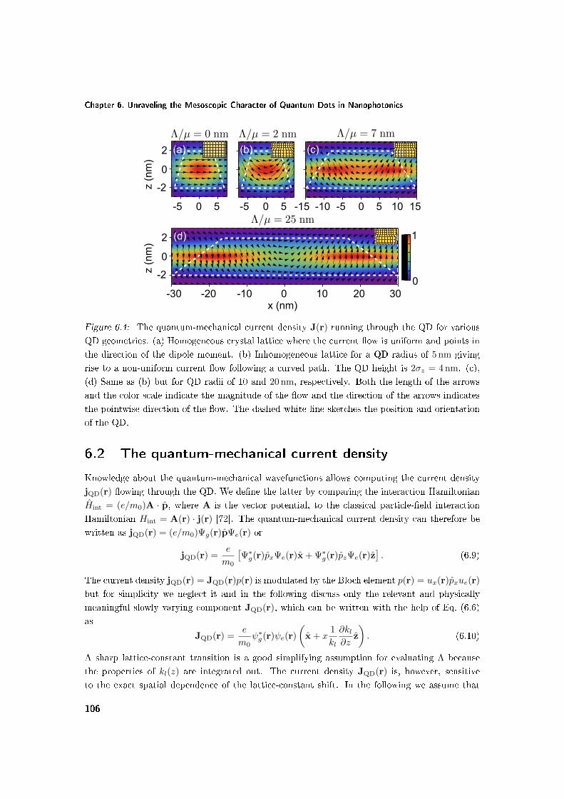
Chapter 6. Unraveling the Mesoscopic Character of Quantum Dots in Nanophotonics
-5 0 5
-2
0
2
0
1
-5 0 5 -5 0 5-10-15 10 15
0 10 20 30-10-20-30
-2
0
2
(a) (b) (c)
(d)
x (nm)
z (n
m)
z (n
m)
Figure 6.4: The quantum-mechanical current density J(r) running through the QD for various
QD geometries. (a) Homogeneous crystal lattice where the current ow is uniform and points in
the direction of the dipole moment. (b) Inhomogeneous lattice for a QD radius of 5 nm giving
rise to a non-uniform current ow following a curved path. The QD height is 2σz = 4 nm. (c),
(d) Same as (b) but for QD radii of 10 and 20 nm, respectively. Both the length of the arrows
and the color scale indicate the magnitude of the ow and the direction of the arrows indicates
the pointwise direction of the ow. The dashed white line sketches the position and orientation
of the QD.
6.2 The quantum-mechanical current density
Knowledge about the quantum-mechanical wavefunctions allows computing the current density
jQD(r) owing through the QD. We dene the latter by comparing the interaction Hamiltonian
Hint = (e/m0)A · p, where A is the vector potential, to the classical particle-eld interaction
Hamiltonian Hint = A(r) · j(r) [72]. The quantum-mechanical current density can therefore be
written as jQD(r) = (e/m0)Ψg(r)pΨe(r) or
jQD(r) =e
m0
[Ψ∗g(r)pxΨe(r)x + Ψ∗g(r)pzΨe(r)z
]. (6.9)
The current density jQD(r) = JQD(r)p(r) is modulated by the Bloch element p(r) = ux(r)pxue(r)
but for simplicity we neglect it and in the following discuss only the relevant and physically
meaningful slowly varying component JQD(r), which can be written with the help of Eq. (6.6)
as
JQD(r) =e
m0ψ∗g(r)ψe(r)
(x + x
1
kl
∂kl∂z
z
). (6.10)
A sharp lattice-constant transition is a good simplifying assumption for evaluating Λ because
the properties of kl(z) are integrated out. The current density JQD(r) is, however, sensitive
to the exact spatial dependence of the lattice-constant shift. In the following we assume that
106

Breakdown of the dipole theory at nanoscale proximity to a dielectric interface
most of the transition happens over two lattice constants as shown experimentally in Ref. [44].
Slowly varying Gaussian envelopes are used to model the QD wavefunctions ψg and ψe. In
QDs with a homogeneous crystal lattice ∂kl/∂z = 0 and thus vanishing mesoscopic moment
Λ = 0, the current density ows only along the direction of the dipole moment because there
are no gradients in the z-direction and the second term from the right-hand side of Eq. (6.9)
vanishes (see Fig. 6.4(a)). The presence of lattice inhomogeneities changes the ow dramatically
because strong gradients in the z-direction arise. The current density ows along a curved path
as illustrated in Figs. 6.4(b-d), conferring pronounced mesoscopic properties to QDs. The wider
the QD is, the sharper the transverse oscillations of the current are and the larger Λ/µ is. This
eect oers the possibility to enhance (diminish) the light-matter interaction by placing QDs
in environments where the electric vacuum eld exhibits gradients with the same (opposite)
sign, see also Fig. 6.1. We underline that the current density is an intrinsic property of QDs
and does not depend on the nanophotonic environment surrounding the QD. The current has a
spatial curvature that can be decomposed into a curl-free component, which probes the electric
eld in light-matter interactions, and a circular component, which probes the magnetic eld
of the electromagnetic quantum vacuum. The ability to eciently probe magnetic elds at
optical frequencies has been a long-sought goal in nanophotonics, and our ndings show that self-
assembled In(Ga)As QDs are the very rst quantum emitters that are not "blind" to the magnetic
eld of light. This topic is explored in detail in Chapter 7. The curved current density of QDs
opens new opportunities for designing ecient light-matter interfaces that exploit mesoscopic
eects to enhance the interaction with light. Aside from the local light-matter coupling strength,
other degrees of freedom could be potentially tailored by exploiting the mesoscopic interaction,
such as the photon-emission directionality or polarization.
6.3 Breakdown of the dipole theory at nanoscale proximity
to a dielectric interface
Deviations from the dipole theory have been observed in the proximity of a metal interface [26]
and were attributed to the strong plasmonic gradients that eciently probed the mesoscopic
character of QDs. In the present section we demonstrate deviations from the dipole theory in
the vicinity of an air interface, which is a weakly conning dielectric structure as pictured in
Fig. 6.1. Our ndings show that the mesoscopic strength Λ/µ of QDs is so large that even
dielectric environments may be used to tailor the multipolar radiation from QDs, which opens a
new and potentially unexplored dimension in the eld of cavity quantum electrodynamics.
Previous experiments reported the measurements of spontaneous-emission decay rates for
ensembles of QDs that are placed at dierent distances to a GaAs-air interface [84, 86]. Figure 6.5
displays the data that were used to reliably extract the dipole moment by exploiting the data
points recorded at distances above 75 nm [84]. A systematic deviation from the dipole theory
was found at distances below ∼ 75 nm, whose origin has been unclear and was speculated to be a
result of enhanced loss processes at the etched interfaces. Here we show that the deviations can
107

Chapter 6. Unraveling the Mesoscopic Character of Quantum Dots in Nanophotonics
0 100 200 300
0.9
1
1.1
1.2
1.3
1.4
Dec
ay r
ate
(ns−
1 )
0 100 200 300
0.9
1
1.1
1.2
1.3
1.4
z0
GaAs
Air
0 100 200 300
0.9
1
1.1
1.2
1.3
1.4
Dec
ay r
ate
(ns−
1 )
0 100 200 300
0.9
1
1.1
1.2
1.3
1.4
0 100 200 300
0.9
1
1.1
1.2
1.3
1.4
Distance to interface, z0
(nm)
Dec
ay r
ate
(ns−
1 )
0 100 200 300
0.9
1
1.1
1.2
1.3
1.4
Distance to interface, z0
(nm)
(a) (b)
(c) (d)
(e) (f)
E=1170 meV E=1186 meV
E=1204 meV E=1216 meV
E=1252 meV E=1272 meV
Figure 6.5: Observation of deviations from the dipole theory for QDs near an interface. (a)-(f)
Measured decay rates versus distance z0 to the GaAs-air interface (data points) at six dierent
energies E across the inhomogeneously broadened emission spectrum. The dipole (multipolar)
theory is indicated by the black dashed (blue solid) line. A refractive index n = 3.5 of GaAs was
used. The inset in (a) is a schematic illustrating the sample geometry.
be explained by the contributions from the mesoscopic moment Λ to the light-matter interaction
strength. We use the multipolar theory developed in Chapter 5 to analyze the experimental data
shown in Fig. 6.5(a). The decay rate beyond the dipole approximation can be decomposed into
108

Breakdown of the dipole theory at nanoscale proximity to a dielectric interface
ExpTheory
1.15 1.2 1.25 1.35
10
15
20
25
Energy (eV)
Λ/µ
(nm
)
(a) (b)
1.15 1.2 1.25 1.30
5
10
Energy (eV)L z
(c)
Height (nm)
Figure 6.6: Microscopic insight into the mesoscopic strength of QDs. (a) Extracted mesoscopic
strength Λ/µ over the emission spectrum of QDs (red squares) along with the prediction of the
theoretical model (blue dashed line) assuming that the QDs have a xed in-plane size and only
the height varies (see text for details). (b) Spectral dependence of the QD height as predicted by
the theoretical model, which agrees well with the atomic-force microscopy measurements from
(c). The data in (c) was published in Ref. [86].
three decay channels Γ = Γ(0) + Γ(1) + Γ(2) with
Γ(0)(r0) = Cµ2ImGxx(r0, r0)
Γ(1)(r0) = 2CΛµ ∂xImGzx(r, 0)|z=z0Γ(2)(r0) = CΛ2 ∂x∂
′xImGzz(r, r
′)|z=z′=z0 ,
(6.11)
where C = 2µ0/~. We set Λ and µ as free parameters and t the experimental data with the
resulting dependences plotted in Fig. 6.5 for all the emission energies. It should be mentioned
that a data point observed at a distance of 20 nm from the GaAs-air interface is not shown
in Fig. 6.5 and is omitted from the analysis because it shows a much higher decay rate and
lower photoluminescence intensity, which is likely to be caused by nonradiative tunneling of the
QD charge carriers to surface states [86]. A phenomenological distance-independent loss rate
is added to Γ to account for intrinsic nonradiative decay channels within the QD but is found
to be negligibly small in the present analysis. This procedure is used independently for every
emission energy resulting in the data points in Fig. 6.6(a). The dipole-theory t is performed
by setting Λ = 0 and excluding the rst six data points from the analysis. For completeness, we
plot distance-dependent decay rates for various mesoscopic strengths in Fig. 6.7. It can be seen
that both the amplitude and the phase of the oscillations are substantially aected at distances
less than ∼ 100 nm from the interface, which allows extracting the mesoscopic strength from
the experimental data. It is interesting to note that the eect is more dramatic for QDs ipped
upside down for which Λ/µ < 0 as indicated by the red curves in Fig. 6.7.
The multipolar theory quantitatively reproduces the functional dependence observed in the
experiment for all emission energies, see Fig. 6.5. The extracted mesoscopic strength Λ/µ in-
creases with emission energy and varies from 10 to 23 nm over the inhomogeneously broadened
emission spectrum, cf. Fig. 6.6(a), which reects a pronounced dependence on QD size. The
increase in Λ/µ with energy is successfully explained by our microscopic QD theory, which
is presented in the following. We use Eq. (6.7) to model the spectral dependence of Λ/µ in
109

Chapter 6. Unraveling the Mesoscopic Character of Quantum Dots in Nanophotonics
0 100 200 3000.7
0.8
0.9
1
1.1
Distance to interface, z0
(nm)
Nor
mal
ized
dec
ay r
ate
z0
GaAs
Air
10 nm 0 nm-10 nm-25 nm
25 nm
Figure 6.7: Calculated spontaneous-emission decay rates as a function of distance to a GaAs-air
interface for various mesoscopic strengths. The vanishing mesoscopic strength corresponds to
the dipole theory. The decay rates are normalized to the decay rate in homogeneous GaAs. A
refractive index n = 3.5 of GaAs and an emission wavelength of λ = 1µm were employed.
Fig. 6.6(a), where we employ several assumptions. First, only the height of QDs is assumed to
vary across the spectrum while the in-plane size remains constant. This assumption is supported
by studies of size and shape performed on self-assembled QDs [42], where a small relative distri-
bution of the in-plane QD size is observed. Second, we consider the inhomogeneously broadened
spectrum to be caused only by the random distribution of the size (and consequently of the
quantization/emission energy) of QDs. Other parameters such as strain distribution or chemical
composition are considered constant over the emission spectrum. Third, we assume that only
the height of the QDs contributes to the quantization energy, since atomic-force microscopy mea-
surements show that the height of self-assembled In(Ga)As is generally much smaller than the
in-plane size [44]. Fourth, we assume disk-shaped wavefunctions that can be decomposed into
in-plane Φ and out-of-plane φ components, i.e., ψ(r) = Φ(x, y)φ(z). With this, Eq. (6.7) can be
rewritten asΛ
µ= −∆al
al
⟨Φg∣∣x2∣∣Φe⟩
〈Φg|Φe〉φg(zT )φe(zT )
〈φg|φe〉. (6.12)
The rst term from the right-hand side denotes the relative change in the lattice constant while
the second and third terms contain the dependence on the in-plane QD size and QD height,
respectively. We nd the functional dependence, f , between the third term and the quantization
energy, E − E0, using a nite-potential-well model, where E is the emission energy and E0 the
bulk band gap of the QD material. We therefore obtain
Λ
µ= S × f(E − E0), (6.13)
where S = −(∆al/al)⟨Φg∣∣x2∣∣Φe⟩ / 〈Φg|Φe〉. The trend of the experimental data from Fig. 6.6(a),
i.e., that Λ/µ increases with energy, agrees very well with our model (see the theory curve in the
same gure), if the in-plane QD size is constant across the emission spectrum and only the height
110

Breakdown of the dipole theory at nanoscale proximity to a dielectric interface
varies. This behavior has been reported in the literature in studies of QD size and shape using
similar growth conditions as used here [42]. We note that if the QDs had a constant aspect ratio,
the mesoscopic strength would be predicted to decrease with energy because the eect depends
stronger on the in-plane QD size, cf. Eq. (6.8). Some degree of correlation between height and
width has been observed [175], but our study suggests that such correlations are small in our
sample. We also stress that our study deals with the in-plane size of the QD wavefunctions,
which generally can be dierent than the QD size measured by surface-prole techniques. We
use S and E0 as tting parameters and obtain a bulk band gap E0 = 1.13 eV of the QD, which
yields quantization energies ranging from 40 meV up to 140 meV across the emission spectrum.
The resulting curve in Fig. 6.6(a) agrees well with the experimental results. By mapping the
quantization energy to the QD size, we are able to extract a QD height that varies from 11 nm
to 3 nm across the inhomogeneously broadened spectrum, cf. Fig. 6.6(b), which agrees well with
the values obtained from atomic-force microscopy measurements presented in Fig. 6.6(c). We
conclude that QDs with larger emission energy have larger mesoscopic strengths because they are
shallow so that a large part of the excitonic wavefunction is aected by the lattice inhomogeneity.
The increase in the spontaneous-emission rate compared to the dipole theory for small dis-
tances to the interface is consistent with the behavior near a silver interface [26] and can be
understood with the help of Fig. 6.1. The nanophotonic environment breaks parity symmetry
and the vacuum eld is curved at the position of the QDs. This curvature is probed by the
inhomogeneous quantum-mechanical current density of QDs through the mesoscopic moment Λ
leading to enhanced light-matter interaction. Note that in the vicinity of a metal interface the
decay rate is diminished rather than enhanced because the plasmonic eld exhibits opposite cur-
vature. We exemplify such as scenario for the coupling to the plasmonic eld of a silver nanowire
with a radius of 20 nm and a refractive index nAg = 0.2+7i, which exhibits larger eld gradients
and mesoscopic eects are strongly enhanced, see Fig. 6.8. By matching the plasmonic eld to
the QD current pattern, the light-matter interaction can be drastically improved. The congura-
tion in Fig. 6.8(a) exhibits a substantial coupling enhancement to surface plasmons compared to
a point dipole (from 75 % to 90 %), cf. Fig. 6.8(c). In contrast, the interaction is diminished by
ipping the QD, cf. Fig. 6.8(b), because the ows of the QD current and of the environment are
spatially orthogonal. In other words, µ and Λ interfere constructively in (a) and destructively
in (b). These ndings open the prospect of the realization of ecient nanophotonic designs for
harvesting the mesoscopic nature of QDs.
111

Chapter 6. Unraveling the Mesoscopic Character of Quantum Dots in Nanophotonics
0 20
0
10
20
-20x (nm)
0
10
20
(a)
β pl
z0
z0 (nm)20100
0
0.2
0.4
0.6
0.8
1 (c)
0
1
(b)
z (n
m)
Figure 6.8: Quantum dots coupled to surface plasmons of a silver nanowire. The curved
quantum-mechanical current density of QDs probes the complex eld prole of the nanowire
as exemplied in (a). Since the eld matches the curvature of the QD current, the coupling
eciency βpl to surface plasmons is enhanced, red curve in (c), beyond that of a point dipole,
dashed curve in (c). (b) A QD ipped upside down exchanges energy less eciently with the
plasmonic eld as shown in (c) by the blue line. In (a)-(b), both the length of the arrows and
the color scale denote the magnitude of the vector eld.
6.4 Lattice-distortion eects beyond the multipolar theory
As shown earlier, the lattice distortion generates an inhomogeneous quantum-mechanical current
density owing through QDs. This eect results in two multipolar moments being signicant
for QDs: the dipole moment µ and the mesoscopic moment Λ. While the multipolar theory
of spontaneous emission developed in the present thesis readily accounts for these eects, the
question arises of how these eects can be incorporated in an exact formalism that does not
perform the multipolar expansion but rather treats the full nonlocal character of the light-matter
interaction beyond the dipole approximation from Eq. (5.3), which we rewrite for convenience
Γ(ω) =2µ0
~
∫ ∫d3rd3r′Im
[j(r) ·
←→G (r, r′) · j∗(r′)
].
Such a nonlocal formalism was developed earlier [83] but does not account for the lattice dis-
tortion occurring in the QD and treats only the mesoscopic QD potential as a source for the
dipole-approximation breakdown. Generalizing this formalism can be done using the presently
developed theory that evaluates the current distribution owing through the QD. Inserting
Eq. (6.10) into the above equation leads to a generalized and exact-to-all-orders expression for
112

Summary
the spontaneous-emission rate beyond the dipole approximation
Γ(ω) =2µ0 |pcv|2
~
[∫ ∫d3rd3r′Im [Jx(r)Gxx(r, r′)J∗x(r′)]
+2Re
(∫ ∫d3rd3r′Jx(r)ImGxz(r, r
′)J∗z (r′)
)+
∫ ∫d3rd3r′Im [Jz(r)Gzz(r, r
′)J∗z (r′)]
], (6.14)
where Jx(r) = x · JQD(r) = (e/m0)ψ∗g(r)ψe(r) and Jz(r) = z · JQD(r) = xk−1l (∂kl/∂z)Jx are
the x- and z-projections of the QD current density JQD(r), respectively. The rst term from the
right-hand side is identical to the expression derived in Ref. [83] and its zeroth-order expansion
contains the electric-dipole contribution Γ(0). The second an third terms are generated by the
transverse oscillations of the current density JQD(r) and contain the rst Γ(1) and second Γ(2)
order contributions, respectively. Due to the odd x-operator present in the transverse current
density Jz(r), which is a consequence of the transverse ow changing direction along x, the
second and third terms vanish in the dipole approximation and only the rst terms survives.
Equation (6.14) is the most general expression for the spontaneous emission of light from QDs
beyond the dipole approximation and should be preferred over the multipolar theory when the
gure of merit k × Λ/µ > 1, i.e., when the multipolar expansion diverges. Such a scenario is
however hard to achieve in practice because even the largest QDs grown so far are still small
compared to the wavelength of light λ/2π.
6.5 Summary
We have developed a novel microscopic model that successfully explains the large mesoscopic
strengths of In(Ga)As QDs observed experimentally. We nd the eect to be governed by the
lack of symmetry of the nanoscopic crystal lattice and scaled by the extended mesoscopic size of
the QD. The microscopic current density oscillates along a non-trivial curved path and can be
expressed as a superposition between the electric dipole and the mesoscopic moment of the QD.
This mesoscopic current is generated at the unit-cell level in analogy to the generation of currents
in macroscopic systems. Our work deepens the physical understanding of semiconductor QDs
and we therefore expect it to be of signicance for the active elds of solid-state quantum elec-
trodynamics and quantum-information processing, where ecient quantum interfaces between
QDs and light are exploited.
113


Chapter 7
Probing Electric and Magnetic
Vacuum Fluctuations with
Quantum Dots
Spontaneous emission is a fundamental physical process, which plays an essential role in nature
as the main source of optical radiation, and in applications as the principal source of articial
illumination. Be it the radiation from the sun or the indoor lighting, spontaneous emission
plays a paramount role in our lives and in the life of living organisms. At the heart of the
spontaneous-emission process lays the uctuating electromagnetic vacuum eld, which perturbs
quantum emitters and triggers their radiative decay. The electric and magnetic elds comprising
the vacuum eld are intimately connected through Maxwell's equations and do not exist without
one another. Despite being equally important for generating the electromagnetic eld, there is
a fundamental built-in asymmetry in their interaction with matter. Specically, the magnetic
force acting on a charged particle moving with velocity v is v/c times smaller than the electric
force. Only in environments where charges move extremely fast, such as charged plasmas [176],
do magnetic interactions become important.
The aforementioned asymmetry is inherited by the spontaneous emission of light from quan-
tum emitters, where magnetic and other higher-order multipole eld components do not play
normally a role. This is because the variation of the electromagnetic eld is negligible over the
spatial extent of most quantum emitters, which has rendered the dipole approximation a highly
successful approximation in quantum electrodynamics. Nevertheless, magnetic-dipole (MD) and
electric-quadrupole (EQ) transitions are well known in atomic physics and can be accessed with
light despite being much weaker [177179], since they have dierent selection rules than electric-
dipole (ED) transitions [158, 159, 180]. Self-assembled QDs are fundamentally dierent and the
dipole approximation may not apply to QDs even on dipole-allowed transitions, as was observed
experimentally in Refs. [26, 162] and discussed in Chapters 5 and 6. The asymmetry of the QD
wavefunctions originating from a lack of mirror-reection symmetry (parity symmetry) of the
115

Chapter 7. Probing Electric and Magnetic Vacuum Fluctuations with Quantum Dots
Figure 7.1: Schematic of the physical system studied in the present chapter. The QD has
three decay channels in the proximity of a metal interface: radiative ΓRAD, coupling to surface
plasmons ΓSP and ohmic losses heating the metal ΓLS. The electron (blue) and hole (red)
wavefunctions illustrate the built-in asymmetry of the QD. The Cartesian coordinate system is
indicated accordingly.
QD connement potential breaks the usual selection rules applicable in atomic physics leading
to a curved quantum-mechanical current density owing through QDs with both ED and mul-
tipolar contributions on the same transition. For atoms a related but very weak asymmetry
is induced by the electroweak interaction and has been used to probe the standard model of
particle physics [181]. In contrast, the parity violation is very strong for QDs due to their asym-
metric structure and, therefore, they may be exploited as a probe of the parity of the photonic
nanostructure or the nature of the multipolar quantum-vacuum uctuations.
In the present chapter, we show that the commonly used self-assembled In(Ga)As QDs are
sensitive to both electric and magnetic elds, which is a consequence of large circular quantum-
mechanical current densities running through QDs [164], and has resulted in the publication of
Ref. [162]. The multipolar eects explained by our theory are relevant and important in many
nanophotonic congurations. A current hot topic in nanophotonics exploits the role of non-
locality of the dielectric response in plasmonics [182, 183]. Here we study a dierent non-local
phenomenon by accounting for the spatial extent and symmetry of QDs and their interaction
with the complex eld proles found in nanostructures of importance for photon emission. The
eect is particularly pronounced, if the nanophotonic environment violates parity symmetry. For
concreteness we consider the QD spontaneous emission for two experimentally realistic nanopho-
tonic structures: a semiconductor-metal plane interface and a plasmonic nanowire, see Fig. 7.1
for a sketch of the investigated geometry. We note that our results apply to self-assembled QDs
while, e.g., spherical nanocrystals would not possess the required symmetry. Our study demon-
strates that single QDs can be employed for locally probing complex photonic nanostructures
116

Electric and magnetic light-matter interaction
that tailor both the electric and magnetic eld [184, 185]. Sensitivity to the magnetic eld has
been a long-sought goal in nanophotonics, and has been achieved so far only by scanning near-
eld spectroscopy [186] where the disturbance of the electromagnetic eld prole by the applied
near-eld probe can be an issue. The nanometer-size of single QDs enables non-invasive probing
that operates at the single-electron single-photon level. Furthermore, the multipolar coupling
of QDs can potentially be exploited for enhancing the light-matter interaction with immediate
applications to quantum light sources for quantum-information processing [22].
7.1 Electric and magnetic light-matter interaction
In this section we show that QDs probe electric and magnetic elds simultaneously and eciently.
The present analysis concentrates on the rate of spontaneous emission Γ of the QD because it
is a direct and experimentally relevant measure of the light-matter coupling strength [57, 166].
Another interesting property would be the emission pattern of the QD that can be modied
and tailored by the interference of dipolar and multipolar contributions [179]. In contrast, the
multipolar eects discussed here do not aect the QD interaction with phonons, an essential
dephasing mechanism, since the phonon interaction depends mainly on the QD volume rather
than symmetry. It should be mentioned that the mesoscopic terms do not inuence the photon
statistics of the source, i.e., the excellent single-photon purity observed for QD sources prevails
also under conditions where mesoscopic contributions are signicant.
As the starting point, we use the multipolar theory of spontaneous emission developed in
Chapter 5, where it is shown that QDs have two degrees of freedom while interacting with light,
namely the dipole moment µ = µx and the mesoscopic moment←→Λ = Λxz. One single parameter,
Λ = 〈Ψg |xpz|Ψe〉, describes the light-matter interaction beyond the dipole approximation. The
ratio |Λ/µ| quanties the mesoscopic strength of the QD and was measured to vary between
10 nm and 20 nm over the emission spectrum of standard self-assembled In(Ga)As QDs [26, 164].
A conservative value of 10 nm will be used throughout the present analysis. The interaction
with light can be either suppressed or enhanced by the mesoscopic moment Λ depending on
the properties of the environment of the QD. This eect is illustrated in Fig. 7.3(a), where the
emission rate of a QD in the proximity of a silver interface is shown (at an emission wavelength
of 1000 nm and with the refractive indices of GaAs nGaAs = 3.42 and of silver nAg = 0.2 + 7i). A
QD and a point dipole exhibit dierent functional dependencies to the metal interface because
the former couples also to eld gradients while the latter does not, as is shown in the following.
Note that, unlike QDs, atomic wavefunctions possess parity symmetry so that µ and←→Λ never
contribute simultaneously.
As argued in Chapter 5, we expand the decay rate up to the second order Γ ' Γ(0) +
Γ(1) + Γ(2). In the proximity of metals, the QD can decay into propagating photons with the
rate ΓRAD, propagating surface plasmons (ΓPL), or ohmic-lossy modes in the metal (ΓLS) [187],
see Fig. 7.1. The former coupling to radiative modes is essentially not aected by multipolar
eects since the responsible electromagnetic eld varies weakly in space, i.e., ΓRAD ≈ Γ(0)RAD. In
contrast, the plasmon eld varies strongly and therefore multipolar eects inuence the excitation
117

Chapter 7. Probing Electric and Magnetic Vacuum Fluctuations with Quantum Dots
+ _
(b)
+ _(b)
+ _(c)
+ _+_
+ _+_(d)
Figure 7.2: Electric and magnetic light-matter interaction with mesoscopic QDs. (a) Light-
matter interaction processes governing Γ(0), where the ED interacts with the radiation modes of
the electric vacuum ERADx and the guided surface plasmon modes Ex. (b) Processes governing
the ED-MD interference. The light emitted by the ED µx interacts with the MD my and creates
a magnetic eld. The physical picture of Γ(1Q) is conceptually analogous and is presented in (c).
(d) Processes governing Γ(2) with pure MD and EQ contributions. The EQ Qxz couples to the
gradient of the electric vacuum.
rate of plasmons. The lossy modes are proportional to the imaginary part of the dielectric
permittivity [188] and raise the entropy of the system [189]. The coupling to lossy modes is
normally negligible for distances larger than ∼ 20 nm from the metal and we do not discuss them
further. We thus obtain the three light-matter interaction channels for mesoscopic QDs
Γ(0) = A |µ|2 ImGxx(0, 0) = ΓRAD + Γ(0)PL,
Γ(1) = 2ARe [Λµ∗] ∂xImGzx(r, 0)|r=0 ≈ Γ(1)PL,
Γ(2) = A |Λ|2 ∂x∂′xImGzz(r, r′)|r=r′=0 ≈ Γ
(2)PL,
(7.1)
where A = 2µ0/~. Each order has a clear physical meaning as explained below, where we
exemplify a semiconductor-silver interface as sketched in the inset of Fig. 7.3(a).
The zeroth-order rate, Γ(0), is the well-known ED contribution, and is given as a product of
a eld term, ImGxx, which is proportional to the (electric) LDOS, and a QD term, |µ|2, whichis proportional to the (electric) oscillator strength [72]. Here, a microscopic polarization in the
x-direction couples to the x-polarized electric eld, which probes the environment and interferes
118
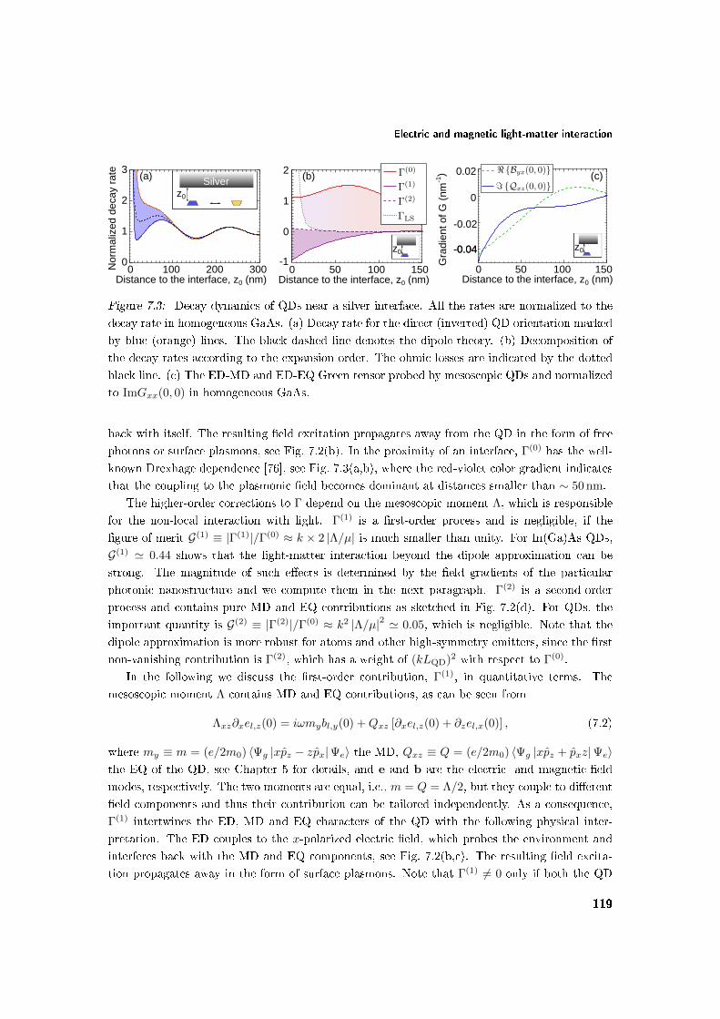
Electric and magnetic light-matter interaction
z0
Silver
0 100 200 3000
1
2
3
DistanceGtoGtheGinterface,Gz0G(nm)
Nor
mal
ized
Gde
cayG
rate (a)
DistanceGtoGtheGinterface,Gz0G(nm)0 50 100 150
-1
0
1
2
z0
(b)
Gra
dien
tGofGG
G(nm
-1)
0G 50 100 150DistanceGtoGtheGinterface,Gz0 (nm)
-0.04-0.04
0
-0.02
0.02 (c)
z0
Figure 7.3: Decay dynamics of QDs near a silver interface. All the rates are normalized to the
decay rate in homogeneous GaAs. (a) Decay rate for the direct (inverted) QD orientation marked
by blue (orange) lines. The black dashed line denotes the dipole theory. (b) Decomposition of
the decay rates according to the expansion order. The ohmic losses are indicated by the dotted
black line. (c) The ED-MD and ED-EQ Green tensor probed by mesoscopic QDs and normalized
to ImGxx(0, 0) in homogeneous GaAs.
back with itself. The resulting eld excitation propagates away from the QD in the form of free
photons or surface plasmons, see Fig. 7.2(b). In the proximity of an interface, Γ(0) has the well-
known Drexhage dependence [76], see Fig. 7.3(a,b), where the red-violet color gradient indicates
that the coupling to the plasmonic eld becomes dominant at distances smaller than ∼ 50 nm.
The higher-order corrections to Γ depend on the mesoscopic moment Λ, which is responsible
for the non-local interaction with light. Γ(1) is a rst-order process and is negligible, if the
gure of merit G(1) ≡ |Γ(1)|/Γ(0) ≈ k × 2 |Λ/µ| is much smaller than unity. For In(Ga)As QDs,
G(1) ' 0.44 shows that the light-matter interaction beyond the dipole approximation can be
strong. The magnitude of such eects is determined by the eld gradients of the particular
photonic nanostructure and we compute them in the next paragraph. Γ(2) is a second-order
process and contains pure MD and EQ contributions as sketched in Fig. 7.2(d). For QDs, the
important quantity is G(2) ≡ |Γ(2)|/Γ(0) ≈ k2 |Λ/µ|2 ' 0.05, which is negligible. Note that the
dipole approximation is more robust for atoms and other high-symmetry emitters, since the rst
non-vanishing contribution is Γ(2), which has a weight of (kLQD)2 with respect to Γ(0).
In the following we discuss the rst-order contribution, Γ(1), in quantitative terms. The
mesoscopic moment Λ contains MD and EQ contributions, as can be seen from
Λxz∂xel,z(0) = iωmybl,y(0) +Qxz [∂xel,z(0) + ∂zel,x(0)] , (7.2)
where my ≡ m = (e/2m0) 〈Ψg |xpz − zpx|Ψe〉 the MD, Qxz ≡ Q = (e/2m0) 〈Ψg |xpz + pxz|Ψe〉the EQ of the QD, see Chapter 5 for details, and e and b are the electric- and magnetic-eld
modes, respectively. The two moments are equal, i.e., m = Q = Λ/2, but they couple to dierent
eld components and thus their contribution can be tailored independently. As a consequence,
Γ(1) intertwines the ED, MD and EQ characters of the QD with the following physical inter-
pretation. The ED couples to the x-polarized electric eld, which probes the environment and
interferes back with the MD and EQ components, see Fig. 7.2(b,c). The resulting eld excita-
tion propagates away in the form of surface plasmons. Note that Γ(1) 6= 0 only if both the QD
119

Chapter 7. Probing Electric and Magnetic Vacuum Fluctuations with Quantum Dots
wavefunctions and the electromagnetic environment violate parity symmetry. This is because a
parity-symmetric electronic potential cannot be both µ- and←→Λ -allowed, and a parity-symmetric
environment contains either even or odd electromagnetic modes. The ED is an even operator and
would couple only to the even modes, while Λ corresponds to an odd operator and would couple
to the odd modes inducing no mutual interference between µ and Λ and a vanishing Γ(1). The
rst-order contribution can both enhance and suppress the light-matter interaction depending
on whether the light emitted by the ED µ interferes constructively or destructively with the
mesoscopic moment Λ. This can be seen in Fig. 7.3(a), where by ipping the QD orientation
Λ changes sign and, hence, Γ(1) changes from suppressing to enhancing the decay rate. The
multipolar contribution to Γ(1) is
Γ(1) = Γ(1m) + Γ(1Q)
= Aωmyµ∗ReByx(0, 0) +AQxzµ
∗ImQxz(0, 0),(7.3)
where we dene the ED-MD Green tensor Byx(0, 0) = −iω−1 [∂xGzx(r, 0)− ∂zGxx(r, 0)]r=0, the
ED-EQ Green tensor Qxz(0, 0) = [∂xGzx(r, 0) + ∂zGxx(r, 0)]r=0, and assume Λµ∗ to be real,
which holds in the eective-mass approximation in the absence of applied magnetic elds. Equa-
tion (7.3) shows that QDs access the magnetic and electric-quadrupole vacuum elds, similarly to
the way dipoles probe the electric component of the vacuum, and is demonstrated in Fig. 7.3(c),
where the contribution of ReByx(0, 0) and ImQxz(0, 0) is shown. The two components of the
Green tensor vary over length scales of tens of nanometers, which is comparable to the QD
size [44] and demonstrates that QDs are ecient probes of electric and magnetic elds on the
same electronic transition. In the following, we show that this novel property of QDs can be
used to probe the parity symmetry of complex nanophotonic environments.
7.2 Probing the parity symmetry of nanophotonic environ-
ments
Quantum dots interact with light as spatially extended objects and are therefore capable of
probing not only the electric-eld magnitude at their position but also eld variations. This is
the basic property allowing to use QDs for probing the complex nature of the electromagnetic
vacuum uctuations. If placed in an unknown nanophotonic structure, the spontaneous-emission
rate of the QD is generally given by ΓN ≈ Γ(0)N + Γ
(1)N . By ipping the QD orientation, which is
a feasible experimental procedure that can be done by etching away the substrate [26], the ED
contribution is the same but the rst-order term has opposite symmetry and changes sign, i.e.,
ΓH ≈ Γ(0)H +Γ
(1)H = Γ
(0)N −Γ
(1)N . As a consequence, both the projected Green tensor ImGxx(0, 0)
and the spatial gradient ∂xImGzx(0, 0) can be unambiguously extracted, cf. Eq. (7.1). While
the former corresponds to the electric-eld strength generated by an ED at the position of the
emitter, the latter describes the electric-eld gradient generated by the same ED. We exemplify
this aspect by investigating the interaction between QDs and surface plasmons in the proximity of
a silver nanowire (radius ρ = 30 nm), which is capable of collecting most of the QD emission into
120

Probing the parity symmetry of nanophotonic environments
R0sxnm)0 10 20 30 40
02468
10
02468
10
Silver
R0
Silver
R0
xa)
xd)
Nor
mal
ized
sde
cays
rate
Pro
ject
edsG
reen
Msste
nsor
02468
10
02468
10
0 10 20 30 40
xc)
xf)
rz
10
15
20
25
30
0 10 20-10-2010
15
20
25
30D
ista
nces
tosn
ano
wire
sxnm
)
xb)
xe)
R0sxnm)zsxnm)
Min
Max
Figure 7.4: Probing eld gradients with mesoscopic QDs. (a) For an axially-oriented dipole,
Γ(1) enhances (suppresses) the light-matter interaction for the conguration marked by orange
(blue). The dashed line is the prediction of the dipole theory. (b) Vector plot of the plasmonic
eld generated by the ED of the QD situated 20 nm away from the nanowire. Both the length of
the arrows and the color scale denote the eld magnitude. The white arrow inside the QD shows
the ow of the quantum-mechanical current inside the QD. (c) The eld projections probed by
the QD can be extracted by subtracting the decay curves in (a). The gray-shaded area is the
region where nonradiative losses are dominant. (d) For a radially-oriented dipole, Γ(1) = 0 and
the QD behaves as an electric dipole.
a single propagating eld mode, an important goal in the eld of quantum photonics [22, 188].
We nd the nanowire to support a single strongly conned plasmon mode with G(1) = kSP ×2 |Λ/µ| = 0.76 [72, 188] leading to stronger eld gradients than for the plane silver interface. The
contribution of Γ(2) is again negligible since G(2) = 0.14. The coupling to radiation and lossy
modes is modelled as a point-dipole in the simple quasi-static approximation [188, 190], which
gives excellent agreement with the full electrodynamic computation [191]. The Green tensor of
the plasmon eld acquires a particularly simple form [191] and for the geometry presented in
Fig. 7.4(a) the relevant rates read
Γ(0)PL
Γ(0)GaAs
= C |fz(0)|2 (7.4)
Γ(1)PL
Γ(0)GaAs
= 2CΛ
µRe [∂zf∗r (0)] fz(0) , (7.5)
where C = 3πc0ε0/nk20vg, vg is the group velocity of the guided mode and the decay rates have
been normalized to the decay rate in homogeneous GaAs. Equations (7.47.5) contain the two
eld components, which can be probed by QDs in spontaneous-emission experiments, as shown
in the following.
In order to acquire an understanding of the sensing capability of QDs, we analyze the prop-
121
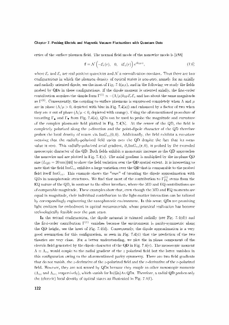
Chapter 7. Probing Electric and Magnetic Vacuum Fluctuations with Quantum Dots
erties of the surface-plasmon eld. The normal eld mode of the nanowire mode is [188]
f = N(−Er(r), 0, iEz(r)
)eikSPz, (7.6)
where Er and Ez are real positive quantities and N a normalization constant. Thus there are two
congurations in which the plasmon density of optical states is non-zero, namely for an axially
and radially oriented dipole, see the inset of Fig. 7.4(a,c), and in the following we study the elds
probed by QDs in these congurations. If the dipole moment is oriented axially, the rst-order
contribution acquires the simple form Γ(1) ∝ −(Λ/µ)kSPErEz and has about the same magnitude
as Γ(0). Consequently, the coupling to surface plasmons is suppressed completely when Λ and µ
are in phase (Λ/µ > 0, depicted with blue in Fig. 7.4(a)) and enhanced by a factor of two when
they are π out of phase (Λ/µ < 0, depicted with orange). Using the aforementioned procedure of
recording ΓN and ΓH from Fig. 7.4(a), QDs can be used to probe the magnitude and curvature
of the complex plasmonic eld plotted in Fig. 7.4(b). At the center of the QD, the eld is
completely polarized along the z-direction and the point-dipole character of the QD therefore
probes the local density of states via ImGzz(0, 0). Additionally, the eld exhibits a curvature
meaning that the radially-polarized eld varies over the QD despite the fact that its mean
value is zero. This radially-polarized axial gradient, ∂zImGrz(r, 0), is probed by the extended
mesoscopic character of the QD. Both elds exhibit a monotonic increase as the QD approaches
the nanowire and are plotted in Fig. 7.4(c). The axial gradient is multiplied by the in-plane QD
size (LQD = 20 nm)[44] to show the eld variation over the QD spatial extent. It is interesting to
note that the eld ImGrz exhibits a large variation over the QD that is comparable to the probed
eld itself ImGzz. This example shows the "ease" of breaking the dipole approximation with
QDs in nanophotonic structures. We nd that most of the contribution to Γ(1)PL stems from the
EQ nature of the QD, in contrast to the silver interface, where the MD and EQ contributions are
of comparable magnitude. These examples show that, even though the MD and EQ moments are
equal in magnitude, their individual contribution to the light-matter interaction can be tailored
by correspondingly engineering the nanophotonic environment. In this sense, QDs are promising
light emitters for embedment in optical metamaterials, whose practical realization has become
technologically feasible over the past years.
In the second conguration, the dipole moment is oriented radially (see Fig. 7.4(d)) and
the rst-order contribution Γ(1) vanishes because the environment is parity-symmetric along
the QD height, see the inset of Fig. 7.4(d). Consequently, the dipole approximation is a very
good assumption for this conguration, as seen in Fig. 7.4(d) that the prediction of the two
theories are very close. For a better understanding, we plot the in-phase component of the
electric eld generated by the dipole character of the QD in Fig. 7.4(e). The mesoscopic moment
Λ ≡ Λrz would couple to the radial gradient of the z-polarized eld but the latter vanishes in
this conguration owing to the aforementioned parity symmetry. There are two eld gradients
that do not vanish, the z-derivative of the z-polarized eld and the r-derivative of the r-polarized
eld. However, they are not sensed by QDs because they couple to other mesoscopic moments
(Λzz and Λrr, respectively), which vanish for In(Ga)As QDs. Therefore, a radial QD probes only
the (electric) local density of optical states as illustrated in Fig. 7.4(f).
122

Summary
7.3 Summary
We have shown that the commonly employed In(Ga)As QDs are capable of strongly interacting
with the multipolar quantum vacuum on dipole-allowed transitions. This striking behavior is
triggered by the lack of parity-symmetry of the electronic wavefunctions in the growth direction,
a feature that is absent in atomic physics because atoms have parity symmetry. The rst-order
expansion term Γ(1) can be comparable in magnitude to the dipole rate Γ(0) in nanophotonic
structures. This eect can be exploited to use QDs as a probe of the local eld environment
revealing not only information about the eld itself but also about its gradients. Furthermore,
by engineering the nanophotonic environment it is possible to selectively access the MD or EQ
nature of the QD and, thereby, to tailor the multipolar radiation of semiconductor QDs. We
have exemplied this for metal nanostructures but any strongly- or rapidly-varying optical modes
would produce deviations from the dipole approximation and we therefore expect this work to
be of signicance not only for plasmon-based devices [192] and photovoltaics [193], but also for
the active eld of photonic-crystal cavities and waveguides, where QDs have been described as
dipole emitters so far.
123


Chapter 8
Conclusion & Outlook
The present thesis has explored fundamental aspects of the optical properties of quantum dots.
The size, shape and material composition of quantum dots can be accurately engineered, which
oers precise control over their properties, in particular over the interaction with light. As a
consequence of their mesoscopic nature, quantum dots are fundamentally dierent from atomic
emitters in many respects.
One such example concerns the strength of the light-matter coupling, which can be tuned
over orders of magnitude depending on the quantum-dot size and geometry. This has been
demonstrated in the present work by measuring single-photon superradiance in a monolayer-
uctuation quantum dot. The tens of thousands of atoms comprising the quantum dot oscillate
in unison leading to a "giant" light-matter coupling. The latter is a manifestation not only of
the mesoscopic size of quantum dots but also of the underlying fermionic nature of the quantum-
dot excitation, which builds strong spatial correlations within the quantum dot. This eect is
expected to be of signicance for applications beneting from a large light-matter interaction at
the nanoscale, such as cavity quantum electrodynamics exploring strong coupling between light
and matter, one-dimensional waveguides where quantum dots induce strong interactions between
individual photons, as well as solid-state optoelectronic devices including solar cells, nano-lasers
and light-emitting diodes. An extraordinary challenge in quantum photonics pertains to the
creation of coherent quantum bits, and monolayer-uctuation quantum dots may provide a solu-
tion to the challenge owing to their fast radiative decay, which is likely to outspeed decoherence
processes. To this end, exploiting these quantum dots as an ecient interface between stationary
and ying quantum bits is a particularly attractive prospect for quantum-information science.
If the mesoscopic nature of quantum dots is combined with a lack of parity symmetry of
the underlying wavefunctions, the interaction with light can be further enriched. In particular,
we have shown that self-assembled In(Ga)As quantum dots are nanoscale probes of electric and
magnetic elds on a single optical transition, an eect unknown to the parity-symmetric atomic
emitters. This is caused by distortions at the level of the crystal lattice that forms the quantum
dot. The resulting quantum-mechanical current density owing through the quantum dot has
a pronounced circular character and explains the microscopic origin of the magnetic moment of
125

Chapter 8. Conclusion & Outlook
e h
e h
he
Excitonplocalization Currentpdensity
Self6assembledInOGa:AspQDs
Monolayer6fluctuationGaAspQDs
Droplet6epitaxyGaAspQDs
~15pnm
~4
pnm
~30pnm
~20pnm~
4pn
m~
4pn
m
OS:p10615QE:p806953
OS:p606100QE:p906993
OS:p8610QE:p706803
Figure 8.1: Synthesis of the electronic and optical properties of the three classes of quantum
dots explored in the present thesis. The red, blue and green envelopes denote the hole, electron
and exciton wavefunction, respectively. The pointwise direction and magnitude of the quantum-
mechanical current owing through quantum dots are denoted by the direction and length of
the white arrows, respectively. The oscillator strength (OS) and quantum eciency (QE) are
indicated accordingly.
quantum dots. Extensive eorts have been devoted to achieve sensitivity to the magnetic eld
of light. To this end, satisfactory results have been achieved so far only in optical metamaterials
and in the near eld of plasmonic structures. Quantum dots provide their quantum nature as an
extended degree of freedom, and the lack of ohmic loss as an intrinsic advantage for obtaining
magnetic sensitivity at optical frequencies.
Yet another complexity arising in solid-state environments pertains to the manifestation of
nonradiative processes. Defect impurities in the vicinity of quantum dots may trap one of the
charge carriers constituting the exciton and thus lower the eciency of radiative recombination.
We have measured an excellent near-unity quantum eciency of monolayer-uctuation quantum
dots, which is likely due to the ultra-clean growth procedure of these quantum dots. In contrast,
it was found that droplet-epitaxy quantum dots have a relatively modest quantum eciency of
about 75 %.
In the present thesis we have studied three dierent classes of quantum dots and we summarize
their properties in Fig. 8.1. Self-assembled In(Ga)As quantum dots have a prominent lattice-
constant shift inducing a curved quantum-mechanical current density with both electric and
magnetic character. The chemical gradient along the height of these quantum dots results in a
displacement of electrons and holes generating a static dipole moment. In monolayer-uctuation
126

quantum dots, the electron and the hole build spatial correlations within the extended exciton
wavefunction leading to a strongly and superradiantly enhanced light-matter interaction. The
large physical size of droplet-epitaxy quantum dots is not reected by the small spatial extent
of the exciton wavefunction. This is likely caused by material intermixing between the droplet-
epitaxy quantum dot and the surrounding matrix during the growth process.
The research carried out in the present study opens three major prospects for the further
development of science and technology. The rst prospect pertains to achieving unprecedented
enhancement of light-matter interaction at the nanoscale exploiting the eect of single-photon su-
perradiance. The superradiant enhancement can potentially be orders-of-magnitude larger than
the experiments reported here. This can be achieved in yet larger quantum dots and calculations
show [83] that a hundred-fold enhancement is realistically achievable in monolayer-uctuation
quantum dots with a radius of about 50 nm. This would correspond to a quantum dot that is
suciently large to build strong superradiant eects, yet suciently small to be in the Dicke
regime with constructive cooperativity in which the dipole approximation is valid. Due to the
weak quantum connement present in such large quantum dots, working at millikelvin temper-
atures would be crucial for preparing only the relevant 1s state of the exciton manifold. The
incorporation of such quantum dots in photonic structures beneting from large Purcell factors
such as nanocavities and waveguides may propel the generation speed of single photons to the
terahertz regime yielding remarkably large radiating powers of hundreds of nanowatts from a
single quantum emitter. The single photons emitted from a large quantum dot would potentially
be highly coherent, partly due to an intrinsically weaker coupling to nuclear spin noise [107]
and phonon dephasing [127] for large excitons, partly because the dephasing mechanisms present
in solid-state environments would be largely negligible compared to a radiative decay at sub-
picosecond time scales. Even faster radiative decays could be achieved in materials with large
Rydberg energies [194, 195]. This may allow studying energy non-conserving eects such as
the ultrastrong coupling regime of cavity quantum electrodynamics for the rst time at optical
frequencies. Another intriguing aspect is that the collective Lamb shift has been predicted to
be nite [108] without the renormalization schemes required in the quantum electrodynamics of
conventional emitters.
The second prospect is related to the inhomogeneous quantum-mechanical current density
owing through quantum dots. So far, only the dipole moment of In(Ga)As quantum dots has
been exploited in photonic nanostructures. We have shown, however, that the complex nature
of the quantum-mechanical current generates an additional optical degree of freedom, the meso-
scopic moment, which may play an important role in light-matter interactions. To this end, the
realization of nanostructures that tailor both the dipole and the mesoscopic nature of quantum
dots is a particularly attractive prospect that will likely lead to enhanced emission eciency. Such
a scenario can be readily realized in plasmonic systems with lack of parity symmetry and strong
eld gradients. For instance, the proposal for ultrastrong Purcell enhancement from Ref. [165]
tailors the out-of-plane dipole moment of quantum emitters but is incompatible with the in-
plane dipole of conventional quantum dots. The large mesoscopic moment of In(Ga)As quantum
dots may oer a solution by probing the strong out-of-plane eld gradients of the plasmonic
127

Chapter 8. Conclusion & Outlook
nanoparticle.
The third prospect concerns employing quantum dots as the building blocks of a quantum
metamaterial, a fundamentally new medium that combines the fascinating phenomena related
to classical metamaterials such as negative index of refraction, super-lensing and cloaking, with
the quantum nature of quantum dots that operate at the single-electron and single-photon level.
This is possible because the quantum-mechanical current owing through In(Ga)As quantum
dots is curved and resembles the current density running through split-ring resonators, the
building blocks of conventional metamaterials. An intrinsic limitation of split-ring resonators
is the ohmic loss of the underlying metal structure, which renders conventional metamaterials
extremely lossy and futile for practical applications. In particular, the largest measured propaga-
tion length of light in metamaterials is about 1 µm [196]. In contrast, quantum dots do not have
such a thermodynamically irreversible loss channel and could operate with signicantly reduced
propagation losses. A further prominent advantage of quantum dots is that the electric and
magnetic responses occur within the same optical resonance leading to an ideal spectral over-
lap. In Appendix F we elaborate on the possibility of designing a quantum-dot-based quantum
metamaterial and compare the relevant electric and magnetic gures of merit of quantum dots
and of split-ring resonators.
128

Appendices
129


Appendix A
Operator Matrices for the Theory
of Invariants
In the following we present the matrix representation of the angular-momentum operators σe of
the electron and jh of the hole composing the short-range exchange Hamiltonian. The matrices
σi are the well-known Pauli matrices because electrons have zero orbital angular momentum
σx =
(0 1
1 0
)σy =
(0 −ii 0
)σx =
(1 0
0 −1
). (A.1)
Heavy- and light-holes have a total angular momentum of j = 3/2 with four possible projec-
tions mj = +3/2,+1/2,−1/2,−3/2, which are taken as eigenbases of jh in the following. The
construction of these matrices is discussed in Ref. [197] and read
Jx =1
2
0√
3 0 0√3 0 2 0
0 2 0√
3
0 0√
3 0
Jy =i
2
0 −
√3 0 0√
3 0 −2 0
0 2 0 −√
3
0 0√
3 0
Jz =1
2
3 0 0 0
0 1 0 0
0 0 −1 0
0 0 0 −3
.
(A.2)
These matrices are used to evaluate the short-range exchange Hamiltonian Hshort in Sec. 2.2,
which yields the ne structure of heavy- and light-hole excitons.
131


Appendix B
Length and Velocity
Representation
Here, we show how the multipole moments in velocity representation can be converted to length
representation. We employ the following commutators:[ri, H0
]= i
~m0
pi, (B.1)
[rirj , H0
]= i
~m0
(pirj + ripj) , (B.2)
[rirjrk, H0
]= i
~m0
(pirjrk + ripjrk + rirj pk) , (B.3)
where H0 is the Hamiltonian in the absence of the electromagnetic perturbation. Next, we
evaluate the matrix element of the commutator of an operator A and H0
〈0| [A, H0] |ΨX〉 = 〈0| AH0−H0A |ΨX〉 = EX 〈0| A |ΨX〉−E0 〈0| A |ΨX〉 = E0X 〈0| A |ΨX〉 . (B.4)
We use these results to obtain
〈0| pi |ΨX〉 = −im~〈0| [ri, H0] |ΨX〉 = −iE0X
m
~〈0| ri |ΨX〉 , (B.5)
so that the electric-dipole transition becomes
〈0| µi |ΨX〉 =e
m0〈0| pi |ΨX〉 = −iE0X
~〈0| µi |ΨX〉 . (B.6)
Similarly, the electric-quadrupole and electric-octupole transition moments read
〈0| Q(p)ij |ΨX〉 = −iE0X
~〈0| Qij |ΨX〉 , (B.7)
〈0| O(p)ijk |ΨX〉 = −iE0X
~〈0| Oijk |ΨX〉 . (B.8)
133


Appendix C
Evaluation of the First-Order
Mesoscopic Moment Λzx
Here we give an estimate for the rst-order mesoscopic moment Λzx and show that it has a
negligible contribution to the light-matter interaction. Recall that
Λzx =e
m0〈Ψg| (z − z0)px |Ψe〉 ≈
e
m0pcv 〈ψg| (z − z0) |ψe〉 , (C.1)
where pcv is the Bloch matrix element. Λzx scales with the height of QDs, which amounts to
several nanometers and is much smaller than the in-plane size. This is a qualitative justication
for the negligible role of Λzx. In the following we provide a quantitative justication. The
relevant gure of merit for the magnitude of the mesoscopic moment is∣∣∣∣Λzxµ∣∣∣∣ =
∣∣∣∣ 〈ψg| (z − z0) |ψe〉〈ψg|ψe〉
∣∣∣∣ =
∣∣∣∣ 〈ψg| z |ψe〉〈ψg|ψe〉− z0
∣∣∣∣ . (C.2)
The QD is not symmetric in the z-direction and there is no predetermined choice for z0. Con-
ceptually, z0 should be dened such that the expansion in Γ converges fastest and corresponds
to the center-of-mass coordinate of the exciton as discussed in Sec. 5.5
z0 =ze +mrzg
1 +mr, (C.3)
where mr is the ratio of the eective masses of the hole and the electron. Now we are in a
position to estimate the magnitude of Λzx. Since this is an eect involving the slowly-varying
envelopes, we can make some realistic assumptions. We assume Gaussian wavefunctions for the
electron and hole with an out-of-plane HWHM of 2 nm for the electron and√ξ smaller for the
hole, where ξ = 5 is the ratio of their eective masses. Then, we plot |Λzx/µ| as a function of
the distance between the electron and hole wavefunctions, see Fig. C.1. For a realistic vertical
shift of 23 nm we obtain |Λzx/µ| ≈ 0.1 nm. Then, the relevant gure of merit for the breakdown
of the dipole approximation is 2k |Λzx/µ| ≈ 0.2% 1 and is negligible. This analysis provides
rigorous justication for neglecting Λzx both in this work and in Ref. 26.
135

Chapter C. Evaluation of the First-Order Mesoscopic Moment Λzx
0 1 2 30
0.05
0.1
0.15
0.2
Electron−hole vertical shift (nm)
|Λzx
/µ| (
nm)
Figure C.1: |Λzx/µ| as a function of the electron-hole vertical shift.
136

Appendix D
Evaluation of the Second-Order
Mesoscopic Moment Ωzzx
Here we show that Ωzzx has negligible contribution to light-matter interaction. We can write
Ωzzx =e
2m0〈Ψhh| zzpx |Ψe〉 ≈
e
2m0pcv 〈ψhh| zz |ψe〉 . (D.1)
The term 〈ψhh| zz |ψe〉 is reminiscent of the variance of the exciton wavefunction in the z-
direction, which determines the out-of-plane size of the exciton. Given the fact that InAs QDs are
at (∼25 nm) and wide (∼2030 nm), the contribution of this mesoscopic moment is negligible.
The relevant gure of merit for the breakdown of the dipole approximation is
k21
∣∣∣∣Ωzzxdx
∣∣∣∣ =
∣∣∣∣ 〈ψhh| zz |ψe〉〈ψhh|ψe〉
∣∣∣∣ 6 1. (D.2)
We consider the optimistic case of 〈ψhh| zz |ψe〉 ≈ 25 nm2, which yields k21 〈ψhh| zz |ψe〉 ≈ 1%.
This can be visualized in Fig. D.1(a), where Gaussian slowly varying envelopes are assumed
with σe,z = 5 nm and σh,z = 3 nm. The contribution to the decay rate is therefore negligible,
cf. Fig. D.1(b).
137

Chapter D. Evaluation of the Second-Order Mesoscopic Moment Ωzzx
0 1 2 3 4 50
5
10
15
20
Electron−Hole Vertical Shift (nm)
|Ωzz
x/| (
nm2 )
(a)
μ
0 100 200 3000
1
2
3
Distance to interface, z0
(nm)
Nor
mal
ized
dec
ay r
ate Direct
DAInverted
(b)
Figure D.1: (a) |Ωzzx/µ| as a function of the electron-hole vertical shift. (b) Normalized decay
rate for |Ωzzx/µ| = 25 nm2. Note that the contribution has the same sign for both direct and
inverted structures. "DA" denotes the dipole approximation in which Ωzzx = 0.
138

Appendix E
The Unit-Cell Dipole
Approximation
Here we justify the use of the UCDA for a QD positioned in front of an interface. If the interface
is of dielectric nature, the UCDA is justied because the QD does not couple to k-vectors larger
than k1, and k1LUC 1. Here, LUC ∼ 0.5 nm denotes the lattice constant of the QD material.
At a metal interface the situation is changed by the coupling to surface plasmons and ohmic
losses for which |k| /k1 > 1. As the QD approaches the metal, it can decay into a larger number
of available optical modes with enhanced spatial frequencies. The UCDA is therefore valid for
suciently large distances from the metal when the spatial frequencies do not resolve the size of
an unit cell.
Formally, the UCDA is performed by pulling Gij(r, r′) outside an integration over an unit-cell,
i.e., ∫∫ ∞−∞
d3rd3r′u∗x(r)pius(r)Im Gij(r, r′)ux(r′)p∗ju∗s(r′)
SDA≈
Ncells∑q=1
Ncells∑q′=1
Im Gij(Rq,Rq′)∫
UC
d3ru∗x(r)pius(r)
∫UC
d3rux(r)p∗ju∗s(r)
(E.1)
The UCDA is equivalent to Im Gij(Rq,Rq′) being slowly-varying over the extent of an unit
cell for all q and q′ belonging to the exciton wavefunction. This is a more stringent requirement
than in the dipole approximation, where it is sucient to check the variation of←→G at the center
of the emitter (r0, r0).
Since the breakdown of UCDA is equivalent to kLUC 6 1, we dene a threshold wavevector
kth below which the UCDA is justied. We let kthLUC ∼ 0.1. We then employ the angular-
spectrum representation for Im←→G
=∫
dkρIm←→Gkρ
and evaluate the ratio η between the
integrands
ηij(ρ, φ, z, z0) =
∫∞kth
dkρImGij,kρ(ρ, φ, z, z0)
∫∞0
dkρImGij,kρ(ρ, φ, z, z0)
(E.2)
139

Chapter E. The Unit-Cell Dipole Approximation
0 5 10 15 200
1
2
3
4
5
Distance to interface, z0 (nm)
Rat
io, η
xx(r
0,r0)
(%)
z−z0 (nm)
ρ (n
m)
−5 0 5−20
−10
0
10
20
−10
−8
−6
−4
Figure E.1: (a) The ratio ηxx evaluated within the DA as a function of z0. (b) log10(ηxx)
calculated beyond the DA as a function of ρ and z for z0 = 10 nm and φ = 0.
The UCDA is justied if this ratio is negligible for all (ρ, φ, z). In Fig. E.1 we plot ηxx within
and beyond the dipole approximation (the results for ηzz are very similar). While within the
dipole approximation the UCDA is valid at distances larger than about 5 nm, beyond the dipole
approximation the UCDA is fullled at distances larger than about 10 nm because the exciton
wavefunction has a nite height, which is assumed to equal 10 nm for this calculation.
In conclusion, we have argued that the UCDA is justied at distances larger than 10 nm from
a metal interface for QDs of common size.
140

Appendix F
Quantum Dots as Building Blocks
for Quantum Metamaterials
In the present work we have shown that In(Ga)As QDs probe electric and magnetic vacuum
uctuations through their mesoscopic nature. This is possible because the QDs have a large
mesoscopic moment Λ = (e/m0) 〈Ψg |xpz|Ψe〉 that may compete with the dipole moment µ =
(e/m0) 〈Ψg |px|Ψe〉 in light-matter interactions. The relevant mesoscopic strength Λ/µ was mea-
sured to be between 10 and 20 nm [26, 164]. The mesoscopic moment contains magnetic-dipole
m = Λ/2 and electric-quadrupole Q = Λ/2 contributions.
The excellent electric and magnetic properties of QDs could potentially be exploited in a
quantum metamaterial (QMM) with QDs as building blocks. Such a QMM would intertwine
the classical properties of a conventional metamaterial with the quantum nature of QDs. In a
QMM, the QDs would be arranged in a subwavelength lattice in three dimensions to provide an
eective-medium response for light. The basic idea is to use the QDs as point scatterers for light,
and is a dierent approach than the spontaneous-emission experiments that the present thesis
has focused on. In a scattering picture, light creates a microscopic polarization inside the QD
providing an electric and magnetic response to the incident electromagnetic eld. For incident
intensities signicantly below saturation, the QD behaves as a classical scatterer and only confers
its quantum nature to the statistics of the scattered light. Close to saturation, however, the full
quantum-mechanical nature is revealed owing to the strongly nonlinear optical response. In the
following we present the basic properties of classical scatterers and analyze the relevant gures
of merit of split-ring resonators and of QDs.
The incident light creates a microscopic polarization inside the scatterer with an electric
dipole moment p =←→α EEE and a magnetic dipole moment m =←→α HHH, where←→α EE and←→α HH
are the electric and magnetic polarizability tensors, respectively. For simplicity we neglect the
electric-quadrupole contribution in the following. In the most general case, the electric dipole
moment can be induced by both electric and magnetic elds [198], and same holds for the
141

Chapter F. Quantum Dots as Building Blocks for Quantum Metamaterials
magnetic dipole moment, i.e., (p
m
)=←→α
(E
H
), (F.1)
where ←→α is a 6× 6 polarizability tensor consisting of four 3× 3 blocks
←→α =
(←→α EE←→α EH
←→α HE←→α HH
). (F.2)
The o-diagonal blocks describe the cross-coupling between the external electric (magnetic)
eld and the magnetic (electric) dipole moment of the scatterer. There are two fundamen-
tal constraints governing the polarizability tensors: reciprocity and energy conservation. The
reciprocity theorem for electromagnetic elds, which states that swapping source and detector
does not modify the detected eld, demands the following Onsager relations for the polarizabil-
ities [198]
←→α EE =←→α TEE,
←→α HH =←→α THH,
←→α HE = −←→α TEH. (F.3)
Energy conservation demands extinction to equal scattering leading to the following optical
theorem for the polarizability
←→α −1 =←→α −10 −
2
3k3i←→1 , (F.4)
where ←→α 0 is the electrostatic polarizability derived from RLC circuit theory. Since the polariz-
ability is the key quantity determining the optical response of point scatterers, we analyze the
polarizability of split-ring resonators and of QDs in the following.
F.1 Polarizability of split-ring resonators
We consider a widely employed class of split-ring resonators with the split along the x axis as
shown in Fig. F.2(a). The contents of this section are partially adapted from Ref. [198]. The
incident electric eld polarized along the x direction generates an electric dipole moment p =
αxxEEExx, and induces a circulating current leading to a magnetic dipole moment m = αyxHEExy.
Similar reasoning applies for a driving magnetic eld along y. The resulting polarizability tensor
therefore takes the form
←→α SRR =
αxxEE 0 0 0 αxyEH 0
0 0 0 0 0 0
0 0 0 0 0 0
0 0 0 0 0 0
αyxHE 0 0 0 αyyHH 0
0 0 0 0 0 0
. (F.5)
142

Polarizability of split-ring resonators
Taking a Lorentzian frequency dependence of the tensor elements, the static polarizability can
be written as [198]
←→α SRR0 = α(ω)
ηE 0 0 0 iηC 0
0 0 0 0 0 0
0 0 0 0 0 0
0 0 0 0 0 0
−iηC 0 0 0 ηH 0
0 0 0 0 0 0
, (F.6)
where ηE, ηC and ηH are dimensionless quantities. The prefactor α(ω) exhibits the Lorentzian
dependence
α(ω) =ω2
0
ω20 − ω2 − iωΓ
× V, (F.7)
where ω0 is the resonance frequency, Γ the damping rate and V the optical volume. This static
polarizability can be converted into a dynamic polarizability using Eq. (F.4). Here and in the
following we are using a unit system that leads to a clear and intuitive physical interpretation by
treating electric and magnetic elds on equal footing. This allows dening electric and magnetic
quantities sharing the same physical units, which enhances the transparency of the analysis. The
conversion to SI units is straightforward and can be found in Ref. [198]. The magneto-electric
coupling coecient ηC must full the following constraint enforced by losses Im(α(ω)) ≥ 0
|ηC| ≤√ηEηH, (F.8)
which holds for all magneto-electric scatterers including split-ring resonators and QDs. A
metamaterial can be created by arranging the split-ring resonators in a subwavelength three-
dimensional lattice, in which case the eective electric permittivity ε and magnetic permeability
µ are spatial averages of the polarizabilities.
The quantities characterizing the optical response of a point scatterer are the optical volume
V , the damping rate Γ, and the electric ηE, magnetic ηH and magneto-electric ηC coupling
coecients. In the following we consider the properties of a split ring made of gold that is resonant
at λ = 1.5µm with the geometry presented in Fig. F.2(a): width and height of 200 nm, thickness
of 30 nm and a gap of 90 nm. This yields a large optical volume of V ∼ 106nm3. The large
damping rate of gold Γ = 1.25 · 1014s−1 leads to a small quality factor of the resonance of about
5 and corresponds to a modest enhancement of the polarizabilities αEE = 4.6V , αHH = 2.1V and
αEH = 2.5V , at resonance. Here we have used the optical coupling constants ηE = 0.7, ηH = 0.3
and ηC = 0.4 as argued in Ref. [198]. This can lead to a strong electric and magnetic response
by tting a large number N of split-ring resonators within an optical volume of λ3
ε = 1 +NαEE
λ3, (F.9)
µ = 1 +NαHH
λ3. (F.10)
Simple estimations show that for N ∼ 100, ε and µ can readily achieve negative values simulta-
neously. In the following we present and compare the scattering properties of QDs.
143

Chapter F. Quantum Dots as Building Blocks for Quantum Metamaterials
~ 200 nm
~ 2
00 n
m(a)
e h
~ 20 nm
~ 4 nm
(b)(a)
z
x
Figure F.1: Split-ring resonators and QDs as electric and magnetic point scatterers for light. (a)
A single split-ring resonator with the electric-dipole moment p across the split and the magnetic-
dipole moment m induced by the circulating current j(r). (b) A single In(Ga)As QD resembles
a split-ring resonator in many respects owing to the curved quantum-mechanical current density.
The small optical volume V of QDs is compensated by a large quality factor Q.
F.2 Polarizability of quantum dots
The quantum-mechanical current running through QDs is qualitatively similar to that of split-
ring resonators as seen in Fig. F.2. As a consequence, the polarizability of QDs below saturation
takes the form of Eq. (F.6). The quantities characterizing the optical response of QDs, namely
V , Γ, ηE,H,C, are, however, fundamentally dierent than of split-ring resonators. While Γ is a
well documented quantity and is about 1 ns−1, the magneto-electric coecients and the optical
volume are not widely known and we calculate them in the following.
The optical volume characterizes the interaction strength between an emitter and light. As
a consequence, it is a function of the electric oscillator strength fEE of QDs and reads [72]
VQD =2e2fEE
4πεm0ω20
, (F.11)
where ε is the permittivity of the background material. In(Ga)As QDs have an oscillator strength
of about 15 [84] yielding VQD ' 0.18 nm3, in strong contrast to the physical volume of QDs
of about 700 nm3. The reason for this discrepancy is the strong-connement regime of charge
carriers in which Coulomb correlations are destroyed by quantum connement. As a consequence,
the optical volume of strongly conned excitons does not benet from the multi-body nature
of QDs and equals the volume of one single unit cell, the building block of the underlying
semiconductor. In other words, the oscillator strength of one unit cell is spatially spread over
the entire volume of the QD but overall is not enhanced by cooperative eects. These heuristic
144

Quantum metamaterial with quantum dots
arguments are reected in the volume of one unit cell VUC = a3UC ' 0.22 nm3, which roughly
equals VQD. Here, aUC ' 0.605 nm [38] denotes the lattice constant of InAs. This limitation of
strongly conned excitons can be overcome in the weak-connement regime and is discussed at
length in Chapter 3.
The electric coupling coecient ηE = 1 because the QD optical volume was expressed in
terms of the electric oscillator strength in Eq. (F.11). The magneto-electric ηC and magnetic ηH
coecients are related to ηE through the gure of merit characterizing the magnetic light-matter
interaction k0nm/µ = k0nΛ/2µ, where n is the refractive index of the background material
ηE = 1, ηC = k0nΛ
2µ, ηH =
(k0n
Λ
2µ
)2
. (F.12)
The mesoscopic strengths of Λ/µ ∼ 10− 20 nm yield ηC = 0.11− 0.22 and ηH = 0.01− 0.05 for
current In(Ga)As QDs. Even though the electric and magnetic responses are more balanced for
split-ring resonators, the magnetic response of QDs can be increased by tailoring their size and
shape as demonstrated in Section 6. Now that we have estimated the quantities governing the
optical response of QDs, we compare the polarizability of QDs and of split-ring resonators in the
following.
There is a strong mismatch between the optical volume of the two scatterers of
VSRR
VQD' 5 · 106. (F.13)
This pronounced discrepancy is partly due to the large physical size of split-ring resonators
compared to QDs, and partly due to the small optical volume of strongly conned excitons in the
QD. This mismatch is, however, largely compensated by the enhanced quality factor Q = 2Γ/ω0
of the QD optical transition compared to the lossy split-ring resonator, see Fig. F.2(b), yielding
QQD
QSRR' 2 · 105. (F.14)
As a consequence, QDs attain electric polarizabilities as large as αQDEE ∼ 2 ·105nm3 on resonance,
which is one order of magnitude smaller than of split-ring resonators. Quantum dots may,
however, approach or even exceed the eective optical response of metamaterials based on split-
ring resonators because they are smaller and can be packed with a higher density inside a unit
volume, as argued in the following.
F.3 Quantum metamaterial with quantum dots
It is well known that quantum emitters interact through dipole-dipole forces. These forces are at
the heart of collective processes in many quantum systems in which quantum emitters are situated
at nanoscale proximity of one another. The energy transferred from one emitter (further called
"donor") to another (further called "acceptor") may alter the decay rate and resonance frequency
of the donor. In this work we wish to estimate these eects between adjacent QDs in a QMM
145

Chapter F. Quantum Dots as Building Blocks for Quantum Metamaterials
−10 −5 0 5 10−200
0
200
400
600
Detuning (µeV)
ε QD
Re(ε)Im(ε)
(a)
−10 −5 0 5 10−1
0
1
2
3
Detuning (µeV)
µQ
D
Re(µ)Im(µ)
(b)
Figure F.2: (a) Electric and (b) magnetic response of a QD-based QMM. The following param-
eters have been used: Λ/µ = 20 nm, λ0 = 1µm.
to determine whether QDs can be treated as independent entities. The rate of energy transfer
ΓD→A between a donor and acceptor is [72]
ΓD→A
Γ=
(R0
R
)6
, (F.15)
where R is the distance between the emitters and R0 is the distance at which the rate of energy
transfer equals the decay rate Γ of the acceptor in the absence of the donor. It can be shown [72]
that R0 can be expressed as
R60 =
9c40κ2
8π
∫ ∞0
sD(ω)σA(ω)
n4(ω)ω4dω, (F.16)
where sD(ω) denotes the spectral overlap between the donor and the acceptor, σA(ω) the ab-
sorption cross-section of the acceptor, and the factor κ describes the relative orientation of the
dipoles and is given by
κ2 = [nA · nD − 3 (nR · nD) (nR · nA)]2. (F.17)
Evaluating R0 for QDs assuming perfect spectral overlap sD = 1 results in
R60 =
3c30κ2
2n3ω20Γ× VQD, (F.18)
and yields R0 ' 50 nm for QDs. To simplify the discussion, we consider such a distance between
adjacent QDs in the QMM, so that the approximation of non-interacting emitters holds reason-
ably well. Extending the description to cover interacting molecular arrays of QDs can be done
with the formalism presented in Ref. [198].
Simple estimations show that negative values for ε and µ can readily be achieved, if QDs are
placed in a subwavelength cubic lattice with the lattice constant of 50 nm, which leads to a QD
density of 8000µm−3. The electric and magnetic responses are plotted in Fig. F.2 showing strong
146

Quantum metamaterial with quantum dots
optical response at the QD transition frequency. The magnetic response is weaker for current
In(Ga)As QDs but may potentially be enhanced by tailoring the QD geometry during growth,
see Chapter 6 for details. Increasing Λ by a factor of 4 would render the magnetic and electric
couplings equal resulting in complete impedance match for the incident wave. Such a behavior
is highly demanded in optical cloaks [199], where light is following well-dened paths to hide an
object, and removing reections are key to successful cloaking.
Aside from electric and magnetic response, QDs have strong magneto-electric coupling ηC.
As a consequence, a QD-based QMM would exhibit structural chirality and circular dichroism.
Furthermore, since QDs do not have an irreversible loss channel similar to split-ring resonators,
they could operate with signicantly reduced losses in a metamaterial with a properly designed
structure. Placing a quantum emitter in such a low-loss medium may provide rich light-matter
interaction dynamics with a strong electric and magnetic character. So far we have presented the
optical response of QDs below saturation, i.e., when the induced polarization depends linearly on
external elds. The quantum nature of QDs, with the maximum capacity of one single excitation,
can be easily saturated leading to strongly nonlinear optical response. This may lead to new
and so far unexplored eects at the intersection between quantum optics, solid-state physics and
photonics. Quantifying these aspects is beyond the scope of this work and will be conducted
elsewhere. In the following we comment on the practical challenges of building a QD-based
QMM.
First and foremost, a QMM would require QDs placed at well-dened positions in a three-
dimensional structure, which is within reach of the currently employed growth techniques. In
particular, it has been demonstrated that In(Ga)As QDs grown in periodically arranged pits of
a pre-patterned substrate exhibit good optical properties [200]. This two-dimensional array of
QDs can be converted into a three-dimensional structure by vertical stacking several QD layers.
The strain eld stored in the vicinity of the QDs ensures spatially ordered growth also in the
third dimension. This technique has proven to yield QDs with excellent optical properties, such
as narrow linewidths, background-free single-photon emission and highly indistinguishable pho-
tons [201]. Despite these promising prospects, currently employed QDs suer from inhomogenous
broadening of their emission, which is induced by uctuations in their size and shape. Each QD
has its own spectral emission window destroying the spectral overlap among many such QDs
and impeding their collective contribution to the optical response. Solving this extraordinary
challenge would propel immensely the development of solid-state quantum technologies and, in
particular, would render the realization of a QD-based QMM experimentally accessible.
147


Bibliography
[1] Kelvin, L. The London, Edinburgh, and Dublin Philosophical Magazine and Journal of
Science 2, 1 (1901).
[2] De Broglie, L. Foundations of Physics 1, 5 (1970).
[3] Einstein, A. Relativity: The special and general theory. Penguin, (1920).
[4] Mandelshtam, L. and Tamm, I. J. Phys. (USSR) 9, 122 (1945).
[5] Purcell, E. Phys. Rev. 69, 674 (1946).
[6] Lamb, W. E. and Retherford, R. C. Phys. Rev. 72, 241 (1947).
[7] Casimir, H. B. In Proc. K. Ned. Akad. Wet, volume 51, 150, (1948).
[8] Bell, J. S. Rev. Mod. Phys. 38, 447 (1966).
[9] Einstein, A., Podolsky, B., and Rosen, N. Phys. Rev. 47, 777 (1935).
[10] Raimond, J., Brune, M., and Haroche, S. Rev. Mod. Phys. 73, 565 (2001).
[11] von Klitzing, K. Rev. Mod. Phys. 58, 519 (1986).
[12] Baibich, M. N., Broto, J. M., Fert, A., Van Dau, F. N., Petro, F., Etienne, P., Creuzet,
G., Friederich, A., and Chazelas, J. Phys. Rev. Lett. 61, 2472 (1988).
[13] De Heer, W. A., Chatelain, A., and Ugarte, D. Science 270, 1179 (1995).
[14] Novoselov, K., Geim, A. K., Morozov, S., Jiang, D., Katsnelson, M., Grigorieva, I.,
Dubonos, S., and Firsov, A. Nature 438, 197 (2005).
[15] Shockley, W. Bell System Technical Journal 28, 435 (1949).
[16] Moore, G. E. Proc. IEEE 86, 82 (1998).
[17] Rauch, J. Atlantic Monthly 287, 35 (2001).
[18] Bednorz, J. G. and Müller, K. A. Zeitschrift für Physik B Condensed Matter 64, 189
(1986).
149
BIBLIOGRAPHY
[19] Monz, T., Schindler, P., Barreiro, J. T., Chwalla, M., Nigg, D., Coish, W. A., Harlander,
M., Hänsel, W., Hennrich, M., and Blatt, R. Phys. Rev. Lett. 106, 130506 (2011).
[20] Peter, E., Senellart, P., Martrou, D., Lemaître, A., Hours, J., Gérard, J., and Bloch, J.
Phys. Rev. Lett. 95, 067401 (2005).
[21] Arcari, M., Söllner, I., Javadi, A., Lindskov Hansen, S., Mahmoodian, S., Liu, J.,
Thyrrestrup, H., Lee, E. H., Song, J. D., Stobbe, S., and Lodahl, P. Phys. Rev. Lett.
113, 093603 (2014).
[22] Lodahl, P., Mahmoodian, S., and Stobbe, S. arXiv/1312.1079 (2013).
[23] Kaer, P., Lodahl, P., Jauho, A.-P., and Mork, J. Phys. Rev. B 87, 081308 (2013).
[24] Madsen, K. H., Kaer, P., Kreiner-Møller, A., Stobbe, S., Nysteen, A., Mørk, J., and Lodahl,
P. Phys. Rev. B 88, 045316 (2013).
[25] Chekhovich, E., Makhonin, M., Tartakovskii, A., Yacoby, A., Bluhm, H., Nowack, K., and
Vandersypen, L. Nat. Mat. 12, 494 (2013).
[26] Andersen, M. L., Stobbe, S., Sørensen, A. S., and Lodahl, P. Nat. Phys. 7, 215 (2011).
[27] Gammon, D., Snow, E., Shanabrook, B., Katzer, D., and Park, D. Phys. Rev. Lett. 76,
3005 (1996).
[28] Smith, D. R., Pendry, J. B., and Wiltshire, M. C. Science 305, 788 (2004).
[29] Shalimova, K. V. Semiconductor Physics (in Russian). Energoatomizdat., (1985).
[30] Rosencher, E. and Vinter, B. Optoelectronics. Cambridge University Press, (2002).
[31] Miller, D. A. B. Quantum Mechanics for Scientists and Engineers. Cambridge University
Press, (2007).
[32] Kohn, W., Becke, A. D., and Parr, R. G. J. Phys. Chem. 100, 12974 (1996).
[33] Joannopoulos, J. D., Meade, R. D., and Winn, J. N. Photonic Crystals. Molding the ow
of light. (1995).
[34] Cardona, M. and Peter, Y. Y. Fundamentals of semiconductors. Springer, (2005).
[35] Chelikowsky, J. R. and Cohen, M. L. Phys. Rev. B 14, 556 (1976).
[36] Coldren, L. A., Corzine, S. W., and Mashanovitch, M. L. Diode lasers and photonic
integrated circuits. First edition. John Wiley & Sons, (1995).
[37] Luttinger, J. and Kohn, W. Phys. Rev. 97, 869 (1955).
[38] Vurgaftman, I., Meyer, J., and Ram-Mohan, L. J. Appl. Phys. 89, 5815 (2001).
150

BIBLIOGRAPHY
[39] Michler, P., Kiraz, A., Becher, C., Schoenfeld, W., Petro, P., Zhang, L., Hu, E., and
Imamoglu, A. Science 290, 2282 (2000).
[40] Kristensen, P. T. Light-matter interaction in nano-structures materials. PhD thesis, De-
partment of Photonics Engineering at the Technical University of Denmark, (2009).
[41] Söllner, I., Mahmoodian, S., Javadi, A., and Lodahl, P. arXiv/1406.4295 (2014).
[42] Moison, J., Houzay, F., Barthe, F., Leprince, L., Andre, E., and Vatel, O. Appl. Phys.
Lett. 64, 196 (1994).
[43] Biasiol, G. and Heun, S. Phys. Rep. 500.
[44] Bruls, D., Vugs, J., Koenraad, P., Salemink, H., Wolter, J., Hopkinson, M., Skolnick, M.,
Long, F., and Gill, S. Appl. Phys. Lett. 81, 1708 (2002).
[45] Koguchi, N., Ishige, K., and Takahashi, S. Journal of Vacuum Science & Technology B:
Microelectronics and Nanometer Structures 11, 787 (1993).
[46] Kohn, W. and Sham, L. J. Phys. Rev. A 140, 1133 (1965).
[47] Puschnig, P., Berkebile, S., Fleming, A. J., Koller, G., Emtsev, K., Seyller, T., Riley, J. D.,
Ambrosch-Draxl, C., Netzer, F. P., and Ramsey, M. G. Science 326, 702 (2009).
[48] Jiang, H., Baranger, H. U., and Yang, W. Phys. Rev. B 68, 165337 (2003).
[49] Bester, G. J. Phys. Cond. Matt. 21, 023202 (2009).
[50] Majewski, J. A., Birner, S., Trellakis, A., Sabathil, M., and Vogl, P. Phys. Stat. Solidi (c)
1, 2003 (2004).
[51] Stier, O., Grundmann, M., and Bimberg, D. Phys. Rev. B 59, 5688 (1999).
[52] Bastard, G. Phys. Rev. B 25, 7584 (1982).
[53] Voon, L. C. L. Y. and Willatzen, M. The kp method: electronic properties of semiconduc-
tors. Springer, (2009).
[54] Burt, M. J. Cond. Matt. 11, 53 (1999).
[55] Foreman, B. A. Phys. Rev. B 48, 4964 (1993).
[56] Andreani, L. C., Panzarini, G., and Gérard, J.-M. Phys. Rev. B 60, 13276 (1999).
[57] Tighineanu, P., Daveau, R., Lee, E. H., Song, J. D., Stobbe, S., and Lodahl, P. Phys. Rev.
B 88, 155320 (2013).
[58] Harrison, P. Quantum wells, wires and dots: theoretical and computational physics of
semiconductor nanostructures. John Wiley & Sons, (2005).
151

BIBLIOGRAPHY
[59] Dreiser, J., Atatüre, M., Galland, C., Müller, T., Badolato, A., and Imamoglu, A. Phys.
Rev. B 77, 075317 (2008).
[60] Schmitt-Rink, S., Miller, D. A. B., and Chemla, D. S. Phys. Rev. B 35, 8113 (1987).
[61] Huo, Y., Witek, B., Kumar, S., Cardenas, J., Zhang, J., Akopian, N., Singh, R., Zallo, E.,
Grifone, R., Kriegner, D., Trotta, R., Ding, F., Stangl, J., Zwiller, V., Bester, G., Rastelli,
A., and Schmidt, O. G. Nat. Phys. (2013).
[62] Pryor, C. Phys. Rev. B 57, 7190 (1998).
[63] Landau, L. D. and Lifshitz, E. M. Elasticity Theory (in Russian). Nauka, (1987).
[64] Anselm, A. I. Introduction to semiconductor theory. Mir Publishers, (1981).
[65] Bayer, M., Ortner, G., Stern, O., Kuther, A., Gorbunov, A. A., Forchel, A., Hawrylak,
P., Fafard, S., Hinzer, K., Reinecke, T. L., Walck, S. N., Reithmaier, J. P., Klopf, F., and
Schäfer, F. Phys. Rev. B 65, 195315 (2002).
[66] van Kesteren, H. W., Cosman, E. C., van der Poel, W. A. J. A., and Foxon, C. T. Phys.
Rev. B 41, 5283 (1990).
[67] Trebin, H.-R., Rössler, U., and Ranvaud, R. Phys. Rev. B 20, 686 (1979).
[68] Bester, G., Nair, S., and Zunger, A. Phys. Rev. B 67, 161306 (2003).
[69] Ghali, M., Ohtani, K., Ohno, Y., and Ohno, H. Nat. Commun. 3, 661 (2012).
[70] Kuo, Y.-H., Lee, Y. K., Ge, Y., Ren, S., Roth, J. E., Kamins, T. I., Miller, D. A., and
Harris, J. S. Nature 437, 1334 (2005).
[71] Guest, J., Stievater, T., Li, X., Cheng, J., Steel, D., Gammon, D., Katzer, D., Park, D.,
Ell, C., Thränhardt, A., Khitrova, G., and Gibbs, H. M. Phys. Rev. B 65, 241310 (2002).
[72] Novotny, L. and Hecht, B. Principles of nano-optics. Cambridge university press, (2012).
[73] Paulus, M., Gay-Balmaz, P., and Martin, O. J. Phys. Rev. E 62, 5797 (2000).
[74] Tai, C.-T. Dyadic Green functions in electromagnetic theory, volume 272. IEEE press New
York, (1994).
[75] Gerry, C. and Knight, P. Introductory quantum optics. Cambridge university press, (2005).
[76] Drexhage, K. Journal of Luminescence 1, 693 (1970).
[77] Englund, D., Faraon, A., Fushman, I., Stoltz, N., Petro, P., and Vu£kovi¢, J. Nature 450,
857 (2007).
[78] Claudon, J., Bleuse, J., Malik, N. S., Bazin, M., Jarennou, P., Gregersen, N., Sauvan, C.,
Lalanne, P., and Gérard, J.-M. Nat. Photon. 4, 174 (2010).
152

BIBLIOGRAPHY
[79] Brune, M., Schmidt-Kaler, F., Maali, A., Dreyer, J., Hagley, E., Raimond, J., and Haroche,
S. Phys. Rev. Lett. 76, 1800 (1996).
[80] Hennessy, K., Badolato, A., Winger, M., Gerace, D., Atatüre, M., Gulde, S., Fält, S., Hu,
E. L., and Imamo§lu, A. Nature 445, 896 (2007).
[81] Craig, D. P. and Thirunamachandran, T. Molecular quantum electrodynamics: an intro-
duction to radiation-molecule interactions. Courier Dover Publications, (1998).
[82] Vats, N., John, S., and Busch, K. Phys. Rev. A 65, 043808 (2002).
[83] Stobbe, S., Kristensen, P. T., Mortensen, J. E., Hvam, J. M., Mørk, J., and Lodahl, P.
Phys. Rev. B 86, 085304 (2012).
[84] Johansen, J., Stobbe, S., Nikolaev, I. S., Lund-Hansen, T., Kristensen, P. T., Hvam, J. M.,
Vos, W. L., and Lodahl, P. Phys. Rev. B 77, 073303 (2008).
[85] Yao, P., Manga Rao, V., and Hughes, S. Laser & Photonics Reviews 4, 499 (2010).
[86] Stobbe, S., Johansen, J., Kristensen, P. T., Hvam, J. M., and Lodahl, P. Phys. Rev. B 80,
155307 (2009).
[87] Johansen, J., Julsgaard, B., Stobbe, S., Hvam, J. M., and Lodahl, P. Phys. Rev. B 81,
081304 (2010).
[88] Kuhr, S., Gleyzes, S., Guerlin, C., Bernu, J., Ho, U. B., Deléglise, S., Osnaghi, S., Brune,
M., Raimond, J.-M., Haroche, S., et al. Appl. Phys. Lett. 90, 164101 (2007).
[89] Johansson, J., Saito, S., Meno, T., Nakano, H., Ueda, M., Semba, K., and Takayanagi, H.
Phys. Rev. Lett. 96, 127006 (2006).
[90] Kippenberg, T. J. and Vahala, K. J. Science 321, 1172 (2008).
[91] Khitrova, G., Gibbs, H., Kira, M., Koch, S., and Scherer, A. Nat. Phys. 2, 81 (2006).
[92] Hoeppe, U., Wol, C., Küchenmeister, J., Niegemann, J., Drescher, M., Benner, H., and
Busch, K. Phys. Rev. Lett. 108, 043603 (2012).
[93] Tiecke, T., Thompson, J., de Leon, N., Liu, L., Vuleti¢, V., and Lukin, M. Nature 508,
241 (2014).
[94] Niemczyk, T., Deppe, F., Huebl, H., Menzel, E., Hocke, F., Schwarz, M., Garcia-Ripoll,
J., Zueco, D., Hümmer, T., Solano, E., et al. Nat. Phys. 6, 772 (2010).
[95] Dicke, R. Phys. Rev. 93, 99 (1954).
[96] Haroche, S. Rev. Mod. Phys. 85, 1083 (2013).
[97] DeVoe, R. and Brewer, R. Phys. Rev. Lett. 76, 2049 (1996).
153

BIBLIOGRAPHY
[98] Röhlsberger, R., Schlage, K., Sahoo, B., Couet, S., and Rüer, R. Science 328, 1248
(2010).
[99] Baumann, K., Guerlin, C., Brennecke, F., and Esslinger, T. Nature 464, 1301 (2010).
[100] Mlynek, J., Abdumalikov, A., Eichler, C., and Wallra, A. Nat. Commun. 5, 5186 (2014).
[101] Bohnet, J. G., Chen, Z., Weiner, J. M., Meiser, D., Holland, M. J., and Thompson, J. K.
Nature 484, 78 (2012).
[102] Scully, M. O., Fry, E. S., Ooi, C. R., and Wódkiewicz, K. Phys. Rev. Lett. 96, 010501
(2006).
[103] Svidzinsky, A. A., Yuan, L., and Scully, M. O. Phys. Rev. X 3, 041001 (2013).
[104] Duan, L.-M., Lukin, M., Cirac, J. I., and Zoller, P. Nature 414, 413 (2001).
[105] Hammerer, K., Sørensen, A. S., and Polzik, E. S. Rev. Mod. Phys. 82, 1041 (2010).
[106] Stobbe, S., Schlereth, T. W., Höing, S., Forchel, A., Hvam, J. M., and Lodahl, P. Phys.
Rev. B 82, 233302 (2010).
[107] Kuhlmann, A. V., Houel, J., Ludwig, A., Greuter, L., Reuter, D., Wieck, A. D., Poggio,
M., and Warburton, R. J. Nat. Phys. 9, 570 (2013).
[108] Scully, M. O. and Svidzinsky, A. A. Science 325, 1510 (2009).
[109] Hanamura, E. Phys. Rev. B 37, 1273 (1988).
[110] Rashba, E. and Gurgenishvili, G. Sov. Phys. Solid State 4, 759 (1962).
[111] Takagahara, T. and Hanamura, E. Phys. Rev. Lett. 56, 2533 (1986).
[112] Greene, R. L., Bajaj, K. K., and Phelps, D. E. Phys. Rev. B 29, 1807 (1984).
[113] Bastard, G., Mendez, E. E., Chang, L. L., and Esaki, L. Phys. Rev. B 26, 1974 (1982).
[114] Poem, E., Kodriano, Y., Tradonsky, C., Lindner, N. H., Gerardot, B. D., Petro, P. M.,
and Gershoni, D. Nat. Phys. 6, 993 (2010).
[115] Reithmaier, J. P., Löer, A., Hofmann, C., Kuhn, S., Reitzenstein, S., Keldysh, L. V.,
Kulakovskii, V. D., Reinecke, T. L., and Forchel, A. Nature 432, 197 (2004).
[116] Diniz, I., Portolan, S., Ferreira, R., Gérard, J., Bertet, P., and Auèves, A. Phys. Rev. A
84, 063810 (2011).
[117] Hours, J., Senellart, P., Peter, E., Cavanna, A., and Bloch, J. Phys. Rev. B 71, 161306
(2005).
[118] Reitzenstein, S., Münch, S., Franeck, P., Rahimi-Iman, A., Löer, A., Höing, S.,
Worschech, L., and Forchel, A. Phys. Rev. Lett. 103, 127401 (2009).
154

BIBLIOGRAPHY
[119] Davanço, M., Hellberg, C. S., Ates, S., Badolato, A., and Srinivasan, K. Phys. Rev. B 89,
161303 (2014).
[120] Tighineanu, P., Daveau, R., Lehmann, T. B., Beere, H. E., Ritchie, D. A., Lodahl, P., and
Stobbe, S. submitted (2015).
[121] Watanabe, K., Koguchi, N., and Gotoh, Y. Jpn. J. Appl. Phys. 39, 79 (2000).
[122] Watanabe, K., Tsukamoto, S., Gotoh, Y., and Koguchi, N. Journal of Crystal Growth 227,
1073 (2001).
[123] Mantovani, V., Sanguinetti, S., Guzzi, M., Grilli, E., Gurioli, M., Watanabe, K., and
Koguchi, N. J. Appl. Phys. 96, 4416 (2004).
[124] Wang, Z. M., Holmes, K., Mazur, Y. I., Ramsey, K. A., and Salamo, G. J. Nanoscale
Research Letters 1, 57 (2006).
[125] Ha, S.-K., Bounouar, S., Song, J. D., Lim, J. Y., Donatini, F., Dang, L. S., Poizat, J. P.,
Kim, J. S., Choi, W. J., and Han, I. K. In AIP Conference Proceedings, volume 1399, 555,
(2011).
[126] Mano, T., Abbarchi, M., Kuroda, T., Mastrandrea, C. A., Vinattieri, A., Sanguinetti, S.,
Sakoda, K., and Gurioli, M. Nanotechnology 20, 395601 (2009).
[127] Rol, F., Founta, S., Mariette, H., Daudin, B., Dang, L. S., Bleuse, J., Peyrade, D., Gérard,
J.-M., and Gayral, B. Phys. Rev. B 75, 125306 (2007).
[128] Horikoshi, Y., Kawashima, M., and Yamaguchi, H. Jpn. J. Appl. Phys. 27, 169 (1988).
[129] Moon, P., Lee, J. D., Ha, S. K., Lee, E. H., Choi, W. J., Song, J. D., Kim, J. S., and Dang,
L. S. Phys. Status Solidi (RRL) 6, 445 (2012).
[130] Abbarchi, M., Mastrandrea, C. A., Kuroda, T., Mano, T., Sakoda, K., Koguchi, N., San-
guinetti, S., Vinattieri, A., and Gurioli, M. Phys. Rev. B 78, 125321 (2008).
[131] Kuroda, T., Sanguinetti, S., Gurioli, M., Watanabe, K., Minami, F., and Koguchi, N.
Phys. Rev. B 66, 121302 (2002).
[132] Kuroda, T., Belhadj, T., Abbarchi, M., Mastrandrea, C., Gurioli, M., Mano, T., Ikeda,
N., Sugimoto, Y., Asakawa, K., Koguchi, N., Sakoda, K., Urbaszek, B., Amand, T., and
Marie, X. Phys. Rev. B 79, 035330 (2009).
[133] Abbarchi, M., Mastrandrea, C., Kuroda, T., Vinattieri, A., Mano, T., Koguchi, N., Sakoda,
K., and Gurioli, M. Phys. Status Solidi (c) 6, 886 (2009).
[134] Abbarchi, M., Troiani, F., Mastrandrea, C., Goldoni, G., Kuroda, T., Mano, T., Sakoda,
K., Koguchi, N., Sanguinetti, S., and Vinattieri, A. Appl. Phys. Lett. 93, 162101 (2008).
155

BIBLIOGRAPHY
[135] Miller, D. A. B., Chemla, D. S., Damen, T. C., Gossard, A. C., Wiegmann, W., Wood,
T. H., and Burrus, C. A. Phys. Rev. Lett. 53, 2173 (1984).
[136] Berthelot, A., Favero, I., Cassabois, G., Voisin, C., Delalande, C., Roussignol, P., Ferreira,
R., and Gérard, J.-M. Nat. Phys. 2, 759 (2006).
[137] Narvaez, G. A., Bester, G., Franceschetti, A., and Zunger, A. Phys. Rev. B 74, 205422
(2006).
[138] Wei, S.-H. and Zunger, A. Appl. Phys. Lett. 72, 2011 (1998).
[139] Baylac, B., Marie, X., Amand, T., Brousseau, M., Barrau, J., and Shekun, Y. Surface
Science 326, 161 (1995).
[140] Einevoll, G. T. Phys. Rev. B 45, 3410 (1992).
[141] Besombes, L., Kheng, K., Marsal, L., and Mariette, H. Phys. Rev. B 63, 155307 (2001).
[142] Favero, I., Cassabois, G., Ferreira, R., Darson, D., Voisin, C., Tignon, J., Delalande, C.,
Bastard, G., Roussignol, P., and Gérard, J. M. Phys. Rev. B 68, 233301 (2003).
[143] Peter, E., Hours, J., Senellart, P., Vasanelli, A., Cavanna, A., Bloch, J., and Gérard, J. M.
Phys. Rev. B 69, 041307 (2004).
[144] Feldmann, J., Peter, G., Göbel, E., Dawson, P., Moore, K., Foxon, C., and Elliott, R.
Phys. Rev. Lett. 59, 2337 (1987).
[145] Fiore, A., Borri, P., Langbein, W., Hvam, J. M., Oesterle, U., Houdre, R., Stanley, R., and
Ilegems, M. Appl. Phys. Lett. 76, 3430 (2000).
[146] Butov, L. V., Imamoglu, A., Mintsev, A. V., Campman, K. L., and Gossard, A. C. Phys.
Rev. B 59, 1625 (1999).
[147] Koch, S. W., Kira, M., Khitrova, G., and Gibbs, H. M. Nature Materials 5, 523 (2006).
[148] Citrin, D. Superlattices and microstructures 13, 303 (1993).
[149] Wang, G., Fafard, S., Leonard, D., Bowers, J. E., Merz, J. L., and Petro, P. M. Appl.
Phys. Lett. 64, 2815 (1994).
[150] Yang, W., Lowe-Webb, R. R., Lee, H., and Sercel, P. C. Phys. Rev. B 56, 13314 (1997).
[151] Sanguinetti, S., Henini, M., Grassi Alessi, M., Capizzi, M., Frigeri, P., and Franchi, S.
Phys. Rev. B 60, 8276 (1999).
[152] Dai, Y., Fan, J., Chen, Y., Lin, R., Lee, S., and Lin, H. J. Appl. Phys. 82, 4489 (1997).
[153] Mukai, K., Ohtsuka, N., and Sugawara, M. Appl. Phys. Lett. 70, 2416 (1997).
[154] Wu, Y.-h., Arai, K., and Yao, T. Phys. Rev. B 53, R10485 (1996).
156

BIBLIOGRAPHY
[155] Mahan, G. Many Particle Physics. Physics of Solids and Liquids. Springer, (2000).
[156] Takagahara, T. Phys. Rev. B 60, 2638 (1999).
[157] Adachi, S., of Electrical Engineers, I., and Service), I. I. Properties of aluminium gallium
arsenide. EMIS datareviews series. INSPEC - The Institution of Electrical Engineers,
(1993).
[158] Zurita-Sánchez, J. R. and Novotny, L. JOSA B 19, 1355 (2002).
[159] Zurita-Sánchez, J. R. and Novotny, L. JOSA B 19, 2722 (2002).
[160] DeBeer George, S., Petrenko, T., and Neese, F. Inorganica Chimica Acta 361, 965 (2008).
[161] Bernadotte, S., Atkins, A. J., and Jacob, C. R. J. Chem. Phys. 137, 204106 (2012).
[162] Tighineanu, P., Andersen, M. L., Sørensen, A. S., Stobbe, S., and Lodahl, P. Phys. Rev.
Lett. 113, 043601 (2014).
[163] Maier, S. A. Plasmonics: fundamentals and applications. Springer Science+Business Me-
dia, (2007).
[164] Tighineanu, P., Sørensen, A. S., Stobbe, S., and Lodahl, P. arXiv/1409.0032 (2014).
[165] Chen, X.-W., Agio, M., and Sandoghdar, V. Phys. Rev. Lett. 108, 233001 (2012).
[166] Wang, Q., Stobbe, S., and Lodahl, P. Phys. Rev. Lett. 107, 167404 (2011).
[167] Curto, A. G., Taminiau, T. H., Volpe, G., Kreuzer, M. P., Quidant, R., and van Hulst,
N. F. Nat. Commun. 4, 1750 (2013).
[168] Sanchez-Burillo, E., Zueco, D., Garcia-Ripoll, J. J., and Martin-Moreno, L. Phys. Rev.
Lett. 113, 263604 (2014).
[169] Goupalov, S. V. Phys. Rev. B 68, 125311 (2003).
[170] Sugawara, M. Phys. Rev. B 51, 10743 (1995).
[171] Thränhardt, A., Ell, C., Khitrova, G., and Gibbs, H. M. Phys. Rev. B 65, 035327 (2002).
[172] Jun Ahn, K. and Knorr, A. Phys. Rev. B 68, 161307 (2003).
[173] Kristensen, P. T., Mortensen, J. E., Lodahl, P., and Stobbe, S. Phys. Rev. B 88, 205308
(2013).
[174] Eisele, H., Lenz, A., Heitz, R., Timm, R., Dähne, M., Temko, Y., Suzuki, T., and Jacobi,
K. J. Appl. Phys. 104, 124301 (2008).
[175] Ebiko, Y., Muto, S., Suzuki, D., Itoh, S., Shiramine, K., Haga, T., Nakata, Y., and
Yokoyama, N. Phys. Rev. Lett. 80, 2650 (1998).
157
BIBLIOGRAPHY
[176] Tatarakis, M., Watts, I., Beg, F., Clark, E., Dangor, A., Gopal, A., Haines, M., Norreys,
P., Wagner, U., Wei, M.-S., Zepf, M., and Krushelnick, K. Nature 415, 280 (2002).
[177] Noecker, M., Masterson, B., and Wieman, C. Phys. Rev. Lett. 61, 310 (1988).
[178] Rukhlenko, I. D., Handapangoda, D., Premaratne, M., Fedorov, A. V., Baranov, A. V.,
and Jagadish, C. Opt. Express 17, 17570 (2009).
[179] Taminiau, T. H., Karaveli, S., van Hulst, N. F., and Zia, R. Nat. Commun. 3, 979 (2012).
[180] Slepyan, G. Y., Magyarov, A., Maksimenko, S. A., and Homann, A. Phys. Rev. B 76,
195328 (2007).
[181] Wood, C., Bennett, S., Cho, D., Masterson, B., Roberts, J., Tanner, C., and Wieman, C.
Science 275, 1759 (1997).
[182] Ciracì, C., Hill, R., Mock, J., Urzhumov, Y., Fernández-Domínguez, A., Maier, S., Pendry,
J., Chilkoti, A., and Smith, D. Science 337, 1072 (2012).
[183] Toscano, G., Raza, S., Yan, W., Jeppesen, C., Xiao, S., Wubs, M., Jauho, A.-P., Bozhevol-
nyi, S. I., and Mortensen, N. A. Nanophotonics 2, 161 (2013).
[184] Soukoulis, C. M. and Wegener, M. Science 330, 1633 (2010).
[185] Pendry, J. B., Schurig, D., and Smith, D. R. Science 312, 1780 (2006).
[186] Burresi, M., Van Oosten, D., Kampfrath, T., Schoenmaker, H., Heideman, R., Leinse, A.,
and Kuipers, L. Science 326, 550 (2009).
[187] Kalkman, J., Gersen, H., Kuipers, L., and Polman, A. Phys. Rev. B 73, 075317 (2006).
[188] Chang, D. E., Sørensen, A. S., Hemmer, P. R., and Lukin, M. D. Phys. Rev. B 76, 035420
(2007).
[189] Landau, L. D., Lif²ic, E. M., Sykes, J. B., Bell, J. S., Kearsley, M., and Pitaevskii, L. P.
Electrodynamics of continuous media. Pergamon Press Oxford, (1960).
[190] Klimov, V. V. and Ducloy, M. Phys. Rev. A 69, 013812 (2004).
[191] Chen, Y., Nielsen, T. R., Gregersen, N., Lodahl, P., and Mørk, J. Phys. Rev. B 81, 125431
(2010).
[192] Schuller, J. A., Barnard, E. S., Cai, W., Jun, Y. C., White, J. S., and Brongersma, M. L.
Nat. Mat. 9, 193 (2010).
[193] Atwater, H. A. and Polman, A. Nat. Mat. 9, 205 (2010).
[194] Kazimierczuk, T., Fröhlich, D., Scheel, S., Stolz, H., and Bayer, M. Nature 514, 343 (2014).
158

BIBLIOGRAPHY
[195] Srivastava, A., Sidler, M., Allain, A. V., Lembke, D. S., Kis, A., and Imamoglu, A.
arXiv/1411.0025 (2014).
[196] García-Meca, C., Hurtado, J., Martí, J., Martínez, A., Dickson, W., and Zayats, A. V.
Phys. Rev. Lett. 106, 067402 (2011).
[197] Winkler, R. Spin-orbit coupling eects in two-dimensional electron and hole systems. Num-
ber 191. Springer Science & Business Media, (2003).
[198] Sersic, I., Tuambilangana, C., Kampfrath, T., and Koenderink, A. F. Phys. Rev. B 83,
245102 (2011).
[199] Schurig, D., Mock, J., Justice, B., Cummer, S. A., Pendry, J., Starr, A., and Smith, D.
Science 314, 977 (2006).
[200] Skiba-Szymanska, J., Jamil, A., Farrer, I., Ward, M. B., Nicoll, C. A., Ellis, D. J., Griths,
J. P., Anderson, D., Jones, G. A., Ritchie, D. A., and Shields, A. J. Nanotechnology 22,
065302 (2011).
[201] Jons, K., Atkinson, P., Muller, M., Heldmaier, M., Ulrich, S., Schmidt, O., and Michler,
P. Nano Lett. 13, 126 (2012).
159
