efgc series flail mower - farmer equipment sales€¦ · efgc series flail mower ... flail mower...
TRANSCRIPT

EFGC Series Flail Mower
Assembly/Operations/Parts Manual
Betst Power Equipment
1-877-876-7895

Table of Contents
1. Introduction 3
2. Setup and Assembly Instructions 3
3. PTO Driveshaft Safety Tips 4
4. Protective Guards and Shields 5
5. Safety Instructions 5
6. Operator Protective Gear 6
7. Operation Checklist 6
8. Flail Mower Connection and Operation 6
9. Cutting Height Adjustment 8
10. Blade Replacement 9
11. Belt Tension and Adjustment 9
12. Lubrication Frequencies and Locations 9
13. Preventive Maintenance 10
14. Troubleshooting 10
15. Parts and Fasteners 11
16. Torque Values 12
17. Basic Parts Breakdown 13
18. Pictures 14
19. Flail Mower Specification 16
20. Parts Diagrams and Numbers 18
21. Warranty Registration 26
Revised: 06-2009
1. INTRODUCTION
Before using your flail mower, read and understand this operation manual and the
accompanying maintenance instructions. It contains important information which will
help you observe proper safety precautions, get the most work from your flail mower and
help prolong the life of your flail mower.
2. SETUP and ASSEMBLY INSTRUCTIONS
Your flail mower will arrive in a metal shipping frame. This frame can be dismantled in
minutes to allow access to all parts of your mower.
See Torque Value Chart at end of manual for all specific Bolts being used.
Remove Parts Box, PTO Driveline, Side Cover Shield, and then Mower from crate. See
Picture and verify Parts, see picture at end of manual.
Attach Storage Stand and PTO Shield as shown in picture at end of manual.
Attach lower 3Pt Bracket mounts then upper 3pt Bracket as shown in picture at end of
manual. Hint-Do not tighten nuts & bolts until all have been loosely assembled in their
proper location. Tighten from top-down.
Lube grease points on mower and driveline (4 Total Points, use lithium base General
Purpose Grease) see picture at end of manual
Before attaching side cover, check all axle bolts and pulley screws for tightness (see
picture at end of manual). Verify belt Deflection is ¼” to ½” Attach side safety cover. 1
connecting bolt (see picture at end of manual).
Fill Gear Box with 80-90 Gear Oil (Approx. 3 Qt.) Fill Half Way to the top. Fill Tube
between Gearbox and Belt Cover to side plug level. See picture at end of manual for more
info.
Completely read the rest of manual before attaching PTO driveline and operating the
mower.
Before Operation check all Bolts, Nuts, and Zerks for tightness. Verify the
tightness of all blade retaining bolts and nuts. Check all blade for free swinging action.

3. PTO DRIVESHAFT SAFETY TIPS
Your flail mower is shipped with a PTO driveshaft that uses a Grade 5 Shear Bolt.
Always ensure that the PTO shaft is no more than 15 degrees of horizontal when
operating.
-The following steps are recommended for safe operation of the driveshaft under field
conditions.
-Test hitch angle to prevent the driveshaft from:
Extending beyond the recommended maximum length.
Bottoming out
Reaching a position that allows joints to lock
Exceeding the maximum allowable angle for constant velocity (CV) joints.
-Specify and test telescoping members to allow the lowest possible thrust loads,
considering the expected working conditions.
-Specify and test torque limiters to control excessive shock.
-Where necessary, specify and test overrun clutches to prevent inertial loads from
overpowering the tractor.
-Provide a means to support the drive shaft when it is disconnected from the tractor, to
prevent damage during storage or transportation.
-Provided drive shaft is of Shear design using a Grade 4 bolt, if replacing this bolt do not
use higher grade as this may cause damage to the PTO driveshaft, Implement, or your
tractor.
-On drive shafts with torque-limiting or overrun devices, be sure to connect the device on
the end of the drive shaft nearest the chipper.
-Provide a proper clearance zone for the operation of the driveshaft, to avoid damage to
the shielding components.
-It is not recommended to use PTO adaptors which may defeat the purpose of the
tractor’s master shield and/or adversely affect the performance of the driveshaft.

4. PROTECTIVE GUARDS AND SHIELDS
Do not allow the flail mower to be operated without the side cover or fender deflector’s
properly in place.
PTO driveshaft should consist of a PTO master shield, integral driveshaft shield, and a
mower input connection shield.
1. Follow all flail mower and tractor instruction labels and manuals. The flail mower
should be used only with the tractor’s PTO master shield in place.
2. Specify and test an integral driveshaft shield with end cones which will overlap, but
not interfere with the PTO master shield or flail mower input connection shield.
3. A flail mower input connection shield should be used in addition to the integral
driveshaft shield, in order to guard the shaft coupling and any torque limiting device
installed on the driveshaft.
4. Check that all routine maintenance of the driveshaft can be done without removal of
the shields.
5. SAFETY INSTRUCTIONS
Do not attempt to operate the flail mower until you have read and understood this manual.
Always keep guards and flail mower shields properly installed while operating the flail
mower.
Keep the decals in place and verify they are understandable. New labels can be ordered
from Betst Power Equipment upon request. If your flail mower is repainted, be sure the
labels and decals remain visible.
Never leave the flail mower running unattended.
Do not attempt alterations, repairs or adjustments while blade rotor is turning. Always
disconnect the PTO and stop the tractor motor, then put keys in your pocket.
Only use tractor of specified HP for your model flail mower as defined in the
specifications.
Keep hands, feet and other extremities out of and away from the blade rotor
area. When checking blades, EXERCISE EXTREME CAUTION! If
accidentally rotated, the blade rotor can contain enough residual energy to
cause serious injury.
Never allow anyone to stand beside or behind mower while operating.
Keep everyone, especially children and animals, away from the operation
area. Anyone who has not read and understood this manual should not be in the area.
6. OPERATOR PROTECTIVE GEAR The following protective clothing and gear is recommended when using your flail mower.
EYES -- Wraparound Safety Glasses or Goggles
EARS -- Ear Plugs
HANDS -- Leather Gloves
FEET -- Steel-Toed Boots
LEGS -- Heavy Pants
ARMS -- Long-Sleeved Shirt
NO LOOSE CLOTHING SHOULD BE WORN AROUND THE Flail Mower
7. OPERATION CHECKLIST
CAUTION: Look under flail mower before operating to be sure the blade area is clear.
Make sure that:
You have completed all steps of the assembly instructions
The PTO shaft doesn’t come apart or bottom out during the normal lifting range.
There in no person around mower.
Remove Tractor Drawbar
During and after operation, check the grass clippings or mulched limbs for size and
quality of cut. It may be necessary to adjust the cutting height. See adjusting cutting
height.
8. Flail Mower Connection and Operation
Remember that if flail mower blades are blunted they will not cut properly. Dirt, rocks,
nails, or other foreign material will shorten blade life.
Always review the manual before operating the flail mower.
Operate mower in a safe well known area with the rear pointed away from doorways,
sidewalks, or any areas where your view is obstructed or people may approach.
Only use 540 RPM PTO Selection, any other use will void the warranty and may cause
severe damage to the gear box or mower.

Connecting to Tractor
Make sure there are no obstructions under the flail mower
Align lower link arms of tractor to hitch clevises on mower, Insert lower hitch pins into
lower ball swivels and attach linch pins.
Attach tractor top link to upper floating hitch on mower with pin supplied. Secure with
lock pin.
Slide driveline end with shear system over the tractor’s splined PTO shaft and secure it
with locking device of driveline
Slide driveline end with twist system over the mower’s splined PTO shaft and secure it
with locking device of driveline.
Driveline should now be moved back and forth to insure that it is secure on the PTO shaft
of the tractor and mower gearbox.
When raising the mower to the transport position, be sure that driveline does not contact
tractor or mower. Adjust and set the tractor’s 3-point hitch lift height so that the driveline
does not contact mower deck in the fully raised position.
When moving over paved or rock road way be sure mower is lifted off the surface.
To Begin Mowing
Clear the Area to be mowed of objects and debris that might be picked up and thrown by
the mower blades.
Grass is best cut when dry. Mowing wet grass can cause plugging resulting in grass
clumps behind the mower.
Grass should be cut frequently as smaller clippings deteriorate faster.
If cutting extremely tall grass, it is best to raise the cutting height and mow the area, then
lower the cutting height and mow a second time at the desired height.
To begin cutting, observe all safety guidelines in the manual.
Always check Gear Oil Level before mowing.
Engage PTO driveline at 540 RPM selection, Tractor engine RPM should be at least 1200
RPM, or as defined by tractor manufactures’ “PTO RPM RANGE”
At low engine rpm’s you may experience jerking in the mower, increase the engine rpm
until there is no jerking.
Most cutting is preformed with the 3pt lift system in the float position.
If the blades are touching the surface while in float position, either adjust cutting height
or raise mower with 3pt lift into fixed height position. See Cutting Height Adjustment.
At first begin mowing at a slow forward speed. Mower knives will cut better at a faster
blades speed and slower travel speed.
After mowing 50 feet, stop and check to see that the mower is adjusted properly for the
cutting conditions.
Do Not make sharp turns or attempt to back up while the mower is on the ground.
Do Not engage PTO with mower fully raised off the ground.
Normal mowing speed will be between 2-5 mph and you will need to maintain tractor
PTO speed to produce a clean cut so select a tractor gear and range that will maintain this
combination. The quality of cut or degree of debris pulverization will be better at lower
ground speeds and cutting denser ground cover or heavier brush may create the need to
slow down. Remember to look back often.
7. CUTTING HEIGHT ADJUSTMENT
The flail mower cutting height depends upon the height of roller, height of adjustable
skids, and length of top center link. See pictures at end of manual.
On uneven terrain the roller and skids should both be touching the surface of cutting area.
On even terrain the roller only needs to be touching the cutting surface.
On Rough and Rocky terrain it is recommend that you cut high with all parts of the
mower 3” above the ground. To achieve lowest cutting height in this type of terrain, raise
roller and skids so mower can be operated with 3 pt in fixed position, remember change
in elevation may require you to adjust cutting height to insure blades do not make contact
with the surface.
To adjust height of roller or skids, remove bolts and nuts that affix them, lift or lower
both sides in equal measurements, replace bolts and re-tighten. See picture at end of
manual.
The top center link can also be used to adjust cutting height and aggressiveness of blades.
In level grass areas the top link should be adjust so the mower sits on a slightly lifted
horizontal plane. In dense or rough terrain the mower should sit in a slightly higher
horizontal plane.
8. BLADE REPLACEMENT
The best way to tell if the blades need replacing is to watch the results of your mowing.
Dull blades cause many problems, including:
Loss of cutting power
Jamming or Plugging
Rough cutting with more vibration than usual
Rowing left in cut
To remove the blades, take the PTO shaft out of gear. Shut off the tractor and keep the
keys in your pocket.
The blades are accessed underneath the mower.
Prop up mower with suitable devise to hold the weight of the mower.
Inspect and remove/replace dull or missing blades.
9. BELT TENSION ADJUSTMENT
To adjust belt tension, take the PTO shaft out of gear. Shut off the tractor and keep the
keys in your pocket.
The belts are accessed behind black side cover.
Prop up mower with suitable devise to hold the weight of the mower.
Check the deflection of belts, should be between ¼” and ½”
To adjust Tension, loosen Bolts and Nuts as shown in picture at end of manual.
Then using support move gearbox and shaft horizontally to adjust tension, then adjust
support bolt and lock nut to the adjusted height, see picture at end of manual.
Tighten all bolts and nuts that were loosed to adjust the tension.
10. LUBRICATION FREQUENCIES AND LOCATIONS
PTO SHAFT – 2 zerks on Universal Once a day with lithium based Multipurpose Grease.
ROTOR DRIVESHAFT – There is a zerk on each end of rotor shaft. Add multipurpose
grease before each use. (2-3 Pumps)
GEAR BOX – Check Level each time before operating, drain/fill as needed.
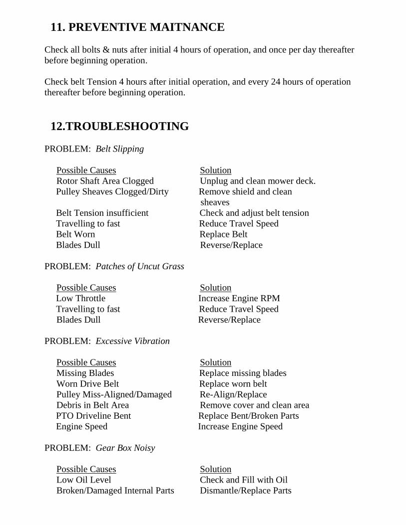
11. PREVENTIVE MAITNANCE
Check all bolts & nuts after initial 4 hours of operation, and once per day thereafter
before beginning operation.
Check belt Tension 4 hours after initial operation, and every 24 hours of operation
thereafter before beginning operation.
12.TROUBLESHOOTING
PROBLEM: Belt Slipping
Possible Causes Solution
Rotor Shaft Area Clogged Unplug and clean mower deck.
Pulley Sheaves Clogged/Dirty Remove shield and clean
sheaves
Belt Tension insufficient Check and adjust belt tension
Travelling to fast Reduce Travel Speed
Belt Worn Replace Belt
Blades Dull Reverse/Replace
PROBLEM: Patches of Uncut Grass
Possible Causes Solution
Low Throttle Increase Engine RPM
Travelling to fast Reduce Travel Speed
Blades Dull Reverse/Replace
PROBLEM: Excessive Vibration
Possible Causes Solution
Missing Blades Replace missing blades
Worn Drive Belt Replace worn belt
Pulley Miss-Aligned/Damaged Re-Align/Replace
Debris in Belt Area Remove cover and clean area
PTO Driveline Bent Replace Bent/Broken Parts
Engine Speed Increase Engine Speed
PROBLEM: Gear Box Noisy
Possible Causes Solution
Low Oil Level Check and Fill with Oil
Broken/Damaged Internal Parts Dismantle/Replace Parts

PROBLEM: Knives Scalping Grass
Possible Causes Solution
Incorrect Cutting Height Adjust Cutting height
Mowing Pattern Change Mowing Pattern
Turning to Quickly Reduce Speed during turns
PROBLEM: Uneven Cut
Possible Causes Solution
Missing/Dull Blades Remove/Replace Blades
Travelling to Fast Reduce Travel Speed
Mower Not Level Adjust 3Pt Linkage
PROBLEM: Tractor Loaded Down by Mower
Possible Causes Solution
Low Engine Speed Increase Engine Throttle
Travelling to Fast Reduce Travel Speed
Blade Area Clogged Clean Blade Area
13. PARTS AND FASTENERS
Your Flail Mower is designed for ease of maintenance. Replacement parts are available
from Betst Power Equipment at 1-877-876-7895 or [email protected] Check the
parts list for specification.
See Parts Diagrams at end of manual
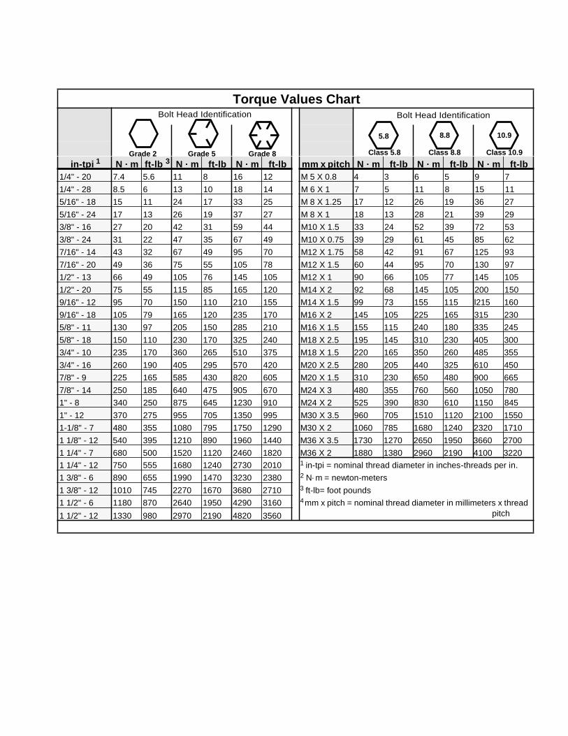
Torque Values Chart Bolt Head Identification
Bolt Head Identification
5.8 8.8 10.9
Grade 2 Grade 5 Grade 8
Class 5.8 Class 8.8 Class 10.9
in-tpi 1 N · m ft-lb 3 N · m ft-lb N · m ft-lb mm x pitch N · m ft-lb N · m ft-lb N · m ft-lb
1/4" - 20 7.4 5.6 11 8 16 12 M 5 X 0.8 4 3 6 5 9 7
1/4" - 28 8.5 6 13 10 18 14 M 6 X 1 7 5 11 8 15 11
5/16" - 18 15 11 24 17 33 25 M 8 X 1.25 17 12 26 19 36 27
5/16" - 24 17 13 26 19 37 27 M 8 X 1 18 13 28 21 39 29
3/8" - 16 27 20 42 31 59 44 M10 X 1.5 33 24 52 39 72 53
3/8" - 24 31 22 47 35 67 49 M10 X 0.75 39 29 61 45 85 62
7/16" - 14 43 32 67 49 95 70 M12 X 1.75 58 42 91 67 125 93
7/16" - 20 49 36 75 55 105 78 M12 X 1.5 60 44 95 70 130 97
1/2" - 13 66 49 105 76 145 105 M12 X 1 90 66 105 77 145 105
1/2" - 20 75 55 115 85 165 120 M14 X 2 92 68 145 105 200 150
9/16" - 12 95 70 150 110 210 155 M14 X 1.5 99 73 155 115 l215 160
9/16" - 18 105 79 165 120 235 170 M16 X 2 145 105 225 165 315 230
5/8" - 11 130 97 205 150 285 210 M16 X 1.5 155 115 240 180 335 245
5/8" - 18 150 110 230 170 325 240 M18 X 2.5 195 145 310 230 405 300
3/4" - 10 235 170 360 265 510 375 M18 X 1.5 220 165 350 260 485 355
3/4" - 16 260 190 405 295 570 420 M20 X 2.5 280 205 440 325 610 450
7/8" - 9 225 165 585 430 820 605 M20 X 1.5 310 230 650 480 900 665
7/8" - 14 250 185 640 475 905 670 M24 X 3 480 355 760 560 1050 780
1" - 8 340 250 875 645 1230 910 M24 X 2 525 390 830 610 1150 845
1" - 12 370 275 955 705 1350 995 M30 X 3.5 960 705 1510 1120 2100 1550
1-1/8" - 7 480 355 1080 795 1750 1290 M30 X 2 1060 785 1680 1240 2320 1710
1 1/8" - 12 540 395 1210 890 1960 1440 M36 X 3.5 1730 1270 2650 1950 3660 2700
1 1/4" - 7 680 500 1520 1120 2460 1820 M36 X 2 1880 1380 2960 2190 4100 3220
1 1/4" - 12 750 555 1680 1240 2730 2010 1 in-tpi = nominal thread diameter in inches-threads per in.
1 3/8" - 6 890 655 1990 1470 3230 2380 2 N· m = newton-meters
1 3/8" - 12 1010 745 2270 1670 3680 2710 3 ft-lb= foot pounds
1 1/2" - 6 1180 870 2640 1950 4290 3160 4 mm x pitch = nominal thread diameter in millimeters x thread
1 1/2" - 12 1330 980 2970 2190 4820 3560 pitch
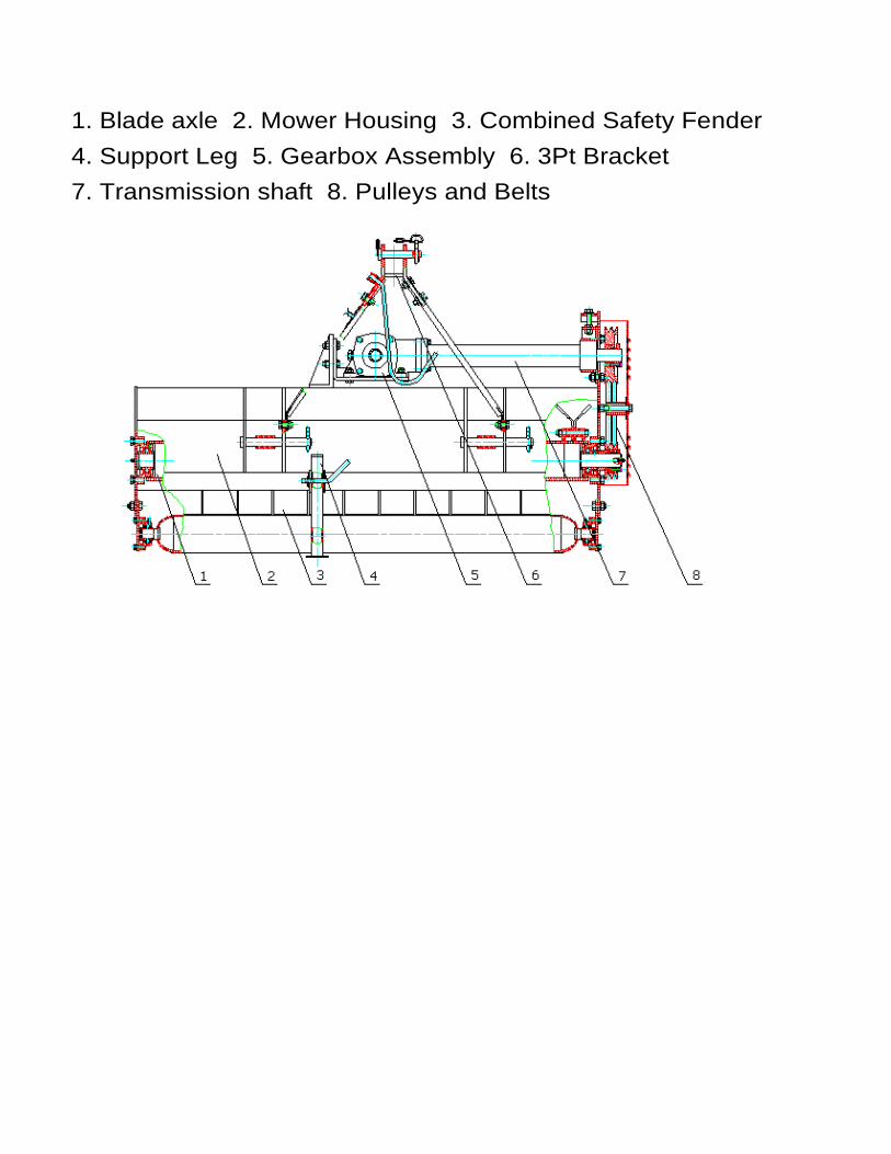
1. Blade axle 2. Mower Housing 3. Combined Safety Fender
4. Support Leg 5. Gearbox Assembly 6. 3Pt Bracket
7. Transmission shaft 8. Pulleys and Belts

Parts Box Includes the following show in picture, you may receive extra parts that are not shown in the picture.
Attach Lower then Upper 3Pt Support Brackets, Storage Stand, and PTO Shield shown in picture
Lubrication Pont on Lower Axle and Pulley Detail Picture
15
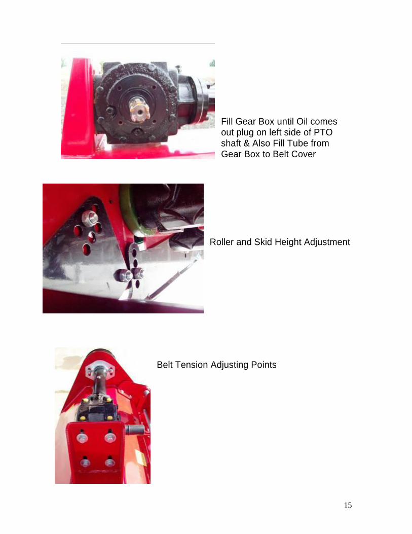
Fill Gear Box until Oil comes out plug on left side of PTO shaft & Also Fill Tube from Gear Box to Belt Cover
Roller and Skid Height Adjustment
Belt Tension Adjusting Points

16
Value Leader VL EFGC Series Flail Mowers Specifications
SPEC VL
EFGC125 VL
EFGC135 VL
EFGC145 VL
EFGC155 VL
EFGC165 VL
EFGC175
Working Width
48" 53" 56" 60" 64" 68"
Overall Width
54" 59" 63" 67" 71"" 75"
Min. HP Req.
22hp 24hp 24hp 25hp 28hp 30hp
Hitch Cat.1 Cat.1 Cat.1 Cat.1 Cat.1 Cat.1
Gear Box Rating
65Hp 65Hp 65Hp 65Hp 65Hp 65Hp
Cutting Offset
1" Offset 5" Offset 8" Offset 12" Offset 17" Offset 22" Offset
Hammer Blades
20 Hammer Blades
24 Hammer Blades
24 Hammer Blades
24 Hammer Blades
28 Hammer Blades
28 Hammer Blades
Optional Grass Blades
40 Blades 48 Blades 48 Blades 48 Blades 56 Blades 56 Blades
Housing Thickness
1/4" 1/4" 1/4" 1/4" 1/4" 1/4"
Side Plate Thickness
1/4" 1/4" 1/4" 1/4" 1/4" 1/4"
Roller Dia. 4" 4" 4" 4" 4" 4"
Rotor Shaft Dia.
4 1/2" 4 1/2" 4 1/2" 4 1/2" 4 1/2" 4 1/2"
Blade Swing 14" 14" 14" 14" 14" 14"
No. of Belts 2 Belts 3 Belts 3 Belts 3 Belts 3 Belts 3 Belts
3pt. Conn. Width
19 3/4" - 27 1/2"
19 3/4" - 27 1/2"
19 3/4" - 27 1/2"
19 3/4" - 27 1/2"
19 3/4" - 27 1/2"
19 3/4" - 27 1/2"
Drive Line Type
Series 4 6-Spline 32"
w/ Shear Bolt
Series 4 6-Spline 32"
w/ Shear Bolt
Series 4 6-Spline 32"
w/ Shear Bolt
Series 5 6-Spline 32"
w/ Shear Bolt
Series 5 6-Spline 32"
w/ Shear Bolt
Series 5 6-Spline 32"
w/ Shear Bolt
Warranty 2 Years 2 Years 2 Years 2 Years 2 Years 2 Years
Weight 610lbs. 642lbs. 697lbs. 730lbs. 763lbs. 789lbs.
Crated Weight
635lbs. 667lbs. 722lbs. 755lbs. 793lbs. 819lbs.
17

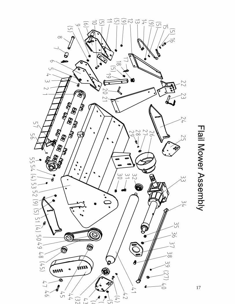
18
Flail Mower Assembly NO. Part NO. Name &Specifications Quantity
1 Blade axle subassembly 1
2 EF100.00.122 Fender 13
3 EF100.00.121 Fender 1
4 GB5783-86 Bolt M12X30 23
5 GB97.1-85 Plain washer 12 40
6 EFGC120.012 Hanging weldment 2
7 EF100.00.106 Spacer 2
8 EF100.00.014 Pin shaft weldment 2
9 GB6184-86 Locking nut M12 44
10 GB5783-86 Bolt M12×40 8
11 EFGC120.101 Splint 4
12 EF100.00.016 Suspension plate (L) 1
13 EF100.00.017 Hook 1
14 EF100.00.105 Clamp for hook 2
15 EF100.00.107 Fixing plate 1
16 GB5783-86 Bolt M12×35 5
17 R pin 1
18 EF100.00.117 Cover 1
19 EF100.00.027 Supporting frame 1
20 EF100.00.111 Bent pin 1
21 EF100.00.020 Suspension plate (R) 1
22 EF100.00.018 Bracket weldment 1
23 EF100.00.019 Pin shaft weldment 1
24 EFGC120.013 Base plate (L) 1
25 EFG120.102 Supporting for roller (L) 1

19
Flail Mower Assembly NO. Part NO. Name &Specifications Quantity
26 EF100.00.112 Guard shade 1
27 GB96-85 Plain washer 10 2
28 GB93-87 Spring washer 10 2
29 GB5783-86 Bolt M10X25 2
30 GB6173-86 Nut M16x1.5 1
31 GB5786-86 Bolt M16X1.5X50 1
32 EF100.00.012 Bearing with flange UC205 2
33 EFGC120.015 Gear box assembly 1
34 EF100.00.024 Mud shield 1
35 GB6184-86 Locking nut M14 2
36 GB97.1-85 Plain washer 14 2
37 EFGC120.102 Tension plate 1
38 GB5783-86 Bolt M14X35 2
39 GB6184-86 Locking nut M8 2
40 GB2673-86 Hex.head bolt M8X25 10
41 EFG120.012 Roller weldment 1
42 GB1152-89 Oil cup M6 2
43 EFG120.101 Supporting for roller (R) 1
44 EFGC120.016 Belt cover 1
45 JB/T7934Z3 Swellable sleeve 2
46 GB5782-86 Bolt M12×80 1
47 GB96-85 Plain washer 12 5
48 GB-T1154-97 Strap A965 2
49 RK120.113 Big belt ptlley 1
50 RK120.110 Small belt ptlley 1

20
Flail Mower Assembly
NO. Part NO. Name &Specifications Quantity
51 EFGC120.014 Base plate (R) 1
52 EFGC120.011 The cover weldment 1
53 GB1152-89 Oil cup M8X1 2
54 GB93-87 Spring washer 12 12
55 GB97.1-85 Plain washer 10 18
56 GB879-86 Elastic cylindrical pin 4x22 2
57 EF100.00.123 Shaft for fender 1
21
22
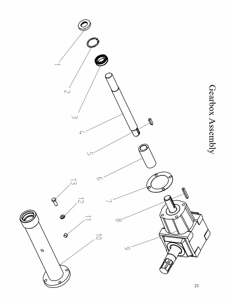
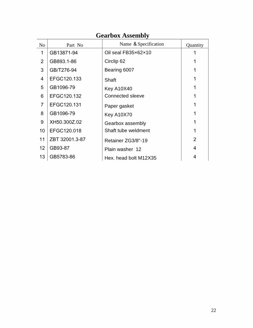
Gearbox Assembly
No Part No Name &Specification Quantity
1 GB13871-94 Oil seal FB35×62×10 1
2 GB893.1-86 Circlip 62 1
3 GB/T276-94 Bearing 6007 1
4 EFGC120.133 Shaft 1
5 GB1096-79 Key A10X40 1
6 EFGC120.132 Connected sleeve 1
7 EFGC120.131 Paper gasket 1
8 GB1096-79 Key A10X70 1
9 XH50.300Z.02 Gearbox assembly 1
10 EFGC120.018 Shaft tube weldment 1
11 ZBT 32001.3-87 Retainer ZG3/8"-19 2
12 GB93-87 Plain washer 12 4
13 GB5783-86 Hex. head bolt M12X35 4
23
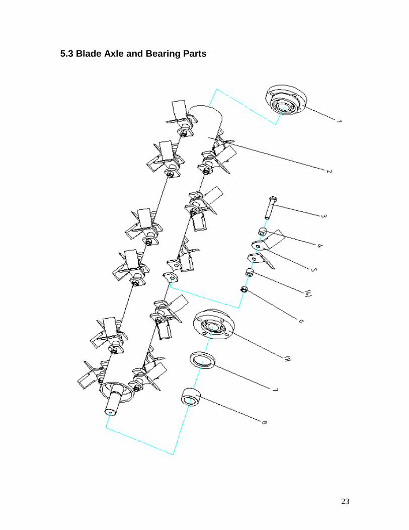
5.3 Blade Axle and Bearing Parts

24
Blade Axle Subassembly
NO. Part NO. Name &Specifications Quantity Remark
1 UC207-Z Bearing with flange 90207 2
2 EFG120.013 Blade axle weldment 1
3 GB5782-86 Bolt M12x80 20 Varies
4 EF100.00.103 Sleeve 40 Varies
5 EF100.00.102 Grass Blade 40 Varies
6 GB6184-86 Locking nut M12 20 Varies
7 GB13871-94 Oil seal FB55X80X8 1
8 RK120.109 Oil-sealing sleeve 1
25
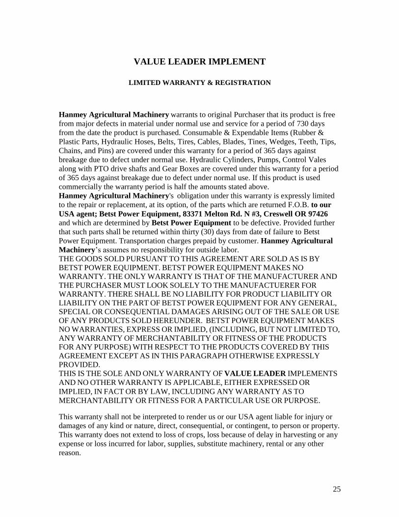
VALUE LEADER IMPLEMENT
LIMITED WARRANTY & REGISTRATION
Hanmey Agricultural Machinery warrants to original Purchaser that its product is free
from major defects in material under normal use and service for a period of 730 days
from the date the product is purchased. Consumable & Expendable Items (Rubber &
Plastic Parts, Hydraulic Hoses, Belts, Tires, Cables, Blades, Tines, Wedges, Teeth, Tips,
Chains, and Pins) are covered under this warranty for a period of 365 days against
breakage due to defect under normal use. Hydraulic Cylinders, Pumps, Control Vales
along with PTO drive shafts and Gear Boxes are covered under this warranty for a period
of 365 days against breakage due to defect under normal use. If this product is used
commercially the warranty period is half the amounts stated above.
Hanmey Agricultural Machinery's obligation under this warranty is expressly limited
to the repair or replacement, at its option, of the parts which are returned F.O.B. to our
USA agent; Betst Power Equipment, 83371 Melton Rd. N #3, Creswell OR 97426
and which are determined by Betst Power Equipment to be defective. Provided further
that such parts shall be returned within thirty (30) days from date of failure to Betst
Power Equipment. Transportation charges prepaid by customer. Hanmey Agricultural
Machinery’s assumes no responsibility for outside labor.
THE GOODS SOLD PURSUANT TO THIS AGREEMENT ARE SOLD AS IS BY
BETST POWER EQUIPMENT. BETST POWER EQUIPMENT MAKES NO
WARRANTY. THE ONLY WARRANTY IS THAT OF THE MANUFACTURER AND
THE PURCHASER MUST LOOK SOLELY TO THE MANUFACTUERER FOR
WARRANTY. THERE SHALL BE NO LIABILITY FOR PRODUCT LIABILITY OR
LIABILITY ON THE PART OF BETST POWER EQUIPMENT FOR ANY GENERAL, SPECIAL OR CONSEQUENTIAL DAMAGES ARISING OUT OF THE SALE OR USE
OF ANY PRODUCTS SOLD HEREUNDER. BETST POWER EQUIPMENT MAKES
NO WARRANTIES, EXPRESS OR IMPLIED, (INCLUDING, BUT NOT LIMITED TO, ANY WARRANTY OF MERCHANTABILITY OR FITNESS OF THE PRODUCTS
FOR ANY PURPOSE) WITH RESPECT TO THE PRODUCTS COVERED BY THIS
AGREEMENT EXCEPT AS IN THIS PARAGRAPH OTHERWISE EXPRESSLY
PROVIDED. THIS IS THE SOLE AND ONLY WARRANTY OF VALUE LEADER IMPLEMENTS
AND NO OTHER WARRANTY IS APPLICABLE, EITHER EXPRESSED OR
IMPLIED, IN FACT OR BY LAW, INCLUDING ANY WARRANTY AS TO
MERCHANTABILITY OR FITNESS FOR A PARTICULAR USE OR PURPOSE.
This warranty shall not be interpreted to render us or our USA agent liable for injury or
damages of any kind or nature, direct, consequential, or contingent, to person or property.
This warranty does not extend to loss of crops, loss because of delay in harvesting or any
expense or loss incurred for labor, supplies, substitute machinery, rental or any other
reason.
26
The sole and only remedy in regard to any defective products shall be the repair or
replacement thereof herein provided, and Hanmey Agricultural Machinery’s nor our
agent BETST POWER EQUIPMENT shall not be liable for any consequential, special,
incidental or punitive damages resulting from or caused by any such defects.
Hanmey Agricultural Machinery’s reserves the right to make improvements in design
or changes in specifications at any time, without incurring any obligations to owners of
units previously sold.
No one is authorized to alter, modify, or enlarge this warranty nor the exclusions,
limitations, and reservation.
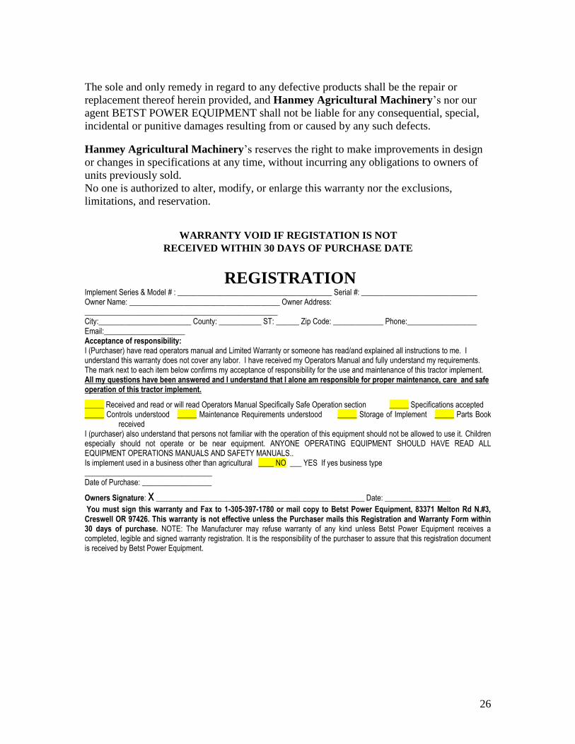
WARRANTY VOID IF REGISTATION IS NOT
RECEIVED WITHIN 30 DAYS OF PURCHASE DATE
REGISTRATION Implement Series & Model # : ________________________________________ Serial #: ______________________________ Owner Name: _______________________________________ Owner Address: __________________________________________________ City:________________________ County: ___________ ST: ______ Zip Code: _____________ Phone:__________________ Email:_____________________ Acceptance of responsibility: I (Purchaser) have read operators manual and Limited Warranty or someone has read/and explained all instructions to me. I understand this warranty does not cover any labor. I have received my Operators Manual and fully understand my requirements. The mark next to each item below confirms my acceptance of responsibility for the use and maintenance of this tractor implement. All my questions have been answered and I understand that I alone am responsible for proper maintenance, care and safe operation of this tractor implement.
_____ Received and read or will read Operators Manual Specifically Safe Operation section _____ Specifications accepted _____ Controls understood _____ Maintenance Requirements understood _____ Storage of Implement _____ Parts Book
received I (purchaser) also understand that persons not familiar with the operation of this equipment should not be allowed to use it. Children especially should not operate or be near equipment. ANYONE OPERATING EQUIPMENT SHOULD HAVE READ ALL EQUIPMENT OPERATIONS MANUALS AND SAFETY MANUALS.. Is implement used in a business other than agricultural ____ NO ___ YES If yes business type _________________________________ Date of Purchase: __________________
Owners Signature: x ______________________________________________________ Date: _________________
You must sign this warranty and Fax to 1-305-397-1780 or mail copy to Betst Power Equipment, 83371 Melton Rd N.#3, Creswell OR 97426. This warranty is not effective unless the Purchaser mails this Registration and Warranty Form within 30 days of purchase. NOTE: The Manufacturer may refuse warranty of any kind unless Betst Power Equipment receives a completed, legible and signed warranty registration. It is the responsibility of the purchaser to assure that this registration document is received by Betst Power Equipment.