efficient, reliable, long-lifetime, diode-pumped nd:yag ... · systems are typically below 5%, at...
TRANSCRIPT
El
D
1
WsAleaDsrso2tpanstusito
AtlU
J
5
fficient, reliable, long-lifetime, diode-pumped Nd:YAGaser for space-based vegetation topographical altimetry
onald B. Coyle, Richard B. Kay, Paul R. Stysley, and Demetrios Poulios
A highly efficient, diode-pumped, Nd:YAG laser is described. The oscillator utilizes an unstable reso-nator design with a Gaussian reflectivity output coupler and a side-pumped zigzag slab gain medium.The laser produces 18-mJ, 10-ns pulses at a repetition rate of 242 Hz in a near-TEM00 mode with anoptical efficiency of up to 14%. An extended performance test was recently concluded in which thetransmitter operated at reduced output for more than 4.8 � 109 shots with no optical damage. Designcriteria, beam quality, and lifetime data are presented. © 2004 Optical Society of America
OCIS codes: 280.3640, 140.3540, 140.3580, 140.5560, 140.6810, 140.3480.
oaFvrthoaidaisSs2tpti
2
AHstarzpDpew
. Introduction
e report on a high efficiency laser, originally de-igned as a prototype transmitter for a Nationaleronautics and Space Administration space-based
idar mission for topographical measurements of thearth, similar to the Vegetation Conopylidar �VCL�nd Geoscience Laser Altimeter System missions.1,2
ata products for such missions require that the la-er wave form be nearly pure Gaussian, both tempo-ally and spatially, with a uniform phase front. Aingle spatial mode insures that no other “hot spots”ther than the central lobe will be present in the5–100-m-diameter ground footprints, and the digi-ized time of flight waveform returns provide the to-ographical structure.3 We first describe the laserrchitecture, including details of the unstable reso-ator and the pump head. Although much of theystem design is standard engineering practice, cer-ain innovative elements are implemented that arenique to this laser. Considerable effort in this de-ign was geared toward maximizing system reliabil-ty and efficiency. In particular, great care has beenaken to ensure that this design could successfullyperate up to two years in space with no self-induced
D. B. Coyle �[email protected]� is with the Nationaleronautics and Space Administration Goddard Space Flight Cen-
er, Code 920, Greenbelt, Maryland 20771. R. B. Kay, P. R. Stys-ey, and D. Poulios are with the Department of Physics, Americanniversity, Washington, D.C. 20016.Received 13 February 2004; revised manuscript received 16
une 2004; accepted 21 June 2004.0003-6935�04�275236-07$15.00�0© 2004 Optical Society of America
236 APPLIED OPTICS � Vol. 43, No. 27 � 20 September 2004
ptical damage. In the VCL project, for example,pproximately 2.3 � 109 pulses per year are required.or damage-free operation in a harsh, hands-off, en-ironment such as space, a major form of damage riskeduction is the creation of a large intracavity modeo reduce the peak fluence. The intracavity mode,owever, must also be small enough to ensure goodptical efficiency, requiring a somewhat delicate bal-ncing act between the two factors. High efficiencys key to future laser-based space missions for re-uced total cost and improved total system reliabilitynd stability. Higher efficiency allows reductions innstrument size, mass, solar array area, drive andupport electronics, and heat removal requirements.ince wallplug efficiencies of diode-pumped Nd:YAGystems are typically below 5%, at best, even a 1% or% improvement is a relatively huge gain. Addi-ional requirements placed on the laser include com-actness, ruggedness, tolerance of moderateemperature variations, and good shot-to-shot point-ng stability.
. Oscillator Architecture
three-dimensional engineering drawing of theigh-Efficiency Laser Transmitter �HELT� is pre-
ented in Fig. 1. The conductively cooled laser fea-ures an optically efficient pump head incorporated inconcave–convex unstable resonator with a graded
eflectivity mirror �GRM� output coupler. The zig-ag slab had near-Brewster end faces, and was sideumped �x axis� with seven four-bar stacks of Spectraiode Labs back-cooled, diode arrays, rated at 60 Wer bar. These diodes were selected to have �49%lectrical-to-optical efficiency upon procurement andere typically operated de-rated by �17% below the

pttptpvaalmlddidssmosrtm
3
Sstmpaeeaevoeos
o
wlieie
woNFronla�t�c1iwaitadtahZtdiTmcoe
tspadatvcnstofu2wb
Fuf
eak output power in order to extend their opera-ional lifetime. The zigzag slab geometry cancels op-ical distortion in one axis to the first order, and sideumping takes advantage of the natural geometry ofhe multistripe diode array, allowing efficient cou-ling of the pump energy into the intraslab modeolume.4,5 The slab has a center length of 95 mmlong its optical z axis and was 2.65 mm thick �x axis�nd 5 mm wide �y axis�. The laser has some simi-arities to the 100-mJ high-brightness design of Ar-
andillo et al.,6 which was also a side-pumped slabaser employing an unstable resonator. The obviousifferences between our design and that of Arman-illo et al. are in output energy and laser head pump-ng geometry. Additionally, there are more subtleifferences, such as our use of an even-bounce slab, atepped heat sink for reduction of thermal lens, ahorter resonator for space conservation, and a largeargin of overhead in pump-diode power. Other di-
de side-pumped slab designs that have gone intopace have not employed an unstable resonator butather used porro or retro prisms as end mirrors forheir expected high alignment stability and largeultimode beam production.7,8
. Slab Details
ince high efficiency was critical to this laser’s pos-ible use as a space-based transmitter, it was decidedo revisit some established solid-state laser develop-ent tools in detail such as zigzag slab design and
ump-volume mode matching. An even-bounce par-llelogram design was used that is less subjected tond-mirror pointing errors than an odd-bounce �trap-zoid� design. An even-bounce slab has entrancend exit window faces that are parallel, so that if thentrance beam deviates upward the output beam de-iates upward at the same angle. A ray entering andd-bounce slab that is not parallel to the z axis willxit the slab at an equal but opposite angle. Thusdd-bounce zigzag slabs exacerbate mechanical sen-itivity.In order to provide maximum gain overlap or “fill”
f the pump beam with the elliptical intraslab mode,
ig. 1. The HELT configuration. It was important to have mod-larity and micrometer motion control on the head and end mirrorsor thorough performance characterization.
20
e set our slab’s tip angle to 26.5°. The x axis of theaser mode, parallel to the zigzag plane, is increasedn the slab by refraction at the end faces. It can beasily shown that the x axis of the intraslab mode ��x�s related to the tip angle and the incident x axisxternal mode ��o� by
�x � �o
cos���
sin���, (1)
here � is the tip angle and � is the refraction anglebtained from Snell’s law. Brewster’s angle ford:YAG at 1.064 �m is B 61.2° and �x��o 1.82.or a tip angle of 26.5°, as used in our design, thisatio increases to 1.95, increasing the x axis diameterf the intraslab beam by �7%. Since the slab face isear Brewster’s angle, the polarized beam loses very
ittle energy owing to reflection. The slab is pumpedlong the x axis with one of the faces high-reflectionHR� coated so that the light is double passed throughhe slab. This yields a calculated absorption of93% when an in-house measurement of absorption
ross section of �abs 3.4 � 10�20 cm2 is used for.1% doped Nd:YAG.9 This effective cross sectionncludes the overlap of the pump-diode spectral widthith the Nd:YAG absorption feature between 805nd 812 nm; this was measured by temperature tun-ng a collimated diode laser to maximum absorptionhrough 1.1% Nd:YAG. Comparison with publishedbsorption data that does not include this overlap isifficult. Spectra typically presented are at rela-ively low resolution.10,11 However, the 1% Nd:YAGbsorption spectra of Zhou et al.12 has sufficientlyigh resolution to be useful. Most importantly,hou et al. also showed the absorption coefficient ofhe GaAlAs laser diode passing through the bulk 1%oped Nd:YAG as the center wavelength of the diodes temperature tuned through the absorption peak.he maximum value from their Fig. 2 is � �4.55m�1. This converts to an effective absorption
ross section of �abs �� 3.3 � 10�20 cm2 by usef 1.38 � 1020 cm�3 for 1% doping and is inxcellent agreement with our value.The intracavity beam 1�e2 diameter was designed
o be �2 mm. The thickness of the slab thereforehould not greatly exceed this, or the zigzag beamath will miss large regions of the pumped volumend not sweep out the stored energy efficiently. Weiscovered inherent aperture effects created by use ofn angle of incidence less than Brewster’s angle forhe x axis and subtle effects on the beam’s y axis fromarying pump beam thickness. Depending upon thehosen slab tip angle, the rays that enter the slabearest to the tip were refracted such that upon theirecond internal total internal reflection they strikehe inside of the slab entrance face rather than thepposing zigzag surface. Such rays were deviatedrom the normal zigzag pattern and did not contrib-te to the cavity mode. For our chosen tip angle of6.5°, the full width of the slab’s acceptance apertureas 2 mm. In combination with our final pumpeam design, the 26.5° tip was very useful in main-
September 2004 � Vol. 43, No. 27 � APPLIED OPTICS 5237

te
4
Sigdm8tmptr
cawimmcds
tqptastwun
tGaGbfatrtb
Ffao F
thr
Fsc
5
aining a single spatial mode while retaining high-nergy extraction efficiency.
. Collimated Pump Beam
ince resonator efficiency depends strongly on thenversion density of the gain medium, it is advanta-eous to confine the pump light in the transverseimension such that it matches the desired cavityode as closely as possible. To accomplish this, the
09-nm light from the diode arrays was collimated inhe fast axis by a single plano-convex cylindrical lensade of undoped YAG. The resulting transverse
ump light distribution from the diode-lens-slab op-ical system was then modeled with a commercialaytracing software package and is shown in Fig. 2.
This pumping scheme can be contrasted with close-oupled side-pumping results in which the diode-rray 809-nm radiation fills the active medium and aeaker thermal lens results. However, such pump-
ng schemes are unsuited for highly efficient 10–20J oscillator designs operating in a near-TEM00ode. Lensed designs can enhance optical effi-
iency by creating an intense stripe of pump energyown the slab length, maximizing the inversion den-ity and cavity mode overlap with the pumped region.Care was taken when positioning the lens relative
o the diode arrays, as the pulse energy and beamuality are sensitive to this adjustment. If theump lens was placed too far from the diode facets,he pump beam would focus inside the slab, creatingstrong thermal lens as well as a number of unde-
irable “hot spots” in the gain medium. Similarly, ifhe lens was too close to the arrays, the pump beamould be too divergent, creating a larger pump vol-me and reducing the optical efficiency of the reso-ator. When the pump lens was optimally situated,
ig. 2. Modeled distribution of pump radiation in slab. Theour-bar diode array and undoped cylindrical lens produces a rel-tively smooth absorption distribution in the Nd:YAG slab, as seenn the right side of the figure.
238 APPLIED OPTICS � Vol. 43, No. 27 � 20 September 2004
he collimated pump beam closely approximated aaussian distribution in the vertical dimension with1�e2 radius of �1.4 mm inside the slab. The
aussian nature of the pump light distribution cane seen in an image of 1064-nm fluorescence emittedrom the slab end in Fig. 3. The ability to preciselydjust both the pump lens-diode array distance andhe slab-diode array to ���0.125 mm was incorpo-ated into the head design. Figures 4 and 5 showhe laser head and a cross section of the final assem-ly.
ig. 3. A CCD image of the 1064-nm fluorescence emanating fromhe end of a rectangular Nd:YAG slab when pumped in the HELTead configuration. The diode energy enters from the left and iseflected off the right slab face for a two-pass pump path.
ig. 4. Pump head configuration �the pump lens mount is nothown�. The Nd:YAG slab is thermally bonded to a molybdenumopper block in order to match thermal expansion coefficients.
5
Cwhtcseutsvmado0lsewiswfpilthsvwfmwn
d
thlplssl
6
Arlnpndcsmmcs
Facis
FsTlitt
. Step Mount
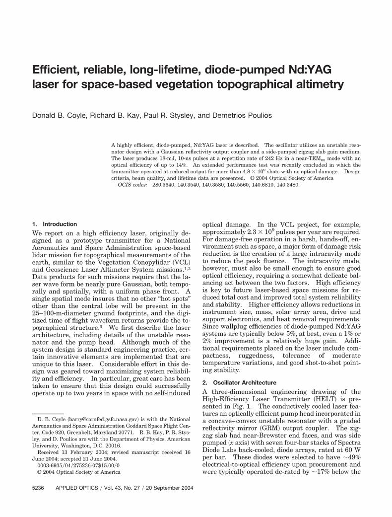
omputer modeling of the laser head assembly,hich included the thermal extraction capability,elped determine the steady-state thermal charac-eristics of the slab. This modeling indicated thatonductive cooling from the HR-coated side of thelab resulted in the smoothest set of thermal gradi-nts compared with cooling the slab from the twoncoated sides. From these calculated isotherms, ahermal lens model was created to predict the lenstrengths that produced results near the measuredalues. Furthermore, thermal modeling of the back-ounted slab shows that the isotherms can be givenless-severe curvature if the thermal conductivity
irectly behind the diode-pump path is higher thann either side. To accomplish this, we machined a.230-mm tall center step along the slab heat sinkength �see expanded view in Fig. 5�. The step has aingle layer of thermally conductive bonding tape onither side of the center and a single layer across thehole bonding width. Figure 6 shows the calculated
sotherms for the flat-surface slab mount and the stepurface, respectively. These results are for pumpingith an average power of 31 W and a 0.36 heating
raction, which is defined as the fraction of pumpower going into heat. The optical power depositionn the slab assumes a Beer’s Law absorption of pumpight marked by the two vertical lines on each side ofhe center. The top center of the slab was found toave a slightly higher temperature at the top of thelab in the step-mounted case ��1 °C�, but the cur-ature of the isotherms was diminished, indicating aeaker thermal lens in the slab. The steady-state
ocal length was reduced from �40 cm with the flatount to �65 cm with the step mount. This lensingas then compensated by the use of an intracavityegative cylindrical lens, shown in Fig. 1.To simulate any future use of such a pump head
esign in a space-based conductively cooled laser sys-
ig. 5. End view of the HELT pump head. This version showsn integrated water path at the base, but the present design islamped to a water-cooled plate to better simulate conductive cool-ng for the complete assembly. Note the stepped slab mountingurface in detail.
20
em, we mounted the unit to a water-cooled plate foreat removal. Here, the diode-array wavelength se-
ection contributed significantly toward final systemerformance. A small reduction in peak thermalensing and temperature sensitivity as well as amall decline in total system efficiency were the re-ults of choosing diode arrays with a significant wave-ength spread ��3.5 nm� around 809 nm.
. Unstable Resonator
n unstable resonator has the capability of creating aelative large beam in a modest geometrical cavityength. When the resonator is coupled with a GRM,ear-TEMoo output can be achieved. The most im-ortant feature of an unstable resonator is its mag-ification M. Magnification directly affects theissipative losses �feedback�, higher-order mode dis-rimination, alignment sensitivity, and the GRM spotize relative to the beam waist in the activeedia.13–15 There are a variety of decisions to beade in arriving at a cavity design and its magnifi-
ation. The unstable resonator was designed in con-ultation with M. Morin of the National Optics
ig. 6. �a� Calculated thermal distribution in the Nd:YAG crossection. The borders between shaded areas represent isotherms.his slab was modeled with a flat heat-sink interface. �b� Calcu-
ated thermal distribution in slab but with a stepped thermalnterface. The introduction of a double layer of thermal conduc-ive tape on the sides of the central region helps reduce the effec-ive thermal lens.
September 2004 � Vol. 43, No. 27 � APPLIED OPTICS 5239

It
r�ocGrRtefTowqo
tmrt
wrrstm�
tnhcEbTh
tescprc
atp
Sdebo
tlibr
7
TastslseCflHtHP
stfi
tnsrlNmGowpcQdwrl
8
A
AHrV2ayrtml
B
Fa
5
nstitute of Canada.16 The Institute also producedhe graded reflectivity output coupler.
The final empty cavity design employed a geomet-ical length of 41 cm with a convex output couplerGRM� radius of �237 cm and a concave HR reflectorf radius �300 cm. This provided a total magnifi-ation �geometrical plus diffraction� of Mt 1.4. Aaussian GRM profile was chosen with an intensity
eflectivity profile of R�r� Ro exp��2�r��m�2�, whereo is the reflectivity in the mirror’s center and �m is
he 1�e2 radius of the profile. To sweep the mostnergy out of the gain medium, we designed the GRMor a beam waist in the Nd:YAG slab of �1.1 mm.he relationship between �i �the beam waist at theutput coupler� and the reflective Gaussian profileaist on the mirror was �i �m�M2 � 1�1�2. Re-uiring �i 1.1 mm gave a Gaussian reflective waistf �m 1.12 mm.Much of unstable resonator design can be reasoned
hrough use of the geometrical approximation of Sieg-an.13 By use of the gi values associated with the
esonator, gi 1 � L�Ri, the geometrical magnifica-ion can be shown to be
Mg � G � �G2 � 1�2 , (2)
here G 2g1 � g2 � 1 and is equal to 1.265 for ouresonator. As mentioned above, the complete theo-etical calculation gave a magnification of 1.4, whichhowed the effects of diffraction and the limitation ofhe geometrical approximation in our case. Theode discrimination between the fundamental mode
o and higher-order modes �n was
�n � �o��M�2n , (3)
hus high magnification was desirable. Unfortu-ately, very high values of magnification give rise toigher losses that cannot be overcome in most appli-ations. Substituting 1.4 for the magnification inq. �3� indicates we had a factor-of-2 discriminationetween the fundamental and the next-highest mode.he GRM further aided in discrimination againstigher-order modes.Feedback for the first-order mode has been shown
o be �R� Ro�M2. Our requirements were for anffective output-coupler feedback of �0.32. This re-ult was based on a plane-wave analysis that in-luded the gain and dissipative losses expected in thehysical cavity design.17,18 To achieve an effectiveeflectivity of �R� � 0.32, we required a Gaussianenter reflectivity of Ro � 63% for M 1.4.
Another important consideration is the cavitylignment stability. Krupke and Sooy19 showedhat the angular alignment sensitivity S can be ex-ressed as
S � �1 � g2���1 � g1� . (4)
maller values of this parameter are desirable. Byefinition, unstable resonators have values of g1g2ither greater than 1 or less than 0. For positiveranch resonators, which apply in our case, the valuef g g is not far from unity. It is another design
1 2240 APPLIED OPTICS � Vol. 43, No. 27 � 20 September 2004
rade-off to arrive at a resonator that has a relativelyow S and a reasonable magnification. For our cav-ty, the design sensitivity value of S � 10. This cane compared to a value of S � 3 for a very stableesonator with g1g2 � 0.5.
. Experimental Procedure to Optimize the Laser
he thermal lens created in the slab was a function ofverage pump power and lasing efficiency. The la-er was optimized at a single pump power for whichhe intracavity negative cylindrical lens best compen-ated the positive thermal lens in the slab. The slabens changed strength as the laser achieved steady-tate performance, owing to the effect of stimulatedmission cooling; this effect was readily seen in theCD array beam analysis. To understand the ef-
ects of various cylindrical lenses on the cavity oscil-ator performance, we measured the spot sizes on theR and the GRM using 2f imaging systems in addi-
ion to the far-field pattern. The beam waists on theR and GRM were compared to results produced by
ARAXIA modeling of the resonator.20 This compari-on allowed us to determine the effective strength ofhe thermal lens under operation, and helped us tone tune the final operation of the laser.We initially fired the laser in quasi-cw mode. If
he thermally compensating cylindrical lens is tooegative, output power was low and the imaged beampots on the mirrors were large relative to the designadius �1 mm. The cylindrical lens was then madeess negative until the design spot size was obtained.ext, the laser was Q switched, and small adjust-ents made until the far-field pattern was nearlyaussian in both axes. It was an interesting featuref the unstable resonator that the Q-switched poweras significantly greater than that found in the long-ulse mode. This, of course, is not the case in stableavity resonators. Typically, our unstable-cavity-switched pulse energy was greater than that pro-uced in long-pulse mode by about 25%–30%. Thisas due to the high losses attendant to the unstable
esonator, which affect the inversion negatively whenasing in quasi-cw.
. Lifetime Study and Summary of Results
. Lifetime Study
fter completing its initial configuration tests,ELT was put through a simulation of the laser
equirements over the two-year VCL mission.CL output specifications required the laser to fire.4 � 109 shots at a pulse energy of 10–15 mJ overone-year period.1 In the simulation of the second
ear, the pump pulse width would be increased toegain lost pump energy due to diode-array degrada-ion. Additionally, the beam quality was required toaintain �2.7 mm mrad, or �2 times the diffraction
imit.
. Setup
igure 7 shows the configuration of the lab and datacquisition system. The test facility was employed
fmmtctapssew3smlsflbt
C
Fldpf
twautbwmcttacotiWithwto
b
Fw
Fttsct
Fm
or measuring the laser’s short- and long-term perfor-ance. The life test was semiautomated, and perfor-ance parameters such as pulse energy,
emperatures, and far-field �FF� divergence were re-orded. We paid particular attention to beam sizes onhe HR mirror in order to keep an accurate real-timeccount of the intracavity fluence. The HR mirror’sroximity to the slab provided a more accurate mea-ure of the fluence near the slab, the most damage-ensitive optic in the cavity. From head assemblyxperiments discussed earlier, we determined that itas important to avoid going over a intracavity fluenceJ�cm2 to avoid optical damage. Long-term pointing
tability was not an important factor for this experi-ent, since most of the components were held in un-
ockable commercial gimbal mounts and translationtages for alignment sensitivity experiments. If aight unit is to be built, further long-term testing wille required for pointing and other parameters relevanto the particular mission selected.
. Data and Measurements
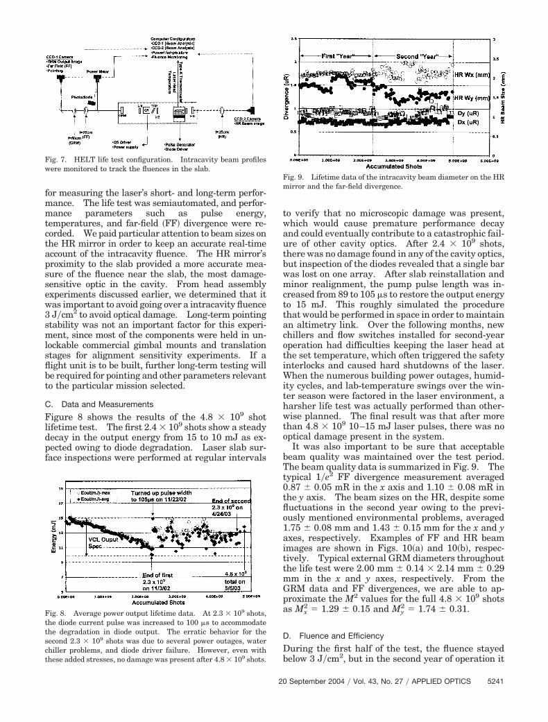
igure 8 shows the results of the 4.8 � 109 shotifetime test. The first 2.4 � 109 shots show a steadyecay in the output energy from 15 to 10 mJ as ex-ected owing to diode degradation. Laser slab sur-ace inspections were performed at regular intervals
Tt0tflo1aittmGpa
D
Db
20
o verify that no microscopic damage was present,hich would cause premature performance decaynd could eventually contribute to a catastrophic fail-re of other cavity optics. After 2.4 � 109 shots,here was no damage found in any of the cavity optics,ut inspection of the diodes revealed that a single baras lost on one array. After slab reinstallation andinor realignment, the pump pulse length was in-
reased from 89 to 105 �s to restore the output energyo 15 mJ. This roughly simulated the procedurehat would be performed in space in order to maintainn altimetry link. Over the following months, newhillers and flow switches installed for second-yearperation had difficulties keeping the laser head athe set temperature, which often triggered the safetynterlocks and caused hard shutdowns of the laser.
hen the numerous building power outages, humid-ty cycles, and lab-temperature swings over the win-er season were factored in the laser environment, aarsher life test was actually performed than other-ise planned. The final result was that after more
han 4.8 � 109 10–15 mJ laser pulses, there was noptical damage present in the system.It was also important to be sure that acceptable
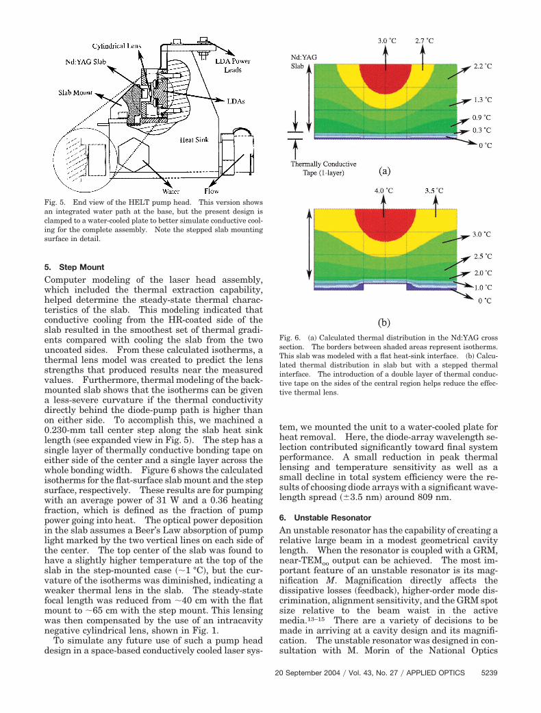
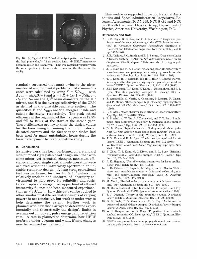
eam quality was maintained over the test period.he beam quality data is summarized in Fig. 9. Theypical 1�e2 FF divergence measurement averaged.87 � 0.05 mR in the x axis and 1.10 � 0.08 mR inhe y axis. The beam sizes on the HR, despite someuctuations in the second year owing to the previ-usly mentioned environmental problems, averaged.75 � 0.08 mm and 1.43 � 0.15 mm for the x and yxes, respectively. Examples of FF and HR beammages are shown in Figs. 10�a� and 10�b�, respec-ively. Typical external GRM diameters throughouthe life test were 2.00 mm � 0.14 � 2.14 mm � 0.29m in the x and y axes, respectively. From theRM data and FF divergences, we are able to ap-roximate the M2 values for the full 4.8 � 109 shotss Mx
2 1.29 � 0.15 and My2 1.74 � 0.31.
. Fluence and Efficiency
uring the first half of the test, the fluence stayedelow 3 J�cm2, but in the second year of operation it
ig. 7. HELT life test configuration. Intracavity beam profilesere monitored to track the fluences in the slab.
ig. 8. Average power output lifetime data. At 2.3 � 109 shots,he diode current pulse was increased to 100 �s to accommodatehe degradation in diode output. The erratic behavior for theecond 2.3 � 109 shots was due to several power outages, waterhiller problems, and diode driver failure. However, even withhese added stresses, no damage was present after 4.8 � 109 shots.
ig. 9. Lifetime data of the intracavity beam diameter on the HRirror and the far-field divergence.
September 2004 � Vol. 43, No. 27 � APPLIED OPTICS 5241
rmeADmaqoeaTfdbl
9
Esscastrvtitophpiarpm
ns5P
R
1
1
1
1
1
1
1
1
1
1
2
Ftbtc
5
egularly surpassed that mark owing to the afore-entioned environmental problems. Maximum flu-
nces were calculated by using F E�AAVG, withAVG ��DXDY��8 and E ��R � 1���1 � R��EOUT.X and DY are the 1�e2 beam diameters on the HRirror, and R is the average reflectivity of the GRM
s defined in the unstable resonator section. Theuantities E and EOUT are the energies inside andutside the cavity, respectively. The peak opticalfficiency at the beginning of the first year was 12.5%nd fell to 10.4% at the start of the second year.hese efficiencies are lower than the design values
or the laser owing to running the pump diodes ate-rated current and the fact that the diodes hadeen used for many untabulated hours during theaser development before the lifetime study.
. Conclusions
xtensive work has been performed on a standardide-pumped zigzag slab head design such that withome minor, yet essential, changes, maximum effi-iency and good single spatial mode operation werechieved without an intracavity aperture in an un-table resonator design. A long-term operationalest was performed for over 4.8 � 109 pulses in aelatively unclean and uncontrolled laboratory en-ironment to help prove its reliability and resis-ance to optical damage. An upper limit of allowedntracavity fluence has been measured experimen-ally as � 3 J�cm2. How this data can be applied tother similar unstable resonator designs of varyingowers is not conclusive, but work is under way toelp determine the extent. Further work islanned with new diode arrays to determine exper-mentally and theoretically the design’s limits inverage output power, pulse energy, and repetitionate. A test is planned to determine how HELTerforms under vacuum and what, if any, changes
ig. 10. �a� Typical HELT far-field output pattern as formed athe focal plane of a f 75 cm positive lens. �b� HELT intracavityeam image on the HR mirror. This was captured regularly withhe other pertinent lifetime data to monitor the fluence in theavity.
ay be required in the design.
242 APPLIED OPTICS � Vol. 43, No. 27 � 20 September 2004
This work was supported in part by National Aero-autics and Space Administration Cooperative Re-earch Agreements NCC 5-269, NCC 5-482 and NCC-630 with the Laser Physics Group, Department ofhysics, American University, Washington, D.C.
eferences and Note1. D. B. Coyle, R. B. Kay, and S. J. Lindauer, “Design and per-
formance of the vegetation canopy lidar �VCL� laser transmit-ter,” in Aerospace Conference Proceedings �Institute ofElectrical and Electronics Engineers, New York, 2002�, Vol. 3,pp. 1457–1464.
2. J. B. Abshire, J. C. Smith, and B. E. Schutz, “Geoscience LaserAltimeter System �GLAS�,” in 17th International Laser RadarConference �Sendi, Japan, 1994�; see also http:��glas.gsfc.nasa.gov�.
3. J. B. Blair and M. A. Hofton, “Modeling laser altimeter returnwaveforms over complex vegetation using high-resolution ele-vation data,” Geophys. Res. Lett. 26, 2509–2512 �1999�.
4. T. J. Kane, R. C. Eckardt, and R. L. Byer, “Reduced thermalfocusing and birefringence in zig-zag slab geometry crystallinelasers,” IEEE J. Quantum Electron. 19, 1351–1354 �1983�.
5. J. M. Eggleston, T. J. Kane, K. Kuhn, J. Unternahrer, and R. L.Byer, “The slab geometry laser-part I: theory,” IEEE J.Quantum Electron. 20, 289–301 �1984�.
6. E. Armandillo, C. Norrie, A. Cosentino, P. Laporta, P. Wazen,and P. Maine, “Diode-pumped high efficiency high-brightnessQ-switched Nd:YAG slab laser,” Opt. Lett. 22, 1168–1170�1997�.
7. R. S. Afzal, “Mars observer laser altimeter-laser transmitter,”App. Opt. 33, 3184–3188 �1994�.
8. R. S. Afzal, A. W. Yu, J. J. Zayhowski, and T. Y. Fan, “Single-mode high-peak-power passively Q-switched diode-pumpedNd:YAG laser,” Opt. Lett. 22, 1314–1316 �1997�.
9. D. B. Coyle, “Injection seeded, diode-pumped, short pulseNd:YAG ring laser for space based laser ranging,” Ph.d. Dis-sertation �American University, Washington, D.C., 1992�.
0. T. Y. Fan and R. L. Byer, “Diode laser-pumped solid statelasers,” IEEE J. Quantum Electron. 24, 895–912 �1988�.
1. W. Koechner, Solid-State Laser Engineering �Springer, NewYork, 1999�.
2. B. Zhou, T. J. Kane, G. J. Dixon, and R. L. Byer, “Efficient,frequency-stable laser-diode-pumped Nd:YAG laser,” Opt.Lett. 10, 62–64 �1985�.
3. A. E. Siegman, “Unstable optical resonators for laser applica-tions,” Proc. IEEE 53, 277–287 �1965�.
4. S. De Silvestri, P. Laporta, M. Magni, and O. Svelto, “Solid-state laser unstable resonators with tapered reflectivity mir-rors: the super-Gaussian approach,” IEEE J. QuantumElectron. 24, 1172–1177 �1988�.
5. M. Morin, “Graded reflectivity mirror unstable laser resona-tors,” Opt. Quantum Electron. 29, 819–866 �1997�.
6. M. Morin, National Optics Institute, 369 Franquet, Saint-Foy,Quebec, Canada G1P 4N8, �personal communication, 1998�.
7. J. J. Degnan, “Theory of the optimally coupled Q-switchedlaser,” IEEE J. Quantum Electron. 25, 214–220 �1989�.
8. D. B. Coyle, D. V. Guerra, and R. B. Kay, “An interactivenumerical model of diode-pumped, Q-switched�cavity dumpedlasers,” J. Appl. Phys. 28, 452–462 �1995�.
9. W. F. Krupke and W. R. Sooy, “Properties of an unstableconfocal resonator CO2 laser system,” IEEE J. Quantum Elec-tron. 5, 575–86 �1969�.
0. PARAXIA is a general laser beam propagation and laser resona-
tor analysis program. See http:��www.sciopt.com.