effects of the advance ratio on flow structures around ... · effects of the advance ratio on flow...
TRANSCRIPT

Effects of the advance ratio on flow structures around marine propeller
HYUN SIK YOON
Global core research center for ships and offshore plants
Pusan National University
Jang Jeon 2-Dong, Geum Jeong Gu, Busan 609-735
KOREA
Abstract: - This study numerically carried out the propeller open water test (POW) by solving Navier-Stokes
equations governing the three-dimensional unsteady incompressible viscous flow with the turbulence closure
model of the k-ω SST model. Numerical simulations were performed at wide range of advance ratios. A great
difference of velocity magnitude between the inner region and the outer region of the slipstream tube forms the
thick and large velocity gradient which originates from the propeller tip and develops along the downstream.
Eventually, the strong shear layer appears and plays the role of the slipstream boundary. As the advance ratio
increases, the vortical structures originated from the propeller tips quickly decay. The contraction of the
vortices trace is considerable with decreasing the advance ratio.
Key-Words: - propeller, wake, tip vortex, slipstream, advance ratio, KP505
1 Introduction As marine vehicles become larger and faster, the
loading on their propeller blades increases. This
increased propeller loading may lead to problems
such as noise, hull vibration, and cavitation at high
speed. The geometry of a propeller should therefore
be designed to minimize them. In general, modern
propeller blades have a complicated geometry,
making the wake behind the propellers complicated
too. Therefore, any serious attempt to optimize the
geometrical shape of modern propellers will require
a reliable wake analysis based on detailed
experimental measurements.
The flow field analysis around a propeller is
complicated by many factors as unsteadiness, three-
dimensionality, and high turbulence levels. These
properties have been pointed out in many previous
experiments such as Laser Doppler Velocimetry
(LDV) measurements and PIV measurements. Stella
et al. (1998) measured the axial velocity component
of a propeller wake, and Chesnaks and Jessup,
(1998) investigated the tip vortex flow using LDV.
Cotroni et al. (2000) have used PIV and particle
tracking velocimetry (PTV), respectively, to
investigate the near-wake of an isolated marine
propeller in longitudinal planes. Calcagno et al.
(2002) investigated the complicated 3-D flow
behind a marine propeller in the transverse and
longitudinal planes using a stereoscopic PIV (SPIV) technique. Lee et al. (2004) have compared
the flow structures of the same marine propeller for
the cases of open free surface and closed surface
flows at a rather low Reynolds number.
Recently, due to the improvements of computer
performances, Reynolds Averaged Navier Stokes
(RANS) solvers are becoming the practical tool.
Abdel-Maksoud et al. (1998) investigated viscous
flow simulations for conventional and high skew
marine propellers. Chen and Stern (1999) evaluated
computational fluid dynamics of four-quadrant
marine-proposer flow. Watanabe et al. (2003)
examined simulation of steady and unsteady
cavitation on a marine propeller using a RANS code.
Rhee and Joshi (2005) estimated computational
validation for flow around marine propeller using
unstructured mesh based Navier-Stokes solver.
Kawamura et al. (2006) investigated Simulation of
unsteady cavitating flow around marine propeller
using a RANS CFD code. Mitja Morgut and Enrico
Nobile (2009) evaluated Comparison of Hexa-
Structured and Hybrid-Unstructured Meshing
Approaches for Numerical Prediction of the Flow
around Marine Propellers.
As authors’ literature survey, there is a few research
that provided correlations between the vortical
structures and wake in obedience to advance ratio.
Therefore, the present study focuses on the propeller
induced flow structures such as of the propeller
slipstream and the tip vortex according to the
advance ratio.
WSEAS TRANSACTIONS on FLUID MECHANICS Hyun Sik Yoon
E-ISSN: 2224-347X 88 Volume 10, 2015

Table 1 Principal particulars of KP505
KP505 Principal
Scale Ratio 31.6
Diameter, D(m) 0.250
Pitch/Diameter mean 0.950
Ae/A0 0.800
Hub ratio 0.180
No. of Blades 5
Section NACA66
2 Numerical details
2.1 Governing equations Ship hydrodynamic problems are generally
solved with the numerical code in the framework of
the Reynolds-Averaged Navier-Stokes (RANS)
equations. The continuity equation is
0vt
(1)
and the momentum equations are
( )v vv p g Fat
(2)
where p is the static pressure, is the stress tensor,
and g and F are the gravitational body force and
external body forces (e.g., that arise from interaction
with the dispersed phase), respectively, F also
contains other model-dependent source terms such
as porous-media and user-defined sources.
In the Reynolds averaging, the dependent variables
in the instantaneous (exact) Navier-Stokes equations
are decomposed into the mean (ensemble-averaged
or time-averaged) and fluctuating components. So
the Eqs.(1) and (2) can be written in Cartesian
tensor form as
0uit x
i
(3)
2
3
u u ui i jt x j
up u uji l u uij i jx x xx x xi j jj i l
(4)
where ij is the Kronecker delta and i ju u are the
unknown Reynolds stresses
2
3
uu uji lu u ki j t t ijx x x
j i l
(5)
The equations are made closed with the turbulence
model, and here the k SST model is employed:
kk ku G Y S
i k k k kt x x xi j j
(6)
uit x
i
G Y D Sx x
j j
(7)
In these equations, k
G represents the generation of
turbulence kinetic energy due to mean velocity
gradients, G
the generation of , k
and
the
effective diffusivities of k and , respectively, k
Y
and Y
the dissipations of k and due to
turbulence, D
the cross-diffusion term, and k
S and
S
the user-defined source terms.
2.2 Numerical methods The RANS formulations are used and equations are
solved in a sliding interface method used for
unsteady-flow mode. The pressure-velocity
coupling and the overall solution procedure are
based on the SIMPLEC algorithm. The second-
order scheme is used for pressure, convection terms
and second-order central difference scheme for
diffusion terms.
2.3 Computational schemes In the case of unsteady simulation, the whole
domain should be computed with the sliding mesh
technique. The computational domain is defined
with a cylinder of 8.6D diameter surrounding the
propeller and hub. The inlet and outlet boundaries
are located at 2.4D upstream and 5.3D downstream
the center of the propeller respectively. The domain
is split into global stationary part and moving part
which is specified by a smaller cylinder enclosing
the blades and hub entirely. Trimmer mesh is
employed for the global stationary block.
WSEAS TRANSACTIONS on FLUID MECHANICS Hyun Sik Yoon
E-ISSN: 2224-347X 89 Volume 10, 2015

Fig. 1 Geometry of KP505
Fig. 2 Coordinate system of KP505
Fig. 3 Schematic of the computational domain and
boundary conditions.
(a) (b)
Fig. 4 Generated grid of (a) overview and (b)
propeller around
2.4 Validation The computed and measured open water data are
compared in Fig.6, in which three groups of
computed TK , QK and 0 are included. The results
for propeller performance is similar with the
experimental results (Fujisawa et al. 2000)
especially at smaller J values, such as at J = 0.2~0.5
with the differences of smaller than 7% for QK and
at all J values the differences are smaller than 5%
for TK .
As J grows larger, the difference for performance
becomes larger. The reason of the big differences
may partly be due to the very small absolute value
of performance and the doubted experimental results
at large values of J may be also considered.
Fig. 5 Validation of open water test and difference
3 Results and discussion
The typical instantaneous velocity vectors and the
axial velocity contours in the plane normal to the
propeller plane at phase angle Ф=0 are plottd in Fig.
6 where representatively two advance ratios of J=0.2
and 0.7 are considered. The propeller axis is aligned
with y/D = 0, and the propeller plane locates at x/D
= 0. In genreal, the flow behind the propeller is
composed of the slipstream tube and the tip vortices,
which is more clearly identified with decreasing the
advance ratio. At J=0.2 which is the smallest
advance ratio or the heaviest load condition among
the the advance ratios considered in this study, the
freestream and the propeller induced flow superpose,
forming the slipstream with the relatively strong
flow with large velocity vectors forms within the
propeller tip out of which the frestream velocity is
predominent to the flow, as shown in Fig. 6(a).
WSEAS TRANSACTIONS on FLUID MECHANICS Hyun Sik Yoon
E-ISSN: 2224-347X 90 Volume 10, 2015

This strafication of the flow is clarified by the
contours of the axial velocity in Fig. 6(b). The
velocity magnitude in the slipstream tube is much
larger than that ouside of the slipstream. This big
difference of velocity magnitude between the inside
and the out side of the slipstream tube forms the
thick and large velocity gradient which originates
from the propeller tip and develops along the
downstream. Eventually, the strong shear layer
appears and play the role of the slipstream boundary.
(a)
(b)
Fig. 6 Typical instantaneous velocity vector fields
and axil velocity contour in the longitudinal plane at
Ф=0˚ (a) J=0.2, (b) J=0.7.
As the advance ratio increases, the propeller load
becomes light. Therefore, the difference of velocity
magnitude between the slipstream and the outside
becomes minor, resulting in almost disappearance of
the shear layer which clearly appeared at lower
advance ratio of J=0.2 in Figs. 6(a) and 6(b). These
variations of the wake according to the increases of
the advance ratio are clarified by the velocity
vectors and the axial velocity contours as shown in
Figs. 5(c) and 5(d), respectively.
The other component of the near wake of the
propeller is the tip vortices which are shed
successively from the tip of each blade with a
regular interval. Paik et al. (2007) used the Galilean
decomposition method to understand the coherent
vortex structure of the wake behind a rotating
propeller. Thus, the present study also adopts the
Galilean decomposition method to identify the
regular appearance of the tip vortices along the
downstream behind of the propeller.
Fig. 7 shows the appropriately decomposed
instantaneous velocity field for two advance ratios
of J=0.2 and 0.7. The several different convection
velocities as the translational velocity of vortices are
considered to obtain the proper value of the
convection velocity (Uc) which is subtracted from
the axial component of the instantaneous velocity as
already shown in Fig. 6 to detect the rotational flow
corresponding to the tip vortices. Eventually, in the
present study, Uc =1.2U0 is adapted to the Galilean
decomposition.
(a)
WSEAS TRANSACTIONS on FLUID MECHANICS Hyun Sik Yoon
E-ISSN: 2224-347X 91 Volume 10, 2015
(b)
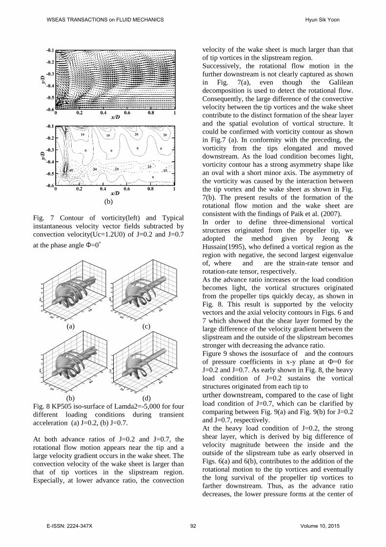
Fig. 7 Contour of vorticity(left) and Typical
instantaneous velocity vector fields subtracted by
convection velocity(Uc=1.2U0) of J=0.2 and J=0.7
at the phase angle Ф=0˚
(a) (c)
(b) (d)
Fig. 8 KP505 iso-surface of Lamda2=-5,000 for four
different loading conditions during transient
acceleration (a) J=0.2, (b) J=0.7.
At both advance ratios of J=0.2 and J=0.7, the
rotational flow motion appears near the tip and a
large velocity gradient occurs in the wake sheet. The
convection velocity of the wake sheet is larger than
that of tip vortices in the slipstream region.
Especially, at lower advance ratio, the convection
velocity of the wake sheet is much larger than that
of tip vortices in the slipstream region.
Successively, the rotational flow motion in the
further downstream is not clearly captured as shown
in Fig. 7(a), even though the Galilean
decomposition is used to detect the rotational flow.
Consequently, the large difference of the convective
velocity between the tip vortices and the wake sheet
contribute to the distinct formation of the shear layer
and the spatial evolution of vortical structure. It
could be confirmed with vorticity contour as shown
in Fig.7 (a). In conformity with the preceding, the
vorticity from the tips elongated and moved
downstream. As the load condition becomes light,
vorticity contour has a strong asymmetry shape like
an oval with a short minor axis. The asymmetry of
the vorticity was caused by the interaction between
the tip vortex and the wake sheet as shown in Fig.
7(b). The present results of the formation of the
rotational flow motion and the wake sheet are
consistent with the findings of Paik et al. (2007).
In order to define three-dimensional vortical
structures originated from the propeller tip, we
adopted the method given by Jeong &
Hussain(1995), who defined a vortical region as the
region with negative, the second largest eigenvalue
of, where and are the strain-rate tensor and
rotation-rate tensor, respectively.
As the advance ratio increases or the load condition
becomes light, the vortical structures originated
from the propeller tips quickly decay, as shown in
Fig. 8. This result is supported by the velocity
vectors and the axial velocity contours in Figs. 6 and
7 which showed that the shear layer formed by the
large difference of the velocity gradient between the
slipstream and the outside of the slipstream becomes
stronger with decreasing the advance ratio.
Figure 9 shows the isosurface of and the contours
of pressure coefficients in x-y plane at Ф=0 for
J=0.2 and J=0.7. As early shown in Fig. 8, the heavy
load condition of J=0.2 sustains the vortical
structures originated from each tip to
urther downstream, compared to the case of light
load condition of J=0.7, which can be clarified by
comparing between Fig. 9(a) and Fig. 9(b) for J=0.2
and J=0.7, respectively.
At the heavy load condition of J=0.2, the strong
shear layer, which is derived by big difference of
velocity magnitude between the inside and the
outside of the slipstream tube as early observed in
Figs. 6(a) and 6(b), contributes to the addition of the
rotational motion to the tip vortices and eventually
the long survival of the propeller tip vortices to
farther downstream. Thus, as the advance ratio
decreases, the lower pressure forms at the center of
WSEAS TRANSACTIONS on FLUID MECHANICS Hyun Sik Yoon
E-ISSN: 2224-347X 92 Volume 10, 2015

each tip vortices, which can be clarified by
comparing between Fig. 9(a) and Fig. 9(b) for J=0.2
and J=0.7, respectively. Additional, in the slipstream
region, the pressure becomes much lower with
decreasing the advance ratio.
(a)
(b)
Fig. 9 Contour of pressure coeffcient in the
longitudinal plane at Ф =0 ˚ .
(a) J=0.2, (b) J=0.7
The traces of the tip vortices shed from each
propeller tip are plotted in Fig. 10 where the
location of the tip vortex is identified by the center
of the tip vortex (maximum vorticity, the place of
the lowest pressure) as observed in Fig. 8. As the
advance ratio decreases, the contraction of the trace
is considerable. Especially, the slope of the
contraction is rapid near wake region owing to the
stronger interaction between the tip vortices with
higher rotational energy, regardless of the advance
ratio. Then the trace becomes saturated earlier with
increasing the advance ratio.
Fig. 10 Location of tip vortices on the X-Y plane
and contraction rates(right) for different advance
ratio of J=0.2~0.8
4 Conclusions
This study numerically carried out the propeller
open water test (POW) by solving Navier-Stokes
equations governing the three-dimensional unsteady
incompressible viscous flow with the turbulence
closure model of the Κ-ω SST model. Numerical
simulations were performed at wide range of
advance ratios. A great difference of velocity
magnitude between the inner region and the outer
region of the slipstream tube forms the thick and
large velocity gradient which originates from the
propeller tip and develops along the downstream.
Eventually, the strong shear layer appears and plays
the role of the slipstream boundary. As the advance
ratio increases, the vortical structures originated
from the propeller tips quickly decay. The
contraction of the vortices trace is considerable with
decreasing the advance ratio.
WSEAS TRANSACTIONS on FLUID MECHANICS Hyun Sik Yoon
E-ISSN: 2224-347X 93 Volume 10, 2015

Acknowledgement
This work was supported by National Research
Foundation of Korea (NRF) grant founded by the
Korea government (MSIP) through (No. 2010-
0025618) and GCRC-SOP (No. 2011-0030013)
and.
References:
[1] J. Jeong and F. Hussain, On the identification
of a vortex, Journal of Fluid Mehanics, vol. 285,
1995, pp. 69-94.
[2] M. Abdel-Maksoud, F. Menter, and H. Wuttke,
Viscous flow simulations for conventional and
highskew marine propellers. Ship Technology
Research, Vol. 45, 1998, pp.64 – 71.
[3] A. Stella, G. Guj, F. Di Felice, M. Elefante,
Propeller wake evolution analysis by LDV.
Proc of 22nd Symposium on Naval
Hydrodynamics, Washington D.C., 1998, pp.
171-188.
[4] C. Chesnaks and S. Jessup, Experimental
characterisation of propeller tip flow. Proc of
22nd Symposium on Naval Hydrodynamics,
Washington D.C., 1998, pp.156–169.
[5] B. Chen, and F. Stern, Computational fluid
dynamics of four-quadrant marine-propulsor
flow. Journal of Ship Research, Vol. 43(4),
1999, pp.218 – 228.
[6] A. Cotroni, F. Di Felice, G. P. Romano and M.
Elefante, Investigation of the near wake of a
propeller using particle image velocimetry. Exp
Fluids, Vol. 29, 2000, pp.227–236.
[7] G. Calcagno, F, Di Felice, M. Felli, and F.
Pereira, Propeller wake analysis behind a ship
by stereo PIV. Proc of 24th Symposium on
Naval Hydrodynamics, Fukuoka, Vol.3, 2002,
pp.112–127.
[8] T. Watanabe, T. Kawamura, Y. Takekoshi, M.
Maeda and S. H. Rhee, Simulation of steady
and unsteady cavitation on a marine propeller
using a rans cfd code. In Fifth International
Symposium on Cavitation, CAV2003, Osaka,
Japan, 2003.
[9] S. J. Lee, B. G. Paik, J. H. Yoon and C. M. Lee,
Three-component velocity field measurements
of propeller wake using a stereoscopic PIV
technique, Experiments in Fluids, Vol.36, 2004,
pp. 575–585.
[10] S. H. Rhee, and S. Joshi, Computational
validation for flow around marine propeller
using unstructured mesh based navier-stokes
solver. JSME International Journal, Series B,
Vol.48(3), 2005, pp.562 – 570.
[11] T. Kawamura, Y. Takekoshi, H. Yamaguchi, T.
Minowa, M. Maeda, A. Fujii, K. Kimura, and T.
Taketani, Simulation of unsteady cavitating
flow around marine propeller using a rans cfd
code. In Sixth International Symposium on
Cavitation, CAV2006, Wageningen, The
Netherlands, 2006.
[12] B. G. Paik, J. Kim, Y. H. Park, K. S. Kim and
K. K. Yu, Analysis of wake behind a rotating
propeller using PIV technique in a cavitation
tunnel, Ocean Engineering Vol.34, 2007.
[13] M. Morgut and E. Nobile, Comparison of
Hexa-Structured and Hybrid-Unstructured
Meshing Approaches for Numerical Prediction
of the Flow Around Marine Propellers. First
International Symposium on Marine Propulsors
smp’09, Trondheim, Norway, 2009.
WSEAS TRANSACTIONS on FLUID MECHANICS Hyun Sik Yoon
E-ISSN: 2224-347X 94 Volume 10, 2015