effects of sphere size on the microstructure and ...profdoc.um.ac.ir/articles/a/1057240.pdf ·...
TRANSCRIPT

International Journal of Minerals, Metallurgy and Materials Volume 23, Number 6, June 2016, Page 676 DOI: 10.1007/s12613-016-1280-6
Corresponding author: Ali-Reza Kiani-Rashid E-mail: [email protected] © University of Science and Technology Beijing and Springer-Verlag Berlin Heidelberg 2016
Effects of sphere size on the microstructure and mechanical properties of
ductile iron–steel hollow sphere syntactic foams
Hamid Sazegaran, Ali-Reza Kiani-Rashid, and Jalil Vahdati Khaki
Department of Metallurgical and Materials Engineering, Faculty of Engineering, Ferdowsi University of Mashhad, Mashhad 91775-1111, Iran
(Received: 24 October 2015; revised: 17 December 2015; accepted: 24 January 2016)
Abstract: The effects of sphere size on the microstructural and mechanical properties of ductile iron–steel hollow sphere (DI–SHS) syntactic foams were investigated in this study. The SHSs were manufactured by fluidized-bed coating via the Fe-based commercial powder–binder suspension onto expanded polystyrene spheres (EPSs). Afterwards, the DI–SHS syntactic foams were produced via a sand-mold casting process. The microstructures of specimens were investigated by optical microscopy, scanning electron microscopy (SEM), and en-ergy-dispersive X-ray spectroscopy (EDS). The microscopic evaluations of specimens reveal distinct regions composed of the DI matrix, SHS shells, and compatible interface. As a result, the microstructures and graphite morphologies of the DI matrix depend on sphere size. When the sphere size decreases, the area fractions of cementite and graphite phases are observed to increase and decrease, respectively. Compression tests were subsequently conducted at ambient temperature on the DI–SHS syntactic foams. The results reveal that the compres-sion behavior of the syntactic foams is enhanced with increasing sphere size. Furthermore, the compressed specimens demonstrate that mi-crocracks start and grow from the interface region.
Keywords: ductile iron; steel; syntactic foams; microstructure; mechanical properties
1. Introduction
Cellular metallic materials and metal foams are a new class of advanced materials that are attracting the extensive interest because of their unique combination of properties, including low density, high stiffness and strength-to-weight ratios, high ductility, and high impact-energy-absorption capability, in addition to their interesting combination of thermal and acoustic properties. These attractive properties have allowed the cellular metallic materials to be used in both structural and non-structural applications, including automotive, aerospace, and biomedical applications [1–5]. The properties of cellular metal structures and metal foams depend on the constituent metal, relative density, cell mor-phology (e.g., open or closed cells), cell size, and the thick-ness of cell walls [1–2]. Using metallic hollow spheres (MHSs) instead of irregularly shaped cells can improve the abilities and properties of metallic foams [6–7].
MHSs, especially steel hollow spheres (SHSs), play an
important role in the production and development of cellular metallic materials with regular pore geometry [8–9], in-cluding the cell shape, cell size, and wall thickness, and they overcome the anisotropy of metallic foams. In addition, MHS structures, as highly porous materials, are known to exhibit many interesting combinations of physical and me-chanical properties [10–16]. Notably, MHSs have been used in the production of a polymer–MHS syntactic foam [17].
Several techniques have been developed for manufactur-ing MHSs, especially SHSs [17–19]. Two techniques have been invented and developed at the Georgia Institute of Technology [13] and the Fraunhofer Institute [16–17]. In the method developed at the Fraunhofer Institute, the polysty-rene spheres are coated with a metal powder–binder suspen-sion in a fluidized bed. The resulting green spheres are then heat-treated to remove the organic materials, and the subse-quent sintering process yields MHSs [20–22]. Recently, the new closed-cell syntactic metal foams have been manufac-tured using MHSs through a powder metallurgy technique
H. Sazegaran et al., Effects of sphere size on the microstructure and mechanical properties of ductile iron–steel ... 677
and casting process. In the powder metallurgy technique, single hollow spheres are arranged in a specific die to pro-duce a MHS structure after a sintering process [23–27]. In addition, aluminum–SHS syntactic foams are manufactured by a casting process. These foams are composed of SHSs packed into a random arrangement, with the interstitial spaces between spheres occupied by aluminum [28–29].
The aim of the present study was to produce the ductile iron–steel hollow sphere (DI–SHS) syntactic foams using a sand-mold casting technique. The effects of sphere size on the microstructural and mechanical properties of the DI–SHS syntactic foams were also investigated.
2. Materials and experimental methods
2.1. Manufacture of SHSs
In this study, the expanded polystyrene spheres (EPSs) were used as the substrate materials to produce SHSs. The average diameters of EPSs were approximately 3.5, 5.5, and 7.5 mm. Commercial water-atomized iron powder (<150 μm), commercial water atomized copper powder (<100 μm), and ultra-fine carbon powder were mixed for coating the EPSs. In the prepared powder mixtures, the carbon and copper contents were 0.5wt% and 10wt%, respectively. Furthermore, commercial sodium silicate (Na2SiO3) was used as an inorganic binder. The polystyrene spheres were coated using a coating machine [30]. The mixture of pow-ders, sodium silicate (10wt%), and water (10wt%) were poured into the suspension chamber of coating machine, where the components were stirred at 200 r/min to form a homogenized suspension. Afterward, the EPSs were con-tinuously fed into the spray chamber of coating machine, where they were constantly fluidized and rotated. The ho-mogenized suspension was then sprayed onto the EPSs through a nozzle.
After drying, the green spheres were prepared for the heat treatment processes. The heat treatment process was carried out in two distinct steps. Firstly, the de-binding process was performed at 100°C for 1 h in an electrical furnace. In this process, the polystyrene cores were removed by melting and thermal pyrolysis. Secondary, the obtained spheres were sintered at 1120°C for 1 h under a dissociated ammonia at-mosphere in an industrial tubular furnace, where the powder particles agglomerated to form SHSs with sphere sizes (di-ameter) of approximately 4, 6, and 8 mm.
2.2. Casting technique
The DI–SHS syntactic foams were manufactured through the sand-mold casting technique. Three molds with ap-
proximate dimensions of 50 mm × 50 mm × 100 mm were horizontally prepared. The mold cavities were then ran-domly filled with SHSs with different sphere sizes. The ex-perimental DI was melted in a medium-frequency coreless induction furnace, and the composition is given in Table 1. The melt was superheated to 1500°C. After the melt was maintained at this temperature for 2 min, the spheroidization and modification operations were carried out continuously. For the spheroidization, an Fe–Mg (6wt% Mg) alloy was used, whereas the Fe–Si (65wt% Si) alloy was used in the inoculation process. The melt was then poured into the molds at approximately 1380°C, and the castings were sub-sequently cooled and solidified in the sand molds. Three DI–SHS syntactic foams with sphere sizes of 4, 6, and 8 mm were thereby manufactured.
Table 1. Chemical composition of ductile iron wt%
C Si Al Ni Mn P S Mg Fe
3.91 2.38 0.03 0.04 0.06 <0.005 <0.005 0.06 Bal.
2.3. Density and porosity
The density of syntactic foams was defined as their mass per unit volume. The weight and volume of DI–SHS syntac-tic foams were determined using a digital balance and di-mensional calculations, respectively. The porosity is calcu-lated as
P = [1 (F/S)] × 100% (1) where P is the porosity fraction, F and S are the densities of foam material and solid bulk, respectively. Notably, a cu-bic specimen of DI was cast and ground for determination of the bulk solid density.
2.4. Microstructural analysis
The shell microstructures of SHSs and DI–SHS syntactic foams were evaluated separately. Shell specimens for mi-croscopic analysis were cut from the waistline of SHSs. In addition, the castings were machined to prepare the micro-scopic specimens of DI–SHS syntactic foams. The micro-scopic specimens were sufficiently large to enable the detec-tion of any microstructural variation in any region. These specimens were mounted and polished in accordance with standard metallographic procedures and were subsequently etched with 2vol% Nital solution. The shell characteristics of SHSs and the microstructures of DI–SHS syntactic foams were investigated using both an optical microscope equipp-ed with the MIP 4 microstructural image analysis software and a scanning electron microscope (LEO 1450VP). The phases were chemically characterized using energy-disper-
678 Int. J. Miner. Metall. Mater., Vol. 23, No. 6, June 2016
sive X-ray spectroscopy (EDS). Notably, the scanning elec-tron microscopy (SEM) specimens were coated with an Au–Pd alloy.
2.5. Mechanical properties
To study the influence of sphere size on the mechanical properties of DI–SHS syntactic foams, compression tests were conducted on DI–SHS syntactic foams with different sphere sizes. The compression specimens were cut from the castings and machined to 25 mm × 25 mm × 37.5 mm. In the compression tests, the loading direction was selected to be in the height direction. Notably, two specimens in each group of DI–SHS syntactic foams were mechanically ana-lyzed. Tests were performed on a displacement-controlled universal testing machine (Zwick Z250) with a cross-head speed of 0.2 mm/min.
3. Results and discussion
3.1. Shell characteristics of SHSs
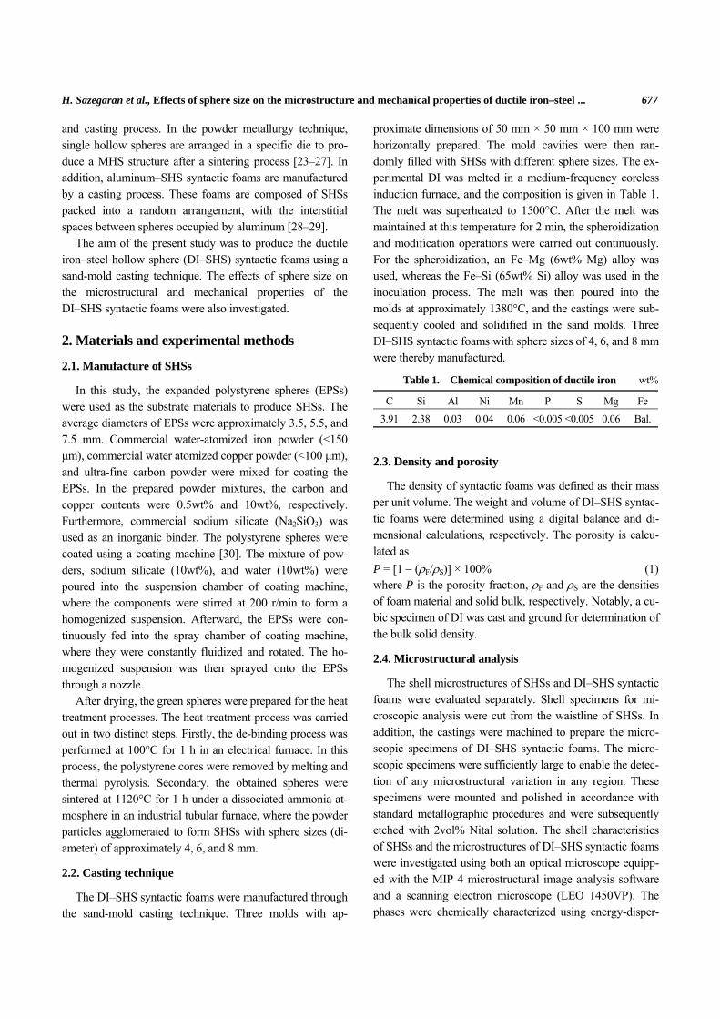
The shell characteristics of SHSs were known to depend on the powder specifications, the presence of additives and lubricants, the type of binder, the coating parameters, and the conditions of the de-binding and sintering processes [21–22]. An optical image of a cross-sectioned shell is shown in Fig. 1. In the optical images, the shell thickness and area fraction of the sintered powders were measured using microstructural image processing software. As a result,
the shell thickness of the SHSs was observed to vary from 190 to 250 μm, and the area fraction of the sintered powder region was measured to be approximately 50%.
Fig. 1. Optical image of a sphere shell.
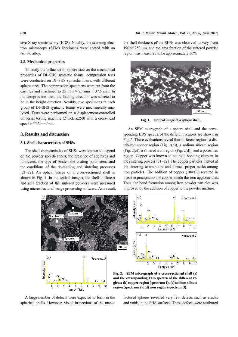
An SEM micrograph of a sphere shell and the corre-sponding EDS spectra of the different regions are shown in Fig. 2. These evaluations reveal four different regions: a dis-tributed copper region (Fig. 2(b)), a sodium silicate region (Fig. 2(c)), a sintered iron region (Fig. 2(d)), and a porosities region. Copper was known to act as a bonding element in the sintering process [31–32]. The copper particles melted at the sintering temperature and formed proper necks among iron particles. The addition of copper (10wt%) resulted in massive precipitation of copper inside the iron agglomerates. Thus, the bond formation among iron powder particles was improved by the addition of copper to the powder mixture.
A large number of defects were expected to form in the
spherical shells. However, visual inspections of the manu-factured spheres revealed very few defects such as cracks and voids in the SHS surfaces. These defects were attributed
Fig. 2. SEM micrograph of a cross-sectioned shell (a)and the corresponding EDS spectra of the different re-gions: (b) copper region (spectrum 1); (c) sodium silicateregion (spectrum 2); (d) iron region (spectrum 3).

H. Sazegaran et al., Effects of sphere size on the microstructure and mechanical properties of ductile iron–steel ... 679
to four causes: (a) using the commercial coarse iron powder; (b) the addition of copper powder; (c) performing the de-bonding and sintering processes in two separate steps; (d) using sodium silicate as an inorganic binder. These factors controlled the gas formation and exit during the heat-treat-ment processes and improved the bond formation during sintering. Hence, the number of defects was diminished in the sphere shells.
3.2. Density and porosity
In the case of syntactic foams, the packing density of hollow spheres and the porosity of sphere shells were known to be important parameters controlling the density and porosity [4,14]. The mean values of density and poros-ity of the DI–SHS syntactic foams are presented in Table 2. The average values of density range from 4824 to 5193 kg/m3, and the average values of porosity increase from 27% to 33% with decreasing spheres size. Notably, the po-rosity in steel–SHS syntactic foams has been reported to be approximately 50% [27]. The minimum of density and the maximum of porosity are observed in DI–SHS syntactic foam with 4 mm spheres size. As a result, the density in-creases and the porosity decreases by increasing the sphere size.
Table 2. Average values of the density and porosity of DI–SHS syntactic foams
Sphere size / mm Density / (kg·m–3) Porosity / %
4 4824 33
6 5089 29
8 5193 27
3.3. Microstructural evaluations
An SEM micrograph of the DI–SHS syntactic foam with an 8 mm sphere size is shown in Fig. 3. The microstructural evaluations reveal three different regions: a DI region, an SHS shell regions, and an interface region. In the case of steel-bar-reinforced DI composites, the formation of a diffu-sion bond between the two constituents was reported [33–34]. Although no diffusion bond was detected between the SHS shells and the DI matrix in the present work, the interface was thoroughly compatible. It was observed that the diffusion process was obstructed in the interface region by the presence of sodium silicate that remained on the sur-faces of the SHSs. By contrast, the sodium silicate restricted the diffusion of elements from the interface. Therefore, a transition interface was not formed between the DI matrix and the SHSs.
Fig. 3. SEM micrograph of the DI–SHS syntactic foam with 8 mm sphere size.
The optical microstructures of the DI matrixes are pre-sented in Fig. 4. As evident in this figure, the DI micro-structures consist of graphite nodules and cementite in the ferritic–pearlitic matrix. In the DI–SHS syntactic foam with 4 mm sphere size, no pearlite is recognizably observed in the matrix. As a result, the graphite morphology and the mi-crostructure of matrix depend on the sphere size. The varia-tions of nodule count and graphite circularity vs. sphere size are shown in Fig. 5. The nodule count of graphite clearly decreases and the graphite circularity increases with in-creasing sphere size. In addition, the results of the micro-structure analyses are presented in Table 3. With increasing sphere size, the area fraction of cementite decreases, and the fractions of graphite and pearlite increase.
In the DI–SHS syntactic foams, the thickness of DI be-tween the SHSs decreased with decreasing spheres size. The cooling rate of DI was known to increase with decreasing thickness [35–36]. Hence, the cooling rate increased with decreasing sphere size. The aforementioned variations in the graphite morphology and microstructure were attributed to the cooling rate. As evident in Table 3, the cooling rate (sphere size) influenced the area fractions of cementite, graphite, and pearlite. When the cooling rate increased (i.e., when the sphere size decreased), more cementite remained in the microstructure, whereas the graphite fraction de-creased.
3.4. Compression behavior
The compressional stress vs. strain curves of the DI–SHS syntactic foams with different sphere sizes are shown in Fig. 6. As evident in this figure, the manufactured foams do not demonstrate the typical compression behavior of foam ma-terials. The long plateau and the densification regions are not usually observed in such curves. However, steel–steel and aluminum–steel syntactic foams exhibit the typical stress vs. strain curves that include linear elastic, long pla-teau, and densification regions [27,29]. In the stress vs.

680 Int. J. Miner. Metall. Mater., Vol. 23, No. 6, June 2016
Fig. 5. Nodule count and graphite circularity vs. sphere size.
Table 3. Results of the microstructure analyses
Area fraction of phases / % Sphere size / mm
Cementite Graphite Pearlite
4 33.6 5.2 0.0
6 11.88 6.7 14.51
8 4.66 7.1 22.51
strain curves of the DI–SHS syntactic foams, the wavy pat-terns after the maximum stress are related to crack growth in the sphere shells. As a result, meaningful differences were recognized in the engineering stress vs. strain curves of the DI–SHS syntactic foams with different sphere sizes.
Fig. 6. Compression stress vs. strain curves for the DI–SHS syntactic foams with 4, 6, and 8 mm sphere sizes.
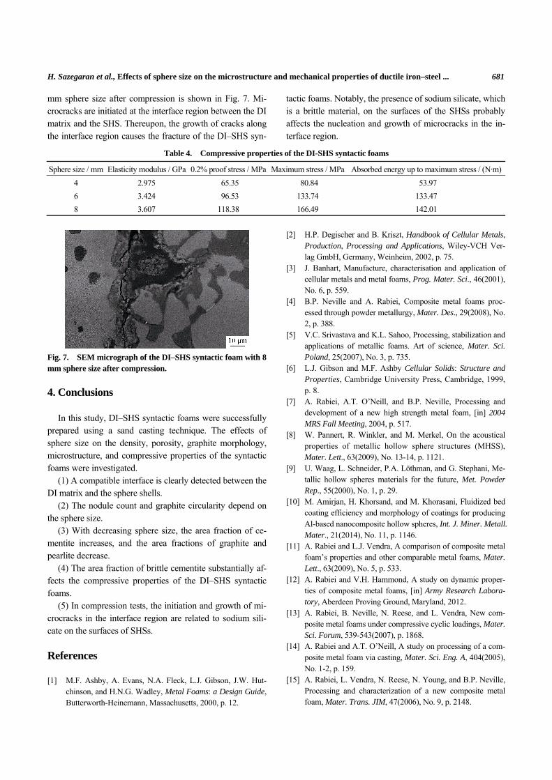
The compression test results are presented in Table 4. The results show that the sphere size is affected by the com-pression properties of the DI–SHS syntactic foams. The elasticity modulus, proof stress (0.2%), maximum compres-sion stress, and absorption energy to maximum stress are observed to decrease with decreasing sphere size. These be-haviors might be related to the brittle cementite in the mi-crostructure. The cementite fraction in the microstructures of the DI matrixes increased with decreasing sphere size, which resulted in the diminished compressional properties. An SEM micrograph of the DI–SHS syntactic foam with 8
Fig. 4. Optical images of ductile iron ma-trixes in the syntactic foams with 8 mm (a),6 mm (b), and 4 mm (c) sphere sizes.
H. Sazegaran et al., Effects of sphere size on the microstructure and mechanical properties of ductile iron–steel ... 681
mm sphere size after compression is shown in Fig. 7. Mi-crocracks are initiated at the interface region between the DI matrix and the SHS. Thereupon, the growth of cracks along the interface region causes the fracture of the DI–SHS syn-
tactic foams. Notably, the presence of sodium silicate, which is a brittle material, on the surfaces of the SHSs probably affects the nucleation and growth of microcracks in the in-terface region.
Table 4. Compressive properties of the DI-SHS syntactic foams
Sphere size / mm Elasticity modulus / GPa 0.2% proof stress / MPa Maximum stress / MPa Absorbed energy up to maximum stress / (N·m)
4 2.975 65.35 80.84 53.97
6 3.424 96.53 133.74 133.47
8 3.607 118.38 166.49 142.01
Fig. 7. SEM micrograph of the DI–SHS syntactic foam with 8 mm sphere size after compression.
4. Conclusions
In this study, DI–SHS syntactic foams were successfully prepared using a sand casting technique. The effects of sphere size on the density, porosity, graphite morphology, microstructure, and compressive properties of the syntactic foams were investigated.
(1) A compatible interface is clearly detected between the DI matrix and the sphere shells.
(2) The nodule count and graphite circularity depend on the sphere size.
(3) With decreasing sphere size, the area fraction of ce-mentite increases, and the area fractions of graphite and pearlite decrease.
(4) The area fraction of brittle cementite substantially af-fects the compressive properties of the DI–SHS syntactic foams.
(5) In compression tests, the initiation and growth of mi-crocracks in the interface region are related to sodium sili-cate on the surfaces of SHSs.
References
[1] M.F. Ashby, A. Evans, N.A. Fleck, L.J. Gibson, J.W. Hut-chinson, and H.N.G. Wadley, Metal Foams: a Design Guide, Butterworth-Heinemann, Massachusetts, 2000, p. 12.
[2] H.P. Degischer and B. Kriszt, Handbook of Cellular Metals, Production, Processing and Applications, Wiley-VCH Ver-lag GmbH, Germany, Weinheim, 2002, p. 75.
[3] J. Banhart, Manufacture, characterisation and application of cellular metals and metal foams, Prog. Mater. Sci., 46(2001), No. 6, p. 559.
[4] B.P. Neville and A. Rabiei, Composite metal foams proc-essed through powder metallurgy, Mater. Des., 29(2008), No. 2, p. 388.
[5] V.C. Srivastava and K.L. Sahoo, Processing, stabilization and applications of metallic foams. Art of science, Mater. Sci. Poland, 25(2007), No. 3, p. 735.
[6] L.J. Gibson and M.F. Ashby Cellular Solids: Structure and Properties, Cambridge University Press, Cambridge, 1999, p. 8.
[7] A. Rabiei, A.T. O’Neill, and B.P. Neville, Processing and development of a new high strength metal foam, [in] 2004 MRS Fall Meeting, 2004, p. 517.
[8] W. Pannert, R. Winkler, and M. Merkel, On the acoustical properties of metallic hollow sphere structures (MHSS), Mater. Lett., 63(2009), No. 13-14, p. 1121.
[9] U. Waag, L. Schneider, P.A. Löthman, and G. Stephani, Me-tallic hollow spheres materials for the future, Met. Powder Rep., 55(2000), No. 1, p. 29.
[10] M. Amirjan, H. Khorsand, and M. Khorasani, Fluidized bed coating efficiency and morphology of coatings for producing Al-based nanocomposite hollow spheres, Int. J. Miner. Metall. Mater., 21(2014), No. 11, p. 1146.
[11] A. Rabiei and L.J. Vendra, A comparison of composite metal foam’s properties and other comparable metal foams, Mater. Lett., 63(2009), No. 5, p. 533.
[12] A. Rabiei and V.H. Hammond, A study on dynamic proper-ties of composite metal foams, [in] Army Research Labora-tory, Aberdeen Proving Ground, Maryland, 2012.
[13] A. Rabiei, B. Neville, N. Reese, and L. Vendra, New com-posite metal foams under compressive cyclic loadings, Mater. Sci. Forum, 539-543(2007), p. 1868.
[14] A. Rabiei and A.T. O’Neill, A study on processing of a com-posite metal foam via casting, Mater. Sci. Eng. A, 404(2005), No. 1-2, p. 159.
[15] A. Rabiei, L. Vendra, N. Reese, N. Young, and B.P. Neville, Processing and characterization of a new composite metal foam, Mater. Trans. JIM, 47(2006), No. 9, p. 2148.

682 Int. J. Miner. Metall. Mater., Vol. 23, No. 6, June 2016
[16] Y. Alvandi-Tabrizi, D.A. Whisler, H. Kim, and A. Rabiei, High strain rate behavior of composite metal foams, Mater. Sci. Eng. A, 631(2015), p. 248.
[17] W. Yu, M.J. Xin, X. Liang, H.J. Li, Numerical investigation into effective elastic constants of MHS/EP composite, J. Mater. Eng. Perform., 21(2012), No. 10, p. 2038.
[18] C. Augustin and W. Hungerbach, Production of hollow spheres (HS) and hollow sphere structures (HSS), Mater. Lett., 63(2009), No. 13-14, p. 1109.
[19] T.J. Lim, B. Smith, and D.L. McDowell, Behavior of a ran-dom hollow sphere metal foam, Acta Mater., 50(2002), No. 11, p. 2867.
[20] M. Jaeckel and H. Smigilski, Coating of Polymeric Spheres with Particles, European Patent, DE 3724156, 1988.
[21] M. Behnam, A.S. Golezani, and M.M. Lima, Optimization of surface quality and shell porosity in low carbon steel hollow spheres produced by powder metallurgy, Powder Technol., 235(2013), p. 1025.
[22] M. Behnam, A.S. Golezani, and M.M. Lima, The effect of size and morphology of iron powder on shell density in low carbon steel hollow spheres, Powder Metall. Prog., 11(2011), No. 3-4, p. 185.
[23] M. Šupicová, R. Oriňáková, M. Kupková, and M. Kabátová, Electrolytical modification of Fe hollow spheres by Cu, Ni and Ni–Cu binary coatings, Surf. Coat. Technol., 195(2005), No. 2-3, p. 130.
[24] O. Andersen, U. Waag, L. Schneider, G. Stephani, and B. Kieback, Novel metallic hollow sphere structures, Adv. Eng. Mater., 2(2000), No. 4, p. 192.
[25] J.M. Koo, H. Araki, and S.B. Jung, Effect of Zn addition on mechanical properties of brass hollow spheres, Mater. Sci. Eng. A, 483-484(2008), p. 254.
[26] Y.D. Deng, L. Zhao, L. Liu, B. Shen, and W.B. Hu, Submi-crometer-sized hollow nickel spheres synthesized by auto-catalytic reduction, Mater. Res. Bull., 40(2005), No. 10, p.
1864. [27] A. Rabiei and M. Garcia-Avila, Effect of various parameters
on properties of composite steel foams under variety of load-ing rates, Mater. Sci. Eng. A, 564(2013), p. 539.
[28] L.J. Vendra and A. Rabiei, A study on Al–steel composite metal foam processed by casting, Mater. Sci. Eng. A, 465(2007), No. 1-2, p. 59.
[29] L.J. Vendra, J.A. Brown, and A. Rabiei, Effect of processing parameters on the microstructure and mechanical properties of Al–steel composite foam, J. Mater. Sci., 46(2011), No. 13, p. 4574.
[30] F. Bretschneider, B. Peter, and J. Brucker, Machine and Pro-cess for Producing a Free Flowing Product with a Coat, German Patent, DE 197 50 042 C2, 1999.
[31] W.D. Wong-Angel, L. Téllez-Jurado, J.F. Chávez-Alcalá, E. Chavira-Martínez, and V.F. Verduzco-Cedeño, Effect of copper on the mechanical properties of alloys formed by powder metallurgy, Mater. Des., 58(2014), p. 12.
[32] A. Simchi, Effect of C and Cu addition on the densification and microstructure of iron powder in direct laser sintering process, Mater. Lett., 62(2008), No. 17-18, p. 2840.
[33] M. Kazemi, A.R. Kiani-Rashid, and A. Nourian, Impact toughness and microstructure of continuous medium carbon steel bar-reinforced cast iron composite, Mater. Sci. Eng. A, 559(2013), p. 135.
[34] M. Kazemi, A.R. Kiani-Rashid, A. Nourian, and A. Babak-hani, Investigation of microstructural and mechanical proper-ties of austempered steel bar-reinforced ductile cast iron composite, Mater. Des., 53(2014), p. 1047.
[35] M. Górny and E. Tyrała, Effect of cooling rate on micro-structure and mechanical properties of thin-walled ductile iron castings, J. Mater. Eng. Perform., 22(2013), No. 1, p. 300.
[36] F. Binczyk, A. Kowalski, and J. Furmanek, The effect of cooling rate on the microstructure of nodular cast iron, Arch. Foundry Eng., 7(2007), No. 2, p. 115.