effects of fouling and operational conditions in pre …
TRANSCRIPT

BRAZILIAN JOURNAL OF PETROLEUM AND GAS | v. 11 n. 2 | p. 079-089 | 2017 | ISSN 1982-0593
79
EFFECTS OF FOULING AND OPERATIONAL CONDITIONS IN PRE-HEAT TRAIN HEAT EXCHANGERS DESIGN
a Nakao, A.;
a Queiroz, E. M. 1
a Federal University of Rio de Janeiro (UFRJ), School of Chemistry, Rio de Janeiro – RJ, Brazil
Received: 16.02.2017 / Revised: 23.03.2017 / Accepted: 24.03.2017 / Published on line: 18.07.2017
ABSTRACT Heat exchanger traditional design approaches include the use of fixed fouling factors in the overall heat transfer coefficient. These values do not take into account operational conditional influences, which are very important to the fouling process. This work uses a methodology that incorporates dynamic effects of fouling in the design of pre-heat train heat exchanges, using the HTRI® software to obtain a better heat exchanger design for a specified fouling factor. The software solves a differential algebraic equation system, which describes equipment dynamics in a specified operational period, and evaluates the fouling resistance according to a fouling rate model. The fouling dynamic is described by the Ebert-Panchal Modified model, which is used for crude oil streams in pre-heat trains. The application of the methodology is shown in typical pre-heat train heat conditions, in exchangers without loop control. The examples highlight the temperature effects in fouling formation and, then, in the heat exchanger design.
KEYWORDS fouling; shell and tubes heat exchanger design; fouling rate model; crude oil; pre-heat train
1 To whom all correspondence should be addressed.
Address: Universidade Federal do Rio de Janeiro (UFRJ), Escola de Química, Centro de Tecnologia, Bloco E, Ilha do Fundão, Rio de Janeiro – RJ, Brasil. ZIP Code: 21949-900 | e-mail: [email protected] doi:10.5419/bjpg2017-0007

BRAZILIAN JOURNAL OF PETROLEUM AND GAS | v. 11 n. 2 | p. 079-089 | 2017 | ISSN 1982-0593
80
1. INTRODUCTION
In industrial processes, a reduction in energy consumption is a high-priority goal. In oil refineries, for example, the heating process of large amounts of crude oil in pre-heat trains is supplemented by the combustion of fossil fuels.
Process streams, especially oil streams, are susceptible to fouling. This phenomenon can lead to a 30% decrease in the overall operational heat transfer coefficient and in heat exchanger efficiency during the operational period. Polley et al. (2002) reported that fouling-related costs in a heat exchanger of a pre-heat train, designed using a recommended constant value for the fouling resistance, can reach up to US$ 100 000.00, after three months processing 100000 bbl of oil. According to Radhakrishnan et al. (2007), the annual lost due fouling in the US and UK reaches US$ 16.5 billion. According to Kashani et al. (2012), fossil fuel consumption related to fouling processes to compensate thermal losses represents 0.25% of the gross national product of industrialized countries. Therefore, heat exchanger performance is a relevant variable in the cost analysis process. Moreover, additional fossil fuel consumption results in greater carbon dioxide emissions (Polley et al., 2002). Hence, fouling effects have a significant impact on initial and operational heat exchanger costs. Based on the above mentioned, these effects must be taken into account to reach a higher thermal efficiency, reducing losses due to fuel consumption and greenhouse gas emissions.
The classic approach to include fouling effects in the project involves the use of a constant value for the fouling factor proposed by the Tubular Exchanger Manufacturer Association –TEMA (2007) in the calculation of the overall heat transfer coefficient (Hesselgreaves, 2002). This fixed value does not include operational effects that can promote or mitigate fouling formation and does not take into account the dynamic nature of the fouling process.
To overcome this issue, new design procedures have been developed. Among those, only a few heat exchangers design methodologies using fouling rate models in the overall heat transfer coefficient calculation. In 2002, Hesselgreaves (2002) discussed the use of fixed values for fouling factors recommended by TEMA. The
implementation of these values can result in a 40% increase in heat exchanger surface area. This excess increases equipment cost and, in the beginning of the operation, can demand a reduction in flow rate to reach the design conditions, which can enhance the fouling formation process.
2. FOULING RATE MODELS FOR OIL STREAMS
Fouling rate models are based on Kern and Seaton’s proposal (Kern & Seaton, 1959). This proposal relates the rate of fouling accumulation with a term representing fouling formation, linked to operational conditions, to promote de fouling process (for example, surface temperature, concentration of potential substances that can form the deposits), and with another process representing suppressing/removing, related to the fouling layer and to the shear stress over its surface (Shen et al., 2015). Based on this proposal, many authors have developed different models for various fouling types.
A simple deployment of this proposal is based on a constant formation rate and a removal rate proportional to the fouling quantity. This physical situation leads to the asymptotic model, described in Equation 1.
(1)
Where is the asymptotic fouling resistance value
and is a time constant related to the fouling phenomena. For oil streams with constant heat flux, Hewitt (1998) proposed the following relation between the asymptotical fouling value and the fluid velocity :
(2)
The value for the factor can be calculated using a previously known value with Equation 3:
(3)

BRAZILIAN JOURNAL OF PETROLEUM AND GAS | v. 11 n. 2 | p. 079-089 | 2017 | ISSN 1982-0593
81
Where is a known value for a known velocity
and is a parameter related to the fouling type. The asymptotic behavior is observed in some pre-heat train exchangers, but is not general for the entire the train. It is also important to point out that the fouling surface temperature is very important in the fouling resistance value, as it will be shown in the following, and this relation is not represented in Equation (2).
Another type of model is the rate model, also called threshold model. Focusing on crude oil streams, Ebert and Panchal (1995) presented a rate model that describes fouling in a flow inside tubes as a consequence of two competitive mechanisms: (i) the first one makes a relation between the fouling formation and a chemical reaction model; and (ii) the second relates fouling reduction with the presence of shear stress over the fouling surface. Equation (4) shows its form:
(4)
Where is the thermal fouling resistance, is the Reynolds number of the tube’s side flow, is the activation energy for fouling formation, is the universal gas constant, is the film temperature, is the shear stress over the fouling surface, and , and are empirical constants, which are functions of the fluid. Therefore, there are operational conditions where the effects from both terms balance each other and there is a no fouling condition (Polley et al., 2002). These conditions can be represented by a curve in a film temperature versus fluid flow velocity plot. This curve defines a threshold between two regions, named fouling envelop (Figure 1). Above the
threshold there is a region where there is fouling formation and, below, there is a region with no fouling conditions. Based on this plot, the designer can predict operational conditions where heat exchangers operate in a no fouling condition, as suggested by Butterworth (2002).
After Ebert and Panchal’s proposal (Ebert & Panchal, 1995), many researchers applied their equation in many experimental data. Due to result inconsistencies, numerous adaptations of the model have been proposed for different operational condition ranges to better describe operational behavior (Wilson et al., 2015). For example, using refinery data, Lestina and Zettler (2014) suggested the use of the fouling surface temperature (Ts) instead of the film temperature in Equation (4). Also, the number of parameters has been decreased by using the Prandlt number. Therefore, these proposals have led to the following equation (Wilson et al., 2015):
(5)
Where is the fluid Prandlt number and Ts is the fouling surface temperature. This equation represents the so called Ebert-Panchal Modified model.
3. FOULING INCLUSION IN HEAT EXCHANGERS DESIGN PROCEDURE
According to Caputo et al. (2011), there are two different approaches for heat exchanger design procedures including fouling effects: (i) traditional methodology, using TEMA’s fouling factors; and (ii) the use of fouling rate models to achieve results closer to real operational behavior.
Butterworth (2002) presented a work about fluid velocity effects in fouling thermal resistance calculation for shell and tubes heat exchanger designs using a fouling rate model. The author highlighted that traditional procedure results in oversized equipment, which works well as a safety choice, but oversized equipment normally promotes fouling phenomena because it needs lower velocities to achieve the desired performance. As a consequence, there is a fouling
Figure 1. Fouling Envelop (Costa et al.,2011).
BRAZILIAN JOURNAL OF PETROLEUM AND GAS | v. 11 n. 2 | p. 079-089 | 2017 | ISSN 1982-0593
82
formation greater than expected. Butterworth (2002) tried to include surface temperature effects in the model, but the procedure showed an increase in complexity and in time consumption to solve the mathematical calculations, although yielding a better result. In this work, some ranges of temperature and fluid velocity were identified as no fouling operational conditions, where the traditional project should be used without fouling resistance consideration.
Wilson et al. (2002) presented an alternative approach for heat exchanger design for heat exchangers in pre-heating trains. They used the Ebert-Panchal semi-empirical model to substitute the fixed value of TEMA’s fouling factor, and updated the Poddar plot method (Poddar & Polley, 1996). They incorporated the threshold line in the Poddar plot to identify heat exchanger design, or configurations in which fouling is minimized. The Ebert-Panchal rate model includes the effects of temperature and fluid velocity to predict fouling rates. The use of this model demonstrates the importance of considering these operational factors in design procedure.
Nesta and Bennett (2004) suggest a different approach in designing shell and tubes heat exchangers, the no-foul design method. Basically, they proposed making the design using a no fouling operational condition. This design produced cheaper exchangers, but the method resulted in greater uncertainties in predicting the no fouling region.
Caputo et al. (2011) developed a heat exchanger design procedure called joint optimization using genetic algorithm. This work incorporated the cleaning step in the total equipment cost. To consider the fouling effects, it assesses a maximum allowable fouling resistance. The time for the equipment to reach this value defines the cleaning step. This design procedure assures the existence of an excess surface area until the stop for cleaning. The authors tested this procedure designing exchangers using distilled water and raw water.
4. DESIGN METHODOLOGY
The present work adopts a design methodology consisting of three steps: (i) shell and tubes heat
exchanger design using a fouling factor (traditional procedure); (ii) equipment dynamic simulation during a specified operational period using a fouling rate model; and (iii) predicted operational conditions check during the simulated operational period. If over the operational period the heat exchanger does not respect the design constraints, there will be a new design search. In this new search, the fouling factor is updated using a new value calculated by the fouling rate model during the dynamic simulation.
In step (i), the HTRI design tool is used to obtain a shell and tubes heat exchanger design candidate for the required service based on a specified fouling resistance (e.g. TEMA value in the first iteration). To run this step, a set of parameters must be defined by the engineer: fluid allocation (tube or shell), materials (shell and tube among others), shell and head types, baffle type and cut, tube pitch ratio, tube layout pattern, outer tube diameter and tube wall thickness. The parameters searched for the design by the software are: inner shell diameter, total number of tubes, number of tube passes, tube length, and baffle spacing.
For steps (ii) and (iii), the mathematical models were implemented in the MATLAB® environment. The routines were then connected to the HTRI Xchanger Suite Educational® 6.0 (Heat Transfer Research Institute) to transfer the data exchange along the iterations more easily. In these routines, the dynamic aspect involves a system with differential and algebraic equations, where the solution is obtained by using the tool Dassl Solver (Petzold, 1983). Figure 2 shows a flowchart of the methodology.
4.1 Basic equations
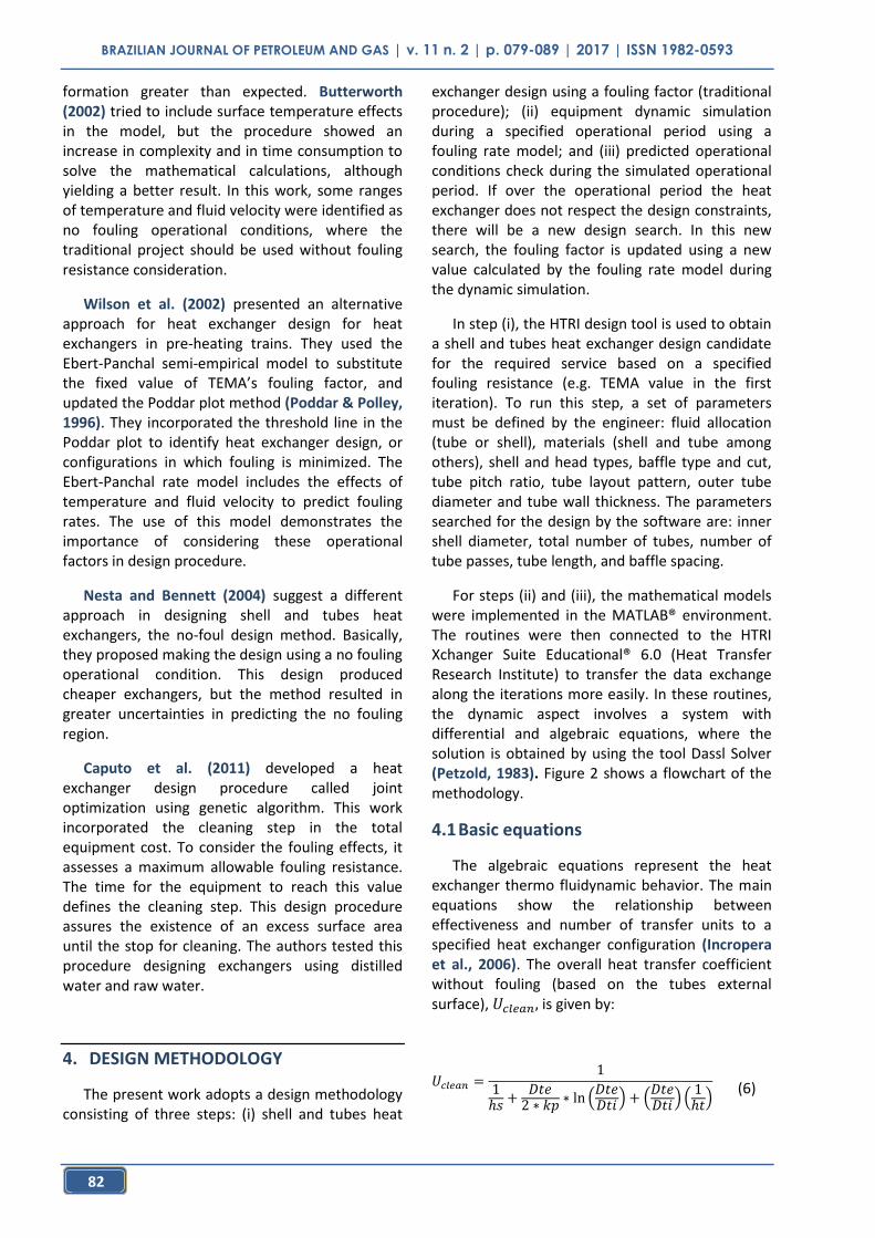
The algebraic equations represent the heat exchanger thermo fluidynamic behavior. The main equations show the relationship between effectiveness and number of transfer units to a specified heat exchanger configuration (Incropera et al., 2006). The overall heat transfer coefficient without fouling (based on the tubes external surface), is given by:
(6)

BRAZILIAN JOURNAL OF PETROLEUM AND GAS | v. 11 n. 2 | p. 079-089 | 2017 | ISSN 1982-0593
83
Where is the external tube diameter, is the internal tube diameter, is the wall thermal condutivity, is the shell side heat transfer coefficient, and is the tube side heat transfer coefficient. The fouling effects are added and represented by its total thermal resistance (RRf):
(7)
Where Ud is the overall heat transfer coefficient with fouling, based also on the tubes’ external surfaces. The total fouling thermal resistance is related to the fouling resistance inside the tubes ( ), based on the surface where fouling occurs, by:
(8)
The Ebert-Panchal modified model is a function
of fouling surface temperature and fluid flow velocity over this surface. As the temperature changes along the equipment, the rate also changes and the procedure uses an arithmetical media between the values in both sides of the exchanger. The surface temperatures in both sides of the equipment, with 1 representing the cold side and 2 the hot side, are calculated by:
(9)
(10)
The thermal resistances in Equations (9) and (10) are calculated by the following equations:
Fouling resistance:
(11)
Figure 2. Design proposal methodology algorithm.
BRAZILIAN JOURNAL OF PETROLEUM AND GAS | v. 11 n. 2 | p. 079-089 | 2017 | ISSN 1982-0593
84
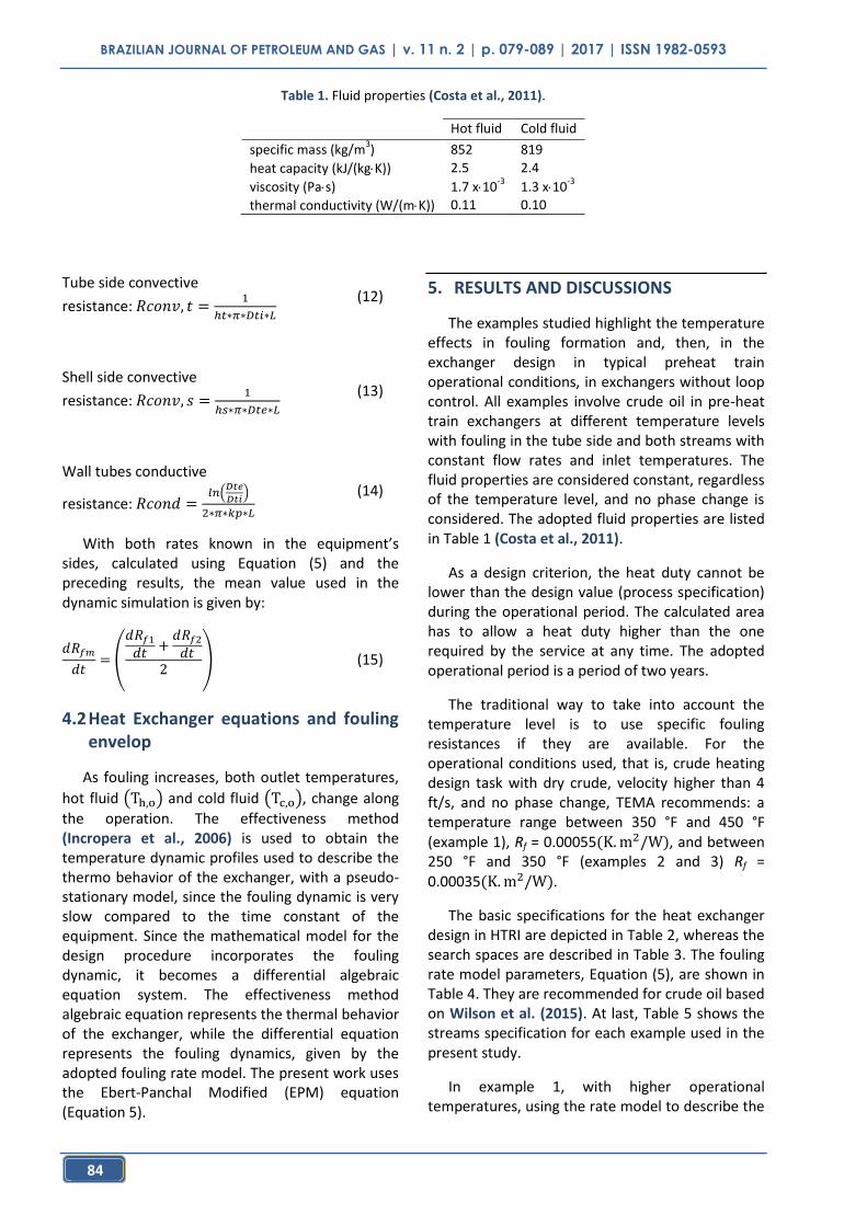
Tube side convective
resistance:
(12)
Shell side convective
resistance:
(13)
Wall tubes conductive
resistance:
(14)
With both rates known in the equipment’s sides, calculated using Equation (5) and the preceding results, the mean value used in the dynamic simulation is given by:
(15)
4.2 Heat Exchanger equations and fouling envelop
As fouling increases, both outlet temperatures,
hot fluid and cold fluid , change along
the operation. The effectiveness method (Incropera et al., 2006) is used to obtain the temperature dynamic profiles used to describe the thermo behavior of the exchanger, with a pseudo-stationary model, since the fouling dynamic is very slow compared to the time constant of the equipment. Since the mathematical model for the design procedure incorporates the fouling dynamic, it becomes a differential algebraic equation system. The effectiveness method algebraic equation represents the thermal behavior of the exchanger, while the differential equation represents the fouling dynamics, given by the adopted fouling rate model. The present work uses the Ebert-Panchal Modified (EPM) equation (Equation 5).
5. RESULTS AND DISCUSSIONS
The examples studied highlight the temperature effects in fouling formation and, then, in the exchanger design in typical preheat train operational conditions, in exchangers without loop control. All examples involve crude oil in pre-heat train exchangers at different temperature levels with fouling in the tube side and both streams with constant flow rates and inlet temperatures. The fluid properties are considered constant, regardless of the temperature level, and no phase change is considered. The adopted fluid properties are listed in Table 1 (Costa et al., 2011).
As a design criterion, the heat duty cannot be lower than the design value (process specification) during the operational period. The calculated area has to allow a heat duty higher than the one required by the service at any time. The adopted operational period is a period of two years.
The traditional way to take into account the temperature level is to use specific fouling resistances if they are available. For the operational conditions used, that is, crude heating design task with dry crude, velocity higher than 4 ft/s, and no phase change, TEMA recommends: a temperature range between 350 °F and 450 °F (example 1), Rf = 0.00055 , and between 250 °F and 350 °F (examples 2 and 3) Rf = 0.00035 .
The basic specifications for the heat exchanger design in HTRI are depicted in Table 2, whereas the search spaces are described in Table 3. The fouling rate model parameters, Equation (5), are shown in Table 4. They are recommended for crude oil based on Wilson et al. (2015). At last, Table 5 shows the streams specification for each example used in the present study.
In example 1, with higher operational temperatures, using the rate model to describe the
Table 1. Fluid properties (Costa et al., 2011).
Hot fluid Cold fluid
specific mass (kg/m3) 852 819
heat capacity (kJ/(kgK)) 2.5 2.4
viscosity (Pas) 1.7 x10⁻³
1.3 x10⁻³
thermal conductivity (W/(mK)) 0.11 0.10

BRAZILIAN JOURNAL OF PETROLEUM AND GAS | v. 11 n. 2 | p. 079-089 | 2017 | ISSN 1982-0593
85
fouling behavior, the solutions were obtained after twenty iterations. Results are shown in Table 6. EPM is the result obtained with the rate model, whereas TEMA is the result of the traditional procedure, adopting the Rf value coming from the TEMA Manual. Rf design is the value used in the HTRI design, which obtained the exchange features presented in the table, and Rf simulated is the Rf value at the end of two years of operational time. Comparing the calculated heat transfer areas, the
EPM result shows one area 400% higher. This difference comes from the significant different values for the Rf, denoting that the TEMA value is underestimated in this temperature level.
In example 2, intermediate temperature level, the rate model solution was obtained with three iterations. The calculated heat transfer areas are quite similar with a difference of approximately 15%, which denotes that the TEMA Rf value is
Table 2. Basic specifications of the heat exchangers.
Specification
TEMA type AES baffle type single segmental baffle cut (%) 25 tube pitch ratio 1.25 tube layout triangular outer tube diameter (mm) 19.05 tube thickness (mm) 2.1
Table 3. Input specifications in the HTRI design mode.
Specification
number of tube passes 1, 2, 4, 6, … tube length 3.5;4.0; 4.5; 5.0; 5.5 and 6.0 overdesign (%) 0 to 10 tube side velocity bounds (m/s) 1.0 to 3.0 shell side velocity bounds (m/s) 0.25 to 2.0
Table 4. Fouling Rate model parameters, Eq. (5).
Parameter
(m2K/J) 127.7
Ea (kJ/mol) 76
(m2.K/(JPa)) 3.44 x10
-12
Table 5. Stream specification.
Fluid Hot Stream Cold Stream
Crude Oil
Flowrate (kg/s) 60 65 Allowed Head Loss (kPa) 70 70
Fouling No Yes Alocation Shell Tubes
Example 1
T inlet (C)
231 155
Example 2
215 140
Example 3
180 115

BRAZILIAN JOURNAL OF PETROLEUM AND GAS | v. 11 n. 2 | p. 079-089 | 2017 | ISSN 1982-0593
86
reasonable in this temperature range in the context of the adopted rate model.
In example 3, lower temperature level, using the TEMA fouling resistance value, the exchanger should have an area 38% higher than the one calculated using the rate model. In this temperature level, the exchanger operates in the no fouling region, part of the concept of the rate model.
The difference between iteration numbers in the three examples in the EPM results can be explained based on the fouling resistance values calculated. As the surface temperature increases, fouling rate also increases. The calculated heat
exchanger becomes bigger, reducing the flow velocity in the tube side, which also increases the fouling rate. These two effects combined increase the fouling resistance in each iteration, leading to more iterations before reaching convergence.
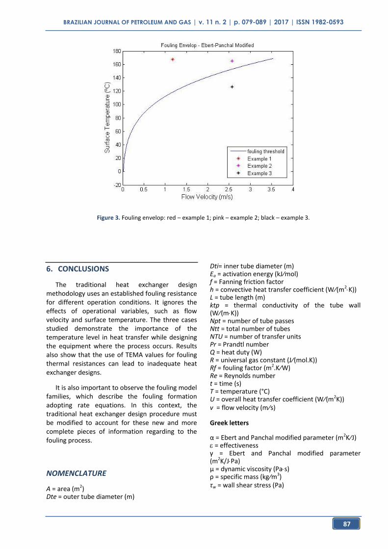
Figure 3 shows the fouling envelop with the three operational conditions for each example. The red spot represents example 1, the pink one example 2, and the black spot example 3. As expected, example 1 has a lower flow velocity and is far from the fouling threshold inside the fouling region. Example 2 has a bigger flow velocity and is next to the fouling curve. Example 3 is in the no fouling region.
Table 6. Example 1 - Heat exchanger design solutions: design variables.
EPM TEMA
design 0.00833 0.00055 simulated 0.00795 ---
area (m2) 695.3 138.8
total number of tubes 2160 426 number of tube passes 6 2
shell diameter (m) 1.27 0.85 tube length (m) 5.5 5,5
baffle spacing (m) 25 25 overdesign (%) 0.2 6.5
Table 7. Example 2 - Heat exchanger design solutions: design variables.
EPM TEMA
design 0.00018 0.00035 simulated 0.00018 ---
area (m2) 73.9 84.6
total number of tubes 358 358 number of tube passes 2 2
shell diameter (m) 0.54 0.54 tube length (m) 3.5 4
baffle spacing (m) 0.333 0.405 overdesign (%) 7.9 5.4
Table 8. Example 3 - Heat exchanger design solutions: design variables.
EPM TEMA
design 0 0.00035 simulated 0 ---
area (m2) 84.6 116.6
total number of tubes 358 394 number of tube passes 2 2
shell diameter (m) 0.54 0,56 tube length (m) 4 5
baffle spacing (m) 0.404 0.426 overdesign (%) 8.66 3.17
BRAZILIAN JOURNAL OF PETROLEUM AND GAS | v. 11 n. 2 | p. 079-089 | 2017 | ISSN 1982-0593
87
6. CONCLUSIONS
The traditional heat exchanger design methodology uses an established fouling resistance for different operation conditions. It ignores the effects of operational variables, such as flow velocity and surface temperature. The three cases studied demonstrate the importance of the temperature level in heat transfer while designing the equipment where the process occurs. Results also show that the use of TEMA values for fouling thermal resistances can lead to inadequate heat exchanger designs.
It is also important to observe the fouling model families, which describe the fouling formation adopting rate equations. In this context, the traditional heat exchanger design procedure must be modified to account for these new and more complete pieces of information regarding to the fouling process.
NOMENCLATURE
A = area (m2) Dte = outer tube diameter (m)
Dti= inner tube diameter (m) Ea = activation energy (kJ⁄mol) f = Fanning friction factor h = convective heat transfer coefficient (W⁄(m2
K)) L = tube length (m) ktp = thermal conductivity of the tube wall (W⁄(mK)) Npt = number of tube passes Ntt = total number of tubes NTU = number of transfer units Pr = Prandtl number Q = heat duty (W) R = universal gas constant (J⁄(mol.K)) Rf = fouling factor (m2.K⁄W) Re = Reynolds number t = time (s) T = temperature (°C) U = overall heat transfer coefficient (W⁄(m2K)) v = flow velocity (m⁄s)
Greek letters
= Ebert and Panchal modified parameter (m2K⁄J) = effectiveness = Ebert and Panchal modified parameter (m2K/JPa) μ = dynamic viscosity (Pas) ρ = specific mass (kg⁄m3) τw = wall shear stress (Pa)
Figure 3. Fouling envelop: red – example 1; pink – example 2; black – example 3.

BRAZILIAN JOURNAL OF PETROLEUM AND GAS | v. 11 n. 2 | p. 079-089 | 2017 | ISSN 1982-0593
88
Subscripts
avg = average c = cold stream clean = no fouled d = design dirty condition foul = fouled h = hot stream i = inlet o = outlet s = shell t = tube
7. REFERENCES
Butterworth, D. Design of shell-and tube heat exchangers when the fouling depends on local temperature and velocity. Applied Thermal Engineering, v.22, p.789-801, 2002. https://doi.org/10.1016/S1359-4311(02)00025-X
Caputo, A. C.; Pelagagge, P. M.; Salini, P. Joint economic optimization of heat exchanger design and maintenance policy. Applied Thermal Energy, v. 31, p. 1381-1392, 2011. https://doi.org/10.1016/j.applthermaleng.2010.12.033
Costa, A. L.H.; Tavares, V. B. G.; Borges, J. L.; Queiroz, E. M.; Pessoa, F. L.P.; Liporace, F. S; Oliveira, S. G. Parameter Estimation of Fouling Models in Crude oil Preheat Trains. Proceedings of International Conference on Heat Exchanger Fouling and Cleaning, Crete Island, Greece, 2011.
Ebert, W.; Panchal, C. B. Analysis of Exxon crude oil slip stream coking data. Proceedings of Mitigation of Fouling in Industrial Heat Exchangers, San Luis Obispo, USA, p.451-460, 1995.
Hesselgreaves, J. E. An approach to fouling allowances in the design of compact heat exchangers. Applied Thermal Engineering, v.22, 755-762, 2002. https://doi.org/10.1016/S1359-
4311(02)00033-9
Hewitt, G. F. Heat Exchanger Design Handbook. Begell House, 1998.
Incropera, F. P.; DeWiti, D.P.; Bergman, T.L.; Lavine, A. S. Fundamentos de Transferência de Calor e de Massa. Rio de Janeiro: LTC, 6ª Ed., 2005. (in Portuguese)
Kashani, M. N.; Aminian, J.; Shahhosseini, S.; Farrokhi, M. Dynamic crude oil fouling prediction in industrial preheaters using optimized ANN based moving window technique. Chemical Engineering Research and Design, v. 90, pp. 938-949, 2012. https://doi.org/10.1016/j.cherd.2011.10.013
Kern, D. Q., Seaton, R. E., A Theoretical Analysis of Thermal Surface Fouling. British Chemical Engineering, 4, p. 258-265, 1959.
Lestina, T, G.; Zettler H. U. Crude Oil Fouling Research: HTRI’s Perspective. Heat Transfer Engineering, v.35, p.217-223, 2014. https://doi.org/10.1080/01457632.2013.825153
Nesta, J.; Bennet, C.A. Reduce fouling in shell-and-tube heat exchangers. Hydrocarbon Processing, July 2004, p. 77 -82, 2004.
Poddar, T. K., Polley, G. T. Heat exchanger design through parameter plotting. Transactions of the Institution of Chemical Engineers, v. 74 (Part A), p. 849–852 (1996).
Petzold, L. R. DASSL: Differential algebraic
system solver. Technical Report Category #D2A2,
Sandia National Laboratories, Livermore, California,
1983.
Polley, G. T.; Wilson, D. I.; Yeap, B. L.; Pugh, S. J.; Evaluation of laboratory crude oil threshold fouling data for application to refinery pre-heat trains. Applied Thermal Engineering. v. 22, p. 777-788, 2002. https://doi.org/10.1016/S1359-4311(02)00023-6
Radhakrishnan, V. R.; Ramasamy, M. Z., Zabiri, H.; DoThanh, V.; Tahir, N.M.; Mukhtar, H.; Hamid, M. R.; Rmali, N. Heat exchanger fouling model and preventive maintenance scheduling tool. Applied Thermal Engineering, v. 27, p. 2791-2802, 2007. https://doi.org/10.1016/j.applthermaleng.2007.02.009
Shen, C.; Cirone, C.; Jacobi, A. M.; Wang, X. Fouling of enhanced tubes for condensers used in cooling tower systems: A literature review. Applied Thermal Engineering, v.79, pp. 74-79, 2015. https://doi.org/10.1016/j.applthermaleng.2015.01.014
TEMA, Standards of the Tubular Exchanger Manufacturers Association, 9th Edition, 2007.

BRAZILIAN JOURNAL OF PETROLEUM AND GAS | v. 11 n. 2 | p. 079-089 | 2017 | ISSN 1982-0593
89
Wilson, D. I.; Polley, G. T.; Pugh, S. J. Ten years of Ebert, Panchal and the “threshold fouling” concept. Heat Exchanger Fouling and Cleaning, v. RP2, Article 6, Kloster Irsee, Germany, June 5 - 10, 2005.
Wilson, D. I.; Ishiyama, E. M.; Polley, G. T. Twenty years of Ebert and Panchal - What next?. Heat Exchanger Fouling and Cleaning Conference, Dublin, Ireland, 2015.