effect of surfactants on drop stability and thin film drainage · 1 effect of surfactants on drop...
TRANSCRIPT
1
Effect of Surfactants on Drop Stability and Thin Film Drainage
Krassimir D. Danov Laboratory of Physical Chemistry and Engineering, Faculty of Chemistry, University of Sofia,
1 J. Bourchier Ave., 1164, Sofia, Bulgaria
Abstract. The stability of suspensions/emulsions is under consideration. Traditionally consideration of colloidal systems is based on inclusion only Van-der-Waals (or dispersion) and electrostatic components, which is refereed to as DLVO (Derjaguin-Landau-Verwey-Overbeek) theory. It is shown that not only DLVO components but also other types of the inter-particle forces may play an important role in the stability and colloidal systems. Those contributions are due to hydrodynamic interactions, hydration and hydrophobic forces, steric and depletion forced, oscillatory structural forces. The hydrodynamic and colloidal interactions between drops and bubbles emulsions and foams are even more complex (as compared to that of suspensions of solid particles) due to the fluidity and deformability of those colloidal objects. The latter two features and thin film formation between the colliding particles have a great impact on the hydrodynamic interactions, the magnitude of the disjoining pressure and on the dynamic and thermodynamic stability of such colloidal systems.
1 Introduction Colloidal systems and dispersions are of great importance in many areas of human activity such as oil recovery, coating, food and beverage industry, cosmetics, medicine, pharmacy, environmental protection etc. They represent multi-component and multiphase (heterogeneous) systems, in which at least one of the phases exists in the form of small (Brownian) or large (non-Brownian) particles (Hetsroni 1982, Russel et al. 1989, Hunter 1993). One possible classification of the colloids is with respect to the type of the continuous phase (dispersions with solid continuous phase like metal alloys, rocks, porous materials, etc. will not be consider). Gas continuous phase. Examples for liquid-in-gas dispersions are the mist and the clouds. Smoke, dust and some aerosols are typical solid-in-gas dispersions (Britter and Griffiths 1982, Arya 1999). Liquid continuous phase. Gas-in-liquid dispersions are the foams or the boiling liquids (Prud’homme and Khan 1996, Exerova and Kruglyakov 1998). Liquid-in-liquid dispersions are usually called emulsions. The emulsions exist at room temperature when one of the liquids is immiscible or mutually immiscible in the other, e.g. water, hydrocarbon and fluorocarbon oils and liquid metals (Hg and Ga). Many raw materials and products in food and petroleum industries exist in the form of oil-in-water or water-in-oil emulsions (Shinoda and Friberg 1986, Sjoblom 1996, Binks 1998). The solid-in-liquid dispersions are termed suspensions or sols. The pastes, paints, dyes, some glues and gels are highly concentrated suspensions (Schramm 1996).
Published in: Fluid Mechanics of Surfactant and Polymer Solutions (CISM Cources and Lectures No. 463) V.M. Starov and I.B. Ivanov, Eds., Springer, New York, 2004; pp. 1-38.

2
The investigations of the stability of dispersions against flocculation and coalescence are of crucial importance for the development of new complex fluids. Generally, the stabilizing factors are the repulsive surface forces, the particle thermal motion, the hydrodynamic resistance of medium and the high surface elasticity of fluid particles and films. On the opposite, the factors destabilizing dispersions are the attractive surface forces, the low surface elasticity and gravity, turbulence and other external forces tending to separate the phases. The nonionic and ionic surfactants, polymers and protein blends are widely used in practice to control the surface elasticity and mobility and the magnitude of the surface forces (Adamson and Gast 1997). The stability of suspensions containing solid particles are treated in the framework of the Derjaguin–Landau–Verwey–Overbeek (DLVO) theory, which accounts for the electrostatic and van der Waals interactions between the particles (Verwey and Overbeek 1948, Derjaguin 1989). In the past decades it has been shown that other types of inter-particle forces may also play an important role in the stability of dispersions – hydrodynamic interactions, hydration and hydrophobic forces, steric and depletion forces, oscillatory structural forces, etc. The hydrodynamic and molecular interactions between surfaces of drops and bubbles in emulsion and foam systems (compared to that of suspensions of solid particles) are more complex due to the particles fluidity and deformability. These two features and the possible thin film formation between the colliding particles have a great impact on the hydrodynamic interactions, the magnitude of the disjoining pressure and on the dynamic and thermodynamic stability of such systems (Ivanov and Dimitrov 1988, Danov et al. 2001, Kralchevsky et al. 2002). 2 Hydrodynamic modeling of surfactant solutions. Interfacial dynamics A solid (liquid) particle, which moves in a liquid medium, induces a motion of fluid in a hydrodynamic layer around itself and experiences hydrodynamic friction force from the surrounding continuous phase. When the hydrodynamic layers of two colliding particles overlap each other long-range hydrodynamic interactions among them due to the viscous friction appear. The quantitative description of this interaction is based on the classical laws of mass conservation and momentum balance for the bulk phases. If t is time, ∇ is the spatial gradient operator, ρ is the mass density, v is the local mass average velocity, P is the hydrodynamic stress tensor, Pb is the body force tensor and f ≡ ∇⋅Pb is the body force vector per unit volume acting on the fluid, then the mass and momentum balance equations read (Batchelor 1967, Landau and Lifshitz 1984):
0)( =⋅∇+ vρ∂ρ∂t
, 0)()(b =−−⋅∇+ PPvvv ρ
∂ρ∂t
. (1)
For some special kind of magnetic-liquids and liquid crystals the symmetry of the hydrodynamic stress tensor, P, breaks down (Slattery 1978). In the case of classical fluids P is a symmetric tensor – there is not micro-moments acting on the fluid element. The stress tensor P becomes a superposition of two contributions – an isotropic thermodynamic pressure, p, and

3
the viscous stress tensor, T, i.e. P = −pI+T, where I is the spatial unit tensor. The viscous stress, T, depends on the fluid velocity gradient characterized by the dilatational, Iv)( ⋅∇ , and the shear rate of strain tensor, IvD ]3/)[( ⋅∇− . This dependence is a constitutive law found experimentally for each liquid from bulk rheology experiments. The simplest linear relationship between T and the rate of strain tensors is referred as the Newtonian model of viscosity. The coefficients of proportionality, ξ and η, are called dilatational and shear bulk dynamic viscosity, respectively. Therefore, the Newton law of viscosity reads (Landau and Lifshitz 1984):
])(31[2)( IvDIvT ⋅∇−+⋅∇= ηξ , ])([
21 trvvD ∇+∇≡ , (2)
where the superscript “tr” denotes conjugation. Pure liquids and surfactant solutions comply well with the Newtonian model (2). Some concentrated macromolecular solutions, foams and emulsions, most of the polymer solutions, colloidal dispersions, gels, etc. exhibit non-Newtonian behavior – for these complex fluids different rheological laws are considered (Barnes et al. 1989).
Applying the constitutive law (2) for motion of homogeneous Newtonian fluids with a constant density, ρ, and shear viscosity, η, to the mass and momentum balance equations (1) one obtains the Navier-Stokes equation:
0=⋅∇ v , fvvvv+∇+−∇=∇⋅+
∂∂ 2])([ ηρ p
t . (3)
The material derivative d/dt in the left-hand side of Eq. (3) is a sum of a local time derivative, ∂/∂t, and a convective transport derivative, (v⋅∇). The ratio between the magnitude of convective and viscosity terms is estimated by the Reynolds number. For low shear stresses in the dispersions, the characteristic velocity of the relative particle motion is small enough in order for the Reynolds number to be a small parameter. In this case, the inertia term td/dvρ in Eq. (3) can be neglected. Then, the system of equations becomes linear and the different types of hydrodynamic motions become additive (Happel and Brenner 1965, Russel et al. 1989, Kim and Karrila 1991). The kinematics and dynamics boundary conditions at the interfaces close the hydrodynamic problem (1)-(2). On the solid-liquid boundary the non-slip boundary conditions are applied – the liquid velocity close to the particle boundary is equal to the velocity of particle motion. In the case of pure liquid phases the non-slip boundary condition is replaced by the dynamic boundary condition. The tangential hydrodynamic forces of the contiguous bulk phases, n×(P+Pb)⋅n, are equal from both sides of the interface, where n is the unit normal of the mathematical dividing surface. The capillary pressure compensates the difference between the

4
normal hydrodynamic forces, n⋅(P+Pb)⋅n, from both sides of the interface. In both cases the surface between phases is treated as mathematical dividing surface without material properties. In the presence of surfactants the bulk fluid motion near the interface disturbs the homogeneity of the surfactant adsorption distribution. The ensuing surface tension gradients act to restore the interfacial equilibrium. The resulting transfer of adsorbed surfactant molecules, from the regions of lower surface tension toward the regions of higher surface tension, constitutes the Marangoni effect. The analogous effect, for which the surface tension gradient is caused by a temperature gradient, is known as the Marangoni effect of thermocapillarity. In addition, the interfaces possess specific surface rheological properties (surface elasticity and dilatational and shear surface viscosity), which give rise to the so-called Boussinesq effect. Therefore, the surface between phases behaves as a two dimensional material phase with its own physicochemical properties (Slattery 1990, Edwards et al. 1991).
To take into account the role of surface-active species the transport equations in the bulk and at surfaces for each of them (i = 1,2,…,N) are studied (Dukhin et al. 1995, Danov et al. 1999). In the bulk the change of concentration, ci, is compensated by the bulk diffusion flux, ji, bulk convective flux, civ, and rate of production due to chemical reactions, ri (see Fig. 1). The bulk diffusion flux includes the flux driven by external forces (e.g. electro-diffusion), the molecular diffusive and thermodiffusion fluxes. The rate of production, ri,
accounts also for surfactant micellization and micelle decay. Generally, the species can be classified as follows: surface-active ions, which adsorb at the interfaces; counterions, which can adsorb at the so-called Stern layer and coions (Kralchevsky et al. 1999). As a rule the coions do not adsorb (see Fig. 1). The general form of the species transport equation in the bulk reads:
iiii rctc
=+⋅∇+∂∂ )( jv , where i = 1,2,…,N. (4)
O r
z
coion counterion surface active ion
ji,s
ji
ji,c
Figure 1. Schematic picture of a thin liquid filmstabilized by ionic surfactant. The ion bulk and surfacediffusion fluxes are ji and ji,s, respectively. The surfaceconvective flux is ji,c.

5
In the two dimensional material phase the change of adsorption, Γi, is balanced by the surface convective flux, ji,c = Γivs, where vs is the local material surface velocity, by the surface diffusion flux, ji,s, by the rate of production due to interfacial chemical reactions, ri,s, and by the resolved bulk diffusion flux <n⋅ji>, where <…> denotes the difference between the values of a given physical quantity at the two sides of the interface (see Fig. 1). The surface mass-balance equation for the adsorption, Γi, represents a two dimensional analogue of the bulk transport equation (4):
>⋅<+=+Γ⋅∇+∂Γ∂
iiiii r
tjnjv s,s,ss )( , (5)
where ∇s is the surface gradient operator (Dukhin et al. 1995, Danov et al. 1999). If a given component k does not adsorb the left-hand side of Eq. (5) is replaced by zero for this species. The interfacial flux, ji,s, contains contributions from the interfacial molecular, electro-, and thermodiffusion. The rate of production, ri,s, includes also all possible conformational changes of adsorbed molecules, which lead to the change of the interfacial tension, σ. Note that the adsorption isotherms, relating the surface concentration, Γi, with the subsurface value of the bulk concentration, ci, or the respective kinetic equation for adsorption under barrier control, should also be employed in the computations based on Eqs. (4) and (5) in order to obtain a complete set of equations. These relationships can be found in Dukhin et al. (1995), Danov et al. (1999), Kralchevsky et al. (1999) and in the chapter written by V. B. Fainerman and R. Miller. In the particular case of molecular electro-diffusion of ionic surfactants (see Fig. 1) the diffusion fluxes for various species (i = 1,2,…,N), both amphiphilic and non- amphiphilic with valency Zi, have the following form (Valkovska and Danov 2001):
)(B
ψ∇+∇−=Tk
ecZcD iiiiij , )( ss
Bs
ss, ψ∇
Γ+Γ∇−=
TkeZD ii
iiij , (6)
where Di and Di
s are the bulk and surface collective diffusion coefficients, respectively, T is the absolute temperature, kB is the Boltzmann constant, ψ and ψs are the bulk and surface electric potential, respectively, and e is the elementary electric charge. The collective diffusion coefficients, Di and Di
s, depend on the diffusion coefficients of the individual molecules in the bulk, Di,0, and at the surface, s
0,iD , on the bulk volume fraction, φi, on the bulk, µi, and surface,
µis, chemical potentials and on the bulk, Kb, and surface, Ks, friction coefficients. The following
expressions for Di and Dis are derived in the literature (Stoyanov and Denkov 2001):
i
i
i
iii
KTk
DD
φµ
φφ
ln)1()(b
B
0,
∂∂
−= ,
i
ii
ii K
TkD
DΓ∂
∂Γ=
ln)(
s
sB
s0,s µ . (7)

6
The dimensionless coefficient, Kb, accounts for the change in the hydrodynamic friction between the fluid and the particles (created by the hydrodynamic interactions between the particles). The dimensionless surface mobility coefficient, Ks, takes into account the variation of the friction of a molecule in the adsorption layer. The diffusion problem, Eqs. (4) and (5), is connected with the hydrodynamic problem, Eqs. (1) and (2), through the boundary conditions at the material interface. In contrast with the mathematical dividing surface, which has an isotropic interfacial tension σ, the forces acting on the material interface are not isotropic. They are characterized by the interfacial stress tensor, σ, which is a two-dimensional counterpart of the bulk stress tensor, P. The two-dimensional analogue of the momentum balance equation (1) written in the bulk is called the interfacial momentum balance equation. Note, that the inter-phase exchanges momentum also with the contiguous bulk phases and the corresponding balance equation reads (Slattery 1990, Edwards et al. 1991):
∇s⋅σ = n⋅ >+< bPP . (8) The dependence of the interfacial stress tensor, σ, on the surface velocity gradients, ∇svs, and on the physicochemical parameters of the inter-phase is a constitutive law found experimentally for each liquid from interfacial rheology experiments. A number of non-Newtonian interfacial rheological models (Maxwell and Voight type viscoelastic models) have been described in the literature (Edwards et al. 1991, Tambe and Sharma 1991-1994). Following the general principles of non-equilibrium thermodynamics and the Onsager equations one can prove the form of the two-dimensional Newtonian interfacial law (Danov et al. 1997). The interfacial stress tensor contains an isotropic part coming from the thermodynamic adsorption interfacial tension, σa, an isotropic part corresponding to the dilatational surface stress, σdil, and a shear viscous stress, which defines the shear surface viscosity, ηsh:
σ ])()([ ssstr
ssssshsdilsa IvvvII ⋅∇−∇+∇++= ησσ , (9) where Is is the unit surface idemfactor (Slattery 1990, Edwards et al. 1991). In the simplest case when the dilatational surface stress is proportional to the surface deformation with dilatational surface viscosity coefficient ηdil, i.e. )( ssdildil v⋅∇=ησ , equation (9) is called the Boussinesq-Scriven constitutive law. In view of the term σaIs in Eq. (9), the Marangoni effects are hidden in the left-hand side of the interfacial momentum balance equation (8) through the surface gradients of σa. The thermodynamic surface tension, σa, depends on the adsorption and temperature. The derivatives of σa with respect to iΓln and lnT define the Gibbs elasticity for the i-th surfactant species, Ei, and the thermal analogue of the Gibbs elasticity, ET:

7
TEE T
N
iii lnln s
1sas ∇−Γ∇−=∇ ∑
=
σ , ijT
iiE
≠ΓΓ∂∂
−≡ ,a )( σ ,
iTET Γ∂
∂−≡ )( aσ . (10)
The isotropic term ∇s⋅(σdilIs) takes into account the role of the disjoining pressure, Π, if the second interface is situated close to the given one (at distance smaller than 200 nm). Other contribution in ∇s⋅(σdilIs) is the dilatational surface viscous stress, τdiln.
To understand the main difficulty in the definition of the surface dilatational viscosity, ηdil, let us consider a simple case of uniform expansion of an air/water adsorption layer (see Fig. 2). The surface element with an area A is extended to a new area A + δA for a time interval from t to t + δt (see Fig. 2). The total deformation, α, and the rate of deformation, α& , are defined as:
tA
A δδα 1
≡& , ∫≡t
tδ
αα0
d& . (11)
In the case of single surface-active species during the same time, δt, the adsorption changes from Γ to Γ + δΓ and the area per molecule in the adsorption layer – from a to a + δa (see Fig. 2). Then, in an analogous way the local deformation, ε, and the rate of local deformation, ε& , can be introduced:
ta
at δδ
δδε 11
=Γ
Γ−≡& , ∫≡
t
tδ
εε0
d& . (12)
The Boussinesq-Scriven constitutive law postulates that αητ &dildil = . The surface viscosity, however, being a property of the adsorption layer itself, should be related to the relative displacement of the adsorbed molecules. As a result the dilatational surface viscous stress should be proportional to the rate of local deformation, i.e. εητ &dildil = . For insoluble surfactants the both deformations α and ε are equal and the both models are equivalent. For soluble surfactants always the local deformation is smaller than the total deformation, αε < ,
Figure 2. Expansion of a surfactantadsorption layer and definitions of thetotal, α, and the local, ε, deformations.
8
because of the bulk diffusion flux (see Fig. 2). The constitutive equation, εητ &dildil = , suggests that viscous dissipation of energy is possible even at a constant area ( 0=α& ) if the adsorption layer is out of equilibrium ( 0≠ε& ). For surface layer containing a mixture of surfactants the local deformations corresponding to each kind of adsorbed molecules give contribution to the surface dilatational viscous stress and more than one dilatational surface viscosity coefficient appear in the rheological law (Danov et al. 1997). When the distances between particles are large enough the hydrodynamic interaction between them can be neglected. In this case the solutions of the problems of the steady-state motion of individual droplets (bubbles) in uniform and shear flows are of great importance for the modeling of the bulk viscosity of emulsions. At small distances between particles the magnitude of the hydrodynamic interaction force increases significantly. For particles with tangentially immobile interfaces the hydrodynamic friction has much higher values than for approaching fluid particles. Because of the small thickness of the liquid layer between the interfaces the solution of the problems in the film phase can be considerably simplified – this asymptotic method is called the lubrication approximation (Ivanov and Dimitrov 1988, Leal 1992). 3 Lubrication approximation. Disjoining pressure and body force approach The lubrication approximation can be applied to the case when the Reynolds number is small and when the distances between the particle surfaces are much smaller than their radii of curvature (Reynolds 1886). When the role of surfactants is investigated an additional assumption is made – the Peclet number in the gap is small. Below the equations of lubrication approximation are formulated in a cylindrical coordinate system, Orz, where the droplet interface, S, is defined as z = H(t,r)/2 and H is the local film thickness (see Fig. 1). In additional only axial symmetric flows are considered when all parameters do not depend on the meridian angle. The middle plane is z = 0 and the unit normal at the surface S pointed to the drop phase is n. The solution in the film (continuous phase) is assumed to be a mixture of nonionic and ionic surfactants and background electrolyte with relative dielectric permittivity εf. The general formulation can be found in Kralchevsky et al. (2002). After integrating Eq. (4) from 0 to H/2 along the vertical coordinate z, using the kinematic boundary condition at the interface, and summating the result with Eq. (5) the transport equation of each species is obtained
]}d)([{1)d(2/
0,s,,s
2/
0∫∫ +++Γ−=+Γ
H
riririri
H
ii zjvcjvrrr
zct ∂
∂∂∂ , i = 1,2,…,N. (13)
The integrated mass balance equation (13) expresses the fact that the local change of the mass of molecules across the film is compensated by the bulk and surface convection and diffusion fluxes. In the case of lubrication approximation for small Peclet numbers the solution of the

9
leading order of the diffusion equations (4) and (6) gives the Boltzmann type of the non-equilibrium concentration distribution in the bulk phase:
)exp()](exp[B
n,mB
m, TkeZc
TkeZcc i
ii
iiψψψ −≡−−= , i = 1,2,…,N. (14)
The concentration and the electric potential in the middle plane z = 0 are ci,m(t,r) and ψm(t,r), respectively, and the concentration ci,n ≡ ci,mexp[Zieψm/(kBT)] can be interpreted as the limit of the concentration when the electric potential vanishes. In the case of nonionic surfactant solution (Zie = 0) ci,n(t,r) is exactly the concentration of the nonionic components in the film. The electric potential is related to the bulk charge density through the Poisson equation (Landau and Lifshitz 1960). If the Boltzmann type distribution (14) is substituted into the Poisson equation and the result is integrated with respect to z, starting from the middle plane, the following first integral in the lubrication approximation takes place:
∑=
−=∂∂ N
iiicZe
z 10f2
2
εεψ , ∑
=
−=N
iii ccTk
z 1m,
0f
B2 )(2)(εε∂
ψ∂ . (15)
In Eq. (15) ε0 is the vacuum dielectric constant. The condition for electroneutrality of the solution as a whole is equivalent to the Gauss law, which determines the surface charge density, qs. In the lubrication approximation it reads (Kralchevsky et al. 1999):
0f
s
10f εεεεψ∂ qZez
N
iii ≡Γ=
∂ ∑=
at z = H(r,t)/2 . (16)
For ionic surfactant solution the body force tensor, Pb, is not isotropic – it is the Maxwell electric stress tensor, i.e. Pb = εfε0EE − εfε0E2I/2, where E = −∇ψ is the electric field (Landau and Lifshitz 1960). The density of the electric force plays the role of a spatial body force, f, in the Navier-Stokes equation of motion (3). In the lubrication approximation the pressure in the continuous phase depends on the vertical coordinate, z, only through its osmotic part generated from the electric potential and the pressure in the middle plane pm (or the pressure, pn, corresponding to the case of zero potential):
∑∑==
−+≡−+=N
iii
N
iii ccTkpccTkpp
1n,Bn
1m,Bm )()( . (17)
Knowing the pressure distribution, Eq. (17), and the radial component of the surface velocity, vs,r, the distribution of the radial component of the bulk velocity is derived from the solution of

10
the Navier-Stokes equation (3) in the lubrication approximation to be (Valkovska and Danov 2001):
∑=
−+−
+=N
i
iiirr r
cmmTk
rpHzvv
1
n,s,22
Bn22
,s )(8
4∂∂
η∂∂
η . (18)
The functions, mik, account for the distribution of i-th ion in the solution and they are defined as
1)exp(B
0 −−≡Tk
eZm ii
ψ , ∫ −≡z
ikik zmm0
1d (i = 1,2,…,N and k = 1,2,3) . (19)
To close the system of equations for the fluid motion the tangential stress boundary condition and the force balance equation are used. The boundary condition for the balance of the surface excess linear momentum, see equations (8) and (9), takes into account the influence of the surface tension gradient, surface viscosity, and the electric part of the bulk pressure stress tensor. In the lubrication approximation the tangential stress boundary condition at the interface, using Eqs. (17) and (18), is simplified to
])(1[)(
22,s
dilsha
0f
2s
s1
n1B
nr
rvrrrr
Hqr
qr
cmTk
rpH r
N
i
i,i ∂
∂
∂∂
++∂∂
=∂∂
+∂∂
+∂
∂+
∂∂ ∑
=
ηησ
εεψ (20)
written at z = H(r,t)/2. The gradient of the interfacial tension in Eq. (20) is calculated using only the adsorption part of the interfacial tension, σa, because the diffuse electric part of σ is already included in the Maxwell electric stress tensor, Pb (Kralchevsky et al. 1999). The formal limit (ψ → 0) transforms equation (20) into the tangential stress boundary condition for nonionic surfactants widely used in the literature (Ivanov and Dimitrov 1988, Slattery 1990, Singh et al. 1996). The film between the interfaces thins due to the action of the external force, Fz. For small Reynolds number the external force is balanced by the sum of the hydrodynamic drag force and the intermolecular forces – it is the so-called steady-state approach. In the lubrication approximation from Eq. (17) it follows that:
∫ ∑∫∞
∞=
∞
∞ −Π+−+=−Π+=0
nel1
n,m,Bn0
nelm d])([2d)(2 rrpccTkprrppFN
iiiz ππ , (21)
where p∞ is the pressure at infinity in the meniscus region and Πnel is the disjoining pressure. The disjoining pressure Πnel takes into account all non-electric types of intermolecular

11
interactions, i.e. van der Waals, steric, hydrophobic, oscillatory, etc., except the electrostatic disjoining pressure component (Israelachvili 1992). There are two ways to take into account the molecular interactions – the first is called the body force approach and the second is known as the disjoining pressure approach. In the case of body force approach, the molecular forces are included in the body force, f, see Eq. (3). They give contribution into the normal and tangential stress boundary conditions. Felderhof (1968) and Sche and Fijnaut (1976) modeled the van der Waals interactions as an interaction potential bulk force. In the disjoining pressure approach the body force, f, in the equation of fluid motion (3) is omitted, and the disjoining pressure, Π, is added in the normal stress boundary condition – the hydrodynamic motion does not influences the surface forces. When the body force is potential, i.e. f = ∇U and Pb = UI, the both approaches are equivalent (Maldarelli and Jain 1988). If the body force tensor has anisotropy, e.g. the Maxwell electric stress tensor described above, then the interactions between the film surfaces in dynamic and static conditions are different. The electric part of the disjoining pressure is strictly valid only for static conditions and the electrostatic disjoining pressure described in the next section is applicable for a very slow motion of particles. 4 Surface forces
Thin liquid films can be formed between two colliding emulsion droplets or between the bubbles in foams. The formation of thin films accompanies the particle-particle and particle-wall interactions in colloids. From a mathematical viewpoint a film is thin when its thickness is much smaller than its lateral dimension. From a physical viewpoint a liquid film formed between two macroscopic phases is thin when the energy of interaction between the two phases across the film is not negligible. The specific forces causing the interactions in a thin liquid film are called surface forces. The repulsive surface forces stabilize the films and dispersions, whereas the attractive surface forces cause film rupture and coagulation. The molecular theory of surface forces gives expressions for the disjoining pressure corresponding to different types of molecular interactions: van der Waals, electrostatic, steric, oscillatory, hydrophobic, etc. In the recent review by Klitzing and Müller (2002) the factors, which determine the stability of foam films and emulsion films, are
considered. The van der Waals forces represent an averaged dipole-dipole interaction, which is a superposition of orientation interactions (between two permanent dipoles, Keesom 1913), induction interaction (between one permanent dipole and one induced dipole, Debye 1920) and
Figure 3. Thin liquid filmwith radius R between twoattached fluid particles.

12
dispersion interaction (between two induced dipoles, London 1930). The interaction between two macroscopic bodies depends on the geometry of the system (see Fig. 3). For a plane-parallel film with uniform thickness, h, from component 3 located between two semi-infinite phases composed from components 1 and 2, the disjoining pressure, ΠVW, is calculated from the expression (Hamaker 1937):
3H
VW 6 hAπ
−=Π , 23131233H AAAAA −−+= . (22)
The compound Hamaker constant, AH, depends on the properties of the phases 1, 2 and 3 through the Hamaker constants, Aij, of hypothetical phase built up from components i and j. If the Hamaker constants Aii and Ajj are known the constant Aij can be well approximated as (AiiAjj)1/2. For films between two symmetric phases AH is positive and the disjoining pressure corresponds to an attraction between film interfaces. In the case of wetting films the van der Waals disjoining pressure can be positive or negative. For the particular example of aqueous films on polystyrene or polyvinylchloride (PVC) plates we have APVC/water/air = −1.15×10⁻²⁰ J. The negative value means that the van der Waals forces are repulsive. In contrast, if polytetrafluoroethylene (PTFE) is taken as a solid substrate, then a positive compound Hamaker constant is observed APFTE/water/air = +2.65×10⁻²¹ J. In the latter case there is van der Waals attraction. For two identical spherical particles with radiuses, Rd, and a minimal distance between them, h, the disjoining pressure is calculated from the relationship:
3H
3d
4d
3
2d
2d
5dH
VW 6)4()2(3)72816(32
hA
hRhRhhhRRRA
ππ−→
++++
−=Π at 0d→
Rh . (23)
It is well illustrated that at small distances between particles the disjoining pressure, Eq. (23), obeys the same dependence as for plane-parallel films, Eq. (22). Another geometrical configuration, which corresponds to two colliding deformable emulsion droplets, is sketched in Fig. 3. In this case the exact expression for the van der Waals interaction energy is given in Danov et al. (1993). The asymptotic form for the disjoining pressure valid at small film thickness (h << Rd) and small film radiuses (R << Rd) is:
)31(6
)231(6 d
2
3H
2d
2
dd
2
3H
VW hRR
hA
RR
Rh
hRR
hA
+−→−−+−=Πππ
at dRh << and dRR << . (24)
Equation (24) demonstrates that the role of Plateau border (see Fig. 3) becomes considerable for calculation of the disjoining pressure for large film radiuses, i.e. R2 >> Rdh. Lifshitz (1956) and Dzyaloshinskii et al. (1961) developed an approach to the calculation of the Hamaker constant AH in condensed phases, called the macroscopic theory. The latter is not

13
limited by the assumption for pairwise additivity of the van der Waals interaction. The authors treat each phase as a continuous medium characterized by a given uniform dielectric permittivity, which depends on the frequency, ν, of the propagating electromagnetic waves. For the symmetric configuration of two identical phases i interacting across a medium j the macroscopic theory provides the expression (Russel et al. 1989)
2
2
B)0()0(
H )()(
43
ji
jiijiijiiji TkAAAA
εε
εενν
+
−=+=≡ >=
2/322
222eP
)()(
43
ji
ji
nnnnh
+
−+
πν ξ
ξξξ d
)21()
~2exp()
~21(
022∫
∞
+−+ hh , (25)
where: hP = 6.63 × 10⁻³⁴ is the Planck constant; νe ≈ 3.0 × 10¹⁵ Hz is the main electronic absorption frequency; ni and nj are the refractive indexes, respectively, of the outer phase and inner phase; εi and εj are the relative dielectric permittivities; the dimensionless thickness h
~ is
defined by the expression 02/122
e /)(2~
cnnnhh jij += πν ; c0 = 3.0 × 10⁸ m/s is the speed of light
in vacuum; ξ is an integration variable. The last term in equation (25) takes into account the electromagnetic retardation effect. The electrostatic interaction between film interfaces becomes operative at distances when the both electric double layers overlap each other. If the particles collide at small velocity of motion the lateral distribution of the ions is approximately uniform and from Eq. (21) an electrostatic disjoining pressure, Πel, can be defined:
∑∑=
∞=
∞ −−=−=ΠN
i
ii
N
iii Tk
eZcTkccTk1 B
m,B
1,m,Bel ]1)[exp()( ψ , (26)
where ci,∞ is the bulk concentration of the i-th ion. As pointed out by Langmuir (1938) the electrostatic disjoining pressure can be identified with the excess osmotic pressure in the middle plane of the film. The magnitude of Πel depends on the dimensionless distance, κh, where κ is the Debye screening parameter defined with respect to the ionic strength I as:
TkIe
Bf0
22 2
εεκ ≡ , ∑
=∞≡
N
iii cZI
1,
2
21 . (27)
To find the exact value of Πel applying Eq. (26) the adsorption isotherms of ions are needed. Combining the isotherms and the Gauss law, Eqs. (15) and (16) written using the surface potential ψs in the form
∑∑=
∞=
−−−=ΓN
i
iii
N
iii Tk
eZTk
eZcZI 1 B
m
B
s,
2
1
2)]exp()[exp()(
4ψψκ , (28)

14
the value of the electric potential in the middle plane is obtained. A list of simple equations for Πel, valid for different kind of ionic solutions, is reported in Kralchevsky et al. (2002). For particular case of symmetric electrolytes (Z:Z and c1,∞ = c2,∞ = c∞) and small values of the electric potential in the middle plane one finds (Verwey and Overbeek 1948):
)exp()4
(tanh64B
2Bel h
TkeZTkc s κψ
−≈Π ∞ . (29)
In principle, it is neither possible the surface potential nor the surface charge to be constant. In such case a condition for charge regulation is applied, which in fact represents the condition for dynamic equilibrium of the counterion exchange between the Stern and the diffuse parts of the electric double layer. Contrary to the case of two identically charged surfaces, which always repel each other, the electrostatic interaction between two plane-parallel surfaces of different potentials, ψs1 and ψs2, or of different charges, σs1 and σs2, can be either repulsive or attractive (Derjaguin et al. 1987). In the case of low surface potentials, when the Poisson-Boltzmann equation can be linearized, the exact expressions for Πel are derived. The formula for the disjoining pressure at constant surface potentials reads:
)(sinh)()cosh(2
2)( 2
22s
21s2s1s
20f
el hhhκ
ψψκψψπκεεψ +−
=Π at ψs1 = const. and ψs2 = const. (30)
and at constant surface charges the following relationship takes place:
)(sinh)()cosh(2
21)( 2
22s
21s2s1s
0fel h
hhκ
σσκσσεε
σ ++=Π at σs1 = const. and σs2 = const. (31)
When the two surface potentials have opposite signs, i.e. ψs1ψs2 < 0, the electrostatic disjoining pressure, Πel
ψ, is negative for all h and corresponds to electrostatic attraction (see Fig. 4a). This result could have been anticipated, since two charges of opposite sign attract each other. More interesting is the case, when ψs1ψs2 > 0, but ψs1 ≠ ψs2. In the latter case, the two surfaces repel each other for h > h0, whereas they attract each other for h < h0 (see Fig. 4a) and the electrostatic repulsion has a maximum value. When σs1σs2 > 0 the electrostatic repulsion takes place, Πel
σ > 0 for all thicknesses h (see Fig. 4b). However, when σs1σs2 < 0, Πel
σ is repulsive for small thickness, h < h0 and attractive for larger separations. The electrostatic disjoining pressure in this case has a minimum value (see Fig. 4b).

15
a) b) Figure 4. Electrostatic disjoining pressure versus the film thickness, h: a) Πel
ψ at fixed surface potential ψs1 and ψs2; b) Πel
σ at fixed surface charges σs1 and σs2. The first quantitative theory of interactions in thin liquid films and dispersions is the DLVO theory. In this theory, the total interaction is supposed to be a superposition of van der Waals and double layer (electrostatic) interactions. The total disjoining pressure is presented in the form, Π = ΠVW + Πel. A typical disjoining pressure isotherm, Π vs. h, exhibits a maximum representing a barrier against coagulation, and a minimum, called the secondary minimum. With small particles, the depth of the secondary minimum is usually small. If the particles cannot overcome the barrier, coagulation (flocculation) does not take place, and the dispersion is stable due to the electrostatic repulsion, which gives rise to the barrier. With larger colloidal particles the
secondary minimum could be deep enough to cause coagulation and even formation of ordered structures of particles. In the case of small Brownian deformable droplets the interaction energy depends on the thickness, h, and on the film radius, R (Fig. 3). The typical contour plot of the interaction energy is plotted in Fig. 5, where the parameters corresponds to micro-emulsions Rd = 1 µm, AH = 2×10⁻²⁰ J, σ = 1 mN/m and ψs = 100 mV. One sees that the minimum of interaction energy (−60 kBT, the point in Fig. 5) corresponds to a deformed state with equilibrium values of the film radius and thickness (Denkov et al. 1993).
Figure 5. Contour plot of theinteraction energy between twodeformable charged droplets.

16
a) b) c) d) e)
Figure 6. Polymeric chains adsorbed at an interface: a) terminally anchored polymer chain of mean end-to-end distance L; b) a brush of anchored chains; c) adsorbed polymer coils; d) configuration with a loop, trains and tails; e) bridging of two surfaces at distance h by adsorbed polymer chains. Steric interactions can be observed in foam or emulsion films stabilized with nonionic surfactants or with various polymers, including protein blends. The usual nonionic surfactant molecules are anchored (grafted) to the liquid interface by their hydrophobic moieties. When the surface concentration of adsorbed molecules is high enough, the hydrophilic chains are called to form a brush (see Fig. 6b). The coils of macromolecules, like proteins, can also adsorb at a liquid surface (see Fig. 6c). Sometimes the configurations of the adsorbed polymers are very different from the statistical coil: loops, trains, and tails can be distinguished (see Fig. 6d). The steric interaction between two surfaces appears when chain molecules, attached at some points to a surface, dangle out into the solution. When two such surfaces approach each other, the following three effects take place. First, the entropy decreases due to the confining of the dangling chains which results in a repulsive osmotic force known as steric or overlap repulsion. Second, in a poor solvent, the segments of the chain molecules attract each other; hence the overlap of the two approaching layers of polymer molecules will be accompanied with some inter-segment attraction. Another effect, known as the bridging attraction, occurs when two opposite ends of chain molecule can adsorb to the opposite approaching surfaces, thus forming a bridge between them (see Fig. 6e). The steric interaction takes place also in films containing micelles that are pressed (and deformed) between the surfaces when the separation distance is very small. The steric interaction between two approaching surfaces appears when the film thickness becomes smaller than 2L, where L is the mean-square end-to-end distance of the hydrophilic portion of the chain. If the chain is entirely extended then L is equal to Nl, with l being the length of a segment and N being the number of segments in the polymer chain. However, due to the Brownian motion L < Nl. In the case of a good solvent, the disjoining pressure due to the steric interactions, Πst, can be calculated by means of the Alexander-de Gennes theory as (Alexander 1977, de Gennes 1985 and 1987):
( ) ])2
()2
[( 4/3
g
4/9g2/3Bst L
hhL
Tkh −Γ=Π for h < 2Lg , 3/53/1g lNL Γ≡ , (32)
17
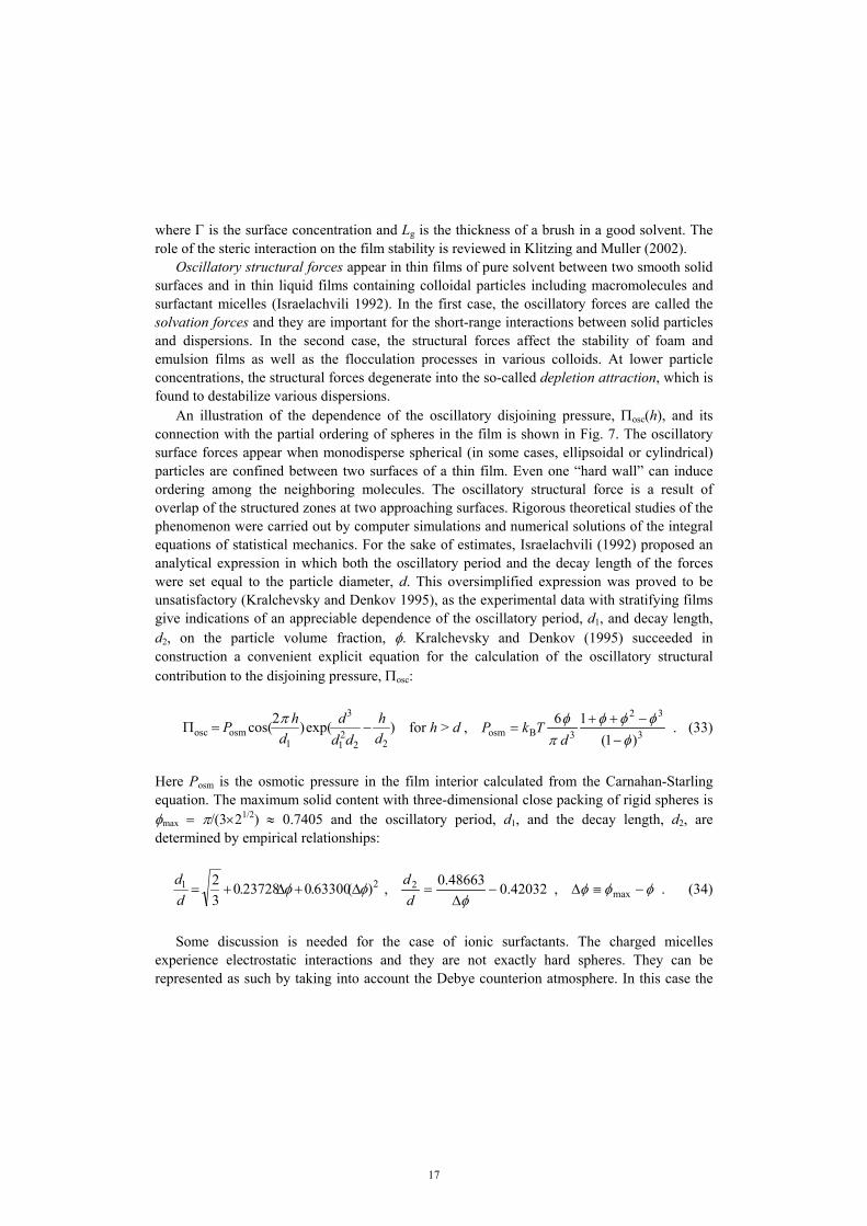
where Γ is the surface concentration and Lg is the thickness of a brush in a good solvent. The role of the steric interaction on the film stability is reviewed in Klitzing and Muller (2002). Oscillatory structural forces appear in thin films of pure solvent between two smooth solid surfaces and in thin liquid films containing colloidal particles including macromolecules and surfactant micelles (Israelachvili 1992). In the first case, the oscillatory forces are called the solvation forces and they are important for the short-range interactions between solid particles and dispersions. In the second case, the structural forces affect the stability of foam and emulsion films as well as the flocculation processes in various colloids. At lower particle concentrations, the structural forces degenerate into the so-called depletion attraction, which is found to destabilize various dispersions. An illustration of the dependence of the oscillatory disjoining pressure, Πosc(h), and its connection with the partial ordering of spheres in the film is shown in Fig. 7. The oscillatory surface forces appear when monodisperse spherical (in some cases, ellipsoidal or cylindrical) particles are confined between two surfaces of a thin film. Even one “hard wall” can induce ordering among the neighboring molecules. The oscillatory structural force is a result of overlap of the structured zones at two approaching surfaces. Rigorous theoretical studies of the phenomenon were carried out by computer simulations and numerical solutions of the integral equations of statistical mechanics. For the sake of estimates, Israelachvili (1992) proposed an analytical expression in which both the oscillatory period and the decay length of the forces were set equal to the particle diameter, d. This oversimplified expression was proved to be unsatisfactory (Kralchevsky and Denkov 1995), as the experimental data with stratifying films give indications of an appreciable dependence of the oscillatory period, d1, and decay length, d2, on the particle volume fraction, φ. Kralchevsky and Denkov (1995) succeeded in construction a convenient explicit equation for the calculation of the oscillatory structural contribution to the disjoining pressure, Πosc:
)exp()2cos(22
21
3
1osmosc d
hdd
dd
hP −=Ππ for h > d , 3
32
3Bosm )1(16
φφφφ
πφ
−−++
=d
TkP . (33)
Here Posm is the osmotic pressure in the film interior calculated from the Carnahan-Starling equation. The maximum solid content with three-dimensional close packing of rigid spheres is φmax = π/(3×21/2) ≈ 0.7405 and the oscillatory period, d1, and the decay length, d2, are determined by empirical relationships:
21 )(63300.023728.032 φφ ∆+∆+=
dd
, 42032.048663.02 −∆
=φd
d , φφφ −≡∆ max . (34)
Some discussion is needed for the case of ionic surfactants. The charged micelles
experience electrostatic interactions and they are not exactly hard spheres. They can be represented as such by taking into account the Debye counterion atmosphere. In this case the
18
effective diameter, deff = dcore + 2κ−1, is identified with d in equations (33) and (34), where dcore denotes the hydrodynamic diameter of the micelles themselves, measured, for instance, by dynamic light scattering (Richetti and Kékicheff 1992, Schmitz 1996). The inverse Debye screening length, κ, is defined by Eq. (27).
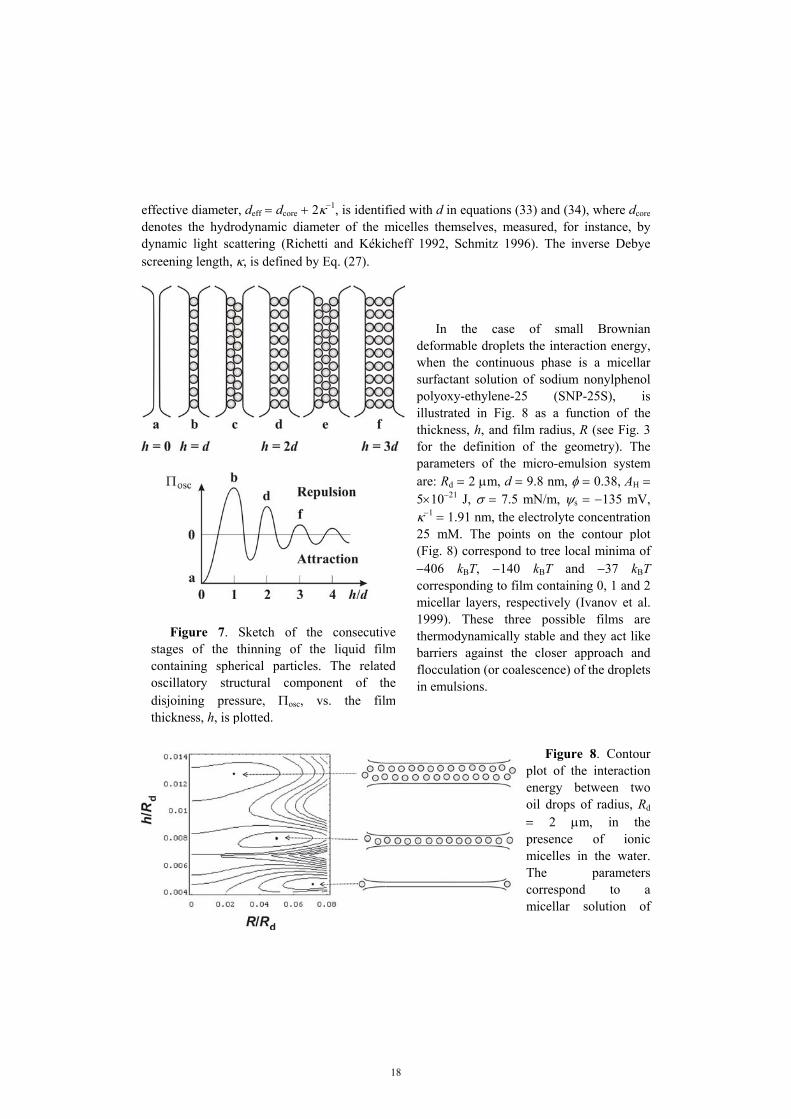
In the case of small Brownian deformable droplets the interaction energy, when the continuous phase is a micellar surfactant solution of sodium nonylphenol polyoxy-ethylene-25 (SNP-25S), is illustrated in Fig. 8 as a function of the thickness, h, and film radius, R (see Fig. 3 for the definition of the geometry). The parameters of the micro-emulsion system are: Rd = 2 µm, d = 9.8 nm, φ = 0.38, AH = 5×10⁻²¹ J, σ = 7.5 mN/m, ψs = −135 mV, κ−1 = 1.91 nm, the electrolyte concentration 25 mM. The points on the contour plot (Fig. 8) correspond to tree local minima of −406 kBT, −140 kBT and −37 kBT corresponding to film containing 0, 1 and 2 micellar layers, respectively (Ivanov et al. 1999). These three possible films are thermodynamically stable and they act like barriers against the closer approach and flocculation (or coalescence) of the droplets in emulsions.
Figure 8. Contour plot of the interaction energy between two oil drops of radius, Rd = 2 µm, in the presence of ionic micelles in the water. The parameters correspond to a micellar solution of
Figure 7. Sketch of the consecutivestages of the thinning of the liquid filmcontaining spherical particles. The relatedoscillatory structural component of thedisjoining pressure, Πosc, vs. the filmthickness, h, is plotted.

19
sodium nonylphenol polyoxy-ethylene-25 (SNP-25S). The points on the plot correspond to three local minima of 0, 1 and 2 micellar layers, respectively. The accumulated experimental and theoretical results imply that there are at least two kind of hydrophobic surface forces of non-electrostatic physical origin. The first one is due to gaseous capillary bridges (cavitation) between the hydrophobic surfaces (Yushchenko et al. 1983, Pashley et al. 1985, Christenson and Claesson 1988). The formation of gaseous capillary bridges leads to jumps in the experimental force-distance dependence and, moreover, the strength of the interaction increases with the concentration of gas dissolved in water. The second is due to hydrogen-bond-propagated ordering of water molecules in the vicinity of such surfaces (Eriksson et al. 1989, Israelachvili 1992, Paunov et al. 2001). A review was recently published by Christenson and Claesson (2001). In this case the attraction is monotonic and decays exponentially at long distances, with a decay length about 15.8 nm. In principle, the two kinds of hydrophobic surface forces could act simultaneously, and it is not easy to differentiate their effects. If we have a hydrophobic interface, rather than a separate hydrocarbon chain, the ordering of the subsurface water molecules will propagate into the bulk of the aqueous phase. Such ordering is entropically unfavorable. When two hydrophobic surfaces approach each other, the entropically unfavored water is ejected into the bulk, thereby reducing the total free energy of the system. The resulting attraction can in principle explain the hydrophobic surface force of the second kind. For the hydrophobic part of the disjoining pressure, Πhb, Eriksson et al. (1989) derived the following expression:
)2/(sinh1
4)( 2hb
λλπ hBh −=Π . (35)
The parameters B and λ characterize, respectively, the strength of the hydrophobic interaction and its decay length. According to Eriksson et al. (1989), B should increase with the degree of hydrophobicity of the surfaces, whereas the decaylength λ should be the same for all hydrophobic surfaces under identical solution conditions. Equation (35) was successfully applied by Paunov et al. (2001) to interpret emulsification data. Many effects can contribute to the energy of interaction between two fluid particles and the total disjoining pressure, Π, becomes a superposition of all of them, Π = ΠVW + Πel + Πst + Πosc + Πhb + … (for other contributions in Π see Kralchevsky et al. 2002). For each specified system an estimate may reveal, which of the contributions in the disjoining pressure are predominant, and which of them can be neglected. The analysis shows that the same approach can be applied to describe the multi-droplet interactions in flocs, because in most cases the interaction energy is pair-wise additive. 5 Hydrodynamic interactions in thin liquid films It is now generally recognized that the presence of surfactants plays an important role for the drainage velocity of thin liquid films and the hydrodynamic forces in these films. The

20
surfactants change not only the disjoining pressure, but also the tangential mobility of the interface of the droplet or bubble. This affects the flocculation and coalescence rate constants, which determine the rates of reversible and irreversible coagulation of the dispersions and emulsions. When two colloidal particles come close to each other, they experience hydrodynamic forces, which originate from the interplay of the hydrodynamic flows around two moving colloidal particles or two film surfaces. It becomes important when the separation between the particle surfaces is of the order of the particle radius and increases rapidly with the decrease of the gap width. The simultaneous action of disjoining pressure and hydrodynamic forces determines the stages of the formation and evolution of a liquid film of fluid surfaces (Ivanov et al. 1975, Ivanov and Dimitrov 1988).
Figure 9. Consecutive stages of evolution of a thin liquid film between two bubbles or drops: a) mutual approach of slightly deformed surfaces; b) the curvature at the film center inverts its sign and a "dimple" arises; c) the dimple disappears and an almost plane-parallel film forms; d) due to thermal fluctuations or other disturbances the film either ruptures or transforms into a thinner Newton black film; e) Newton black film expands; f) the final equilibrium state of the Newton black film is reached. At large distances the fluid particles approach each other and the hydrodynamic interaction is so small that they are slightly deformed (see Fig. 9a). A dimple is formed at a certain small separation between the fluid particles – the dimple initially grows, but latter becomes unstable and quickly outflows (see Fig. 9b). At a given thickness (called the inversion thickness, hit) a plane-parallel film of radius R and typical thickness from 15 to 200 nm forms (see Fig. 9c). When the long-range repulsive forces are strong enough an equilibrium (but thermodynamically metastable) primary film (called the common black film) can form. The film surface corrugations, caused by thermal fluctuations or other disturbances and amplified by attractive disjoining pressure, may increase their amplitude so much that the film either ruptures or a spot of thinner Newton black film (NBF) forms (see Fig. 9d). If the short-range

21
repulsive disjoining pressure is large enough the black spots (secondary films of very low thickness, h2 ≈ 5÷10 nm, and a radius Rsp) are stable. They either coalescence or grow in diameter, forming an equilibrium secondary (NBF) thin film (see Fig. 9e). After the whole film area is occupied by the Newton black film, the equilibrium between the film and the meniscus is violated and the NBF expands until reaching its final equilibrium radius, RNBF, corresponding to an equilibrium contact angle θ (see Fig. 9f).
The time limiting factor for the approach of two fluid particles determines from the process of mutual approach at large distances (see Fig. 9a) and from the drainage time of the plane-parallel film between deformed interfaces (see Fig. 9c). The solution of the problem about the hydrodynamic interaction between two rigid spherical particles, approaching each other across a viscous fluid, was obtained by Taylor. In fact, this solution does not appear in any G.I. Taylor’s publications but in the article by Hardy and Bircumshaw (1925) it was published (see Horn et al. 2000). Two spherical emulsion drops of tangentially immobile surfaces are hydrodynamically equivalent to the two rigid particles considered by Taylor. The hydrodynamic interaction is due to the viscous dissipation of energy when the liquid is expelled from the gap between the spheres. The geometry of the system is illustrated in Fig. 10. The friction force decreases the approaching velocity of spherical particles, VTa, proportionally to the decrease of the surface-to-surface distance h in accordance with the equation:
)(3
2s2
dTa FF
RhV −=ηπ
, ∫∞
Π≡0
s d2 rrF π , d2d1
d2d1d
2RRRR
R+
≡ , (36)
where F is the external force exerted on each drop, Fs is the surface force originating from the intermolecular interactions between the two drops across the liquid medium and Rd is the mean radius of the droplets. Equation (36) is derived using the lubrication approximation and the disjoining pressure approach described in Sec. 3.
When surfactant is present in the continuous phase at not too high concentration, then the surfactant adsorption monolayers, covering the emulsion drops, are tangentially mobile, rather than immobile. The adsorbed surfactant can be dragged along by the fluid flow in the gap between two colliding drops thus affecting the hydrodynamic interaction between them. The appearance of gradients of surfactant adsorption is opposed by the Gibbs elasticity, surface viscosity, surface and bulk diffusion. If the driving
Figure 10. Sketch of two approaching dropletsof radii Rd1 and Rd2 at a distance h. Possible dimpleand pimple formations are illustrated.

22
force F (say the Brownian or the buoyancy force) is small compared to the capillary pressure of the droplets, the deformation of two spherical droplets upon collision will be only a small perturbation in the zone of contact. Then the film thickness and the pressure within the gap can be presented as a sum of a non-perturbed part and a small perturbation. Solving the resulting hydrodynamic problem for negligible interfacial viscosity, an analytical formula for the velocity of drop approaching, V = −dh/dt, is derived for nonionic surfactants (Ivanov and Dimitrov 1988):
1s
Ta]1)ln([
2−−
++=
hhd
dhd
hh
VV ,
GED
h ss
6η≡ ,
ch
∂Γ∂
≡a , Ga
3EhDb η
≡ , b
hd
+≡
1s . (37)
Here the parameter b accounts for the effect of bulk diffusion, hs has a dimension of length and takes into account the effect of surface diffusion, EG is the Gibbs elasticity and ha is the adsorption length. In the limiting case of very large Gibbs elasticity EG (tangentially immobile interface) the parameter d tends to zero and then Eq. (37) yields V → VTa. When the distance between droplets, h, decreases the role of the interfacial mobility increases. The hydrodynamic friction in the gap is much higher that that in the droplets and a small amount of surfactant is enough to prevent the mobility of film interfaces. In the case without surfactants the energy dissipates also in the drop phases and the viscosity of the disperse phase, ηd, becomes important. A number of solutions, generalizing the Taylor equation (36), have been obtained. In particular, the velocity of central approach of two spherical drops in pure liquid, V, is related to the Taylor velocity, VTa, through the following expression
ξξξ
402.01461.0711.11 2
Ta +++
=VV , h
R2
dd
ηη
ξ ≡ (38)
derived by Davis et al. (1989) by means of a Padé-type approximation. Note that in the case of close approach of two drops, h → 0, the velocity V is proportional to h1/2 and the two drops can come into contact in a finite period of time. The role of surface viscosity, type of the disperse phase and surfactants are widely studied in the literature (Cristini et al. 1998, Valkovska et al. 1999, Chesters and Bazhlekov 2000, Danov et al. 2001, etc.). Experimental data (Dickinson et al. 1988) shows that the emulsion stability correlates well with the lifetime of separate thin emulsion films or of drops coalescing with their homophase. The lifetime of oil drops pressed against their homophase by the buoyancy force measured by Dickinson et al. (1988) is plotted in Fig. 11. In the experiments the droplets were so small that the plain-parallel films were not form. To define the lifetime, τ, the film thickness at initial moment, hin, and at the final moment, hfin, are assumed to be known and

23
∫=in
fin
d1h
h
hV
τ . (39)
For the calculation of the velocity, V, in Eq. (39) equations (36) and (37) are used. It is well illustrated that the lifetime is larger for the smaller droplets. The lifetime for slightly deformed droplets decreases with the increase of the driving force, F, and the drop radius, Rd. Note, that for large drops when a plane-parallel film is formed the dependence, τ vs. Rd, is exactly the opposite (see below). The formation of a dimple (see Fig. 9b) is observed when there is no significant attractive disjoining pressure and the capillary pressure is not large enough to counteract the normal viscous stress and the positive component of the disjoining pressure. Then it may happen that at a given gap width (called inversion thickness, hit, Ivanov et al. 1975 and Ivanov and Dimitrov 1988), the droplets deform considerably and their caps becomes flat. Since the flat surface cannot sustain the viscous stress, the
interfacial shape in the gap changes suddenly from convex to concave, i.e. a dimple forms. If the disjoining pressure, Π, is negative, the two film surfaces will attract each other, i.e. the disjoining pressure will counteract the hydrodynamic pressure thus decreasing the deformation. Because of the different dependence of these pressures on the thickness, h, (see Sec. 4 where it is shown that Π depends very strong on h), it may happen that at a given thickness, hpt, the disjoining pressure effect totally eliminates the viscous deformation of the caps of the droplets (Fig. 10). At this moment the sum of the dynamic pressure and the disjoining pressure becomes zero. At smaller thickness it will become negative and then protrusions will form at the drop caps. Because of its shape (this protrusions are opposite to the dimple) hpt is called pimple thickness. In the case of nonionic surfactants and negligible surface viscosity effect hit and hpt become solutions of the following equations (Valkovska et al. 1999 and Danov et al. 2001):
1)(2
)(2 it
dit
it
s =Π+−
hR
hGhFF
σσπ , 0)()( ptpt
ptd
s =Π+−
hhGhRFF
π , (40)
Figure 11. Experimental data ofDickinson et al. (1988) for the lifetime ofsmall drops vs. their radius, Rd.

24
where the dimensionless mobility function G(h) is defined as
hdhdhdhdhdhG
/)/1ln()/1()/1ln(/)(−++
+−≡ . (41)
In the case of tangentially immobile interfaces (in Eq. 41 G → 1 when d/h → 0, which corresponds to the limit of a large Gibbs elasticity) and negligible effect of the disjoining pressure one can estimate from Eq. (40) that the inversion thickness obeys the simple expression hit = F/(2πσ). For mobile surfaces hit decreases. In contrast the pimple thickness does not depend on the interfacial tension and for tangentially immobile surfaces and van der Waals disjoining pressure (see Eq. 23) hpt = [AHRd/(12F)]1/2.
The above conclusions are illustrated in Fig. 12. The experimental data for a system of two approaching small droplets of soybean oil in water are used as physical parameters. The aqueous film is stabilized by bovine serum albumin (BSA) with 0.15 M sodium chloride to suppress the electrostatic interactions. The density difference is 0.072×10³ kg/m3, and the experimentally determined interfacial tension was 7, 15 and 30 mN/m for different concentrations of BSA. In the expression for the van der Waals attraction at small and large distances the Hamaker constant
was calculated from Eq. (25). One sees (Fig. 12) that the larger the drop radius the earlier the film forms. The inversion thickness reaches 500 nm for drop radii of 200 µm. The equation (40) for hit has no solution for drop radii smaller than 80 µm. The pimple thickness decreases with the increase of the drop radius, i.e. with the larger driving force. Drops below 80 µm will coalescence or will form a very thin film (NBF) if the steric interaction takes place. The formation of pimple has been found out by Yanitsios and Davis (1991) in computer calculations for emulsion drops from pure liquids, without any surfactant. Next, by means of numerical calculations Cristini et al. (1998) established the formation of pimple for emulsion drops covered with insoluble surfactant in the case of negligible surface diffusion; their computations showed that a rapid coalescence took part for h < hpt. A complete treatment of the problem for the formation of pimple was given by Valkovska et al. (1999), where the effects of surface and bulk diffusion of surfactant, as well as the surface elasticity and viscosity, were taken into account.
Figure 12. Effect of the drop radius, Rd, on theinversion, hit, and pimple thickness, hpt.

25
In the case when h < hit a liquid film is formed in the zone of contact of two emulsion drops (see Fig. 3 and Fig. 9c). Such configuration appears between drops in flocs and in concentrated emulsions, including creams. In a first approximation, one can assume that the viscous dissipation of energy happens mostly in the thin liquid film intervening between two drops. Some energy dissipates also in the Plateau border. If the interfaces are tangentially immobile (owing to adsorbed surfactant) then the velocity of approach of the two drops can be estimated by means of the Reynolds formula for the velocity of approach of two parallel solid discs of radius R, equal to the film radius (Reynolds 1886): VRe = 2h3(F − Fs)/(3πηR4). The Reynolds velocity is used as a scaling factor of the drainage velocity of deformed drops. When the surfactant is soluble only in the continuous phase the respective rate of film thinning V is affected by the surface mobility mainly by through the Gibbs elasticity EG, just as it is for foam films (Radoev et al. 1974, Traykov et al. 1977 and 1977a, Ivanov 1980, Ivanov and Dimitrov 1988, Danov et al. 1999a). The solution of the lubrication approximation problem for the drainage velocity in the case of nonionic surfactants for the geometry given in Fig. 3 reads (Danov et al. 1999a):
)}1ln(]1)1([1{2
/11
d
2
d
2
s4
32d
s
Re
hd
hRR
dh
hRR
hRhR
hhbVV
++−+−+++
= . (42)
The interfacial parameters b, hs and d are defined with Eq. (37). Note that the bulk and surface diffusion fluxes, which tend to damp the surface tension gradients and to restore the uniformity of the adsorption monolayers, accelerate the film thinning, see Eqs. (37) and (42). Moreover, since Ds in Eq. (37) is divided by the film thickness h, the effect of surface diffusion dominates that of bulk diffusion for small values of the film thickness. On the other hand, the Gibbs elasticity EG (the Marangoni effect) decelerates the thinning. Equation (42) predicts that the circulation of liquid in the droplets does not affect the rate of thinning. The role of the Plateau border is well illustrated in Eq. (42). For instance, if the Gibbs elasticity is large enough to prevent the mobility of the film interfaces equation (42) is simplified to:
TaReTaRe
1111VVVVV
++= . (43)
For R → 0 (non-deformed spherical drops) equation (43) reduces to V = VTa. On the contrary, for h → 0 one has 1/VTa << 1/VRe, and then Eq. (43) yields V → VRe. Direct measurements of the lifetime of the drops pressed by buoyancy against a large interface in both Taylor and Reynolds regimes are reported in Basheva et al. (1999) and Gurkov and Basheva (2002) for a wide range of systems. In Fig. 13 the experimental data and the theoretical curve calculated from Eqs. (39) and (43) are presented. The system consists of soybean oil and aqueous solution of 4×10⁻⁴ wt% BSA + 0.15 M NaCl. The films were detected for droplets above 120 µm in size. Small (micrometer size) droplets are unstable when their
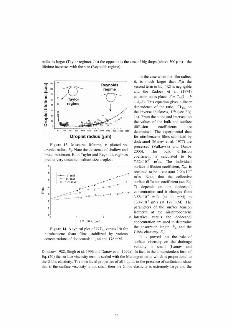
26
radius is larger (Taylor regime). Just the opposite is the case of big drops (above 300 µm) – the lifetime increases with the size (Reynolds regime).
In the case when the film radius, R, is much larger than Rdh the second term in Eq. (42) is negligible and the Radoev et al. (1974) equation takes place: V = VRe(1 + b + hs/h). This equation gives a linear dependence of the ratio, V/VRe, on the inverse thickness, 1/h (see Fig. 14). From the slope and intersection the values of the bulk and surface diffusion coefficients are determined. The experimental data for nitrobenzene films stabilized by dodecanol (Manev et al. 1977) are processed (Valkovska and Danov 2000). The bulk diffusion coefficient is calculated to be 7.32×10⁻¹⁰ m2/s. The individual surface diffusion coefficient, Ds0, is obtained to be a constant 2.90×10⁻⁹ m2/s. Note, that the collective surface diffusion coefficient (see Eq. 7) depends on the dodecanol concentration and it changes from 3.55×10⁻⁹ m2/s (at 11 mM) to 13.4×10⁻⁹ m2/s (at 178 mM). The parameters of the surface tension isotherm at the air/nitrobenzene interface versus the dodecanol concentration are used to determine the adsorption length, ha, and the Gibbs elasticity, EG. It is proved that the role of surface viscosity on the drainage velocity is small (Ivanov and
Dimitrov 1988, Singh et al. 1996 and Danov et al. 1999a). In fact, in the dimensionless form of Eq. (20) the surface viscosity term is scaled with the Marangoni term, which is proportional to the Gibbs elasticity. The interfacial properties of all liquids in the presence of surfactants show that if the surface viscosity is not small then the Gibbs elasticity is extremely large and the
Figure 13. Measured lifetime, τ, plotted vs.droplet radius, Rd. Note the existence of shallow andbroad minimum. Both Taylor and Reynolds regimespredict very unstable medium-size droplets.
Figure 14. A typical plot of V/VRe versus 1/h fornitrobenzene foam films stabilized by variousconcentrations of dodecanol: 11, 44 and 178 mM.

27
interfaces become immobile. Therefore, the surface viscosity term can be neglected when the drainage velocity is studied – this term can be important for investigation of the stability of the liquid films. In the opposite case, when the surfactants are soluble only in the disperse phase, the process of convective bulk diffusion is so fast that the liquids behave as pure liquids (Traykov et al. 1977 and 1977a, Ivanov 1980, Ivanov and Dimitrov 1988, Danov et al. 2001). The surfactants remain uniformly distributed throughout the drop surface during the film thinning and interfacial tension gradients do not appear. For that reason, the drainage of the film surfaces is not opposed by surface tension gradients and the rate of film thinning, V, is the same as in the case of pure liquid phases. For an intensive drainage of films with large radii, R, the velocity, V, is calculate from the approximate expression (Ivanov and Dimitrov 1988):
3/1
s4
43dd
eRe]
)(108
[1FFh
RhV
V−
≈≈≈ηρ
ηπηδη
ε , (44)
where εe is called emulsion parameter, δ is the thickness of the hydrodynamic boundary layer inside the drops, ρ is the mass density of the continuous phase and ηd is the dynamic shear viscosity of the disperse phase. The validity of Eq. (44) was confirmed experimentally (Traykov et al. 1977a, Ivanov 1980, Ivanov and Dimitrov 1988). In the beginning stages of mixing in the processes of emulsification large masses of the dispersed phase are embedded in a continuous phase – the large masses of fluids are stretched and folded over. At this stage the capillary number, which is the ration of the viscous forces to the interfacial forces, is very large and the interfacial forces do not play a significant role. As the process evolves, the capillary number decreases and the extended blobs break into many smaller drops. Concurrently, smaller drops begin to collide with each other and may coalescence into larger drops, which may in turn break again. The breakup and coalescence processes complete against each other and it is the result of this competition, which determines the final drop size distribution or morphology. In this case the both phases behave as pure liquids and the drainage velocity of two approaching drops depends considerably from the viscosity of the dispersed and continuous phases and the distance between drops. It leads to a complex hydrodynamic problem, which can be solved only numerically. A list of some approximations is given in Fig. 15 (Chesters 1991 and de Roussel et al. 2001). It is well illustrated that the viscous dissipation of energy in the drops can be important for pure liquids. De Roussel et al. (2001) confirmed experimentally this fact and investigated the mixing of viscous immiscible liquids. If the thickness of a free liquid film gradually decreases owing to the drainage of liquid, the film typically breaks when it reaches a sufficiently small thickness, called the critical thickness, unless some repulsive surface forces are able to provide stabilization (see Fig. 9d – 9f). The mechanism of breakage (in the absence of repulsive forces) was proposed by de Vries (1958) and developed in subsequent studies (Scheludko 1962, Vrij 1966, Ivanov et al. 1974, Ivanov and Dimitrov 1974, Ivanov 1980). According to this mechanism, the film rupture

28
results from the growth of capillary waves at the film surfaces (see Fig. 9d) promoted by attractive surface forces (say, the van der Waals forces), which are operative in the film.
Drainage rate Criteria
Rigid drop, ηd >> η
2d
s
3)(2
RFFh
Vηπ−
≈ σπ2
sFFh
−>
Immobile interfaces, ηd >> η
)(38
s2d
32
FFRhV−
≈η
σπ ηη
σπd2/1ds ]
2)(
[3<
− RFFh
Partially mobile interfaces, O(η) ≈ O(ηd)
2/1sd
22/3d
)()/2(2
FFhR
V−
≈ηπσπ
2/1dsd2/1
ds]
2)(
[3])(
2[6σπη
ησπ RFFhRFF
h−
<<−
Fully mobile interfaces, ηd << η
d32
RhVησ
≈ 2/1
ds
d ])(
2[6RFF
h−
<σπ
ηη
Figure 15. Rate of drainage of the continuous film between two drops (pure liquids) is determined by the rigidity and mobility of the drops. In fact, thermally excited fluctuation capillary waves are always present on the film surfaces. With the decrease of the average film thickness, h, the attractive surface force

29
enhances the amplitude of some modes of the fluctuation waves. At the critical thickness, hcr, the two film surfaces locally touch each other due to the surface corrugations, and then the film breaks. A recent version of this capillary-wave model (Danov et al. 2001 and Valkovska et al. 2002), which takes into account all essential physicochemical and hydrodynamic factors, show an excellent agreement with the experiments for the critical thickness of foam and emulsion films (Manev et al. 1984).
For experimental observation of the drainage and stability of liquid films the capillary cell illustrated in Fig. 16 is widely used (Scheludko and Exerowa 1959). First, the cylindrical glass cell is filled with the working liquid (say, water solution); next, a portion of the liquid is sucked out from the cell through the orifice in the glass wall. Thus, in the central part of the cell a liquid film is formed, which is encircled by a Plateau border. By adjustment of the capillary pressure the film radius, R, is controlled. The arrow (see Fig. 16) denotes the direction of illumination and microscope observation. The optical microscopic observations and the
measurements of h are carried out in reflected monochromatic light of wavelength λ0 = 551 nm. In particular, h, is determined from the registered intensity, I, of the light reflected from the film, by means of the formula
])1/()1(41
arcsin[2 2
0
QQnh
−∆−+
∆=
πλ
, (45)
where ∆ = (I − Imin)/(Imax − Imin), h is calculated assuming a homogeneous refractive index equal to the bulk solution value; Q = (n − 1)2/(n + 1)2; I is the instantaneous value of the reflected intensity, while Imax and Imin refer to the last interference maximum and minimum values. The intensity, I, is registered by means of a photo-multiplier, whose electric signal is recorded as a function of time. Typical photos of thinning films are illustrated in Fig. 17. The investigated films behaved in the following way. After the initial dynamic stages of film thinning (see Fig. 9a and 9b), almost plane-parallel films formed (see Fig. 9c), whose thickness was gradually decreasing. At 0.3 M NaCl the film looks dark gray in reflected light just before it ruptures (see Fig. 9d). At 0.1 M NaCl formation of black spots, corresponding to a secondary film, is seen (Fig. 9e). In both photos the film is encircled by Newton interference rings located in the Plateau border.
Figure 16. Sketch of the experimentalcapillary cell.

30
a) b) Figure 17. Photos of thinning films of radius R = 155 µm formed from solutions of 10 µM SDS and background electrolyte: a) 0.3 M NaCl; b) 0.1 M NaCl.
To describe mathematically the process of thin liquid film instability the shape of the corrugated film surfaces is presented as a superposition of Fourier-Bessel modes, proportional to J0(kr/R), for all possible values of the dimensionless wave number k (J0 is the zeroth order Bessel function). The mode, which has the greatest amplitude at the moment of film breakage, and which causes the breakage itself, is called the critical mode, and its wave number is denoted by kcr. The stability-instability transition for this critical mode happens at an earlier stage of the film evolution, when the film thickness is equal to htr − the so-called transitional thickness, htr > hcr (Ivanov 1980). The theory provides a
system of three equations for determining the three unknown parameters: hcr, kcr and htr. According to Valkovska et al. 2002, where the most complete theoretical description of the
Figure 18. Plot of the critical thickness, hcr, vs.the film radius, R, at 0.3 M fixed concentration ofNaCl, for three SDS concentrations, denoted in thefigure.

31
process of simultaneous film drainage and perturbation growth is given, the equations for determining kcr and htr are:
∫∫ Π−Π′
=Π−
tr
cr
tr
crdd
c
3
c
6
3cr
2
2cr h
h
h
hh
Phh
Ph
hRk σ , 3
cr2
2cr
3tr
trc4tr
3cr
tr 2)]([24)(
dd
hRkhhP
hhh
hσ
+Π−=Π . (46)
The critical thickness, hcr, becomes a solution of the following equation:
])(d32
exp[)( tr
cr c
3
3cr
2cr
tr4/1
B
2tr
cr ∫ ΠΠ−
−=h
hh
Ph
hkh
Tkhh σ . (47)
Note, that the problem (46) and (47) describes the case of tangentially immobile interfaces. One proves that the mobility of interfaces changes only slightly the values of hcr – it affects the value of the critical wave number, kcr. The data points in Fig. 18 are processed using equations (46) and (47). The disjoining pressure is presented as a sum of the van der Waals attraction due to Eqs. (22) and (25) and the hydrophobic attraction described by Eq. (35). All parameters for the calculation of ΠVW are known. The only adjustable parameters are B and λ, which characterize the hydrophobic interaction, Eq. (35). As B characterizes the interfacial hydrophobicity, while λ is a bulk property related to the propagating hydrogen-bonding of water molecules, from the fit of the data three different values of B (denoted by B1, B2 and B3) for the three experimental SDS concentrations, and a single value of λ, the same for the whole set of data are obtained. Note, that the used SDS concentrations are extremely small and they cannot affect the hydrogen bonding in the bulk (and the value of λ), while the adsorption of SDS is material and can affect the interfacial hydrophobicity (and the value of B). The results are: B1 = 6.56 × 10⁻⁴ (for 0.5 µM SDS + 0.3 M NaCl); B2 = 4.71 × 10⁻⁴ (for 1.0 µM SDS + 0.3 M NaCl); B3 = 3.34 × 10⁻⁵ (for 10 µM SDS + 0.3 M NaCl) and λ = 15.85 nm. The determined decay length of the hydrophobic force in foam films, λ = 15.85 nm, practically coincides with the value λ = 15.8 obtained in Eriksson et al. (1989) for mica covered with hydrocarbon monolayer (DDOA = dimethyl-dioctadecyl-ammonium bromide) and with monolayer from fluorinated cationic surfactant. The lower two curves in Fig. 18, are calculated substituting B = 0, which means that the hydrophobic surface force is set zero (Πhb = 0). In this case, all parameters of the theory are known, and the theoretical curves are drawn without using any adjustable parameters. The respective computed curve for 1 µM SDS practically coincides with that for 0.5 µM SDS in Fig. 18. The curves calculated for Πhb = 0 lay far away from the experimental points for 0.5 and 1 µM SDS – this fact can be interpreted as a consequence of the action of the hydrophobic force in the film. Note also that hcr(10 µM SDS) > hcr(1 µM SDS) for the curves calculated assuming Πhb = 0, whereas exactly the opposite tendency holds for the respective experimental points.
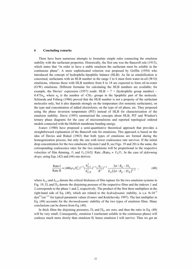
32
6 Concluding remarks There have been numerous attempts to formulate simple rules connecting the emulsion stability with the surfactant properties. Historically, the first one was the Bancroft rule (1913), which states that “in order to have a stable emulsion the surfactant must be soluble in the continuous phase”. A more sophisticated criterion was proposed by Griffin (1954) who introduced the concept of hydrophilic-lipophilic balance (HLB). As far as emulsification is concerned, surfactants with an HLB number in the range 3 to 6 must form water-in-oil (W/O) emulsions, whereas those with HLB numbers from 8 to 18 are expected to form oil-in-water (O/W) emulsions. Different formulae for calculating the HLB numbers are available; for example, the Davies’ expression (1957) reads: HLB = 7 + (hydrophilic group number) − 0.475ng, where ng is the number of -CH2- groups in the lipophilic part of the molecule. Schinoda and Friberg (1986) proved that the HLB number is not a property of the surfactant molecules only, but it also depends strongly on the temperature (for nonionic surfactants), on the type and concentration of added electrolytes, on the type of oil phase, etc. They proposed using the phase inversion temperature (PIT) instead of HLB for characterization of the emulsion stability. Davis (1993) summarized the concepts about HLB, PIT and Windsor's ternary phase diagrams for the case of microemulsions and reported topological ordered models connected with the Helfrich membrane bending energy. Ivanov (1980) have proposed a semi-quantitative theoretical approach that provides a straightforward explanation of the Bancroft rule for emulsions. This approach is based on the idea of Davies and Rideal (1963) that both types of emulsions are formed during the homogenization process, but only the one with lower coalescence rate survives. If the initial drop concentration for the two emulsions (System I and II, see Figs. 19 and 20) is the same, the corresponding coalescence rates for the two emulsions will be proportional to the respective velocities of film thinning, VI and VII [163]: Rate I/RateII ≈ VII/VI. In the case of deforming drops, using Eqs. (42) and (44) one derives:
( ) 3/2IId
Id3/1223/1
2II,cr
3I,cr3/13
12/2/2
)()()486(II RateI Rate
Π−
Π−≈
RER
Rh
hD
Gs
σση
ρ , (48)
where hcr,I and hcr,II denote the critical thickness of film rupture for the two emulsion systems in Fig. 19, ΠI and ΠII denote the disjoining pressure of the respective films and the indexes 1 and 2 corresponds to the phase 1 and 2, respectively. The product of the first three multipliers in the right-hand side of Eq. (48), which are related to the hydrodynamic stability, is c.a. 8×10⁻⁵ dyn2/3cm−1/3 for typical parameter values (Ivanov and Kralchevsky 1997). The last multiplier in Eq. (48) accounts for the thermodynamic stability of the two types of emulsion films. Many conclusions can be drawn from Eq. (48). In thick films the disjoining pressures, ΠI and ΠII, are zero, and then the ratio in Eq. (48) will be very small. Consequently, emulsion I (surfactant soluble in the continuous phase) will coalesce much more slowly than emulsion II; hence emulsion I will survive. Thus we get an

33
explanation of the empirical Bancroft rule. The emulsion behavior in this case is controlled mostly by the hydrodynamic factors, i.e. the factors related to the kinetic stability.
The Gibbs elasticity, EG, favors the formation of emulsion I, because it slows down the film thinning. On the other hand, increased surface diffusivity, D1s, decreases this effect, because it helps the interfacial tension gradients to relax thus facilitating the formation of emulsion II. The film radius, R, increases, whereas the capillary pressure, 2σ/Rd, decreases with the rise of the drop radius. Therefore, larger drops will tend to form emulsion I, although the effect is not very pronounced, see Eq. (48). The difference between the critical thicknesses of the two emulsions affects only slightly the rate ratio. The viscosity of the surfactant-
containing phase, η1, does not appear in Eq. (48) and there is only a weak dependence on η2. This fact is consonant with the experimental findings about a negligible effect of viscosity (Davies and Rideal 1963, p. 381). The interfacial tension, σ, affects directly the rate ratio through the capillary pressure. The addition of electrolyte would affect mostly the electrostatic component of the disjoining pressure, see Eq. (26), which is suppressed by the electrolyte – the latter has a destabilizing effect on O/W emulsions. Surface-active additives (such as cosurfactants, demulsifiers, etc.) may affect the emulsifier partitioning between the phases and its adsorption, thereby changing the Gibbs elasticity and the interfacial tension. The surface-active additive may change also the surface charge (mainly through increasing the spacing among the emulsifier ionic headgroups) thus decreasing the electrostatic disjoining pressure and favoring the W/O emulsion. Polymeric surfactants and adsorbed proteins increase the steric repulsion between the film surfaces; they may favor either of the emulsions O/W or W/O depending on their conformation at the interface and their surface activity (Danov et al. 2001, Kralchevsky et al. 2002). The temperature affects strongly both the solubility and the surface activity of non-ionic surfactants (Adamson and Gast 1997). It is well known that at higher temperature non-ionic surfactants become more oil-soluble, which favors the W/O emulsion. These effects may change the type of emulsion formed at the phase inversion temperature (PIT). The temperature effect has numerous implications, some of them being the change of the Gibbs elasticity, EG, and the interfacial tension, σ.
Figure 19. Two possible types of emulsionsobtained just after homogenization for deformeddrops: the surfactants are soluble in phase 1.

34
The disjoining pressure, Π, can substantially change, and even reverse, the behavior of the system if it is comparable by magnitude with the capillary pressure, 2σ/Rd. For instance, if (2σ/Rd − ΠII) → 0 at finite value of (2σ/Rd − ΠI), then the ratio in Eq. (48) may become much larger than unity, which means that System II will become thermodynamically stable. This fact can explain some exclusion from the Bancroft rule, like that established by Binks (1993 and 1998).
Equation (48) is derived for deforming emulsion drops, which can approach each other at a surface-to-surface distance smaller than the inversion thickness, hit, see Eq. (40). Other possibility is the case of micro-emulsions when the drops remain spherical during their collision, up to their eventual coalescence at h = hcr. In such a case the expressions for the rate ratio is different. Let us first consider the case of System II (surfactant inside the drops, Fig. 20) in which case the two drops approach each other like drops from pure liquid phases (if only the surface viscosity effect is negligible). Therefore, to estimate the velocity of approach of such two
aqueous droplets one can use equation (38). On the other hand, the velocity VI of droplet approach in System I can be expressed by means of Eq. (37). Note that the Taylor velocities for System I and System II are different because of differences in viscosity and droplet-droplet interaction. Then the following criterion for formation of emulsion of type I and II is obtained (Ivanov and Kralchevsky 1997 and Danov et al. 2001):
( )( )IIs
Is12/1
d]1)ln([)(
2233.1
II RateI Rate
FFFF
hhd
dhd
Rh
hhs
−−
−++
≈ − . (49)
For typical emulsion systems one has Rd >> hcr, and equation (49) yields Rate I/Rate II << 1. Therefore, System I (with surfactant in the continuous phase, Fig. 20) will survive. This prediction for spherical drops is analogous to the conclusion for deformable drops. Both these predictions essentially coincide with the Bancroft rule and are valid for cases, in which the hydrodynamic stability factors prevail over the thermodynamic ones. The latter become
Figure 20. Two possible types of mini-emulsions obtained just after homogenization forspherical drops: the surfactant is soluble in phase 1.

35
significant close to the equilibrium state, Fs ≈ F, and could bring about exclusions from the Bancroft rule, especially when (F − Fs)II → 0. The increase of the bulk and surface diffusivities, D1 and D1s, which tend to damp the surface tension gradients, leads to an increase of the parameters b and d (see Eq. 37), which decreases the difference between Rate I and Rate II. In contrast, the increase of the Gibbs elasticity, EG, leads to decrease of d (see Eq. 37) and thus favors the survival of System I. These are the same tendencies as for deforming drops. Equations (48) and (49) lead to some more general conclusions than the original Bancroft rule (e.g. the possibility for inversion of the emulsion stability due to disjoining pressure effects). We neither claim that Bancroft rule, or its extension based on Eqs. (48) and (49), have general validity, nor that we have given a general explanation of the emulsion stability. The coagulation in emulsions is such a complex phenomenon, influenced by too many different factors, that according to us any attempt for formulating a general explanation (or criterion) is hopeless. Our treatment is theoretical and it has limitations inherent to the model used and therefore is valid only under specific conditions. It should not be applied to system where these conditions are not fulfilled. The main assumptions and limitations of the model are: the fluctuation-wave mechanism for coalescence is assumed to be operative; the surfactant transfer onto the surface is under diffusion or electro-diffusion control; parameter b defined by Eq. (37) does not account for the demicellization kinetics; etc. Only small perturbations in the surfactant distribution, which are due to the flow, have been considered; however, under strongly non-equilibrium conditions (like turbulent flows) we could find that new effects come into play, which may significantly alter the trend of the phenomenon. References Adamson, A. W., and Gast, A. P. (1997). Physical Chemistry of Surfaces. New York: Wiley, 6t
edition. Alexander, S. J., Physique 38 (1977) 983. Arya, S.P., Air Pollution Meteorology and Dispersion, Oxford Univ. Press, New York, 1999. Bancroft, W.D., J. Phys. Chem. 17 (1913) 514. Barnes, H.A., J.F. Hutton and K. Walters, An Introduction to Rheology, Elsevier, Amsterdam,
1989. Basheva, E.S., T.D. Gurkov, I.B. Ivanov, G.B. Bantchev, B. Campbell and R.P. Borwankar,
Langmuir 15 (1999) 6764. Batchelor, G.K., An Introduction of Fluid Mechanics, Cambridge Univ. Press, London, 1967. Binks, B.P., Langmuir 9 (1993) 25. Binks, B.P., Modern Aspects of Emulsion Science, Royal Society of Information Services,
Cambridge, 1998. Britter, R.E. and R.F. Griffiths (Editors), Dense Gas Dispersion, Elsevier Scientific Pub. Co.,
Amsterdam, 1982. Chesters, A. and I.B. Bazhlekov, J. Colloid Interface Sci. 230 (2000) 229. Chesters, A., Trans. Inst. Chem. Eng. 69 (1991) 259.
36
Christenson, H.K. and P.M. Claesson, Adv. Colloid Interface Sci. 91 (2001) 391. Christenson, H.K. and P.M. Claesson, Science 239 (1988) 390. Cristini, V., J. Blawzdziewicz and M. Loewenberg, J. Fluid Mech. 366 (1998) 259. Danov, K.D., D.N. Petsev and N.D. Denkov, J. Chem. Phys. 99 (1993) 7179. Danov, K.D., D.S. Valkovska and I.B. Ivanov, J. Colloid Interface Sci. 211 (1999a) 291. Danov, K.D., I.B. Ivanov and P.A. Kralchevsky, Interfacial rheology and emulsion stability, in
“Second World Congress on Emulsion”, Paris, 1997, 2-2-152. Danov, K.D., P.A. Kralchevsky and I.B. Ivanov, in “Encyclopedic Handbook of Emulsion
Technology”, J. Sjöblom (Editor), Marcel Dekker, New York, 2001, Ch. 26. Danov, K.D., P.A. Kralchevsky and I.B. Ivanov, in “Handbook of Detergents. Part. A:
Properties”, G. Broze (Editor), Marcel Dekker, New York, 1999, pp. 303. Davies, J. and E. Rideal, Interfacial Phenomena, Academic Press, New York, 1963. Davies, J.T., Proceedings of the 2nd International Congress on Surface Activity, Vol. 1,
Butterworths, London, 1957, p. 426. Davis, H.T., Factors determining emulsion type: HLB and beyond, in Proc. First World
Congress on Emulsion 19-22 Oct. 1993, Paris, 1993, p. 69. Davis, R.H., J.A. Schonberg and J.M. Rallison, Phys. Fluids A1 (1989) 77. de Gennes, P.G., Adv. Colloid Interface Sci. 27 (1987) 189. de Gennes, P.G., C. R. Acad. Sci. (Paris) 300 (1985) 839. de Roussel, P., D.V. Khakhar and J.M. Ottino, Chem. Eng. Sci. 56 (2001) 5511. de Vries, A., Rec. Trav. Chim. Pays-Bas. 77 (1958) 383; Rubber Chem. Tech. 31 (1958) 1142. Debye, P., Physik 2 (1920) 178. Denkov, N.D., D.N. Petsev and K.D. Danov, Phys. Rev. Lett. 71 (1993) 3226. Derjaguin, B.V., N.V. Churaev and V.M. Muller, Surface Forces, Plenum Press: Consultants
Bureau, New York, 1987. Derjaguin, B.V., Theory of Stability of Colloids and Thin Liquid Films, Plenum, Consultants
Bureau, New York, 1989. Dickinson, E., B.S. Murray and G. Stainsby, J. Chem. Soc. Faraday Trans. 84 (1988) 871. Dukhin, S.S., G. Kretzschmar and R. Miller, Dynamics of Adsorption at Liquid Interfaces,
Elsevier, Amsterdam, 1995. Dzyaloshinskii, I.E., E.M. Lifshitz and L.P. Pitaevskii, Adv. Phys. 10 (1961) 165. Edwards, D.A., H. Brenner and D.T. Wasan, Interfacial Transport Processes and Rheology,
Butterworth-Heinemann, Boston, 1991. Eriksson, J.C., S. Ljunggren, and P.M. Claesson, Chem. Soc. Faraday Trans. 85 (1989) 163. Exerova, D. and P.M. Kruglyakov, Foam and Foam Films: Theory, Experiment, Application,
Elsevier, New York, 1998. Felderhof, B. U., J. Chem. Phys. 49 (1968) 44. Griffin, J., Soc. Cosmet. Chem. 5 (1954) 4. Gurkov, T.D. and E.S. Basheva, Hydrodynamic Behavior and Stability of Approaching
Deformable Drops, in “Encyclopedia of Surface and Colloid Science”, A.T. Hubbard (Editor), Marcel Dekker, New York, 2002.
Hamaker, H.C., Physics 4 (1937) 1058.

37
Happel, J. and H. Brenner, Low Reynolds Number Hydrodynamics with Special Applications to Particulate Media, Prentice-Hall, Englewood Cliffs, New York, 1965.
Hardy, W. and I. Bircumshaw, Proc. R. Soc. London A 108 (1925) 1. Hetsroni, G. (Editor), Handbook of Multiphase Systems, Hemisphere Publ., New York, 1982. Horn, R.G., O.I. Vinogradova, M.E. Mackay and N. Phan-Thien, J. Chem. Phys. 112 (2000)
6424. Hunter, R.J., Introduction to Modern Colloid Science, Oxford Univ. Press, New York, 1993. Israelachvili, J.N., Intermolecular and Surface Forces, Academic Press, London, 1992. Ivanov, I.B. and D.S. Dimitrov, Colloid Polymer Sci. 252 (1974) 982. Ivanov, I.B. and D.S. Dimitrov, in “Thin Liquid Films: Fundamentals and Applications”, I.B.
Ivanov (Editor), Marcel Dekker, New York, 1988, pp. 379. Ivanov, I.B. and P. A. Kralchevsky, Colloids Surf. A 128 (1997) 155. Ivanov, I.B., B. Radoev, E. Manev and A. Scheludko, Trans. Faraday Soc. 66 (1970) 1262. Ivanov, I.B., B.P. Radoev, T.T. Traykov, D.S. Dimitrov, E.D. Manev and C.S. Vassilieff, in
“Proceedings of the International Conference on Colloid Surface Science”, E. Wolfram (Editor), Akademia Kiado, Budapest, 1975, p. 583.
Ivanov, I.B., K.D. Danov and P.A. Kralchevsky, Colloids and Surfaces A 152 (1999) 161. Ivanov, I.B., Pure Appl. Chem. 52 (1980) 1241. Keesom, W.H., Proc. Amst. 15 (1913) 850. Kim, S. and S.J. Karrila, Microhydrodynamics: Principles and Selected Applications,
Butterworth-Heinemann, Boston, 1991. Klitzing, R. and H.J. Müller, Curr. Opinion in Colloid & Surface Sci. 7 (2002) 42. Kralchevsky, P.A. and N.D. Denkov, Chem. Phys. Lett. 240 (1995) 385. Kralchevsky, P.A., K.D. Danov and N.D. Denkov, in “Handbook of Surface and Colloid
Chemistry”, K.S. Birdi (Editor), CRC Press, New York, Second Edition, 2002, Ch. 11. Kralchevsky, P.A., K.D. Danov, G. Broze and A. Mehreteab, Langmuir 15 (1999) 2351. Landau, L.D. and E.M. Lifshitz, Electrodynamics of Continuous Media, Pergamon Press,
Oxford, 1960. Landau, L.D. and E.M. Lifshitz, Fluid Mechanics, Pergamon Press, Oxford, 1984. Langmuir, I., J. Chem. Phys. 6 (1938) 873. Leal, G.L., Laminar Flow and Convective Transport Processes. Scaling Principles and
Asymptotic Analysis, Butterworth-Heinemann, Boston, 1992. Lifshitz, E.M., Soviet Phys. JETP (Engl. Transl.) 2 (1956) 73. London, F., Z. Physics 63 (1930) 245. Maldarelli, Ch. and R. Jain, in “Thin Liquid Films: Fundamentals and Applications”, I.B.
Ivanov (Editor), Marcel Dekker, New York, 1988, pp. 497. Manev, E.D., S. V. Sazdanova, C.S. Vassilieff and I.B Ivanov, Ann. Univ. Sofia Fac. Chem.
71(2) (1976/1977) 5. Manev, E.D., S.V Sazdanova and D.T. Wasan, J. Colloid Interface Sci. 97 (1984) 591. Pashley, R.M., P.M. McGuiggan, B.W. Ninham and D.F. Evans, Science 229 (1985) 1088. Paunov, V.N., S.I. Sandler and E.W. Kaler, Langmuir 17 (2001) 4126.
38
Prud'homme, R.K. and S.A. Khan (Editors), Foams: Theory, Measurements and Applications, Мarcel Dekker, New York, 1996.
Radoev, B.P., D.S. Dimitrov and I.B. Ivanov, Colloid Polym. Sci. 252 (1974) 50. Reynolds, O., Phil. Trans. Roy. Soc. (Lond.) A177 (1886) 157. Richetti, P. and P. Kékicheff, Phys. Rev. Lett. 68 (1992) 1951. Russel, W.B., D.A. Saville and W.R. Schowalter, Colloidal Dispersions, Univ. Press,
Cambridge, 1989. Sche, S. and H.M. Fijnaut, Surface Sci. 76 (1976) 186. Scheludko, A. and D. Exerowa, Kolloid-Z. 165 (1959) 148. Scheludko, A., Proc. K. Akad. Wetensch. B 65 (1962) 87. Schmitz, K.S., Langmuir 12 (1996) 3828. Schramm, L.L. (Editor), Suspensions: Fundamentals and Applications in the Petroleum
Industry, American Chemical Society, Washington, 1996. Shinoda, K. and S. Friberg, Emulsion and Solubilization, Wiley, New York, 1986. Singh, G., G.J. Hirasaki and C.A. Miller, J. Colloid Interface Sci. 184 (1996) 92. Sjoblom, J. (Editor), Emulsions and Emulsion Stability, M. Dekker, New York, 1996. Slattery, J.C., Interfacial Transport Phenomena, Springer-Verlag, New York, 1990. Slattery, J.C., Momentum, Energy, and Mass Transfer in Continua, R.E. Krieger, Huntington,
New York, 1978. Stoyanov, S.D. and N.D. Denkov, Langmuir, 17 (2001) 1150. Tambe, D.E. and M.M. Sharma, J. Colloid Interface Sci., 147 (1991) 137. Tambe, D.E. and M.M. Sharma, J. Colloid Interface Sci., 157 (1993) 244. Tambe, D.E. and M.M. Sharma, J. Colloid Interface Sci., 162 (1994) 1. Traykov, T.T and I.B. Ivanov, Int. J. Multiphase Flow 3 (1977) 471. Traykov, T.T., E.D. Manev and I.B. Ivanov, Int. J. Multiphase Flow 3 (1977a) 485. Valkovska D.S., K.D. Danov and I.B. Ivanov, Adv. Colloid and Interface Sci. 96 (2002) 101. Valkovska, D.S. and K.D. Danov, J. Colloid Interface Sci., 223 (2000) 314. Valkovska, D.S. and K.D. Danov, J. Colloid Interface Sci., 241 (2001) 400. Valkovska, D.S., K.D. Danov and I.B. Ivanov, Colloids and Surfaces A 156 (1999) 547. Verwey, E.J.W. and J.Th.G. Overbeek, Theory and Stability of Lyophobic Colloids, Elsevier,
Amsterdam, 1948. Vrij, A., Disc. Faraday Soc. 42 (1966) 23. Yiantsios S.G. and R.H. Davis, J. Colloid Interface Sci. 144 (1991) 412. Yushchenko, V. S., V.V. Yaminsky and E.D. Shchukin, Colloid Interface Sci. 96 (1983) 307.