effect of randomly distributed infills on seismic base shear for rc buildings with soft ground floor...
DESCRIPTION
The common design practice of RC framed building now-a-days is to keep provision for parking facilities. To do so the whole structural system gets the characteristics of soft story and that’s vulnerable to seismic load. Regular design practice (According to BNBC, 1993) of such RC frame is carried out without considering the structural effect of masonry infill and thus the design becomes really unsafe under lateral load. Now-a-days in Bangladesh an extensive urbanization process is going on and apartment buildings with such unsafe design may face disastrous phenomena under medium strength earthquake.The equivalent static force method (ESFM) we use to find the base shear can’t consider the structural effect of masonry infill and the base shear value is underestimated irrespective of the amount of infill application or not. This study will be confined to analyze the effect of random applied structural infill and observe the variation in base shear value for the uncertain infill location for different parameters. To sort out the actual behavior of masonry infill as structural component of RC frame system a numerical study has been carried out using response spectrum method (RSM). The study was involved to find the base shear modification due to the application of random infill with soft ground floor and to get safe design value for such structurally modified building systemIt’s investigated that random application of infill makes the structure behave differently and the base shear value varies in a certain range for same percentage of infill. It makes the building frame stiffer at some locations and modifies the natural period for the random location of infill at structure in presence of soft floor. The structural sway characteristic also changes tremendously. As a result the base shear value increases than that we find by ESFM and the ground floor sway gets high enough to cause failure of the structure. For design simplicity and safety, a modification factor for such soft floor system is sorted. Thus a suitable modification factor is expected to be suggested for the safe design of MI-RC framed structure against seismic vulnerability.TRANSCRIPT
EFFECT OF RANDOMLY DISTRIBUTED INFILLS ON SEISMIC
BASE SHEAR FOR RC BUILDINGS WITH SOFT GROUND FLOOR
Submitted by
Jahid Hasnain
Submitted to the
DEPARTMENT OF CIVIL ENGINEERING
BANGLADESH UNIVERSITY OF ENGINEERING AND TECHNOLOGY
In partial fulfillment of requirements for the degree of
BACHELOR OF SCIENCE IN CIVIL ENGINEERING
2009

DECLARATION
This is hereby declared that the studies contained in this thesis is the result of
investigation carried out by the author except for the contents where specific
references have been made to the investigation of others.
The whole thesis is done under the supervision of Professor Dr. Khan Mahmud
Amanat (Department of Civil Engineering, BUET) and no part of this thesis has been
submitted concurrently for any degree or other qualification to any other institution.
Signature of author
(Jahid Hasnain)

ACKNOWLEDGEMENT
My profound gratitude to almighty Allah for his unlimited kindness and blessings for
what this effort has been successfully carried out.
I wish to express my deepest thanks to Dr. Khan Mahmud Amanat, Professor,
Department of Civil Engineering, BUET for his encouraging supervision al through
the study. His systematic and invaluable guidance with affectionate persuasion have
helped me greatly during the study.
My special gratitude to my parents, the source of inspiration for all my efforts and
achievements.
ABSTRACT
The common design practice of RC framed building now-a-days is to keep provision
for parking facilities. To do so the whole structural system gets the characteristics of
soft story and that’s vulnerable to seismic load. Regular design practice (According to
BNBC, 1993) of such RC frame is carried out without considering the structural effect
of masonry infill and thus the design becomes really unsafe under lateral load. Now-a-
days in Bangladesh an extensive urbanization process is going on and apartment
buildings with such unsafe design may face disastrous phenomena under medium
strength earthquake.
The equivalent static force method (ESFM) we use to find the base shear can’t
consider the structural effect of masonry infill and the base shear value is
underestimated irrespective of the amount of infill application or not. This study will
be confined to analyze the effect of random applied structural infill and observe the
variation in base shear value for the uncertain infill location for different parameters.
To sort out the actual behavior of masonry infill as structural component of RC frame
system a numerical study has been carried out using response spectrum method
(RSM). The study was involved to find the base shear modification due to the
application of random infill with soft ground floor and to get safe design value for
such structurally modified building system
It’s investigated that random application of infill makes the structure behave
differently and the base shear value varies in a certain range for same percentage of
infill. It makes the building frame stiffer at some locations and modifies the natural
period for the random location of infill at structure in presence of soft floor. The
structural sway characteristic also changes tremendously. As a result the base shear
value increases than that we find by ESFM and the ground floor sway gets high
enough to cause failure of the structure. For design simplicity and safety, a
modification factor for such soft floor system is sorted. Thus a suitable modification
factor is expected to be suggested for the safe design of MI-RC framed structure
against seismic vulnerability.
CONTENTS
DECLARATION ii
ACKNOWLEDGMENT iii
ABSTRACT iv
LIST OF FIGURES vii
LIST OF TABLES xi
BBREVIATIONS xii
Chapter 1: INTRODUCTION
1.1 GENERAL 1
1.2 BEHAVIOR OF MI-RC FRAME UNDER EARTHQUAKE LOAD 2
1.3 OBJECTIVE AND SCOPE OF THE STUDY 4
1.4 ASSUMPTIONS FOR MODELING SIMPLICITY 4
1.5 ORGANIZATION OF THE THESIS 5
Chapter 2: LITERATURE REVIEW
2.1 INTRODUCTION 6
2.2 BEHAVIOR OF MASONRY INFILLED RC FRAME UNDER LATERAL LOAD 7
2.3 COMPUTATIONAL MODELLING AND ANALYSIS OF INFILLED FRAME 11
2.3.1 Equivalent Diagonal Strut Method 12
2.3.2 Coupled Boundary Method 14
2.3.3 Plasticity Model 15
2.3.4 Approximate Method 15
2.4 CHOICE OF MODEL 17
2.5 MODELING FOR EQUIVALENT DIAGONAL STRUT APROACH 17
2.5.1Beam and Column Moment Capacity 18
2.5.2Determination of Equivalent Strut Stiffness 19
2.6 EFFECT OF EARTHQUAKE ON BUILDING FRAME WITH SOFT STORY 23
2.7 CONSIDERATION OF SOFT STORY IN DIFFERENT BUILDING CODES 25
2.7.1 Without Considering Soft Story Phenomenon 25
2.7.2 Considering Soft Story Phenomenon 27
Chapter 3: FINITE ELEMENT MODELING OF INFILL FRAME
3.1 INTRODUCTION 28
3.2 SOFTWARE FOR FINITE ELEMENT ANALYSIS 28
3.3 ASSUMPTIONS FOR MODELING SIMPLIFICATION 28
3.4 CHARACTERIZATION OF STRUCTURAL COMPONENTS IN MODEL 29
3.4.1 BEAM4 (3-D Elastic Beam) for Beam and Column 29
3.4.2 Shell63 (Elastic Shell) for Slab 31
3.4.3 MASS21 (Structural Mass) for load application 33
3.4.4 LINK8 (3-D Spar or Truss) for load application 34
3.4.5 Support Condition 35
3.4.6 Load application 35
3.5 SEISMIC LOAD CALCULATION 36
3.5.1 Static Analysis (Equivalent static Force Method) 37
3.5.2 Modal Analysis 37
3.6 MODEL CHARACTERISTICS FOR ANALYSIS 46
CHAPTER 4: ANALYSIS OF RESULTS AND DISCUSSION
4.1 INTRODUCTION 47
4.2 SCOPE OF STUDY 47
4.3 VARIATION IN BASE SHEAR FOR RANDOM APPLICATION OF INFILL 47
4.3.1 Range of variation in base shear value 48
4.3.2 Modification factor for different parameters 48
CHAPTER 5: CONCLUSION AND RECOMMENDATION
5.1 GENERAL 74
5.2 FINDINGS OF THE INVESTIGATION 74
5.3 RECOMMENDATION FOR FUTURE STUDY 75
REFERENCE 76
APPENDIX: ANSYS SCRIPT USED IN THE ANALYSIS 79
LIST OF FIGURES
Figure Caption Page No.
1.1 Soft story collapse (Golcuk, Tuskey 1999) 3
1.2 Soft story collapse of ground floor (Loma-Prieta-1999) 3
1.3 Soft story collapse (Hanwang hospital 1999) 3
1.4 Failure due to ground cracks (Tungshih,1999) 3
2.1a Multistoried apartment building with open ground floor for parking 6
2.1b Soft story mechanism 7
2.2 Change in lateral load transfer mechanism due to masonry infills 8
(Murty and Jain 2000)
2.3 Interactive behavior of frame and infill 9
2.4 Analogous braced frame 9
2.5 Modes of infill failure 10
2.6 Modes of frame failure 10
2.7 Material modeling of masonry infill as diagonal strut 12
2.8 (a) Masonry infilled frame sub-assemblage in masonry infill panel frame 12
2.8 (b) Masonry infill panel in frame structure 13
2.8 (c) Constitutive model for infill panel by Madanl et. Al. (1997) 13
2.8 (d) Strength envelope for infill panel by Madanl et al. (1997) 14
2.9 Proposed composite yield criterion with iso-shear stress lines 16
2.10 Frame forces equilibrium 19
2.11 Open ground story building
(a) actual building 24
(b) building being assumed in current design practice 24
2.12 Effects of masonry infills on the first mode shape of a typical frame of a
ten story RC building , Displacement profile
(a) fully infilled frame 24
(b) open ground floor frame 24
3.1 BEAM4 Geometry 29
3.2 SHELL63 Geometry 31
3.3 MASS21 Geometry 33
3.4 Fig. 3.4 LINK8 Geometry 34
3.5 Finite Element modeling of total structure 36
3.6 Normalized response spectra for 5% Damping ratio 38
3.7 Different patterns of random infill application (6 storied building) 39
3.8 Different patterns of random infill application (8 storied building) 40
3.9 Different patterns of random infill application (10 storied building) 41
3.10 Different patterns of random infill application (12 storied building) 42
3.7 (a) First mode shape 44
3.7 (b) third mode shape 44
3.7 (c) Sixth mode shape 45
3.7 (d) Seventh mode shape 45
3.7 (e) 10th mode shape 45
3.7 (f) 15th mode shape 45
4.1 Variation in base shear value (RSM) of 6 storied building for random 49
infill pattern (no infill on Ground floor and 20% infill on upper floors)
4.2 Variation in base shear value (RSM) of 6 storied building for random 50
infill pattern (no infill on Ground floor and 40% infill on upper floors)
4.3 Variation in base shear value (RSM) of 6 storied building for random 50
infill pattern (no infill on Ground floor and 60% infill on upper floors)
4.4 Variation in base shear value (RSM) of 6 storied building for random 50
infill pattern (no infill on Ground floor and 80% infill on upper floors)
4.5 Variation in base shear value (RSM) of 6 storied building for random 51
infill pattern (20% infill on Ground floor and 20% infill on upper floors)
4.6 Variation in base shear value (RSM) of 6 storied building for random 52
infill pattern (20% infill on Ground floor and 40% infill on upper floors)
4.7 Variation in base shear value (RSM) of 6 storied building for random 52
infill pattern (20% infill on Ground floor and 60% infill on upper floors)
4.8 Variation in base shear value (RSM) of 6 storied building for random 52
infill pattern (20% infill on Ground floor and 80% infill on upper floors)
4.9 Base shear variation of 8 storied building for random application of Infill 53
(20% on upper floors) with no infill on ground floor
4.10 Base shear variation of 8 storied building for random application of Infill 54
(40% on upper floors) with no infill on ground floor
4.11 Base shear variation of 8 storied building for random application of Infill 54
(60% on upper floors) with no infill on ground floor
4.12 Base shear variation of 8 storied building for random application of Infill 54
(80% on upper floors) with no infill on ground floor
4.13 Base shear variation of 8 storied building for random application of Infill 55
(20% infill on ground floor and 20% infill on upper floors)
4.14 Base shear variation of 8 storied building for random application of Infill 56
(20% infill on ground floor and 40% infill on upper floors)
4.15 Base shear variation of 8 storied building for random application of Infill 56
(20% infill on ground floor and 60% infill on upper floors)
4.16 Base shear variation of 8 storied building for random application of Infill 56
(20% infill on ground floor and 80% infill on upper floors)
4.17 Base shear variation of 10 storied building for random application of Infill 57
(20% infill on upper floors) with no infill on ground floor
4.18 Base shear variation of 10 storied building for random application of Infill 58
(40% infill on upper floors) with no infill on ground floor
4.19 Base shear variation of 10 storied building for random application of Infill 58
(60% infill on upper floors) with no infill on ground floor
4.20 Base shear variation of 10 storied building for random application of Infill 58
(80% infill on upper floors) with no infill on ground floor
4.21 Base shear variation of 10 storied building for random application of Infill 59
(20% infill on ground floor and 20% infill on upper floors)
4.22 Base shear variation of 10 storied building for random application of Infill 60
(20% infill on ground floor and 40% infill on upper floors)
4.23 Base shear variation of 10 storied building for random application of Infill 60
(20% infill on ground floor and 60% infill on upper floors)
4.24 Base shear variation of 10 storied building for random application of Infill 60
(20% infill on ground floor and 80% infill on upper floors)
4.25 Base shear variation of 12 storied building for random application of Infill 61
(20% infill on upper floors) with no infill on ground floor
4.26 Base shear variation of 12 storied building for random application of Infill 62
(40% infill on upper floors) with no infill on ground floor
4.27 Base shear variation of 12 storied building for random application of Infill 62
(60% infill on upper floors) with no infill on ground floor
4.28 Base shear variation of 12 storied building for random application of Infill 62
(80% infill on upper floors) with no infill on ground floor
4.29 Base shear variation of 12 storied building for random application of Infill 63
(20% infill on ground floor and 20% infill on upper floors)
4.30 Base shear variation of 12 storied building for random application of Infill 64
(20% infill on ground floor and 40% infill on upper floors)
4.31 Base shear variation of 12 storied building for random application of Infill 64
(20% infill on ground floor and 60% infill on upper floors)
4.32 Base shear variation of 12 storied building for random application of Infill 64
(20% infill on ground floor and 80% infill on upper floors)
4.33 Base shear comparison between ESFM and RSM 65
(20% infill on upper floors with no infill on ground floor)
4.34 Base shear comparison between ESFM and RSM 65
(40% infill on upper floors with no infill on ground floor)
4.35 Base shear comparison between ESFM and RSM 66
(60% infill on upper floors with no infill on ground floor)
4.36 Base shear comparison between ESFM and RSM 66
(80% infill on upper floors with no infill on ground floor)
4.37 Base shear comparison between ESFM and RSM 67
(20% infill on upper floors with 20% infill on ground floor)
4.38 Base shear comparison between ESFM and RSM 67
(40% infill on upper floors with 20% infill on ground floor)
4.39 Base shear comparison between ESFM and RSM 68
(60% infill on upper floors with 20% infill on ground floor)
4.40 Base shear comparison between ESFM and RSM 68
(80% infill on upper floors with 20% infill on ground floor)
4.41 Modification factor for no infill on GF and 20% infill on upper floors 70
4.42 Modification factor for no infill on GF and 40% infill on upper floors 70
4.43 Modification factor for no infill on GF and 60% infill on upper floors 71
4.44 Modification factor for no infill on GF and 80% infill on upper floors 71

4.45 Modification factor for 20% infill on GF and 20% infill on upper floors 71
4.46 Modification factor for 20% infill on GF and 40% infill on upper floors 72
4.47 Modification factor for 20% infill on GF and 60% infill on upper floors 72
4.48 Modification factor for 20% infill on GF and 80% infill on upper floors 72
4.49 Modification factor for different number of spans for a 6 storied building 73
with 40% infill on upper stories and no infill on GF
LIST OF TABLES
Table Caption Page No.
3.1 Values and dimensions for the parameters and structural components 46
4.1 Base shear variation of 6 storied building for random application 49
of Infill (in different percentage) with no infill on ground floor
4.2 Base shear variation of 6 storied building for random application 51
of Infill (in different percentage) with 20% infill on ground floor
4.3 Base shear variation of 8 storied building for random application 53
of Infill (in different percentage) with no infill on ground floor
4.4 Base shear variation of 8 storied building for random 55
application of Infill (in different percentage) with 20% infill on ground floor
4.5 Base shear variation of 10 storied building for random 57
application of Infill (in different percentage) with no infill on ground floor
4.6 Base shear variation of 10 storied building for random 59
application of Infill (in different percentage) with 20% infill on ground floor
4.7 Base shear variation of 12 storied building for random 61
application of Infill (in different percentage) with no infill on ground floor
4.8 Base shear variation of 12 storied building for random 63
application of Infill (in different percentage) with 20% infill on ground floor
4.9 Modification factor for different no. of spans for 69
a 6 storied building with 40% infill on upper stories and no infill on GF
ABBREVIATIONS
ESFM - Equivalent Static Force Method.
RSM - Response Spectrum Method.
BNBC - Bangladesh National Building Code
σy - Vertical Compressive stress
τxy - Shear stress
E - Young’s Modulus of elasticity
K - Stiffness of the structure
fm´ - masonry prism strength
Vm - maximum lateral force
um - Displacement corresponding to the lateral force
Ad - Area of equivalent diagonal strut
Ld - Length of equivalent diagonal strut
Mn - nominal moment
As - Steel area
fy - yield strength of steel
fc’ - strength of concrete
ρ - Density
σ - Poisson’s ratio
V - Design base shear
Z - Seismic zone coefficient
I - Coefficient of structural importance
C - Numerical coefficient
R - Response modification factor for structural system
W - Total seismic Dead load
T - time period of natural vibration
S - Seismic zone coefficient
DL - Dead Load
LL - Live load
PW - Partition wall
MI - Masonry Infill
CHAPTER 1
INTRODUCTION
1.1 GENERAL
Earthquake vulnerability of building has been a major concern for structural
engineers. A proper way of increasing seismic resistance mechanism has always been
a prime concern to ensure a safe structural system. The modern concept shows that
the capability of withstanding earthquake depends on the ability of absorbing seismic
energy coming on structure as shear. Suitable stiffness proportion for whole structural
system can control the base shear effect on building.
Primary objectives of infill application are to functioning as partition wall, exterior
wall for internal privacy, around stairs and service shafts. With the primary functions
the masonry infill also acts as structurally active component. The structural infills
brace the frame laterally and increase the stiffness of the surrounding frame units. For
simplicity of structural design the lateral strength and stiffness modification effect of
infill is not taken into consideration and the building system is not being designed as
proper seismic resistant structure. The effect of earthquake is more serious under the
soft ground floor form of structure. The floor system (normally ground floor) without
any partition wall (either masonry or RC wall) between columns is called soft floor
system. This system is introduced to provide parking facilities in high-rise apartment
buildings but the process makes the upper floors stiffer than the soft ground floor.
The horizontal bracing act of infill modifies the vibration behavior of the building
frame. The natural period of building is modified due to the mass contribution on total
weight and due to the increase of inplane rigidity on upper floors. Conventional
analysis techniques don’t consider infill as structural component and the structural
behavior of building frame is different under seismic load than predicted. Presence if
masonry infill on upper floors making them stiffer causes rigid body movement under
seismic vibration. Thus the columns at open ground floor not being strong enough get
damaged permanently under horizontal vibration. The structural collapse of soft floor
system is a serious issue as this is the most common practiced commercial system of
RC building frame now-a-days. So the structural effect of masonry infill is to be
recognized and the proper modification on RC frame design procedure should be
adopted.
1.2 BEHAVIOR OF MI-RC FRAME UNDER EARTHQUAKE
LOAD
The challenge of a structural engineer is to design the building frame in such a way so
that the damage during earthquake can be controlled under acceptable limit without
causing risk of life. The design of most of the building frame is done considering base
shear less than elastic base shear corresponding to the strongest vibration due to
earthquake at that site. The dynamic analysis is not applied in most cases. As a result,
many structures have failed or severely damaged during earthquake. Extensive studies
have been carried out to find the options of seismic vulnerability and their remedy.
The elementary cause of seismic failure is the detachment of exterior cladding of
parapets and various non structural elements of the building. Such detachment may
cause progressive collapse of structure in absence of alternative load paths. An
obvious characteristic of lateral load resisting system is to be capable of providing
continuous load path to the foundation so that the inertial loads developed due to
acceleration of individual elements are transferred to floor diaphragm then to vertical
element then to foundation and finally to the ground. Inadequate toughness and
strength of individual elements and failure to tie them as combined body the
individual elements or whole structure can be collapsed. Sudden change in stiffness,
mass or strength creates discontinuity in structural load path and results lateral load
distribution and deformation differently from anticipated. Such discontinuity of load
paths happens due to change in structural system in vertical direction, change in story
height and material, unanticipated participation of non structural elements etc. Such
discontinuity tend to cause the inelastic deformation be concentrated at the
discontinuity. Now-a-days the most common form of vertical discontinuity is the
application of infill on upper floors keeping the ground floor open. The discontinuity
of stiffness and strength of the structure with upper floors to the ground causes huge
deformation at ground level and causes failure to structures.
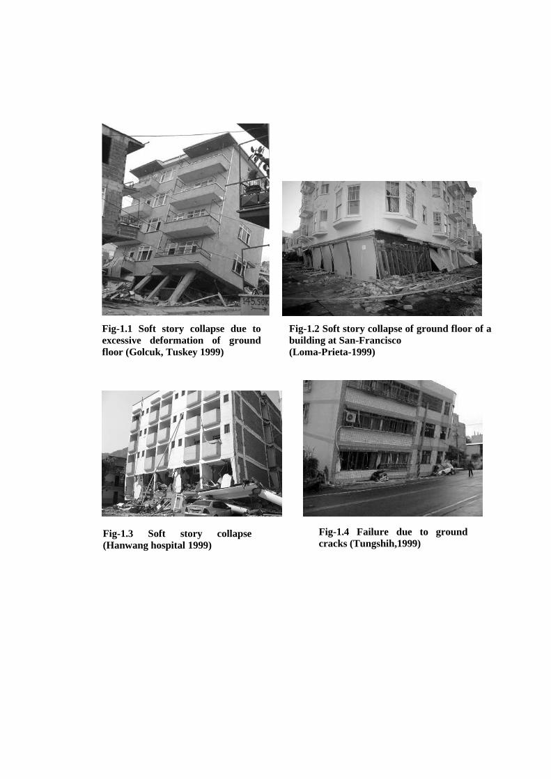
Fig-1.2 Soft story collapse of ground floor of a
building at San-Francisco
(Loma-Prieta-1999)
Fig-1.1 Soft story collapse due to
excessive deformation of ground
floor (Golcuk, Tuskey 1999)
Fig-1.4 Failure due to ground
cracks (Tungshih,1999)
Fig-1.3 Soft story collapse
(Hanwang hospital 1999)
1.3 OBJECTIVE AND SCOPE OF THE STUDY
The objective of the present study is to sort out the base shear modification under the
action of earthquake load on masonry infilled RC frame having open ground floor.
The elementary goal is to feature on the consideration of combined structural effect of
infill with soft ground floor compared to bare frame. The specific objectives of the
investigation can be summarized as follows;
To develop a 3D finite element model of building with infill on upper floors
and soft ground floor.
Modeling of infill as diagonal struts and applied in different percentage
randomly on frame system.
To analyze the building system (featuring certain variables) by both
Equivalent Static Force Method (ESFM) and dynamic Response Spectrum
Method (RSM) following Bangladesh National Building Code (BNBC, 1993).
Comparison of base shear values by the two methods for certain structural
variables.
To analyze the variation in base shear for same percentage of randomly
applied infill in different patterns.
To obtain some modification factor for base shear respective to the traditional
design value by ESFM.
To study the change in modification factor with change of span no. and length.
There are a number of factors and variables on which the study can be carried but
here, the base shear value for earthquake load on infilled structure will be focused and
analyzed. Buildings with regular and symmetric geometry will be considered only.
1.4 ASSUMPTIONS FOR MODELING SIMPLICITY
The investigation is based on the following assumptions;
Material is linearly elastic and isotropic
All dead and live loads are taken as vertical while only earthquake load is
taken as lateral

Infill is modeled as diagonal strut with same homogeneous material properties
of concrete
Dead load including infill (partition wall) mass contribution is modeled as
mass element with vertical acceleration only
1.5 ORGANIZATION OF THE THESIS
The whole thesis is organized into five chapters. Chapter 1 introduces the present
study while Chapter 2 focuses on the review of relevant theories, methods of analysis
and behavior of RC frame with infill. Chapter 3 illustrates the methodology of finite
element modeling by suitable program package. Chapter 4 is organized with analysis
and discussion on output results based on various parameters. Chapter 5 is for the
summary of findings from current study and concluding recommendations for future
investigation and extension of this work.
CHAPTER 2
LITERATURE REVIEW
2.1 INTRODUCTION
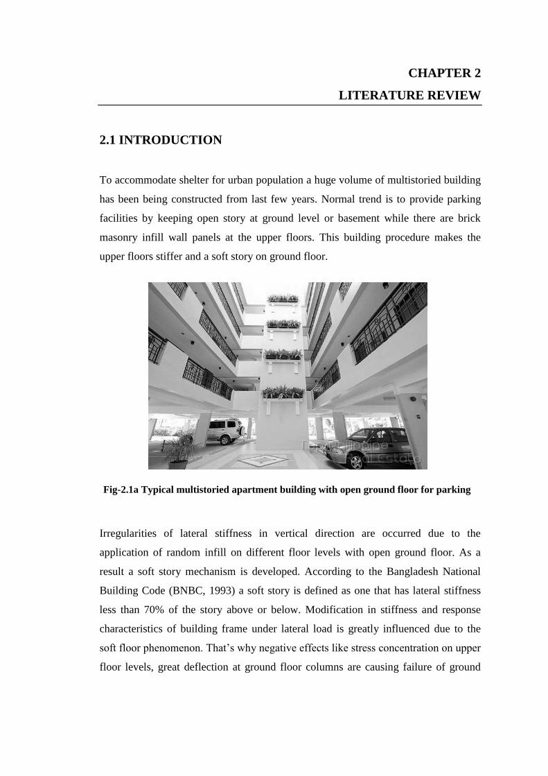
To accommodate shelter for urban population a huge volume of multistoried building
has been being constructed from last few years. Normal trend is to provide parking
facilities by keeping open story at ground level or basement while there are brick
masonry infill wall panels at the upper floors. This building procedure makes the
upper floors stiffer and a soft story on ground floor.
Irregularities of lateral stiffness in vertical direction are occurred due to the
application of random infill on different floor levels with open ground floor. As a
result a soft story mechanism is developed. According to the Bangladesh National
Building Code (BNBC, 1993) a soft story is defined as one that has lateral stiffness
less than 70% of the story above or below. Modification in stiffness and response
characteristics of building frame under lateral load is greatly influenced due to the
soft floor phenomenon. That’s why negative effects like stress concentration on upper
floor levels, great deflection at ground floor columns are causing failure of ground
Fig-2.1a Typical multistoried apartment building with open ground floor for parking
facility
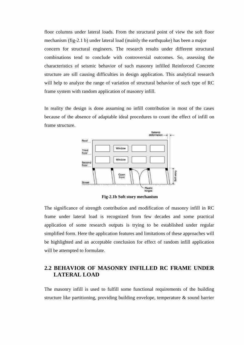
floor columns under lateral loads. From the structural point of view the soft floor
mechanism (fig-2.1 b) under lateral load (mainly the earthquake) has been a major
concern for structural engineers. The research results under different structural
combinations tend to conclude with controversial outcomes. So, assessing the
characteristics of seismic behavior of such masonry infilled Reinforced Concrete
structure are sill causing difficulties in design application. This analytical research
will help to analyze the range of variation of structural behavior of such type of RC
frame system with random application of masonry infill.
In reality the design is done assuming no infill contribution in most of the cases
because of the absence of adaptable ideal procedures to count the effect of infill on
frame structure.
The significance of strength contribution and modification of masonry infill in RC
frame under lateral load is recognized from few decades and some practical
application of some research outputs is trying to be established under regular
simplified form. Here the application features and limitations of these approaches will
be highlighted and an acceptable conclusion for effect of random infill application
will be attempted to formulate.
2.2 BEHAVIOR OF MASONRY INFILLED RC FRAME UNDER
LATERAL LOAD
The masonry infill is used to fulfill some functional requirements of the building
structure like partitioning, providing building envelope, temperature & sound barrier
Fig-2.1b Soft story mechanism
etc. The structural contribution of masonry infill under seismic load is not considered
correctly due to the lack of analytical knowledge.
Researchers (Klingner and Bertero in 1978, Bertero and Brokkenc in 1983, Mehrabi
et al. in 1996) have concluded that the proper and careful use of infill can
significantly increase the strength and stiffness of structure subjected to seismic
excitations. To ensure the adequate safety of building the selection of infill location
must be such that the torsional and soft story effect is minimized under architectural
restrictions.
In 3D RC frame system the confined masonry infill walls contribute a vital part on
resisting lateral seismic loads on building. To develop a logical approach of designing
such RC frames the behavior of masonry infill is closely investigated (Moghaddam
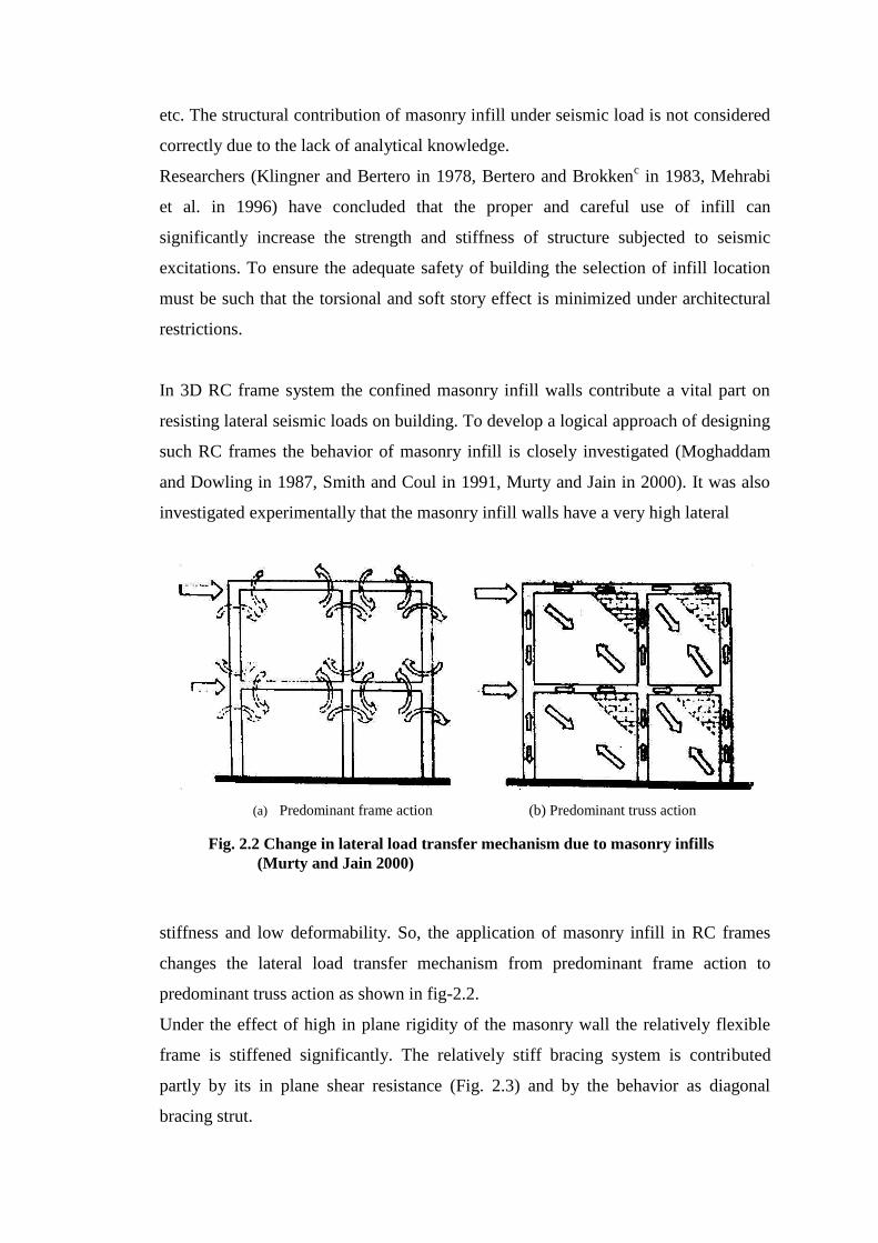
and Dowling in 1987, Smith and Coul in 1991, Murty and Jain in 2000). It was also
investigated experimentally that the masonry infill walls have a very high lateral
stiffness and low deformability. So, the application of masonry infill in RC frames
changes the lateral load transfer mechanism from predominant frame action to
predominant truss action as shown in fig-2.2.
Under the effect of high in plane rigidity of the masonry wall the relatively flexible
frame is stiffened significantly. The relatively stiff bracing system is contributed
partly by its in plane shear resistance (Fig. 2.3) and by the behavior as diagonal
bracing strut.
(a) Predominant frame action (b) Predominant truss action
Fig. 2.2 Change in lateral load transfer mechanism due to masonry infills
(Murty and Jain 2000)
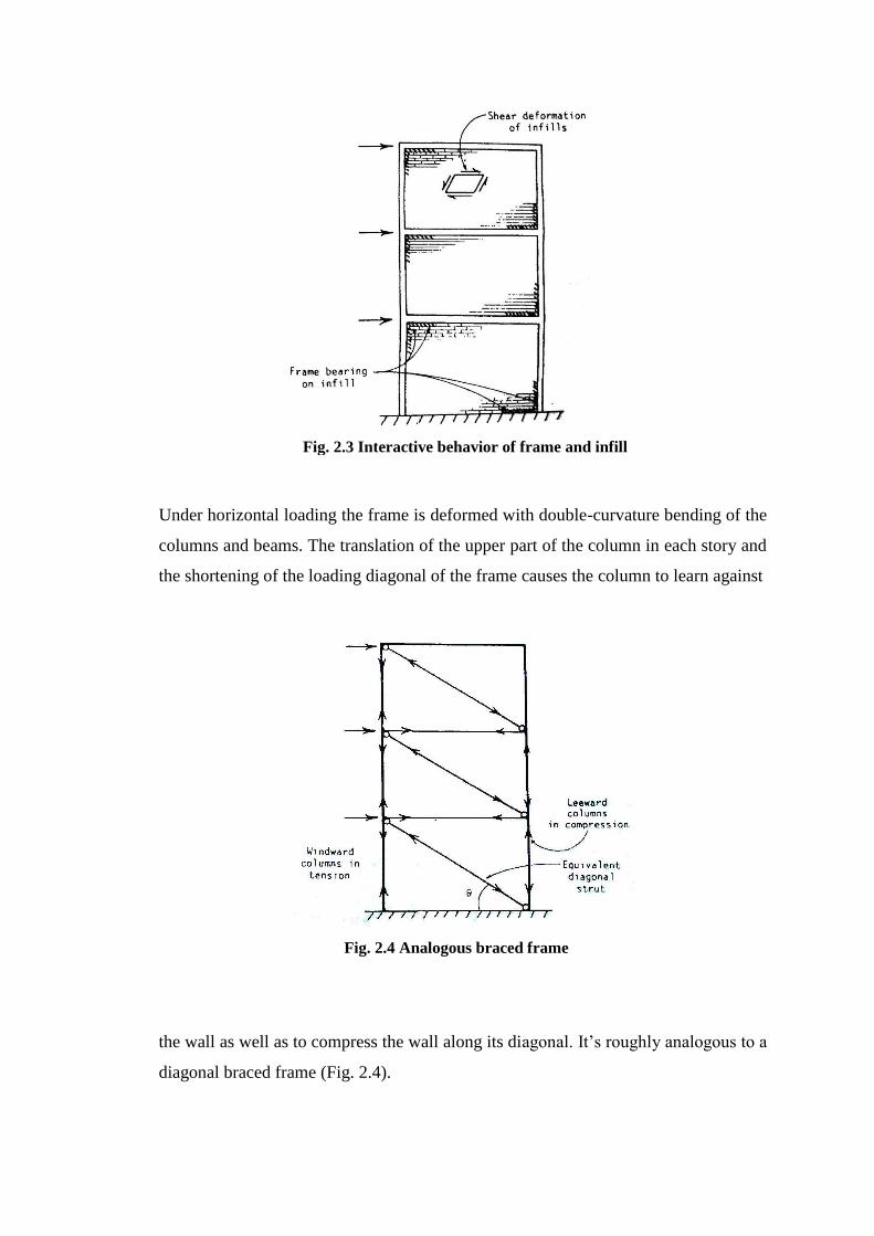
Under horizontal loading the frame is deformed with double-curvature bending of the
columns and beams. The translation of the upper part of the column in each story and
the shortening of the loading diagonal of the frame causes the column to learn against
the wall as well as to compress the wall along its diagonal. It’s roughly analogous to a
diagonal braced frame (Fig. 2.4).
Fig. 2.3 Interactive behavior of frame and infill
Fig. 2.4 Analogous braced frame
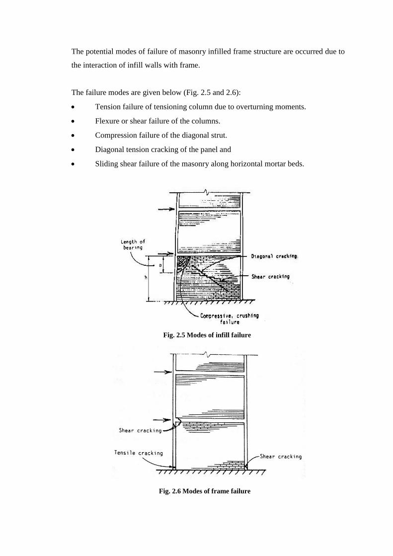
The potential modes of failure of masonry infilled frame structure are occurred due to
the interaction of infill walls with frame.
The failure modes are given below (Fig. 2.5 and 2.6):
Tension failure of tensioning column due to overturning moments.
Flexure or shear failure of the columns.
Compression failure of the diagonal strut.
Diagonal tension cracking of the panel and
Sliding shear failure of the masonry along horizontal mortar beds.
Fig. 2.5 Modes of infill failure
Fig. 2.6 Modes of frame failure
The perpendicular tensile stresses are caused by the divergence of the compressive
stress trajectories on the opposite sides of the leading diagonal as they approach the
mid region of the infill. The shear failure of wall steps down through the joints of
masonry and participated by the horizontal shear stresses in the bed joints. The
diagonal cracking of the wall is through the masonry along a line or line parallel to
the loading diagonal and caused by tensile stresses perpendicular to the loading
diagonal. The perpendicular tensile stresses caused by the divergence of the
compressive stress trajectories on opposite sides of the loading diagonal as they
approach the middle region of the infill. The diagonal cracking is initiated and
spreads from the middle of the infill while the tensile stresses are at maximum
tending to stop near the compression corners, where the tension is suppressed.
The nature of the forces in the frame can be understood by referring to the analogous
braced frame shown in (fig. 2.4). The windward column or the column facing the
seismic load first is in tension and the leeward column or the other side of the
building facing seismic load last is in compression. Since the infill bears on the frame
not as exactly a concentrated force at the corners, but over the short lengths of the
beam and column adjacent to each compression corner, the frame members are
subjected also to transverse shear and a small amount of bending. Consequently the
frame members or their connections are liable to fail by axial force or shear and
especially by tension at the base of the windward column.
2.3 COMPUTATIONAL MODELLING AND ANALYSIS OF
INFILLED FRAME
Different types of modeling approach were attempted for featuring infill
characteristics in RC frame. Holmes (1961) replaced the infill by an equivalent pin-
jointed diagonal strut. Smith (1962) conducted a series of tests on laterally loaded
square mild steel frame models infilled with micro-concrete. From the model
deformation results he concluded that the wall could be replaced by an equivalent
diagonal strut connecting the loaded corners. As the elastic methods were not able to
fully feature the actual characteristics of infilled frames, attention was paid to the
theories of plasticity. Wood (1958) extended the limit analysis of plasticity with the
assumption of perfect plasticity. Recently a method was developed by Saneinejad
(1995) that allows for interface shear forces and both the elastic and plastic behavior
of material. The stiffness of structural system is determined with variations in
geometrical and mechanical characteristics. The analysis is carried out utilizing the
boundary element method (BEM) for the infill and dividing the frame into finite
elements, so as to transform the mutual interactions of the two subsystems into
stresses distributed along the boundary for the infill and into nodal actions for the
frame. Some of the methods of analyzing the infilled frames are discussed in
following sections.
2.3.1 Equivalent Diagonal Strut Method
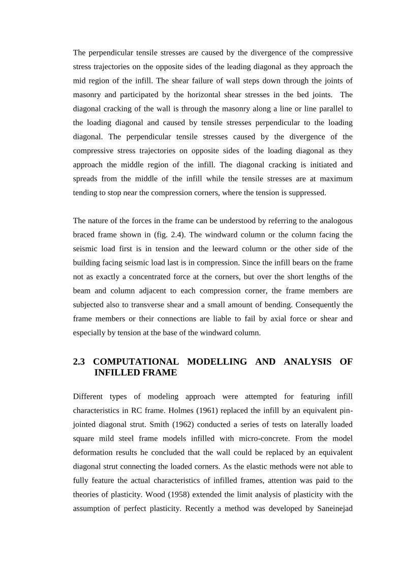
The first published research on modeling of infill panel as an equivalent diagonal
strut method was applied by Holmesh (1961). He assumed that the infill wall acts as
diagonal compression strut as shown in (fig-2.7) of the same thickness and elastic
modulus as the infill with a width equal to one-third the diagonal length. He also
concluded that at the infill failure, the lateral deflection of the infilled frame is small
compared to the deflection of the corresponding bare frame.
Fig. 2.7 Material modeling of masonry infill as diagonal strut
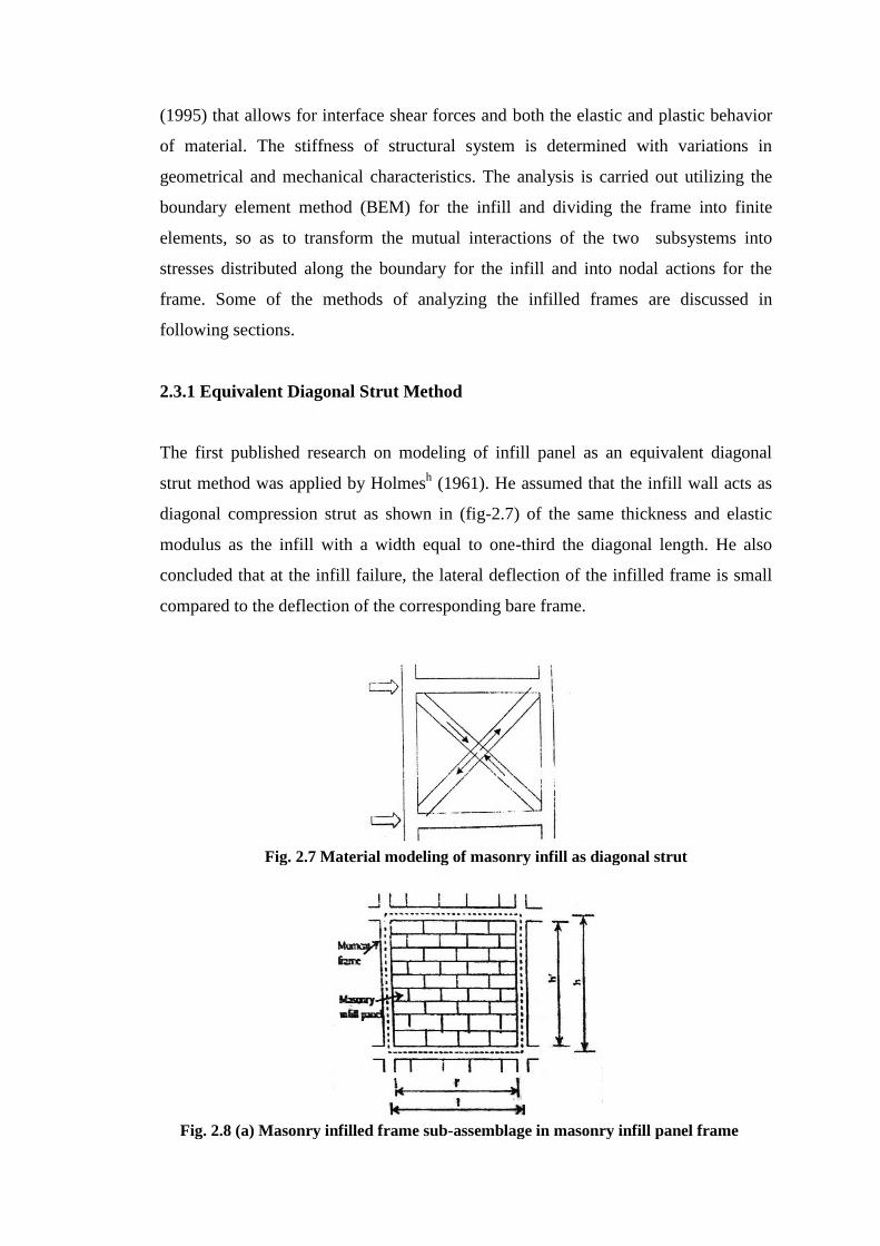
Fig. 2.8 (a) Masonry infilled frame sub-assemblage in masonry infill panel frame
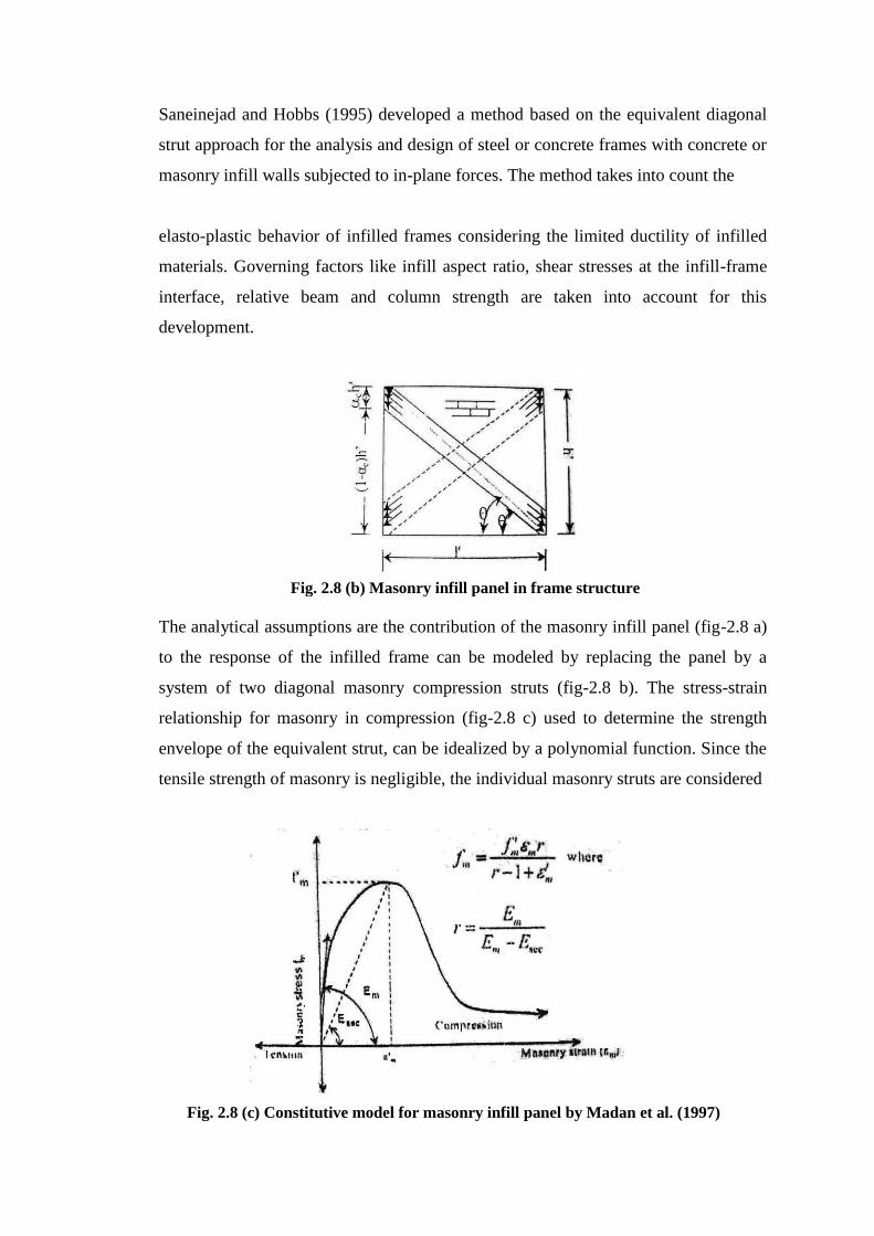
Saneinejad and Hobbs (1995) developed a method based on the equivalent diagonal
strut approach for the analysis and design of steel or concrete frames with concrete or
masonry infill walls subjected to in-plane forces. The method takes into count the
elasto-plastic behavior of infilled frames considering the limited ductility of infilled
materials. Governing factors like infill aspect ratio, shear stresses at the infill-frame
interface, relative beam and column strength are taken into account for this
development.
The analytical assumptions are the contribution of the masonry infill panel (fig-2.8 a)
to the response of the infilled frame can be modeled by replacing the panel by a
system of two diagonal masonry compression struts (fig-2.8 b). The stress-strain
relationship for masonry in compression (fig-2.8 c) used to determine the strength
envelope of the equivalent strut, can be idealized by a polynomial function. Since the
tensile strength of masonry is negligible, the individual masonry struts are considered
Fig. 2.8 (b) Masonry infill panel in frame structure
Fig. 2.8 (c) Constitutive model for masonry infill panel by Madan et al. (1997)
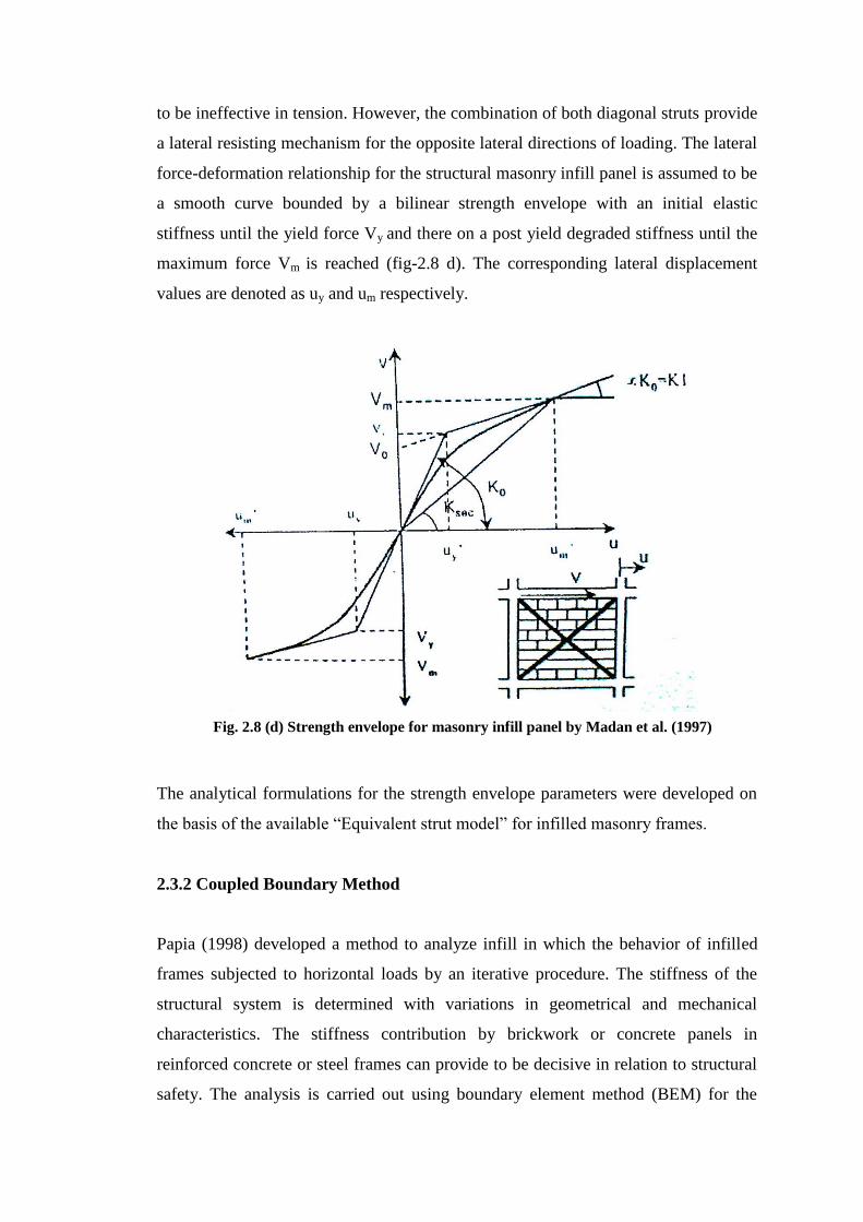
to be ineffective in tension. However, the combination of both diagonal struts provide
a lateral resisting mechanism for the opposite lateral directions of loading. The lateral
force-deformation relationship for the structural masonry infill panel is assumed to be
a smooth curve bounded by a bilinear strength envelope with an initial elastic
stiffness until the yield force Vy and there on a post yield degraded stiffness until the
maximum force Vm is reached (fig-2.8 d). The corresponding lateral displacement
values are denoted as uy and um respectively.
The analytical formulations for the strength envelope parameters were developed on
the basis of the available “Equivalent strut model” for infilled masonry frames.
2.3.2 Coupled Boundary Method
Papia (1998) developed a method to analyze infill in which the behavior of infilled
frames subjected to horizontal loads by an iterative procedure. The stiffness of the
structural system is determined with variations in geometrical and mechanical
characteristics. The stiffness contribution by brickwork or concrete panels in
reinforced concrete or steel frames can provide to be decisive in relation to structural
safety. The analysis is carried out using boundary element method (BEM) for the
Fig. 2.8 (d) Strength envelope for masonry infill panel by Madan et al. (1997)
infill and opportunely dividing the frame into finite elements, so as to transform the
mutual interactions of the two systems into stresses distributed along the boundary for
the infill and nodal actions for the frame. This makes it possible to take into account
the separation arising between the two substructures when mutual tensile stresses are
involved.
At first, infill without opening are considered, using BEM with constant elements for
two dimensional problems in elasticity. Then the result is compared with those
obtained using the simplified equivalent pin-jointed strut model.
2.3.3 Plasticity Model
A method of analyzing of infill based on plasticity theory which is adopted to
describe the inelastic behavior utilizes modern algorithmic concepts, including an
implicit Euler background return mapping scheme, a local Newton-Raphson and a
consistent tangential stiffness matrix. It features tensile fracture energy and
compressive fracture energy. The framework of plasticity theory is generally
adequate to apply to both isotropic and anisotropic behavior. In anisotropic plasticity
models the hardening behavior has been simulated with the fraction model. An
accurate analysis of anisotropic materials requires a description for all stress states.
The yield criterion proposed for this study combines the advantages of modern
plasticity concepts with a powerful representation of anisotropic material behavior,
which includes different hardening/softening behavior along each material axis. For
modeling orthotropic material behavior, a Hill-type criterion for compression and
Rankine-type criterion for tension are proposed (fig). The model is formulated in such
a way that each internal parameter is related to two independent fracture energies
along each material axis.
2.3.4 Approximate Method
An approximate method has been suggested by Smith and Coull (1985). It may be
classified as elastic approach except for the criterion used to predict the infill
crushing. A plastic type masonry infill is assumed. Stresses in the infill relating to
shear failure of the infill is related to the combination of of shear and normal stresses
included at points in the infill when the frame bears on it as the structure is subjected
to the external lateral shear.
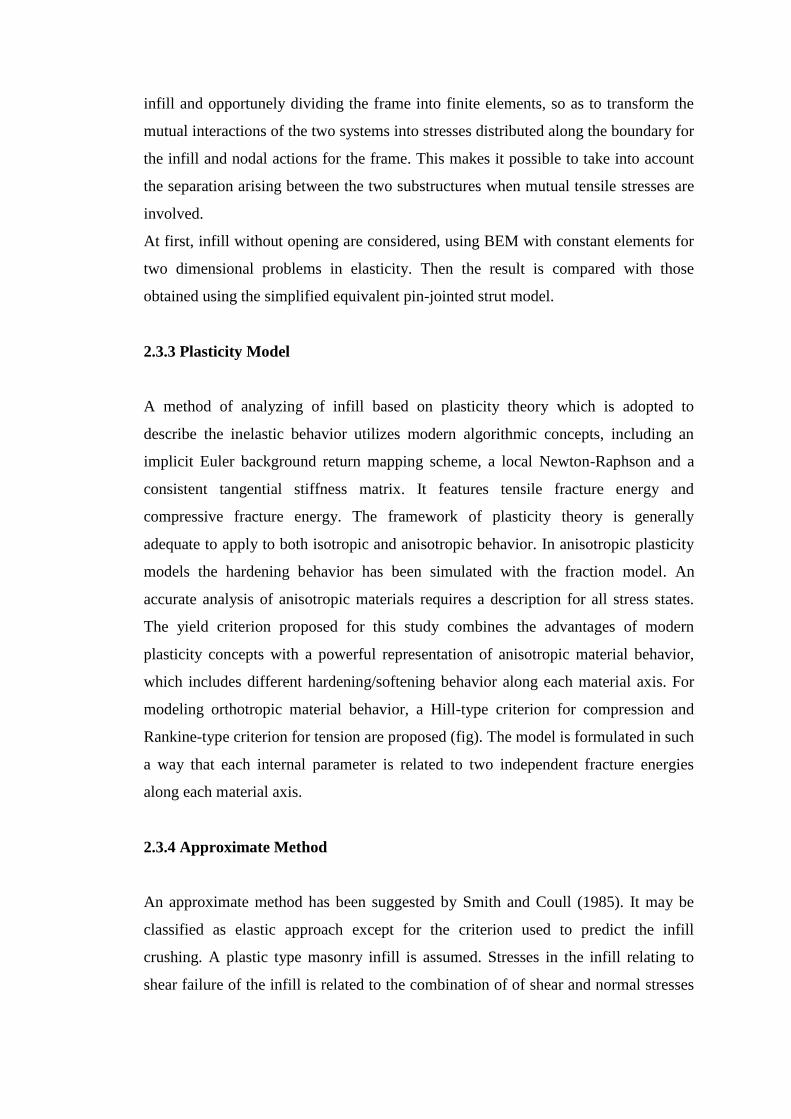
An extensive series of plane stress membrane finite-element analysis has shown that
the critical values of this combination of stresses occur at the centre of the infill and
that they can be expressed empirically by,
Shear stress, τxy=Lt
Q43.1 2.1
Vertical Compression stress, 𝛔y= Lt
QLh )2.0/8.0( 2.2
Stresses in the infill relating to diagonal tension failure are related to the maximum
value of diagonal tensile stress in the infill. This occurs at the centre of the infill and
based on the result of the analysis it may be expressed empirically as
Diagonal Tensile stress, 𝛔d= Lt
Q58.0 2.3
Where,
Q is the horizontal shear load applied by the frame to the infill of length L, height h and
thickness t.
These stresses are governed mainly by the proportion of the infill. They are little
influenced the stiffness properties of the frame because they occur at the centre of the
infill away from the region of contact with the frame.
Fig. 2.9 Proposed composite yield criterion with iso-shear stress lines

2.4 CHOICE OF MODEL
Among the computational models discussed previously the approximate method is
primarily intended for preliminary through manual calculation. Plasticity and
Boundary Element Method are based on continuum plasticity approach in which the
infill is modeled as an assemblage of several plane stress elements via special
interface element. Such model is suitable for detailed or micro level study of the
stress, strain, damage, cracks, failure at various locations of primary interest of the
infill panels. Such model is not suitable for investigating overall structural behavior
of building where infill is only a structural component. In that case equivalent strut
model is more suitable. The equivalent diagonal strut model using time rate
independent constitutive features can be used for a static non linear analysis as well as
time history analysis. The same model can be featured with hysteretic formulation for
static monotonic analysis and quasi-static cyclic analysis. The equivalent diagonal
strut model considers the entire infill panel as a single unit and takes into account
only the equivalent global behavior. As a result the approach does not permit study of
local effect such as frame iteration within the individual infilled frame sub-
assemblage. Plasticity and Boundary Element approach are used to capture the spatial
and temporal variations of local conditions within the infill. However the equivalent
strut model allows for adequate equivalence of the nonlinear force deformation
response of the structure and individual components under lateral load. Thus the
macro model is better suited for representing the behavior of infill in nonlinear time-
history analysis of large or complex structures with multiple components. Therefore,
the equivalent diagonal strut model is selected for modeling and analyzing the
characteristics of infilled frames.
2.5 MODELING FOR EQUIVALENT DIAGONAL STRUT
APROACH
For the infilled masonry frame shown in fig, the maximum lateral force Vm and
corresponding displacement um in the infill masonry panel (Saneinejad et al. 1995)
are
Vm± = Ad f´m cosθ ≤
cos)tan45.01(
lvt≤
cos
83.0 lt 2.4

um± =
cos
dm L 2.5
where, t = thickness of the panel
l´ = lateral dimension of infill panel
f´m = masonry prism strength
ε´m = corresponding strain
θ = inclination of diagonal strut
v = basic shear strength of masonry
Ad and ld = area and length of the equivalent diagonal struts respectively
calculated as,
Ad =
cos
)1(c
bb
c
ccc
ftl
fth
≤ 0.5cos
c
a
f
fht
2.6
Ld = ])1[( 222 lhc 2.7
The quantities αc, αb, 𝛔c, τb, fa and fc depend on the geometric and material properties
of the frame and infill panel. These can be estimated using the formulations of the
‘Equivalent Strut Model’ proposed by Saneinejad et al. (1995). The lateral yield force
Vy and displacement of the infill panel may be calculated from geometry
Vy± =
α)(1
uαK-Vm m0
2.8
um±
= )1(
uK-Vm m0
2.9
The initial stiffness K0 of the infill masonry panel may be estimated using the
following formula (Manad et al. 1997)
K0 = 2(Vm/um) 2.10
The parameters Vm, Vy, um, uy, K0 are shown in figure 2.8.
2.5.1 Beam and Column Moment Capacity
To find out the stiffness of equivalent strut (K0) it requires to determine the following
properties of beam, column and joint,
Mpc = Plastic resisting moment of column
Mpb = Plastic resisting moment of beam
Mpj = Plastic resisting moment of joint
To determine the Mpc and Mpb it requires to provide reinforcement in beams and
columns. These moments can be calculated on the basis of the following formulae,
Mn = Asfy(d-2
a) 2.11
And a = bf85.0
fA
c
ys
2.12
2.5.2 Determination of Equivalent Strut Stiffness
The equivalent strut model proposed by Saneinejad and Hobbs (1995) and later
modified by Madan et al. (1997) is discussed here in details.
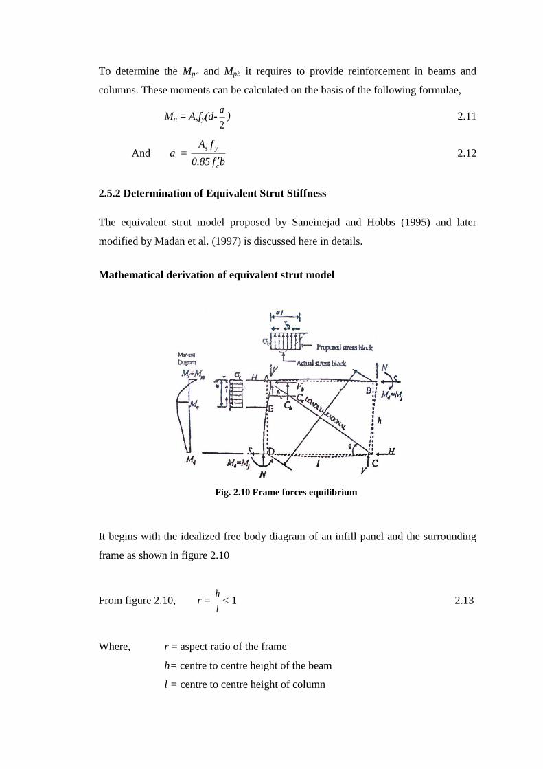
Mathematical derivation of equivalent strut model
It begins with the idealized free body diagram of an infill panel and the surrounding
frame as shown in figure 2.10
From figure 2.10, r = l
h< 1 2.13
Where, r = aspect ratio of the frame
h= centre to centre height of the beam
l = centre to centre height of column
Fig. 2.10 Frame forces equilibrium
r´ = l
h
< 1 2.14
Where, h’= height of infill
l’ = length of infill
tanθ = l
h 2.15
tanθ = l
h
2.16
Where, θ = inclination of diagonal strut
fc = 0.6𝜙 f´m 2.17
𝜙 = constant valuing 0.65
f´m= compressive strength of masonry
αch ≤ 0.4h 2.18
αbl ≤ 0.4l 2.19
Where, α = normalized length of contact
c,b = subscripts designated for columns and beams respectively
The length of the proposed stress blocks (figure 2.10) may not exceed 0.4 times the
length corresponding infill dimensions.
Fc = μr2Cc 2.20
Fb = μCb 2.21
Where, C,F = frame-infill contact normal and shear force (figure 2.10)
μ = coefficient of friction of the frame-infill interface
MA = MC =Mpj 2.22
Where, MA and MC = bending moment at loaded corners (points A and C in
figure 2.10),

Mpj = least of the beam, the column and their connection plastic resisting moment
called the joint plastic moment.
MD = MB = Mj < Mpj 2.23
Mc = βcMpc 2.24
Mb = βbMpb 2.25
Where, MB and MD = bending moments at the unloaded corners (figure 2.10)
Mj =either of these values.
Mc and Mb = maximum intermediate elastic moment of column and beam.
βc ≤ βb = 0.2 2.26
βb ≤ β0 = 0.2 2.27
Where, β0 = nominal or rather upper bounded value of the reduction factor
Let, h´ = h and l´ = l
Frame forces equilibrium requires the following;
V = H tanθ 2.28
H = Cc + Fb + 2S 2.29
V = Cb + Fc + 2N 2.30
Where, H and V= horizontal and vertical components of the external forces.
S and N = Shear and axial forces respectively over the uncontacted length of
the column.
𝛔 and τ = proposed uniform frame-infill contact normal and shear forces.
θ = angle of the infill diagonal.
Rotational equilibrium of the infill requires the following;
Cc(22
hhc ) – Fc ×
2
l – Cb(
22
llb ) + Fb ×
2
h = 0 2.31
Where, Cc = 𝛔ctαch
Cb = 𝛔btαbl

Fc = τctαcl
Fb = τbtαbl
Taking the static moment of the forces acting on the column and beam about point A,
S = - 0.5𝛔ctαc2h+
h
MM jpj 2.32
N = - 0.5𝛔btαb2l+
l
MM jpj 2.33
Substituting for contact forces, Cc and Fb and also column shear force, S into 2.29
leads the collapse load as follows;
H = 𝛔ct(1-αc)αch+τbtαbl+2h
MM jpj )( 2.34
At peak load the infill is subjected to failure resulting from combined normal and
shear stress acting on the contact surfaces in the loaded corners. The well known
Tresca hexagonal yield criterion described by Chen (1982) is mathematically
convenient for this combination and is given by
𝛔2+3τ
2 = fc
2 2.35
Where, fc = effective compressive strength of the infill.
Assuming rectangular stress block as shown in figure 2.12 can be written also in
terms of the contact stresses as follows;
τc = μr2𝛔c 2.36
τb = μ𝛔b 2.37
This relation would be satisfied only with the real contact stresses as follows
If Ac > Ab, then, 𝛔b = 𝛔c and 𝛔c = 𝛔c0 (Ab/Ac) 2.38
If Ac < Ab, then, 𝛔c = 𝛔c0 and 𝛔b = 𝛔b0 (Ac/Ab) 2.39
Where, Ac = r2 𝛔c0αc(1- αc – μr) 2.40
Ab = 𝛔b0αb(1- αb - μr) 2.41
The actual compressive strength of masonry infill depends on the direction of stresses
and it can be found by;
fa = fc[1-(Ld/40t)2] 2.42
The effective length of diagonal strut;
Ld = ])1[( 222 lhc 2.43
Where, Ld is not greater than 40t and fc is effective compressive strength of
masonry.
Ad =
cos
)1(c
bb
c
ccc
ftl
fth
≤ 0.5cos
c
a
f
fht
2.44
Where, Ad =the cross-sectional area of the diagonal strut for effective
compressive strength, fc
Vm±
≤ Adf´mcos ≤
cos)tan45.01(
lvt≤
0.83
cos
lt
2.45
um± =
cos
dml 2.46
The initial stiffness, K0 of the infill masonry panel may be estimated using the
following formula (Madan ey al. 1997);
K0 = 2(Vm/um) 2.47
2.6 EFFECT OF EARTHQUAKE ON BUILDING FRAME WITH
SOFT STORY
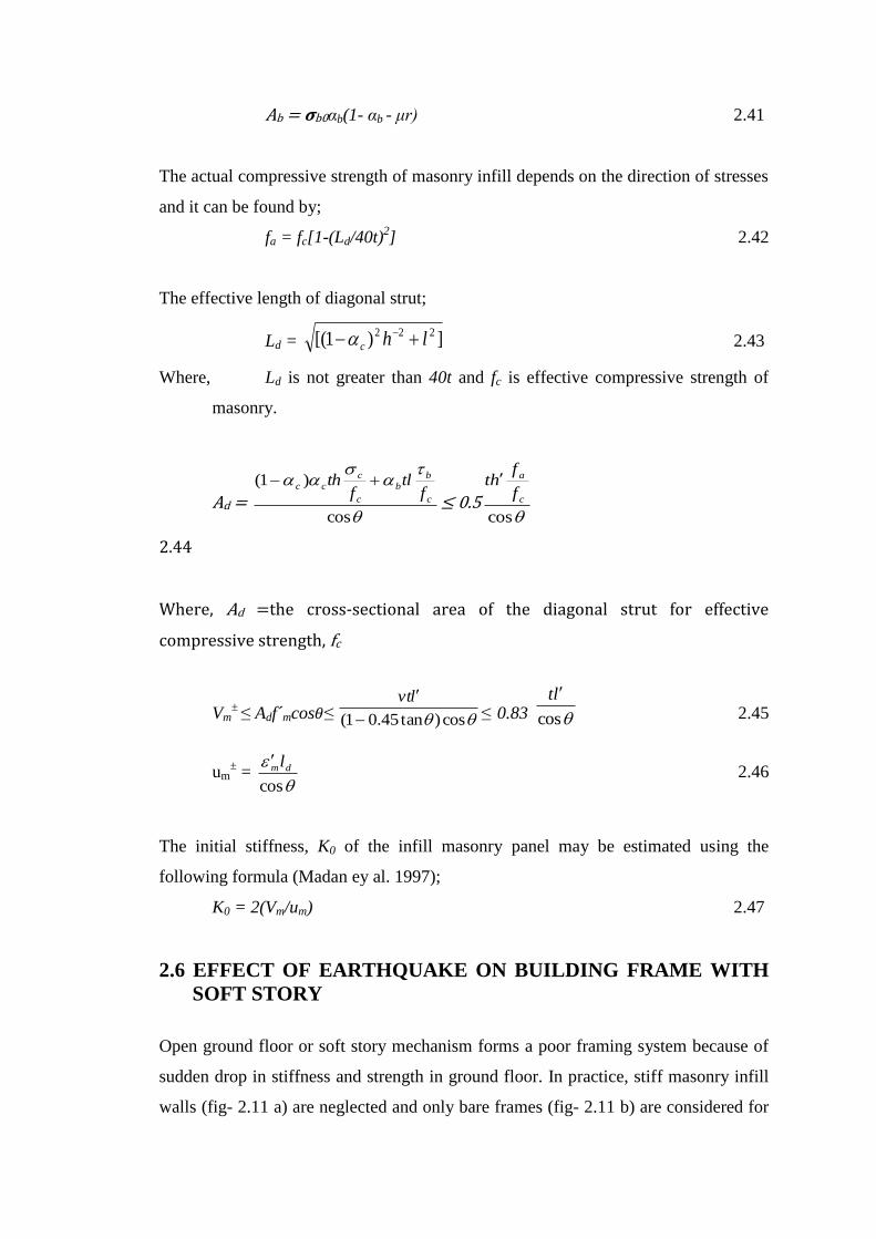
Open ground floor or soft story mechanism forms a poor framing system because of
sudden drop in stiffness and strength in ground floor. In practice, stiff masonry infill
walls (fig- 2.11 a) are neglected and only bare frames (fig- 2.11 b) are considered for
design consideration. The mode shapes vary based on the location and quantity of
infill on upper floor levels with soft floor on ground level.
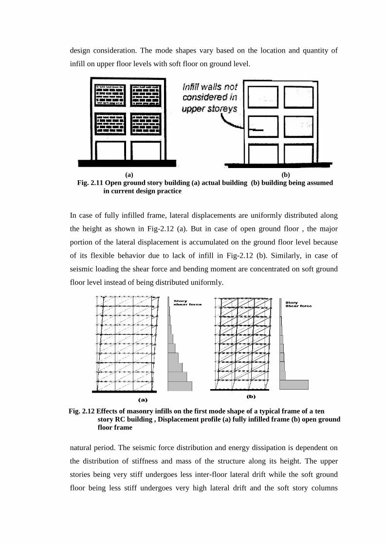
In case of fully infilled frame, lateral displacements are uniformly distributed along
the height as shown in Fig-2.12 (a). But in case of open ground floor , the major
portion of the lateral displacement is accumulated on the ground floor level because
of its flexible behavior due to lack of infill in Fig-2.12 (b). Similarly, in case of
seismic loading the shear force and bending moment are concentrated on soft ground
floor level instead of being distributed uniformly.
Total seismic loading experienced by a building during earthquake depends on its
natural period. The seismic force distribution and energy dissipation is dependent on
the distribution of stiffness and mass of the structure along its height. The upper
stories being very stiff undergoes less inter-floor lateral drift while the soft ground
floor being less stiff undergoes very high lateral drift and the soft story columns
(a) (b)
Fig. 2.11 Open ground story building (a) actual building (b) building being assumed
in current design practice
Fig. 2.12 Effects of masonry infills on the first mode shape of a typical frame of a ten
story RC building , Displacement profile (a) fully infilled frame (b) open ground
floor frame
dissipate most of the seismic energy in the process of plastic hinges. Thus the
possibility and risk of collapse is very high in case of soft story under lateral loads.
The feature of soft story mechanism is not considered in the present method of
analysis for earthquake load. In static method we only consider the first mode of
vibration (that’s suitable for regular bare frames) while the behavior of infilled and
irregular frames are far more complicated and uncertain. That’s why the dynamic
analysis is helpful to account for the other modes of vibration and consider the
irregularity of stiffness features in building frame caused by random distribution of
infill on upper floors. If we can consider the true dynamic features of the frame
system then the design will be safer and adequate.
2.7 CONSIDERATION OF SOFT STORY IN DIFFERENT
BUILDING CODES
Building codes specify the design and construction requirements ensuring public
safety from structural failure and loss of life and wealth. Because of the differences in
magnitude of earthquake, geological formations, construction types, economical
development and other features the seismic design aspects are different in different
building codes. The national building codes of different countries can be classified in
two broad categories for our discussion. First are those Codes do not consider the
features of Masonry Infill walls while designing RC frames and the others are those
consider the features of Masonry Infill walls while designing RC frames.
Modification factor = static
RSM
V
V
Where, RSMV = Base shear by RSM
STATICV = Base shear by static analysis
2.7.1 Without Considering Soft Story Phenomenon
There are some advantageous features of masonry infill walls like high initial lateral
stiffness, cost effectiveness, ease in construction etc. Proper location and distribution
of infill application can increase the defense tremendously against seismic action.
These codes want to ensure the safety through proper layout and quality control
instead of considering the soft story features directly. In most cases the codes state
that the regular geometry of structures perform better against earthquake loads while
unsymmetrical application of MI walls introduce irregularities in structure. In case of
low rise buildings and low risk zone for seismic danger the codes normally
recommend static analysis while for high rise structures dynamic analysis is
recommended for adequate modeling and to obtain actual seismic design force.
Natural period of vibration is an important factor for seismic force design. Normally
the natural period is higher in case of bare frames than masonry infilled RC frames.
That’s why the design force for MI RC frames is higher than bare frames. There are
some suggestions in different codes about the natural period in case of MI-RC frames.
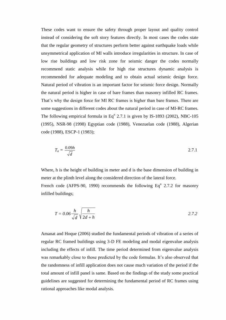
The following empirical formula in Eqn 2.7.1 is given by IS-1893 (2002), NBC-105
(1995), NSR-98 (1998) Egyptian code (1988), Venezuelan code (1988), Algerian
code (1988), ESCP-1 (1983);
Ta = d
h09.0 2.7.1
Where, h is the height of building in meter and d is the base dimension of building in
meter at the plinth level along the considered direction of the lateral force.
French code (AFPS-90, 1990) recommends the following Eqn 2.7.2 for masonry
infilled buildings;
T = 0.06hd
h
d
h
2 2.7.2
Amanat and Hoque (2006) studied the fundamental periods of vibration of a series of
regular RC framed buildings using 3-D FE modeling and modal eigenvalue analysis
including the effects of infill. The time period determined from eigenvalue analysis
was remarkably close to those predicted by the code formulas. It’s also observed that
the randomness of infill application does not cause much variation of the period if the
total amount of infill panel is same. Based on the findings of the study some practical
guidelines are suggested for determining the fundamental period of RC frames using
rational approaches like modal analysis.
2.7.2 Considering Soft Story Phenomenon
Vertical irregularities are introduced in MI-RC frames due to the reduction or absence
of MI in particular stories compared to other adjacent stories. This matter creates
irregularities in mass, stiffness, strength along the height of the structure. As a result
the design of the beam and column is needed to be modified according to
modification of base shear value under lateral load due to formation of irregularities
for random MI application. There are some building codes where instruction for
design modification for soft story phenomenon is given.
The Indian seismic code (IS-1893 2002) requires members of the soft story (story
stiffness less than 70% of that in the story above or less than 80% of the average
lateral stiffness of the three stories above) to be designed for 2.5 times the seismic
story shears and moments obtained without considering the effects of MI in any story.
The factor of 2.5 is specified for all the buildings with soft stories irrespective of the
extent of irregularities. The other option is to provide symmetric RC shear walls
designed for 1.5 times the design story shear force in both directions of the building
as far away from the center of the building as feasible.
Costa Rican code (1986) requires that all structural resisting system must be
continuous from the foundation to the top of the building and stiffness of a story must
not be less than 50% of that of the story below.
Mezzi (2004) illustrated soft story to be very dangerous from seismic viewpoint as
the lateral response of these buildings is characterized by a large rotation ductility
demand concentrated at the extreme sections of the columns of the ground floors,
while the superstructure behaves like a quasi-rigid body. A solution was proposed for
the preservation of a particular architectonic double soft story configuration.
CHAPTER 3
FINITE ELEMENT MODELING OF INFILL FRAME
3.1 INTRODUCTION
In this chapter the full structural modeling of 3D MI-RC frame is made including
individual modeling like beam, column, slab, infill, load etc. with proper support
condition. To model the masonry infill, link element is taken as diagonal strut and for
load application, mass element is chosen accordingly. For the analysis both
equivalent static force method (according to BNBC) and RSM is considered. The
comparison of effect of infill between ESFM and RSM is done to asses the real
structural characteristics of soft story.
3.2 SOFTWARE FOR FINITE ELEMENT ANALYSIS
A good number of software packages are available for finite element analysis in civil
engineering field. Some of those are designed for specialized structural analysis and
specific behavioral characteristics. Among them ANSYS program package has more
advantageous features for the analysis performed in this research. So, the ANSYS
10.0 package has been selected for its vastness, flexibility and ease in use as finite
element analysis tool.
3.3 ASSUMPTIONS FOR MODELING SIMPLIFICATION
We assumed linearly elastic homogeneous material for the RC frame that is always
steel reinforced in reality. According to ACI recommendation, the analysis results for
RC frame are accurate enough for this simplification only if appropriate properties of
concrete are considered. The structural property of masonry infill is modeled as
compressive diagonal strut assuming negligible tensile strength of masonry. This
simplification is fare enough to resist the lateral load by compression only.

3.4 CHARACTERIZATION OF STRUCTURAL COMPONENTS
IN MODEL
3.4.1 BEAM4 (3-D Elastic Beam) for Beam and Column
Element Description
BEAM4 is a uniaxial element with tension, compression, torsion, and bending
capabilities. The element has six degrees of freedom at each node: translations in the
nodal x, y, and z directions and rotations about the nodal x, y, and z axes. The
geometry, node locations, and coordinate systems for this element are shown in fig
3.1 The element is defined by two or three nodes, the cross-sectional area, two area
moments of inertia (IZZ and IYY), the torsional moment of inertia (IXX) and the
material properties.
Fig. 3.1 BEAM4 Geometry
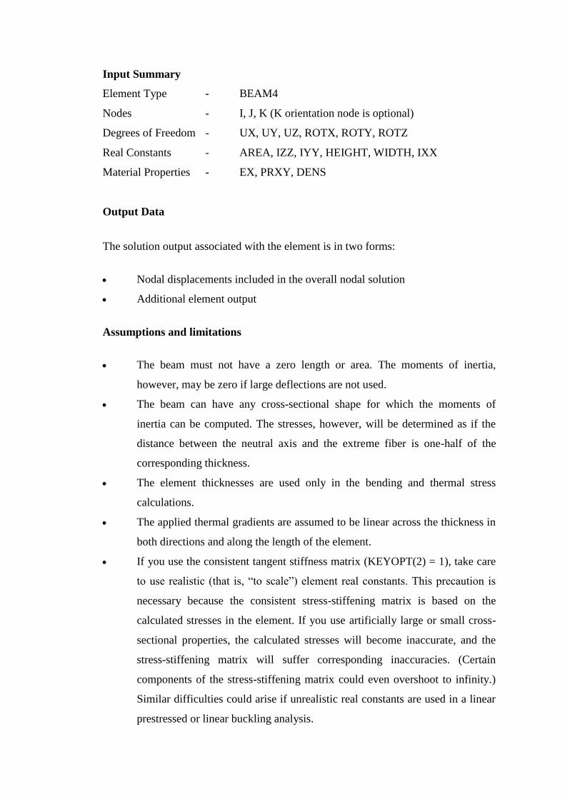
Input Summary
Element Type - BEAM4
Nodes - I, J, K (K orientation node is optional)
Degrees of Freedom - UX, UY, UZ, ROTX, ROTY, ROTZ
Real Constants - AREA, IZZ, IYY, HEIGHT, WIDTH, IXX
Material Properties - EX, PRXY, DENS
Output Data
The solution output associated with the element is in two forms:
Nodal displacements included in the overall nodal solution
Additional element output
Assumptions and limitations
The beam must not have a zero length or area. The moments of inertia,
however, may be zero if large deflections are not used.
The beam can have any cross-sectional shape for which the moments of
inertia can be computed. The stresses, however, will be determined as if the
distance between the neutral axis and the extreme fiber is one-half of the
corresponding thickness.
The element thicknesses are used only in the bending and thermal stress
calculations.
The applied thermal gradients are assumed to be linear across the thickness in
both directions and along the length of the element.
If you use the consistent tangent stiffness matrix (KEYOPT(2) = 1), take care
to use realistic (that is, “to scale”) element real constants. This precaution is
necessary because the consistent stress-stiffening matrix is based on the
calculated stresses in the element. If you use artificially large or small cross-
sectional properties, the calculated stresses will become inaccurate, and the
stress-stiffening matrix will suffer corresponding inaccuracies. (Certain
components of the stress-stiffening matrix could even overshoot to infinity.)
Similar difficulties could arise if unrealistic real constants are used in a linear
prestressed or linear buckling analysis.
Eigenvalues calculated in a gyroscopic modal analysis can be very sensitive to
changes in the initial shift value, leading to potential error in either the real or
imaginary (or both) parts of the eigenvalues.
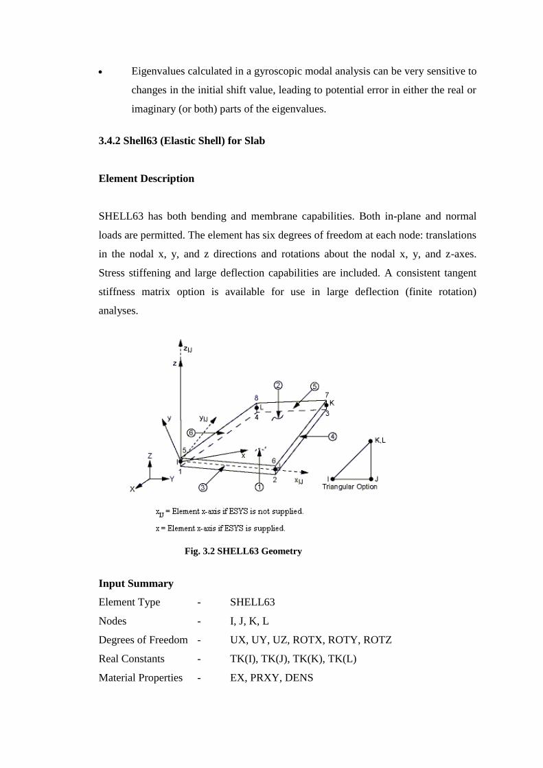
3.4.2 Shell63 (Elastic Shell) for Slab
Element Description
SHELL63 has both bending and membrane capabilities. Both in-plane and normal
loads are permitted. The element has six degrees of freedom at each node: translations
in the nodal x, y, and z directions and rotations about the nodal x, y, and z-axes.
Stress stiffening and large deflection capabilities are included. A consistent tangent
stiffness matrix option is available for use in large deflection (finite rotation)
analyses.
Input Summary
Element Type - SHELL63
Nodes - I, J, K, L
Degrees of Freedom - UX, UY, UZ, ROTX, ROTY, ROTZ
Real Constants - TK(I), TK(J), TK(K), TK(L)
Material Properties - EX, PRXY, DENS
Fig. 3.2 SHELL63 Geometry

Output Data
The solution output associated with the element is in two forms:
Nodal displacements included in the overall nodal solution
Additional element output
Assumptions and Restrictions
Zero area elements are not allowed. This occurs most often whenever the
elements are not numbered properly.
Zero thickness elements or elements tapering down to a zero thickness at any
corner are not allowed.
The applied transverse thermal gradient is assumed to vary linearly through
the thickness and vary bilinearly over the shell surface.
An assemblage of flat shell elements can produce a good approximation of a
curved shell surface provided that each flat element does not extend over more
than a 15° arc. If an elastic foundation stiffness is input, one-fourth of the total
is applied at each node. Shear deflection is not included in this thin-shell
element.
A triangular element may be formed by defining duplicate K and L node
numbers. The extra shapes are automatically deleted for triangular elements so
that the membrane stiffness reduces to a constant strain formulation. For large
deflection analyses, if KEYOPT(1) = 1 (membrane stiffness only), the
element must be triangular.
For KEYOPT(1) = 0 or 2, the four nodes defining the element should lie as
close as possible to a flat plane (for maximum accuracy), but a moderate
amount of warping is permitted. For KEYOPT(1) = 1, the warping limit is
very restrictive. In either case, an excessively warped element may produce a
warning or error message. In the case of warping errors, triangular elements
should be used.
If the lumped mass matrix formulation is specified, the effect of the implied
offsets on the mass matrix is ignored for warped SHELL63 elements.
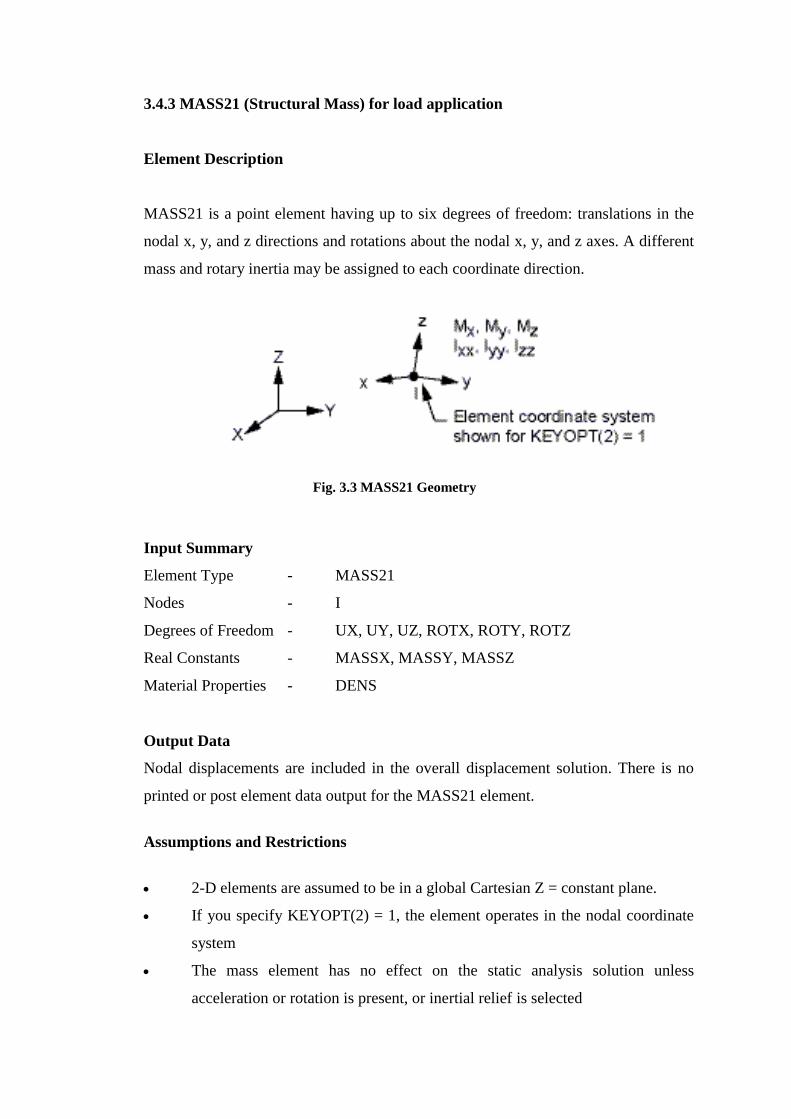
3.4.3 MASS21 (Structural Mass) for load application
Element Description
MASS21 is a point element having up to six degrees of freedom: translations in the
nodal x, y, and z directions and rotations about the nodal x, y, and z axes. A different
mass and rotary inertia may be assigned to each coordinate direction.
Input Summary
Element Type - MASS21
Nodes - I
Degrees of Freedom - UX, UY, UZ, ROTX, ROTY, ROTZ
Real Constants - MASSX, MASSY, MASSZ
Material Properties - DENS
Output Data
Nodal displacements are included in the overall displacement solution. There is no
printed or post element data output for the MASS21 element.
Assumptions and Restrictions
2-D elements are assumed to be in a global Cartesian Z = constant plane.
If you specify KEYOPT(2) = 1, the element operates in the nodal coordinate
system
The mass element has no effect on the static analysis solution unless
acceleration or rotation is present, or inertial relief is selected
Fig. 3.3 MASS21 Geometry

The standard mass summary printout is based on the average of MASSX,
MASSY, and MASSZ if (KEYOPT(3) = 0).
In an inertial relief analysis, the full matrix is used. All terms are used during
the analysis.
3.4.4 LINK8 (3-D Spar or Truss) for diagonal strut
Element Description
LINK8 is a spar which may be used in a variety of engineering applications. This
element can be used to model trusses, sagging cables, links, springs, etc. The 3-D spar
element is a uniaxial tension-compression element with three degrees of freedom at
each node: translations in the nodal x, y, and z directions. As in a pin-jointed
structure, no bending of the element is considered. Plasticity, creep, swelling, stress
stiffening, and large deflection capabilities are included.
Input Summary
Element Type - LINK8
Nodes - I, J
Degrees of Freedom - UX, UY, UZ
Real Constants - AREA
Material Properties - EX, PRXY, DENS
Fig. 3.4 LINK8 Geometry
Output Data
The solution output associated with the element is in two forms:
Nodal displacements included in the overall nodal solution
Additional element output
Assumptions and Restrictions
The spar element assumes a straight bar, axially loaded at its ends, and of
uniform properties from end to end.
The length of the spar must be greater than zero, so nodes I and J must not be
coincident.
The area must be greater than zero.
The temperature is assumed to vary linearly along the length of the spar.
The displacement shape function implies a uniform stress in the spar.
The initial strain is also used in calculating the stress stiffness matrix, if any,
for the first cumulative iteration.
3.4.5 Support Condition
At foundation level all column ends are considered to act under fixed support
condition with all degrees of freedom of the support being restrained.
3.4.6 Load application
The x-z plane is acting as the horizontal plane in global co-ordinate system. The load
cases considered according to BNBC, 1993.
The considered load can be categorized to vertical and lateral directions.
Vertical load
Dead Load: Weight of permanent structural and nonstructural component of the
structure is considered as dead load. The structural self weight is already taken with
the modeling and the rest nonstructural vertical load is applied as mass for floor finish
(1.437 2310
mmN ) and partition wall (Infill) on nodes as uniformly distributed
load.
Live Load: The temporary load acting on structure as occupancy load is called live
load and considered as uniformly distributed surface load (valuing 2.395
2310
mmN ) in vertical direction.
Lateral Load
Earthquake Load: The earthquake load acts at lateral direction. Here, this seismic
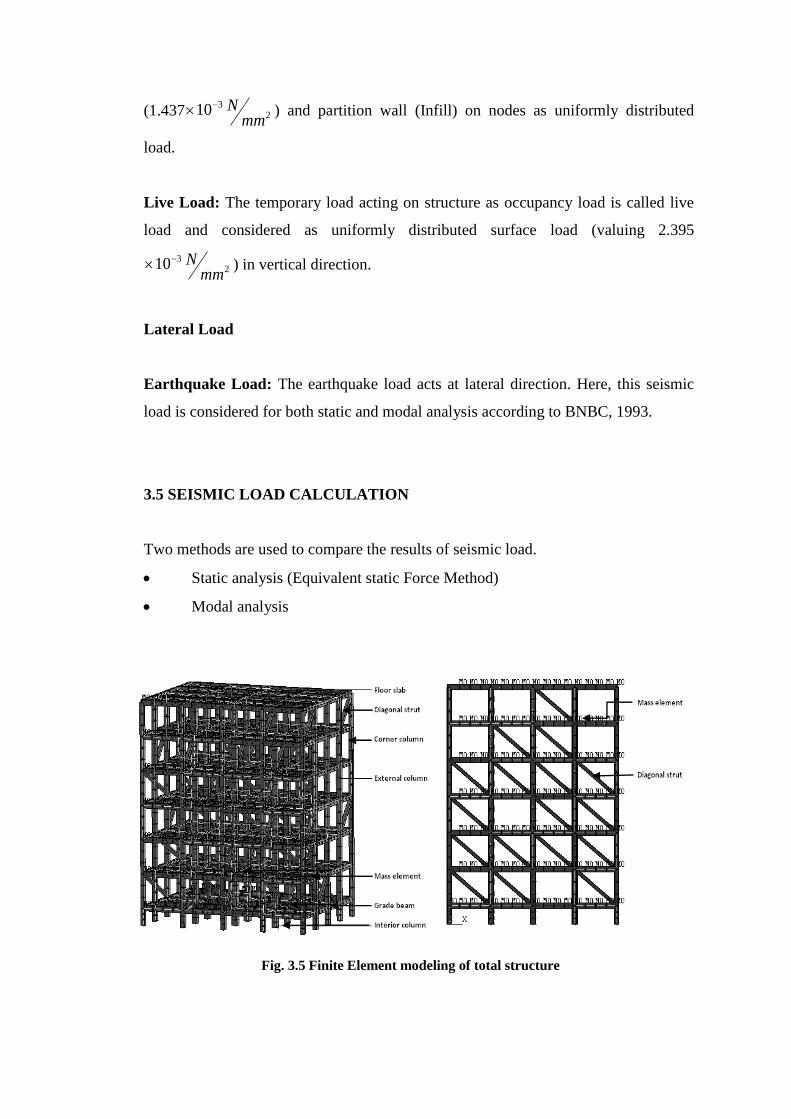
load is considered for both static and modal analysis according to BNBC, 1993.
3.5 SEISMIC LOAD CALCULATION
Two methods are used to compare the results of seismic load.
Static analysis (Equivalent static Force Method)
Modal analysis
Fig. 3.5 Finite Element modeling of total structure

3.5.1 Static Analysis (Equivalent static Force Method)
According to BNBC, 1993 empirical equations are given in this method is applied for
calculation of seismic base shear based on vibration period of whole structure. No
consideration for structural nonlinearity and stiffness is made here and the considered
period is for first mode of vibration only.
Design Base Shear, WR
ZICV 3.1
Where,
Z = Seismic zone co-efficient
I = Structural importance coefficient
W = Total seismic dead load
R = Response modification factor for structural system
C = 3
2
25.1
T
S 3.2
S = Sight co-efficient for soil characteristics
T = Fundamental period of vibration
= 43
n )h(073.0 3.3
hn = Height of structure above base (in meter)
3.5.2 Modal Analysis
Modal analysis is helpful to determine the critical vibration characteristics of
structure. The natural frequency and mode shape is important to determine the design
forces of structure under dynamic loading condition and modal analysis is used to do
that.
Response Spectrum Method (RSM)
In this method of dynamic analysis the multiple modes of response of a structure are
taken into account. It’s a plot of the peak or the steady-state response of a series of
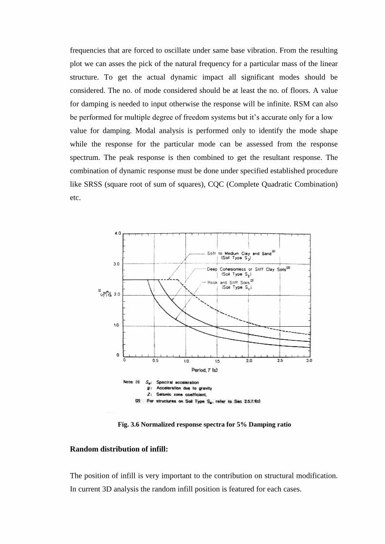
frequencies that are forced to oscillate under same base vibration. From the resulting
plot we can asses the pick of the natural frequency for a particular mass of the linear
structure. To get the actual dynamic impact all significant modes should be
considered. The no. of mode considered should be at least the no. of floors. A value
for damping is needed to input otherwise the response will be infinite. RSM can also
be performed for multiple degree of freedom systems but it’s accurate only for a low
value for damping. Modal analysis is performed only to identify the mode shape
while the response for the particular mode can be assessed from the response
spectrum. The peak response is then combined to get the resultant response. The
combination of dynamic response must be done under specified established procedure
like SRSS (square root of sum of squares), CQC (Complete Quadratic Combination)
etc.
Random distribution of infill:
The position of infill is very important to the contribution on structural modification.
In current 3D analysis the random infill position is featured for each cases.
Fig. 3.6 Normalized response spectra for 5% Damping ratio
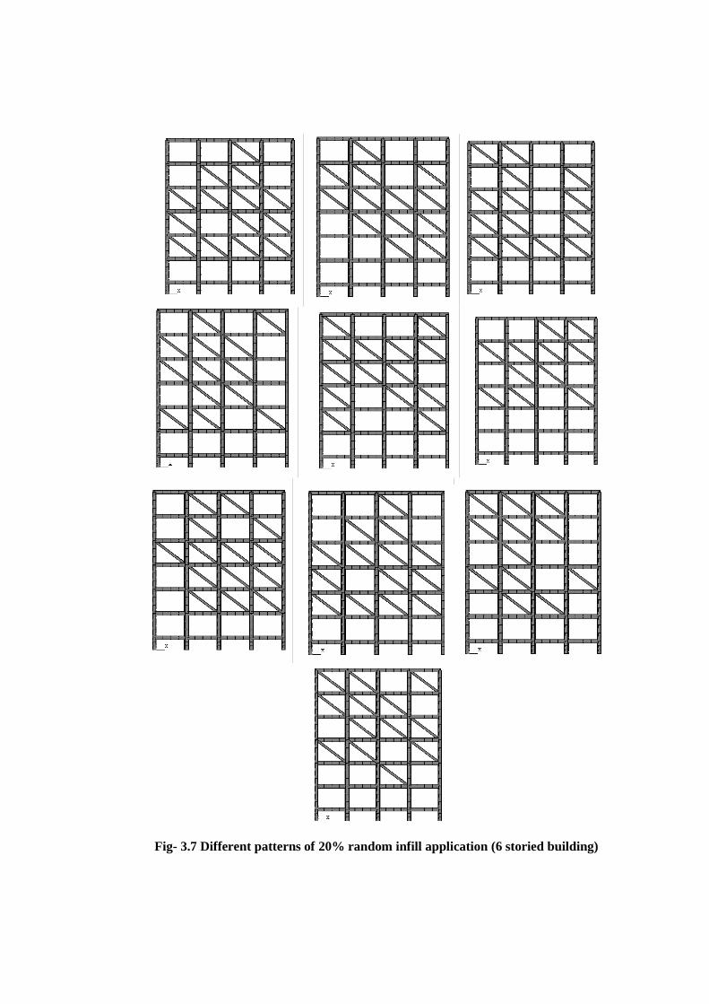
Fig- 3.7 Different patterns of 20% random infill application (6 storied building)
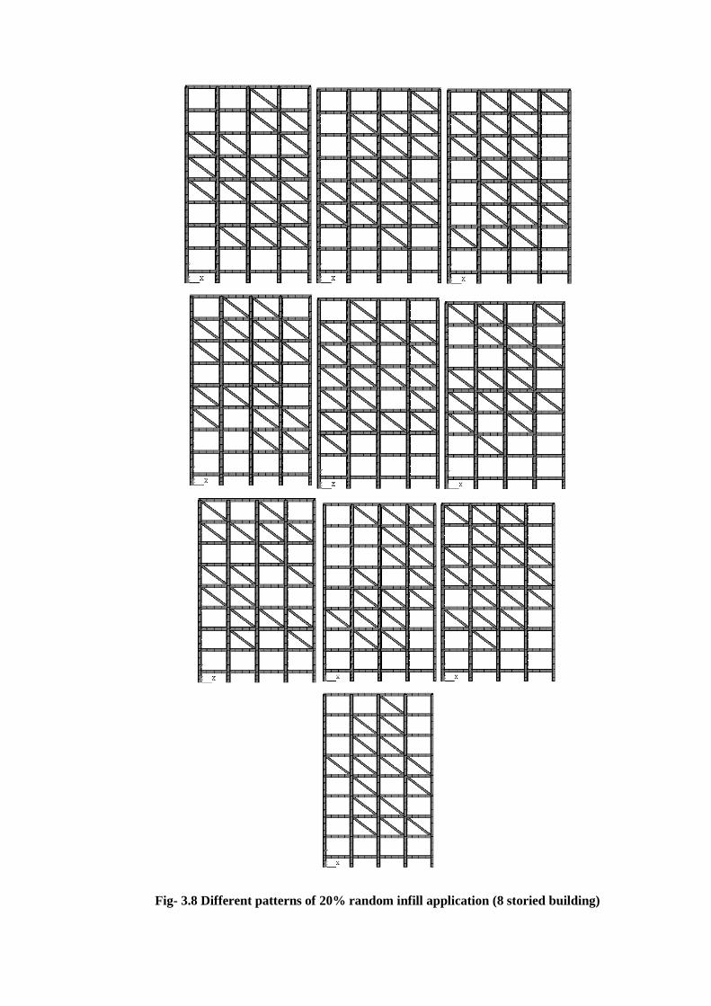
Fig- 3.8 Different patterns of 20% random infill application (8 storied building)
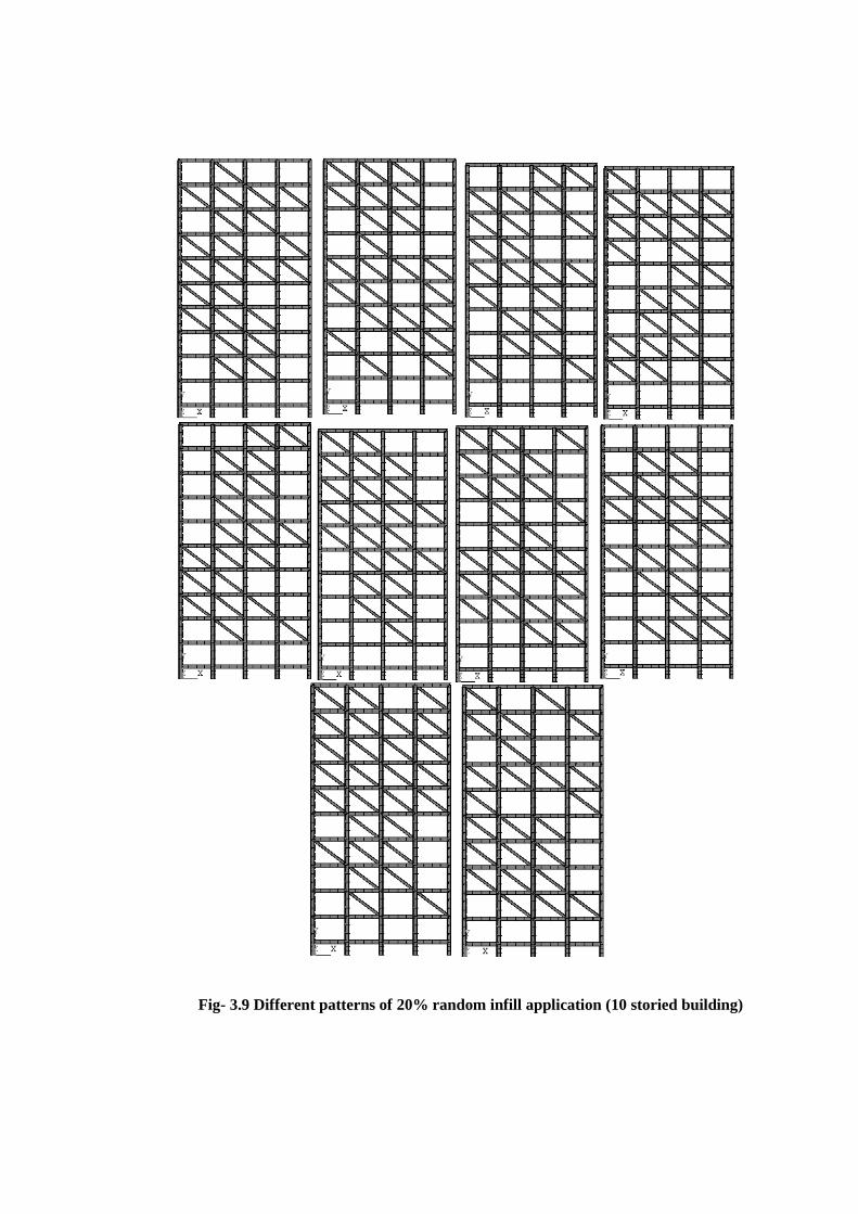
Fig- 3.9 Different patterns of 20% random infill application (10 storied building)
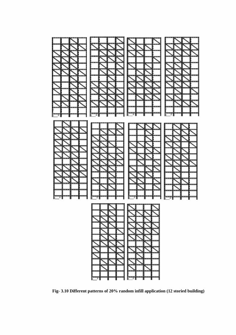
Fig- 3.10 Different patterns of 20% random infill application (12 storied building)
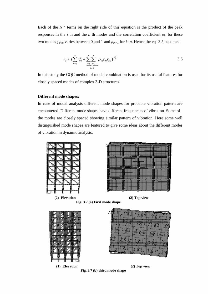
Methods of modal combination:
SRSS meaning Square root of the Sum of the Squares is a very common approach of
modal combination. It’s done on the maximum modal values in order to estimate the
values of displacement or forces. The SRSS rule for modal combination was
developed by E. Rosenblueth’s in his PhD thesis (1951).
)(1
2
00
N
n
nrr 3.4
The peak response in each mode is squared, the squared modal peaks are summed and
the square root of the sum provides an estimation of the peak total response.
This modal combination rule provides excellent response estimates for structures with
well separated natural frequencies. This limitation has not always been recognized in
applying this rule to practical problems and at times it has been misapplied to systems
with closely spaced natural frequencies such as piping systems in nuclear power
plants and multistory buildings with unsymmetric plan. For three dimensional
structures, in which a large number of frequencies are almost identical, this
assumption is not justified.
Another method is CQC meaning Complete Quadratic Combination for modal
combination. It’s a more modern method over SRSS as it has overcome the limitation
of SRSS. This method was first applied by Wilson, Kiureghian and Bayo, 1981 is
applicable to a wider class of structures. It’s based on random vibration theories with
wide acceptance to most engineers and has been incorporated as an option in most
modern computer programs for seismic analysis. The peak value of a typical force
can now be estimated, from the maximum modal values by the CQC method with the
application of the following double summation equation.
21
1 1
000 )(
N
i
N
n
niin rrr 3.5
Each of the N 2 terms on the right side of this equation is the product of the peak
responses in the i th and the n th modes and the correlation coefficient ρin for these
two modes ; ρin varies between 0 and 1 and ρin=1 for i=n. Hence the eqn 3.5 becomes
21
1
00
1 1
2
00 )(
N
n
niin
ni
N
i
N
n
n rrrr
3.6
In this study the CQC method of modal combination is used for its useful features for
closely spaced modes of complex 3-D structures.
Different mode shapes:
In case of modal analysis different mode shapes for probable vibration pattern are
encountered. Different mode shapes have different frequencies of vibration. Some of
the modes are closely spaced showing similar pattern of vibration. Here some well
distinguished mode shapes are featured to give some ideas about the different modes
of vibration in dynamic analysis.
(2) Elevation (2) Top view
Fig. 3.7 (a) First mode shape
(1) Elevation (2) Top view
Fig. 3.7 (b) third mode shape
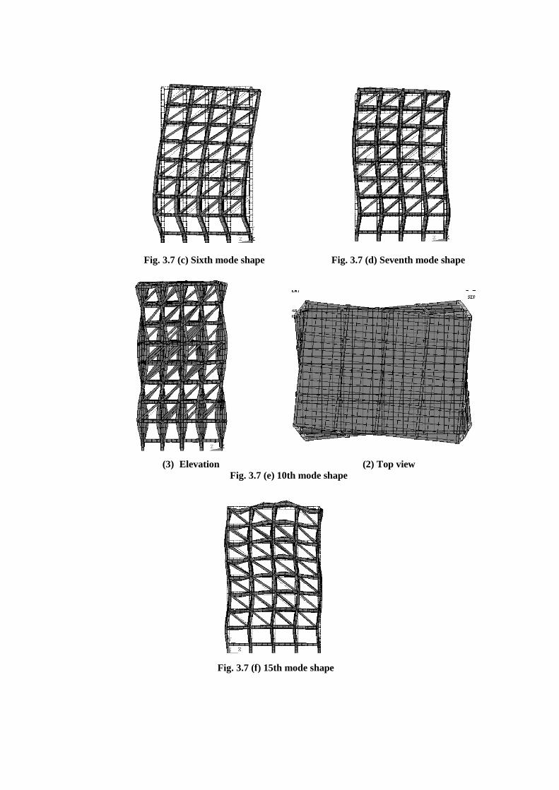
Fig. 3.7 (f) 15th mode shape
Fig. 3.7 (c) Sixth mode shape Fig. 3.7 (d) Seventh mode shape
(3) Elevation (2) Top view
Fig. 3.7 (e) 10th mode shape
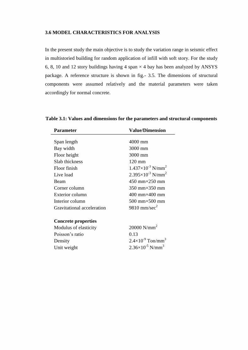
3.6 MODEL CHARACTERISTICS FOR ANALYSIS
In the present study the main objective is to study the variation range in seismic effect
in multistoried building for random application of infill with soft story. For the study
6, 8, 10 and 12 story buildings having 4 span × 4 bay has been analyzed by ANSYS
package. A reference structure is shown in fig.- 3.5. The dimensions of structural
components were assumed relatively and the material parameters were taken
accordingly for normal concrete.
Table 3.1: Values and dimensions for the parameters and structural components
Parameter Value/Dimension
Span length 4000 mm
Bay width 3000 mm
Floor height 3000 mm
Slab thickness 120 mm
Floor finish 1.437×10⁻³
N/mm2
Live load 2.395×10⁻³
N/mm2
Beam 450 mm×250 mm
Corner column 350 mm×350 mm
Exterior column 400 mm×400 mm
Interior column 500 mm×500 mm
Gravitational acceleration 9810 mm/sec2
Concrete properties
Modulus of elasticity 20000 N/mm2
Poisson’s ratio 0.13
Density 2.4×10⁻⁹
Ton/mm3
Unit weight 2.36×10⁻⁵
N/mm3
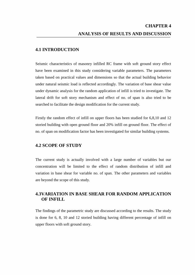
CHAPTER 4
ANALYSIS OF RESULTS AND DISCUSSION
4.1 INTRODUCTION
Seismic characteristics of masonry infilled RC frame with soft ground story effect
have been examined in this study considering variable parameters. The parameters
taken based on practical values and dimensions so that the actual building behavior
under natural seismic load is reflected accordingly. The variation of base shear value
under dynamic analysis for the random application of infill is tried to investigate. The
lateral drift for soft story mechanism and effect of no. of span is also tried to be
searched to facilitate the design modification for the current study.
Firstly the random effect of infill on upper floors has been studied for 6,8,10 and 12
storied building with open ground floor and 20% infill on ground floor. The effect of
no. of span on modification factor has been investigated for similar building systems.
4.2 SCOPE OF STUDY
The current study is actually involved with a large number of variables but our
concentration will be limited to the effect of random distribution of infill and
variation in base shear for variable no. of span. The other parameters and variables
are beyond the scope of this study.
4.3VARIATION IN BASE SHEAR FOR RANDOM APPLICATION
OF INFILL
The findings of the parametric study are discussed according to the results. The study
is done for 6, 8, 10 and 12 storied building having different percentage of infill on
upper floors with soft ground story.

4.3.1 Range of variation in base shear value
The results obtained from the analysis of finite element model of MI-RC frame are
tabulated sequentially and shown graphically.
From the results obtained (table-4.1 to table-4.12 and fig-4.1 to fig-4.32) we find that
for a particular frame the effect of randomly applied infill is not the same on base
shear value. Under each parameter the RSM analysis is done for 10 times and the
variation in result is observed. The bar charts show that for infill percentage less than
50% (20% and 40%) the base shear value has a wider range of variation while for
infill percentage greater than 50% (60% and 80%) the range of variation is narrower.
This is because for less % of infill the opportunity of variation in infill location and
pattern is far higher while for high % of infill the opportunity of variation in infill
location and pattern is less.
It is observed that for higher % of infill application the standard deviation of base
shear value by RSM is not of large value. So we can use individual value of base
shear for random effect with certain reliability. But in case of infill % less than 50%
we must take an average of close values neglecting the highly deviated ones.
4.3.2 Modification factor for different parameters
To find the modification factor for randomly applied infill at different percentage, the
average values have been used. Here two sets of ground floor condition with different
% of infill on upper floors for 6, 8, 10 and 12 storied buildings have been analyzed.
From the previous results we have some correlations for modification factor for
application of different percentage of infill. The factor increases with increase of no.
of floors.
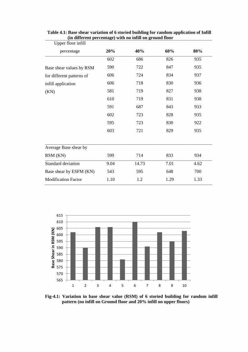
Table 4.1: Base shear variation of 6 storied building for random application of Infill
(in different percentage) with no infill on ground floor Upper floor infill
percentage 20% 40% 60% 80%
Base shear values by RSM
for different patterns of
infill application
(KN)
602 686 826 935
590 722 847 935
606 724 834 937
606 718 830 936
581 719 827 938
610 719 831 938
591 687 843 933
602 723 828 935
595 723 830 922
603 721 829 935
Average Base shear by
RSM (KN) 599 714 833 934
Standard deviation 9.04 14.73 7.01 4.62
Base shear by ESFM (KN) 543 595 648 700
Modification Factor 1.10 1.2 1.29 1.33
Fig-4.1: Variation in base shear value (RSM) of 6 storied building for random infill
pattern (no infill on Ground floor and 20% infill on upper floors)
565
570
575
580
585
590
595
600
605
610
615
1 2 3 4 5 6 7 8 9 10
Bas
e S
he
ar in
RSM
(K
N)
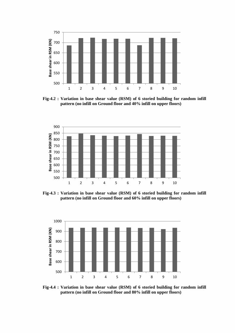
Fig-4.2 : Variation in base shear value (RSM) of 6 storied building for random infill
pattern (no infill on Ground floor and 40% infill on upper floors)
Fig-4.3 : Variation in base shear value (RSM) of 6 storied building for random infill
pattern (no infill on Ground floor and 60% infill on upper floors)
Fig-4.4 : Variation in base shear value (RSM) of 6 storied building for random infill
pattern (no infill on Ground floor and 80% infill on upper floors)
500
550
600
650
700
750
1 2 3 4 5 6 7 8 9 10
Bas
e s
he
ar in
RSM
(K
N)
500
550
600
650
700
750
800
850
900
1 2 3 4 5 6 7 8 9 10
Bas
e s
he
ar in
RSM
(K
N)
500
600
700
800
900
1000
1 2 3 4 5 6 7 8 9 10
Bas
e s
he
ar in
RSM
(K
N)

Table 4.2: Base shear variation of 6 storied building for random application of
Infill (in different percentage) with 20% infill on ground floor Upper floor infill
percentage 20% 40% 60% 80%
Base shear values by RSM
for different patterns of
infill application
(KN)
526 631 802 901
578 678 819 888
582 641 791 906
582 668 807 867
526 642 765 874
578 646 777 877
582 596 798 871
555 644 809 885
578 656 773 896
582 653 813 898
Average Base shear by
RSM (KN) 567 646 795 886
Standard deviation 23.01 22.17 18.31 13.67
Base shear by ESFM (KN) 551 603 655 708
Modification Factor 1.03 1.07 1.21 1.25
Fig-4.5 : Variation in base shear value (RSM) of 6 storied building for random infill
pattern (20% infill on Ground floor and 20% infill on upper floors)
500
510
520
530
540
550
560
570
580
590
1 2 3 4 5 6 7 8 9 10
Bas
e s
he
ar in
RSM
(K
N)

Fig-4.6 : Variation in base shear value (RSM) of 6 storied building for random infill
pattern (20% infill on Ground floor and 40% infill on upper floors)
Fig-4.7 : Variation in base shear value (RSM) of 6 storied building for random infill
pattern (20% infill on Ground floor and 60% infill on upper floors)
Fig-4.8 : Variation in base shear value (RSM) of 6 storied building for random infill
pattern (20% infill on Ground floor and 80% infill on upper floors)
500
520
540
560
580
600
620
640
660
680
700
1 2 3 4 5 6 7 8 9 10
Bas
e s
he
ar in
RSM
(K
N)
500
550
600
650
700
750
800
850
1 2 3 4 5 6 7 8 9 10
Bas
e s
he
ar in
RSM
(K
N)
500
550
600
650
700
750
800
850
900
950
1 2 3 4 5 6 7 8 9 10
Bas
e s
he
ar in
RSM
(K
N)
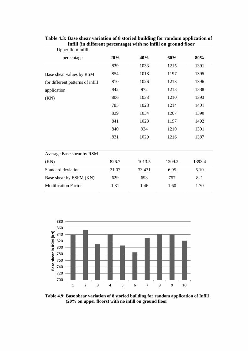
Table 4.3: Base shear variation of 8 storied building for random application of
Infill (in different percentage) with no infill on ground floor Upper floor infill
percentage 20% 40% 60% 80%
Base shear values by RSM
for different patterns of infill
application
(KN)
839 1033 1215 1391
854 1018 1197 1395
810 1026 1213 1396
842 972 1213 1388
806 1033 1210 1393
785 1028 1214 1401
829 1034 1207 1390
841 1028 1197 1402
840 934 1210 1391
821 1029 1216 1387
Average Base shear by RSM
(KN) 826.7 1013.5 1209.2 1393.4
Standard deviation 21.07 33.431 6.95 5.10
Base shear by ESFM (KN) 629 693 757 821
Modification Factor 1.31 1.46 1.60 1.70
Table 4.9: Base shear variation of 8 storied building for random application of Infill
(20% on upper floors) with no infill on ground floor
700
720
740
760
780
800
820
840
860
880
1 2 3 4 5 6 7 8 9 10
Bas
e s
he
ar in
RSM
(K
N)
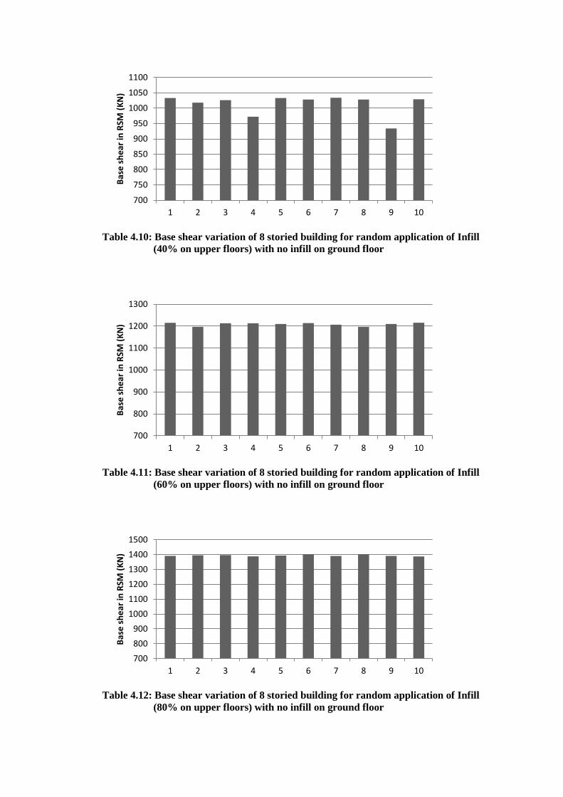
Table 4.10: Base shear variation of 8 storied building for random application of Infill
(40% on upper floors) with no infill on ground floor
Table 4.11: Base shear variation of 8 storied building for random application of Infill
(60% on upper floors) with no infill on ground floor
Table 4.12: Base shear variation of 8 storied building for random application of Infill
(80% on upper floors) with no infill on ground floor
700
750
800
850
900
950
1000
1050
1100
1 2 3 4 5 6 7 8 9 10
Bas
e s
he
ar in
RSM
(K
N)
700
800
900
1000
1100
1200
1300
1 2 3 4 5 6 7 8 9 10
Bas
e s
he
ar in
RSM
(K
N)
700
800
900
1000
1100
1200
1300
1400
1500
1 2 3 4 5 6 7 8 9 10
Bas
e s
he
ar in
RSM
(K
N)
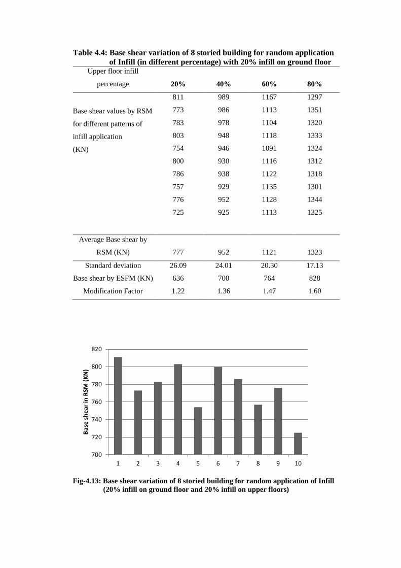
Table 4.4: Base shear variation of 8 storied building for random application
of Infill (in different percentage) with 20% infill on ground floor Upper floor infill
percentage 20% 40% 60% 80%
Base shear values by RSM
for different patterns of
infill application
(KN)
811 989 1167 1297
773 986 1113 1351
783 978 1104 1320
803 948 1118 1333
754 946 1091 1324
800 930 1116 1312
786 938 1122 1318
757 929 1135 1301
776 952 1128 1344
725 925 1113 1325
Average Base shear by
RSM (KN) 777 952 1121 1323
Standard deviation 26.09 24.01 20.30 17.13
Base shear by ESFM (KN) 636 700 764 828
Modification Factor 1.22 1.36 1.47 1.60
Fig-4.13: Base shear variation of 8 storied building for random application of Infill
(20% infill on ground floor and 20% infill on upper floors)
700
720
740
760
780
800
820
1 2 3 4 5 6 7 8 9 10
Bas
e s
he
ar in
RSM
(K
N)
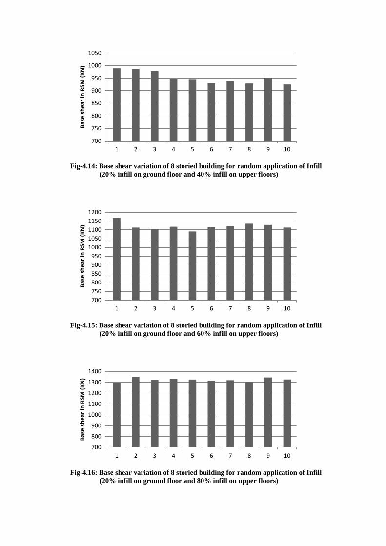
Fig-4.14: Base shear variation of 8 storied building for random application of Infill
(20% infill on ground floor and 40% infill on upper floors)
Fig-4.15: Base shear variation of 8 storied building for random application of Infill
(20% infill on ground floor and 60% infill on upper floors)
Fig-4.16: Base shear variation of 8 storied building for random application of Infill
(20% infill on ground floor and 80% infill on upper floors)
700
750
800
850
900
950
1000
1050
1 2 3 4 5 6 7 8 9 10
Bas
e s
he
ar in
RSM
(K
N)
700
750
800
850
900
950
1000
1050
1100
1150
1200
1 2 3 4 5 6 7 8 9 10
Bas
e s
he
ar in
RSM
(K
N)
700
800
900
1000
1100
1200
1300
1400
1 2 3 4 5 6 7 8 9 10
Bas
e s
he
ar in
RSM
(K
N)
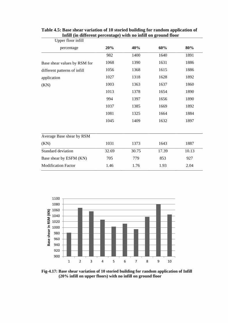
Table 4.5: Base shear variation of 10 storied building for random application of
Infill (in different percentage) with no infill on ground floor Upper floor infill
percentage 20% 40% 60% 80%
Base shear values by RSM for
different patterns of infill
application
(KN)
982 1400 1640 1891
1068 1390 1631 1886
1056 1368 1615 1886
1027 1318 1628 1892
1003 1363 1637 1860
1013 1378 1654 1890
994 1397 1656 1890
1037 1385 1669 1892
1081 1325 1664 1884
1045 1409 1632 1897
Average Base shear by RSM
(KN) 1031 1373 1643 1887
Standard deviation 32.69 30.75 17.39 10.13
Base shear by ESFM (KN) 705 779 853 927
Modification Factor 1.46 1.76 1.93 2.04
Fig-4.17: Base shear variation of 10 storied building for random application of Infill
(20% infill on upper floors) with no infill on ground floor
900
920
940
960
980
1000
1020
1040
1060
1080
1100
1 2 3 4 5 6 7 8 9 10
Bas
e s
he
ar in
RSM
(K
N)
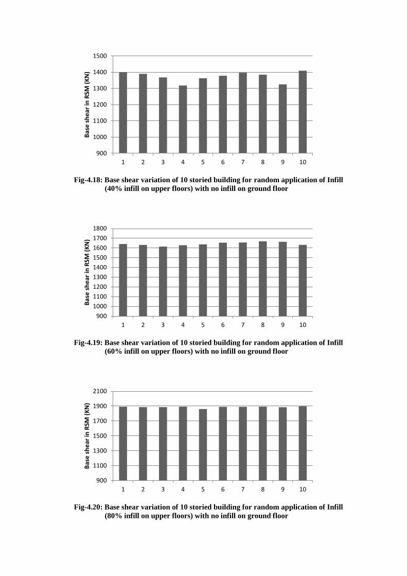
Fig-4.18: Base shear variation of 10 storied building for random application of Infill
(40% infill on upper floors) with no infill on ground floor
Fig-4.19: Base shear variation of 10 storied building for random application of Infill
(60% infill on upper floors) with no infill on ground floor
Fig-4.20: Base shear variation of 10 storied building for random application of Infill
(80% infill on upper floors) with no infill on ground floor
900
1000
1100
1200
1300
1400
1500
1 2 3 4 5 6 7 8 9 10
Bas
e s
he
ar in
RSM
(K
N)
900
1000
1100
1200
1300
1400
1500
1600
1700
1800
1 2 3 4 5 6 7 8 9 10
Bas
e s
he
ar in
RSM
(K
N)
900
1100
1300
1500
1700
1900
2100
1 2 3 4 5 6 7 8 9 10
Bas
e s
he
ar in
RSM
(K
N)
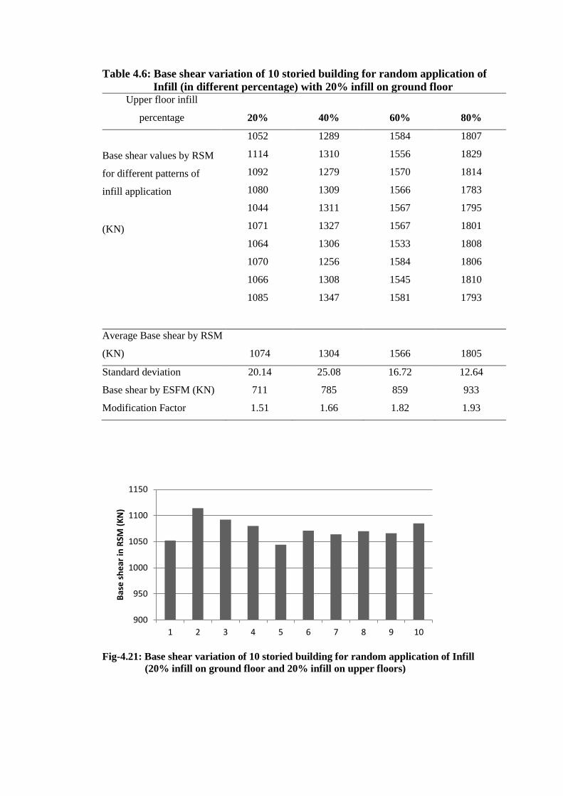
Table 4.6: Base shear variation of 10 storied building for random application of
Infill (in different percentage) with 20% infill on ground floor Upper floor infill
percentage 20% 40% 60% 80%
Base shear values by RSM
for different patterns of
infill application
(KN)
1052 1289 1584 1807
1114 1310 1556 1829
1092 1279 1570 1814
1080 1309 1566 1783
1044 1311 1567 1795
1071 1327 1567 1801
1064 1306 1533 1808
1070 1256 1584 1806
1066 1308 1545 1810
1085 1347 1581 1793
Average Base shear by RSM
(KN) 1074 1304 1566 1805
Standard deviation 20.14 25.08 16.72 12.64
Base shear by ESFM (KN) 711 785 859 933
Modification Factor 1.51 1.66 1.82 1.93
Fig-4.21: Base shear variation of 10 storied building for random application of Infill
(20% infill on ground floor and 20% infill on upper floors)
900
950
1000
1050
1100
1150
1 2 3 4 5 6 7 8 9 10
Bas
e s
he
ar in
RSM
(K
N)
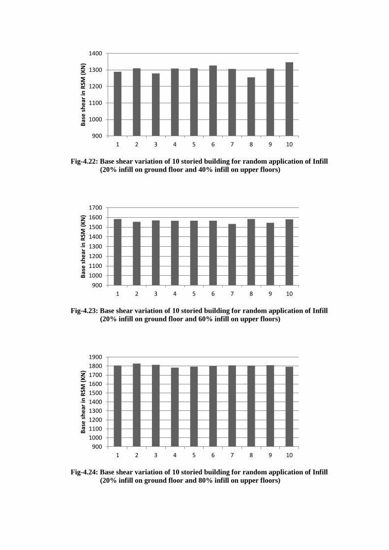
Fig-4.22: Base shear variation of 10 storied building for random application of Infill
(20% infill on ground floor and 40% infill on upper floors)
Fig-4.23: Base shear variation of 10 storied building for random application of Infill
(20% infill on ground floor and 60% infill on upper floors)
Fig-4.24: Base shear variation of 10 storied building for random application of Infill
(20% infill on ground floor and 80% infill on upper floors)
900
1000
1100
1200
1300
1400
1 2 3 4 5 6 7 8 9 10
Bas
e s
he
ar in
RSM
(K
N)
900
1000
1100
1200
1300
1400
1500
1600
1700
1 2 3 4 5 6 7 8 9 10
Bas
e s
he
ar in
RSM
(K
N)
900
1000
1100
1200
1300
1400
1500
1600
1700
1800
1900
1 2 3 4 5 6 7 8 9 10
Bas
e s
he
ar in
RSM
(K
N)
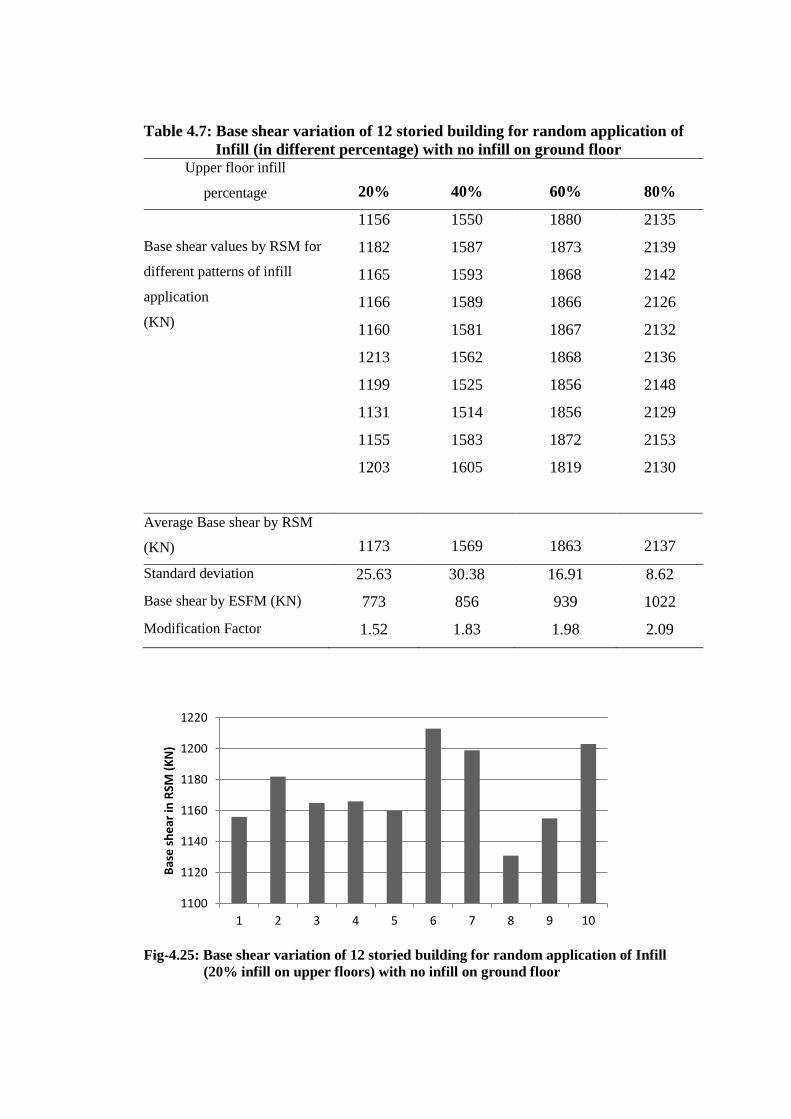
Table 4.7: Base shear variation of 12 storied building for random application of
Infill (in different percentage) with no infill on ground floor Upper floor infill
percentage 20% 40% 60% 80%
Base shear values by RSM for
different patterns of infill
application
(KN)
1156 1550 1880 2135
1182 1587 1873 2139
1165 1593 1868 2142
1166 1589 1866 2126
1160 1581 1867 2132
1213 1562 1868 2136
1199 1525 1856 2148
1131 1514 1856 2129
1155 1583 1872 2153
1203 1605 1819 2130
Average Base shear by RSM
(KN) 1173 1569 1863 2137
Standard deviation 25.63 30.38 16.91 8.62
Base shear by ESFM (KN) 773 856 939 1022
Modification Factor 1.52 1.83 1.98 2.09
Fig-4.25: Base shear variation of 12 storied building for random application of Infill
(20% infill on upper floors) with no infill on ground floor
1100
1120
1140
1160
1180
1200
1220
1 2 3 4 5 6 7 8 9 10
Bas
e s
he
ar in
RSM
(K
N)
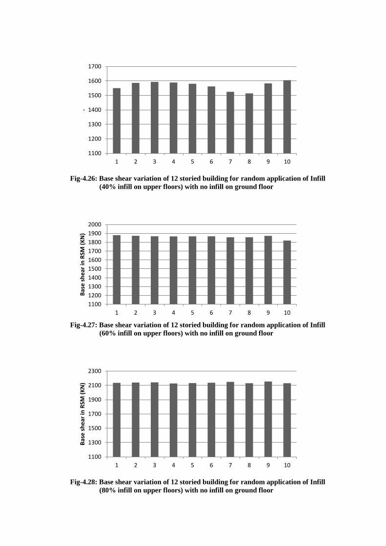
Fig-4.26: Base shear variation of 12 storied building for random application of Infill
(40% infill on upper floors) with no infill on ground floor
Fig-4.27: Base shear variation of 12 storied building for random application of Infill
(60% infill on upper floors) with no infill on ground floor
Fig-4.28: Base shear variation of 12 storied building for random application of Infill
(80% infill on upper floors) with no infill on ground floor
1100
1200
1300
1400
1500
1600
1700
1 2 3 4 5 6 7 8 9 10
.
1100
1200
1300
1400
1500
1600
1700
1800
1900
2000
1 2 3 4 5 6 7 8 9 10
Bas
e s
he
ar in
RSM
(K
N)
1100
1300
1500
1700
1900
2100
2300
1 2 3 4 5 6 7 8 9 10
Bas
e s
he
ar in
RSM
(K
N)
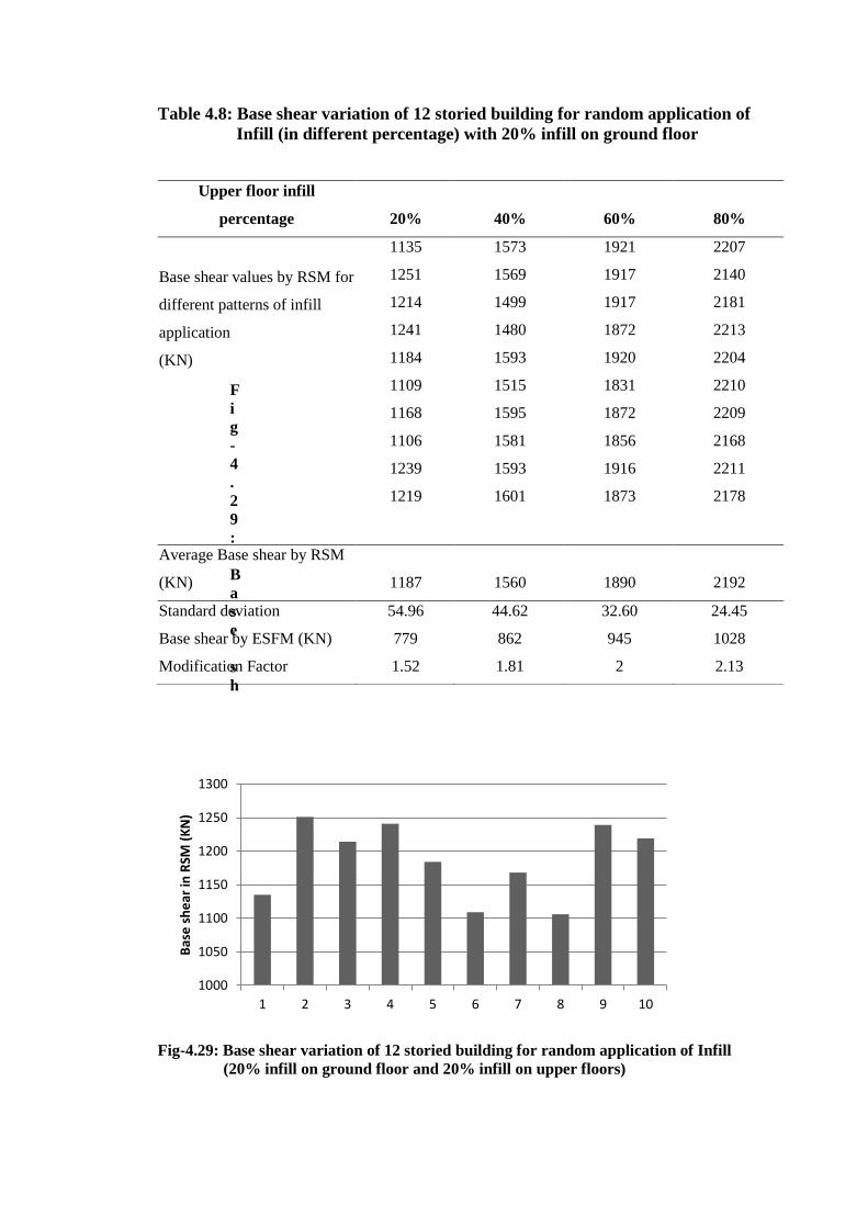
Table 4.8: Base shear variation of 12 storied building for random application of
Infill (in different percentage) with 20% infill on ground floor
F
i
g
-
4
.
2
9
:
B
a
s
e
s
h
Fig-4.29: Base shear variation of 12 storied building for random application of Infill
(20% infill on ground floor and 20% infill on upper floors)
Upper floor infill
percentage 20% 40% 60% 80%
Base shear values by RSM for
different patterns of infill
application
(KN)
1135 1573 1921 2207
1251 1569 1917 2140
1214 1499 1917 2181
1241 1480 1872 2213
1184 1593 1920 2204
1109 1515 1831 2210
1168 1595 1872 2209
1106 1581 1856 2168
1239 1593 1916 2211
1219 1601 1873 2178
Average Base shear by RSM
(KN) 1187 1560 1890 2192
Standard deviation 54.96 44.62 32.60 24.45
Base shear by ESFM (KN) 779 862 945 1028
Modification Factor 1.52 1.81 2 2.13
1000
1050
1100
1150
1200
1250
1300
1 2 3 4 5 6 7 8 9 10
Bas
e s
he
ar in
RSM
(K
N)
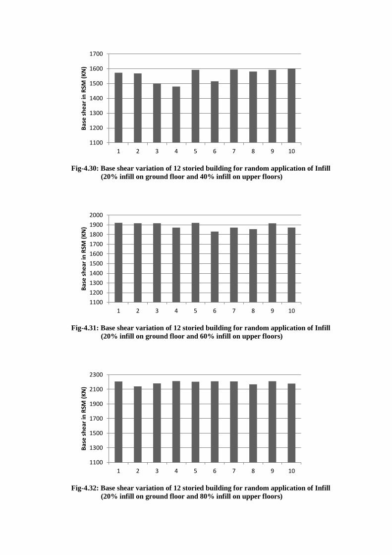
Fig-4.30: Base shear variation of 12 storied building for random application of Infill
(20% infill on ground floor and 40% infill on upper floors)
Fig-4.31: Base shear variation of 12 storied building for random application of Infill
(20% infill on ground floor and 60% infill on upper floors)
Fig-4.32: Base shear variation of 12 storied building for random application of Infill
(20% infill on ground floor and 80% infill on upper floors)
1100
1200
1300
1400
1500
1600
1700
1 2 3 4 5 6 7 8 9 10
Bas
e s
he
ar in
RSM
(K
N)
1100
1200
1300
1400
1500
1600
1700
1800
1900
2000
1 2 3 4 5 6 7 8 9 10
Bas
e s
he
ar in
RSM
(K
N)
1100
1300
1500
1700
1900
2100
2300
1 2 3 4 5 6 7 8 9 10
Bas
e s
he
ar in
RSM
(K
N)
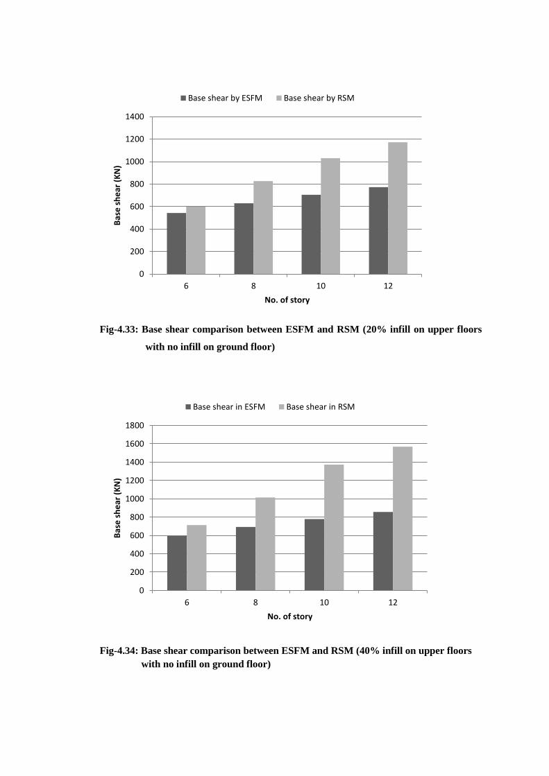
Fig-4.33: Base shear comparison between ESFM and RSM (20% infill on upper floors
with no infill on ground floor)
Fig-4.34: Base shear comparison between ESFM and RSM (40% infill on upper floors
with no infill on ground floor)
0
200
400
600
800
1000
1200
1400
6 8 10 12
Bas
e s
he
ar (
KN
)
No. of story
Base shear by ESFM Base shear by RSM
0
200
400
600
800
1000
1200
1400
1600
1800
6 8 10 12
Bas
e s
he
ar (
KN
)
No. of story
Base shear in ESFM Base shear in RSM
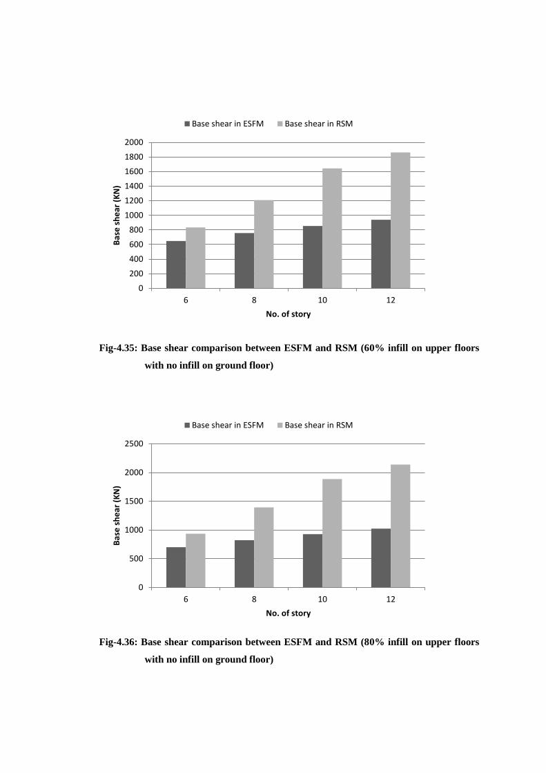
Fig-4.35: Base shear comparison between ESFM and RSM (60% infill on upper floors
with no infill on ground floor)
Fig-4.36: Base shear comparison between ESFM and RSM (80% infill on upper floors
with no infill on ground floor)
0
200
400
600
800
1000
1200
1400
1600
1800
2000
6 8 10 12
Bas
e s
he
ar (
KN
)
No. of story
Base shear in ESFM Base shear in RSM
0
500
1000
1500
2000
2500
6 8 10 12
Bas
e s
he
ar (
KN
)
No. of story
Base shear in ESFM Base shear in RSM
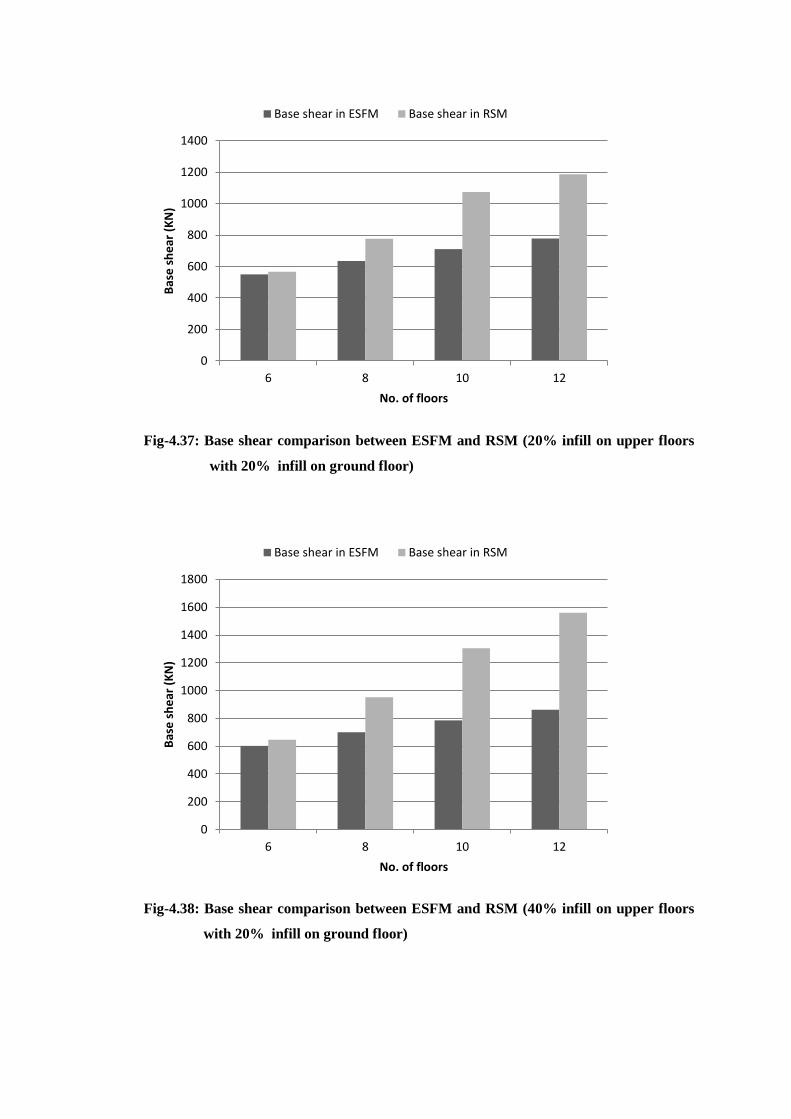
Fig-4.37: Base shear comparison between ESFM and RSM (20% infill on upper floors
with 20% infill on ground floor)
Fig-4.38: Base shear comparison between ESFM and RSM (40% infill on upper floors
with 20% infill on ground floor)
0
200
400
600
800
1000
1200
1400
6 8 10 12
Bas
e s
he
ar (
KN
)
No. of floors
Base shear in ESFM Base shear in RSM
0
200
400
600
800
1000
1200
1400
1600
1800
6 8 10 12
Bas
e s
he
ar (
KN
)
No. of floors
Base shear in ESFM Base shear in RSM
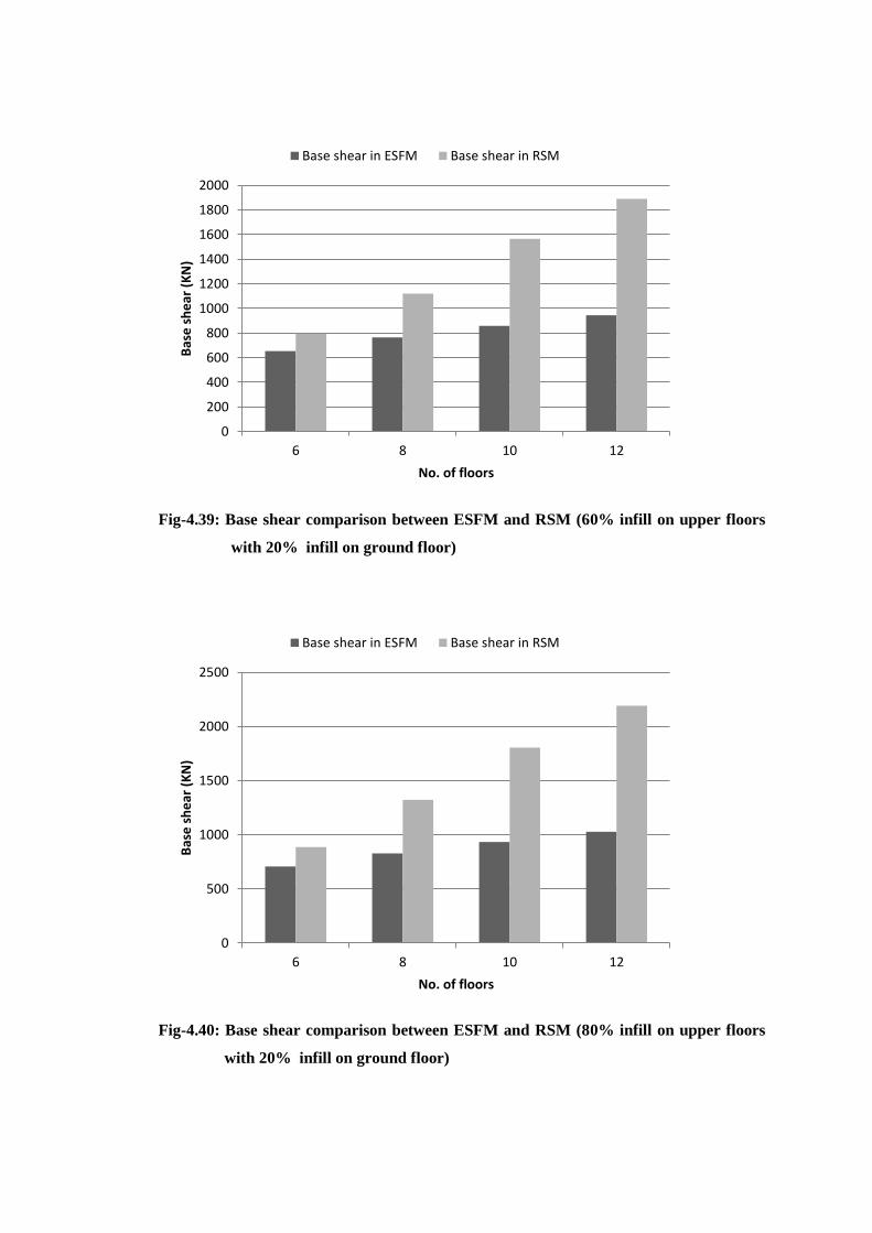
Fig-4.39: Base shear comparison between ESFM and RSM (60% infill on upper floors
with 20% infill on ground floor)
Fig-4.40: Base shear comparison between ESFM and RSM (80% infill on upper floors
with 20% infill on ground floor)
0
200
400
600
800
1000
1200
1400
1600
1800
2000
6 8 10 12
Bas
e s
he
ar (
KN
)
No. of floors
Base shear in ESFM Base shear in RSM
0
500
1000
1500
2000
2500
6 8 10 12
Bas
e s
he
ar (
KN
)
No. of floors
Base shear in ESFM Base shear in RSM
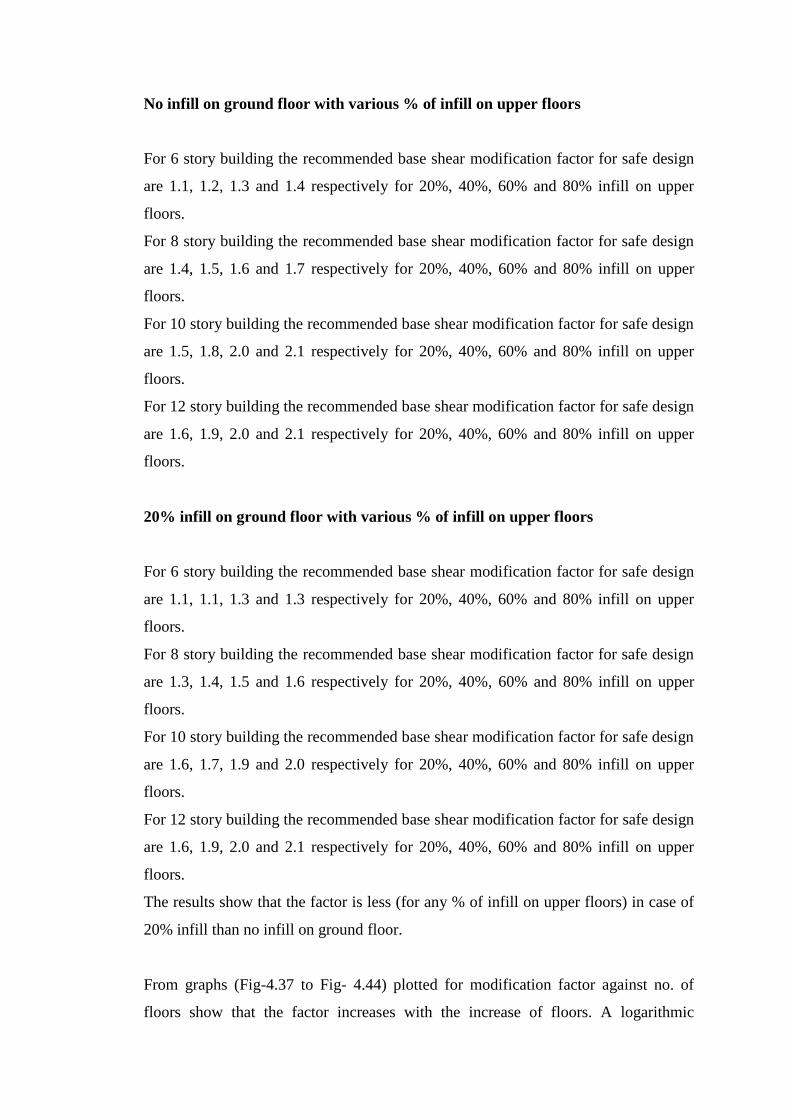
No infill on ground floor with various % of infill on upper floors
For 6 story building the recommended base shear modification factor for safe design
are 1.1, 1.2, 1.3 and 1.4 respectively for 20%, 40%, 60% and 80% infill on upper
floors.
For 8 story building the recommended base shear modification factor for safe design
are 1.4, 1.5, 1.6 and 1.7 respectively for 20%, 40%, 60% and 80% infill on upper
floors.
For 10 story building the recommended base shear modification factor for safe design
are 1.5, 1.8, 2.0 and 2.1 respectively for 20%, 40%, 60% and 80% infill on upper
floors.
For 12 story building the recommended base shear modification factor for safe design
are 1.6, 1.9, 2.0 and 2.1 respectively for 20%, 40%, 60% and 80% infill on upper
floors.
20% infill on ground floor with various % of infill on upper floors
For 6 story building the recommended base shear modification factor for safe design
are 1.1, 1.1, 1.3 and 1.3 respectively for 20%, 40%, 60% and 80% infill on upper
floors.
For 8 story building the recommended base shear modification factor for safe design
are 1.3, 1.4, 1.5 and 1.6 respectively for 20%, 40%, 60% and 80% infill on upper
floors.
For 10 story building the recommended base shear modification factor for safe design
are 1.6, 1.7, 1.9 and 2.0 respectively for 20%, 40%, 60% and 80% infill on upper
floors.
For 12 story building the recommended base shear modification factor for safe design
are 1.6, 1.9, 2.0 and 2.1 respectively for 20%, 40%, 60% and 80% infill on upper
floors.
The results show that the factor is less (for any % of infill on upper floors) in case of
20% infill than no infill on ground floor.
From graphs (Fig-4.37 to Fig- 4.44) plotted for modification factor against no. of
floors show that the factor increases with the increase of floors. A logarithmic
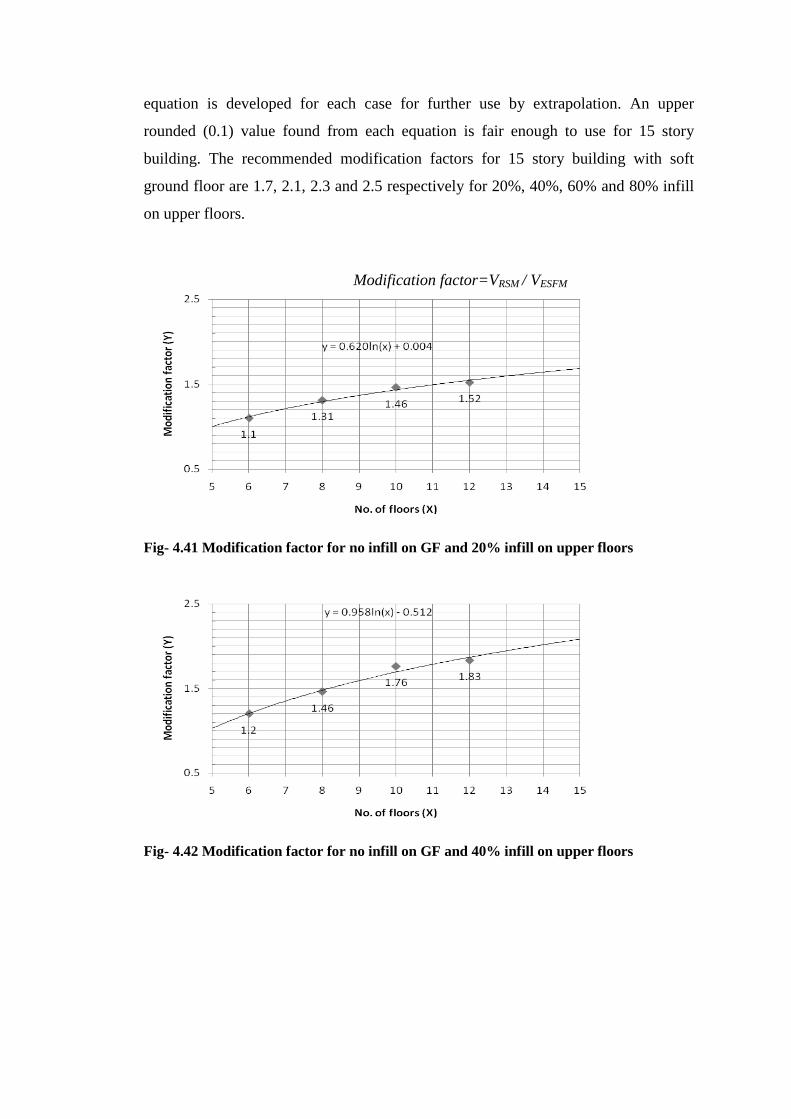
equation is developed for each case for further use by extrapolation. An upper
rounded (0.1) value found from each equation is fair enough to use for 15 story
building. The recommended modification factors for 15 story building with soft
ground floor are 1.7, 2.1, 2.3 and 2.5 respectively for 20%, 40%, 60% and 80% infill
on upper floors.
Fig- 4.41 Modification factor for no infill on GF and 20% infill on upper floors
Fig- 4.42 Modification factor for no infill on GF and 40% infill on upper floors
Modification factor=VRSM / VESFM
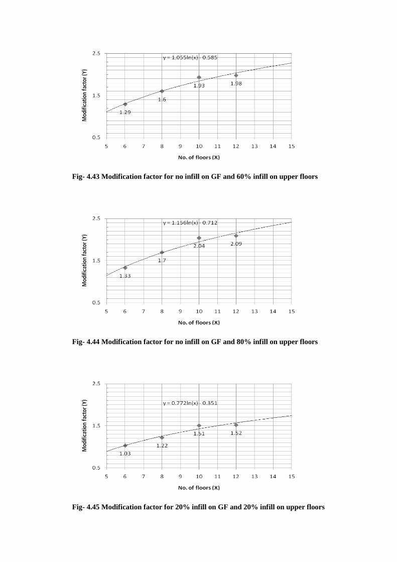
Fig- 4.43 Modification factor for no infill on GF and 60% infill on upper floors
Fig- 4.44 Modification factor for no infill on GF and 80% infill on upper floors
Fig- 4.45 Modification factor for 20% infill on GF and 20% infill on upper floors

Fig- 4.46 Modification factor for 20% infill on GF and 40% infill on upper floors
Fig- 4.47 Modification factor for 20% infill on GF and 60% infill on upper floors
Fig- 4.48 Modification factor for 20% infill on GF and 80% infill on upper floors
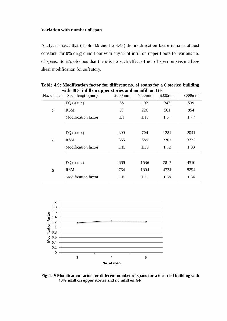
Variation with number of span
Analysis shows that (Table-4.9 and fig-4.45) the modification factor remains almost
constant for 0% on ground floor with any % of infill on upper floors for various no.
of spans. So it’s obvious that there is no such effect of no. of span on seismic base
shear modification for soft story.
Table 4.9: Modification factor for different no. of spans for a 6 storied building
with 40% infill on upper stories and no infill on GF No. of span Span length (mm) 2000mm 4000mm 6000mm 8000mm
2
EQ (static) 88 192 343 539
RSM 97 226 561 954
Modification factor 1.1 1.18 1.64 1.77
4
EQ (static) 309 704 1281 2041
RSM 355 889 2202 3732
Modification factor 1.15 1.26 1.72 1.83
6
EQ (static) 666 1536 2817 4510
RSM 764 1894 4724 8294
Modification factor 1.15 1.23 1.68 1.84
Fig-4.49 Modification factor for different number of spans for a 6 storied building with
40% infill on upper stories and no infill on GF
0
0.2
0.4
0.6
0.8
1
1.2
1.4
1.6
1.8
2
2 4 6
Mo
dif
icat
ion
Fac
tor
No. of span
CHAPTER 5
CONCLUSION AND RECOMMENDATION
5.1 GENERAL
In the present study computational investigation has been performed on reinforced
concrete frame structure having various percentage of masonry infill on upper floors
with no infill and 20% infill on ground floor. The application of infill has been done
randomly and the effect of seismic load has been investigated. The analysis was
carried for 6, 8, 10 and 12 storied buildings for 20%, 40%, 60% and 80% infill on
upper floors. For each individual case at least 10 runs have been made to study the
variation on base shear for randomly applied infill. The analysis is done both by
ESFM and RSM so that a comparison can be made on the actual MI-RC soft story
behavior with the current design practice. Based on the investigation some
modification factor has been recommended on various cases of infill application.
5.2 FINDINGS OF THE INVESTIGATION
The general output of the investigation indicates a different characteristic behavior of
infilled RC frame than from bare frames. The summary of the findings can be
tabulated as follows;
The presence of structurally active infill on upper floors causes increase in
base shear value of the building.
The random location of infill shows a range of variable base shear value for
same framing system. To use base shear modification factor for infill % less
than 50% (on upper floors), it must be considered with the average of closely
valued cases. For infill % higher than 50% (on upper floors), the variation is
not significantly large to go for several runs.
20% infill application on ground floor normally cause an insignificant
reduction on base shear value than open ground floor but for 12 story building
and 80% infill on upper floors, the base shear increases a little with 20% infill
on ground floor. It can be said that the base shear value doesn’t change much
for 20% infill on ground floor.
A safe base shear modification factor can be recommended as 1.5, 1.8, 2.0 and
2.3 for 6, 8, 10 and 12 storied building respectively. With some logical
judgment and graphical extrapolation we can recommend a factor of 2.5 for
15 storied building.
5.3 RECOMMENDATION FOR FUTURE STUDY
The current study on infill behavior with soft floor has been carried under limited
scope. The results are not sufficient to apply as so many other factors and variables
have not been studied so far. Advancement of current study can be done combining
some other variables together. The following fields related to this study can be
considered for further analysis;
The model was considered to be linearly elastic. To be more realistic with the
results a finite element analysis with non linear material properties can be
performed.
The investigation can be carried for high-rise structures with floor number
more than 20.
Rather than equivalent strut model for infill, other methods of infill modeling
can be tried to verify the results.
The asymmetric building frames can be studied under the variables considered
for symmetric frames.
Other economical ways for the remedy of infilled RC frame with soft story
mechanism should be studied as the current recommendation of considering
higher base shear value can increase the cost of construction.

REFERENCES
AFPS(1990) “Recommendations for the reaction of rules Relative to the Structures
and Installation Built in Regions Prone to Earthquakes”, French Association of
Earthquake Engineering, Paris, France.
Algerian Seismic Code (1988) “Algerian Earthquake Resistant Regulations”,
Ministry of town Planning and Construction, Algiers, Algeria.
Amanat, K. M. and Hoque, E. (2006) “A Rationale for Determining the natural
period of RC Building FramesHaving Infill” Engineering Structures, Vol.28, pp. 495-
502.
Bertero V. and Brokken S. (1983) “Infills in Seismic Resistant Building”, Journal of
the Structural Engineering, ASCE, Vol.109, No.6, June, pp.1337-1361
BNBC, (1993) Housing and Building Research Institute and Bangladesh Standards
and Testing Institution, Bangladesh National Building Code
Cost Rican Seismic Code (1986) “Seismic Code of Costa Rica”, Federal College of
Engineers and Architects of Costa Rica, San Jose, Costa Rica.
Egyptian Seismic Code (1988) “Regulations for earthquake resistant design of
buildings in Egypt”, Egyptian Society for Earthquake Engineering, Cairo, Egypt.
ESCP-1, (1983) “Code of practice for loading, Ethiopia”, Ministry of Urban
development and Housing, Addis Ababa, Ethiopia.
Holmes M. (1961) “Steel Frame with Brickwork and Concrete infilling”, Proceedings
of the Institution of Civil Engineers, Vol.-19, pp.473-478.

IS-1893 (2002) Bureau of Indian Standards, Indian Standard Criteria for Earthquake
Resistant Design of Structures-Part-1: General Provisions and Buildings (Fifth
revision), New Delhi, India
Klingner, R. E. and Bertero, V. V. (1978) “Earthquake Resistance of Infilled
Frames”, Journal of the Structural Engineering, ASCE, Vol.104, No.ST6, June,
pp.973-989
Madan A., Reinhorn A. M., Mander J. B. and Valles R. E. (1997) “Modeling of
Masonry Infill Panels for Structural Analysis”, ASCE Journal of Structural
Engineering, Vol.123, No.10, October, pp..1295-1297
Mehrabi, A. B. Shing P. B., Schuller, M. P. and Noland J. N. (1996) “Experimental
Evaluation of Masonry Infilled RC Frames”, Journal of the Structural Engineering,
ASCE, Vol.122, No.3, March, pp.228-237
Mezzi, M. (2004) “Architectural and Structural Configurations of Buildings with
Innovative seismic Systems”, 13th
World Conference on Earthquake Engineering,
August, (Paper No. 1318), Vancouver, B.C., Canada.
Mogaddam H. A., Dowling P. J. (1987) “The State of the Art in infilled Frames”,
Imperial College of Science and Technology, Civil Engineering Dept., London, UK,
ESEE Report no.87-2
Murty C. V. R.and Jain S. K. (2000) “Beneficial influence of Masonry Infills on
seismic performance of RC frame buildings”, Proceedings, 12th
World Conference on
Earthquake Engineering, New Zealand, Paper No. 1790
NBC-105, (1995) “Nepal National Building Code for For Seismic Design of
Buildings in Nepal”, Ministry of Housing and Physical Planning, Department of
Buildings, Kathmandu, Nepal.

NSR-98 (1998) “Colombian Standard for Seismic Resistant Design and
Construction”, Bogota, Columbia.
Papia M. (1998), “Analysis of Infilled Frames Using Coupled Finite Element and
Boundary Element Solution Scheme”, Int. J. Num. Meth. Eng., Vol.26, pp. 731-742
Rosenblueth, E. (1951) “A basis for Seismic Design”, Ph.D. Thesis, University of
Illinois, Urbana, Ill.
Saneinjad A. and Hobbs B. (1995) “Inelastic Design of Infilled Frames”, ASCE
Journal of Structural Engineers,Vol -121, No.4,April, pp.634-643
Smith B. S. (1962) “Lateral Stiffness of Infilled Frames”, ASCE Journal of Structural
Division,Vol-88,ST6,pp.183-199
Smith B. S. and Coull (1991) “A infilled-Frame structure, Tall building structures
analysis and design”, John Wiley & Sons, inc. 168-174
Venezuelan Seismic Code (1988) “Regulations for Earthquake Resistant Buildings”,
Commission De Normas Industriales, Covenin, Caracas, Venezuela.
Wilson, E. L. (2002) “Three dimensional static and dynamic analysis of Structures, A
physical approach with emphasis on Earthquake Engineering”, Third edition,
Computers and Structures, Inc. Berkeley, California, USA, ISBN 0-923907-00-9
Wood R. H.(1958),”The Stability of Tall Buildings.Proceedings of the Institution of
Civil Engineers”, Vol.-11, pp.69-102

APPENDIX: ANSYS SCRIPT USED IN THE ANALYSIS
FINISH
/CLEAR
!!!!!!!!DATA INPUT FOR BEAM,COLUMN AND SLAB!!!!!!
!!!!!!!! mm , N !!!!!!!
NSPAN=4 !!no of span!!
NFLOOR=6 !!no of floor!!
NBAY=NSPAN
SPANL=4000 !!span length!!
BAYW=3000
FLOORH=3000 !!floor height!!
BASE=1500 !!depth under GF to base!!
slabTh=120 !!5inch!!
unitwt=2.36e-5 !!!150pcf!!!
BDIV=4
LDIV=3
FFLOOR=1 !!!parameter for infill
generation!!!
SPMR=0 ! 1.0 FOR
FINDING SPMULT
tinfl=40 !!!total structural infill!!!
tinflf=0 !!ground floor infill %!!
*if,tinfl,LE,0,then
tinfl=0
*endif
pinflf=tinflf/2 !!!!percent infill at
ground floor!!!
nfpanl=(nspan*(nbay+1)+(nspan+1)*nbay)
ninflf=nint(nfpanl*pinflf/100)
nnflf=nfpanl*tinflf/100 !!!nnflf=no. of
infill at ground floor!!!
nnodeg=(nbay+1)*nspan*bdiv
pinfl=tinfl/2 !!!!percent infill at
other floors!!
npanel=(nspan*(nbay+1)+(nspan+1)*nbay)*(nfloor-1)
ninflx=nint(npanel*pinfl/100)
ntinfl=npanel*tinfl/100
FF=1.437e-3 !!!weight 30psf!!!
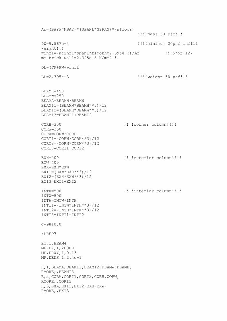
Ar=(BAYW*NBAY)*(SPANL*NSPAN)*(nfloor)
!!!!mass 30 psf!!!
PW=9.567e-4 !!!!minimum 20psf infill
weight!!!
Winfl=(ntinfl*spanl*floorh*2.395e-3)/Ar !!!5"or 127
mm brick wall=2.395e-3 N/mm2!!!
DL=(FF+PW+winfl)
LL=2.395e-3 !!!!weight 50 psf!!!
BEAMH=450
BEAMW=250
BEAMA=BEAMH*BEAMW
BEAMI1=(BEAMW*BEAMH**3)/12
BEAMI2=(BEAMH*BEAMW**3)/12
BEAMI3=BEAMI1+BEAMI2
CORH=350 !!!!corner column!!!!
CORW=350
CORA=CORW*CORH
CORI1=(CORW*CORH**3)/12
CORI2=(CORH*CORW**3)/12
CORI3=CORI1+CORI2
EXH=400 !!!!exterior column!!!!
EXW=400
EXA=EXH*EXW
EXI1=(EXW*EXH**3)/12
EXI2=(EXH*EXW**3)/12
EXI3=EXI1+EXI2
INTH=500 !!!!interior column!!!!
INTW=500
INTA=INTW*INTH
INTI1=(INTW*INTH**3)/12
INTI2=(INTH*INTW**3)/12
INTI3=INTI1+INTI2
g=9810.0
/PREP7
ET,1,BEAM4
MP,EX,1,20000
MP,PRXY,1,0.13
MP,DENS,1,2.4e-9
R,1,BEAMA,BEAMI1,BEAMI2,BEAMW,BEAMH,
RMORE,,BEAMI3
R,2,CORA,CORI1,CORI2,CORH,CORW,
RMORE,,CORI3
R,3,EXA,EXI1,EXI2,EXH,EXW,
RMORE,,EXI3
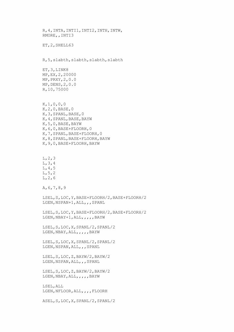
R,4,INTA,INTI1,INTI2,INTH,INTW,
RMORE,,INTI3
ET,2,SHELL63
R,5,slabth,slabth,slabth,slabth
ET,3,LINK8
MP,EX,2,20000
MP,PRXY,2,0.0
MP,DENS,2,0.0
R,10,75000
K,1,0,0,0
K,2,0,BASE,0
K,3,SPANL,BASE,0
K,4,SPANL,BASE,BAYW
K,5,0,BASE,BAYW
K,6,0,BASE+FLOORH,0
K,7,SPANL,BASE+FLOORH,0
K,8,SPANL,BASE+FLOORH,BAYW
K,9,0,BASE+FLOORH,BAYW
L,2,3
L,3,4
L,4,5
L,5,2
L,2,6
A,6,7,8,9
LSEL,S,LOC,Y,BASE+FLOORH/2,BASE+FLOORH/2
LGEN,NSPAN+1,ALL,,,SPANL
LSEL,S,LOC,Y,BASE+FLOORH/2,BASE+FLOORH/2
LGEN,NBAY+1,ALL,,,,,BAYW
LSEL,S,LOC,X,SPANL/2,SPANL/2
LGEN,NBAY,ALL,,,,,BAYW
LSEL,S,LOC,X,SPANL/2,SPANL/2
LGEN,NSPAN,ALL,,,SPANL
LSEL,S,LOC,Z,BAYW/2,BAYW/2
LGEN,NSPAN,ALL,,,SPANL
LSEL,S,LOC,Z,BAYW/2,BAYW/2
LGEN,NBAY,ALL,,,,,BAYW
LSEL,ALL
LGEN,NFLOOR,ALL,,,,FLOORH
ASEL,S,LOC,X,SPANL/2,SPANL/2
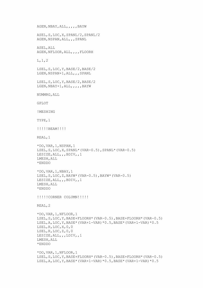
AGEN,NBAY,ALL,,,,,BAYW
ASEL,S,LOC,X,SPANL/2,SPANL/2
AGEN,NSPAN,ALL,,,SPANL
ASEL,ALL
AGEN,NFLOOR,ALL,,,,FLOORH
L,1,2
LSEL,S,LOC,Y,BASE/2,BASE/2
LGEN,NSPAN+1,ALL,,,SPANL
LSEL,S,LOC,Y,BASE/2,BASE/2
LGEN,NBAY+1,ALL,,,,,BAYW
NUMMRG,ALL
GPLOT
!MESHING
TYPE,1
!!!!!BEAM!!!!
REAL,1
*DO,VAR,1,NSPAN,1
LSEL,S,LOC,X,SPANL*(VAR-0.5),SPANL*(VAR-0.5)
LESIZE,ALL,,,BDIV,,1
LMESH,ALL
*ENDDO
*DO,VAR,1,NBAY,1
LSEL,S,LOC,Z,BAYW*(VAR-0.5),BAYW*(VAR-0.5)
LESIZE,ALL,,,BDIV,,1
LMESH,ALL
*ENDDO
!!!!!CORNER COLUMN!!!!!
REAL,2
*DO,VAR,1,NFLOOR,1
LSEL,S,LOC,Y,BASE+FLOORH*(VAR-0.5),BASE+FLOORH*(VAR-0.5)
LSEL,A,LOC,Y,BASE*(VAR+1-VAR)*0.5,BASE*(VAR+1-VAR)*0.5
LSEL,R,LOC,X,0,0
LSEL,R,LOC,Z,0,0
LESIZE,ALL,,,LDIV,,1
LMESH,ALL
*ENDDO
*DO,VAR,1,NFLOOR,1
LSEL,S,LOC,Y,BASE+FLOORH*(VAR-0.5),BASE+FLOORH*(VAR-0.5)
LSEL,A,LOC,Y,BASE*(VAR+1-VAR)*0.5,BASE*(VAR+1-VAR)*0.5
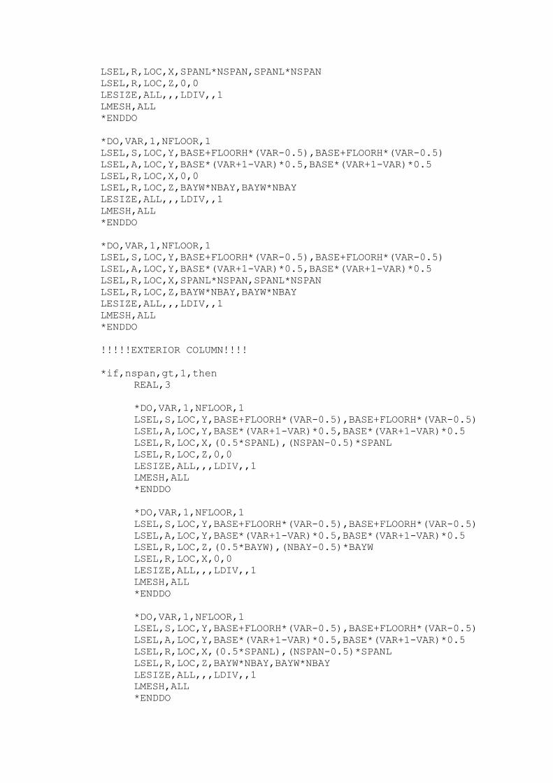
LSEL,R,LOC,X,SPANL*NSPAN,SPANL*NSPAN
LSEL,R,LOC,Z,0,0
LESIZE,ALL,,,LDIV,,1
LMESH,ALL
*ENDDO
*DO,VAR,1,NFLOOR,1
LSEL,S,LOC,Y,BASE+FLOORH*(VAR-0.5),BASE+FLOORH*(VAR-0.5)
LSEL,A,LOC,Y,BASE*(VAR+1-VAR)*0.5,BASE*(VAR+1-VAR)*0.5
LSEL,R,LOC,X,0,0
LSEL,R,LOC,Z,BAYW*NBAY,BAYW*NBAY
LESIZE,ALL,,,LDIV,,1
LMESH,ALL
*ENDDO
*DO,VAR,1,NFLOOR,1
LSEL,S,LOC,Y,BASE+FLOORH*(VAR-0.5),BASE+FLOORH*(VAR-0.5)
LSEL,A,LOC,Y,BASE*(VAR+1-VAR)*0.5,BASE*(VAR+1-VAR)*0.5
LSEL,R,LOC,X,SPANL*NSPAN,SPANL*NSPAN
LSEL,R,LOC,Z,BAYW*NBAY,BAYW*NBAY
LESIZE,ALL,,,LDIV,,1
LMESH,ALL
*ENDDO
!!!!!EXTERIOR COLUMN!!!!
*if,nspan,gt,1,then
REAL,3
*DO,VAR,1,NFLOOR,1
LSEL,S,LOC,Y,BASE+FLOORH*(VAR-0.5),BASE+FLOORH*(VAR-0.5)
LSEL,A,LOC,Y,BASE*(VAR+1-VAR)*0.5,BASE*(VAR+1-VAR)*0.5
LSEL,R,LOC,X,(0.5*SPANL),(NSPAN-0.5)*SPANL
LSEL,R,LOC,Z,0,0
LESIZE,ALL,,,LDIV,,1
LMESH,ALL
*ENDDO
*DO,VAR,1,NFLOOR,1
LSEL,S,LOC,Y,BASE+FLOORH*(VAR-0.5),BASE+FLOORH*(VAR-0.5)
LSEL,A,LOC,Y,BASE*(VAR+1-VAR)*0.5,BASE*(VAR+1-VAR)*0.5
LSEL,R,LOC,Z,(0.5*BAYW),(NBAY-0.5)*BAYW
LSEL,R,LOC,X,0,0
LESIZE,ALL,,,LDIV,,1
LMESH,ALL
*ENDDO
*DO,VAR,1,NFLOOR,1
LSEL,S,LOC,Y,BASE+FLOORH*(VAR-0.5),BASE+FLOORH*(VAR-0.5)
LSEL,A,LOC,Y,BASE*(VAR+1-VAR)*0.5,BASE*(VAR+1-VAR)*0.5
LSEL,R,LOC,X,(0.5*SPANL),(NSPAN-0.5)*SPANL
LSEL,R,LOC,Z,BAYW*NBAY,BAYW*NBAY
LESIZE,ALL,,,LDIV,,1
LMESH,ALL
*ENDDO
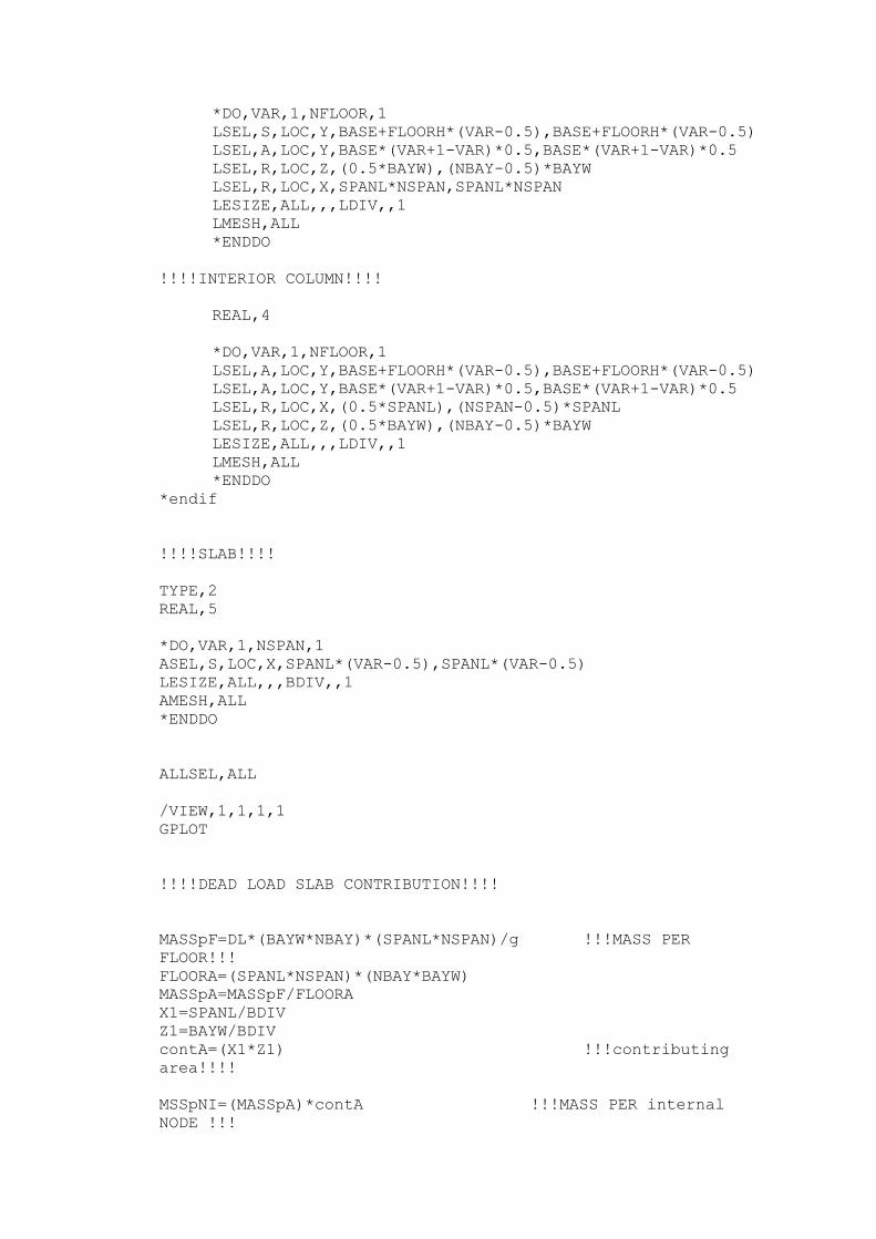
*DO,VAR,1,NFLOOR,1
LSEL,S,LOC,Y,BASE+FLOORH*(VAR-0.5),BASE+FLOORH*(VAR-0.5)
LSEL,A,LOC,Y,BASE*(VAR+1-VAR)*0.5,BASE*(VAR+1-VAR)*0.5
LSEL,R,LOC,Z,(0.5*BAYW),(NBAY-0.5)*BAYW
LSEL,R,LOC,X,SPANL*NSPAN,SPANL*NSPAN
LESIZE,ALL,,,LDIV,,1
LMESH,ALL
*ENDDO
!!!!INTERIOR COLUMN!!!!
REAL,4
*DO,VAR,1,NFLOOR,1
LSEL,A,LOC,Y,BASE+FLOORH*(VAR-0.5),BASE+FLOORH*(VAR-0.5)
LSEL,A,LOC,Y,BASE*(VAR+1-VAR)*0.5,BASE*(VAR+1-VAR)*0.5
LSEL,R,LOC,X,(0.5*SPANL),(NSPAN-0.5)*SPANL
LSEL,R,LOC,Z,(0.5*BAYW),(NBAY-0.5)*BAYW
LESIZE,ALL,,,LDIV,,1
LMESH,ALL
*ENDDO
*endif
!!!!SLAB!!!!
TYPE,2
REAL,5
*DO,VAR,1,NSPAN,1
ASEL,S,LOC,X,SPANL*(VAR-0.5),SPANL*(VAR-0.5)
LESIZE,ALL,,,BDIV,,1
AMESH,ALL
*ENDDO
ALLSEL,ALL
/VIEW,1,1,1,1
GPLOT
!!!!DEAD LOAD SLAB CONTRIBUTION!!!!
MASSpF=DL*(BAYW*NBAY)*(SPANL*NSPAN)/g !!!MASS PER
FLOOR!!!
FLOORA=(SPANL*NSPAN)*(NBAY*BAYW)
MASSpA=MASSpF/FLOORA
X1=SPANL/BDIV
Z1=BAYW/BDIV
contA=(X1*Z1) !!!contributing
area!!!!
MSSpNI=(MASSpA)*contA !!!MASS PER internal
NODE !!!
MSSpNE=0.5*(MASSpA)*contA !!!MASS PER
external NODE !!!
MSSpNC=0.25*(MASSpA)*contA !!!MASS PER corner NODE
!!!
winflf=(nnflf*floorh*bayw*127*1.88e-5) !!!ground floor
infill contribution 120pcf!!!
winflg=winflf/nnodeg
msflgf=winflg/g
massgf=msflgf/2
ALLSEL,ALL
ET,4,MASS21
MP,DENS,3,2.4e-9
R,7,MSSpNI,MSSpNI,MSSpNI !!!MASS ELEMENT
GENERATION!!!
R,8,MSSpNE,MSSpNE,MSSpNE
R,9,MSSpNC,MSSpNC,MSSpNC
R,11,-MSSpNE,-MSSpNE,-MSSpNE
R,12,massgf,massgf,massgf
ALLSEL,ALL
TYPE,4
REAL,12
YY=BASE
DELGX=SPANL/BDIV
NpSPAN=(BDIV*NSPAN+1)
*DO,G1,1,NpSPAN,1
XX=(G1-1)*DELGX
*DO,G2,1,NBAY+1,1
ZZ=(G2-1)*BAYW
E,NODE(XX,YY,ZZ)
*ENDDO
*ENDDO
ALLSEL,ALL
TYPE,4
REAL,12
YY=BASE
DELGZ=BAYW/BDIV
NpBAY=(BDIV*NBAY+1)
*DO,G3,1,NSPAN+1,1
XX=(G3-1)*SPANL
*DO,G4,1,NPBAY,1
ZZ=(G4-1)*DELGZ
E,NODE(XX,YY,ZZ)
*ENDDO
*ENDDO
ALLSEL,ALL
TYPE,4
REAL,7
*DO,ME,1,NFLOOR,1 !!!ME- MASS ELEMENT!!!
YY=BASE+ME*FLOORH
DELX=SPANL/BDIV
NpSPAN=(BDIV*NSPAN+1)
*DO,N1,2,NpSPAN-1,1
XX=(N1-1)*DELX
DELZ=BAYW/BDIV
NpBAY=(BDIV*NBAY+1)
*DO,N2,2,NpBAY-1,1
ZZ=(N2-1)*DELZ
E,NODE(XX,YY,ZZ)
*ENDDO
*ENDDO
*ENDDO
ALLSEL,ALL
TYPE,4
REAL,8
*DO,ME,1,NFLOOR,1 !!!ME- MASS ELEMENT!!!
YY=BASE+ME*FLOORH
DELX=SPANL/BDIV
NpSPAN=(BDIV*NSPAN+1)
*DO,N3,1,NpSPAN,1
XX=(N3-1)*DELX
DELZ=BAYW/BDIV
NpBAY=(BDIV*NBAY+1)
*DO,N4,1,NpBAY,NpBAY-1
ZZ=(N4-1)*DELZ
E,NODE(XX,YY,ZZ)
*ENDDO
*ENDDO
*ENDDO
ALLSEL,ALL
TYPE,4
REAL,8
*DO,ME,1,NFLOOR,1 !!!ME- MASS ELEMENT!!!
YY=BASE+ME*FLOORH
DELX=SPANL/BDIV
NpSPAN=(BDIV*NSPAN+1)
*DO,N5,1,NpSPAN,NpSPAN-1
XX=(N5-1)*DELX
DELZ=BAYW/BDIV
NpBAY=(BDIV*NBAY+1)
*DO,N6,1,NpBAY,1
ZZ=(N6-1)*DELZ
E,NODE(XX,YY,ZZ)
*ENDDO
*ENDDO
*ENDDO
ALLSEL,ALL
TYPE,4
REAL,11
*DO,ME,1,NFLOOR,1 !!!ME- MASS ELEMENT!!!
YY=BASE+ME*FLOORH
DELX=SPANL/BDIV
NpSPAN=(BDIV*NSPAN+1)
*DO,N20,1,NpSPAN,NpSPAN-1

XX=(N20-1)*DELX
DELZ=BAYW/BDIV
NpBAY=(BDIV*NBAY+1)
*DO,N21,1,NpBAY,NpBAY-1
ZZ=(N21-1)*DELZ
E,NODE(XX,YY,ZZ)
*ENDDO
*ENDDO
*ENDDO
ALLSEL,ALL
TYPE,4
REAL,9
*DO,ME,1,NFLOOR,1 !!!ME- MASS ELEMENT!!!
YY=BASE+ME*FLOORH
DELX=SPANL/BDIV
NpSPAN=(BDIV*NSPAN+1)
*DO,N7,1,NpSPAN,NpSPAN-1
XX=(N7-1)*DELX
DELZ=BAYW/BDIV
NpBAY=(BDIV*NBAY+1)
*DO,N8,1,NpBAY,NpBAY-1
ZZ=(N8-1)*DELZ
E,NODE(XX,YY,ZZ)
*ENDDO
*ENDDO
*ENDDO
ALLSEL,ALL
!!!!infill data input!!!!
*IF,SPMR,NE,1,THEN
TYPE,3
REAL,10
*if,ninflx,gt,0,then
count=0
*dim,store1,array,nspan+5,nfloor+5,nbay+5
rmainx=ninflx
*dowhile,rmainx
/gopr
Xa=nint(rand(1,nspan))
ya=nint(rand(1,nfloor-1))
za=nint(rand(1,nbay+1))
*if,store1(xa,(ya+1),za),eq,0,then
E,NODE((xa-1)*spanl,base+FLOORH+ya*FLOORH,(za-
1)*bayw),NODE(xa*spanl,(base+floorh+(ya-1)*floorh),(za-
1)*bayw)
store1(xa,(ya+1),za)=1
count=count+1
rmainx=ninflx-count
*else
count=count
rmainx=ninflx-count
*endif
*enddo
*endif
TYPE,3
REAL,10
*if,ninflx,gt,0,then
count=0
*dim,store2,array,nspan+5,nfloor+5,nbay+5
rmainx=ninflx
*dowhile,rmainx
/gopr
Xa=nint(rand(1,nspan+1))
ya=nint(rand(1,nfloor-1))
za=nint(rand(1,nbay))
*if,store2(xa,(ya+1),za),eq,0,then
E,NODE((xa-1)*spanl,base+FLOORH+ya*FLOORH,(za-
1)*bayw),NODE((xa-1)*spanl,(base+floorh+(ya-
1)*floorh),za*bayw)
store2(xa,(ya+1),za)=1
count=count+1
rmainx=ninflx-count
*else
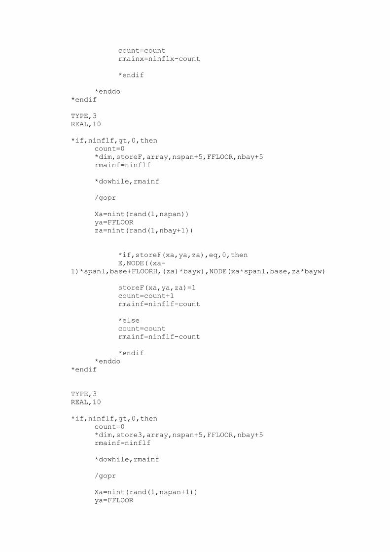
count=count
rmainx=ninflx-count
*endif
*enddo
*endif
TYPE,3
REAL,10
*if,ninflf,gt,0,then
count=0
*dim,storeF,array,nspan+5,FFLOOR,nbay+5
rmainf=ninflf
*dowhile,rmainf
/gopr
Xa=nint(rand(1,nspan))
ya=FFLOOR
za=nint(rand(1,nbay+1))
*if,storeF(xa,ya,za),eq,0,then
E,NODE((xa-
1)*spanl,base+FLOORH,(za)*bayw),NODE(xa*spanl,base,za*bayw)
storeF(xa,ya,za)=1
count=count+1
rmainf=ninflf-count
*else
count=count
rmainf=ninflf-count
*endif
*enddo
*endif
TYPE,3
REAL,10
*if,ninflf,gt,0,then
count=0
*dim,store3,array,nspan+5,FFLOOR,nbay+5
rmainf=ninflf
*dowhile,rmainf
/gopr
Xa=nint(rand(1,nspan+1))
ya=FFLOOR
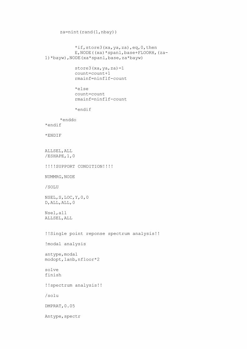
za=nint(rand(1,nbay))
*if,store3(xa,ya,za),eq,0,then
E,NODE((xa)*spanl,base+FLOORH,(za-
1)*bayw),NODE(xa*spanl,base,za*bayw)
store3(xa,ya,za)=1
count=count+1
rmainf=ninflf-count
*else
count=count
rmainf=ninflf-count
*endif
*enddo
*endif
*ENDIF
ALLSEL,ALL
/ESHAPE,1,0
!!!!SUPPORT CONDITION!!!!
NUMMRG,NODE
/SOLU
NSEL,S,LOC,Y,0,0
D,ALL,ALL,0
Nsel,all
ALLSEL,ALL
!!Single point reponse spectrum analysis!!
!modal analysis
antype,modal
modopt,lanb,nfloor*2
solve
finish
!!spectrum analysis!!
/solu
DMPRAT,0.05
Antype,spectr
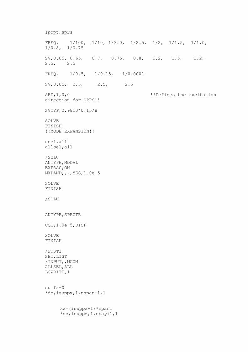
spopt,sprs
FREQ, 1/100, 1/10, 1/3.0, 1/2.5, 1/2, 1/1.5, 1/1.0,
1/0.8, 1/0.75
SV,0.05, 0.65, 0.7, 0.75, 0.8, 1.2, 1.5, 2.2,
2.5, 2.5
FREQ, 1/0.5, 1/0.15, 1/0.0001
SV,0.05, 2.5, 2.5, 2.5
SED,1,0,0 !!Defines the excitation
direction for SPRS!!
SVTYP,2,9810*0.15/8
SOLVE
FINISH
!!MODE EXPANSION!!
nsel,all
allsel,all
/SOLU
ANTYPE,MODAL
EXPASS,ON
MXPAND,,,,YES,1.0e-5
SOLVE
FINISH
/SOLU
ANTYPE,SPECTR
CQC,1.0e-5,DISP
SOLVE
FINISH
/POST1
SET,LIST
/INPUT,,MCOM
ALLSEL,ALL
LCWRITE,1
sumfx=0
*do,isuppx,1,nspan+1,1
xx=(isuppx-1)*spanl
*do,isuppz,1,nbay+1,1
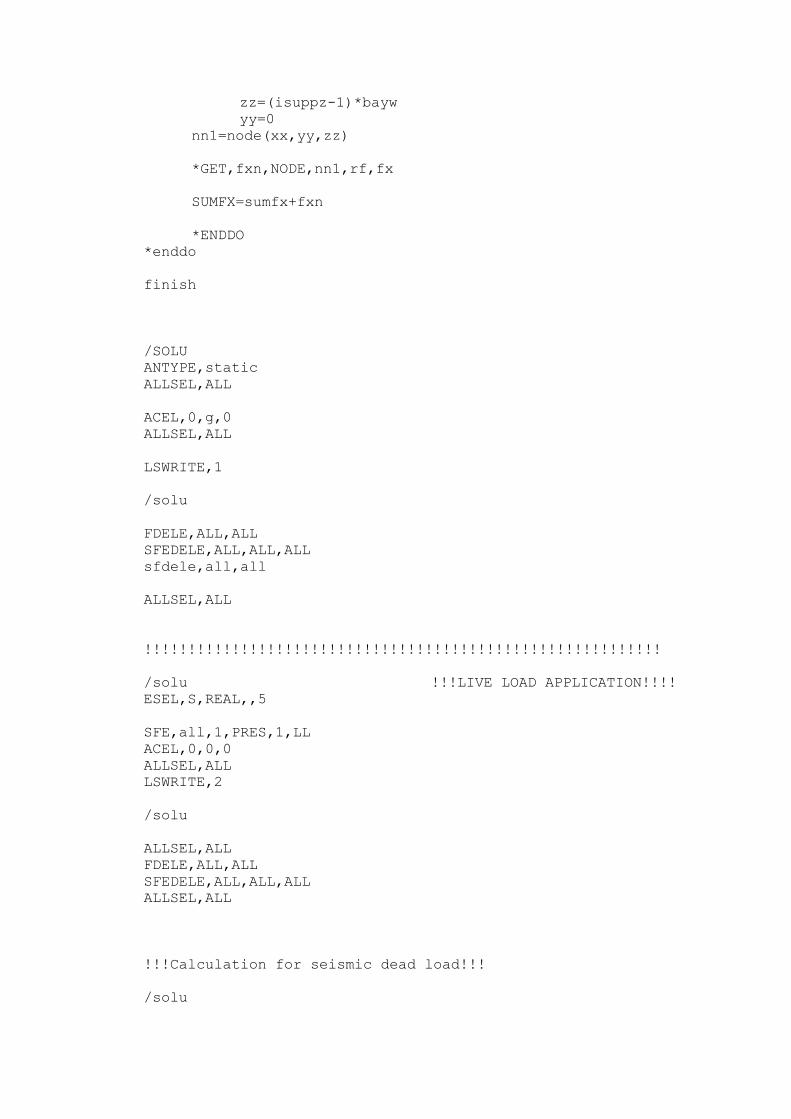
zz=(isuppz-1)*bayw
yy=0
nn1=node(xx,yy,zz)
*GET,fxn,NODE,nn1,rf,fx
SUMFX=sumfx+fxn
*ENDDO
*enddo
finish
/SOLU
ANTYPE,static
ALLSEL,ALL
ACEL,0,g,0
ALLSEL,ALL
LSWRITE,1
/solu
FDELE,ALL,ALL
SFEDELE,ALL,ALL,ALL
sfdele,all,all
ALLSEL,ALL
!!!!!!!!!!!!!!!!!!!!!!!!!!!!!!!!!!!!!!!!!!!!!!!!!!!!!!!!!!!
/solu !!!LIVE LOAD APPLICATION!!!!
ESEL,S,REAL,,5
SFE,all,1,PRES,1,LL
ACEL,0,0,0
ALLSEL,ALL
LSWRITE,2
/solu
ALLSEL,ALL
FDELE,ALL,ALL
SFEDELE,ALL,ALL,ALL
ALLSEL,ALL
!!!Calculation for seismic dead load!!!
/solu
Wb1=beamh*beamw*spanl*nspan*(nfloor)*(nbay+1)*unitwt
wgb1=beamh*beamw*spanl*nspan*(nbay+1)*unitwt
Wb2=beamh*beamw*bayw*nbay*(nfloor)*(nspan+1)*unitwt
wgb2=beamh*beamw*bayw*nbay*(nspan+1)*unitwt
Wcor=corh*corw*4*(floorh*nfloor)*unitwt
Wcoru=corh*corw*4*(base)*unitwt
Wex=exh*exw*(2*(nspan-1+nbay-1))*(floorh*nfloor)*unitwt
Wexu=exh*exw*(2*(nspan-1+nbay-1))*(base)*unitwt
wint=inth*intw*(nspan-1)*(nbay-1)*(floorh*nfloor)*unitwt
wintu=inth*intw*(nspan-1)*(nbay-1)*(base)*unitwt
Wslab=unitwt*slabTH*nspan*spanl*nbay*bayw*nfloor
Wff=FF*nspan*spanl*nbay*bayw*nfloor
Wpw=PW*nspan*spanl*nbay*bayw*nfloor
Winfll=(ntinfl*spanl*floorh*2.39e-3) !!!5"or
127 mm brick wall=2.39e-3 N/mm2!!!
wu=wgb1+wgb2+wcoru+wexu+wintu+winflf
total=(Wb1+wb2+wcor+wex+wint+wslab+wff+wpw+Winfll)
TSW=total+wu
wpf=total/nfloor
!!!seismic calculations!!!
Ct=0.073
hn=(base+nfloor*floorh)/1000
T=Ct*(hn**(3/4))
S=1.5
C=(1.25*S)/(T**(2/3))
*if,C,gt,2.75,then
C=2.75
*endif
W=TSW
Z=0.15
I=1.00
R=8
V=Z*I*C*W/R
!!!modifier to rsm!!!
spmult=-1.56466
*if,SPMR,EQ,1,then
spmult=-v/sumfx
*endif
Ft=0.0
*if,T,gt,0.7,then
Ft=0.07*T*V
*endif
*if,Ft,gt,(0.25*V),then
Ft=0.25*V
*endif
sumwhi=wu*base
*do,ifl,1,nfloor,1
sumwhi=sumwhi+wpf*(base+(floorh*ifl))
*enddo
*do,hy,base,(base+nfloor*floorh),floorh
*if,hy,eq,base,then
force=(V-Ft)*wu*hy/sumwhi
*endif
*if,hy,gt,base,then
force=(V-Ft)*wpf*hy/sumwhi
*endif
*if,hy,eq,(base+nfloor*floorh),then
force=force+Ft
*endif
*do,hz,0,nbay*bayw,bayw
f,node(0,hy,hz),fx,(force/(nbay+1))
*enddo
*enddo
ALLSEL,ALL
lswrite,3
fdele,all,all
allsel,all
LSSOLVE,1,3,1
*CFOPEN,WS,TXT
*VWRITE,W,V
(/"WEIGHT OF STRUCTURE=",F20.6,"N"//"BASE SHEAR=",F20.6,"N")
*CFCLOS
!!!POST PROCESS!!!
/post1
!!!dead load case!!!
lczero
lcdef,2,1,1
lcoper,add,2
lcwrite,2
!!!live load case!!!
lczero
lcdef,3,2,1
lcoper,add,3
lcwrite,3
!!!static EQ!!!
lczero
lcdef,4,3,1
lcoper,add,4
lcwrite,4
!!!modifying rsm method and saving as loadcase 5!!!
lczero
lcfact,1,spmult
lcoper,add,1
lcwrite,5
!!!REACTION FOR!!!
!!1. DL!!!
!!2. LL!!!
!!3. EQ STATIC!!!
!!4. EQ (response spectrum)!!!
!!!cALCULATION FOR DL!!!
LCFILE,2
LCASE,2
SUMFXD=0
SUMFYD=0
SUMFZD=0
*do,isuppx,1,nspan+1,1
xx=(isuppx-1)*spanl
*do,isuppz,1,nbay+1,1
/gopr
zz=(isuppz-1)*bayw
yy=0
nn1=node(xx,yy,zz)
*GET,fxn,NODE,nn1,rf,fx
*GET,fyn,NODE,nn1,rf,fy
*GET,fzn,NODE,nn1,rf,fz
SUMFXD=sumfxd+fxn
SUMFYD=sumfyd+fyn
SUMFZD=sumfzd+fzn
*ENDDO
*enddo
!!!calculation reaction for LL!!
LCFILE,3
LCASE,3
SUMFXL=0
SUMFYL=0
SUMFZL=0
*do,isuppx,1,nspan+1,1
xx=(isuppx-1)*spanl
*do,isuppz,1,nbay+1,1
/gopr
zz=(isuppz-1)*bayw
yy=0
nn1=node(xx,yy,zz)
*GET,fxn,NODE,nn1,rf,fx
*GET,fyn,NODE,nn1,rf,fy
*GET,fzn,NODE,nn1,rf,fz
SUMFXL=sumfxL+fxn

SUMFYL=sumfyL+fyn
SUMFZL=sumfzL+fzn
*ENDDO
*enddo
!!!calculation reaction for eq(static)!!!
LCFILE,4
LCASE,4
SUMFXS=0
SUMFYS=0
SUMFZS=0
*do,isuppx,1,nspan+1,1
xx=(isuppx-1)*spanl
*do,isuppz,1,nbay+1,1
/gopr
zz=(isuppz-1)*bayw
yy=0
nn1=node(xx,yy,zz)
*GET,fxn,NODE,nn1,rf,fx
*GET,fyn,NODE,nn1,rf,fy
*GET,fzn,NODE,nn1,rf,fz
SUMFXS=sumfxS+fxn
SUMFYS=sumfyS+fyn
SUMFZS=sumfzS+fzn
*ENDDO
*enddo
!!! calculate reaction for response spectrum method!!!
lcfile,5
lcase,5
sumfxq=0
sumfyq=0
sumfzq=0
*do,isuppx,1,nspan+1,1
xx=(isuppx-1)*spanl
*do,isuppz,1,nbay+1,1
/gopr
zz=(isuppz-1)*bayw
yy=0
nn1=node(xx,yy,zz)
*GET,fxn,NODE,nn1,rf,fx
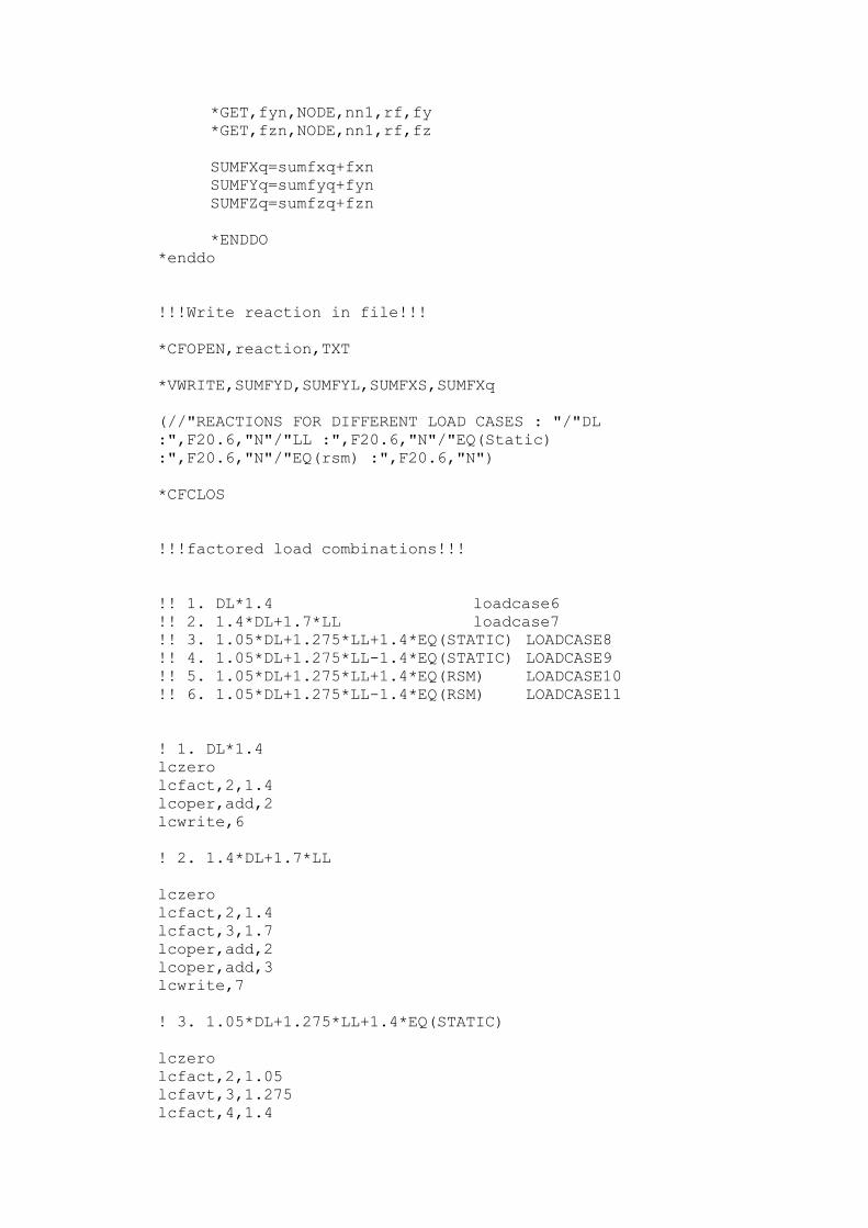
*GET,fyn,NODE,nn1,rf,fy
*GET,fzn,NODE,nn1,rf,fz
SUMFXq=sumfxq+fxn
SUMFYq=sumfyq+fyn
SUMFZq=sumfzq+fzn
*ENDDO
*enddo
!!!Write reaction in file!!!
*CFOPEN,reaction,TXT
*VWRITE,SUMFYD,SUMFYL,SUMFXS,SUMFXq
(//"REACTIONS FOR DIFFERENT LOAD CASES : "/"DL
:",F20.6,"N"/"LL :",F20.6,"N"/"EQ(Static)
:",F20.6,"N"/"EQ(rsm) :",F20.6,"N")
*CFCLOS
!!!factored load combinations!!!
!! 1. DL*1.4 loadcase6
!! 2. 1.4*DL+1.7*LL loadcase7
!! 3. 1.05*DL+1.275*LL+1.4*EQ(STATIC) LOADCASE8
!! 4. 1.05*DL+1.275*LL-1.4*EQ(STATIC) LOADCASE9
!! 5. 1.05*DL+1.275*LL+1.4*EQ(RSM) LOADCASE10
!! 6. 1.05*DL+1.275*LL-1.4*EQ(RSM) LOADCASE11
! 1. DL*1.4
lczero
lcfact,2,1.4
lcoper,add,2
lcwrite,6
! 2. 1.4*DL+1.7*LL
lczero
lcfact,2,1.4
lcfact,3,1.7
lcoper,add,2
lcoper,add,3
lcwrite,7
! 3. 1.05*DL+1.275*LL+1.4*EQ(STATIC)
lczero
lcfact,2,1.05
lcfavt,3,1.275
lcfact,4,1.4
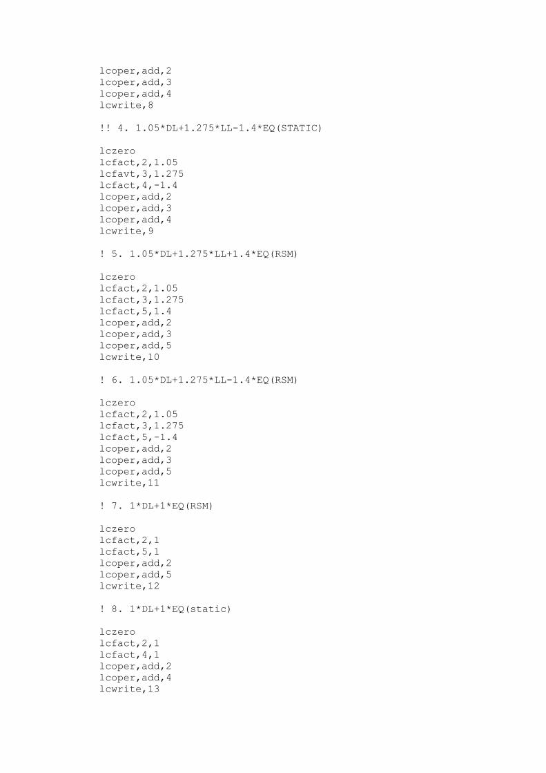
lcoper,add,2
lcoper,add,3
lcoper,add,4
lcwrite,8
!! 4. 1.05*DL+1.275*LL-1.4*EQ(STATIC)
lczero
lcfact,2,1.05
lcfavt,3,1.275
lcfact,4,-1.4
lcoper,add,2
lcoper,add,3
lcoper,add,4
lcwrite,9
! 5. 1.05*DL+1.275*LL+1.4*EQ(RSM)
lczero
lcfact,2,1.05
lcfact,3,1.275
lcfact,5,1.4
lcoper,add,2
lcoper,add,3
lcoper,add,5
lcwrite,10
! 6. 1.05*DL+1.275*LL-1.4*EQ(RSM)
lczero
lcfact,2,1.05
lcfact,3,1.275
lcfact,5,-1.4
lcoper,add,2
lcoper,add,3
lcoper,add,5
lcwrite,11
! 7. 1*DL+1*EQ(RSM)
lczero
lcfact,2,1
lcfact,5,1
lcoper,add,2
lcoper,add,5
lcwrite,12
! 8. 1*DL+1*EQ(static)
lczero
lcfact,2,1
lcfact,4,1
lcoper,add,2
lcoper,add,4
lcwrite,13

!!!deflection of different levels due to 1*DL+1*EQ(rsm)
*cfopen,drift-rsm,txt
lcfile,12
lcase,12
*do,n,1,nfloor,1
*get,sway,node,node(0,base+n*floorh,0),u,x
*vwrite,n,sway
(//"Level",F5.0,":sway=",F12.6,"mm")
*enddo
*cfclos
*cfopen,drift-static,txt
lcfile,13
lcase,13
*do,n,1,nfloor,1
*get,sway,node,node(0,base+n*floorh,0),u,x
*vwrite,n,sway
(//"Level",F5.0,":sway=",F12.6,"mm")
*enddo
*cfclos
!!topmost level deflection!!
*cfopen,deflection,txt
*do,ncase,1,11,1
lcfile,ncase
lcase,ncase
*get,sway,node,node(0,base+nfloor*floorh,0),u,x
*vwrite,ncase,sway
(//"case",F5.0,":sway=",F12.6,"mm")
*enddo
*cfclos