effect of prying action forces on design method of rigid ... · pdf fileeffect of prying...
TRANSCRIPT

1) PhD candidate
Effect of prying action forces on design method of rigid bolted connections with circular end plate
*Mohammad Reza Farajpour 1
1Department of civil engineering, Tabriz branch, Islamic Azad University, Tabriz, Iran
ABSTRACT
This paper presents an exact way for computation prying action forces in bolted rigid connections with circular end plate by studying the behavior of this type of connections. Besides, finite element models of bolted connections with circular end plate is made in various geometry. Prying action effect in these models is regarded and collapse mechanism of T connections is used to computation stiffness. Also, deformation and distribution of surface press which result from prying action phenomena is used. With using the result from parametric analyses of connections, an improved method is presented to computation prying action. Then, an improved method is proposed to design bolted rigid connections with circular end plate in regard with prying action effect. Accuracy assessment of proposed method, will display efficiency and favor accuracy in designing bolted connections with circular end plate.
Keywords: bolted rigid connections, circular end plate, finite element model, prying action forces, design method, failure models, and collapse mechanism.
1. INTRODUCTION
Well-designed connections can participate in non-linear behavior of structures and
improve its seismic behavior. Beam-column joint is the most talented point to form a plastic hinge. Suitable rotational capacity of Bolted connections allow them to prevent more lateral frame dislocation and reduce the need for ductility in beams and columns with non-elastic deformation and energy absorption, instead of merely cracking. This highlights the need for an analytical approach and detailed design of connections. Before 1994 Northridge earthquake, it was assumed that the frame with welded connections is the best system to bear gravity and lateral loads. It was expected that the failure of these frames would be limited to local submission and buckling in beams and also persistent small relative displacement between levels. Northridge earthquake caused devastation in weld joints and cracks in the heated steel section of connection parts. Since then, due to the possibility of building bolted connections factory, high safety and low cost of implementation, this type of connection is increasingly drawing the attention of the designers. (Krishnamurti 1980), heading research group of AISC Institute along with Metal Buildings Manufacturers Association MBMA, have conducted

the first studies done on the behavior and design of bolted connections. His research progressed in both theoretical and experimental areas, resulting in dozens of reports, essays and thesis. The results of this research were inserted in the (AISC Regulations 1980) as design criteria of bolted connections. With the increasing ability of computers, (Sherbourne and Bahaari 2000) designed a flat two-dimensional tension model for bolted connections using ANSYS Software and then created its 3D model. Using ABAQUS software, Willer modeled beam-to-column connections to find designing formulas (Wheeler 2000). (Daniunas and Urbonas 2006) conducted some research in the area of bolted connections at the University of Salkotekia in Lithuania. Their research was based on Europe component model and they evaluated their modeling accuracy based on experimental results of da Silva of the University of Prague (Dasilva 2001). Due to the fact that designing methods of Bolted connections are based on (Krishnamurti 1980) flat two-dimensional model, Recent advances in finite element software and accurate measurement tools have made it possible to improve analysis and designing methods providing a better understanding of the distribution of tension, strain and joint behavior.
This paper studies the behavior of endplate bolted rigid connections in two cases of skimmers and elbow (Huihuan 2016). Finite element models of the connections made by classification of Europe Regulations (EC3), have been considered full rigid (Huu Tai 2016). After checking and evaluating the accuracy of finite element models, with parametric analysis of rigid connections and T, important factors have been identified in connection behavior (Chakhari 2007). Then finite element models of T Connections with circle plate were created in different states and compared to simple T connections. One of the important parameters influencing the behavior of connections is prying action phenomenon. Designing regulations haven’t offered any exact method for calculating prying action power, and only tried to reduce its effects with increasing the reliability of design methods. In some cases this causes uneconomical design, unreal predicted behavior and a change of behavior of the structure (Smitha 2013). This paper studies the impact of prying action forces on the behavior of circular endplate rigid connections and the laws governing were developed as a mathematical model. The result of this survey is presenting an improved method for applying the effect of these forces on the behavior of this type of connections. Afterwards, methods of analysis and designing connections were studied and accuracy of each was evaluated by finite element analysis results (ANSI/AISC 2010, AISC 2005). Finally, a modified proposal for the designing bolted rigid connections was offered and the accuracy of the method was evaluated using finite element models.
2. FINITE ELEMENT MODELING
To determine the behavior of bolted connections, three groups of finite element model were developed using ABAQUS software (Abaqus element reference 2016). In order to identify factors contributing to the phenomenon of prying action, parametric analysis and calculation of the prying action forces, a group of finite element models of T connections has been created with variable endplate thickness. To compare the behavior of connections with circulated endplate, some models of T connections with circulated endplate were created and compared with simple T connections. Tables 1 and 2 show the geometry of models created. The simple connection models were used

to convergence analysis of member and evaluate the accuracy of finite element models compared with experimental results (Da silva 2001). Between finite element models, nonlinear geometric behavior, nonlinear materials and large deformations have been considered. The structure used for modeling connectivity components is solid and mechanical properties of bolt materials are of high strength A490 in three linear form with pre stressing force 150 KN and steel tip beams, columns and plates have been introduced in the software in seven linear form (Crocetti 2016). Welding in finite element models has been defined as continuous connection with TIE and reliance between connecting plate and column flange (HARD) with the separating property after unloading. In order to mesh connectivity components, the low-order tetrahedral mesh is used in three-dimensional stress state. Suitable dimensions of elements have been defined using analysis of convergence among components. Each connectivity component has been loaded and analyzed independently under different mesh and assessing the accuracy of the results of the analysis, the mesh size has been set properly. The results of bolt convergence analysis are provided in Table 3 and beam in Table 4. Fig.1 shows typical beam to beam connection models with circular endplate, Fig.2 shows circular endplate T connections and Fig.3 shows T connections with simple rectangular endplate. Fig.4 shows the finite element mesh model of samples. Tensional loading is applied in 18 stages. In model analysis stage, the non-linear geometric properties of models have been considered. To evaluate the accuracy of finite element models, Da Silva experimental data has been used (Da silva 2001).
Fig. 1 Bolted connection model with circular endplate
The comparison between experimental results and finite element of simple T connection shows accurate modeling connections. Comparing dislocation of a particular node caused by tension loading of finite element model of connection with Da Silva experimental results has shown the error of about 8%.(Da silva 2001)
2
R
2
R
cl
10.9
B cl
10.9
2
r
2
r
L L S S

Fig. 2 T connection model with circular plate
Fig. 3 Simple T Model connection
Fig. 4 Typical finite element model of sample coupling connection with circular
endplate and T connection with circular
500
500
L S t
P
L S D B X X
D Sec x-x
50
0
50
0
cl
10.9 L
t
L
2
R
2
r
S S
P

Table 1. The geometry of finite element models of simple T Connection
λ Bolt type
Bolt diameter
Hole diameter
Base plate dimension
Connection plate thickness
(t) Model
1.67 A490 20mm 22mm 500X500mm 20mm P20M20
0.3 A490 20mm 22mm 500X500mm 35.2mm P35.2M20
5 A490 20mm 22mm 500X500mm 2mm P2M20
Table2. The geometry of finite element models of circular plate
λ Bolt type
Bolt diameter
Hole diameter
Base plate dimension
Connection plate
thickness (t)
Model
1.67 A490 20mm
22mm R=250mm 20mm G20M20
0.3 A490 20mm
22mm R=250mm 35.2mm G35.2M20
5 A490 20mm
22mm R=250mm 2mm G2M20
Table 3. The results of bolted convergence
Length difference
Maximum misses stress
in bolt (pa)
Change the length of bolt
(mm)
Node number
Bolt in tension (N)
Model
- 3109.173 9101.72 Sp1-65 P=5000 Model no 1
: 0.03 seed size
- 310825.1 1210344 Sp1-65 P=1000
16% 310586.9 91099.1 Sp1-65 P=5000 Model no 2
: 0.01 seed size
16.7% 31091.1 1210413 Sp1-65 P=1000
5.6% 31047.9 9102.10 Sp1-65 P= 5000 Model no 3
(chosen model)
: 0.005 seed size
5.7% 31089.1 12104.36 Sp1-65 P=1000
3. PRYING ACTION FORCES In the design of bolted connections, regardless of lever forces causes errors in the
design. In this study, to understand the behavior of lever forces, the inter planar pressure caused by the distribution of the forces in T connections, in both simple and circular, have been checked. Factors affecting the prying action phenomenon include thickness and rigidity of the connection plate, diameter and length of the bolt, position and geometry of the hole, the mechanical properties of materials and the type of connection load. This paper studies the effect of rigidity of connection plate. λ coefficient is used to determine rigidity of connecting plate. In foundation engineering this coefficient is used to calculate foundation rigidity on elastic foundation.
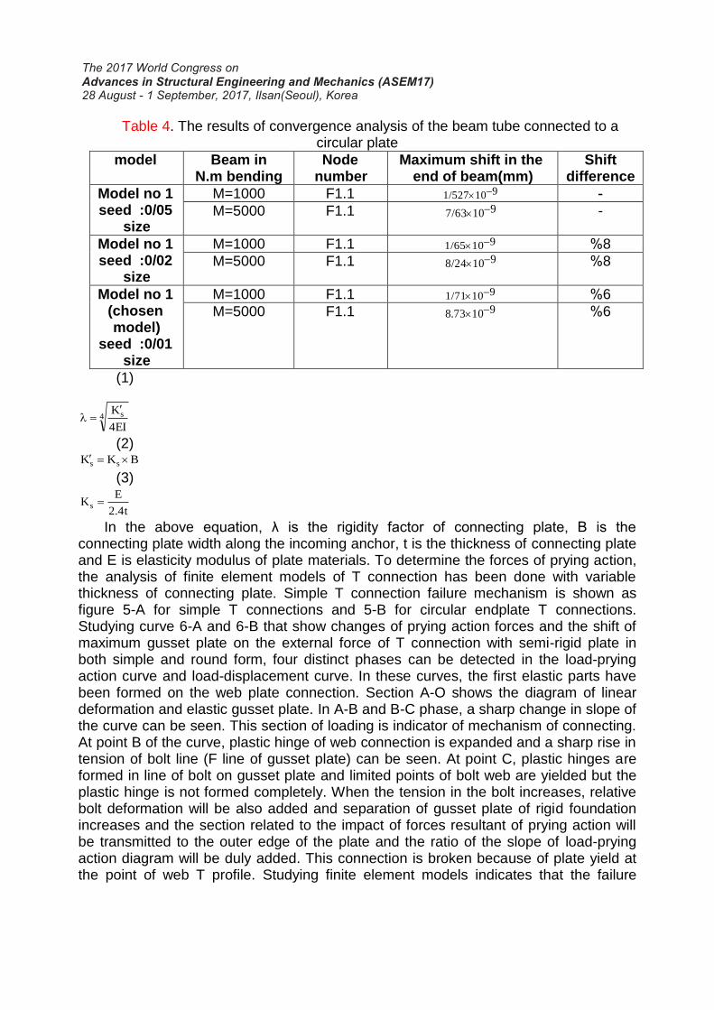
Table 4. The results of convergence analysis of the beam tube connected to a circular plate
Shift difference
Maximum shift in the end of beam(mm)
Node number
Beam in bending N.m
model
- 9101/527 F1.1 M=1000 Model no 1 :0/05 seed
size - 9107/63 F1.1 M=5000
8% 9101/65 F1.1 M=1000 Model no 1 :0/02 seed
size 8% 9108/24 F1.1 M=5000
6% 9101/71 F1.1 M=1000 Model no 1 (chosen model)
:0/01 seed size
6% 91073.8 F1.1 M=5000
(1)
4 s
EI4
K
(2) BKK ss
(3)
t4.2
EKs
In the above equation, λ is the rigidity factor of connecting plate, B is the connecting plate width along the incoming anchor, t is the thickness of connecting plate and E is elasticity modulus of plate materials. To determine the forces of prying action, the analysis of finite element models of T connection has been done with variable thickness of connecting plate. Simple T connection failure mechanism is shown as figure 5-A for simple T connections and 5-B for circular endplate T connections. Studying curve 6-A and 6-B that show changes of prying action forces and the shift of maximum gusset plate on the external force of T connection with semi-rigid plate in both simple and round form, four distinct phases can be detected in the load-prying action curve and load-displacement curve. In these curves, the first elastic parts have been formed on the web plate connection. Section A-O shows the diagram of linear deformation and elastic gusset plate. In A-B and B-C phase, a sharp change in slope of the curve can be seen. This section of loading is indicator of mechanism of connecting. At point B of the curve, plastic hinge of web connection is expanded and a sharp rise in tension of bolt line (F line of gusset plate) can be seen. At point C, plastic hinges are formed in line of bolt on gusset plate and limited points of bolt web are yielded but the plastic hinge is not formed completely. When the tension in the bolt increases, relative bolt deformation will be also added and separation of gusset plate of rigid foundation increases and the section related to the impact of forces resultant of prying action will be transmitted to the outer edge of the plate and the ratio of the slope of load-prying action diagram will be duly added. This connection is broken because of plate yield at the point of web T profile. Studying finite element models indicates that the failure

mechanism of most T connections with semi-rigid endplate (2> λ> 1.5) looks like figure 5-C. Studying 7-A and 7-B curves related to rigid plate T connections (0.5> λ> 0.3), three distinct phases are recognizable in the load-displacement and Load-prying action curves. In O-A1 phase, the curve is linear and elastic and at the point of A1 the first plastic hinges are created on gusset plate at web T. At the point of B1 the plastic hinge of the web is complete and a steep slope can be observed in order to increase the tension in the bolt axis. Also at this stage due to the formation of plastic T profile base and reduction of prying axis and the external load transmission to the web center, the slope of the load-prying action will change. At the point of C1 the gusset plate is separated from web base and limited points of the bolt axis become plastic but a complete plastic hinge is not formed there. Studying the finite element models and load-displacement and load-prying action curves of rigid plate connection of which is (0.5> λ> 0.3), this result is that figure 5 (a) is the form of failure of most of these connections and system failure is originated from web base connection.
In the connections that are high in rigidity plate (λ <0.3) the failure is originated from the bolt base and no failure happens in the gusset plate. By examining 8-A and 8-B curves which are related to the soft plate connection (4 <λ), three distinct phases in load-prying action and two phases in load-displacement diagram have been observed. In these diagrams, the O-A2 phase is linear and elastic stage while A2-B2 and B2-C2 are the connection mechanization stage. The connection failure happens at the gusset plate bolt line. Due to the softness and high ductility of the upper side of the plate, connection deformation caused by loading in the non-elastic phase, is in the form of second level curve. Examining the finite element models, figure 5-B is the form of most connection failure mechanisms with soft plates.
By examining the results of parametric T connections, it is considered that the amount of prying action forces created in the connections has direct relationship with the rigidity of gusset plate. In connection with rigid plates of (0.5> λ) the amount of prying action forces is tiny and negligible. By reducing the rigidity of gusset plates, prying action forces increase. (λ - P / Q) Curve shows that the slope of the curve of connections with super soft gusset plates (4 <λ) leans toward zero and prying action forces created in these connections are constant coefficient of external loads applied to the connection. Also (1.67 = λ) is turning point of this graph and can be considered as soft and rigid plate boundary (Fig. 8).
Table 5. Comparison between models
A B C rectangula
r
Fracture mechanism
P/2+Q P/2+Q
P
Q Q
W F G
F W
G O O
P
P/2+Q P/2+Q Q Q
W F G
F W G
P
P/2+Q Q Q
P/2+
Q
W
G
W
G O O

Connection plate yield
lines
Plastic hinges
Connection plate
moment distribution
A B C Circular
Fracture
mechanism
Connection plate yield
lines
Plastic hinges
Connection plate
moment distribution
G G cl 10.9
F F G G
cl 10.9 F F
G G cl 10.9
Q Q
P/2+Q P/2+Q
P P
Q Q
P/2+Q P/2+Q
M2
W F G
F W G
O O
B
D G G
D G F G F
B
G F G F
B
D
P/2+Q P/2+Q
P
Q Q
P/2+Q P/2+Q
Q Q
P
M2
W F G
F W G
O O
t
P
P/2+Q P/2+Q
2r
W W G G
Q Q P/2+Q P/2+Q
t
2r P
W W G G
Q Q
F F t
P/2+Q P/2+Q
2
r
P
W W G G
Q Q
F F
O O
M1
M2
M1 W F
G
F W
G
O O M1
M2
W F
G
F W
G
O O
P/2+Q P/2+Q
P
Q Q
M1
M1
M2
W F
G
F W
G
O O
M1
M2
M1
W F G
F W
G
O O
Q Q
P/2+Q P/2+Q
P
M1

MODEL P20M20 B-CURVE OF P-U
150
200
50
0.4 0.8 1.2 1.6 2 U3(mm) A-CURVE OF Q-P
100
150
200
250
50
Q(KN) 20 40 60 80
P (KN)
A B
C D
0
250
0
A B
C D P (KN)
MODEL P20M20
100
Fig. 5 Failure mechanism of T connections (at simple and circular endplate mode)
Fig. 6 The results of parametric analysis of semi-rigid T connection
Also changes in prying action forces are proportional with failure mechanism of gusset plate. In connections with rigid plate, reduction of λ value and prying action forces caused A type failure mechanism, in soft plate connections, B type failure mechanism and in connections with semi rigid plate C type failure mechanism have occurred (Fig. 5). Examining circular endplate T connections it was observed that all the results of the studying simple T connection is true for this type of the connections. The results of examining circular endplate T connection failure mechanisms are
MODEL G20M20 B-CURVE OF P-U
150
200
50
0.4 0.8 1.2 1.6 2 U3(mm) A-CURVE OF Q-P
150
200
250
50
Q(KN) 20 40 60 80
P(KN)
A B
C D
0
250
0
A B C
D P(KN)
MODEL G20M20
100

provided in Fig.5 (b). Also the failure mechanism of circular endplate beam to beam connections was quite consistent with the foregoing and one way connection to the rigid foundation or another endplate beam has no impact on the process of failure mechanism of connection point and endplate. Fig.10 shows the stress distribution in the endplate connections and also deformation of bolt and endplate in finite element models created. Sharp focus of tension in created yield line of endplates is quite evident. Fig.11 shows the distribution of tension and deformations of connections of two circular endplate beams.
Fig. 7 The results of parametric analysis of rigid T connection
B-CURVE OF P-U MODEL P35.2M20
200
300
400
500
100
P(KN)
U3(mm) A-CURVE OF Q-P
MODEL P35.2M20
Q(KN) 0.5 1 1.5 2
200
300
400
500
100
0
P(KN)
0
A1 B1
C1
0.4 0.8 1.2 2
A1
B1 C1
1.6
Q(KN)
MODEL G35.2M20 MODEL G35.2M20
200
300
400
500
100
P(KN)
0
B-CURVE OF P-U U3(mm)
A-CURVE OF Q-P 0.5 1 1.5 2
200
300
400
500
100
P(KN)
0
A1 B1
C1
0.4 0.8 1.2 2
A1
B1 C1
1.6

Fig. 8 The impact of gusset plate rigidity on the prying action forces curve
- Simple T connection ….. Circular plate T connection
Fig. 9 the results of parametric analysis of super soft T connection
CURVE OF P/Q - λ (P=2000N)
MODEL P2M20 B-CURVE OF P-U A-CURVE OF Q-P
Q(KN) 1 2 3 4 5 0.3 0.6 0.9
1
1.5
2
0.5
2.5 P(KN)
A2
B2 C2
0
P(KN)
U3(mm)
1
1.5
2
0.5
2.5
0 6
C2
MODEL P2M20
MODEL G2M20
1 2 3 4 5 B-CURVE OF P-U
0.3 0.6 A-CURVE OF Q-P
0.9
1
1.5
2
0.5
2.5 P(KN)
A2
B2 C2
0 Q(KN)
P(KN)
U3(mm)
1
1.5
2
0.5
2.5
0 6
C2
MODEL G2M20
4
6
8
0.
4
1
0
2
0.8 1.
2 1.
6 2 2.
4 2.
8 3.2 3.
6 4 4.4
P/Q
λ 0
λ=1.67

A B
C Fig.10 A: Circular endplate T connections finite element model failure B: Endplate
deformation under loading C: Deformation and failure mechanism of the bolt under loading
Fig. 11 Finite element model failure of circular endplate couple T connections
4. THE CALCULATION OF THE PRYING ACTION FORCE ON SIMPLE T CONNECTIONS
(Faella, 1999) conducted extensive studies in the field of calculation of the prying action forces resulted in providing approximation methods in a certain type of T connections (Cavdar 2009). Smith et al., provided and approximation formula to calculate prying action force (Smith 1991). In this formula that is presented to calculate prying action forces in T connections under tensile loading, the connection plates are assumed quite rigid. The applied bolts are type A490 and the connection loading is pure tensile and in the web of the profile T. Eq. 4 presents the Smith approximation formula.
(4)
]t.L.21D.a.62
t.L.14D.b.100[FQ
2f
2
2f
2

In the above equation D is the nominal diameter of the bolt, F is the external tension of a bolt, tf is the connection plate thickness, b is the distance of the bolt axis to the center of the profile T web, a is the distance between the bolt axis to the edge of the plate and L is the length of the connection plate height that includes a bolt (L= h/n). By evaluating the accuracy of this formula on finite element models of connection T an error about 80-160% is resulted in the calculation of the prying action force. Due to the high error of this formula, the use of this method to calculate the prying action forces in T connections. In the Code AISC-LRFD an approximation methods is presented for the calculation of prying action forces (AISI 2010). In this method the prying action forces in T connections are calculated by the Eq.5.
(5)
2).(...ct
tQ
In this equation, Q is the prying action forces of a bolt, β is the design tension of the bolt, ρ is the bolt axis distance from the web edge to bolt axis distance from the plate edge ratio, δ is the plate width coefficient or the plate net width to its nominal width ratio in the rows of bolt holes, α is the connection plate moment in bolt row (M1) to plate
moment in bolt row (M2) ratio in the unit width, t is the plate thickness and ct is the thickness needed to withstand the anchor of the external loading (Fig.12). This computational method is provided for certain scenarios of the T-shaped connections and its error in the connections with semi-rigid plate (λ= 1.67) is about 40% and by reducing the thickness and rigidity of the connection plate and increasing the prying action forces, its error is increased. This error has increased to 80 percent in the quite soft connections.
Fig. 12 The geometry of AISC computational method
a b a b
2
T
Q T+Q T+Q Q
M1
M2

Fig. 13 The inter planar pressure caused by prying action forces
5. THE CALCULATION OF PRYING ACTION FORCE IN T CONNECTIONS WITH CIRCULAR ENDPLATE
For the accurate calculation of prying action force in T connections with circular endplate, the geometric factors that affect the empirical relation 4 should be modified. Prying action forces are calculated by inter planar compressive stress caused by these forces based on Figure 13.Based on the difference in the stress distribution in circular plates with triangular plates due to the border cleaning of the bolts on the four sides of the connection plate and by its fitting the numerical information of the models with rent geometric conditions, the geometric factors of the plates in which the bolt hole is at the center of the distance between the edge of the beam connected to the endplate and the free end of the plate is defined as follows (Farajpour 2013).
(6)
ba 886.0
In this equation b is the distance between the bolt edge and the tensile flange wing
and a is the distance between the bolt edge and the inter planar pressure area. a is the maximum possible length to extend the contact pressure by the prying action phenomenon in the tensile bolts of the connections with the circular endplate. Fig.13 shows the stress distribution in these connections. By calculating the geometric factor the following process is recommended for calculating the prying action forces at each bolt.
(6)
nh
Mrut
1
(8)
a
b
(9)
1p
d
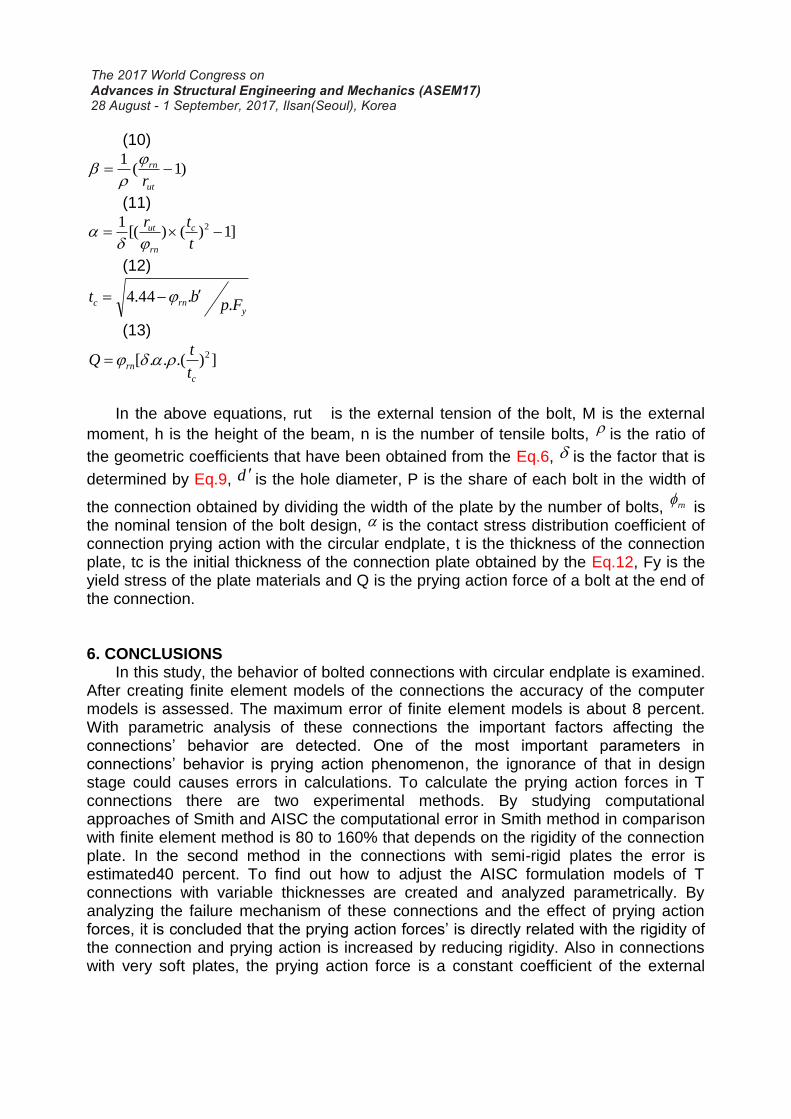
(10)
)1(1
ut
rn
r
(11)
]1)()[(1 2
t
tr c
rn
ut
(12)
yrnc Fp
bt.
.44.4
(13)
]).(..[ 2
c
rnt
tQ
In the above equations, rut is the external tension of the bolt, M is the external
moment, h is the height of the beam, n is the number of tensile bolts, is the ratio of
the geometric coefficients that have been obtained from the Eq.6, is the factor that is
determined by Eq.9, d is the hole diameter, P is the share of each bolt in the width of
the connection obtained by dividing the width of the plate by the number of bolts, rn is
the nominal tension of the bolt design, is the contact stress distribution coefficient of connection prying action with the circular endplate, t is the thickness of the connection plate, tc is the initial thickness of the connection plate obtained by the Eq.12, Fy is the yield stress of the plate materials and Q is the prying action force of a bolt at the end of the connection.
6. CONCLUSIONS In this study, the behavior of bolted connections with circular endplate is examined.
After creating finite element models of the connections the accuracy of the computer models is assessed. The maximum error of finite element models is about 8 percent. With parametric analysis of these connections the important factors affecting the connections’ behavior are detected. One of the most important parameters in connections’ behavior is prying action phenomenon, the ignorance of that in design stage could causes errors in calculations. To calculate the prying action forces in T connections there are two experimental methods. By studying computational approaches of Smith and AISC the computational error in Smith method in comparison with finite element method is 80 to 160% that depends on the rigidity of the connection plate. In the second method in the connections with semi-rigid plates the error is estimated40 percent. To find out how to adjust the AISC formulation models of T connections with variable thicknesses are created and analyzed parametrically. By analyzing the failure mechanism of these connections and the effect of prying action forces, it is concluded that the prying action forces’ is directly related with the rigidity of the connection and prying action is increased by reducing rigidity. Also in connections with very soft plates, the prying action force is a constant coefficient of the external

forces applied to the connection. In rigid connections, it is possible to ignore prying action forces under certain conditions. By comparing the distribution of contact stress obtained by prying action phenomenon in connections with simple and circular endplate and the fitting of the numerical data obtained from finite element models, the geometric factor of 0.886 is proposed for the connections with circular endplate if the bolt hole is in the middle of the beam edge and the free edge of the plate. In calculating the prying action forces with the improved method, the maximum error is estimated to be 5% in the anticipation of these forces at connections. Also using the improved method it is possible to anticipate the need to calculate prying action force in semi-rigid connections. By calculating the prying action forces and their inclusion in the process of designing, it is possible to reduce this computational and design error significantly.
REFERENCES Krishnamurthy, N. (1980) "Modeling and prediction of steel bolted connection behavior."
Journal of Computers & Structures, 11(2), pp. 75-82. Bahaari, M. R. Sherburne, Archibald, N. (2000) "Behavior of eight-bolt large capacity end-
plate connections." Journal of Computers & Structures, 77, pp. 315-325. Wheeler, A. T., Clarke, M. J. and Hancock, G. J. (2000) "FE Modeling of four-bolt, tubular
moment end-plate connections." Journal of Structural Engineering, ASCE, 126(7), pp. 816-822.
Urbonas, K., Daniunas, A. (2006). "Behavior of semi-rigid steel beam-to-beam joints under bending and axial forces." Journal of construction steel research, 62, pp. 1244-1249.
Simoes-da-Silva, L., lima, L., Vellasco, P. and De Andrade, S. (2001). "Experimental behavior of end-plate beam to column joints under bending and axial force." Eccs technical committee 10, twg10.2, Department of civil engineering, University of Coimbra.
Huihuan Ma, Shan Ren and Feng Fan, A. (2016). " Experimental and numerical research on a new semi-rigid joint for single-layer reticulated structures." Journal of Engineering Structures, 126, pp. 725-738.
Huu-Tai Thai and Brian Uy. (2016). " Rotational stiffness and moment resistance of bolted endplate joints with hollow or CFST columns." Journal of Constructional Steel Research, 126, pp. 139-152.
Chakhari and Zghal, A. (2007). “Numerical model for bolted T-stubs with two bolt rows.” Journal of Structural Engineering and Mechanics, 26(3).
Smitha, M. S. and Satish Kumar S. R. (2013). " Steel–concrete composite flange plate connections, finite element modeling and parametric studies." Journal of Constructional Steel Research, 82, pp. 164-176.
American institute of steel construction, ANSI/AISC. (2010). "Specification for structural steel building."
American Institute of Steel Construction. (2005) "Manual of steel construction, Load and resistance factor design." connections, Chicago.
Abaqus Element Reference. (2016). "Abaqus documentation." Online help. Crocetti, R. Gustafsson P. J. Girhammar, U. A., Costa, L. and Asimakidis, A. (2016).
"Nailed Steel Plate Connections: Strength and Ductile Failure Modes." Journal of Structures, 8(1), pp. 44-52.

Cavdar, O., Bayraktar, A. Cavdar, A. and Kartal, M. E. (2009) "Stochastic finite element analysis of structural systems with partially restrained connections subjected to seismic loads." Steel and Composite Structures, 9(2), pp. 123-135.
Smith, J.C. (1991). "Structural steel design lrfd approach." North Carolina State University, Wiley Inc.
Farajpour, M. R. (2013). "Effect of beam to column connections on static and seismic response of steel frames" M.Sc. thesis, Azad university, Maraghe branch, Iran.
Farajpour, M. R., Hosseinzadeh, Y. and Lotfollahiyaghin, M. A.(2013). "Effect of prying action forces on rigid end plate connections" journal of Sharif, 4, pp. 3-13.