effect of geomagnetically induced currents on … of geomagnetically induced currents on protection...
TRANSCRIPT

Effect of Geomagnetically Induced Currents on Protection Systems
Sture Lindahl2004-01-23
Industrial Electrical Engineering and [email protected]

Sture Lindahl, LTH/IEA 2
Effect of GIC on Protective RelaysActivity of the Sun
Propagation of the Solar Wind
Magnetospheric Processes
Ionospheric Processes
Earth Surface Potential
Geomagnetically Induced Currents
Saturation of Power Transformers
Performance of Protective Relays

Sture Lindahl, LTH/IEA 3
Solar Flare Effects

Sture Lindahl, LTH/IEA 4
Geomagnetically Induced Currents
GICGIC
Earth Surface Potential Gradient-+
GIC
Electrojet
GIC

Sture Lindahl, LTH/IEA 5
Conclusions
• The risk is that protective relays operate unwantedly during a geomagnetic storm and causes a severe power system disturbance or even a nationwide blackout
• A less obvious risk is that the current transformers operates so far into saturation that the secondary current is too low for proper operation of the protection equipment at internal faults during geomagnetic storms.

Sture Lindahl, LTH/IEA 6
Protective Relays at Risk
• The most important class of relays is the non-directional low set residual overcurrent relays commonly applied on– shunt capacitors,– power transformers,– shunt reactors, and– transmission lines

Sture Lindahl, LTH/IEA 7
Shunt Capacitors
• International operational experience shows very clearly that low-set residual overcurrent relays for shunt capacitors with directly earthed neutral point are very vulnerable.
• So far, protective relays for shunt capacitors is Sweden have not maloperated during geomagnetic storms.
• It is recommended that the setting and the harmonic restraint of the (1) residual overcurrent and(2) neutral-point overcurrent relay are reviewed and tested.

Sture Lindahl, LTH/IEA 8
Power Transformers
• Security of transformer protection• There are some protective relays for power
transformers that should be reviewed and tested. The candidates are:– (1) the low-set residual overcurrent relay,– (2) the low-set neutral-point overcurrent relay, and– (3) the restricted earth-fault relay.
• The same holds true for similar protective relays applied on directly earthed shunt reactors.

Sture Lindahl, LTH/IEA 9
Power Transformers
• Dependability of transformer protection• Are the power transformers sufficiently
protected in case of GIC?• Power transformers and shunt reactors
are in general equipped with mechanical and thermal fault detectors.
• These fault detectors operate independently of the instrument transformers and may keep up the dependability

Sture Lindahl, LTH/IEA 10
Transformer Damage
Sture Lindahl, LTH/IEA 11
400- 220- and 130-kV Power Lines
• Operational experience shows that the low-set residual overcurrent relays are vulnerable to GICs.
• In 1986, all such relays on the 400- and 220-kV network were replaced by modern dependent time overcurrent relays with logarithmic characteristic and second harmonic restraint.
• There are, however, a number of residual over-current relays applied on power lines that have inadequate performance.

Sture Lindahl, LTH/IEA 12
Residual Overcurrent Relays
• Future low-set residual overcurrent relays should preferably just measure the fundamental frequency component of the current.
• How to justify that the dependent time residual overcurrent relay must operate at 150 Hz? (SNDR-requirement)
• It should also be possible to restrain the relay not only from the second harmonic but also from other harmonics.

Sture Lindahl, LTH/IEA 13
GIC Disturbance 2003-11-20
• 400-kV Hemsjö-Karlshamnsverket with the HVDC converter for SwePo Link
• 400 MW import from Poland interrupted• The residual overcurrent dependent
time relay operated unexpectedly.

Sture Lindahl, LTH/IEA 14
GIC Disturbance 2003-11-20
Recordings Hemsjö 2003-11-20
0
50
100
150
200
0 500 1000 1500 2000 2500 3000
Time [ms]
Cu
rren
t [A
]
RMS(Ires) RMS(3I0)

Sture Lindahl, LTH/IEA 15
GIC Disturbance 2003-11-20
Recordings Hemsjö 2003-11-20, Harm(3I0)
0.006 0.004
0.144
0.0050.004
0.120
0.0050.002
0.004
1E-4
1E-3
1E-2
1E-1
1E+0
1E+1
Fund 2nd 3rd 4th 5th 6th 7th 8th 9th
Rel
ativ
e M
agn
itu
de

Sture Lindahl, LTH/IEA 16
GIC Disturbance 2003-11-20
Recordings Hemsjö 2003-11-20, Harm(Ires)
0.013
0.002
0.140
0.003 0.003
0.134
0.003 0.0030.004
1E-4
1E-3
1E-2
1E-1
1E+0
1E+1
Fund 2nd 3rd 4th 5th 6th 7th 8th 9th
Rel
ativ
e M
agn
itu
de

Sture Lindahl, LTH/IEA 17
GIC Disturbance 2003-11-20
Recordings Hemsjö 2003-11-20 (3i0)
-1000
-500
0
500
1000
260 280 300 320 340 360
Time [ms]
Cu
rren
t [A
]
Sture Lindahl, LTH/IEA 18
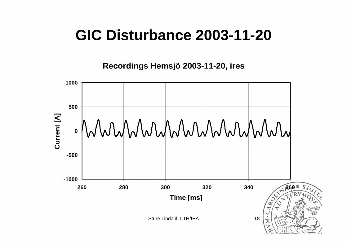
GIC Disturbance 2003-11-20
Recordings Hemsjö 2003-11-20, ires
-1000
-500
0
500
1000
260 280 300 320 340 360
Time [ms]
Cu
rren
t [A
]

Sture Lindahl, LTH/IEA 19
GIC Disturbance 2003-11-20
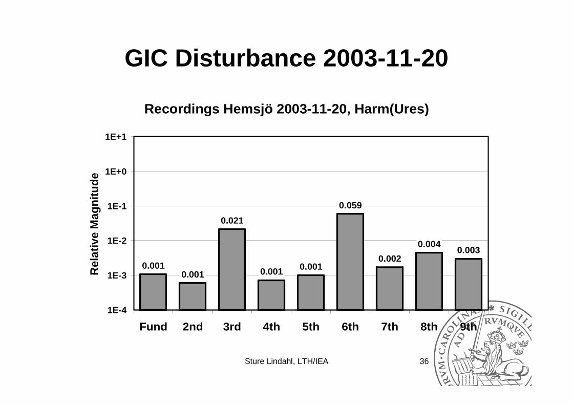
Recordings Hemsjö 2003-11-20, Harm(Ures)
0.0010.001
0.021
0.001 0.001
0.059
0.002
0.0040.003
1E-4
1E-3
1E-2
1E-1
1E+0
1E+1
Fund 2nd 3rd 4th 5th 6th 7th 8th 9th
Rel
ativ
e M
agn
itu
de

Sture Lindahl, LTH/IEA 20
GIC Disturbance 2003-11-20
Recordings Hemsjö 2003-11-20, ures
-400
-200
0
200
400
260 280 300 320 340 360
Time [ms]
Vo
ltag
e [k
V]

Sture Lindahl, LTH/IEA 21
GIC Disturbance 2003-11-20
• The relay operation is caused by the 3rd
and 6th harmonic current and not by the fundamental frequency current
• The stabilising 2nd harmonic in the residual current is very low
• SNDR has requested that the residual current dependent time relay must operate for the 3rd harmonic

Sture Lindahl, LTH/IEA 22
Three-Phase System Model (Ch 5)
AC Source
DC Source
Transformer Load ShuntCapacitor

Sture Lindahl, LTH/IEA 23
Magnetising Inductance
Relative Incremental Magnetising Inductance
-0.5
0.0
0.5
1.0
1.5
-20 -10 0 10 20
(Magnetising Current)/Is
Mag
net
isin
g In
du
ctan
ce
Saturated Region Saturated Region
Non-Saturated Region

Sture Lindahl, LTH/IEA 24
Magnetising Inductance
Incremental Magnetising Reactance
0
25
50
75
100
125
-10 -5 0 5 10
Relative Magnetising Current
Mag
net
isin
g R
eact
ance
ms= 6 ms= 10 ms= 14

Sture Lindahl, LTH/IEA 25
Analytical or Dynamic Simulation
RMS-Value of Magnetising Current
0
100
200
300
400
500
0 50 100 150 200 250
(DC Current)/Is
(RM
S-V
alu
e)/Is

Sture Lindahl, LTH/IEA 26
Analytical or Dynamic Simulation
Peak-Value of Magnetising Current
0
100
200
300
400
500
0 50 100 150 200 250
(DC Current)/Is
(Pea
k-V
alu
e)/Is
Sture Lindahl, LTH/IEA 27
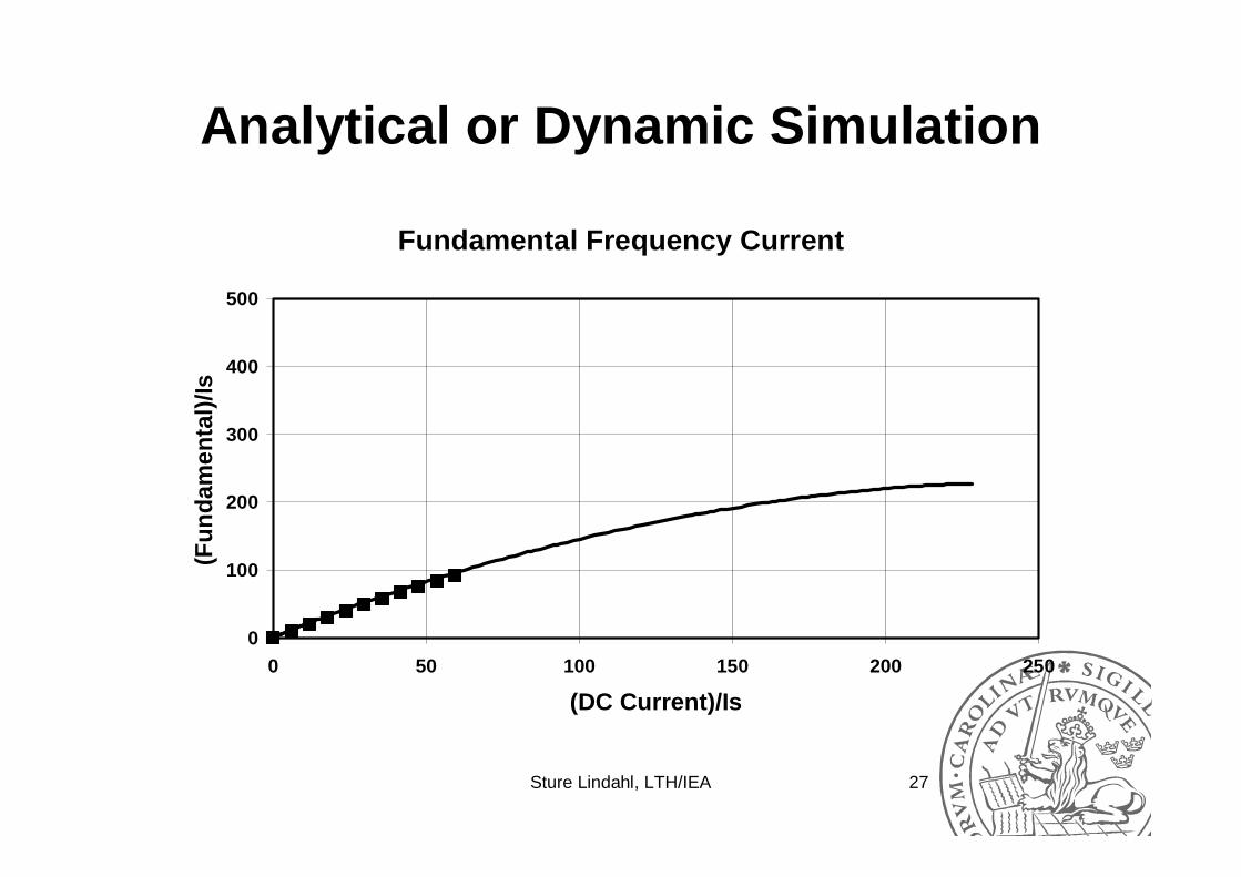
Analytical or Dynamic Simulation
Fundamental Frequency Current
0
100
200
300
400
500
0 50 100 150 200 250
(DC Current)/Is
(Fu
nd
amen
tal)
/Is

Sture Lindahl, LTH/IEA 28
Analytical or Dynamic Simulation
Second Harmonic Current
-40
-20
0
20
40
60
0 50 100 150 200 250
(DC Current)/Is
(Sec
on
d H
arm
on
ic)/
Is

Sture Lindahl, LTH/IEA 29
Analytical or Dynamic Simulation
Third Harmonic Current
-40
-20
0
20
40
60
0 50 100 150 200 250
(DC Current)/Is
(Th
ird
Har
mo
nic
)/Is

Sture Lindahl, LTH/IEA 30
Analytical or Dynamic Simulation
• Both methods give similar results• Saturating power transformers cause a
reduction of the busbar voltage• Saturating power transformers cause
both even and odd harmonics (k=1 to 9)• Higher order harmonics not accurate• The analytical method gives upper limit

Sture Lindahl, LTH/IEA 31
Busbar Voltages (Ch 7)
Busbar Voltage
400
405
410
415
420
0 10 20 30 40 50 60
(Direct Current per Phase)/Is
Vo
ltag
e [k
V]

Sture Lindahl, LTH/IEA 32
Busbar Voltages
Total Harmonic Distortion
0
1
2
3
4
5
0 10 20 30 40 50 60
(Direct Current per Phase)/Is
TH
D [
%]

Sture Lindahl, LTH/IEA 33
Busbar Voltages
Magnitude and Phase Angle of Second Harmonic
0.00
0.01
0.02
0.03
0.04
0.0 6.0 11.9 17.8 23.8 29.7 35.6 41.6 47.5 53.5 59.4
(Direct Current per Phase)/Is
Mag
nit
ud
e V
2/V
1
-180
-90
0
90
180
An
gle
[d
egre
es]
Magnitude Phase Angle
Sture Lindahl, LTH/IEA 34
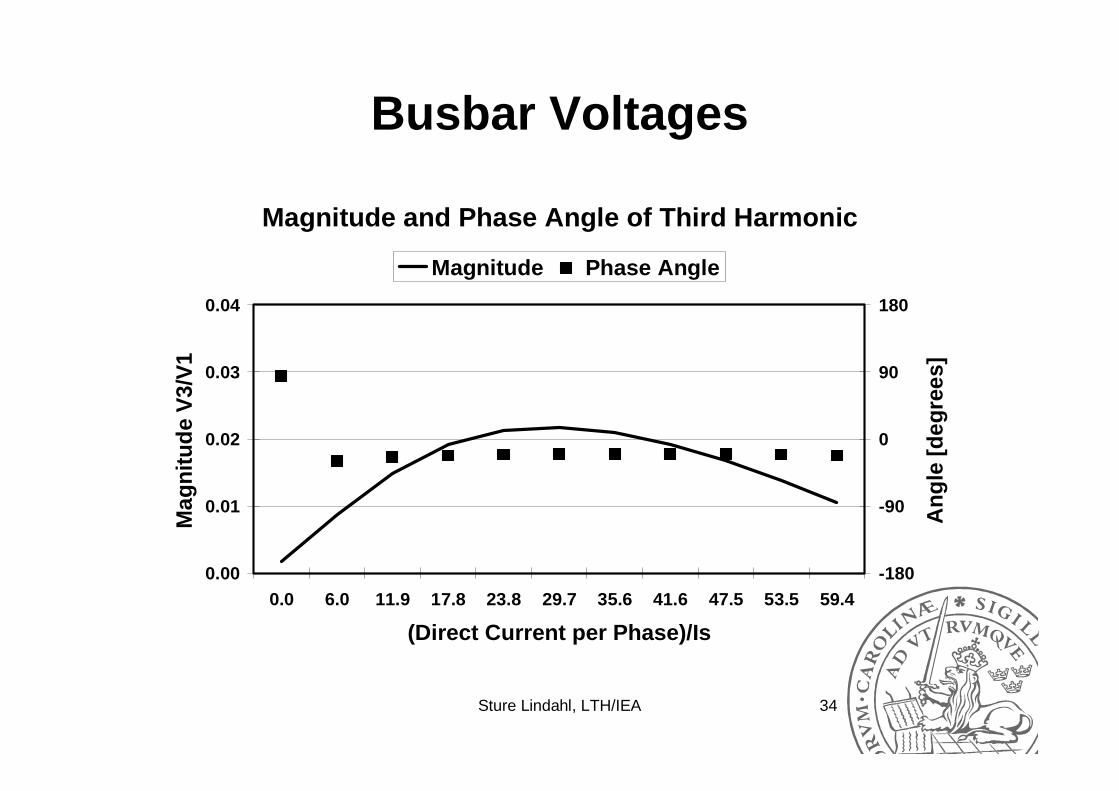
Busbar Voltages
Magnitude and Phase Angle of Third Harmonic
0.00
0.01
0.02
0.03
0.04
0.0 6.0 11.9 17.8 23.8 29.7 35.6 41.6 47.5 53.5 59.4
(Direct Current per Phase)/Is
Mag
nit
ud
e V
3/V
1
-180
-90
0
90
180
An
gle
[d
egre
es]
Magnitude Phase Angle
Sture Lindahl, LTH/IEA 35
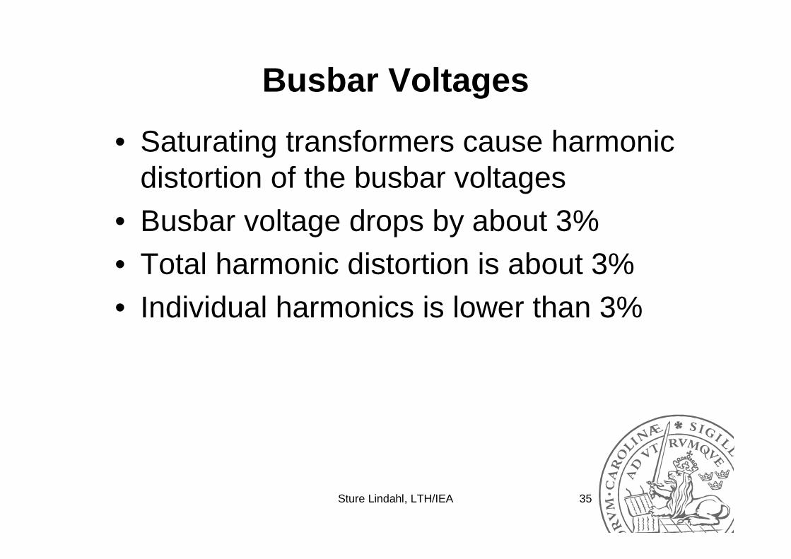
Busbar Voltages
• Saturating transformers cause harmonic distortion of the busbar voltages
• Busbar voltage drops by about 3%• Total harmonic distortion is about 3%• Individual harmonics is lower than 3%
Sture Lindahl, LTH/IEA 36
GIC Disturbance 2003-11-20
Recordings Hemsjö 2003-11-20, Harm(Ures)
0.0010.001
0.021
0.001 0.001
0.059
0.002
0.0040.003
1E-4
1E-3
1E-2
1E-1
1E+0
1E+1
Fund 2nd 3rd 4th 5th 6th 7th 8th 9th
Rel
ativ
e M
agn
itu
de

Sture Lindahl, LTH/IEA 37
Earthed Shunt Capacitors (Ch 9)
Phase Currents at 200 Mvar (Idc/Is=5.94)
-600
-400
-200
0
200
400
600
0 20 40 60 80 100
Time [ms]
Cu
rren
t [A
]
Phase a Phase b Phase c

Sture Lindahl, LTH/IEA 38
Earthed Shunt Capacitors
Total Harmonic Distortion of the Phase Currents
0
5
10
15
20
0 10 20 30 40 50 60
(Direct Current per Phase)/Is
TH
D [
%]

Sture Lindahl, LTH/IEA 39
Earthed Shunt Capacitors
Magnitude and Phase Angle of Third Harmonic
0.00
0.05
0.10
0.15
0.20
0.0 6.0 11.9 17.8 23.8 29.7 35.6 41.6 47.5 53.5 59.4
(Direct Current per Phase)/Is
Mag
nit
ud
e I3
/I1
-180
-90
0
90
180
An
gle
[d
egre
es]
Magnitude Phase Angle

Sture Lindahl, LTH/IEA 40
Earthed Shunt Capacitors
Magnitude and Phase Angle of 6th Harmonic
0.00
0.05
0.10
0.15
0.20
0.0 6.0 11.9 17.8 23.8 29.7 35.6 41.6 47.5 53.5 59.4
(Direct Current per Phase)/Is
Mag
nit
ud
e I6
/I1
-180
-90
0
90
180
An
gle
[d
egre
es]
Magnitude Phase Angle

Sture Lindahl, LTH/IEA 41
Earthed Shunt Capacitors
RMS-value of Residual Current
0.0
0.1
0.2
0.3
0.4
0.5
0 10 20 30 40 50 60
(Direct Current per Phase)/Is
(Res
idu
al C
urr
ent)
/In

Sture Lindahl, LTH/IEA 42
Earthed Shunt Capacitors
Magnitude and Phase Angle of Second Harmonic
0.00
0.01
0.02
0.03
0.04
0.0 5.9 11.9 17.8 23.7 29.7 35.6 41.5 47.5 53.4 59.3
(Direct Current per Phase)/Is
I2/In
-180
-90
0
90
180
An
gle
[d
egre
es]
Magnitude Phase Angle

Sture Lindahl, LTH/IEA 43
Earthed Shunt Capacitors
Magnitude and Phase Angle of Third Harmonic
0.0
0.1
0.2
0.3
0.4
0.0 5.9 11.9 17.8 23.7 29.7 35.6 41.5 47.5 53.4 59.3
(Direct Current per Phase)/Is
I3/In
-180
-90
0
90
180
An
gle
[d
egre
es]
Magnitude Phase Angle

Sture Lindahl, LTH/IEA 44
Earthed Shunt Capacitors
Magnitude and Phase Angle of 6th Harmonic
0.0
0.1
0.2
0.3
0.4
0.0 5.9 11.9 17.8 23.7 29.7 35.6 41.5 47.5 53.4 59.3
(Direct Current per Phase)/Is
I6/In
-180
-90
0
90
180
An
gle
[d
egre
es]
Magnitude Phase Angle

Sture Lindahl, LTH/IEA 45
Earthed Shunt Capacitors
• The fundamental frequency phase current decreases because of the busbar voltage
• The total harmonic distortion in the phase current is higher than 10%
• The 3rd harmonic of the phase current is higher than 6% of the phase current while the 6th harmonic is higher than 10%
• The RMS value of the residual current is about 40% while the 6th harmonic is higher than 20%.

Sture Lindahl, LTH/IEA 46
Current Transformers (Ch 12)
pi′pi
:pn snI I :1
si
sΨ
Lλ wR bL
bRse

Sture Lindahl, LTH/IEA 47
Instrument Transformers (Ch 10)
• How to determine the B-H characteristic from the V-I characteristic?

Sture Lindahl, LTH/IEA 48
Experimental Data
Magnetising Curve
10
100
1000
10000
0.1 1.0 10.0 100.0 1000.0
I [mA]
U [
V]
U [V]
Sture Lindahl, LTH/IEA 49
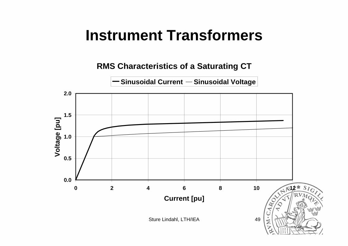
Instrument Transformers
RMS Characteristics of a Saturating CT
0.0
0.5
1.0
1.5
2.0
0 2 4 6 8 10 12
Current [pu]
Vo
ltag
e [p
u]
Sinusoidal Current Sinusoidal Voltage

Sture Lindahl, LTH/IEA 50
Instrument Transformers
• It seems reasonable to use the RMS value of the magnetising current at the knee point and use that value to determine when the magnetising inductance drops from the non-saturated value to the saturated value

Sture Lindahl, LTH/IEA 51
Current Transformers
Harmonic Content of Secondary Current
0
500
1000
1500
2000
2500
100 200 500 1000 1500 2500
Magnitude of Direct Current, IDC [A]
Am
plit
ud
e [A
]
Fundamental 2nd 3rd 4th 5th 6th

Sture Lindahl, LTH/IEA 52
Future Work
• Requirements on the dependent time residual overcurrent relay for power lines and power transformers
• Protection for earthed shunt capacitors• How to protect power transformers
against GIC?