eexpansion jointxpansion joint metal expansion joints.pdfmatchless expansion joints unafl ex®...
TRANSCRIPT

2
EXPANSION JOINTEXPANSION JOINTA Leader in
Manufacturing
No other manufacturer in the United States has the capabilities of Unafl ex®. We are a full service expansion joint manufacturer offering a full range of fl exible components and customer support. We offer a full range of products in the highest grades of stainless steel, as well as more exotic alloys including Monel®, Inconel® and Hastelloy®.
Unafl ex® Quality control is rigorous and complies with requirements of MIL-I-45208 and MIL-Q-9858. Our Expansion Joints also comply with U.S. Coast Guard requirements. Certifi cation is available.
Our expertise and manufacturing capabilities include Bellows-Type Metal Expansion Joints and Connectors, Rubber Expansion Joints, Tefl on® Expansion Joints, Fabric Expansion Joints, Metal Hose and Pump Connectors. Unafl ex® is one of the few companies in the world that can offer a complete expansion joint and hose product line. This catalog outlines the selection and installation of our Metal Bellows Type Expansion Joints and Pump Connectors for use in piping/ducting systems along with process equipment to absorb thermal movement. Our products incorporate the latest recommendations of the Expansion Joint Manufacturers Association (EJMA).

3
Overview Engineering Capabilities Industry Codes Materials Used Manufacturing Capabilities
Standard Expansion Joints Matchless Expansion Joints Tied Universal Joints Externally Pressurized Joints Series 5000 Pump Connectors Tube Flex Engine Exhaust Joints
Matchless Expansion Joints Dual Expansion Joints Elbow Pressure Balanced Expansion Joints
Technical Information Installation Instructions Metal Expansion Joint Types Accessories Key Concepts
Warranty
General Ordering Information
Table of Contents

4
Engineering Capabilities
Unafl ex® utilizes various engineering software programs to provide expansion joints in accordance with customer requirements for the utmost reliability. Some of these programs are industry-leading programs such as Finite Element Analysis (FEA) CAD/CAM and Expansion Joint Manufacturers Association (EJMA). Our products are fully engineered to industry accepted standards.
Overview
Stress distribution on a double ring with gussets hardware
Temperature distribution on a fl oating hardware assembly
Temperature distribution on afl oating ring assembly
Stress Distribution on a ring to pipe attachment

5
Industry Codes
Unafl ex® expansion joints are manufactured in accordance with EJMA’s latest edition. Other Industry Standards that Unafl ex® manufacturing can conform to but are not limited to, include: • ASME B31.3 • ASME B31.1 • MIL-I-45208 • MIL-Q-9858 • U.S. Coast Guard Requirements
• A/SA240 304ss • A/SA240 304Lss • A/SA240 316ss • A/SA240 316Lss • A/SA240 310S • B/SB443 Alloy 625 (Inconel® 625) • B/SB168 Alloy 600 (Inconel® 600) • B/SB575 Alloy C276 (Hastelloy®C276)
• B/SB575 Alloy C22 (Hastelloy®C22) • B/SB127 ALLOY 400 (Monel® 400) • B/SB409 ALLOY 800 • Duplex ALLOY 2205• Hastelloy® X• Nickel 200• Alloy 20• AL6XN
Bellows Material Specifi cation
Unafl ex® standard bellows material is A/SA240 321ss. Other materials available to Unafl ex® to manufacture bellows are:
Manufacturing Capabilities
Unafl ex® maintains an in-house machine shop complete with computer-controlled fl ame cutting capabilities, a high-speed laser machine and a water jet machine which enable us to provide a full range of metal working capabilities.
We are able to manufacture bellows from 2” ND to 144” ND as our standard with the capability to manufacture to 222” (18’-6”). We have both die forming and roll forming capabilities. We can perform in house dye-penetrant test, hydro and pneumatic pressure test, helium leak test and PMI (Positive Material Identifi cation) by fully qualifi ed Quality Control Personnel.
Unafl ex® welders are qualifi ed in accordance with ASME Section IX latest edition (procedures available for review upon request). We stock various types of bellows materials, fl anges, plates, pipe and threaded rods for fast response and delivery times.

6
Matchless Expansion JointsUnafl ex® “MATCHLESS” bellows are manufactured from solution annealed A/SA240 321SS sheet rolled into a tube and seam welded. Multi-ply bellows can be designed and manufactured based on the application and design requirements. Unafl ex® has a wide variety of materials available to design and manufacture bellows.
Unafl ex® has the most commonly used bellows materials and thicknesses in stock to serve our customers faster. Unafl ex® “MATCHLESS” bellows conform to the latest EJMA standards.
Overall lengths of standard assemblies are based on 150# drilling for both plate fl ange and raised face slip on thicknesses. Overall length may change if other types of fl anges are requested. Overall lengths of the SHP and LHD series are based on 300# are raised face slip on fl anges.
Fixed Plate Flanges–Type 44Unafl ex® Type 44 expansion joints are with 150# drill carbon steel fl anges (AWWA Class D C207) fi xed on each end of the expansion joint. Bellows necks are welded directly to the fl anges.
Floating Plate Flanges–Type 66Unafl ex® Type 66 expansion joints are provided with 150# drill carbon steel fl anges (AWWA class D C207) fl oating on each end of the expansion joint. Bellows necks are fl ared (Vanstone) to retain the fl anges.
Floating fl ange arrangement allows use of carbon steel fl anges when all wetted materials are required to be either Stainless Steel or an alloy material. Floating fl anges also permit bolt hole alignment in the fi eld.
Weld Ends–Type 22Unafl ex® Type 22 expansion joints are provided with carbon steel weld ends on each end. Weld ends are beveled per ANSI standards. Schedule 40 (sch std.) pipe is used through 12” ND and 1/4” wall thickness for sizes over 12” unless otherwise specifi ed.
Raised Face Slip On Flanges Type–55Unafl ex® Type 55 expansion joints are provided with 150# drill and 300# drill carbon steel raised face fl anges.

7
Short Style Specifi cation Chart Style 55
Size(in.) Series Pressure
(PSIG) O.A.L. Weight(lbs.)
Spring Rates (lbs./in.)
Axial Lateral
2SLPSMPSHP
50150300
666
111115
0.64 0.16 0.1681681681
945945945
2.5SLPSMPSHP
50150300
66
6.5
151521
0.64 0.16 0.1664664
1,253
1,3041,3042,469
3SLPSMPSHP
50150300
667
171727
0.64 0.16 0.1703703
1,343
1,9621,9623,760
3.5SLPSMPSHP
50150300
667
232335
0.64 0.16 0.1728728
1,342
2,1322,1323,938
4SLPSMPSHP
50150300
77
7.5
272745
0.64 0.16 0.1756756
1,410
2,7402,7405,118
5SLPSMPSHP
50150300
888
313158
1.04 0.26 0.1564581
2,150
3,0882,328
10,931
6SLPSMPSHP
50150300
889
404081
1.04 0.260.20.10.1
337744
2,846
1,9733,975
14,368
8SLPSMPSHP
50150300
99.511
6364
1231.28 0.32
0.20.10.1
250901
2,833
1,3074,720
14,893
10SLPSMPSHP
50150300
9.59.511
8991
1691.28 0.32 0.1
3971,3464,119
3,27311,12034,129
12SLPSMPSHP
50150300
101012
132134242
1.28 0.32 0.1309
1,5347,148
3,07514,34262,597
14SLPSMPSHP
50150300
10.510.512.5
184189348
1.28 0.32 0.1356
1,8993,797
4,18120,72141,651
16SLPSMPSHP
50150300
111113
202206400
1.28 0.32 0.1651
2,4524,887
9,44935,62659,981
18SLPSMPSHP
50150300
121214
267272524
1.44 0.36 0.1559
2,3804,721
10,22943,36572,641
20SLPSMPSHP
50150300
121214
342347665
1.44 0.36 0.1753
2,9605,818
17,18167,035
132,337
22SLPSMPSHP
50150300
1212.514.5
379389779
1.44 0.36 0.1599
3,2486,380
16,03583,910
139,960
24SLPSMPSHP
50150300
131315
455461992
1.44 0.36 0.1898
3,5446,958
28,938108,343180,225
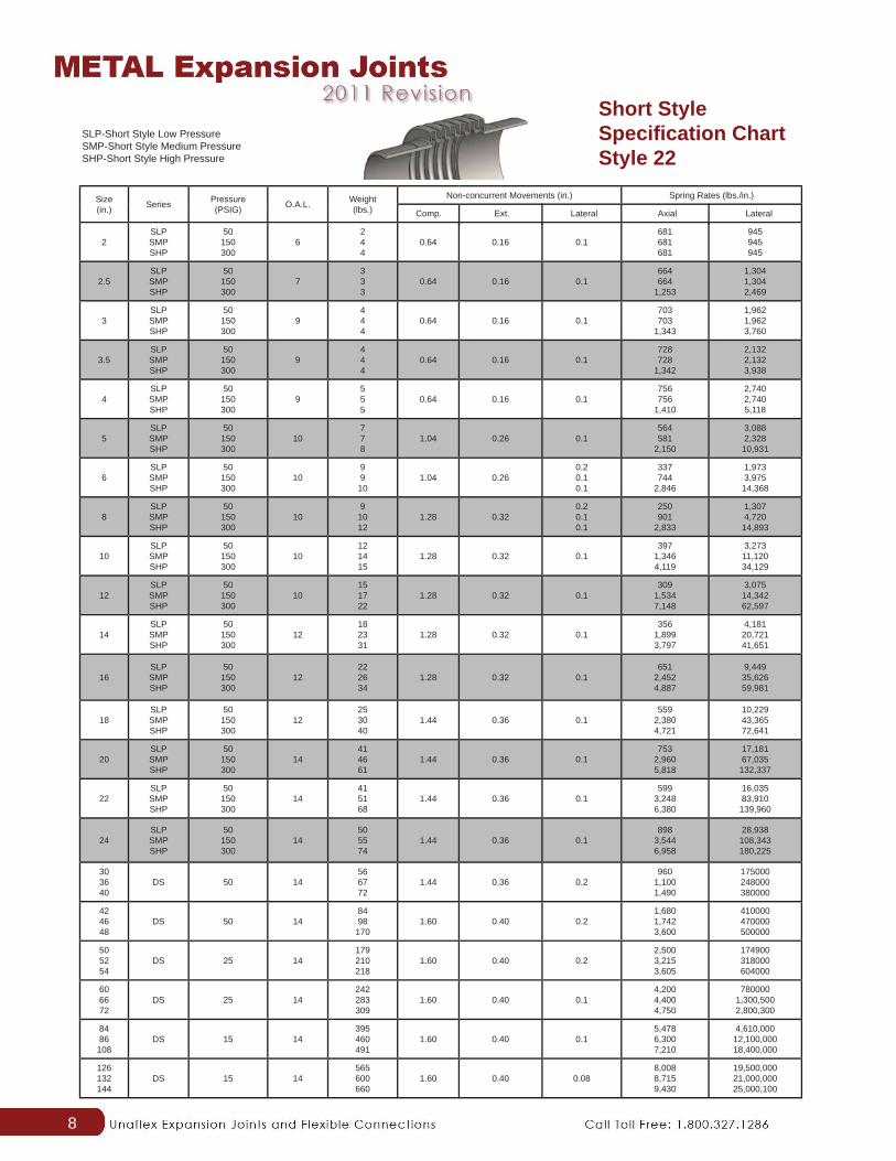
Comp. Ext. Lateral
Non-current Movements (in.)
SLP-Short Style Low PressureSMP-Short Style Medium PressureSHP-Short Style High Pressure
8
Size(in.) Series Pressure
(PSIG) O.A.L. Weight(lbs.)
Non-concurrent Movements (in.) Spring Rates (lbs./in.)
2SLPSMPSHP
50150300
6244
0.64 0.16 0.1681681681
945945945
2.5SLPSMPSHP
50150300
7333
0.64 0.16 0.1664664
1,253
1,3041,3042,469
3SLPSMPSHP
50150300
9444
0.64 0.16 0.1703703
1,343
1,9621,9623,760
3.5SLPSMPSHP
50150300
9444
0.64 0.16 0.1728728
1,342
2,1322,1323,938
4SLPSMPSHP
50150300
9555
0.64 0.16 0.1756756
1,410
2,7402,7405,118
5SLPSMPSHP
50150300
10778
1.04 0.26 0.1564581
2,150
3,0882,328
10,931
6SLPSMPSHP
50150300
109910
1.04 0.260.20.10.1
337744
2,846
1,9733,975
14,368
8SLPSMPSHP
50150300
1091012
1.28 0.320.20.10.1
250901
2,833
1,3074,720
14,893
10SLPSMPSHP
50150300
10121415
1.28 0.32 0.1397
1,3464,119
3,27311,12034,129
12SLPSMPSHP
50150300
10151722
1.28 0.32 0.1309
1,5347,148
3,07514,34262,597
14SLPSMPSHP
50150300
12182331
1.28 0.32 0.1356
1,8993,797
4,18120,72141,651
16SLPSMPSHP
50150300
12222634
1.28 0.32 0.1651
2,4524,887
9,44935,62659,981
18SLPSMPSHP
50150300
12253040
1.44 0.36 0.1559
2,3804,721
10,22943,36572,641
20SLPSMPSHP
50150300
14414661
1.44 0.36 0.1753
2,9605,818
17,18167,035132,337
22SLPSMPSHP
50150300
14415168
1.44 0.36 0.1599
3,2486,380
16,03583,910139,960
24SLPSMPSHP
50150300
14505574
1.44 0.36 0.1898
3,5446,958
28,938108,343180,225
303640
DS 50 14566772
1.44 0.36 0.2960
1,1001,490
175000248000380000
424648
DS 50 148498
1701.60 0.40 0.2
1,6801,7423,600
410000470000500000
505254
DS 25 14179210218
1.60 0.40 0.22,5003,2153,605
174900318000604000
606672
DS 25 14242283309
1.60 0.40 0.14,2004,4004,750
7800001,300,5002,800,300
8486
108DS 15 14
395460491
1.60 0.40 0.15,4786,3007,210
4,610,00012,100,00018,400,000
126132144
DS 15 14565600660
1.60 0.40 0.088,0088,7159,430
19,500,00021,000,00025,000,100
Comp. Ext. Lateral Axial Lateral
SLP-Short Style Low PressureSMP-Short Style Medium PressureSHP-Short Style High Pressure
Short Style Specifi cation Chart Style 22

9
SLP-Short Style Low PressureSMP-Short Style Medium PressureSHP-Short Style High Pressure
Size(in.) Series Pressure
(PSIG) O.A.L. Weight(lbs.)
Non-concurrent Movements (in.) Spring Rates (lbs./in.)
2SLPSMPSHP
50150300
6101010
0.64 0.16 0.1681681681
945945945
2.5SLPSMPSHP
50150300
6131313
0.64 0.16 0.1664664
1,253
1,3041,3042,469
3SLPSMPSHP
50150300
6131313
0.64 0.16 0.1703703
1,343
1,9621,9623,760
3.5SLPSMPSHP
50150300
6202020
0.64 0.16 0.1728728
1,342
2,1322,1323,938
4SLPSMPSHP
50150300
7181818
0.64 0.16 0.1756756
1,410
2,7402,7405,118
5SLPSMPSHP
50150300
8212122
1.04 0.26 0.1564581
2,150
3,0882,328
10,931
6SLPSMPSHP
50150300
8262627
1.04 0.260.20.10.1
337744
2,846
1,9733,975
14,368
8SLPSMPSHP
50150300
8463740
1.28 0.320.20.10.1
250901
2,833
1,3074,720
14,893
10SLPSMPSHP
50150300
8464850
1.28 0.32 0.1397
1,3464,119
3,27311,12034,129
12SLPSMPSHP
50150300
9767884
1.28 0.32 0.1309
1,5347,148
3,07514,34262,597
14SLPSMPSHP
50150300
9107112121
1.28 0.32 0.1356
1,8993,797
4,18120,72141,651
16SLPSMPSHP
50150300
9138142152
1.28 0.32 0.1651
2,4524,887
9,44935,62659,981
18SLPSMPSHP
50150300
10149154166
1.44 0.36 0.1559
2,3804,721
10,22943,36572,641
20SLPSMPSHP
50150300
10191196214
1.44 0.36 0.1753
2,9605,818
17,18167,035
132,337
22SLPSMPSHP
50150300
10219229249
1.44 0.36 0.1599
3,2486,380
16,03583,910
139,960
24SLPSMPSHP
50150300
11265271292
1.44 0.36 0.1898
3,5446,958
28,938108,343180,225
303640
DS 50 11377497602
1.44 0.36 0.2960
1,1001,490
175,000248,000380,000
424648
DS 50 11641750810
1.60 0.40 0.21,6801,7423,600
410,000470,000500,000
505254
DS 25 11900
1,0081,061
1.60 0.40 0.22,5003,2153,605
174,900318,000604,000
606672
DS 25 111,3471,5911,799
1.60 0.40 0.14,2004,4004,750
780,0001,300,5002,800,300
8486
108DS 15 11
2,1373,9163,200
1.60 0.40 0.15,4786,3007,210
4,610,00012,100,00018,400,000
126132144
DS 15 114,4004,7005,200
1.60 0.40 0.088,0088,7159,430
19,500,00021,000,00025,000,100
Comp. Ext. Lateral Axial Lateral
Short Style Specifi cation Chart Style 44 and 66Style 44 Style 66
10
Size(in.) Series Pressure
(PSIG) O.A.L. Weight(lbs.)
Non-concurrent Movements (in.) Spring Rates (lbs./in.)
2LLPLMPLHP
50150300
888
111115
1.60
0.96
0.40
0.24
0.50.30.3
389483
1,052
180219471
2.5LLPLMPLHP
50150300
1010
10.5
151522
1.60
1.20
0.40
0.30
0.50.30.2
279688
1,403
105253896
3LLPLMPLHP
50150300
9.59.511
171828
1.60
1.20
0.40
0.30
0.60.40.3
312721
1,474
166379778
3.5LLPLMPLHP
50150300
108.59.5
232436
1.60
1.28
0.40
0.32
0.60.40.3
336589
1,209
228686
1,284
4LLPLMPLHP
50150300
101011
282847
1.60
1.28
0.40
0.32
0.60.40.3
378743
1,564
342671
1,412
5LLPLMPLHP
50150300
1111.513
333461
2.40
1.60
0.60
0.40
0.50.50.4
242922
1,760
249862
1,601
6LLPLMPLHP
50150300
121213
414387
2.40
1.76
0.60
0.44
0.750.6
0.45
260762
1,924
3691,0032,292
8LLPLMPLHP
50150300
131315
6769126
3.20
2.08
0.80
0.52
0.750.550.4
5411,0141,846
9511,7883,240
10LLPLMPLHP
50150300
12.512.514
9197173
3.20
2.08
0.80
0.52
0.60.450.3
263984
2,318
8563,3446,826
12LLPLMPLHP
50150300
14.515
16.5
136141251
3.20
2.08
0.80
0.52
0.80.50.3
3351,14411,532
1,0153,3113,971
14LLPLMPLHP
50150300
151516
189195358
2.88 0.720.70.50.4
3591,0552,373
1,2913,8508,924
16LLPLMPLHP
50150300
15.515.516.5
206213411
2.88 0.720.70.40.4
3621,3623,054
1,6766,318
14,233
18LLPLMPLHP
50150300
15.51617
272279537
2.88 0.720.5
0.350.3
4191,5883,257
2,4159,163
19,258
20LLPLMPLHP
50150300
151517
342349673
2.88 0.720.40.30.3
4281,7213,134
3,76114,29026,708
22LLPLMPLHP
50150300
16.517
18.5
387399793
2.88 0.720.6
0.250.25
3462,4303,012
3,06824,24149,988
24LLPLMPLHP
50150300
1515
17.5
460468
1,0072.88 0.72
0.20.20.2
6412,5314,970
10,43238,40875,699
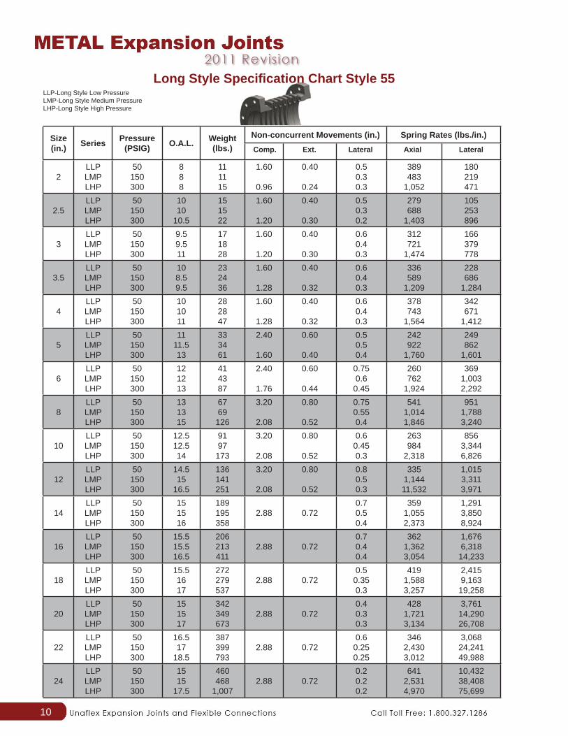
Comp. Ext. Lateral Axial Lateral
LLP-Long Style Low PressureLMP-Long Style Medium PressureLHP-Long Style High Pressure
Long Style Specifi cation Chart Style 55

11
Long Style Specifi cation Chart Style 22
Size(in.) Series Pressure
(PSIG) O.A.L. Weight(lbs.)
Non-concurrent Moments (in.) Spring Rates (lbs.in.)
2LLPLMPLHP
50150300
10266
1.60
0.96
0.40
0.24
0.50.30.3
389483
1,052
180219471
2.5LLPLMPLHP
50150300
10223
1.60
1.20
0.40
0.24
0.50.30.2
279688
1,403
105253896
3LLPLMPLHP
50150300
10343
1.60
1.20
0.40
0.30
0.60.40.3
312721
1,474
166379778
3.5LLPLMPLHP
50150300
10355
1.60
1.28
0.40
0.30
0.60.40.3
336589
1,209
228686
1,284
4LLPLMPLHP
50150300
10445
1.60
1.28
0.40
0.32
0.60.40.3
378743
1,564
342671
1,412
5LLPLMPLHP
50150300
149910
2.40
1.60
0.60
0.40
0.50.50.4
242922
1,760
249862
1,601
6LLPLMPLHP
50150300
14111214
2.40
1.76
0.60
0.44
0.750.60.45
260762
1,924
3691,0032,292
8LLPLMPLHP
50150300
17212323
3.20
2.08
0.80
0.52
0.750.550.4
5411,0141,846
9511,7883,240
10LLPLMPLHP
50150300
17293433
3.20
2.08
0.80
0.52
0.60.450.3
263984
2,318
8563,3446,826
12LLPLMPLHP
50150300
17303440
3.20
2.08
0.80
0.52
0.80.50.3
3351,14411,532
1,0153,3113,971
14LLPLMPLHP
50150300
17253145
2.88 0.720.70.50.4
3591,0552,373
1,2913,8508,924
16LLPLMPLHP
50150300
17293550
2.88 0.720.70.40.4
3621,3623,054
1,6766,318
14,233
18LLPLMPLHP
50150300
17333961
2.88 0.720.50.350.3
4191,5883,257
2,4159,163
19,258
20LLPLMPLHP
50150300
17404670
2.88 0.720.40.30.3
4281,7213,134
3,76114,29026,708
22LLPLMPLHP
50150300
18475783
2.88 0.720.60.250.25
3462,7306,012
3,06824,24149,988
24LLPLMPLHP
50150300
18657197
2.88 0.720.20.20.2
6412,5314,970
10,43238,40875,699
303640
DL 50 18130157173
3.20 0.80 0.2960
1,1601,300
64,500132,000158,000
424648
DL 50 18182200210
3.20 0.80 0.21,1861,2442,400
230,000260,000368,000
505254
DL 25 18220250265
3.20 0.80 0.31,4402,2002,290
45,50080,10090,900
606672
DL 25 18288350380
3.20 0.80 0.22,5802,8403,100
115,000150,500225,000
8486
108DL 15 18
490640660
3.20 0.80 0.153,6104,1504,670
1,500,0001,900,0002,300,000
126132144
DL 15 18730810900
3.20 0.80 0.15,1005,6506,100
2,800,0003,200,0003,600,000
Comp. Ext. Lateral Axial Lateral
LLP-Long Style Low PressureLMP-Long Style Medium PressureLHP-Long Style High Pressure
12
Size(in.) Series Pressure
(PSIG) O.A.L. Weight(lbs.)
Non-concurrent Movements (in.) Spring Rates (lbs.in.)
2LLPLMPLHP
50150300
8101010
1.60
0.96
0.40
0.24
0.50.30.3
389483
1,052
180219471
2.5LLPLMPLHP
50150300
8131314
1.60
1.20
0.40
0.30
0.50.30.2
279688
1,403
105253896
3LLPLMPLHP
50150300
8131414
1.60
1.20
0.40
0.30
0.60.40.3
312721
1,474
166379778
3.5LLPLMPLHP
50150300
8202121
1.60
1.28
0.40
0.32
0.60.40.3
336589
1,209
228686
1,284
4LLPLMPLHP
50150300
8191920
1.60
1.28
0.40
0.32
0.60.40.3
378743
1,564
342671
1,412
5LLPLMPLHP
50150300
11232425
2.40
1.60
0.60
0.40
0.50.50.4
242922
1,760
249862
1,601
6LLPLMPLHP
50150300
12272933
2.40
1.76
0.60
0.44
0.750.6
0.45
260762
1,924
3691,0032,292
8LLPLMPLHP
50150300
12504243
3.20
2.08
0.80
0.52
0.750.550.4
5411,0141,846
9511,7883,240
10LLPLMPLHP
50150300
12485454
3.20
2.08
0.80
0.52
0.60.450.3
263984
2,318
8563,3446,826
12LLPLMPLHP
50150300
12808593
3.20
2.08
0.80
0.52
0.80.50.3
3351,14411,532
1,0153,3113,971
14LLPLMPLHP
50150300
12112118131
2.88 0.720.70.50.4
3591,0552,373
1,2913,8508,924
16LLPLMPLHP
50150300
12142149163
2.88 0.720.70.40.4
3621,3623,054
1,6766,318
14,233
18LLPLMPLHP
50150300
12154161179
2.88 0.720.5
0.350.3
4191,5883,257
2,4159,163
19,258
20LLPLMPLHP
50150300
12191198222
2.88 0.720.40.30.3
4281,7213,134
3,76114,29026,708
22LLPLMPLHP
50150300
13227239263
2.88 0.720.6
0.250.25
3462,7306,012
3,06824,24149,988
24LLPLMPLHP
50150300
13270278307
2.88 0.720.20.20.2
6412,5314,970
10,43238,40875,699
303640
DL 50 13350530626
3.20 0.80 0.2960
1,1601,300
64,500132,000158,000
424648
DL 50 13730806930
3.20 0.80 0.21,1861,2442,400
230,000260,000368,000
505254
DL 25 13980
1,1001,150
3.20 0.80 0.31,4402,2002,290
45,50080,10090,900
606672
DL 25 131,4331,6501,850
3.20 0.80 0.22,5802,8403,100
115,000150,500225,000
8486
108DL 15 13
2,2404,1004,600
3.20 0.80 0.153,6104,1504,670
1,500,0001,900,0002,300,000
126132144
DL 15 135,0505,4006,600
3.20 0.80 0.15,1005,6506,100
2,800,0003,200,0003,600,000
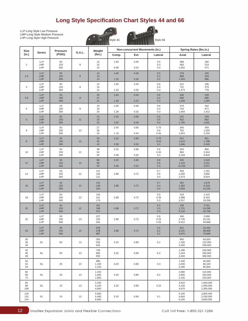
Long Style Specifi cation Chart Styles 44 and 66
Comp. Ext. Lateral Axial Lateral
LLP-Long Style Low PressureLMP-Long Style Medium PressureLHP-Long Style High Pressure
Style 44 Style 66

13
21.53.85.4
162228405264
221810
0.188 2 4 10
0.68751.375
2.18753.8755.6257.375
162228405264
1572518249944830
0.128 2 6
2.51.43.34.6
142228405264
282010
0.157 2 4 12
1.18751.8753.2504.750
6.18757.750
22.528.540.552.564.576.5
805386147764731
0.110 2 8
31.33.14.5
162228405264
321210
0.152 2 4 14
1.18751.8753.3754.8756.3757.875
22.528.540.552.564.576.5
818395149784732
0.102 4 8
41.02.63.7
162228405264
441711
0.151 2 4 16
.93751.43752.5625
3.754.93756.125
132941536577
14356892621368356
0.100 4 8
52.03.04.0
162228405264
502212
0.182 2 4 18
1.3752.0
3.31254.75
6.1257.5625
243042546678
146075730816510370
0.098 4 8
61.53.54.0
162228405264
1006015
0.152 2 6 20
1.31251.8753.125
4.43755.75
7.0625
243042546678
181796139721513492
0.092 4 10
81.53.54.0
162228405264
1208030
0.138 2 6
24
.751.18752.125
3.03.93754.9375
253143556779
42052056795417256173
0.079 4 10
30
.81251.18751.93752.625
3.43754.1875
263244566880
481826961187663423293
0.073 4 10
All data is for reference. Specifi c requirements should be sent to the factory for engineering review
Nominal Size (in.)
LateralMvmt. (in.)
O.A.L.(in.)
LateralSpring Rt(lbs./in.)
AddedMvmt.per 1”add’l
length
Numberof
Rods
ForNipple
Ends Addto Flange
Unit O.A.L.
Nominal Size (in.)
LateralMvmt. (in.)
O.A.L.(in.)
LateralSpring Rt(lbs./in.)
AddedMvmt.per 1”add’l
length
Numberof
Rods
ForNipple
Ends Addto Flange
Unit O.A.L.
• Standard bellows material: A/SA240 321ss• Design Temperature: 500°F• Design Pressure: Up to 150 psig• Standard end connections are 150# drill plate
fl anges (AWWA Class D C207)
• Overall lengths are based on 150# drilling standard plate fl ange thicknesses.
• Overall length may change if other type of fl anges are requested.
Optional liners and covers are available upon request.
Fixed 150# Plate Flanges
Unafl ex® Universal Tied Expansion Joints are capable of absorbing greater lateral movements than standard bellows type expansion joints. Bellows manufactured of 321 Stainless steel. Assembly designed in accordance with EJMA standards. Available with optional liners or covers. Working temperature 500°F Working pressure up to 150 PSI.

14
All technical data subject to change without noticePlease see use, installation, precautions and technical pages
Externally Pressurized-Type EXS Single
Nominal Size (in.)
Pressure (PSIG) at 600
deg FO.A.L. (in.)
Axial Movements Axial Spring Rates (lbs./in.)
2 150300
253442
468
122
19013097
388260194
2.5 150300
253440
468
122
1208072
240160125
3 150300
253440
468
122
1509085
380230190
4 150300
253440
468
122
18511694
540340270
5 150300
253440
468
122
390270210
990670490
6 150300
273542
468
122
470315250
1,180800590
8 150300
273542
468
122
650410325
1,450850710
10 150300
273542
468
122
780490390
1,7401,015870
12 150300
293745
468
122
980610520
2,0201,2131,050
14 150300
293745
468
122
1,9401,220980
3,8962,3701,930
16 150300
293745
468
122
2,1801,3701,080
4,3202,6302,152
Compression Extension 150 PSIG Style 300 PSIG Style

15
All technical data subject to change without noticePlease see use, installation, precautions and technical pages
Externally Pressurized-Type EXD Double
Nominal Size (in.)
Pressure (PSIG) at 600
deg FO.A.L.
Axial Movements (in.) Axial Spring Rates (lbs./in.)
2 150300
406072
81216
244
19013097
388260194
2.5 150300
406072
81216
244
1208072
240160125
3 150300
406072
81216
244
1509085
380230190
4 150300
406072
81216
244
18511694
540340270
5 150300
406072
81216
244
390270210
990670490
6 150300
406072
81216
244
470315250
1,180800590
8 150300
406072
81216
244
650410325
1,450850710
10 150300
406072
81216
244
780490390
1,7401,015870
12 150300
466476
81216
244
980610520
2,0201,2131,050
14 150300
466476
81216
244
1,9401,220980
3,8962,3701,930
16 150300
466476
81216
244
2,1801,3701,080
4,3202,6302,152
Compression Extension 150 PSIG Style 300 PSIG Style

16
Externally Pressurized-Anchor Dimensions
Externally pressurized expansion joints are capable of absorbing large axial movements at higher pressures due to their bellows being pressurized externally. Absorbing large axial movements require high number of convolutions and this in turn increases the bellows instability. By pressurizing the bellows externally, while keeping the unit pressurized internally, bellows column instability problem is eliminated. This type of design also protects the bellows from outside medium, any possible damage during shipping, handling and installation, and from high fl ow velocities.
Standard end connections are 150# drilling plate fl anges (AWWA Class D C207).
Overall lengths are based on 150# drilling standard plate fl ange thicknesses. Overall length may change if other type of fl anges is requested.
For sizes 18” and larger consult factory with application details. Units can be provided with pipe nipples, other types of fl anges, anchor bases and other accessories. Anchors are not designed for pressure forces.
Specifi c requirements should be sent to the factory for engineering review. Spring rates shown are for EACH bellows.
Units come with 3/8” diameter 3000# threaded coupling drains as a standard.
Nom. Dia A B C D E F H Hole
Dia. W1 W2
1.5” 1.5” 2.5” 7” 8” 3/8” 3/8” 5.25” 1/2” 3/16” 3/16”2”-3.5” 2.75” 4” 6.75” 8” 3/8” 3/8” 7.31” 5/8” 3/16” 3/16”4”-6” 4.5” 6.25” 6” 8” 1/2” 1/2” 9.38” 7/8” 1/4” 1/4”
8”-10” 5.25” 8” 9.25” 12” 1/2” 1/2” 12” 1 3/8” 1/4” 1/4”
12”-14” 5.25” 8” 9.25” 12” 3/4” 3/4” 13” 1 3/8” 3/8” 3/8”
16” 5.5” 10” 11.5” 16” 1” 1” 16” 2 1/4” 1/2” 1/2”All technical data subject to change without notice
Please see use, installation, precautions and technical pages

17
Series 5000 BPC Pump Connectors
Standard Operating Specifi cations Max. Operating Pressure: 150 PSI
Max. Operating Temperature: 500°F
Movements: Axial Compression(2”ND to 8”ND): 0.5”
Axial Compression(10”ND to 16”ND):0.75”
Axial Extension (All Sizes):0.25”
Lateral Offset(All Sizes):0.13”
Flanges to mate with ANSI B16.5 150# Flange Drilling.
If fl ow velocity exceeds 25 feet per second, Unafl ex® recommends adding a liner.
Dash Number Nominal I.D. (in.) Overall Length (in.) Flange Thickness (in.)-032 2 3-1/2 5/8
-040 2-1/2 3-1/2 5/8-048 3 4 5/8-056 3-1/2 4 5/8-064 4 4-1/2 5/8-080 5 4-1/2 5/8-096 6 5 5/8-128 8 5 5/8-160 10 6 3/4-192 12 6 3/4-224 14 8 1-256 16 8 1
Series 5000 BPC Bellows Pump Connector AssembliesMetal Bellows Pump Connector Dimensions
All technical data subject to change without noticePlease see use, installation, precautions and technical pages

18
Tube-Flex Engine Exhaust Expansion JointsStyle U-100 Expansion Joints
Unafl ex® “Tube-Flex” Series 7000 Stainless Steel Engine exhaust Expansion Joints are manufactured from a thin-gauge stainless steel tube. This tubular body is formed into corrugations forming a bellows providing a highly fl exible and durable connector for the extremes of exhausting engine gases.
End Connections
Type W Welding Nipples Type T IPT Threaded Nipples Type FP 1/2” Thick plate fl ange (specify
O.D. Bolt Circle, number of Bolt Holes and Bolt Hole diameter).
Type SFP Square plate fl ange (specify outside dimension, Bolt pattern and Bolt hole diameter).
U-100 Style Expansion Joints
Unafl ex® “Tube-Flex” Style U-100 Expansion Joints can absorb longitudinal and lateral movement in one cycle. Opposite ends of the joint can move laterally in opposite directions to complete an expansion cycle. UNAFLEXU-100 joints can be lagged with fi re-proofi ng insulation for fi re protection without affecting fl exibility.
Features
• Can be ordered packed (A) or special packed (S) • Equipped with rigid or fl oating fl anges (optional) • Sizes 4” to 26” I.D.
Applications
• Diesel exhaust steam lines • Water and oil lines; *air intakes • Air service for boilers • Conveying hot liquids
Type W Pipe Size
Type T Max. Operating
Pressure at 70°F
Type FP Standard
Length (in.)
Type SFP PartNumber
1” 40 18 7001
1-1/4” 24 18 7101
1-1/2” 20 18 7201
2” 15 18 7002
3” 8 18 7003
4” 5 18 7004
5” 3 18 7005
6” 3 18 7006
8” 3 18 7008
10” 2 18 7010
12” 2 18 7012

19
“Matchless” Dual Unit Expansion Joints
Unafl ex® can custom design and manufacture various types of expansion joints based on your needs and requirements of the system. Some commonly used non-standard expansion joint types are:
Dual Expansion Joints
Dual expansion joints are used where axial movement is larger than can be absorbed by a single expansion joint. The dual assembly consists of two single bellows connected by an interconnecting weld end. In some cases, this interconnecting weld end has an integral anchor base. The anchor base is designed to withstand the forces required to move either bellows but not for pressure forces. When no anchor base is used, interconnecting weld end must be anchored with standard pipe anchors.
Dual expansion joints can also be used where large amount of movement in any combination (i.e. axial, lateral and angular rotation) is required which cannot be absorbed by a single expansion joint. In this type of application, the interconnecting weld end is not anchored but the remaining system must be properly anchored and guided.
Elbow Pressure Balanced Unit
“MATCHLESS” elbow pressure balanced expansion joints are designed to absorb axial and/or lateral defl ection while continuously restraining pressure force. Balance (out of line) bellows creates an equal and opposite force to the working (in line) bellows.
The typical arrangement (as shown) is to have a balance side and a working side separated by an elbowed mid-section. Tie-rods are used to balance and restrain pressure forces.
Additional Types of Expansion Joints Available
• Gimbal Expansion Joint
• Hinge Expansion Joint
• In-line Pressure Balanced Expansion Joint
• Expansion Joints with Pantograph Linkage
• Expansion Joints with Testable Bellows Two Ply Testable Bellows
• Jacketed Expansion Joints

20
Installation Do’s
• Inspect for damage during shipment, i.e., dents, broken hardware, water marks on carton, etc.
• Store in clean dry area where it will not be exposed to heavy traffi c or damaging environment.
• Use only designated lifting lugs.
• Make the piping system fi t the expansion joint by stretching, compressing, or offsetting the joint to fi t the piping. It may be over stressed when the system is in service.
• It is good practice to leave one fl ange loose until the expansion joint has been fi tted into position. Make necessary adjustment of loose fl ange before welding.
• Install joint with arrow pointing in the direction of fl ow.
• Install single Van Stone liners pointing in the direction of fl ow. Be sure to install a gasket between the liner and Van Stone fl ange as well as between the matting fl ange and liner.
• With telescoping Van Stone line, install the smallest I.D. liner pointing in the direction of fl ow.
• Remove all shipping devices after the installation is complete and before any pressure test of the fully installed system.
• Remove any foreign material that may have become lodged between the convolutions.
• Refer to EJMA Standards for proper guide spacing and anchor recommendations.
Installation Don’ts
• Do not drop or strike carton.
• Do not remove shipping bars until installation is complete.
• Do not use hanger lugs as lifting lugs without approval of manufacturer.
• Do not use chains or any lifting device directly on the bellows or Bellows cover.
• Do not allow weld splatter to hit unprotected bellows. Protect with wet chloride-free asbestos.
• Do not use cleaning agents that contain chlorides.
• Do not use steel wool or wire brushes on bellows.
• Do not force-rotate one end of an expansion joint alignment of bolt holes. Ordinary bellows are not capable of absorbing torque.
• Do not hydrostatic pressure test or evacuate the system before proper installation of all guides and anchors.
• Pipe hangers are not adequate guides.
• Do not exceed a pressure test of 1-1/2 times the rated working pressure of the expansion joint.
• Do not use shipping bars to retain the pressure thrust if tested prior to installation.

21
Single
Double

22
Technical Information
Metal Bellows Expansion Joints are designed to absorb a specifi ed amount of movement by the fl exing of the thin-gauge convolutions. If proper care is not taken during installation, it may reduce the cycle life and the pressure capacity of the expansion joints which could result in a premature failure of the bellows element or damage to the piping system. The following recommendations are included to avoid the most common errors that occur during installation. When in doubt about an installation procedure, contact the manufacturer for clarifi cation before attempting to install the Expansion Joints.
Metal Expansion Joint TypesSingle Expansion Joint: The simplest form of Expansion Joint, of single bellows construction, for the purpose of absorbing any combination of the three basic movements of the pipe section in which it is installed.
Universal Expansion Joint: A Universal Expansion Joint is one containing two bellows joined by a common connector for the purpose of absorbing any combination of the three basic movements: Axial movement, lateral defl ection and angular rotation. Universal Expansion Joints are usually furnished with control rods to distribute the movement between the two bellows of the Expansion Joint and stabilize the common connector. This defi nition does not imply that only a Universal Expansion Joint can absorb combined movement..
Double (Dual) Expansion Joint: A double Expansion Joint consists of two bellows joined by a common connector which is anchored to some rigid part of the installation by means of an anchor base. The anchor base may be attached to the common connector either at installation or at time of manufacture. Each bellows acts as a single Expansion Joint and absorbs the movement of the pipe section in which it is installed independently of the other bellows. Double Expansion Joints should not be confused with Universal Expansion Joints.
Hinged Expansion Joint: A hinged Expansion Joint contains one bellows and is designed to permit angular rotation in one plane only by the use of a pair of pins through hinge plates attached to the Expansion Joint ends. The hinges and hinge pins must be designed to restrain the thrust of the Expansion Joint due to internal pressure and extraneous forces, where applicable. Hinged Expansion Joints should be used in sets of two or three to function properly.
Gimbal Expansion Joint: A gimbal expansion joint is designed to permit angular rotation in any plane by the used of two pairs of hinges affi xed to a common fl oating gimbal ring. The gimbal ring, hinges and pins must be designed to restrain the thrust of the Expansion Joint due to internal pressure and extraneous forces, where applicable.
In-Line Pressure Balanced Expansion Joint: An in-line pressure balanced Expansion Joint is designed to absorb axial and/or lateral movement while restraining the pressure thrust by means of tie devices interconnecting the line bellows with outboard compensating bellows also subjected to line pressure. Each bellows set is designed to absorb the axial movement and usually the line bellows will absorb the lateral defl ection. This type of Expansion Joint is used in a straight run of piping.

23
Metal Expansion Joint Accessories
Internal Sleeve (Liner): A device which minimizes contact between the inner surface of the bellows of an Expansion Joint and the fl uid fl owing through it. These devices have also been referred to as liners or baffl es.
Cover (Shroud): A device used to provide limited protection of the exterior surface of the bellows of an expansion joint from foreign objects or mechanical damage. A cover is sometimes referred to as a shroud.
Testable Bellows Elements: In a two-ply testable bellows, outer ply is a redundant ply that is designed to contain the pressure if the inner ply fails. If the inner ply fails, pressure fl ows to the test port indicating a failure on customer’s instrumentation.
Equalizing Rings/Reinforcing Rings: Devices used on some expansion joints fi tting snugly in the roots of the convolutions. The primary purpose of these devices is to reinforce the bellows against internal pressure. Equalizing rings are made of cast iron, steel, stainless steel or other suitable alloys and are approximately “T” shaped in cross section. Reinforcing or root rings are fabricated from tubing or solid round bars of carbon steel, stainless steel or other suitable alloys.
Control Rods: Devices, usually in the form of rods or bars, attached to the Expansion Joint assembly whose primary function is to distribute the movement between the two bellows of a Universal Expansion Joint. Control rods are not designed to restrain bellows pressure thrust.
Limit Rods: Devices, usually in the form of rods or bars, attached to the expansion joint assembly whose primary function is to restrict the bellows movement range (axial, lateral, and angular) during normal operation. In the event of a main anchor failure, they are designed to prevent bellows over-extension or over-compression while restraining the full pressure loading and dynamic forces generated by the anchor failure.
Tie Rods: Devices, usually in the form of rods or bars attached to the Expansion Joint assembly whose primary function is to continuously restrain the full bellows pressure thrust during normal operation while permitting only lateral defl ection. Angular rotation can be accommodated only if two tie rods are used and 90 degrees opposed to the direction of rotation.
Purge Connections: Purge connections, where required, are usually installed at the sealed end of each internal sleeve of an Expansion Joint for the purpose of injecting a liquid or gas between the bellows and the internal sleeve to keep the area clear of erosive and corrosive media and/or solids that could pack the convolutions. Purging may be continuous, intermittent or just on start-up or shut down, as required. These are sometimes called aeration connections..
Pantograph Linkages: A scissors-like device. A special form of control rod attached to the Expansion Joint assembly whose primary function is to positively distribute the movement equally between the two bellows of the universal joint throughout its full range of movement. Pantograph linkages, like control rods, are not designed to restrain pressure thrust.

24
Key Concepts
Bellows: Flexible element of an expansion joint consisting of one or more convolutions and the end tangents.
Convolution: Smallest fl exible unit of a bellows. Total movement capacity and fl exibility of a bellows is proportional to the number of convolutions.
Pressure Thrust: Pressure thrust is created by the installation of a fl exible unit, such as an expansion joint, into a rigid piping system which is under pressure. Pressure thrust force is a function of the system pressure and mean diameter of the bellows. In cases of internal or positive pressure, bellows are forced to extend in length while the opposite is observed in cases of external or negative pressure. This force is transmitted from the ends of the expansion joint along the pipe.
Shipping Bars: Rigid support devices installed on expansion joint to maintain the overall length of the assembly for shipment and installation. These devices may also be used to pre-compress, pre-extend or laterally offset the bellows. They should not be used to resist pressure thrust during testing.
Movements, Cycle Life, Anchoring and Guiding Axial Movement
Axial Compression: The dimensional shortening of an Expansion Joint along its longitudinal axis. Axial compression has been referred to as axial movement, traverse or compression.
Lateral Movement: This relative displacement of the two ends of an Expansion Joint perpendicular to its longitudinal axis. This has been referred to as lateral offset, lateral movement, parallel misalignment, direct shear or transverse movement.
Angular Movement: This displacement of the longitudinal axis of the Expansion Joint from its initial straight line position into a circular arc. Angular rotation is occasionally referred to as “rotational movement.” This is not torsional rotation.
Angular Extension: The dimensional lengthening of an Expansion Joint along its longitudinal axis. Axial extension has been referred to as axial movement, traverse, elongation or extension.

25
Cycle Life
The cycle life of an expansion joint is the number of stress cycles endured at operating conditions. A stress cycle if defi ned as one complete movement of the expansion joint from initial to extreme position and return.
Main Anchor: A main anchor is one which must withstand the full bellows thrust due to pressure, fl ow, spring forces and all other piping loads.
A main anchor base for connection to the anchor structure can be furnished as an integral part of a single or double Expansion Joint, if desired. The Expansion Joint manufacturer must be advised of the magnitude and direction of all forces and moments which will be imposed upon the anchor base, so that it can be adequately designed to suit the specifi c application.
Intermediate Anchors: An intermediate anchor is one which must withstand the bellows thrust due to fl ow, spring forces, and all other piping loads, but not the thrust due to pressure.
An intermediate anchor base for connection to the anchor structure can be furnished as an integral part of a single or double Expansion Joint, if desired. The Expansion Joint manufacturer must be advised of the magnitude and direction of all forces and moments which will be imposed upon the anchor base, so that it can be adequately designed to suit the specifi c application.
Pipe Guides and Supports: Correct alignment of the pipe adjoining an expansion joint is important to its proper function. Maximum service from expansion joints will be obtained only when the pipeline has recommended number of guides and is anchored and supported in accordance with good piping practice. When locating pipe guides for applications involving axial movement only, it is generally recommended that the expansion joint be located near an anchor and that the fi rst guide be located a maximum of 4 pipe diameters away from the expansion joint. For more information please see EJMA guidelines.

26
Pressure Thrust
When a bellows is pressurized, it reacts causing a load equal to its effective area X working pressure along its longitudinal axis. These loads must be considered when designing the system arrangement and appropriate anchors.
2 6.3 18 290 52 2,2902-1/2 9.6 20 354 54 2,460
3 12.0 22 426 60 3,0254 20 24 500 66 3,6355 30.0 30 775 72 4,3006 43.0 36 1,090 84 5,8008 72.0 40 1,350 96 7,55010 110 42 1,470 108 9,51012 150 46 1,775 126 13,20014 180 48 1,940 132 14,11016 234 50 2,125 144 16,750
Size Eff. Area sq. in.
Size Eff. Area sq. in.
Size Eff. Area sq. in.
