eecs 452 lab 2—basic dsp using the c5515 ezdsp … 452 lab 2—basic dsp using the c5515 ezdsp...
TRANSCRIPT

EECS 452 Lab 2—Basic DSP Using the C5515 eZDSP Stick
The purposes of this lab are to:
• Provide an platform for using direct digital synthesis (DDS) • Provide an experience of basic FIR design and implementation for a DSP. • Learn how to measure CPU utilization and how to judge if you are meeting “real time”
constraints. • Reinforce the introduction to embedded systems and memory-mapped I/O devices from the
previous lab
1. Lab Overview and Background Material In the first part of this lab, you will explore a better way to implement DDS. The way we generated
waveforms in the previous lab was slow and memory expensive. In this lab you will implement an algorithm which is faster, more memory efficient, and allows for dynamic frequency scaling.
In the second part of this lab, you will be designing and implementing an FIR filter. For the pre-lab, you will use Matlab’s fdatool to find the coefficients for this filter. We will use this tool because finding more than five or ten coefficients for an FIR filter by hand would be very time consuming, but we will be making a sixty tap filter (filter with sixty coefficients). Understanding how to use fdatool to design filters is the easy part, you will still need to implement the filter which is no easy task; people get paid to do nothing but that. You will explore the various means of doing an array-based implementation of an FIR filter, and understand the trade-offs associated with them.
2. Pre-lab The pre-lab will prepare you for both the DDS and filter design parts. In this pre-lab you will:
• Get the coefficients for an order 60 FIR filter using “fdatool” in Matlab. • Read and understand DDS code. • Examine and designing a very simple anti-imaging filter for use with both the FIR filter and
the DDS outputs.
FIR filter We are going to use Matlab to generate an FIR filter because it has the tools to make a filter with
hundreds of taps in seconds, where doing by hand might take hours. One issue with our documenting this process is that Matlab literally changes once or twice a year. This means that the “look and feel” of the tools you are using may be different than shown below. It also means that different locations may be running different versions.
VF14.0, 9/5/2014 5:12 PM

EECS 452 Lab 2— Basic DSP Using the C5515 eZDSP Stick Page 2 of 16
With these caveats in mind, let’s start the task of designing an FIR filter in Matlab. Open up Matlab on your computer. Type the command “fdatool” into the command window. You should get the following window on your screen.
From here, you can design an FIR or IIR filter via an interactive GUI. We are going to arbitrarily make
a low-pass filter first. Go to the left hand side of the window and select “lowpass” in the “Response Type” section, which we have circled it in red below. Make sure the bubble is green and the text field reads “Lowpass”.
Now you could let Matlab
decide how large to make your filter by selecting the “Minimum order” option in the Filter Order section of the window, just right of the Response Type window. However we will specify the order. To do this fill in the bubble next to Specify order in the Filter Order section we circled green below, and type 60 into the field next to it.
Now we have to choose the
transition band of this filter. To do this we will manipulate the
values in the “Frequency Specifications” section. We will leave the “Fs” field alone because we will be sampling at 48kHz, which is the default. But we will change what Fpass and Fstop are. Change Fpass to 9000 and Fstop to 12000 (circled in blue). Press the “Design Filter” button on the bottom of the window and Matlab will calculate the filter coefficients.

EECS 452 Lab 2— Basic DSP Using the C5515 eZDSP Stick Page 3 of 16
Now that Matlab has generated our FIR filter, we need to export the coefficients so we can use them in a C program. Because it is so common to want to implement filters in C, Matlab has a handy mechanism for generating the output as a C-header file. Select “Targets” and then “Generate C header …” as circled in red below.1
You should then get the following window. Please change the “Numerator:” field to “LP” and the
“Numerator length:” field to “LPL”. These are just the variable names Matlab will use. Later in the lab we will be adding more filters to our processor, so we’ve chosen these names for the values associated with the low pass (LP) filter. You now need to export these coefficients as sixteen-bit signed integers. To do this, select the “Export as:” option at the bottom on the window. Then click the down arrow and select Signed sixteen bit integer.
Now click the “Generate” button to
complete the process. You will be asked where you want to put your new file. You may want to make a new folder on your desktop to accommodate these header files. Rename the file to low_pass.h and click Save.
The code that Matlab generates needs
to be modified a bit. You need to delete the #include near the top of the file. Also change the “const int LPL = 61;” into a “#define LPL 61” and the “const int_16” next to LP on the next line into “Int16”. Save your changes. Do not add a
semicolon after definitions. They will throw compiler errors. Q1. Print the file you generated (and modified) as described above. Q2. The default structure of the FIR filter is “Direct-Form FIR”
a. How is this different from the Transposed-Form? b. Draw the Direct-Form and Transposed-Form FIR. What do you think the advantage of
each structure is?
1 With this scheme your header file will likely contain a warning about rounding issues for the coefficients. For the most part, the rounding issues aren’t going to be relevant for FIR filters or even most IIR filters. But they can cause instability in IIR filters that have poles near or on the unit circle as the rounding could push them outside of the unit circle.

EECS 452 Lab 2— Basic DSP Using the C5515 eZDSP Stick Page 4 of 16
Q3. Answer the following questions assuming you have the FIR filter you just created using Matlab. a. What is the expected group delay? b. What is the expected phase shift in a 1 KHz input? c. What is the lowest frequency where you would expect to see a 180 degree phase shift?
TI’s DSPLIB FIR filter Now we’ll take a look at the FIR filter supplied by TI. It is a highly-optimized assembly language
implementation. You can read about it in the C55x DSPLIB documentation. It is document spru422j (which can be found with a web search). The documentation starts on page 4-46.
Q4. In your own words, explain the role of each of the arguments to fir(). Figure 4-16 in the C55x DSPLIB documentation describing the dbuffer of the fir() function is wrong. Make sure you understand why it is wrong. The corrected one is shown below.
Q5. Redraw the figure assuming index= 4.
entry index = 2 lowest memory address
x(j-nh+2)
x(j-nh+1) oldest x( ) entry x(j-nh) newest x( ) entry x(j-0)
x(j-1)
x(j-2)
x(j-nh+5)
x(j-nh+4) highest memory address
x(j-nh+3)
Q6. Let’s suppose we have a buffer in to store audio samples, and this buffer has 256 entries. One
way we could index the buffer is to use if statements and reset the index to 0 if it exceeds 255. How could we do this using bit-masking instead? Right one or two lines of code to accomplish this.
DDS Q7. Read the in-lab section associated with DDS. Consider the figure found in that section with the
caption “DDS block diagram”. If the register were 16 bits but only the top 6 bits were used to index the sine table, what would be the output frequency of the generated sine wave if fs were 48 KHz and FTV=2? Show your work.

EECS 452 Lab 2— Basic DSP Using the C5515 eZDSP Stick Page 5 of 16
Q8. If the sine table we are using doesn’t have 64 entries and instead has only 48 entries, we can’t use all the possible values of the register. Given that, what would be the output frequency of the generated sine wave if fs were 48 KHz and FTV=2? Again, show your work.
Analog filter and other background The AIC3204 doesn’t come with an analog filter because it outputs information meant for stereos or
headphones which act as their own low-pass filters. But we are going to need to make our own low-pass filter for use as an anti-imaging (or reconstruction) filter.2
Q9. Design a first-order passive low-pass filter. Assume you have only a 10k Ohm resistor and you want the “3dB-down” frequency to be 30 kHz. Assume you have any capacitor value you need.
a. Draw a picture of the circuit and label the values of the components.3 b. If you were to use a 10 kHz unit-amplitude sine wave as an input, what would you
expect the magnitude of the output to be? c. As above but for a 30 kHz sine wave? A 100 kHz sine wave?
Q10. Consider a stereo tip-ring-sleeve (TRS) connector. Draw a diagram showing what each part of
the connector is generally used for. Cite your source(s).
2 http://en.wikipedia.org/wiki/Reconstruction_filter provides an overview/reminder of what this is. 3 http://en.wikipedia.org/wiki/RC_time_constant and http://www.electronics-tutorials.ws/filter/filter_2.html
may prove useful if you’ve forgotten how to do this kind of a thing.

EECS 452 Lab 2— Basic DSP Using the C5515 eZDSP Stick Page 6 of 16
3. In Lab: As noted above, this lab has two parts, the DDS material and the FIR filter implementation. In
addition, you will need to build a simple analog low-pass filter.
Using Starting_Point.zip Unlike in lab 1, we will have you start by copying a “starting point” Code Composer Studio project
from the course website. If you set things up correctly in lab 1, you should find a file named “Starting_point.zip” in your workspace inside the C5515_Support_Files. This should correctly set your paths and take care of all the other set-up stuff done in part 1 of the in lab portion of lab 1. If you encounter problems with this starting point you can instead redo the work you did in lab 1 or copy your “blinky” project and start from there. All three mechanisms can be made to work for you, but we recommend using the provided starting point.
Find the “Starting_Point.zip” file (do not unzip) in the C5515_support_files. In CCS go to
“FileImport…” select “Code Composer Studio” “Existing CCS Eclipse Projects” and click “Next >”. Now next to the “Select archive file” option browse for the Starting_Point.zip file. Click “Finish.”
Rename the project to whatever it is you want it to be called and start coding from there.
Part 1: Analog Filter and other background Build the analog filter you designed in the pre-lab. Obviously you’ll not be able get an exact value
for your capacitor, so find the closest value you can. You may want to have your GSI check your circuit. Q1. What value capacitor did you choose? Q2. Input unit-amplitude 10, 30, and 100 KHz sine waves. For each input, list the output
amplitude. How well does this match with your pre-lab answers?
Part 2: Direct Digital Synthesis (DDS) Recall that in lab 1 you wrote code which generated sinusoids of certain frequencies. Now we are
going to do true DDS (Direct Digital Synthesis). The idea is expressed with the following graphic.
Figure 1: DDS block diagram
Using DDS to create a sinusoid consists of three steps. First a frequency tuning value (FTV) is
selected. This is determined by the desired frequency of the sinusoid and will be held constant until we want to change frequency. Second, on each rising edge of the clock (which has a frequency of fs) the
EECS 452 Lab 2— Basic DSP Using the C5515 eZDSP Stick Page 7 of 16
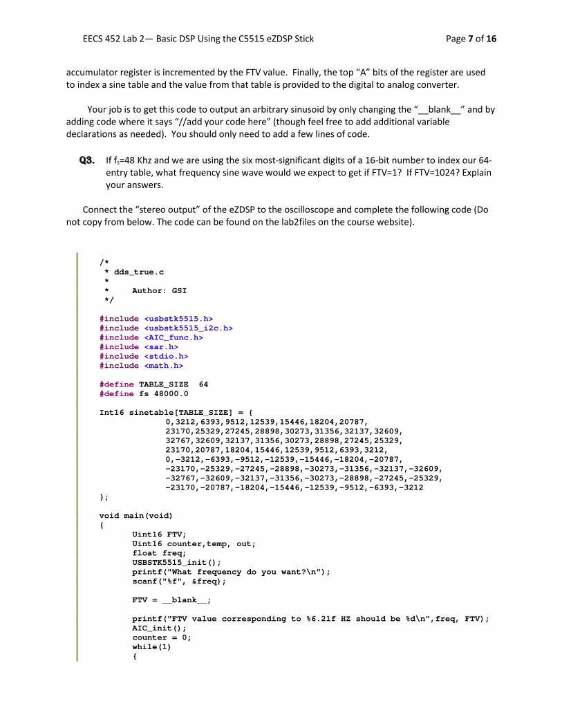
accumulator register is incremented by the FTV value. Finally, the top “A” bits of the register are used to index a sine table and the value from that table is provided to the digital to analog converter.
Your job is to get this code to output an arbitrary sinusoid by only changing the “__blank__” and by
adding code where it says “//add your code here” (though feel free to add additional variable declarations as needed). You should only need to add a few lines of code.
Q3. If fs=48 Khz and we are using the six most-significant digits of a 16-bit number to index our 64-
entry table, what frequency sine wave would we expect to get if FTV=1? If FTV=1024? Explain your answers.
Connect the “stereo output” of the eZDSP to the oscilloscope and complete the following code (Do
not copy from below. The code can be found on the lab2files on the course website).
/* * dds_true.c * * Author: GSI */ #include <usbstk5515.h> #include <usbstk5515_i2c.h> #include <AIC_func.h> #include <sar.h> #include <stdio.h> #include <math.h> #define TABLE_SIZE 64 #define fs 48000.0 Int16 sinetable[TABLE_SIZE] = { 0,3212,6393,9512,12539,15446,18204,20787, 23170,25329,27245,28898,30273,31356,32137,32609, 32767,32609,32137,31356,30273,28898,27245,25329, 23170,20787,18204,15446,12539,9512,6393,3212, 0,-3212,-6393,-9512,-12539,-15446,-18204,-20787, -23170,-25329,-27245,-28898,-30273,-31356,-32137,-32609, -32767,-32609,-32137,-31356,-30273,-28898,-27245,-25329, -23170,-20787,-18204,-15446,-12539,-9512,-6393,-3212 }; void main(void) { Uint16 FTV; Uint16 counter,temp, out; float freq; USBSTK5515_init(); printf("What frequency do you want?\n"); scanf("%f", &freq); FTV = __blank__; printf("FTV value corresponding to %6.2lf HZ should be %d\n",freq, FTV); AIC_init(); counter = 0; while(1) {
EECS 452 Lab 2— Basic DSP Using the C5515 eZDSP Stick Page 8 of 16
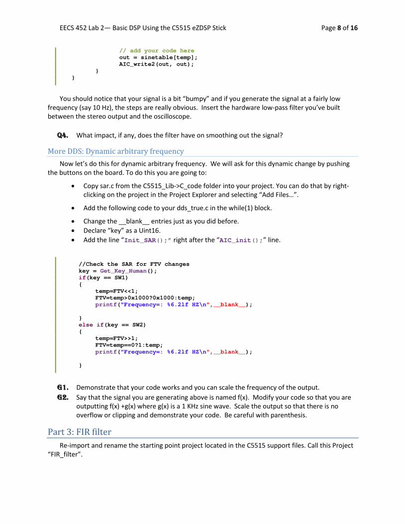
// add your code here out = sinetable[temp]; AIC_write2(out, out); } }
You should notice that your signal is a bit “bumpy” and if you generate the signal at a fairly low
frequency (say 10 Hz), the steps are really obvious. Insert the hardware low-pass filter you’ve built between the stereo output and the oscilloscope.
Q4. What impact, if any, does the filter have on smoothing out the signal?
More DDS: Dynamic arbitrary frequency Now let’s do this for dynamic arbitrary frequency. We will ask for this dynamic change by pushing
the buttons on the board. To do this you are going to:
• Copy sar.c from the C5515_Lib->C_code folder into your project. You can do that by right-clicking on the project in the Project Explorer and selecting “Add Files…”.
• Add the following code to your dds_true.c in the while(1) block.
• Change the __blank__ entries just as you did before. • Declare “key” as a Uint16. • Add the line “Init_SAR();” right after the “AIC_init();” line.
//Check the SAR for FTV changes key = Get_Key_Human(); if(key == SW1) { temp=FTV<<1; FTV=temp>0x1000?0x1000:temp; printf("Frequency=: %6.2lf HZ\n",__blank__); } else if(key == SW2) { temp=FTV>>1; FTV=temp==0?1:temp; printf("Frequency=: %6.2lf HZ\n",__blank__); }
G1. Demonstrate that your code works and you can scale the frequency of the output. G2. Say that the signal you are generating above is named f(x). Modify your code so that you are
outputting f(x) +g(x) where g(x) is a 1 KHz sine wave. Scale the output so that there is no overflow or clipping and demonstrate your code. Be careful with parenthesis.
Part 3: FIR filter Re-import and rename the starting point project located in the C5515 support files. Call this Project
“FIR_filter”.

EECS 452 Lab 2— Basic DSP Using the C5515 eZDSP Stick Page 9 of 16
Hook up your USBSTK5515’s “stereo in” to the function generator. Be sure that the function generator’s output is going into the red cable in the stereo adapter cable; also be sure the function generator has its output set to “High Z” (it’s under “utility” then “output setup” on the function generator). And be sure to hook up the red cable of the stereo out of the USBSTK to the oscilloscope if it isn’t already because we will verify the functionality of our filter with them. Now after that is completed add fir_filter.c (found in the lab2files on ctools) to your project. Add to project the file that houses the FIR low-pass filter you made in the pre-lab and rename that file to be “low_pass.h”.
/* * fir_filter.c * * Author: GSI */ #include <usbstk5515.h> #include <usbstk5515_i2c.h> #include <AIC_func.h> #include <stdio.h> #include "low_pass.h" #define ASIZE 61 #define TCR0 *((ioport volatile Uint16 *)0x1810) #define TIMCNT1_0 *((ioport volatile Uint16 *)0x1814) #define TIME_START 0x8001 #define TIME_STOP 0x8000 Int16 in [ASIZE]; Uint16 delta_time; Int16 FIR(Uint16 i) { Int32 sum; Uint16 j; Uint32 index; sum=0; //The actual filter work for(j=0; j<LPL; j++) { if(i>=j) index = i - j; else index = ASIZE + i - j; sum += (Int32)in[index] * (Int32)LP[j]; } sum = sum + 0x00004000; // So we round rather than truncate. return (Int16) (sum >> 15); // Conversion from 32 Q30 to 16 Q15. } void main(void)
EECS 452 Lab 2— Basic DSP Using the C5515 eZDSP Stick Page 10 of 16
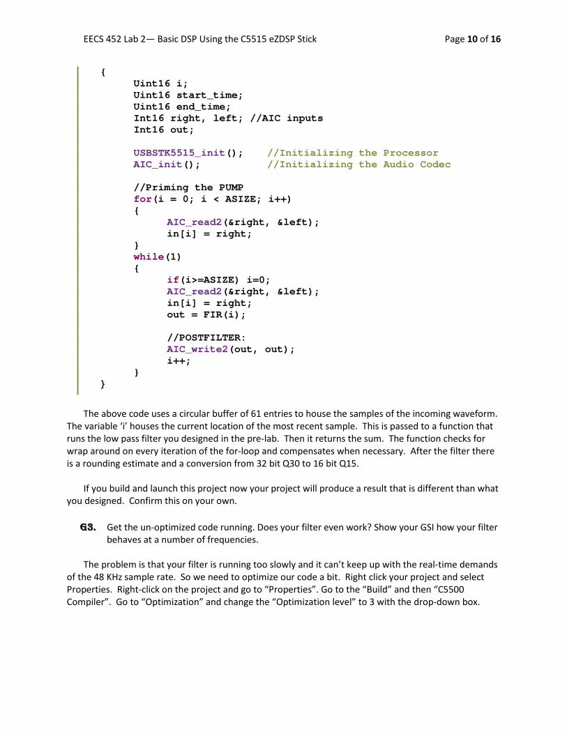
{ Uint16 i; Uint16 start_time; Uint16 end_time; Int16 right, left; //AIC inputs Int16 out; USBSTK5515_init(); //Initializing the Processor AIC_init(); //Initializing the Audio Codec //Priming the PUMP for(i = 0; i < ASIZE; i++) { AIC_read2(&right, &left); in[i] = right; } while(1) { if(i>=ASIZE) i=0; AIC_read2(&right, &left); in[i] = right; out = FIR(i); //POSTFILTER: AIC_write2(out, out); i++; } }
The above code uses a circular buffer of 61 entries to house the samples of the incoming waveform.
The variable ‘i’ houses the current location of the most recent sample. This is passed to a function that runs the low pass filter you designed in the pre-lab. Then it returns the sum. The function checks for wrap around on every iteration of the for-loop and compensates when necessary. After the filter there is a rounding estimate and a conversion from 32 bit Q30 to 16 bit Q15.
If you build and launch this project now your project will produce a result that is different than what
you designed. Confirm this on your own. G3. Get the un-optimized code running. Does your filter even work? Show your GSI how your filter
behaves at a number of frequencies.
The problem is that your filter is running too slowly and it can’t keep up with the real-time demands of the 48 KHz sample rate. So we need to optimize our code a bit. Right click your project and select Properties. Right-click on the project and go to “Properties”. Go to the “Build” and then “C5500 Compiler”. Go to “Optimization” and change the “Optimization level” to 3 with the drop-down box.
EECS 452 Lab 2— Basic DSP Using the C5515 eZDSP Stick Page 11 of 16
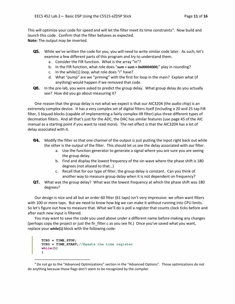
This will optimize your code for speed and will let the filter meet its time constraints4. Now build and launch this code. Confirm that the filter behaves as expected. Note: The output may be inverted.
Q5. While we’ve written the code for you, you will need to write similar code later. As such, let’s examine a few different parts of this program and try to understand them.
a. Consider the FIR function. What is the array “in”? b. In the FIR function, what role does “sum = sum + 0x00004000;” play in rounding? c. In the while(1) loop, what role does “i” have? d. What “pump” are we “priming” with the first for loop in the main? Explain what (if
anything) would happen if we removed that code. Q6. In the pre-lab, you were asked to predict the group delay. What group delay do you actually
see? How did you go about measuring it? One reason that the group delay is not what we expect is that our AIC3204 (the audio chip) is an
extremely complex device. It has a very complex set of digital filters itself (including a 20 and 25 tap FIR filter, 5 biquad blocks (capable of implementing a fairly complex IIR filter) plus three different types of decimation filters. And all that’s just for the ADC, the DAC has similar features (use page 45 of the AIC manual as a starting point if you want to read more). The net effect is that the AIC3204 has a lot of delay associated with it.
G4. Modify the filter so that one channel of the output is just putting the input right back out while
the other is the output of the filter. This should let us see the delay associated with our filter. a. Use the function generator to generate a signal where you are sure you are seeing
the group delay. b. Find and display the lowest frequency of the sin wave where the phase shift is 180
degrees (not aliased to that…) c. Recall that for our type of filter, the group delay is constant. Can you think of
another way to measure group delay when it is not dependent on frequency? Q7. What was the group delay? What was the lowest frequency at which the phase shift was 180
degrees?
Our design is nice and all but an order 60 filter (61 taps) isn’t very impressive: we often want filters with 100 or more taps. But we need to know how big we can make it without running into CPU limits. So let’s figure out how to measure that. What we’ll do is poll a register that counts clock ticks before and after each new input is filtered.
You may want to save the code you used above under a different name before making any changes (perhaps copy the project or just the fir_filter.c as you see fit.) Once you’ve saved what you want, replace your while(1) block with the following code:
TCR0 = TIME_STOP; TCR0 = TIME_START;//Resets the time register while(1) {
4 Do not go to the “Advanced Optimizations” section in the “Advanced Options”. Those optimizations do not do anything because those flags don’t seem to be recognized by the compiler.

EECS 452 Lab 2— Basic DSP Using the C5515 eZDSP Stick Page 12 of 16
if(i>=ASIZE) i=0; AIC_read2(&right, &left); in[i] = right; //Measuring the time of the filter chosen start_time = TIMCNT1_0; out = FIR(i); end_time = TIMCNT1_0; delta_time = (start_time-end_time) << 1; //Take care of the prescalar factor //POSTFILTER: AIC_write2(out, out); i++; }
Here we are using a built-in counter which counts down and has a prescalar5 of two. That means
that the start time has a higher value than the end time and that every one count of the counter is two clock ticks.
Q8. Answer the following questions on filter timing. a. If we have a 100MHz processor and we sample at about 50kHz (makes the math easier)
what is the maximum number of cycles that our filter can use for each input before we need to worry about not being able to meet our real-time constraints?
b. How many cycles does our current filter take? To measure this, click the expressions tab, which is circled red in the following graphic and type into the text field delta_time. Launch the program then pause it to read delta_time. You can also toggle a break point at the beginning or end of a loop you’re interested in so you’re not randomly guessing where you’ve stopped the code.
c. Given the above, how large do you think we could make the filter before we started to run out of CPU time? (Hint: Try to half/double the length of the filter and see whether you half/double the CPU cycles, roughly. Then you have to consider the cycles taken by AIC_read2/AIC_write2.)
That doesn’t seem very useful. What if we did indexing a bit differently? How else could we index
into the array of samples? We could use the mod function. Let’s try it and see if it helps. Replace the current if else statements in the “for loop” of our low pass filter with:
5 A prescalar divides the clock before counting. In this case it divides the system clock’s frequency by 2. See http://en.wikipedia.org/wiki/Prescaler
EECS 452 Lab 2— Basic DSP Using the C5515 eZDSP Stick Page 13 of 16
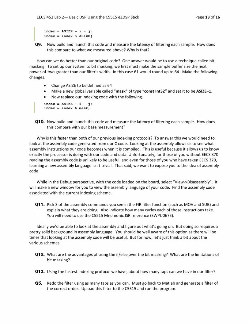
index = ASIZE + i - j; index = index % ASIZE;
Q9. Now build and launch this code and measure the latency of filtering each sample. How does this compare to what we measured above? Why is that?
How can we do better than our original code? One answer would be to use a technique called bit masking. To set up our system to bit masking, we first must make the sample buffer size the next power-of-two greater than our filter’s width. In this case 61 would round up to 64. Make the following changes:
• Change ASIZE to be defined as 64 • Make a new global variable called “mask” of type “const Int32” and set it to be ASIZE–1. • Now replace our indexing code with the following. index = ASIZE + i - j; index = index & mask;
Q10. Now build and launch this code and measure the latency of filtering each sample. How does
this compare with our base measurement? Why is this faster than both of our previous indexing protocols? To answer this we would need to
look at the assembly code generated from our C code. Looking at the assembly allows us to see what assembly instructions our code becomes when it is compiled. This is useful because it allows us to know exactly the processor is doing with our code and data. Unfortunately, for those of you without EECS 370 reading the assembly code is unlikely to be useful, and even for those of you who have taken EECS 370, learning a new assembly language isn’t trivial. That said, we want to expose you to the idea of assembly code.
While in the Debug perspective, with the code loaded on the board, select “View->Disassembly”. It
will make a new window for you to view the assembly language of your code. Find the assembly code associated with the current indexing scheme.
Q11. Pick 3 of the assembly commands you see in the FIR filter function (such as MOV and SUB) and
explain what they are doing. Also indicate how many cycles each of those instructions take. You will need to use the C5515 Mnemonic ISR reference (SWPU067E).
Ideally we’d be able to look at the assembly and figure out what’s going on. But doing so requires a pretty solid background in assembly language. You should be well aware of this option as there will be times that looking at the assembly code will be useful. But for now, let’s just think a bit about the various schemes.
Q12. What are the advantages of using the if/else over the bit masking? What are the limitations of
bit masking? Q13. Using the fastest indexing protocol we have, about how many taps can we have in our filter?
G5. Redo the filter using as many taps as you can. Must go back to Matlab and generate a filter of
the correct order. Upload this filter to the C5515 and run the program.

EECS 452 Lab 2— Basic DSP Using the C5515 eZDSP Stick Page 14 of 16
This still isn’t very impressive. It turns out that if we were to write this code in assembly and
optimize it, we could do a lot better. Thankfully, TI provides a DSP library that does just this for many common types of filters and we will try the FIR filter function in the next section.
Q14. What is the CPU latency per sample with your new filter?
G6. Rewrite the code of your order 60 FIR filter using Transposed-Form FIR. Have your GSI check
both the code and the functionality.
Part 4: TI’s FIR filter Import the Starting_point project and rename it to TI_FIR. Be sure optimization is set to 3.
Q15. Look at the libraries that are included in the project (right click on project in project window, go to “Properties”. Then select “Build C5500 Linker”). Look under the “File Search Path”. What library do you think is associated with TI’s DSPlib?
Use Matlab to generate a low pass filter that has a Fpass of 2000 and Fstop of 3000 with Fs=48000.
Instead of specifying an order, choose the “Minimum order” option. Generate a C header file and modify it as needed so you can use the coefficients with the fir() function. Name the coefficients file ”low_pass1.h”. Make sure your header file declarations are consistent with the variables in TI_FIR.c. Make sure the header file is located in one of CCS’s search paths.
You will find the code below on the course website in the lab2_files named “TI_FIR.c”. Note that the header for the DSPlib functions is “Dsplib.h”. Your main() should be as follows…
#include <usbstk5515.h> #include <stdio.h> #include <Dsplib.h> #include <AIC_func.h> #include "low_pass1.h" void main() { Int16 x[1]; Int16 dbuffer[LPL+2]={0}; Int16 r[1]; Int16 left; USBSTK5515_init(); //Initializing the Processor AIC_init(); //Initializing the Audio Codec while(1) { AIC_read2(x, &left); fir( x, // input LP, // coef r, // output dbuffer, // Z-1 blocks and more 1, // number to process

EECS 452 Lab 2— Basic DSP Using the C5515 eZDSP Stick Page 15 of 16
LPL // number of parameters ); AIC_write2(r[0],r[0]); } }
Connect things so that the function generator’s output is being filtered by the C5515 then displayed
on the oscilloscope. Have both the filter input and output displayed on the oscilloscope. Run the program. Instrument your code so that you can display how many cycles the function takes (similar to how we did it in part 3.)
Q16. a. How many taps are there in your FIR filter? b. How many cycles did the fir() function take to process a single input?
Do the same thing but try Fstop=2200. Now fdatool should design a 500+ order filter.
Q17.
a. How many taps are there in your FIR filter? b. How many cycles did the fir() function take to process a single input? c. Assuming there is some constant overhead associated with calling the fir() function and
that runtime is otherwise linear, how many taps could you process in real-time? Show your work.
d. How does this compare to the code you wrote in the previous part? G7. Demonstrate your 500+ tap filter to the GSI and show how you’ve instrumented the code to get
the runtime information. Be sure the oscilloscope is set up to view both the input and output of your 500+ tap filter. Set the
function generator to sweep from 500Hz to 3.5kHz. Observe the amplitude of the output (relative to input) as a function of frequency.
G8. Demonstrate the sweeping frequency response to your GSI
Q18. a. Sketch (roughly) the frequency response of your 500+ tap filter in the swept range. b. How does your sketch compare to the frequency response that fdatool gave you when
you designed the filter? Note: in fdatool, right click on the Y-axis (where it says Magnitude) and chose the linear version (not dB). You can also zoom the X-axis to the same swept range for comparison.
EECS 452 Lab 2— Basic DSP Using the C5515 eZDSP Stick Page 16 of 16
4. Post Lab: Q1. One hardware construct that is commonly added to DSPs, but not to “standard” processors, is
“circular buffers”. See http://www.dspguide.com/ch28/2.htm for example. a. Explain why they would be helpful here. b. The C5515 supports circular buffering. Look at TI’s manual named “spru371f.pdf” and
read section 6.11. Explain, in your own words, how they work.
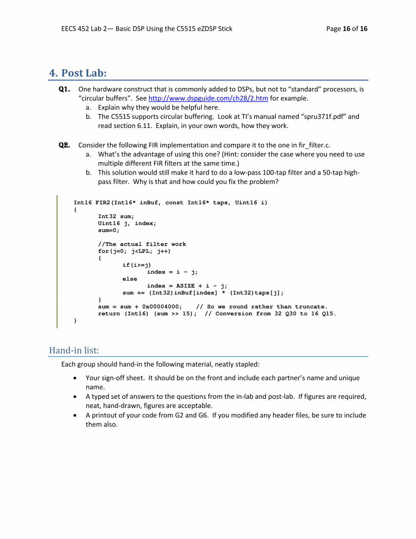
Q2. Consider the following FIR implementation and compare it to the one in fir_filter.c. a. What’s the advantage of using this one? (Hint: consider the case where you need to use
multiple different FIR filters at the same time.) b. This solution would still make it hard to do a low-pass 100-tap filter and a 50-tap high-
pass filter. Why is that and how could you fix the problem?
Int16 FIR2(Int16* inBuf, const Int16* taps, Uint16 i) { Int32 sum; Uint16 j, index; sum=0; //The actual filter work for(j=0; j<LPL; j++) { if(i>=j) index = i - j; else index = ASIZE + i - j; sum += (Int32)inBuf[index] * (Int32)taps[j]; } sum = sum + 0x00004000; // So we round rather than truncate. return (Int16) (sum >> 15); // Conversion from 32 Q30 to 16 Q15. }
Hand-in list: Each group should hand-in the following material, neatly stapled:
• Your sign-off sheet. It should be on the front and include each partner’s name and unique name.
• A typed set of answers to the questions from the in-lab and post-lab. If figures are required, neat, hand-drawn, figures are acceptable.
• A printout of your code from G2 and G6. If you modified any header files, be sure to include them also.