ee382v-ics: system-on-a-chip (soc) designjaa/soc/lectures/8-2.pdf · ee382v-ics: system-on-a-chip...
TRANSCRIPT

EE382V-ICS: System-on-Chip (SoC) Design
Lecture 8
© 2010 A. Gerstlauer 1
EE382V-ICS:System-on-a-Chip (SoC) Design
Andreas GerstlauerElectrical and Computer Engineering
University of Texas at [email protected]
Lecture 8 - System Design Methodology
with sources from:Christian Haubelt, Univ. of Erlangen-Nuremberg
EE382V-ICS: SoC Design, Lecture 8 © 2010 A. Gerstlauer 2
SoC Design Flow
MRD
PRD
Map, Model & Simulate in
SPW or Matlab or C or C++
Mapping to Platform or
Components Complete?
Start
Modify Model?
Analyze results
Metrics Met?
Freeze Architecture
MRD Met?
Done
Analyze results
Functionality Met?
System BOM Costs
Met?
Power Req. Met?
Schedule Req. Met?
Platform Req. Met?
Return
No
No
No
No
No
No
No
No
YesYes
Yes
Yes
Yes
Yes
Yes
No
Yes
Yes
Design Convergence and
VerificationLoop
Product Validation
Loop
EE382V-ICS: System-on-Chip (SoC) Design
Lecture 8
© 2010 A. Gerstlauer 2
EE382V-ICS: SoC Design, Lecture 8 © 2010 A. Gerstlauer 3
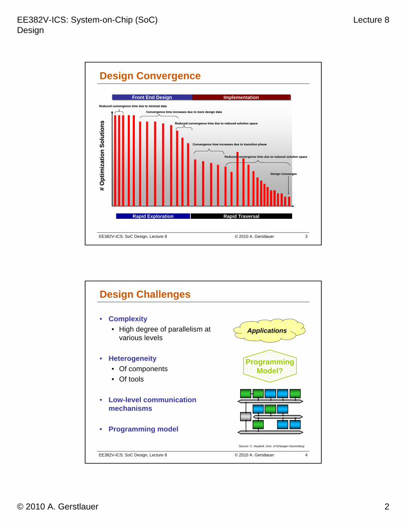
Design Convergence
Front End DesignFront End Design ImplementationImplementation
Rapid Exploration Rapid Traversal
# O
pti
miz
atio
n S
olu
tio
ns
# O
pti
miz
atio
n S
olu
tio
ns
Design ConvergesDesign Converges
Reduced convergence time due to minimal data Reduced convergence time due to minimal data
Convergence time increases due to more design data Convergence time increases due to more design data
Reduced convergence time due to reduced solution spaceReduced convergence time due to reduced solution space
Convergence time increases due to transition phase Convergence time increases due to transition phase
Reduced convergence time due to reduced solution spaceReduced convergence time due to reduced solution space
EE382V-ICS: SoC Design, Lecture 8 © 2010 A. Gerstlauer 4
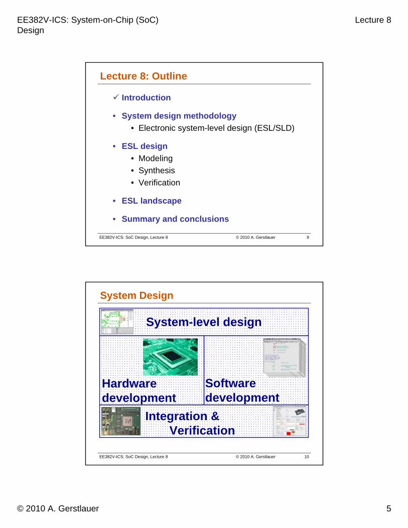
Design Challenges
Applications
ProgrammingModel?
• Complexity
• High degree of parallelism atvarious levels
• Heterogeneity
• Of components
• Of tools
• Low-level communicationmechanisms
• Programming model
Source: C. Haubelt, Univ. of Erlangen-Nuremberg

EE382V-ICS: System-on-Chip (SoC) Design
Lecture 8
© 2010 A. Gerstlauer 3
EE382V-ICS: SoC Design, Lecture 8 © 2010 A. Gerstlauer 5
Complexity Forces
Technology churn
Performance Throughput
Capacity
Availability
Security
Reliability
Functionality
Cost Compatibility
Robustness
“The challenge over the next 20 years will not be speed or cost or performance; it will be a question of complexity.”
Bill Raduchel, Chief Strategy Officer, Sun Microsystems
EE382V-ICS: SoC Design, Lecture 8 © 2010 A. Gerstlauer 6
Multi-Processor System-on-Chip (MPSoC)
Controller Bus
SystemMemory
Local Bus
Local RAM
Bridge
SharedRAM
DSP Bus
DSP RAM
MemoryController ASIP
DSP
HardwareAccelerator
Micro-Controller
HardwareAccelerator
VideoFront End
Source: C. Haubelt, Univ. of Erlangen-Nuremberg

EE382V-ICS: System-on-Chip (SoC) Design
Lecture 8
© 2010 A. Gerstlauer 4
EE382V-ICS: SoC Design, Lecture 8 © 2010 A. Gerstlauer 7
MPSoC Terminology
• Multi-processor
• Heterogeneous, asymmetric multi-processing (AMP)
• Distributed memory and operating system
• Multi-core
• Homogeneous, symmetric multi-processing (SMP)
• Shared memory and operating system
Multi-core processors in a multi-processor system
• Many-core
• > 10 cores per processor…
EE382V-ICS: SoC Design, Lecture 8 © 2010 A. Gerstlauer 8
Source: T. Noll, RWTH Aachen, via R. Leupers, “From ASIP to MPSoC”, Computer Engineering Colloquium, TU Delft, 2006
Processor Implementation Options
EE382V-ICS: System-on-Chip (SoC) Design
Lecture 8
© 2010 A. Gerstlauer 5
EE382V-ICS: SoC Design, Lecture 8 © 2010 A. Gerstlauer 9
Lecture 8: Outline
Introduction
• System design methodology
• Electronic system-level design (ESL/SLD)
• ESL design
• Modeling
• Synthesis
• Verification
• ESL landscape
• Summary and conclusions
EE382V-ICS: SoC Design, Lecture 8 © 2010 A. Gerstlauer 10
System Design
System-level design
Hardwaredevelopment
Softwaredevelopment
Integration & Verification

EE382V-ICS: System-on-Chip (SoC) Design
Lecture 8
© 2010 A. Gerstlauer 6
EE382V-ICS: SoC Design, Lecture 8 © 2010 A. Gerstlauer 11
system design
hardwaredevelopment
softwaredevelopment
integration & verification
Classical System Design Flow
(semi)automaticmanual
System requirement specification
System architecture design
Modeling
Hardware design
Software development
System
Integration & Verification
EE382V-ICS: SoC Design, Lecture 8 © 2010 A. Gerstlauer 12
Hardware-Centric Design Cycle
Time
Task
Specification Fixes in specification
HW design Fixes in hardware
HW verification
SW design Fixes in software
SW verification
Integration & verification

EE382V-ICS: System-on-Chip (SoC) Design
Lecture 8
© 2010 A. Gerstlauer 7
EE382V-ICS: SoC Design, Lecture 8 © 2010 A. Gerstlauer 13
Hardware-Centric Design Cycle
Time
Task
Specification Fixes in specification
HW design Fixes in hardware
HW verification
SW design Fixes in software
SW verification
Integration & verification✘
known if project is successful
✘
but you want to know here
✘
… and here
✘
… and here
EE382V-ICS: SoC Design, Lecture 8 © 2010 A. Gerstlauer 14
system design
hardwaredevelopment
softwaredevelopment
integration & verification
Electronic System-Level (ESL) Design Flow
(semi)automaticmanual
System requirement specification
High-level model
Hardware design Software development
System implementation
Integration & Verification
System-level design

EE382V-ICS: System-on-Chip (SoC) Design
Lecture 8
© 2010 A. Gerstlauer 8
EE382V-ICS: SoC Design, Lecture 8 © 2010 A. Gerstlauer 15
New ESL Design Cycle
Time
Task
Specification(high-level & arch. models) Fixes in specification
HW design Fixes in hardware
HW verification
SW design Fixes in software
SW verification
Integration & verification
Find good design options here
EE382V-ICS: SoC Design, Lecture 8 © 2010 A. Gerstlauer 16
system
component
logic
task
instructionarchitecture
RTL
gate
Hardware
Arch
ISA
Software
Implementation
Specification
Double Roof Model
Source: A. Gerstlauer, C. Haubelt, A. Pimentel, et al., “Electronic System-Level Synthesis Methodologies,“ TCAD, 2009.

EE382V-ICS: System-on-Chip (SoC) Design
Lecture 8
© 2010 A. Gerstlauer 9
EE382V-ICS: SoC Design, Lecture 8 © 2010 A. Gerstlauer 17
Design Methodologies
• Top down design• Starts with functional system
specification– Application behavior– Models of Computation (MoC)
• Successive refinement• Connect the hardware and
software design teams earlier in the design cycle.
• Allows hardware and software to be developed concurrently
• Goes through architectural mapping
• The hardware and software parts are either manually coded or obtained by refinement from higher model
• Ends with HW-SW co-verification and System Integration
• Platform based design • Starts with architecting a
processing platform for a given vertical application space
– Semiconductor, ASSP vendors
• Enables rapid creation and verification of sophisticated SoC designs variants
• PBD uses predictable and pre-verified firm and hard blocks
• PBD reduces overall time-to-market
– Shorten verification time
• Provides higher productivity through design reuse
• PBD allows derivative designs with added functionality
• Allows the user to focus on the part that differentiate his design
Source: Coware, Inc., 2005
Set of models and design steps (transformations)
EE382V-ICS: SoC Design, Lecture 8 © 2010 A. Gerstlauer 18
Top-Down ESL Design Environment
SLDesign
FunctionDesign
SystemDef.
HWDESIGN
SWDESIGN
HWFAB
SWCODING
INTEG.& TEST
PROTOTYPING ENVIRONMENTPrimarilyVirtual
PrimarilyPhysical
HW & SW CODESIGN
Cost Models
Copyright © 1995-1999 SCRA Used with Permission

EE382V-ICS: System-on-Chip (SoC) Design
Lecture 8
© 2010 A. Gerstlauer 10
EE382V-ICS: SoC Design, Lecture 8 © 2010 A. Gerstlauer 19
Flow To Implementation
Platform-Based Design (PBD)
SystemBehavior
SystemPlatform
Mapping
Refinement
BehaviorVerification
Architecture
Models of Computation
Performance models: Emb. SW, Comm.
and Comp. resources
HW/SW Partitioning,Scheduling & Estimation
Synthesis& Coding
Performance Analysis
and Simulation
Source: UC Berkeley, EECS249
Model Checking
EE382V-ICS: SoC Design, Lecture 8 © 2010 A. Gerstlauer 20
System Design Languages
• Netlists• Structure only: components and connectivity Gate-level [EDIF], system-level [SPIRIT/XML]
• Hardware description languages (HDLs)• Event-driven behavior: signals/wires, clocks• Register-transfer level (RTL): boolean logic Discrete event [VHDL, Verilog]
• System-level design languages (SLDLs)• Software behavior: sequential functionality/programs C-based [SpecC, SystemC, SystemVerilog]
EE382V-ICS: System-on-Chip (SoC) Design
Lecture 8
© 2010 A. Gerstlauer 11
EE382V-ICS: SoC Design, Lecture 8 © 2010 A. Gerstlauer 21
Lecture 8: Outline
Introduction
System design flow
• ESL design
• Modeling
• Synthesis
• Verification
• ESL landscape
• Summary and conclusions
EE382V-ICS: SoC Design, Lecture 8 © 2010 A. Gerstlauer 22
System Modeling
• Design models as abstraction of a design instance• Representation for validation and analysis• Specification for further implementation Documentation & specification
Systematic modeling flow and methodology• Set of models• Set of design steps From specification to implementation
Well-defined, rigorous system-level semantics• Unambiguous, explicit abstractions, models
– Objects and composition rules
Synthesis and verification

EE382V-ICS: System-on-Chip (SoC) Design
Lecture 8
© 2010 A. Gerstlauer 12
EE382V-ICS: SoC Design, Lecture 8 © 2010 A. Gerstlauer 23
Modeling Guidelines
• A model should capture exactly the aspects required by the system, and no more.
• There is not one model/algorithm/tool that fits all.
• Being formal is a prerequisite for algorithmic analysis.
• Formality means having a mathematical definition (semantics) for the properties of interest.
• Being compositional is a prerequisite for scalability.
• Compositionality is the ability of breaking a task about A||B into two subtasks about A and B, respectively.
Source: UC Berkeley, EECS249
EE382V-ICS: SoC Design, Lecture 8 © 2010 A. Gerstlauer 24
Separation of Concerns
Managing Complexity
OrthogonalizingOrthogonalizingconcernsconcernsacrossacross
multiple levelsmultiple levelsof of
abstractionabstraction
Behavior Vs.
Architecture
Computation Vs.
Communication
Source: UC Berkeley, EECS249

EE382V-ICS: System-on-Chip (SoC) Design
Lecture 8
© 2010 A. Gerstlauer 13
EE382V-ICS: SoC Design, Lecture 8 © 2010 A. Gerstlauer 25
System Design Flow
Computation
Co
mm
un
icat
ion
A B
C
D F
Un-timed
Approximate-timed
Cycle-timed
Un-timed
Approximate-timed
A. System specification modelB. Timed functional modelC. Transaction-level model (TLM)D. Bus cycle-accurate model (BCAM)E. Computation cycle-accurate model (CCAM)F. Cycle-accurate model (CAM)
E
Cycle-timed
• Abstraction based on level of detail & granularity
• Computation and communication
System design flow
Path from model A to model F
Source: L. Cai, D. Gajski. “Transaction level modeling: An overview”, ISSS 2003
EE382V-ICS: SoC Design, Lecture 8 © 2010 A. Gerstlauer 26
Computation vs. Communication
ComputationComputationCommunicationCommunication
Bus Model Device Model
Behavior can be described algorithmically, without the burden of the handshaking and control logic associated with bus communication.
Communication can be described in a wide range of fashions, from high-level messages, to detailed signal level handshakes without impacting the behavior description.
c = a * b;get a;get b;send c;
Must be synchronized
• Separation of concerns
• Flexibility in modeling
• IP reuse
Source: Coware, Inc., 2005
EE382V-ICS: System-on-Chip (SoC) Design
Lecture 8
© 2010 A. Gerstlauer 14
EE382V-ICS: SoC Design, Lecture 8 © 2010 A. Gerstlauer 27
Computation Models
• Application model• Model of Computation (MoC)
– Process-/state-based [KPN, SDF, FSM, …]
• Back-annotated execution timing– Timing granularity (basic block level)
• Processor model• Operating system
– Real-time multi-tasking (RTOS), drivers
• Hardware abstraction layer (HAL)– Media accesses
• Processor hardware– Bus I/O & interrupts
• Instruction-set model• Instruction-set or micro-architecture
– Down to cycle-accurate behavior
B1 B2
OS
CP
U
Drv
Interrupts
Bus
ISRHAL
Process B1(){
…waitfor(15000);…waitfor(25000);…
};
EE382V-ICS: SoC Design, Lecture 8 © 2010 A. Gerstlauer 28
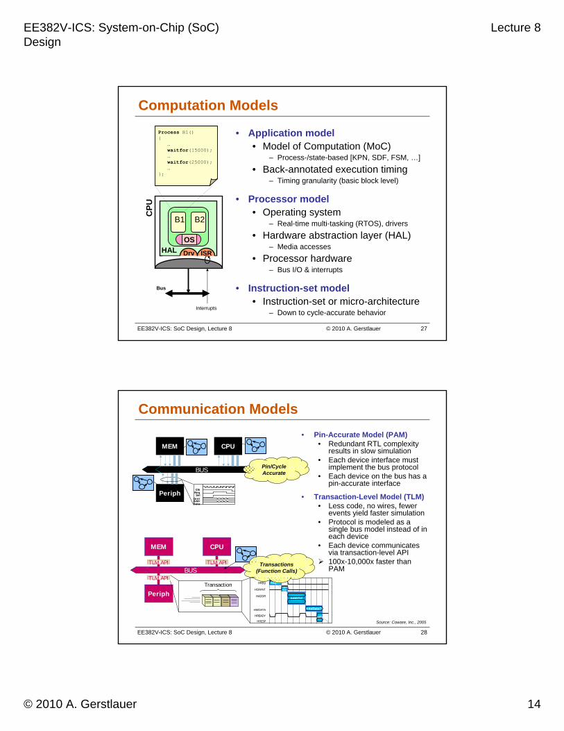
Communication Models
• Pin-Accurate Model (PAM)• Redundant RTL complexity
results in slow simulation• Each device interface must
implement the bus protocol• Each device on the bus has a
pin-accurate interface
• Transaction-Level Model (TLM)• Less code, no wires, fewer
events yield faster simulation• Protocol is modeled as a
single bus model instead of in each device
• Each device communicates via transaction-level API
100x-10,000x faster than PAMBUS
MEM CPU
Periph
TLM API TLM API
TLM APIHREQ
HADDR
HGRANT
HWDATA
HRESP
HREADY
ReqTrfGrant
Trf
AddrTrf
WriteDataTrf
EotTrf
Transaction
BUS
MEM CPU
Periph Req
GrntSel
DataAddr
Clk
Source: Coware, Inc., 2005
Pin/Cycle Accurate
Transactions (Function Calls)
EE382V-ICS: System-on-Chip (SoC) Design
Lecture 8
© 2010 A. Gerstlauer 15
EE382V-ICS: SoC Design, Lecture 8 © 2010 A. Gerstlauer 29
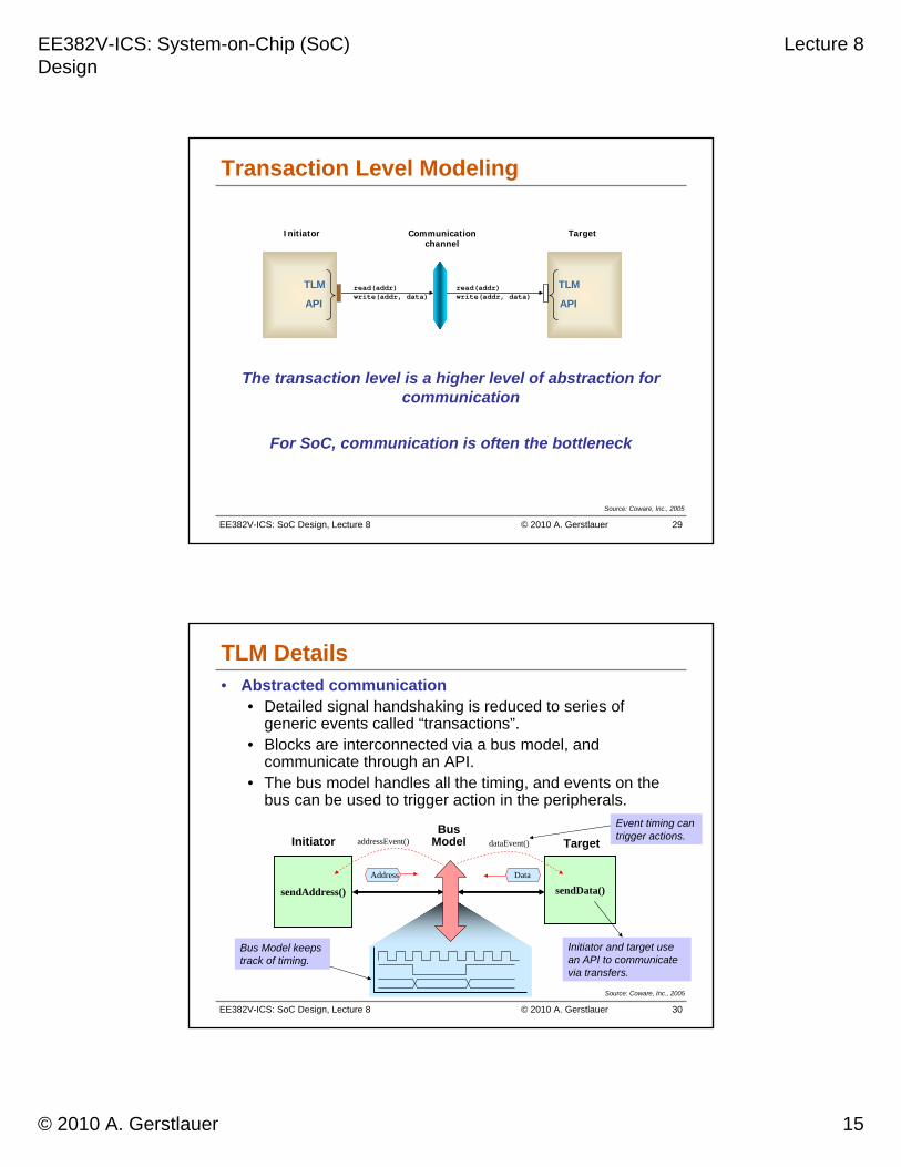
Transaction Level Modeling
The transaction level is a higher level of abstraction for communication
For SoC, communication is often the bottleneck
Communication channel
TargetInitiator
TLM
API
TLM
API
read(addr)write(addr, data)
read(addr)write(addr, data)
Source: Coware, Inc., 2005
EE382V-ICS: SoC Design, Lecture 8 © 2010 A. Gerstlauer 30
TLM Details• Abstracted communication
• Detailed signal handshaking is reduced to series of generic events called “transactions”.
• Blocks are interconnected via a bus model, and communicate through an API.
• The bus model handles all the timing, and events on the bus can be used to trigger action in the peripherals.
sendAddress()
InitiatorBus
Model
Bus Model keeps track of timing.
Address Data
Initiator and target use an API to communicate via transfers.
Target
sendData()
Event timing can trigger actions. addressEvent() dataEvent()
Source: Coware, Inc., 2005

EE382V-ICS: System-on-Chip (SoC) Design
Lecture 8
© 2010 A. Gerstlauer 16
EE382V-ICS: SoC Design, Lecture 8 © 2010 A. Gerstlauer 31
SystemC/TLM 2.0
• Pointer to transaction object is passed from module to module using forward and backward paths
• Transactions are of generic payload type
InterconnectInitiator/Target
TargetInitiatorForward path
Backward path
Forward path
Backward path
Command
Address
Data
Byte enables
Response status
Extensions
Source: OSCI TLM-2.0
EE382V-ICS: SoC Design, Lecture 8 © 2010 A. Gerstlauer 32
SystemC/TLM 2.0 Coding Styles
• Loosely-timed
• Sufficient timing detail to boot OS and simulate multi-core systems
• Each transaction has 2 timing points: begin (call) and end (return)
• Approximately-timed
• Cycle-approximate or cycle-count-accurate
• Sufficient for architectural exploration
• Each transaction has at least4 timing points
END_REQ
BEGIN_RESP
END_RESP
BEGIN_REQ
Initiator Target
BEGIN
END
Initiator Target
Source: OSCI TLM-2.0

EE382V-ICS: System-on-Chip (SoC) Design
Lecture 8
© 2010 A. Gerstlauer 17
EE382V-ICS: SoC Design, Lecture 8 © 2010 A. Gerstlauer 33
Blocking and Non-Blocking Transports
• Blocking transport interface
• Typically used with loosely-timed coding style
• tlm_blocking_transport_ifvoid b_transport(TRANS&, sc_time&);
• Non-blocking transport interface
• Typically used with approximately-timed coding style
• Includes transaction phases
• tlm_fw_nonblocking_transport_iftlm_sync_enum nb_transport_fw(TRANS&, PHASE&, sc_time&);
• tlm_bw_nonblocking_transport_iftlm_sync_enum nb_transport_bw(TRANS&, PHASE&, sc_time&);
Source: OSCI TLM-2.0
EE382V-ICS: SoC Design, Lecture 8 © 2010 A. Gerstlauer 34
Blocking Transport
TargetInitiator
wait(30ns);
Simulation time 0ns
b_transport(t, 0ns);
b_transport(t, 0ns);call
return
Simulation time 30ns
b_transport(t, 0ns);
b_transport(t, 0ns);call
return
Simulation time 0ns
Source: OSCI TLM-2.0

EE382V-ICS: System-on-Chip (SoC) Design
Lecture 8
© 2010 A. Gerstlauer 18
EE382V-ICS: SoC Design, Lecture 8 © 2010 A. Gerstlauer 35
Non-Blocking Transport
TargetInitiator
nb_transport(TLM_ACCEPTED, -, -);
nb_transport(-, END_REQ, 0ns);
nb_transport(TLM_ACCEPTED, -, -);
nb_transport(-, BEGIN_REQ, 0ns);
nb_transport(TLM_ACCEPTED, -, -);
nb_transport(-, END_RESP, 0ns);
nb_transport(TLM_ACCEPTED, -, -);
nb_transport(-, BEGIN_RESP, 0ns);
Source: OSCI TLM-2.0
EE382V-ICS: SoC Design, Lecture 8 © 2010 A. Gerstlauer 36
Virtual Platform Prototyping
Computation refinement
Communication refinement
Untimed TLM (LT/AT) PCAM
Virtual Prototype

EE382V-ICS: System-on-Chip (SoC) Design
Lecture 8
© 2010 A. Gerstlauer 19
EE382V-ICS: SoC Design, Lecture 8 © 2010 A. Gerstlauer 37
Not ModeledNot Modeled--Point to pointPoint to point
--MemoryMemory--mappedmapped
Abstraction Levels
Functional ValidationFunctional Validation
System Partitioning and Assembly
-Exploration and analysis
System Partitioning and System Partitioning and AssemblyAssembly
--Exploration and analysisExploration and analysis
Emb. System Modeling-Executable spec. capture
-Functional testing
Emb. System ModelingEmb. System Modeling--Executable spec. captureExecutable spec. capture
--Functional testingFunctional testing
RTL Design & Verification-Block design and unit test-Validation in the system
RTL Design & VerificationRTL Design & Verification--Block design and unit testBlock design and unit test--Validation in the systemValidation in the system
System-level Verification-Complete design at RTL-System-level testbench
SystemSystem--level Verificationlevel Verification--Complete design at RTLComplete design at RTL--SystemSystem--level testbenchlevel testbench
Architectural ValidationArchitectural Validation
Hardware RefinementHardware Refinement
RTL VerificationRTL Verification
RTLRTL RTLRTL
TimedTimedBusBus--FunctionalFunctional
UntimedUntimed
ApproximatelyApproximatelyTimed TLMTimed TLM
CycleCycle--AccurateAccurateTLMTLM
(Transfer Level)(Transfer Level)
RTLRTL
InstructionInstructionAccurateAccurate
CycleCycleAccurateAccurate
Processor Interconnect Peripheral
HostHost--compiledcompiled
Loosely TimedLoosely TimedTLMTLM
RTLRTL(DUT)(DUT)
TFTF(rest)(rest)
Incr
easi
ng S
cope
for
Rel
ativ
e O
ptim
izat
ion
Incr
easi
ng S
cope
for
Rel
ativ
e O
ptim
izat
ion
Incr
easi
ng S
imul
atio
n Pe
rfor
man
ceIn
crea
sing
Sim
ulat
ion
Perf
orm
ance
Source: Coware, Inc., 2005
EE382V-ICS: SoC Design, Lecture 8 © 2010 A. Gerstlauer 38
UT
IA ISSTLM Bus
Log A C C U R A C Y
Log
S P
E E
D
SystemCExecutable TLM
100Kcps
1MIPS
10MIPS
10Kcps
100cps
1Kcps
CycleAccurate
-TLM
Pin-accuratew/RTL
RTL
Host-based
Re-use for Early
SoftwareDevelopment
Re-use for System-level
HardwareVerification
ESLArchitectural
Design LT3 Mcps
CA150 kps
PAM+RTL15 kps
Speed vs. Accuracy

EE382V-ICS: System-on-Chip (SoC) Design
Lecture 8
© 2010 A. Gerstlauer 20
EE382V-ICS: SoC Design, Lecture 8 © 2010 A. Gerstlauer 39
Lecture 8: Outline
Introduction
System design methodology
• ESL design
Modeling
• Synthesis
• Verification
• ESL landscape
• Summary and conclusions
EE382V-ICS: SoC Design, Lecture 8 © 2010 A. Gerstlauer 40
Design Automation
• Synthesis = Decision making + model refinement
Successive, stepwise model refinement Layers of implementation detail
RefinementRefinement
Model nModel n
DBDB
Model n+1Model n+1
Specification modelSpecification model
Implementation modelImplementation model
Optim. algorithmOptim. algorithm
GUIGUI
Design decisions

EE382V-ICS: System-on-Chip (SoC) Design
Lecture 8
© 2010 A. Gerstlauer 21
EE382V-ICS: SoC Design, Lecture 8 © 2010 A. Gerstlauer 41
X-Chart
Behavior Constraints
Structure Qualitynumbers
Synthesis
Decisionmaking Refinement
Application Platform
Source: A. Gerstlauer, C. Haubelt, A. Pimentel, et al., “Electronic System-Level Synthesis Methodologies,“ TCAD, 2009.
Transaction Level Model
Latency, Area, Throuput, etc
EE382V-ICS: SoC Design, Lecture 8 © 2010 A. Gerstlauer 42
Platform-Based System Synthesis
Application
Optimal Mapping ?
Platform

EE382V-ICS: System-on-Chip (SoC) Design
Lecture 8
© 2010 A. Gerstlauer 22
EE382V-ICS: SoC Design, Lecture 8 © 2010 A. Gerstlauer 43
Resource Allocation
• Resource allocation, i.e., select resources from a platform for implementing the application
EE382V-ICS: SoC Design, Lecture 8 © 2010 A. Gerstlauer 44
Process Binding
• Process mapping, i.e., bind processes onto allocated computational resources

EE382V-ICS: System-on-Chip (SoC) Design
Lecture 8
© 2010 A. Gerstlauer 23
EE382V-ICS: SoC Design, Lecture 8 © 2010 A. Gerstlauer 45
Channel Routing
• Channel mapping, i.e., assign channels to paths over busses and address spaces
EE382V-ICS: SoC Design, Lecture 8 © 2010 A. Gerstlauer 46
Design Space Exploration
• Design Space Exploration is an iterative process:
• How can a single design point be evaluated?
• How can the design space be covered during the exploration process?
Covering the design space
Evaluating design points

EE382V-ICS: System-on-Chip (SoC) Design
Lecture 8
© 2010 A. Gerstlauer 24
EE382V-ICS: SoC Design, Lecture 8 © 2010 A. Gerstlauer 47
Optimization Approaches
• Exact methods• Enumeration, (Integer) Linear Programs
• Heuristics• Constructive
– Random mapping, hierarchical clustering
• Iterative– Random search, simulated annealing, min-cut (Kernighan-Lin)
• Set-based (“intelligent” randomized search)– Evolutionary Algorithms (EA),
Particle Swarm Optimization (PSO), Ant Colony Optimization (ACO)
Exact, constructive & iterative methods are prohibitive Large design space, multiple objectives, dynamic behavior
Set-based approaches Randomized, problem independent (black box), Pareto set
EE382V-ICS: SoC Design, Lecture 8 © 2010 A. Gerstlauer 48
Evaluation Approaches
• Dynamic simulation• Profiling, ISS/RTL co-simulation Long simulation times, corner cases
• Static analysis• Component-level estimation
[Worst-Case Execution Time (WCET)]• System-level cost functions, real-time calculus
[Modular Performance Analysis (MPA)] Inaccurate bounds, manual interference (false paths)
Combinations• Host-compiled simulation• Trace-driven simulation Tradeoff between accuracy and speed
EE382V-ICS: System-on-Chip (SoC) Design
Lecture 8
© 2010 A. Gerstlauer 25
EE382V-ICS: SoC Design, Lecture 8 © 2010 A. Gerstlauer 49
Lecture 8: Outline
Introduction
System design methodology
• ESL design
Modeling
Synthesis
• Verification
• ESL landscape
• Summary and conclusions
EE382V-ICS: SoC Design, Lecture 8 © 2010 A. Gerstlauer 50
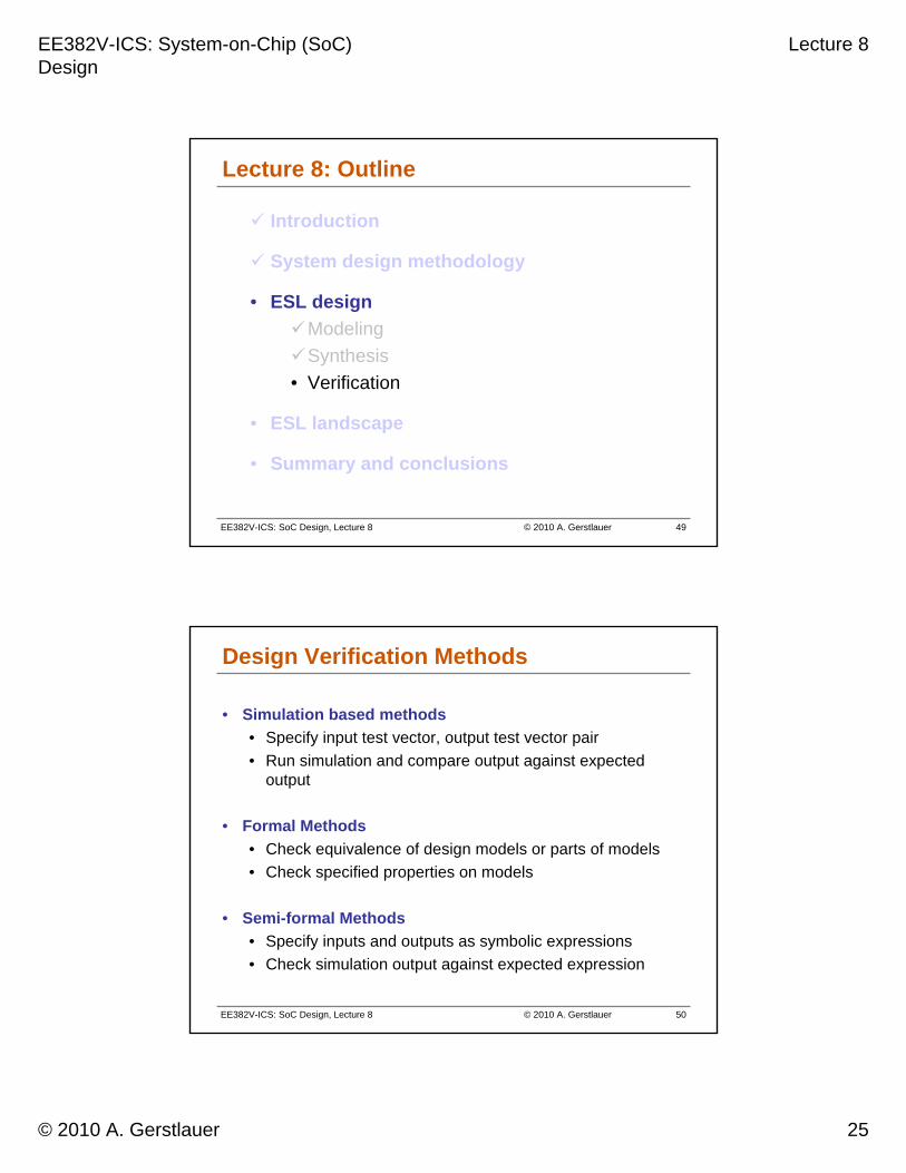
Design Verification Methods
• Simulation based methods
• Specify input test vector, output test vector pair
• Run simulation and compare output against expected output
• Formal Methods
• Check equivalence of design models or parts of models
• Check specified properties on models
• Semi-formal Methods
• Specify inputs and outputs as symbolic expressions
• Check simulation output against expected expression

EE382V-ICS: System-on-Chip (SoC) Design
Lecture 8
© 2010 A. Gerstlauer 26
EE382V-ICS: SoC Design, Lecture 8 © 2010 A. Gerstlauer 51
Simulation
• Create test vectors and simulate model• Simulation, debugging and visualization tools
[Synopsys VCS, Mentor ModelSim, Cadence NC-Sim]
• Inputs• Specification
– Used to create interesting stimuli and monitors
• Model of DUT– Typically written in HDL or C or both
• Output• Failed test vectors
– Pointed out in different design representations by debugging tools
DUT
Stim
ulus
Mon
itors
Specification
EE382V-ICS: SoC Design, Lecture 8 © 2010 A. Gerstlauer 52
Equivalence Checking
• LEC uses boolean algebra to check for logic equivalence
1 = 1’ ?2 = 2’ ?
inpu
ts
outp
uts
12
inpu
ts
outp
uts1’
2’
Equivalence result
p
q
x
y
a
b
r
s
x
ya
bty
b
pr
qr
ps pt
qs qt
xx
yx
xyxy
yy
yy
aa
bb
bb
× =
• SEC uses FSMs to check for sequential equivalence

EE382V-ICS: System-on-Chip (SoC) Design
Lecture 8
© 2010 A. Gerstlauer 27
EE382V-ICS: SoC Design, Lecture 8 © 2010 A. Gerstlauer 53
Model Checking
• Model M satisfies property P? [Clarke, Emerson ’81]
• Inputs
• State transition system representation of M
• Temporal property P as formula of state properties
• Output
• True (property holds)
• False + counter-example (property does not hold)
True /False + counter-example
ModelChecker
P = P2 always leads to P4s1
s4 s3
s2P1
P3P4
P2
M
EE382V-ICS: SoC Design, Lecture 8 © 2010 A. Gerstlauer 54
Lecture 8: Outline
Introduction
System design methodology
ESL design
• ESL landscape
• Commercial tools
• Academic tools
• Summary and conclusions

EE382V-ICS: System-on-Chip (SoC) Design
Lecture 8
© 2010 A. Gerstlauer 28
EE382V-ICS: SoC Design, Lecture 8 © 2010 A. Gerstlauer 55
Bri
dg
e
CPU Mem
HW IP
Arb
iter
v1
C1
B1 B2
B3 B4
C2
CommunicationComputation &
System SynthesisFront-End
System SynthesisFront-End
Software / HardwareSynthesisBack-End
Software / HardwareSynthesisBack-End
TLM
Inst
ruct
ion
-Set
Sim
ula
tor
(IS
S) C
-based
RT
L
Software Object Code
Hardware VHDL/Verilog
Application specification
Transaction-Level ModelsTLMTLMTLMn
Platform library
Electronic System-Level (ESL) Landscape
SystemC, CoWare, …
Mentor Catapult,Forte, …
VaST, OVPVirtutech,…
Green Hills,gcc, VxWorks, …
Synopsys Design Compiler, …
SPIRIT/IP-XACT (XML)
MARTE (UML)
Tensilica
Matlab/Simulink,LabView, …
System-Level Design Languages (SLDLs)
C/C++ code
Academic Tools
EE382V-ICS: SoC Design, Lecture 8 © 2010 A. Gerstlauer 56
ESL Tools
• Electronic System-Level (ESL) terminology• Often single hardware unit only
– C-to-RTL high-level synthesis (HLS) [Mentor Catapult, Forte Cynthesizer]
• System-level across hardware and software boundaries• System-level frontend• Hardware and software synthesis backend
Commercial tools for modeling and simulation• Algorithmic modeling (MoC) [UML, Matlab/Simulink, Labview]• Virtual system prototyping (TLM) [Coware, VaST, Virtutech]Only horizontal integration across models / components
Academic tools for synthesis and verification• MPSoC synthesis [SCE, Metropolis, SCD, PeaCE, Deadalus]Vertical integration for path to implementation

EE382V-ICS: System-on-Chip (SoC) Design
Lecture 8
© 2010 A. Gerstlauer 29
EE382V-ICS: SoC Design, Lecture 8 © 2010 A. Gerstlauer 57
Academic MPSoC Design Tools
∘∙∙∘∙∙
Comp. refine
∙∙∙SystemCoDesigner
∙SCE
∘∘∘PeaCE/HoPES
∘Metropolis
∘∘∙∙Koski
∘∘∙∙Daedalus
Comm. refine
Comm. decision
Comp. decision
DSEApproach
Source: A. Gerstlauer, C. Haubelt, A. Pimentel, et al., “Electronic System-Level Synthesis Methodologies,“ TCAD, 2009.
EE382V-ICS: SoC Design, Lecture 8 © 2010 A. Gerstlauer 58
System Design Flow Summary
Design Export… after initial platform configuration through design refinement and
communication synthesis
Functional IP
C/C++SDLSPW
Simulink
Synthesis / Place & Route etc.
Implementation Level Verification
SoftwareAssembly
HardwareAssembly
CommunicationRefinement, Integration &
Synthesis
Performance Analysis and Platform Configuration
System Integration
Platform Function
Platform Architecture
Embedded System Requirements
Platform Configuration
… at theun-clocked, timing-
awaresystem level
Architecture IP
CPU/DSPRTOS
Bus, MemoryHWSW