ee152 green electronics - stanford...
TRANSCRIPT
EE152 Green Electronics
Bridge Converters & Soft Switching
10/24/13
Prof. William Dally Computer Systems Laboratory
Stanford University

Course Logistics • Lab 4 signed off this week • Lab 5 out this week • Homework 4 • Solar day next Thursday

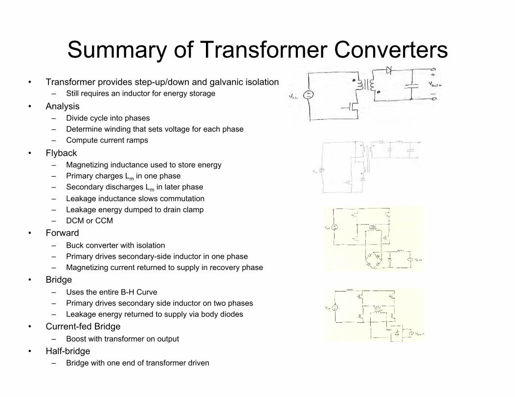
Summary of Transformer Converters • Transformer provides step-up/down and galvanic isolation
– Still requires an inductor for energy storage
• Analysis – Divide cycle into phases – Determine winding that sets voltage for each phase – Compute current ramps
• Flyback – Magnetizing inductance used to store energy – Primary charges Lm in one phase – Secondary discharges Lm in later phase – Leakage inductance slows commutation – Leakage energy dumped to drain clamp – DCM or CCM
• Forward – Buck converter with isolation – Primary drives secondary-side inductor in one phase – Magnetizing current returned to supply in recovery phase
• Bridge – Uses the entire B-H Curve – Primary drives secondary side inductor on two phases – Leakage energy returned to supply via body diodes
• Current-fed Bridge – Boost with transformer on output
• Half-bridge – Bridge with one end of transformer driven

Using the B-H Curve • Flyback and Forward converters only use half the B-H
curve • Also, each winding conducts only half the time • Thus, they require larger magnetic components per
unit power than would otherwise be required • Bridge converters use the whole B-H curve and can
conduct much of the cycle
Fundamentals of Power Electronics Chapter 13: Basic Magnetics Theory37
Core loss: Hysteresis loss
(energy lost per cycle) = (core volume) (area of B–H loop)
The term Aclm is the volume of
the core, while the integral is
the area of the B–H loop.
Hysteresis loss is directly proportional
to applied frequency
B
H
Area
HdBone cycle
W = Aclm HdBone cycle
PH = f Aclm HdBone cycle

Full-Bridge Converter
UL UR
LL LR
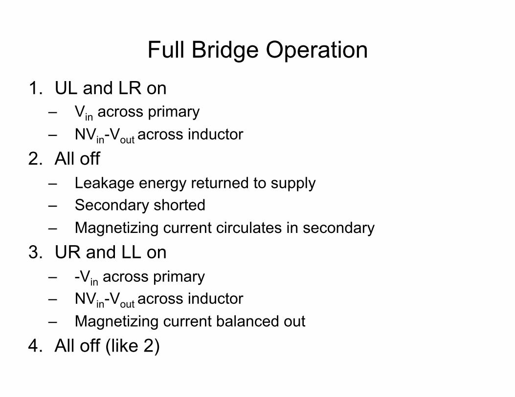
Full Bridge Operation 1. UL and LR on
– Vin across primary – NVin-Vout across inductor
2. All off – Leakage energy returned to supply – Secondary shorted – Magnetizing current circulates in secondary
3. UR and LL on – -Vin across primary – NVin-Vout across inductor – Magnetizing current balanced out
4. All off (like 2)
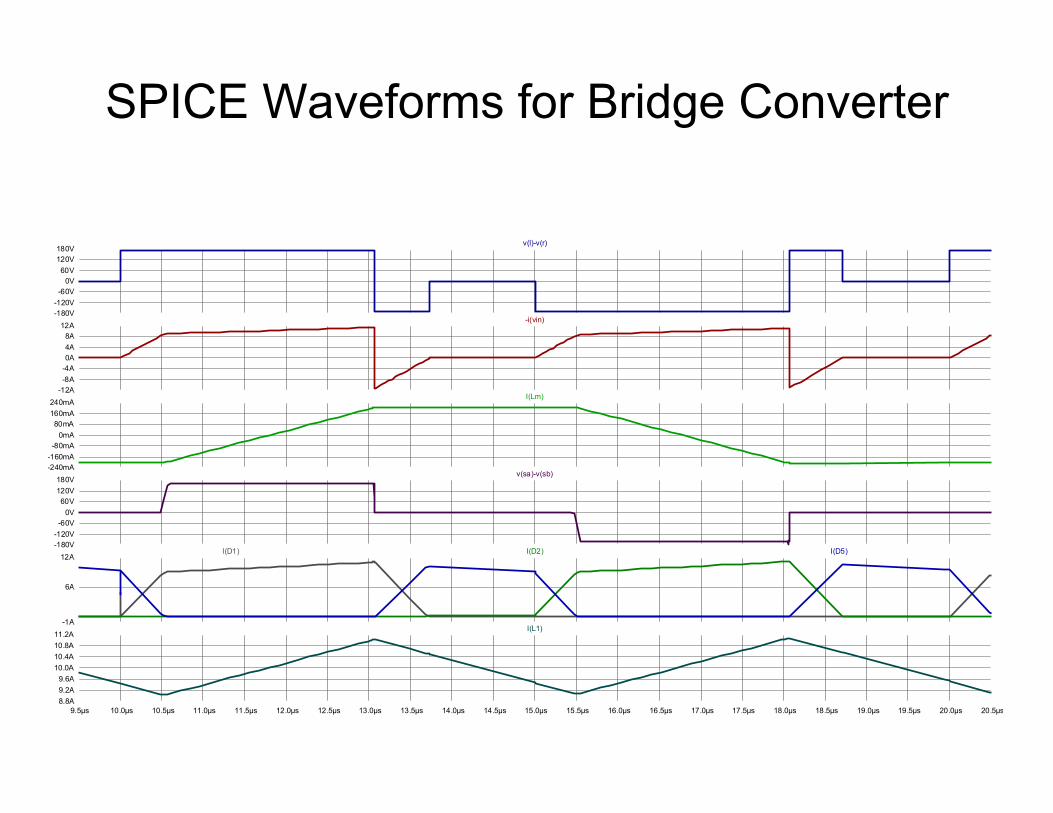
SPICE Waveforms for Bridge Converter
9.5µs 10.0µs 10.5µs 11.0µs 11.5µs 12.0µs 12.5µs 13.0µs 13.5µs 14.0µs 14.5µs 15.0µs 15.5µs 16.0µs 16.5µs 17.0µs 17.5µs 18.0µs 18.5µs 19.0µs 19.5µs 20.0µs 20.5µs8.8A9.2A9.6A10.0A10.4A10.8A11.2A-1A
6A
12A-180V-120V-60V0V60V120V180V
-240mA-160mA-80mA0mA80mA160mA240mA-12A-8A-4A0A4A8A12A
-180V-120V-60V0V60V120V180V
I(L1)
I(D1) I(D2) I(D5)
v(sa)-v(sb)
I(Lm)
-i(vin)
v(l)-v(r)
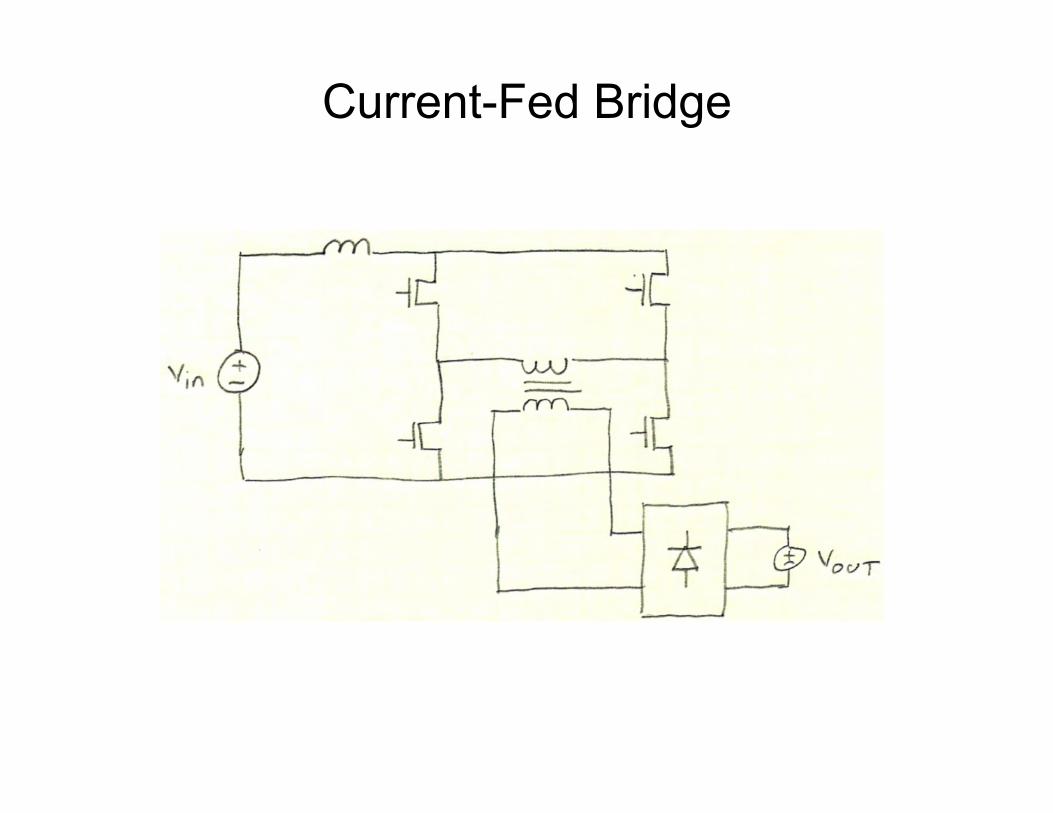
Current-Fed Bridge

Current-Fed Bridge Operation 1. All four switches on
– Vin across input inductor – current increases – Primary shorted – Output open
2. UR and LL on – Vin – NVout across input inductor – current decreases – Vout across secondary – Current delivered to output
3. All four switches on (like 1) 4. UL and LR on (like 2 but)
– -Vout across secondary

SPICE Waveforms for Current-Fed Bridge
11.5µs 12.0µs 12.5µs 13.0µs 13.5µs 14.0µs 14.5µs 15.0µs 15.5µs 16.0µs 16.5µs 17.0µs 17.5µs 18.0µs 18.5µs 19.0µs 19.5µs 20.0µs 20.5µs 21.0µs 21.5µs 22.0µs 22.5µs-1A
0A1A
2A
3A
4A5A
6A
7A
8A9A
10A
11A-240V-200V
-160V-120V
-80V-40V
0V40V
80V120V
160V200V
240V-250mA
-200mA
-150mA
-100mA
-50mA
0mA
50mA
100mA
150mA
200mA
250mA
300mA9.0A
9.3A
9.6A
9.9A
10.2A
10.5A
10.8A
11.1A
11.4A
11.7A
12.0A
-480V-400V
-320V-240V
-160V-80V0V
80V160V
240V320V
400V480V
I(D1) I(D2)
v(sa)-v(sb)
I(Lm)
I(L1)
v(l)-v(r)
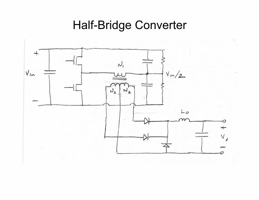
Half-Bridge Converter

Secondary Circuits
Full bridge Less copper Two diode drops Lower voltage diodes
Center-tapped secondary Twice the copper One diode drop Higher voltage diodes
Either can use synchronous rectification
Summary of Transformer Converters • Transformer provides step-up/down and galvanic isolation
– Still requires an inductor for energy storage
• Analysis – Divide cycle into phases – Determine winding that sets voltage for each phase – Compute current ramps
• Flyback – Magnetizing inductance used to store energy – Primary charges Lm in one phase – Secondary discharges Lm in later phase – Leakage inductance slows commutation – Leakage energy dumped to drain clamp – DCM or CCM
• Forward – Buck converter with isolation – Primary drives secondary-side inductor in one phase – Magnetizing current returned to supply in recovery phase
• Bridge – Uses the entire B-H Curve – Primary drives secondary side inductor on two phases – Leakage energy returned to supply via body diodes
• Current-fed Bridge – Boost with transformer on output
• Half-bridge – Bridge with one end of transformer driven

Soft Switching • Only switch a FET when:
– Zero voltage across it (ZVS) – Zero current through it (ZCS) – Both

Hard Switching • MOSFETs dissipate no power when they are off. • They dissipate very little power when they are on.
– I2Ron = (10A)2(.002Ω) = 0.2W
• They dissipate a lot of power during switching events • Simple model is
– Esw = tswIV = (50ns)(10A)(48V) = 24µJ – Psw = fEsw = (200kHz)(24µJ)=4.8W
• Actual Esw can be much higher due to shoot through.
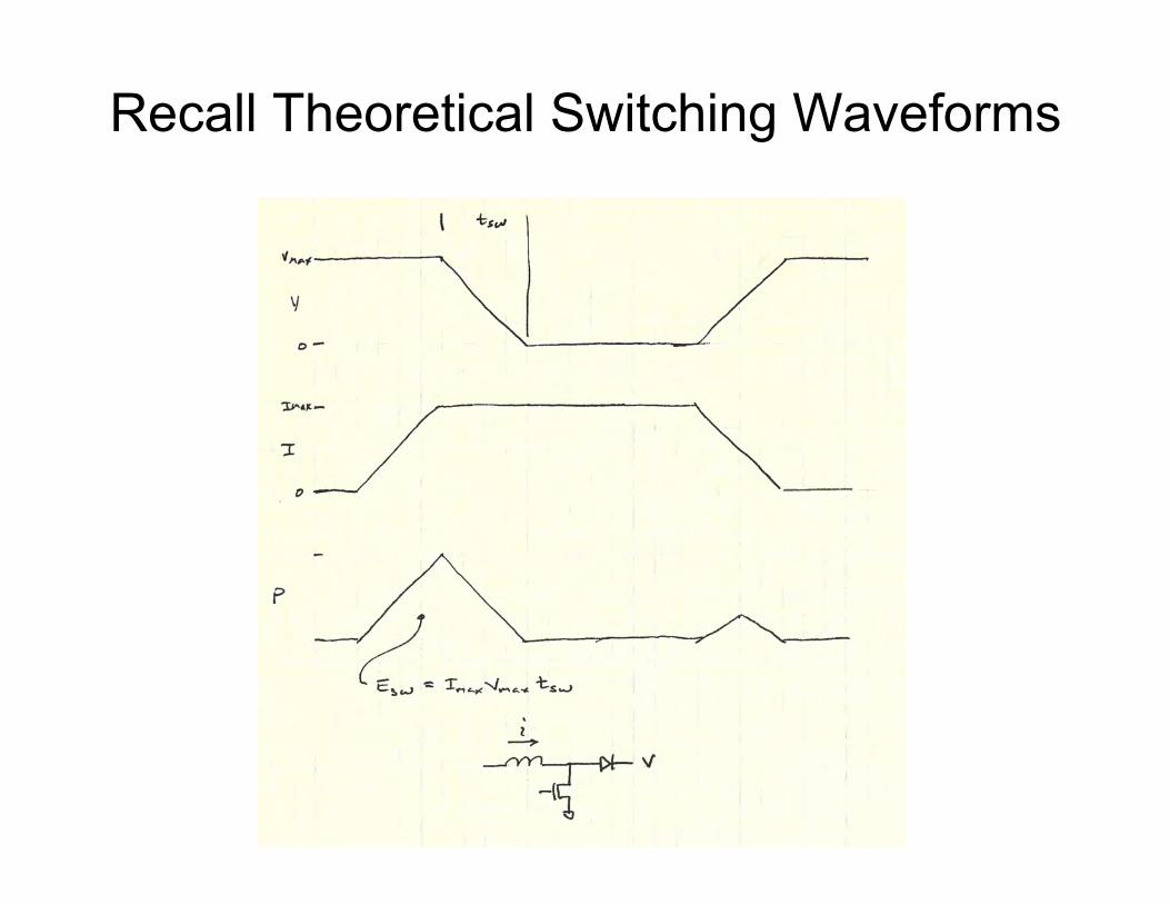
Recall Theoretical Switching Waveforms

Boost Converter

M1 On Transient – 36µJ
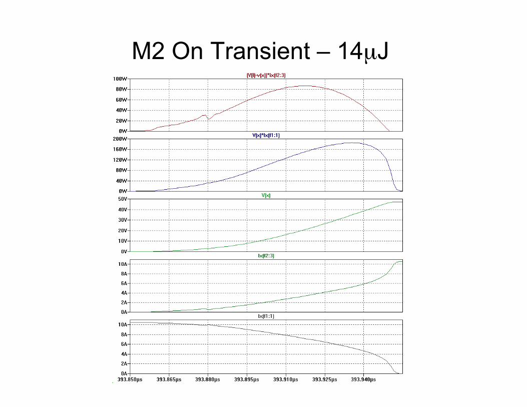
M2 On Transient – 14µJ
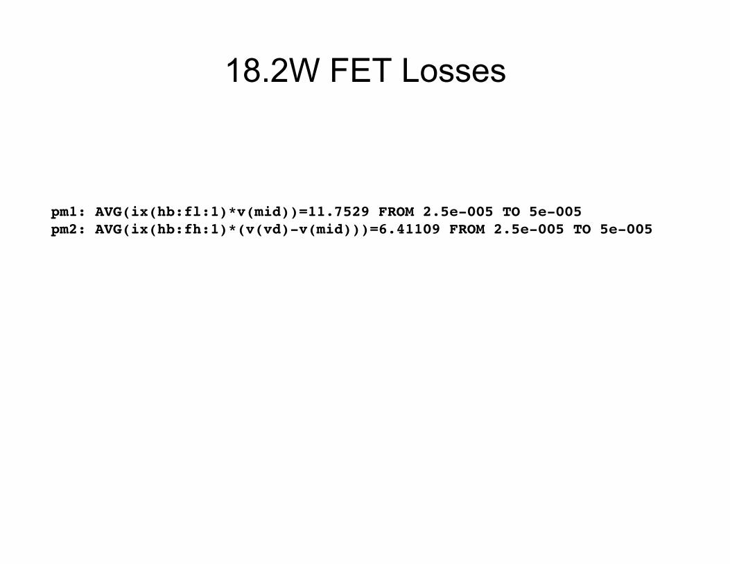
18.2W FET Losses
pm1: AVG(ix(hb:fl:1)*v(mid))=11.7529 FROM 2.5e-005 TO 5e-005!pm2: AVG(ix(hb:fh:1)*(v(vd)-v(mid)))=6.41109 FROM 2.5e-005 TO 5e-005!

How do we save this Switching Power?

Soft Switching • Zero-current switching (ZCS)
Turn on/off FET only when current through FET is zero through transition.
• Zero-voltage switching (ZVS) Turn on/off FET only when voltage across FET is zero through transition.

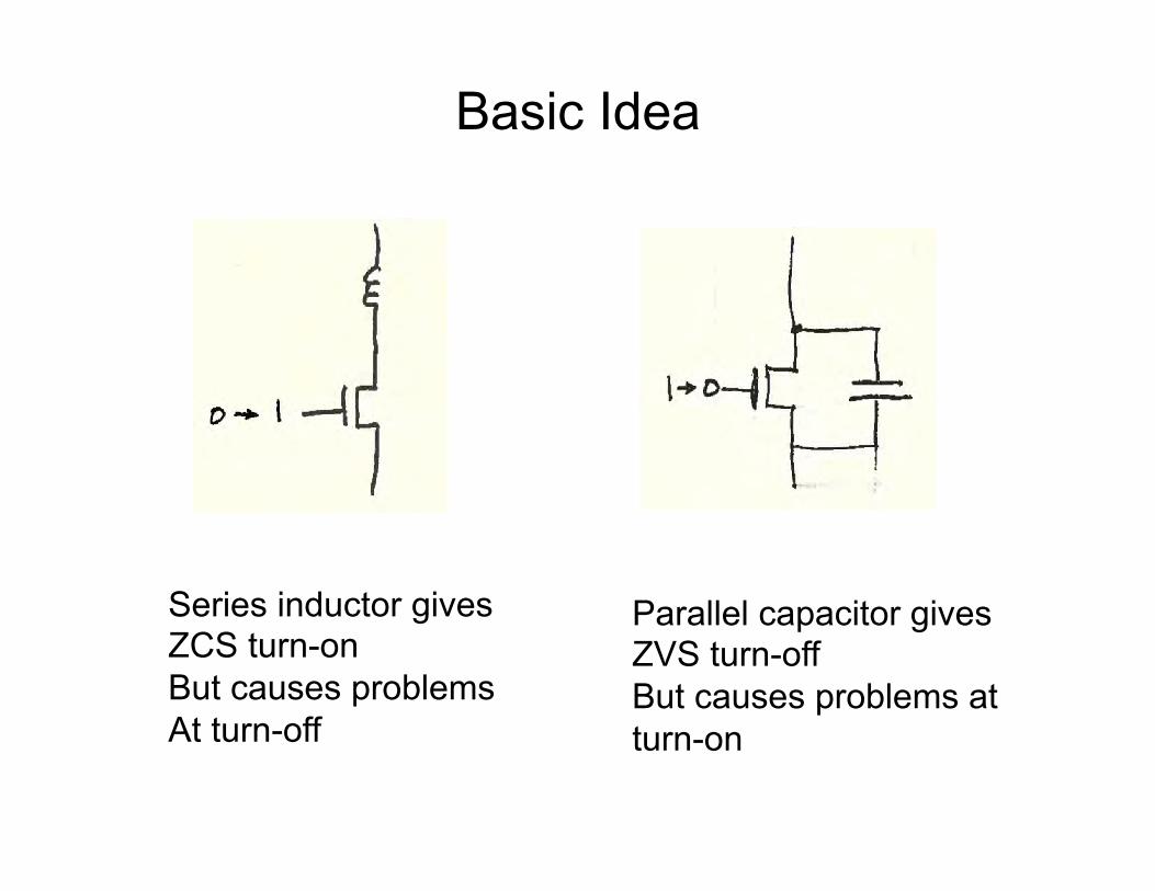
Basic Idea
Series inductor gives ZCS turn-on But causes problems At turn-off
Basic Idea
Series inductor gives ZCS turn-on But causes problems At turn-off
Parallel capacitor gives ZVS turn-off But causes problems at turn-on

Combination
Inductor gives ZCS turn-on Capacitor gives ZVS turn-off Capacitor absorbs inductor current on turn-off Diode isolates capacitor on turn-on Magic circuit recycles energy on capacitor

Example 1 – Buck with Synchronous Rectifier
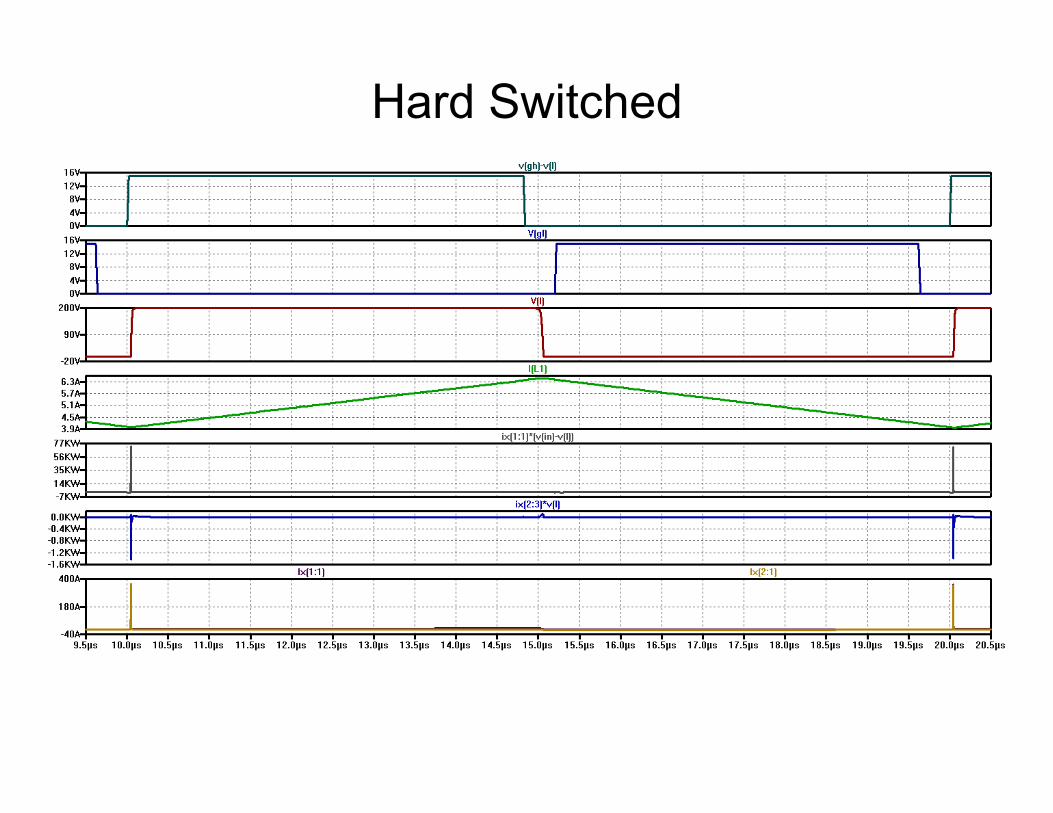
Hard Switched
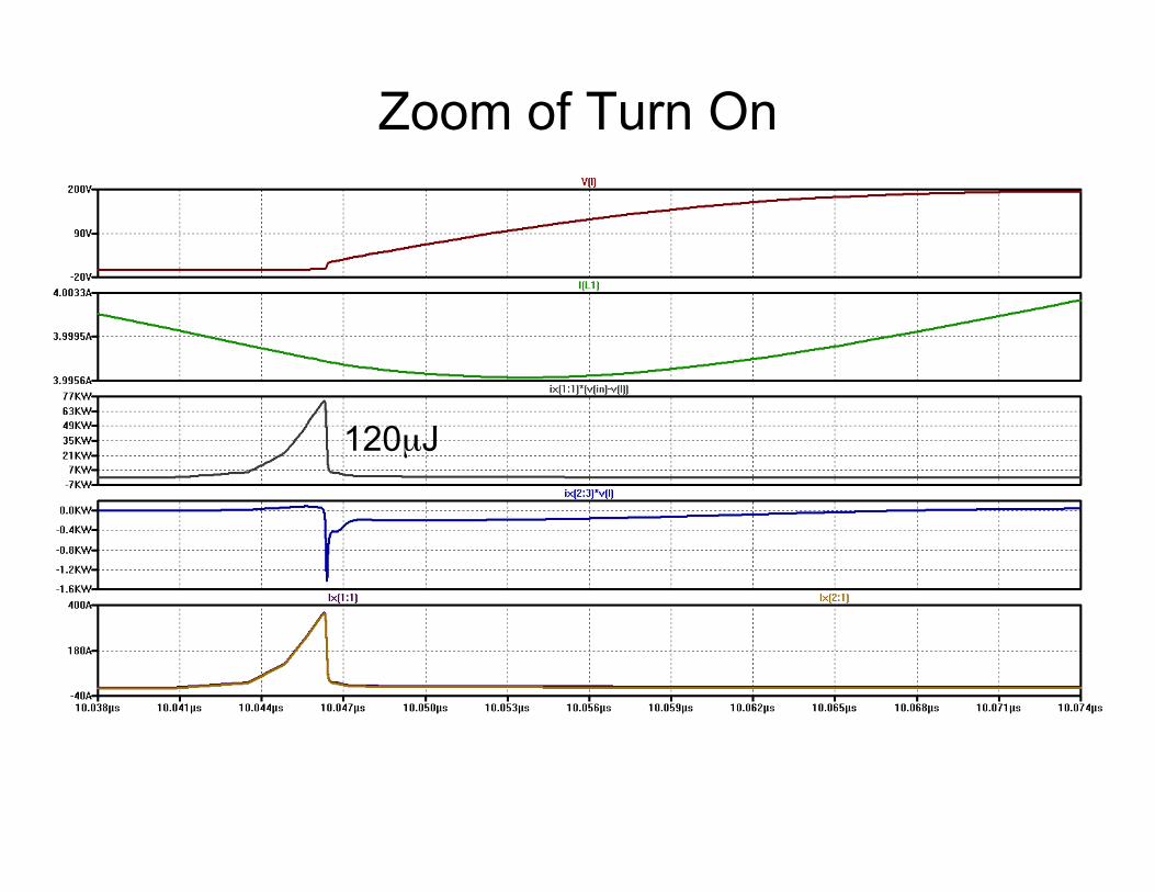
Zoom of Turn On
120µJ
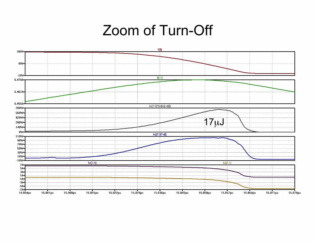
Zoom of Turn-Off
17µJ
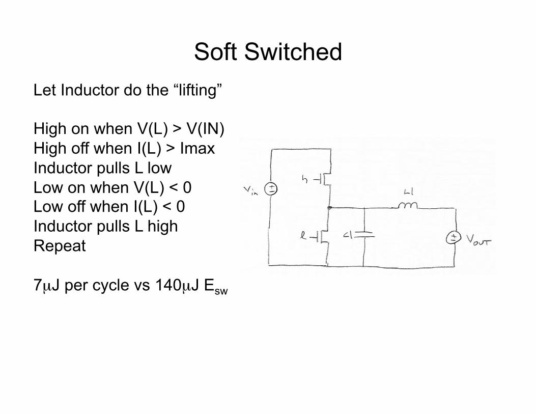
Soft Switched Let Inductor do the “lifting” High on when V(L) > V(IN) High off when I(L) > Imax Inductor pulls L low Low on when V(L) < 0 Low off when I(L) < 0 Inductor pulls L high Repeat 7µJ per cycle vs 140µJ Esw

Soft Switched Waveforms
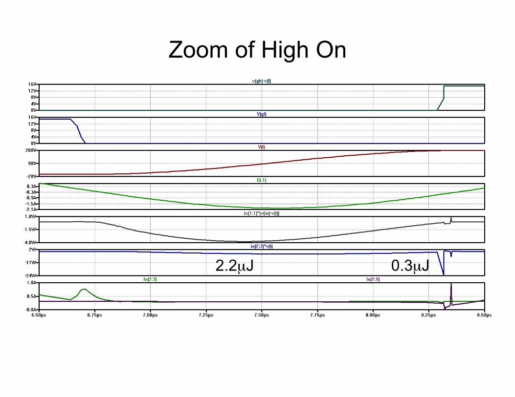
Zoom of High On
0.3µJ 2.2µJ

Zoom of High Off
4.8µJ

Power Measurement
Hard Switched!ph: AVG(ix(1:1)*(v(in)-v(l)))=14.283 FROM 1e-005 TO 0.004!pl: AVG(ix(2:1)*v(l))=0.577092 FROM 1e-005 TO 0.004!pt: ph+pl=14.8601!!Soft Switched!ph: AVG(ix(1:1)*(v(in)-v(l)))=0.420356 FROM 7.5e-006 TO 0.000352!pl: AVG(ix(2:1)*v(l))=0.388059 FROM 7.5e-006 TO 0.000352!pt: ph+pl=0.808416!!

Controlling the Soft-Switched Buck • Current-mode control
– Control high-side “on-time” (peak current) – Other three times are triggered by voltage/current
• High ripple current – critical conduction mode
• Gives variable frequency – Lower currents give higher frequency
• Switch to hard-switched PFM at very low currents

A CCM Boost Converter with Soft Switching

Waveforms
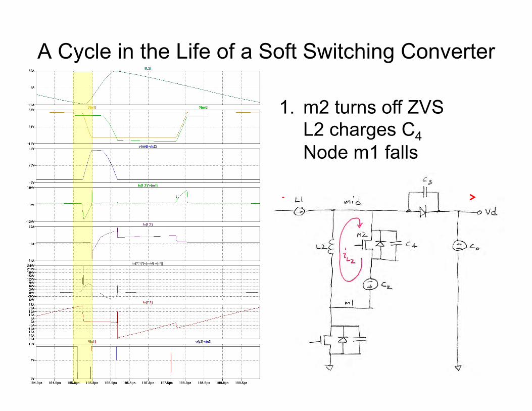
A Cycle in the Life of a Soft Switching Converter
1. m2 turns off ZVS L2 charges C4 Node m1 falls

A Cycle in the Life of a Soft Switching Converter
2. m1 turns on ZVS/ZCS L2 slope reverses
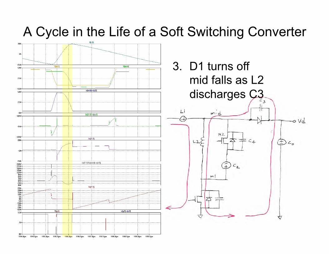
A Cycle in the Life of a Soft Switching Converter
3. D1 turns off mid falls as L2
discharges C3

A Cycle in the Life of a Soft Switching Converter
4. m2 turns on ZVS/ZCS L2 slope reverses
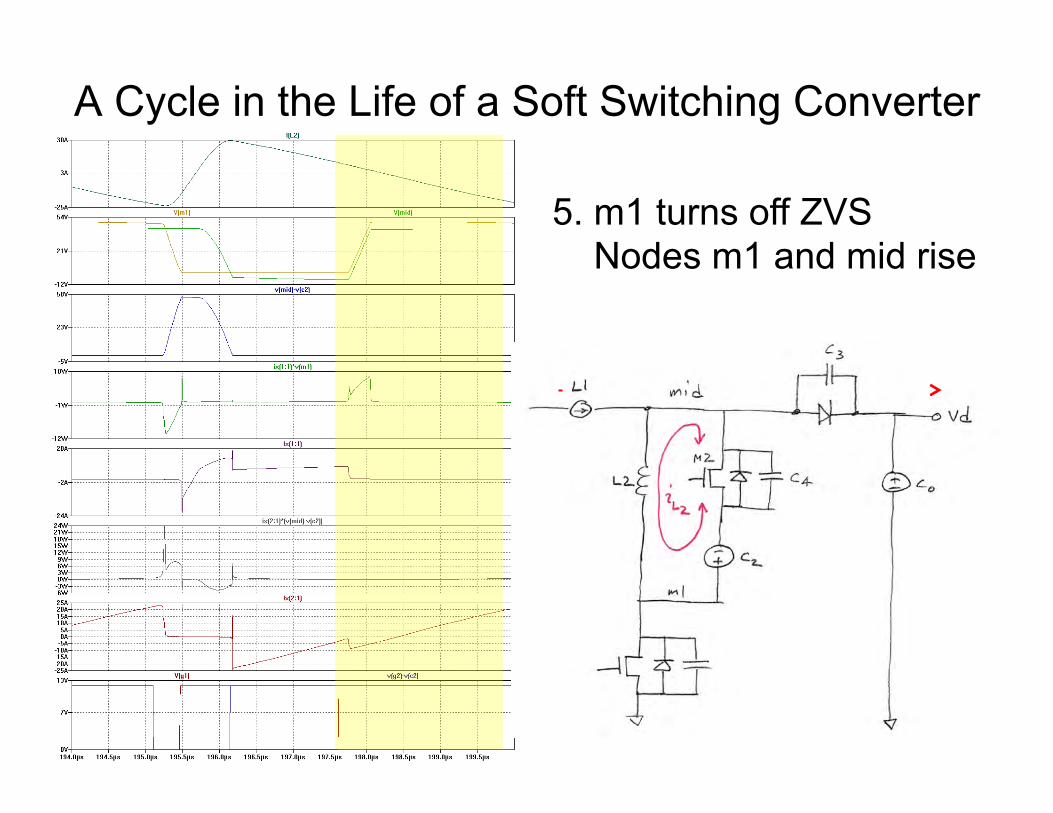
A Cycle in the Life of a Soft Switching Converter
5. m1 turns off ZVS Nodes m1 and mid rise

0.42W FET Losses (vs 18.2W, 43x)
pm1: AVG(ix(1:1)*v(m1))=0.0827113 FROM 0.0001 TO 0.0002!pm2: AVG(ix(2:1)*(v(mid)-v(c2)))=0.332469 FROM 0.0001 TO 0.0002!
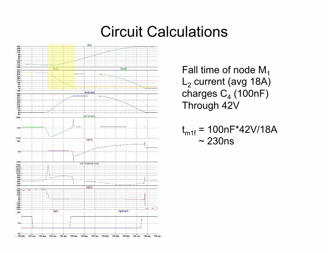
Circuit Calculations
Fall time of node M1 L2 current (avg 18A) charges C4 (100nF) Through 42V tm1f = 100nF*42V/18A ~ 230ns

Circuit Calculations
Time to D2 turn off Time for IL2 to ramp from -12A to +7A Slope is Vd/L2 td2off = I*L/V = 19A*0.5u/42V ~230ns

Circuit Calculations
Time for mid to fall L2 discharges C3 and C4 With portion of current not Used to sink L1 tmidf = CV/I = (C3+C4)(42)/(IL2-IL1) = 150nF(42)/(11) ~ 570ns
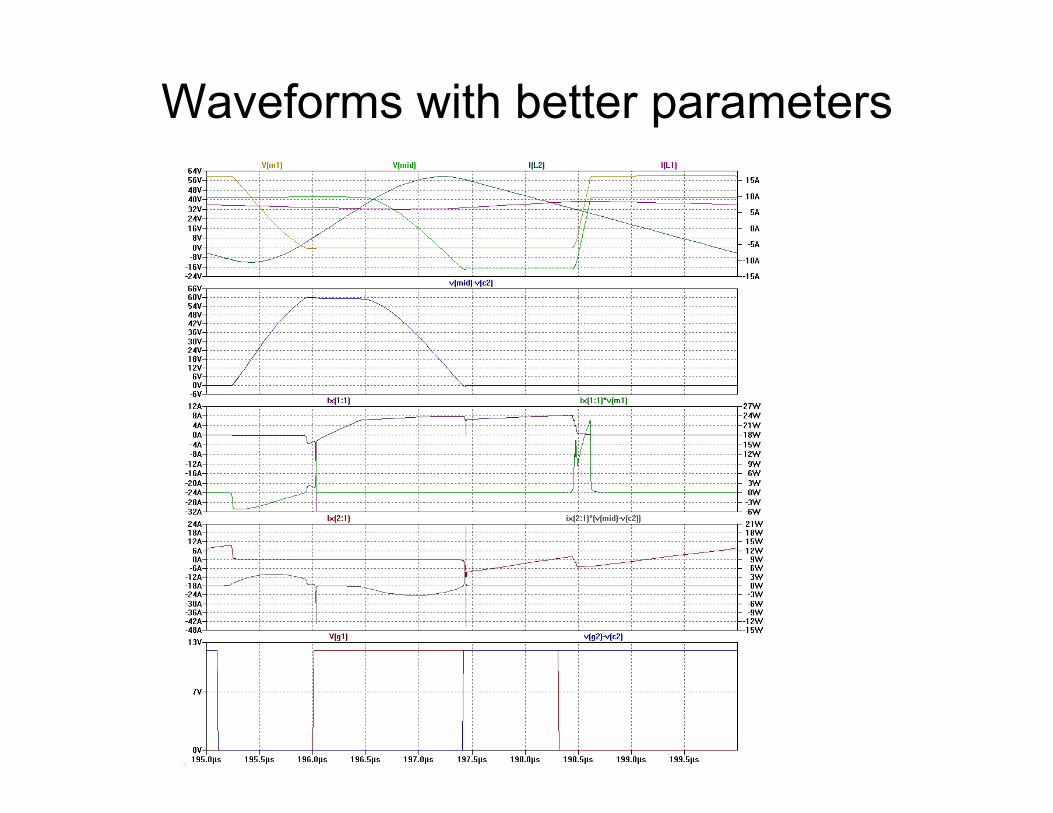
Waveforms with better parameters

Soft Switching • Largely eliminates switching loss in FETs • Adds components
– L2, M2, C2, and C3
• Adds conduction loss due to “resonant” current – L2 current in L2 and M2
• Requires precise timing – Narrow windows for M1 on and M2 on after M2 off
• One step to turn a 70% efficient converter into a 95% efficient converter

Summary of Soft Switching • Switch FETs (or IGBTs) only with zero voltage, zero currrent, or
both • Lossless snubbers
– Series inductance to give ZCS and/or parallel capacitance to give ZVS – recycle energy in L and C
• Resonate main inductor – Requires reversal of current to pull switching node “up” – Requires critical conduction mode – Gives variable switching frequency – Can be applied to other topologies – Requires higher (and negative) currents
• Active clamp circuit – LC tank controlled by aux switch in series with main switch – Requires higher currents and voltages

In Upcoming Lectures • Inverters • Power Factor • Batteries • Guest Lectures from Tesla and Enphase