ee 354 modern communication systems amplitude modulation ... 11-13 - am... · ee 354 modern...
TRANSCRIPT

1
1
EE 354Modern Communication Systems
Amplitude Modulation
Spring 2015
Instructor: C. R. Anderson
2
A Problem…
MIDN A, in Annapolis, has a 6 MHz analog signal that he wants to send to his friend MIDN B, who is vacationing in Outer Mongolia. The transmission will use a satellite as a relay. But, satellite communications cannot support a baseband 6 MHz signal, since this frequency will be refracted off the ionosphere. The satellite requires MIDN A’s transmission be 5 GHz.

2
3
Ok, let’s just go terrestrial…
Suppose two midshipmen are yakking on their phones, and each is generating a PCM signal that has a bit rate of 64 kbps. The midshipmen would like to share a channel that has a bandwidth of 128,000 Hz. They might consider sharing on a frequency division basis, where MIDN A is assigned the lower half of the 128,000 Hz channel and MIDN B is assigned the upper half… But how does MIDN B shift his frequency to the upper half?
4
Bottom Line…
Definition: Modulation: The process by which some characteristic of a carrier is varied in accordance with the modulating wave.
We often have to shift the frequency range of our signalto a different range of frequencies. This shifting isaccomplished by modulation. .

3
5
Carrier Modulation – 3 ways to impart information onto a sinusoidal carrier
-0.5
0
0.5
1
1.5
2
2.5
Changing the amplitude of the sine wave as time passes…
I could change the amplitude, increasing it and decreasing it so as to make it represent some data….This is called AMPLITUDE MODULATION
sin(2 )cA f t
6
Carrier Modulation – 3 ways to impart information onto a sinusoidal carrier
Changing the frequency of the sine wave as time passes…
I could change the frequency, increasing it and decreasing it so as to make it represent some data….This is called FREQUENCY MODULATION
sin(2 )cA f t

4
7
Carrier Modulation – 3 ways to impart information onto a sinusoidal carrier
sin(2 )cA f t
I could change the phase of the carrier, increasing it and decreasing it so as to make it represent some data…. This is called PHASE MODULATION
Data Pattern: 1 1 0 1 0 0 1
8
DSB-SC Amplitude Modulation
m t
s t
cf
Information signal – analog baseband
Modulated Signal – analog bandpass
Carrier Frequency – high frequency sinusoid
Definition: Information signal, modulated signal, and carrier frequency are defined as:
fC fC+ fmfC- fm
Lower Sideband Upper Sideband
fC fC+ fmfC- fm
Frequency Spectrum of a DSB-SC AM Signal
1 12 2cos(2 )c c cs t m t f t S f M f f M f f
12 cM f f
12 cM f f
M f
Recall: When multiplying a time function by a pure sinusoid, the result is to shift the original spectrum both up and down in frequency and multiply the amplitude by half.

5
9
DSB-SC AM Modulation
Note 1: Suppressed Carrier, nothing appears at fc.
Note 2: Transmitted bandwith is given by (AM is bandwidth inefficient)
Note 3: DSB-SC isn’t a useful way to communicate – it requires a synchronous receiver.
fC fC+ fmfC- fm
Lower Sideband Upper Sideband
fC fC+ fmfC- fm
1 12 2c cS f M f f M f f
12 cM f f
12 cM f f
M f
max2BW f
maxf
max2BW f
10
Creation and Recovery of DSB-SC AM
m t
cs t
s t
To modulate AM signals, we use a device known as a mixer.
cos 2
c
c
s t m t s t
s t m t f t
To demodulate AM signals, we use a mixer and LPF (Requires Phase Sync.).
m t
cs t
s t
ˆ cos 2 cos 2 cos 2c c cm t s t f t m t f t f t
2
2 1 12 2
ˆ cos 2
Note: cos cos 2
cm t m t f t
A A
1 12 2
ˆ cos 4 cm t m t m t f t
1 12 2
ˆ cos 4 cm t m t m t f t Rejected byLPF
12m t m t m t

6
11
Example Problem – Lathi 4.1 (Handout)
Given: A baseband signal is of the form: .
This signal AM modulates a high-frequency carrier.
Find: Sketch the resulting DSB-SC AM signal in both the time-domain and frequency domain.
Note: This particular example is referred to as tone modulation because the underlying modulating signal is a pure sinusoid (or tone).
cos 2 mm t f t
12
Example Problem Solution
The spectrum of the baseband signal is given by: m t
12 m mM f f f f f
In the time domain we have:
1
2
cos 2
cos 2 cos 2
cos 2 cos 2
c
m c
c m c m
s t m t f t
s t f t f t
s t f f t f f t
% Setup system parametersfc = 200; % Carrier Freq fm = 10; % Message Freq % Setup timebase fs = 10e3; % Sampling Freq Tend = 0.2; % Stop Time t = 0:1./fs:Tend; % Time % Generate the AM Signal m = cos(2.*pi.*fm.*t); s = m.*cos(2.*pi.*fc.*t);
0 0.02 0.04 0.06 0.08 0.1 0.12 0.14 0.16 0.18 0.2-1
-0.5
0
0.5
1
time (sec)
Am
plit
ud
e (V
)
DSB-SC AM Time Domain
We can plot this in Matlab, and observe the following:

7
13
Example Problem Solution
In the frequency domain we have:
1 12 2
1 14 4
c c
c m c m c m c m
S f m f f m f f
S f f f f f f f f f f f f f
14
A better version of AM: DSB-TC
fC fC+ fmfC- fm
Lower Sideband Upper Sideband
carrier
fC fC+ fmfC- fm
m t
cs t
s t
1 1 1 1
2 2 2 2
cos 2 c
c c c c
s t A m t f t
S f A f f A f f M f f M f f
M f
Transmit a tone carrier along with the AM modulated message signal.
max2BW f

8
15
AM Modulation Envelope – Two Cases
cos 2 cs t A m t f t
The quantity forms an envelope that bounds the amplitude of the carrier.
A m t
To illustrate
• Sketch .
• Sketch .
• Fill in carrier in between.
A m t A m t
Easily recoverable
Crossover Distortion
16
DSB-TC AM in the time domain
carrier
envelope
carrier amplitude
To ease analysis, rewrite in terms of amplitude-normalized message signal and modulation index .
m t
1 cos 2 cs t A m t f t pm
A cos 2p mm t m f t
Criteria for Envelope Detection: 0 1

9
17
AM Envelope Example (Lathi 4.3)Given: Suppose
Find: Sketch the resulting AM Signal if
cos 2 mm t b f t
bb A
A Note:
0.5
cos 2 mm t A f t
1 cos 2 cos 2m cs t A f t f t
18
AM Envelope Example (Lathi 4.3)Given: Suppose
Find: Sketch the resulting AM Signal if
cos 2 mm t b f t
bb A
A Note:
1.0
cos 2 mm t A f t
1 cos 2 cos 2m cs t A f t f t

10
19
AM Power and Efficiency
Define power efficiency as: s
C s
Psignalpower
total power P P
A carrier makes it easier to demodulate the incoming signal, but we pay a price in terms of efficiency.
Some of the transmitted power is being used to broadcast a pure sinusoid which does not convey any information.
Assuming tone modulation, expand the AM equation:
2 2
Carrier USB=UpperSideband LSB=LowerSideband
cos 2 cos 2 cos 2p pm m
c c m c ms t A f t f f t f f t
2
22
2
2
2 8
p
C
m
pUSB LSB
AP
mP P
Note:Power in Carrier:
Power in Sidebands:
20
AM Power and Efficiency
If we rewrite the above expressions in terms of the modulation index:
22
2 222
28 8
2
8 2 8 22
AAs
A A AAC s
P
P P
Thus:
2 2
2
2 8
A
USB LSB
AP P
Note That: As the index of modulation decreases, the efficiency will also decrease. In fact, for sinusoidal modulating signals and evelope detection, we find that:
2 2
Carrier USB=UpperSideband LSB=LowerSideband
cos 2 cos 2 cos 2A Ac c m c ms t A f t f f t f f t
33% 0 1for

11
21
AM ExampleGiven: AM Transmitter, 1 kW unmodulated output power, 50Ω load.
5V sinusoidal input to the modulator gives the amplitude of each sideband to be 40% of the amplitude of the carrier.
Find: (a) What is the modulation index?(b) What is the power in the Carrier, USB, and LSB(c) What is the efficiency of the AM Transmitter.
s t Gs t s t
22
Recovering the Message: Envelope Detector
Observe: If we can trace out the Envelope of the AM signal, we can effectively recover the underlying information signal.
tm r t envr t lpfr t
12
23
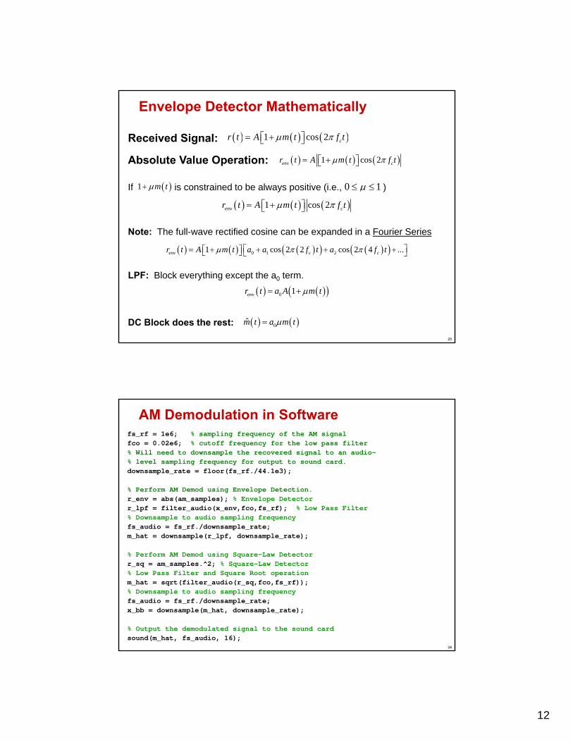
Envelope Detector Mathematically
1 cos 2 cr t A m t f t Received Signal:
Absolute Value Operation: 1 cos 2env cr t A m t f t
If is constrained to be always positive (i.e., ) 1 m t 0 1
1 cos 2env cr t A m t f t
Note: The full-wave rectified cosine can be expanded in a Fourier Series
0 1 21 cos 2 2 cos 2 4 ...env c cr t A m t a a f t a f t
LPF: Block everything except the a0 term.
0 1envr t a A m t
DC Block does the rest: 0m t a m t
24
AM Demodulation in Softwarefs_rf = 1e6; % sampling frequency of the AM signalfco = 0.02e6; % cutoff frequency for the low pass filter% Will need to downsample the recovered signal to an audio-% level sampling frequency for output to sound card.downsample_rate = floor(fs_rf./44.1e3);
% Perform AM Demod using Envelope Detection.r_env = abs(am_samples); % Envelope Detectorr_lpf = filter_audio(x_env,fco,fs_rf); % Low Pass Filter% Downsample to audio sampling frequencyfs_audio = fs_rf./downsample_rate; m_hat = downsample(r_lpf, downsample_rate);
% Perform AM Demod using Square-Law Detectorr_sq = am_samples.^2; % Square-Law Detector% Low Pass Filter and Square Root operationm_hat = sqrt(filter_audio(r_sq,fco,fs_rf));% Downsample to audio sampling frequencyfs_audio = fs_rf./downsample_rate; x_bb = downsample(m_hat, downsample_rate);
% Output the demodulated signal to the sound cardsound(m_hat, fs_audio, 16);

13
25
Frequency Division MultiplexingConsider: MIDN A likes listening to old-fashioned grunge music. MIDN B is more of a modern music fan. How do we satisfy their listening desires?
We could TDM music (0900 Grunge Hour; 1000 Alternative; 1100 Classical), or we could establish multiple stations on different frequencies and multiplex them in the Frequency Domain.
Note: Stations transmit their signals simultaneously in time, but are separated in frequency.
26
Example: FDM Across the AM Radio Band
1 2500 , 510 ,..., 1700
Nc c cf kHz f kHz f kHz