ee 201704 cover mech db - evaluation engineering · pdf file2 e april 2017 editorial np...
TRANSCRIPT

EE_201704_COVER_MECH_dB.indd COVERIIEE_201704_COVER_MECH_dB.indd COVERII 3/9/2017 3:59:49 PM3/9/2017 3:59:49 PM

Visit www.rsleads.com/704ee-005
EE201704-AD_Pickering_50730.indd COVERIIEE201704-AD_Pickering_50730.indd COVERII 3/7/2017 3:08:31 PM3/7/2017 3:08:31 PM

evaluationengineering.comApril 2017 1
April 2017, Vol. 56, No.4
EE-EVALUATION ENGINEERING (ISSN 0149-0370). Published monthly by NP Communications, 2477 Stickney Point Rd., Ste. 221-B, Sarasota, FL 34231. Subscription rates: $176 per year in the United States; $193.60 per year in Canada/Mexico; International subscriptions are $224.40 per year. Current single copies, (if available) are $15.40 each (U.S.); $19.80 (international). Back issues, if available, are $17.60 each (U.S.) and $22 (international). Payment must be made in U.S. funds on a branch of a U.S. bank within the continental United States and accompany request. Subscription inquiries: [email protected].
Title® registered U.S. Patent Offi ce. Copyright© 2017 by NP Communications LLC. All rights reserved. No part of this publication may be reproduced or transmitted in any form or by any means, electronic or mechanical, including photocopy, recording, or any information storage-and-retrieval system, without permission in writing from the publisher.
Offi ce of publication: Periodicals Postage Paid at Sarasota, FL 34276 and at additional mailing offi ces. Postmaster: Send address changes to EE-EVALUATION ENGINEERING, P.O. BOX 17517, SARASOTA FL 34276-0517
Written by Engineers…for Engineers evaluationengineering.com
@EE_Engineers
www.facebook.com/EvaluationEngineering
C O N T E N T S
C O M M U N I C AT I O N S T E S TSPECIAL REPORT
5G Development 6 Pivotal year sees standardization
proceedBy Rick Nelson, Executive Editor
Components26 All-digital phase-locked loop offers
sub-mW power consumptionBy Rick Nelson, Executive Editor
I N S T R U M E N TAT I O NSPECIAL REPORT
Oscilloscopes12 Triggering morphs to match
application needsBy Tom Lecklider, Senior Technical Editor
Instrumentation18 Boosting measurement capability
from pocket to benchtopBy Rick Nelson, Executive Editor
Technology Insights32 So many ways to stick layers together
By Tom Lecklider, Senior Technical Editor
S O F T WA R E
Asset Management24 Keeping track of what you’ve got
By Tom Lecklider, Senior Technical Editor
E M C / E M I / R F I
EMC Product Focus28 Ensuring high-quality power for
today’s product designsBy Rick Nelson, Executive Editor
D E PA R T M E N T S
2 Editorial
4 EE Industry Update
30 EE Product Picks
31 Index of Advertisers
01_EE_201704_TOC_FINAL.indd 101_EE_201704_TOC_FINAL.indd 1 3/9/2017 3:12:12 PM3/9/2017 3:12:12 PM
April 2017evaluationengineering.com2
EDITORIAL
NP COMMUNICATIONS LLC2477 Stickney Point Rd., Suite 221BSarasota, Florida 34231Phone: 941-388-7050•Fax: 941-388-7490
Publishers of this magazine assume no responsibility for statements made by their advertisers in business competition, nor do they assume responsibility for statements/opinions, expressed or implied, in the columns of this magazine.
Printed in the U.S.A.
evaluationengineering.com
EDITORIALEXECUTIVE EDITOR Rick Nelsone-mail: [email protected]
MANAGING EDITOR Deborah Beebee-mail: [email protected]
SENIOR TECHNICAL EDITOR Tom Lecklidere-mail: [email protected]
PRODUCTIONAD CONTRACTS MANAGER Laura Moulton
e-mail: [email protected]
AD TRAFFIC MANAGER Denise Mathewse-mail: [email protected]
BUSINESSPRESIDENT Kristine Russell
e-mail: [email protected]
PUBLISHER Jim Russelle-mail: [email protected]
ASSOCIATE PUBLISHER Michael Hughese-mail: [email protected]
MARKETING DIRECTOR Joan Sutherland
ADVERTISINGWEST
Michael Hughes Phone: 805-529-6790e-mail: [email protected]
EASTBlake Holton or Michelle Holton
Phone: 407-971-6286 or 407-971-8558e-mail: bholton@cfl .rr.com
mmholton@cfl .rr.com
CIRCULATIONSUBSCRIPTIONS / BACK ISSUES
e-mail: [email protected]
LIST RENTALS Laura Moulton e-mail: [email protected]
EPRODUCT COORDINATOR Mary Haberstroh e-mail: [email protected]
REPRINTS Evelyn Dodgee-mail: [email protected]
EE-EVALUATION ENGINEERING is available by free subscription to qualifi ed managers, supervisors
and engineers in the electronics and related industries.
FOUNDER A. VERNER NELSONe-mail: [email protected]
Moore’s Law faces increasing challenges as the ability to shrink transistors encoun-ters physical and economic limits. In fact, last summer the Semiconductor Indus-
try Association released the last International Technology Roadmap for Semiconduc-tors (albeit it does look 15 years ahead). “For a quarter-century, the roadmap has been an important guidepost for evaluating and advancing semiconductor innovation,” said John Neuffer, SIA president and CEO, at the time of the release. “The latest and fi nal installment provides key fi ndings about the future of semiconductor technology and serves as a useful bridge to the next wave of semiconductor research initiatives.”
If it’s becoming impractical to shrink the transistors, perhaps an alternative research initiative would be to address shrinking the packages they go into. Following this line of reasoning, efforts are underway to continue driving the semiconductor industry forward.
One such initiative is the Heterogeneous Integration Roadmap, sponsored by orga-nizations including the IEEE Components, Packaging, and Manufacturing Technology Society and SEMI. A technical session at the International Test Conference last fall ad-dressed the topic, as I noted in my editorial in January.
Also last fall, the MicroElectronics Packaging and Test Engineering Council (MEPTEC) addressed the topic at its 2016 Semiconductor Packaging Roadmap Sym-posium, at which MEPTEC said it was initiating collaboration with Heterogeneous Integration Roadmap supporters. Among the symposium participants, Smoltek, an 11-year-old startup that spun out of Chalmers University, represented nanotechnology as what it called “a substantial option” for the future of semiconductors.
“The bottom line is that there is a strong need for a technological shift from the trend of scaling the transistors to the reduction of the size of an electronic package,” accord-ing to a Smoltek white paper. In pursuit of package-size reduction, the company spe-cializes in the development of nanostructure fabrication technology to solve advanced materials engineering problems for advanced semiconductor packaging applications.
Specifi cally, Smoltek’s Tiger carbon-nanostructure-based assembly platform sup-ports stacking bare dies on each other or bonding them to a substrate (interposer) or carrier (lead frame) using arrays of nanostructure-enabled metallic pillars. The tech-nology enables the integration of components including standard ICs, ASICs, FPGAs, memories, and microcontrollers as well as the embedding of additional functionality such as energy storage in the form of solid-state supercapacitors. The platform, the company estimates, offers tenfold to a hundredfold 3D shrinkage compared with es-tablished bump-and-pillar technologies.
In a recent phone interview, Anders Johansson, CEO of Smoltek, described the MEPTEC symposium as one of many such events in which his company participates. He cited the symposium’s “interesting focus on the heterogeneous fi eld where we see our technology fi tting so well”—particularly with regard to integrating several die into one advanced package, as in SiP technology. He said the company has demonstrated integrated capacitors on an interposer, thermal interface materials, and microbumps. A key achievement for the company has been to reduce the growth temperature for the conductive carbon nanostructures to below 390°C, making the technology compatible with CMOS processes.
Johansson said he has spent more than six years at Smoltek working on commercial-ization of the technology, which is protected by patents, including a European patent granted in February. He said he has seen a signifi cant increase in interest in the technol-ogy over the last year and a half. The company’s goal is to license its IP and support the integration of its processes. “We have clear ambition to have our fi rst license agree-ment signed this year,” he said.
Whatever the outcome of specifi c commercial platforms and organizational initia-tives, it’s encouraging to see companies and organizations supplant the guidance to-ward the semiconductor industry’s future once provided by the ITRS
Shrinking packages if not transistors
RICK NELSON
Executive Editor
Visit my blog: www.evaluationengineering.com/ricks-blog/
02_EE_201704_Editorial_MECH_dB.indd 202_EE_201704_Editorial_MECH_dB.indd 2 3/9/2017 8:39:41 AM3/9/2017 8:39:41 AM

rf/microwave instrumentation Other ar divisions: modular rf receiver systems ar europe
USA 215-723-8181. For an applications engineer, call 800-933-8181.
www.arworld.usDownload the AR RF/Microwave Mobile App: www.arworld.us/arApp
ISO 9001:2008Certified
We don’t just build great products. We build great products that last.
Features & Benefits For These Rugged Amplifiers Are:
To learn more, visit www.arworld.us/pulsedamps or call us at 215-723-8181.
Why AR Solid State Pulsed Amplifiers Should Be On Your Radar
Visit www.rsleads.com/704ee-001
EE201704-AD_AR-RF.indd 3EE201704-AD_AR-RF.indd 3 3/7/2017 3:05:23 PM3/7/2017 3:05:23 PM

April 2017evaluationengineering.com4
INDUSTRYUPDATE
$120 millionRFID sensor market in 2022
$980 millionRFID sensor market in 2027
Source: IDTechEx
$339 billionGlobal semiconductor sales in 2016
Source: Semiconductor
Industry Association
10.3%Growth in global shipments of
motion-control products in 2016
$3.3 billionTotal motion-control product
shipments in 2016Source: Motion Control
& Motor Association
€108 millionFlemish government’s annual grant to imec
Source: imec
300 millionExpected cellular V2X
global subscriptions by 2030, initially through LTE-V2X
Source: ABI Research
For more on these and other news items, visit www.evaluationengineering.com/category/industry-update/
Courtesy of SEMI
AR expands product line with new SunAR RF Motion division
AR RF/Microwave Instrumentation is expanding its product line with the ad-dition of the SunAR RF Motion division. While new to the AR family, the SunAR RF Motion products are familiar to many professionals in the EMC and wireless industries.
Formerly known as Sunol Sciences, the Dublin, CA-based enterprise has built a reputation for providing reliable, high-performance, and high-quality products, the company said.
The SunAR RF Motion product line includes precision positioners for EMC testing, antenna measurements, and OTA testing; antennas for EMC testing and distributed antenna systems; robotic
test platforms; and reverberation system design and stirrers for EMC, shielding effectiveness, and OTA testing.
SEMI appoints Ajit Manocha president and CEO
SEMI, the global association con-necting and repre-senting the world-wide electronics m a n u f a c t u r i n g supply chain, has announced the ap-pointment of Ajit Manocha as its
president and CEO. He succeeds Denny McGuirk, who announced his intention to retire last October. The SEMI board of directors conducted a comprehensive search, selecting Manocha, an indus-try leader with more than 35 years of global experience in the semiconductor industry. Manocha began his new role on March 1 at SEMI’s new Milpitas, CA, headquarters.
“Ajit has a deep understanding of our industry’s dynamics and the inter-dependence of the electronics manu-facturing supply chain,” said Y.H. Lee, chairman of SEMI’s board of directors. “From his early days developing dry etch processes at AT&T Bell Labs, to running global manufacturing for Philips/NXP, Spansion, and, as CEO of GLOBALFOUNDRIES, Ajit has been formative to our industry’s growth. Ajit is the ideal choice to drive our SEMI 2020 plan and beyond, ensuring that SEMI provides industry stewardship and engages its members to advance the interests of the global electronics manu-facturing supply chain.”
Keysight, ZTE collaborate on 5G commercial predeployment
Keysight Technologies has announced that it is collaborating with ZTE to assist in the test and measurement of critical 5G key technologies, including mmWave communications, massive MIMO, and base transceiver station (BTS) beam-forming prototypes. Keysight will help ZTE accelerate 5G product time to market by providing industry-leading products and solutions—for example, UXA mmWave signal analyzers, AXIe modular ultrabroad-bandwidth signal generation and analysis systems, and system-level prototype solutions.
ZTE is a telecommunication solution provider that is a participant in and con-tributor of 5G communications. It is one
of the companies in the fi rst group that completed the China 5G Experimental Trials in phase I and is accredited by IMT2020(5G) Promotion Group with the offi cial certifi cate of 5G technologies experiments. ZTE’s mmWave 5G BTS prototype now is under test in the China 5G Experimental Trials phase II.
Rudolph receives multisystem order for advanced memory ramp
Rudolph Technologies announced that a memory manufacturer in Asia has placed orders totaling over $8 million for process-control equipment to sup-port the ramp of its latest high-perfor-mance stacked memory devices. The equipment spans front- and back-end applications. It includes MetaPULSE metrology systems for plating and etch control and NSX 330 systems for two- and three-dimensional inspection and metrology throughout the back-end process. The systems are scheduled to ship in the fi rst quarter of this year.
AT4 wireless expands its testing capability for Bluetooth 5
AT4 wireless, a DEKRA company, has announced the expansion of capabilities in its Bluetooth Qualifi cation Testing Facilities, after adding Bluetooth 5 to its portfolio.
On Dec. 6, 2016, the Bluetooth SIG adopted the Bluetooth 5 specifi cation. With the launch of Bluetooth 5, Blue-tooth technology continues to evolve to meet the needs of the industry as the global wireless standard for simple, secure connectivity. With 4x range, 2x speed and 8x broadcasting message capacity, the enhancements of Bluetooth 5 focus on increasing the functionality of the Bluetooth technology for the IoT market needs.
Qualcomm and TDK announce RF360 Holdings joint venture
Qualcomm and TDK have completed of the previously announced joint venture under the name RF360 Holdings Singa-pore PTE. Ltd. (RF360 Holdings). The joint venture will enable Qualcomm’s RFFE Business Unit to deliver RF front-end (RFFE) modules and RF fi lters into fully integrated systems for mobile devices and fast-growing business seg-ments, such as those involving the Inter-net of Things, automotive applications, and connected computing. The business being transferred constitutes a part of the TDK SAW Business Group activities.
04-05_EE_201704_IndUpdate_MECH_dB.indd 404-05_EE_201704_IndUpdate_MECH_dB.indd 4 3/9/2017 12:03:59 PM3/9/2017 12:03:59 PM

evaluationengineering.comApril 2017 5
INDUSTRYUPDATE
Courtesy of Flann Microwave
IPC president and CEO to serve on the NAM CMA board of directors
IPC president and CEO John Mitchell has been elected to serve on the Na-tional Association of Manufacturers (NAM) Council of Manufacturing As-sociations (CMA) board of directors.
The CMA is made up of more than 260 manufacturing trade associations that work together on behalf of manufactur-ing in the United States. CMA members serve an important role in working with the NAM to unite the manufacturing community, and ultimately the broader business community, on the common goals of strengthening the industry for more jobs, investment, and innovation.
“I am honored to serve as a director of the NAM’s Council of Manufactur-ing Associations and am eager to work with other manufacturing leaders to strengthen the voice for advanced manufacturing in the United States,” said Mitchell. “With a new Administra-tion and Congress, we face new oppor-tunities to work together to shape poli-cies that will help grow the electronics industry and create jobs across many industry sectors, strengthening the overall economy.”
SET, Konrad Technologies team up on ADAS sensor fusion and HiL
Due to continuously rising demands on mobility and autonomous driving, integrated and automated testing solu-
tions are needed for advanced driver assistance systems (ADAS). The com-bination of ADAS sensor fusion with a hardware-in-the-loop (HiL) testing sys-tem is necessary to enable a new level of automated testing solutions in the automotive space. In response to this need, Konrad Technologies, based in Radolfzell, Germany, and SET, based in Wangen im Allgäu, Germany, are join-ing forces to develop custom testing systems for driver-assistance systems.
Together, the expertise on ADAS sensor fusion of Konrad Technologies GmbH and on HiL by SET GmbH form a complete, fl exible set of tools from de-sign to development, implementation, and validation to production. These synergies allow optimal solutions to be offered to shared customers. The agreement provides for collaboration between the two long-time National Instruments Alliance partners both on technical as well as strategic activities.
ACS Motion Control joins forces with PI
Motion-control and nanopositioning systems company PI (Physik Instru-mente) has announced the acquisition of 80% of the Israeli-based company ACS Motion Control, a developer and manufacturer of controllers and drives for multi-axis systems.
PI said that with this investment, it is better able to serve industrial cus-tomers with complete tailored systems
that can be easily integrated into a variety of automation environments. One such use is PI’s range of multi-axis air-bearing linear stages with magnetic direct drive that are suitable for preci-sion material processing, inspection systems, mounting applications, or digital printing. ACS will continue to be independent within the PI Group, the management will not change, and it will continue to supply existing customers.
EXFO and Rohde & Schwarz accelerate mobile-network troubleshooting
EXFO and Rohde & Schwarz have partnered to provide test-and-mea-surement solutions for onsite commis-sioning, maintenance, and trouble-shooting of mobile communications systems. EXFO and Rohde & Schwarz offer complementary solutions that combine optical and wireless technolo-gies to quickly locate and eliminate RF interference.
In modern mobile network stations, RF equipment continues to shift closer to the antennas. The equipment usu-ally is mounted just below the antenna to minimize cable loss. The intercon-nection between the RF equipment at the top of the tower and the baseband unit is bridged via fi ber-optic cabling—thereby increasing the necessity for both fi ber-to-the-antenna and over-the-air RF test-and-measurement technology.
Flann Microwave engineers celebrate IEEE 1785 waveguide standard
Flann Microwave said its engineers are celebrating the publication of a new three-part international standard that will defi ne how waveguides are used for decades to come.
The company said its team played a key role in the development of the new IEEE 1785 standard, which sets requirements for waveguides from 75 GHz to 3.3 THz. Previously, there was no internationally agreed standard for waveguides operating above 330 GHz.
The new standard is split into three parts: Part 1 (IEEE 1785.1:2012) defi nes the operating frequencies, dimensions, tolerances, and names for the waveguide; Part 2 (IEEE 1785.2:2016) provides three designs of the waveguide interface (fl ange) to guarantee alignment accuracy; and Part 3 (IEEE 1785.3:2016) describes how to assess the performance of a pair of waveguide interfaces.
The Flann team has been working with the IEEE 1785 working group since it was formed in March 2008, and the interface drawings in the new IEEE standard were produced by Flann mechanical engineers, the company reported.
04-05_EE_201704_IndUpdate_FINAL.indd 504-05_EE_201704_IndUpdate_FINAL.indd 5 3/9/2017 3:12:45 PM3/9/2017 3:12:45 PM
April 2017evaluationengineering.com6
Sponsored bySPECIAL REPORT 5G DE VELO PMENT
This year is shaping up to be a critical one for 5G, as several participants in 5G development have pointed out.
Efforts at standardization are continuing as the development of the multiple tech-nologies that might make up 5G proceeds. Other challenges center on frequency al-location and coexistence—with previous generation cellular technologies as well as with radar and satellite signals.
According to James Kimery, director, marketing, RF research/SDR at National Instruments, “2017 will be a pivotal year in the 5G trajectory as the worlds’ tele-communication infrastructure companies, silicon providers, service operators, and test-and-measurement companies fi nalize the specifi cations, conduct fi eld trials, and begin the commercialization process.”
“The major challenge facing 5G this year is that the standard will not be de-fi ned as a single wireless technology like its predecessors,” said Dr. Li-Ke Huang, research and technology director at Cob-ham Wireless. “It will, in fact, comprise a number of different services being deliv-ered to the end user across multiple access technologies and multilayer networks. 5G will effectively be a dynamic, coherent, and fl exible technological framework—and very different from the previous generations of wireless standards. It will provide a system that leverages a variety of technologies depending on the precise needs of the application, particularly as IoT becomes more prevalent.”
Ken Karnofsky, senior strategist, sig-nal processing applications, MathWorks, said, “In 2017, we expect to see 5G engi-neers focusing on development of cost-
effective massive MIMO and millimeter wave (mmWave) technologies to achieve high throughput with low power con-sumption, design of new waveforms to achieve greater spectral effi ciency, and rapid deployment of radio testbeds and prototypes to fi eld-test these 5G technologies.”
Reiner Stuhlfauth, technology market-ing manager, Rohde & Schwarz, offered a broad look at the topic. “From a global-political perspective, the key challenges in furthering 5G in 2017 are around stand-ardization and frequency allocation,” he said. “From a standardization perspec-tive, a lot of work remains with 3GPP Re-lease 15 throughout 2017 in order to meet the offi cial release of the specifi cation in June 2018. In addition, there are also some discrepancies between the ‘pre-5G’ specifi cations and trials underway and the 3GPP 5G specifi cations that need to be resolved.”
Larry Davis, national sales manager, 5G business development, Anritsu U.S., de-scribed some specifi c challenges. “When we talk about 5G, three big technology hurdles often dominate the conversa-tion—low latency of less than 1 ms, high data throughput of greater than 1 Gb/s, and support of massive connectivity to accommodate 50 billion new IoT devices by 2020,” he said.
Kimery at NI explained, “The 3GPP standardization body has defi ned two phases of 5G standards development, ap-propriately named Phase 1 and Phase 2. In 2017, the 3GPP will be driving to defi ne the fi rst unifi ed standard for Phase 1.” As this issue went to press in late February,
Pivotal year sees standardization proceedBy Rick Nelson, Executive Editor
Kimery expected that in March, the 3GPP would kick off the fi rst 5G work item with an expected completion in September 2018. “Although 5G Phase 1 otherwise known as 3GPP Release 15 is expected to complete in 2018, we should get a clear picture of what will be included in the standard throughout 2017 as researchers around the world take on the monumen-tal task of defi ning and standardizing each component of a new end-to-end net-work,” he said.
Davis at Anritsu said, “5G’s success will require disruptive technological in-novation in nearly all areas of the 4G network”—including the re-engineering of access networks, base stations, and wireline edge and core networks. “It is the scope of the required change—all interde-pendent upon the innovation of the oth-ers—that represents the biggest challenge of 5G,” he added.
“Some chief hurdles associated with 5G, however, are not technological in na-ture, but more economics driven,” Davis noted. “For example, if microwave and mmWave bands are to become economi-cally viable options versus emerging alternatives like LTE-U/LAA, test and component suppliers across the ecosys-tem need to address the signifi cant cost issues associated with high-frequency technologies.”
Nearly every participant in the mobile broadband ecosystem, including compo-nent and device manufacturers, network equipment manufacturers, wireline and wireless service providers, and applica-tions developers must introduce dis-ruptive new technologies to meet these
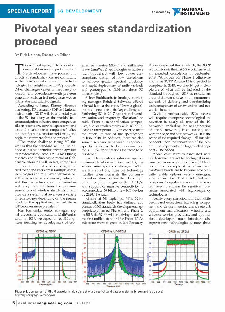
Figure 1. Comparison of OFDM waveform (blue traces) with three 5G candidate waveforms (green and red traces)Courtesy of Keysight Technologies
06-11_EE_201704_SpecRep-5G_MECH_dB.indd 606-11_EE_201704_SpecRep-5G_MECH_dB.indd 6 3/9/2017 2:23:41 PM3/9/2017 2:23:41 PM

evaluationengineering.comApril 2017 7
S PE C I A L R E P O R T - 5 G D E V E LO P M E N T
technical and economic goals, Davis said, adding, “With an unprecedented interde-pendence, they all collectively play a criti-cal role in not only delivering essential new technologies and capabilities (that is, beam steering and tracking and mmWave radios), but also reducing the overall cost of networks, UEs, and installation and maintenance processes.”
Huang at Cobham Wireless explained, “Taking into consideration the complexity of 5G, this year the industry will have to explore new and more sophisticated test-ing and validation techniques”—extend-ing from the chipset and radio antenna to the end-to-end network performance. He continued, “Other factors like air-interface architecture and the different frequency bands must be considered, but important emphasis should be placed on validating the user experience when run-ning new applications.”
Huang added, “The industry is keen to make 5G happen as soon as possible, and the only thing which could slow it down is the core technology and development cycle needed to take it from conception to reality. Market creation, the level of in-vestment, and technical direction are all converging and taking shape, so the real challenge for progressing 5G this year will be the compatibility of different sec-tions of the ecosystem.”
Stuhlfauth at Rohde & Schwarz noted that spectrum allocation and usage on a global and regional scale must be con-sidered and consolidated to minimize the complexity of RF front-end designs, signal processing, and so on. “Finally, 5G will coexist with LTE technology for many years to come, with LTE-Advanced coming out with many new and interest-ing features—for example, NB-IoT [Nar-rowBand IoT], LTE-V [LTE-Vehicle], LAA [Licensed-Assisted Access], and eMTC [enhanced Machine Type Communica-tion],” he said. “Companies that are in-volved with the design and production of mobile wireless devices will need to con-sider how to best optimize their resourc-es to support both technologies moving forward.”
Karnofsky at MathWorks commented on the role of engineers this year. “In the race to 5G, system engineers and ar-chitects must focus on accelerating in-novation and minimizing the valuable engineering time spent on programming, debugging, or building hardware realiza-tions of their design ideas,” he said. “This is particularly important when working with fast-changing pre-standardization communication protocols. The tools and workfl ows must support rapid design iterations and rapid deployment of new algorithms or design changes.”
Karnofsky added, “Massive MIMO and mmWave technologies will drive dra-
matic changes to the architecture of the radio front end. The expertise required to design the highly integrated 5G radio technology includes RF, antenna, DSP, control logic, hardware, and software—as well as a working knowledge of exist-ing standards. 5G researchers need new methods to verify that components will work together and eliminate the problems that lead to expensive hardware failures and project delays.”
A particular challenge relates to FPGAs. “A signifi cant hurdle for many teams is a lack of experience with FPGA development workfl ows and RTL imple-mentation of signal-processing and com-munications algorithms,” Karnofsky said. “For a typical R&D group that consists of engineers with strong signal-process-ing and algorithm-development back-grounds but relatively little experience with hardware implementation, it is often diffi cult to implement FPGA-based radio prototypes and testbeds without outside assistance.”
the 5G marketplace are being designed in the 6 GHz and above range. 6-GHz switch products for test and measurement are way too large and expensive to be practi-cal…. Vendors are looking at using solid-state, pin-diode, and other technologies, but again these possess linearity and sig-nal-integrity dilemmas as the frequency increases.”
5G coexistence5G coexistence is an area that Keysight Technologies is addressing. “Just a glance at today’s frequency allocations makes it clear that 5G technology will have to fi t into crowded, congested, and complex airwaves,” writes Greg Jue, systems en-gineer, in a Keysight white paper.1 “Even in this cramped space, demand for higher data throughput continues to grow—and this is why researchers continue to look for new ways to use the available spec-trum more effi ciently with evolutionary and revolutionary signal formats.”
Jue presents several waveform candi-dates:
•orthogonal frequency-division multi-plexing (OFDM), currently used in 4G;
•fi lter-bank multicarrier (FBMC); •universal fi ltered multicarrier (UFMC),
also called universal fi ltered OFDM (UF-OFDM); and
•generalized frequency-division multi-plexing (GFDM).
Figure 1 shows a comparison of OFDM (blue traces) with three candidate wave-forms, each with two different fi lter char-acteristics (green and red traces). In all cases, compared with OFDM the candi-date waveforms are likely to provide bet-ter results for adjacent users, Jue notes.
To further explore coexistence sce-narios, Jue describes a testbed consisting of 89600 VSA software, an N9030B PXA X-Series signal analyzer, SystemVue elec-tronic system-level software with a 5G baseband library (W1906EP) running on a high-performance embedded control-ler (M9537A) installed in the AXIe chassis (M9505A), and a two-channel M8190A 12-GS/s arbitrary waveform generator.
He goes on to present three case stud-ies: 5G coexisting with legacy wireless sig-nals, 5G coexisting with satellite signals, and LTE coexisting with radar signals.
“As 5G research and development con-tinues to mature, coexistence will be a cru-cial area of investigation whether the fo-cus is on the interaction between new and legacy waveforms or between commer-cial and military systems,” he concludes, noting that the testbed approach can be used in an R&D lab before fi eld tests on working systems.
Platform approachWhen it comes to specifi c products for 5G applications, NI employs a platform ap-
Sourabh Dhillon, who handles cor-porate development at startup Integra Devices, sees challenges emerging in building out the telecommunications infrastructure that will offer the high frequencies (for example, 28 GHz) neces-sary to achieve 5G’s promise of high data speed, high capacity, and low latency.
“Solid-state switches and relays used today, because of their small footprint, will be too much of a liability due to lin-earity and signal-integrity issues at high frequencies and power,” Dhillon said. “Electromechanical relays, although they can handle high power and frequency, are too large and expensive…. Even PCB ma-terial becomes a liability as passing high-frequency signals through it will exhibit loss. Thus, a new breed of RF/mmWave components must be developed to sup-port 5G’s new telecommunications infra-structure.”
Dhillon added, “The test and measure-ment industry will also face challenges in conjunction with 5G. All new products for
Figure 2. USRP-2945 quad receiver SDR deviceCourtesy of National Instruments
06-11_EE_201704_SpecRep-5G_FINAL.indd 706-11_EE_201704_SpecRep-5G_FINAL.indd 7 3/9/2017 3:13:16 PM3/9/2017 3:13:16 PM

April 2017evaluationengineering.com8
Sponsored bySPECIAL REPORT 5G DE VELO PMENT
proach that enables users to use one plat-form including hardware and software to focus on application areas critical to 5G networks spanning design and test. “Our SDR hardware coupled with LabVIEW system design software and LabVIEW Communications offers the fastest path for researchers to transition from a con-cept to a real working prototype,” said Kimery. “The faster a concept can be pro-totyped, the quicker an idea can transition to fi eld trials, standardization, and even-tually commercialization. NI has been enabling wireless researchers to achieve the prototyping phase much sooner even though the system challenges that 5G poses are formidable.”
NI’s platform approach enables users to create, for example, channel-sounding systems capable of making measurements in the mmWave and cmWave frequency ranges quickly. “Current approaches us-ing standard test-and-measurement tech-niques must collect voluminous amounts of data that must be ‘post processed’ to achieve an accurate picture of the chan-nel,” Kimery said. “Harnessing the power of FPGAs and real-time signal processing delivered by LabVIEW and our SDR plat-forms, researchers can measure results in ‘real time,’ virtually eliminating post pro-cessing. Another benefi t of this approach is that channel measurements can be made fast—within the coherence time of the channel—which challenges even the most sophisticated test and measurement instrumentation.”
In addition, said Kimery, “SDRs deliver a software-defi ned approach that maxi-mally leverages current state-of-the-art technologies such as FPGAs, multicore microprocessors, high-level synthesis tools and abstraction, and the latest A/Ds, D/As, and RF ICs. Because of our platform approach, we apply this same approach to 5G test as the products move from prototype to commercialization.”
MIMO application frameworkNI has announced several products tar-geting the 5G application space, includ-ing the MIMO application framework for LabVIEW Communications. This fully scalable architecture enables users to
prototype multi-antenna systems having from four to 128 elements at 20 MHz of bandwidth. The software includes a mix-ture of host/multicore microprocessor code as well as FPGA software to facilitate a fully real-time system. Because of the software is delivered in source code, users can start with a fully functional massive MIMO system and then integrate their ideas to observe the results and iterate.
In addition, NI last year announced what Kimery called the world’s fi rst soft-ware-defi ned radio (SDR) for mmWave research, prototyping, and deployment. “The mmWave Transceiver System, or MTS, offers engineers and scientists the fi rst off-the-shelf platform to transition the mmWave research to a working pro-totype—fast and effi ciently,” he said. “There are several challenges with utiliz-ing the mmWave spectrum for commu-nications, such as wider bandwidths to increase data rates and take advantage of the copious spectrum in those bands. NI’s MTS features a real-time SDR capable of transmitting and receiving up to 2 GHz.” The software provided with the MTS is scalable from 1 x 1 SISO to 4 x 4 MIMO. “This approach gives users a big head start as these platform elements do not have to be developed from scratch—ul-timately incurring higher costs and long time to results,” Kimery said.
The latest to join the NI SDR portfo-lio of products are the USRP-2945 quad receiver SDR device (Figure 2) and the USRP-2944 high-performance 2×2 MIMO SDR device, introduced Feb. 21. Both models deliver a new level of perfor-mance and capability to the USRP (Uni-versal Software Radio Peripheral) family, the company said.
From algorithm to testbed developmentMathWorks addesses a range of 5G re-search topics, including algorithm de-velopment, simulation, and testbed development, according to Karnofsky. “Active research topics being addressed with MathWorks software include evalu-ation of candidate modulation and cod-ing techniques, antenna array and RF front end design for massive MIMO and mmWave technologies, waveform gen-eration and analysis, and accelerated development of FPGA-based hardware prototypes,” he said.
“MathWorks tools based on MATLAB and Simulink help 5G engineers effi cient-ly explore algorithms and architectures, optimize system performance, identify critical problems in simulation, and au-tomate hardware implementation and testing on COTS or custom hardware,” he said.
“For engineers designing massive MIMO antenna arrays and new RF front-
end architectures, Simulink provides multidomain simulation that permits full-system verifi cation of digital, RF, and antenna design,” he added. “Previously, these different domains have been de-signed separately, using different special-ist tools for each component. With MAT-LAB and Simulink, they can be designed and simulated together, resulting in more accurate results and faster design cycles.”
mmWave spectrum analysisFor its part, in February Anritsu intro-duced the Spectrum Master MS2760A family (see page 18), which Davis called the world’s fi rst ultraportable, mmWave spectrum analyzers. “One of the most exciting and disruptive test solutions for 5G fi eld trials, the MS2760A has models to support the 32-GHz, 44-GHz, 50-GHz, 70-GHz, and 110-GHz frequencies,” he said. “With a price point one-third that of cur-rent lab-based solutions being wheeled around many 5G trial deployments today, it addresses the huge need in the fi eld for simple, economical, and untethered mmWave spectrum analysis.”
Anritsu also has introduced new tools to test emerging small-cell synchronous Ethernet technologies, such as SyncE (ITU-T G.826x) and PTP (IEEE 1588 v2), Davis said. “Next-generation wireless networks such as 5G will utilize small cells in heavily congested urban environ-ments, often lacking the line of site neces-sary for GPS-based network timing,” he said. “Packet-based timing protocols such as Enhanced SyncE and PTP are emerg-ing to provide network synchronization with limited or no GPS clock. With a new PTP module, the Network Master Pro MT1000A supports the max |TE| [maxi-mum absolute time error], cTE [constant time error], and dTE [dynamic time error] metrics, allowing users to conduct accu-rate time and phase network verifi cation measurements in accordance with the G827x Time Sync standard.”
In addition, Davis said, Anritsu’s MS2840A benchtop vector signal analyzer (Figure 3) provides product designers with a cost-effective platform to address emerging 5G waveforms up to 44.5 GHz. “The MA2806A and MA2808A waveguide mixers, which have superior conversion-loss performance compared to traditional harmonic mixers,” he said, “are uniquely suited to extend the MS2840’s perfor-mance up to 90 GHz while the MA2740C and MA2750C external harmonic mixers enable even higher frequency character-ization of 5G components and systems up to 325 GHz.”
Stuhlfauth at Rohde & Schwarz pointed out that because the 3GPP specifi cation for 5G has not been fi nal-ized, the majority of work today in-volves investigation and development.
Figure 3. MS2840A benchtop vector signal analyzer addressing 5G waveforms to 44.5 GHzCourtesy of Anritsu
06-11_EE_201704_SpecRep-5G_MECH_dB.indd 806-11_EE_201704_SpecRep-5G_MECH_dB.indd 8 3/9/2017 2:23:58 PM3/9/2017 2:23:58 PM

Great Performance & PriceWithout Compromising Quality
LCR & IMPEDENCE ANALYZERS
IM7585Impedence Analyzer
Adddd idd titt oii nal modedd lsll avavv ilii all blell
• Power measurement frequencies from 100kHz to 3GHz• Multi Layer Chip Capacitor• Mass Production/Product Development• Inductors & Coils• Transformers• Piezo Electric Elements• RFID
www.h iok iusa . com
Over 80 Years of Meeting Your Needs!
IISSOO99000011ISO14001
IM3533-01LCR Meter
IM9200SMDD TeTT st Fixture
Visit www.rsleads.com/704ee-004
EE201704-AD_Hioki.indd 9EE201704-AD_Hioki.indd 9 3/8/2017 4:14:29 PM3/8/2017 4:14:29 PM

April 2017evaluationengineering.com10
Sponsored bySPECIAL REPORT 5G DE VELO PMENT
“Rohde & Schwarz provides a wide range of solutions regarding 5G,” he said, in-cluding a portfolio of test equipment and solutions covering aspects such as com-ponent test, mmWave signal generation and analysis, over-the-air testing, mas-sive MIMO, phased-coherent signal gen-eration and analysis, protocol application analysis, and enhanced security.
He cited several specifi c products, in-cluding the SMW signal generator (Fig-ure 4) with a 40-GHz frequency range and 2-GHz internal bandwidth, the FSW signal analyzer with an 85-GHz frequen-cy range, oscilloscopes with bandwidths to 6 GHz with four-channel support, the ZNBT20 multiport network analyzer al-lowing real-time true multiport analysis with 16 simultaneous ports going up to 20 GHz, the SZU millimeter-wave upcon-verter that uses a direct connection to the SMW signal generator for covering the V-band at 60 GHz, and power sensors integrated in a Vivaldi antenna for power measurement in the range from 10 kHz to 75 GHz. Finally, he cited the company’s RF chambers and a near-fi eld over-the-air antenna measurement capability that op-erates at high speed using a new method of scanning without the need for access to the digital interface.
Network developmentCobham Wireless is focusing on fa-cilitating network development as the industry moves toward 5G. “Cobham Wireless has been working with a range
of industry groups to provide vali-dation and testing equipment for 5G technologies,” said Huang. The effort addresses issues related to protocols, the air interface and associated devices, and the wide range of use cases 5G is likely to support.
“Cobham Wireless has created 5G testing solutions that support the de-velopment of 5G, looking at everything from the chipset and the radio antenna to the end-to-end network performance,” he said, adding that the company sup-plies the TM500 industry-standard net-work test system to major infrastruc-ture vendors and operators globally while also working on developing 5G algorithms.
“Many of the applications for 5G are still in the concept phase, and the num-ber of apps and services will increase as developers come up with ideas over the next decade,” Huang added. “Some
Figure 4. SMW signal generator with 40-GHz frequency range and 2-GHz internal bandwidthCourtesy of Rohde & Schwarz
Figure 5. SignalVu screenshot showing a WiGig IEEE 802.11ad applicationCourtesy of Tektronix
will be developed for the primary tele-coms market supporting core commu-nications services, but many others will be sector-specifi c, throwing up a variety of new use cases. Having the TM500 testbed in place can enable companies … to accelerate 5G into vertical indus-tries. Creating a test environment that accounts for future networks and tech-nologies is absolutely critical to the suc-cess of 5G.”
Physical-layer testTektronix with respect to 5G addresses the physical-layer testing of mmWave and wideband wireless links and radios as well as validation of the performance of high-throughput optical backhaul links, according to Chris Loberg, the company’s senior manager for perfor-mance instruments marketing. As for specifi c products, he said, “For mmWave and wideband wireless links, including support for WiGig IEEE 802.11ad devel-opment, Tektronix provides transmit-ter test of 5G wireless signals using the DPO77002SX 70-GHz oscilloscope with SignalVu software for demodulation and spectral analysis.”
In addition, Loberg said, “Tektronix just announced the RSA7100A wideband signal analyzer with up to a 26.5-GHz frequency range and 800-MHz real-time bandwidth. The RSA7100A can trigger on and measure signals of just 700-ns duration in the frequency domain in real time while offering in-depth RF and
06-11_EE_201704_SpecRep-5G_MECH_dB.indd 1006-11_EE_201704_SpecRep-5G_MECH_dB.indd 10 3/9/2017 2:24:08 PM3/9/2017 2:24:08 PM

evaluationengineering.comApril 2017 11
S PE C I A L R E P O R T - 5 G D E V E LO P M E N T
Figure 6. Neuron micro-relay with a 3-mm x 3-mm x 3-mm footprintCourtesy of Integra Devices
modulation signal analysis with Signal-Vu software.”
When asked about unique features of the company’s product offerings, Lo-berg elaborated on the software (Figure 5): “SignalVu combines the signal-anal-ysis engine of the RSA5000B real-time spectrum analyzer with the powerful triggering capabilities of the indus-try’s widest bandwidth DPO7000SX oscilloscope series, enabling design-ers to evaluate complex signals up to 70 GHz without a need for an external downconverter.” SignalVu provides a common platform for wireless signal analysis across multiple technologies and standards such as QAM, he said, adding that the same SignalVu user in-terface is used across all Tektronix hard-ware acquisition systems (DPO7000SX oscilloscopes, DPO70000 oscilloscopes, and RSA5100B, RSA500A, RSA600A, RSA306B, and now RSA7100A spectrum analyzers).
SignalVu also can help customers protect their investment in test equip-ment as the industry evolves toward 5G. “SignalVu is a software platform on which you can add optional applica-tions—for example, you can add func-tionality to the base spectral analysis such as OFDM demodulation,” Loberg said, thereby providing the capability to perform additional broadband wireless signal validation on the DPO70000SX oscilloscope while retaining the same basic software platform.
Semiconductors for 5GThomas Cameron, CTO of the Com-munications Business Unit, Analog Devices, described his company as “… a leading vendor of analog and RF com-ponents which enable the radio heads. Our technologies span the space from bits to antenna—that is, from the digi-tal/analog interface all the way through the RF signal chain.”
Cameron added, “Currently, we are working with our customers to bring 5G to reality in both the sub-6-GHz space as well as at mmWave frequen-cies. Our technologies, which include a wide range of circuitry design processes and a systems level approach, are sup-porting many of the 5G prototypes and system demonstrations globally.”
Cameron offered an example. “The AD9371 is a highly integrated, wide-band RF transceiver and is a good ex-ample of ADI innovation that is neces-sary for massive MIMO 5G systems in the sub-6-GHz space,” he said. “The AD9371 offers dual-channel transmit-ters and receivers, integrated synthe-sizers, and digital-signal-processing functions. The combination of high per-formance and low power consumption
provided by the AD9371 is key to en-abling the massive MIMO form factor.”
Cameron added, “In the RF semicon-ductor market, we continue to evolve our technologies in the sub-6-GHz space. In the mmWave area, we are bringing sil-icon to bear where we have traditionally employed GaAs technology. Emerging mmWave 5G radios require high levels of integration to realize the form factor, and SiGe BiCMOS is the technology to provide this level of integration at the required performance level.”
For its part, Qorvo is focusing on the RF front-end of phased-array MIMO sys-tems. “More specifi cally, we are develop-ing gallium nitride (GaN) solutions for these front end modules (FEMs) as we believe GaN is the best technology choice for several 5G use cases,” said Scott Vasquez, senior manager, infrastructure markets, Qorvo. “Qorvo has core com-petencies in RF and microwaves, specifi -cally in the design and manufacture of power amplifi ers, switches, and LNAs—all key components of 5G FEMs,” he continued. “Additionally, Qorvo has 30 years of GaN process development and design expertise that anchors our 5G integrated approach. This experience, coupled with the inherent performance advantages of GaN processes, sets Qorvo apart to be a leading 5G contributor.”
As for specifi c products, he said, “Qor-vo has multiple semiconductor processes and both standard and custom products enabling 5G systems. We are a leading supplier of GaAs and GaN devices for today’s mmWave 5G focus frequencies of 28 GHz and 39 GHz. Examples of the aforementioned devices include driver amplifi ers, low noise amplifi ers, power amplifi ers, and frequency converters. Qorvo products have been included in more than 20 5G trials thus far.”
RF and mmWave componentsIntegra Devices is addressing 5G chal-lenges by employing its proprietary technology to develop high-perfor-mance RF and mmWave components and systems. Dhillon said his company is addressing two questions:
•How does one switch 5G signals? •How does one route 5G signals?The answer, according to Dhillon,
is the application of “… a proprietary manufacturing technology that pro-vides a new paradigm for building microelectronics. Not only can Integra build what could not be built before using traditional methods, but it can produce these miniaturized devices at one-tenth the cost to innovate, one-third the time to develop, and one-fourth the cost to manufacture, compared to con-ventional manufacturing methods.” The technology is based on research con-
ducted at the University of California at Irvine.
One component Integra Devices is ap-plying its technology to develop is the Neuron micro-relay (Figure 6), which has a 3-mm x 3-mm x 3-mm footprint while maintaining the performance of a larger electromechanical relay. The micro-relay, Dhillon said, can be embed-ded directly in the signal path of a PCB to optimize signal integrity.
In addition, “Integra is integrating our components into 5G systems,” Dhil-lon said. “One application is a smart, re-confi gurable antenna.” Such an antenna would employ small microwave relays to switch antenna elements in and out, thereby accomplishing beam-forming, he explained. “Of course, these relays must be small enough to be used in the antenna,” he said. “Thus, Integra’s Neu-ron micro-relay becomes ideal for this application due to its high performance at high frequencies (unlike solid-state) and miniaturized footprint.”
ConclusionThis year’s progress in 5G development will continue to be a group effort, involv-ing standards organizations, infrastruc-ture companies, silicon providers, com-ponent manufacturers, service operators, and test-and-measurement companies.
“It is going to take the entire industry to bring 5G to reality, and as such there are many challenges throughout the eco-system,” concluded Cameron at Analog Devices. “2017 should see great strides made in 5G standards activities that, in conjunction with fi eld trails, should pro-pel us to solid requirements and specifi -cations for 5G systems.” EE
Reference
1. Jue, G., Exploring 5G Coexistence Scenarios Using a Flexible Hardware/Software Testbed, Keysight Technologies, White Paper, Jan. 14, 2017.
06-11_EE_201704_SpecRep-5G_FINAL.indd 1106-11_EE_201704_SpecRep-5G_FINAL.indd 11 3/9/2017 3:13:32 PM3/9/2017 3:13:32 PM

April 2017evaluationengineering.com12
SPECIAL REPORT OSC I LLOSC O PES
When Tektronix introduced Howard Vollum’s Model 511 triggered-sweep oscilloscope
in 1946, it was a game-changer. Trig-gering allowed users to isolate critical parts of a waveform, which facilitated faster and more comprehensive circuit troubleshooting. During the next 71 years, triggering would be extended to multiple domains and types of signals, increased in speed and sensitivity, and implemented digitally.
Higher speed triggering has followed improvements in semiconductor technol-ogies, changing fi rst from discrete circuit-ry to ICs, then to silicon ASICs, and fi nally to full-custom implementations using the latest materials and processes. The signal characteristics that can be recognized as trigger events also have evolved, today including several serial bus protocols as well as a wide selection of lower-level time and voltage combinations.
Whether triggering is hardware- or software-based is yet another factor that makes a big difference. To handle high-bandwidth signals, many compa-nies have expanded the types of trigger events handled by hardware. As Melissa Spencer, Infi niium product brand man-ager at Keysight Technologies, said, the company’s S-Series scopes feature a long list of hardware-supported trigger types including those related to edges, pulses, patterns, windows, and even some serial-bus protocols. In addition, you can choose to put any two hardware trigger events in series so that one condition must be satis-fi ed before the other.
Spencer further explained, “Software triggers are used on Infi niium oscillo-scopes when the trigger condition is more complex than what the hardware can handle alone. First the oscilloscopes trig-ger in hardware to acquire the waveform data. Then event searching happens in software…. Because software triggering occurs after hardware trigger, acquisition, and analysis of the acquisition, software triggering is slower than hardware trig-ger.” The S-Series scopes use software to trigger on the results of measurements, a user-defi ned serial protocol condition, runt pulses, and nonmonotonic edges. In addition, you can set up and logically combine as many as eight zones to defi ne complex trigger events.
Several oscilloscope design trends are related to triggering. For example, a high waveform update rate can be benefi cial when looking for the source of an infre-quently occurring fault. Many manufac-turers have developed color-graded per-sistence displays that help to highlight waveform anomalies.
Another trend is to provide large acquisition memories—often several megabytes. Users should be aware that long acquisition records and fast update rates are mutually exclusive. The Rohde & Schwarz Model RTE with a standard 10-MB memory length per channel pro-vides a good example of the trade-offs involved. This instrument samples at a maximum 5-GS/s rate and claims up to 1-M updates/s. The greatest memory length that can be used to achieve this update rate is 5,000 samples. Of course, the signal source must satisfy your se-lected trigger condition suffi ciently often that it’s possible to achieve the desired update rate.
And some companies have developed special acquisition modes to support high update rates. For example, to have the highest rate offered by many Tek scopes, you must use the FastAcq mode, which builds a pixel map by overlaying suc-cessive short acquisitions. The intensity or color of each pixel corresponds to the number of times that waveforms crossed through that point. FastAcq, as it has been implemented in some Tek scopes, is based on 500-sample acquisitions and achieves at least 400 k updates/s.
Trigger jitterPrecisely positioning the displayed trace relative to the trigger point is a topic that continues to attract interest. Many older DSOs simply didn’t address the problem. Nevertheless, trigger jitter didn’t neces-sarily cause discernable measurement er-ror. Early DSOs that used conventional CRTs displayed from 1,000 to 4,000 points along the horizontal axis. Generally, the CRT spot size was large enough that you couldn’t tell the difference between a sig-nal that was synchronous with respect to the sampling clock and one that wasn’t. This was not the case if trace magnifi cation was used, which spread out the spacing between samples and resulted in a blurred trace if the trigger position jittered.
Triggering morphs to match application needsBy Tom Lecklider, Senior Technical Editor
One way the problem could be solved was to note the time delay between the actual triggering instant and the next sample point. By delaying the trace DAC output relative to the start of sweep, bet-ter trace-to-trace alignment could be achieved. Alternatively, because trigger jitter is caused by variations in the time difference between the triggering instant and the free-running time-base clock, at-tempts were made to match the time-base phase to the trigger timing.
Approaches of this type come under the startable oscillator heading. Several patents have been fi led that describe os-cillators in which the phase can be instan-taneously altered in response to a control signal, such as the output from a trigger circuit.
The situation signifi cantly changes when a fl at panel with fi xed pixel loca-tions is used as the display device. To eliminate the effects of trigger jitter in suc-cessively displayed traces, the jitter must be removed from the trace data before it’s displayed. This is where interpolation comes in.
InterpolationIf you can determine what the original an-alog signal looked like between sampling instants, then you can subdivide a sam-pling period to achieve greater timing res-olution. Some scopes claim to have very high direct-sampling time-base speeds, but the highest displayed rates often are just expanded versions of the maximum hardware sample rate. In this case, inter-polation between actual samples allows a detailed view of the (reconstructed) waveform.
In both this case and when a hardware-supported time-base speed is selected without expansion, interpolation can be used to reduce the effect of trigger jitter. For example, if you assume that the reso-lution of the trigger-to-sample timer is 100 ps and the highest hardware-supported sampling rate is 1 GS/s, then interpola-tion needs to subdivide a sampling pe-riod into 10 segments. Successive traces will display the minimum trigger jitter if in each displayed frame the interpolated trace data is offset from the true sample positions by the number of subdivisions corresponding to the trigger-to-clock de-lay for that frame.
12-17_EE_201704_SpecRep-Oscilloscopes_FINAL.indd 1212-17_EE_201704_SpecRep-Oscilloscopes_FINAL.indd 12 3/9/2017 2:31:28 PM3/9/2017 2:31:28 PM

THE PICOSCOPE 4444
NEW
A NEW STANDARD INDIFFERENTIAL MEASUREMENT• 20 MHz bandwidth, 12 - 14 bit resolution• 4 fully differential inputs• 1000 V CAT III probes• Low voltage probes and current clamps
With four true differential inputs, 12- to 14-bit resolution and wide differential and common-mode voltage ranges, the PicoScope 4444 and its accessories offer accurate and detailed measurement for a multitude of applications, from low-amplitude biomedical and
electronic uses to 1000 V CAT III design and test.
For more information please visit www.picotech.com/US103 Prices are correct at the time of publication. Sales taxes not included. Please contact Pico Technology for the latest prices before ordering. Email: [email protected]. Errors and omissions excepted.
SEE THE DIFFERENCE
EE201704-AD_Pico.indd 13EE201704-AD_Pico.indd 13 3/8/2017 9:07:38 AM3/8/2017 9:07:38 AM

April 2017evaluationengineering.com14
SPECIAL REPORT OSC I LLOSC O PES
Interpolation has wide application but also a few restrictions. According to Shan-non, a band-limited signal x(t) that has been sampled at greater than twice the highest frequency component can be re-constructed by applying the equation
where x[n] represents a series of equally spaced data points recorded at a sampling rate of 1/T. If the original continuous function x(t) was band limited to contain only frequencies less than the Nyquist frequency 1/(2T), then perfect reconstruc-tion is possible.
An appropriately scaled sinc function equals zero at all non-zero integer argu-ments and equals the value of the nth sample at t = nT—in other words, the re-constructed waveform will exactly equal the value of successive samples at the sampling instants. However, the impor-tance of the process lies in its capability to accurately determine all the unknown values between successive samples.
Today, an instrument designer might implement a lookup table with precal-culated and scaled sinc values or use a DSP-based interpolating fi lter to upsam-ple the original data points. Trigger jitter is minimized by displaying a new set of samples offset from the original data
samples by the trigger-to-sample delay for each acquisition.
In the early 1980s, using these tech-niques was impractical and advanced components didn’t exist, which made de-veloping a product such as the two-chan-nel Gould Biomation 4500 100-MS/s DSO a bold undertaking. Even ensuring that circuits based on the available ECL ICs would reliably function at 100 MHz took some effort—to minimize circuitry and re-duce propagation delays, the instrument featured a 1-2-4 time-base speed relation-ship rather than the more conventional 1-2-5 sequence. Also, the 1,000-point ac-quisition memories each consisted of two ping-ponged banks because IC memory access time exceeded 10 ns.
In 1981, the company’s William Shoe-maker addressed the problem of interpo-lation with an approach described in U.S. Patent 4,455,613, “Technique of recon-structing and displaying an analog wave-form from a small number of magnitude samples.” The Intel PL/M-86 compiler code listed in Appendix II of the patent is labeled “4500 Sine Interpolation Proce-dures”—4500 users could select “linear” or sine interpolation.
As described in the patent abstract, “…The analog waveform slope at each sample is calculated from the magnitude of the two samples taken from the wave-form immediately preceding a given
Figure 1. NI PXIe-5170R reconfi gurable multi-channel oscilloscope block diagramCourtesy of National Instruments
sample and the two immediately fol-lowing the given sample. A slope of the analog waveform intermediate of each sample interval is then calculated from this information, leading to a fi nal calcu-lation of the magnitude of a selected se-ries of points during the sample interval.” This is an approximate algebraic method in contrast to a more rigorous approach that might use an interpolating fi lter or transcendental functions and as such was practical to implement on a microproces-sor available at that time.
Digital triggeringOne of the earliest uses of the term “digi-tal trigger” is in the 1983 Hewlett-Packard catalog where the 5180A dual-channel 20-MSa/s digitizer is described as using digital triggering. Although digital trig-ger seems generic, it isn’t. It specifi cally refers to the use of the digitized data from a channel’s ADC as the trigger signal. This very narrow meaning has been con-tinued by National Instruments, Rohde & Schwarz, Pico Technology, Siglent Tech-nologies, and Rigol Technologies—NI, Siglent, and Rigol for only some of their products, Pico and R&S for all of them. Digital triggering should not be confused with pattern or state triggering, generic terms used by virtually all manufacturers whether or not their instruments use digi-tal triggering.
12-17_EE_201704_SpecRep-Oscilloscopes_FINAL.indd 1412-17_EE_201704_SpecRep-Oscilloscopes_FINAL.indd 14 3/9/2017 2:31:41 PM3/9/2017 2:31:41 PM

evaluationengineering.comApril 2017 15
S PE C I A L R E P O R T - O S C I L LO S C O PE S
Why digital? According to NI’s Ben Robinson, product marketing manager for modular instruments, it’s to achieve greater accuracy, “… by avoiding a trig-ger circuit that is made up of analog com-ponents separate of the main ADC signal path…. [And] … digital triggers allow for interpolation methods that can de-liver sub-sample trigger resolution, like the PXIe-5164 oscilloscope interpolator which yields 1-ps resolution.” R&S claims similar advantages and includes a highly expanded trace display in the company’s literature to demonstrate the low trigger jitter that has been achieved. Figure 1, a block diagram representing the NI PXIe-5170R reconfi gurable multichannel DSO, shows ADC outputs directly connected to the scope’s FPGA to facilitate digital triggering.
Teledyne LeCroy’s Christopher Busso, product line manager, noted that digital triggering can create errors if the sam-pling rate is too low relative to the signal bandwidth: “If you’re not suffi ciently oversampling the input signal, triggering can be inaccurate.” He continued, “On the positive side, most front-end amplifi -ers have two outputs: one feeds the ADC while the other feeds the triggering chip. This means that despite the best efforts of oscilloscope design teams to match im-pedances, path lengths, and pay attention to things such as thermal tails, the reality is that the ADC and triggering chip see different signals. However, with digital
triggering, it’s a single path: The signal is digitized and then triggered, so those differences in signal are eliminated. The oscilloscope is triggering on what you see on screen vs. seeing one thing and trigger-ing on something else.”
Pico Technology’s Kieran Winstanley, distribution sales manager at the com-pany, commented, “With digital trigger-ing, … the displayed waveform is always synchronized with the trigger point on the screen, so horizontal jitter is never more than one sample period and the waveform appears stable. PicoScope os-cilloscopes improve on this by using a calculation technique to reduce the dis-played jitter to a small fraction of a sample period.”
A further benefi t is improved sensitiv-ity. Because the same ADC data that is ac-quired also is used for triggering, trigger sensitivity is determined by a channel’s input attenuator/preamplifi er combina-tion. Winstanley continued, “On the verti-cal axis, digital triggering guarantees that the trigger threshold voltage is stable and accurate to within one LSB of the ADC’s output range. On an 8-bit scope, this gives a precision better than 0.4%” This is in contrast to most analog trigger specifi ca-tions that typically require much larger excursions for very fast pulses or high frequencies.
Siglent’s Steve Barfi eld, general man-ager, said that digital triggering is used in the SDS2000X/SDS2000, SDS1000X/
SDS1000+, and SDS1000X-E models. Ac-cording to information on the company’s website, “[The SDS2000X] has an inno-vative digital trigger system with high sensitivity and low jitter and a maximum waveform capture rate of 140,000 wfm/s (normal mode), up to 500,000 wfm/s (se-quence mode). It also employs the com-mon 256-level intensity grading display function but also a color temperature dis-play mode. The trigger system supports multiple powerful triggering modes in-cluding serial bus triggering.”
Rich Markley, oscilloscope product manager at R&S, agreed that digital trig-gering has many pros but there is an important con especially for high-band-width designs. He said, “The biggest drawback is in the design complexity. [In the RTO,] because we are analyzing all ADC samples in real time, we must be able to process 80 Gb/s of data (ADC runs at 10 GS/s @ 8-bits), not a trivial task.”
Analog TriggeringAnother clue to the practicality of analog triggering was given by Rigol’s Chris Armstrong, director of product mar-keting and SW applications, who said, “Rigol uses a mix of [analog and digital] capabilities to maximize effectiveness. The 1000Z Series scopes, which are lower speed, utilize digital triggering for clar-ity and convenience of captured signals, while our [faster] scopes like the 4000 se-ries trigger on analog [signals] for higher
Figure 2. RTO2000 with simultaneous frequency- and time-domain zone triggerCourtesy of Rohde & Schwarz
12-17_EE_201704_SpecRep-Oscilloscopes_FINAL.indd 1512-17_EE_201704_SpecRep-Oscilloscopes_FINAL.indd 15 3/9/2017 3:14:15 PM3/9/2017 3:14:15 PM
SPECIAL REPORT OSC I LLOSC O PES
performance and more specifi c trigger requirements.”
Nevertheless, according to Markley, “In analog trigger systems, [trigger jitter] is typically addressed via software correc-tion, which slows the oscilloscope.” Still, this may be a reasonable trade-off. Tek’s David Njuguna, technical marketing man-ager, described the sub-40-ps glitch-width analog trigger capability of the company’s 70-GHz-bandwidth DPO70000SX Series oscilloscope. Of course, there is a relation-ship between glitch width and the required amplitude, but the trigger circuit reliably identifi es a point on the glitch with much less than 40-ps uncertainty.
Main channels on the DPO70000SX sample at up to 200 GS/s—20x faster than the R&S scope to which Markley was re-ferring when citing the 80-Gb/s data pro-cessing rate. In comparison, performing real-time analysis at 1,600 Gb/s seems un-realistic—at some speed, digital triggering becomes impractical.
Siglent’s change from analog trigger-ing on the earlier SDS1000 instruments to digital triggering on the later SDS2000 Series appears to be performance related. Both series sample at a maximum 2-GS/s rate, so digital triggering can be imple-mented by an FPGA-based design. The company’s Barfi eld commented, “In the
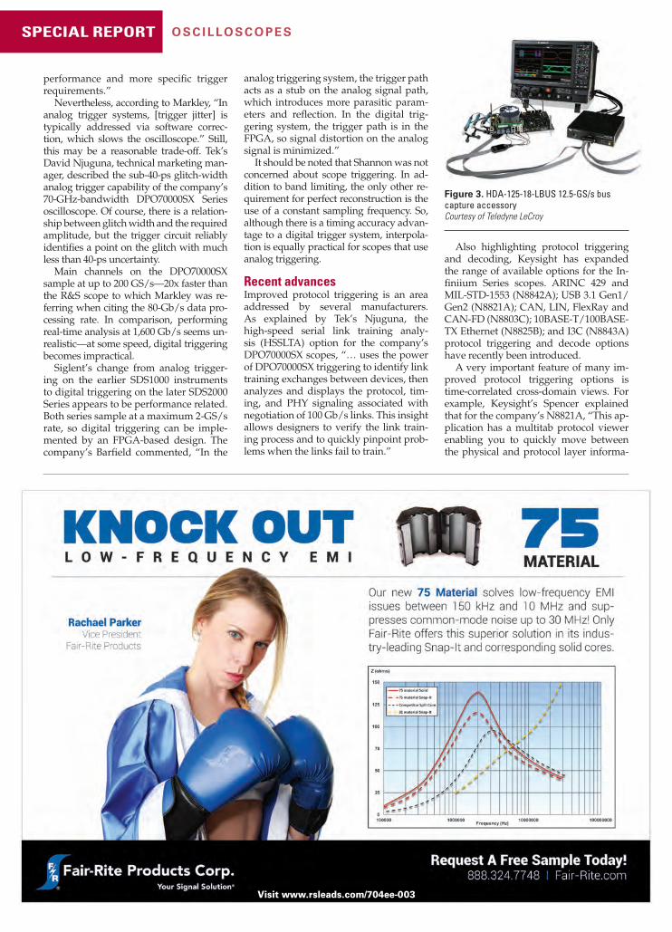
Figure 3. HDA-125-18-LBUS 12.5-GS/s bus capture accessoryCourtesy of Teledyne LeCroy
analog triggering system, the trigger path acts as a stub on the analog signal path, which introduces more parasitic param-eters and refl ection. In the digital trig-gering system, the trigger path is in the FPGA, so signal distortion on the analog signal is minimized.”
It should be noted that Shannon was not concerned about scope triggering. In ad-dition to band limiting, the only other re-quirement for perfect reconstruction is the use of a constant sampling frequency. So, although there is a timing accuracy advan-tage to a digital trigger system, interpola-tion is equally practical for scopes that use analog triggering.
Recent advancesImproved protocol triggering is an area addressed by several manufacturers. As explained by Tek’s Njuguna, the high-speed serial link training analy-sis (HSSLTA) option for the company’s DPO70000SX scopes, “… uses the power of DPO70000SX triggering to identify link training exchanges between devices, then analyzes and displays the protocol, tim-ing, and PHY signaling associated with negotiation of 100 Gb/s links. This insight allows designers to verify the link train-ing process and to quickly pinpoint prob-lems when the links fail to train.”
Also highlighting protocol triggering and decoding, Keysight has expanded the range of available options for the In-fi niium Series scopes. ARINC 429 and MIL-STD-1553 (N8842A); USB 3.1 Gen1/Gen2 (N8821A); CAN, LIN, FlexRay and CAN-FD (N8803C); 10BASE-T/100BASE-TX Ethernet (N8825B); and I3C (N8843A) protocol triggering and decode options have recently been introduced.
A very important feature of many im-proved protocol triggering options is time-correlated cross-domain views. For example, Keysight’s Spencer explained that for the company’s N8821A, “This ap-plication has a multitab protocol viewer enabling you to quickly move between the physical and protocol layer informa-
Visit www.rsleads.com/704ee-003
12-17_EE_201704_SpecRep-Oscilloscopes_FINAL.indd 1612-17_EE_201704_SpecRep-Oscilloscopes_FINAL.indd 16 3/9/2017 2:52:56 PM3/9/2017 2:52:56 PM

evaluationengineering.comApril 2017 17
S PE C I A L R E P O R T - O S C I L LO S C O PE S
tion using a time-correlated timing mark-er.” And, as the company’s website states, “The N8825B 10BASE-T/100BASE-TX Ethernet protocol decoder provides time-correlated views of physical layer (raw data) and transaction layer packets. [The] Unique packet-waveform correlation marker makes it easy to scroll through waveforms to view synchronized packet and symbol lists.”
The R&S RTO2000 features zone triggering in the time and frequency domains—at the same time (Figure 2). The company’s Markley commented that zone triggering was “… especially powerful in the frequency domain as it is sometimes easier to see an issue in the fre-quency domain versus the time domain. A great example is EMI debug where you might be looking for an offending signal at a specifi c frequency. By setting the trigger in the frequency domain, you then get a correlated trigger across all signals (analog, protocol, digital, frequency). In addition, our history mode allows the user to go back in time to see previous trigger events.” He concluded, saying that the zone trigger capability “… works beyond just [the] frequency domain to allow triggering on any math function.”
In a modern implementation of an old idea, Teledyne LeCroy has developed the HDA 125-18-LBUS mixed-signal test solution (Figure 3). Years ago, before in-tegrated MDOs were popular, pattern or state triggering could be added to DSOs by attaching a logic trigger pod to the external trigger input.
The HDA product also is a separate assembly, but as the company’s Busso explained, “Its primary application is acquiring and triggering on up to 18 high-speed parallel digital channels with a sampling rate of 12.5 GS/s. The premier application for HDA 125-18-LBUS is DDR memory. We’ve built specialized DDR command-bus triggers into our DDR De-bug toolkit that enable HDA 125-18-LBUS to trigger on specifi c DDR command-bus requests. Coupled with our QuickLink probing solution that enables seam-less transitions from digital to high-bandwidth analog-signal acquisitions, the HDA 125-18-LBUS mixed-signal test solution makes validation of challenging interfaces such as DDR4 both simpler and more comprehensive….”
Although many products emphasize hardware trigger performance, the fl ex-ibility provided by software triggering can be an advantage. NI’s Robinson men-tioned the NI-TClk software synchroniza-tion tool the company provides, which can “… align the triggering and sampling of instruments of many types to achieve trigger jitter of less than 100 ps across all instruments in a single PXI chassis.”
A recent Pico Technology press re-lease announced the addition of CAN FD decoding to the company’s Pico-Scope 6 software, which “… can already decode a wide variety of serial protocols such as I2C, SPI, and UART, as well as automotive standards such as CAN, LIN, and FlexRay,” said Trevor Smith, business development manager, Test & Measurement. “Now it can also decode CAN FD, which is the latest and fastest version of CAN Bus used in automo-
(GREEN)2AUTOMATED TESTIntroducing PROCYON,the industry’s greenest automated test systems
GREEN Programmable Power Sources Auto-ranging output Full power output over
wide range of test conditions
One supply can replace two or more standard supplies
GREEN Regenerative Electronic Loads
source Eliminates need for noisy cooling fans or
external chiller
Open / Flexible Architecture Supports LXI, IEEE, VXI, PXI and AXI
protocols Compact elements leave plenty of room
for 3rd party equipmentGet the facts and see how PROCYON
14712-A Franklin AvenueTustin, CA 92780714.953.2686
Visit www.rsleads.com/704ee-009
tive and industrial automation applica-tions.”
And, Rigol’s Armstrong noted that the company continues “… to expand the ca-pabilities of existing instruments…. Last year, we added LIN triggering and decod-ing to the 4000 Series. This expands on our automotive-focused triggering that al-ready included CAN and Flexray. LIN trig-ger and decode was immediately added to our free options bundle for all new 4000 Series instruments.” EE
12-17_EE_201704_SpecRep-Oscilloscopes_FINAL.indd 1712-17_EE_201704_SpecRep-Oscilloscopes_FINAL.indd 17 3/9/2017 3:14:28 PM3/9/2017 3:14:28 PM

April 2017evaluationengineering.com18
INSTRUMENTATION
Instruments are proliferating in a variety of formats—includ-ing benchtop and modular—and spanning the time and frequency domains, as versions released thus far this year
demonstrate. Tektronix and Rohde & Schwarz, for example, have respectively introduced a BERT and an oscilloscope while Anritsu has introduced an ultraportable USB millimeter-wave (mmWave) spectrum analyzer. Furthermore, National Instru-ments has upgraded its multiple-instrument VirtualBench with the addition of a model containing a 500-MHz oscilloscope.
PXI, too, has been a focus of innovation, with Astronics Test Systems and SP Devices introducing PXI instruments, Picker-ing Interfaces debuting a PXI multiplexor, and Innovative In-tegration launching a PXIe module with a Xilinx Zynq Z7045 system-on-chip processor. And on the LXI front, Spectrum In-strumentation has added a range of high-speed 14- and 16-bit digitizer products.
Protocol-aware BERTAlthough Tektronix this year has debuted an instrument in the traditional benchtop format, what’s inside is far from tradi-tional. Jim Dunford, product manager for the company’s BERT-Scope product line, called the new Tektronix BSX Series BERT-Scope (Figure 1) the industry’s fi rst 32-Gb/s protocol-aware bit-error-rate test and analysis system. He said the instrument helps characterize the receiver in Gen3 and Gen4 devices and enables users to shorten the time needed to debug link training and bit-error-rate issues.
Dunford explained some of the trends driving the need for an instrument like the new BERTscope. The 5G rollout is driv-ing bandwidth bottlenecks, cloud service providers are bypass-ing OEMs to build their own hardware or are turning to ODMs, and a convergence of datacom and enterprise standards is cre-ating new debug challenges as the same designs incorporate 100/400G Ethernet, PCIe, SAS, and DDR5.
Dunford said that data-link receivers are tested by sending them intentionally impaired data to see how much stress they can handle before misinterpreting incoming data. He added that as 4th-generation serial protocols such as PCIe 4.0 and SAS4 become more complex, it has become increasingly diffi -cult to place a receiver being tested into an appropriate state (such as a loopback state) for testing without protocol hand-shaking between the instrument and the device under test.
That’s where the protocol-aware functions of the BSX Series come into play. The BSX provides the tools and fl exibility need-ed to visualize and control the handshaking and link-training process, understand the protocol, and be able to modify test conditions based on DUT requirements. Dunford said it meets the Rx test challenges of putting the device into loopback mode, performing link equalization, providing autocalibration of stresses, making accurate and repeatable measurements for a large number of test cases, and fi nding root causes of bit-error or link-training problems. In addition, the BSX Series receiver test tool continuously stores the context (timing, bit position) of each bit error. Error-analysis tools such as pattern-sensitivity
Boosting measurement capability from pocket to benchtopBy Rick Nelson, Executive Editor
Figure 1. BSX Series BERTScope 32-Gb/s protocol-aware bit-error-rate test and analysis systemCourtesy of Tektronix
18-23_EE_201704_Instrumentation_MECH_dB.indd 1818-23_EE_201704_Instrumentation_MECH_dB.indd 18 3/9/2017 2:55:53 PM3/9/2017 2:55:53 PM

We stand behind our products with a standard three year warranty.
Visit www.rsleads.com/704ee-006
EE201704-AD_Pickering_50824.indd 19EE201704-AD_Pickering_50824.indd 19 3/7/2017 3:09:11 PM3/7/2017 3:09:11 PM

April 2017evaluationengineering.com20
INSTRUMENTATION
and forward-error-correction emulation use this information to help developers understand the factors contributing to bit errors.
With maximum data rates of 12.5 Gb/s, 24 Gb/s, and 32 Gb/s, the BSX Series is available with tools that automate com-pliance testing, making accurate and repeatable measurements easy to do for the large number of test cases required in the Gen4 standards. With built-in Tx equalization, reference clock multiplication, and interference generation, the BSX Series re-quires fewer cables and is easier to set up and calibrate than previous offerings.
Lab oscilloscopeAlso addressing the benchtop form factor, Rohde & Schwarz has added a new 6-GHz model (Figure 2) to its R&S RTO2000 Series oscilloscopes, opening up measurements on fast commu-nications interfaces and for IoT applications. The characteris-tics of the compact R&S RTO2000 lab oscilloscopes make them suitable for demanding tasks such as power-integrity measure-ments. For such applications, the company also offers the R&S RT-ZPR20 low-noise power-rail probe (see “Ensuring high-quality power for today’s product designs,” page 28).
The new R&S RTO2000’s 6-GHz bandwidth allows develop-ers to test the radio interfaces of 802.11ac WLAN components for IoT modules in the 5-GHz band as well as fast communica-tions interfaces such as USB 3.1 Gen 1 with data rates of 5 Gb/s. Thanks to its multidomain functionality, a single compact in-strument can analyze power supplies, processors, and sensors. Synchronized time, frequency, protocol, and logic-analyses re-sults allow users to debug at the system level.
The company said that up to 16-bit vertical resolution in high-defi nition mode enables developers to detect even the smallest of signal details. Further, the company said, the R&S RTO2000 offers one million waveforms per second, allowing fast identifi cation of even the most sporadic signal faults. The integrated spectrum-analysis and spectrogram display make it possible to observe the signal path in the frequency domain as well as over time.
In addition, a zone trigger lets users isolate events graphi-cally in the time and frequency domain, for example, to sepa-rate read and write messages from memory interfaces. The R&S RTO2000 offers a 2-GS memory, so users can analyze even long pulse and protocol sequences. They also can use the history function to retrieve previously acquired waveforms. The high-resolution, 12.1-inch touchscreen and the color-coded controls make the R&S RTO2000 intuitive to use. The app cockpit pro-vides direct access to all available applications, such as trigger and decoding functions, conformance and signal integrity-tests, I/Q analysis, and even customer-specifi c development tools.
Ultraportable mmWave analyzerAddressing portability, Anritsu introduced the Spectrum Mas-ter MS2760A family, which Russel Lindsay, product marketing manager, Service Infrastructure Solutions Division, described as the fi rst ultraportable, mmWave spectrum analyzers that verify high-frequency designs beyond 50 GHz (Figure 3). Ap-plications, he said, include 5G, E-band building-to-building communications, and V-band satellite-to-satellite and satellite-to aircraft-communications. Still other applications, he said, include electronic warfare and electronic countermeasures. He explained that the instruments leverage Anritsu’s patented NLTL Shockline technology to reduce cost and size while boost-ing performance.
For R&D and test engineers in lab environments, the MS2760A can measure channel power, adjacent channel power, spurious emissions, and occupied bandwidth. The MS2760A allows measurements to be taken directly at the DUT, unlike benchtop models that require expensive cables that can add loss. Lindsay said the instrument is not a replace-all for every other spectrum analyzer but is an affordable alternative for which you don’t pay for features you don’t use. In addition, he said, it can serve as a supplemental instrument that can keep measurements going while a full-featured analyzer is in use elsewhere in the lab.
The Spectrum Master MS2760A compact size is particularly suitable for fi eld testing. The ultraportable instrument fi ts in a technician’s pocket, can be powered by a tablet’s USB port, and offers in a single instrument continuous-sweep capabil-ity, thereby reducing the amount of equipment the technician must carry. But it also can lower the cost-of-test in high-volume manufacturing applications, as it is less expensive than bench-top alternatives. Its ultraportable size also adds fl exibility to production test of larger products, including those in aerospace and satellite applications, Lindsay said.
The Spectrum Master MS2760A has models to support the 32-GHz, 44-GHz, 50-GHz, 70-GHz, and 110-GHz frequencies. A 90-GHz model also is available for countries where an export license is required for analyzers above 90 GHz. It complements Anritsu’s ultraportable analyzer portfolio, which also includes the Power Master MA24507A mmWave power analyzer and Site Master S331P fi eld cable and antenna analyzer.
Multifunction instrumentNI announced in February the VB-8054 instrument (Figure 4), a new higher performance model of VirtualBench. Virtual-Bench, fi rst introduced in June 2014, plays a key role in reduc-ing the cost and footprint of test and measurement systems by consolidating fi ve of the most commonly used instruments into one device without compromising the performance of each instrument.
Figure 3. Spectrum Master MS2760A mmWave spectrum-analyzerCourtesy of Anritsu
Figure 2. 6-GHz R&S RTO2000 Series oscilloscopeCourtesy of Rohde & Schwarz
18-23_EE_201704_Instrumentation_FINAL.indd 2018-23_EE_201704_Instrumentation_FINAL.indd 20 3/9/2017 4:15:45 PM3/9/2017 4:15:45 PM

evaluationengineering.comApril 2017 21
INSTRUMENTATION
Combined with a modern software experience and simple programming interface, VirtualBench creates new effi ciencies for engineers interacting with benchtop test equipment or de-veloping low-cost automated test systems.
“VirtualBench has both an interactive software application as well as APIs for LabVIEW, C, and Python,” said Michael Keane, NI Product marketing engineer for test systems. “This allows the product to uniquely serve engineers who need both light automation and effective, interactive debugging—we have seen this need in both V&V and low-cost production settings. While this need may have been previously served by both automation equipment and traditional benchtop instruments, VirtualBench stands as a single solution for both needs.”
“Engineering workbenches and test systems are getting more and more crowded every day as technologies converge in the latest smart devices,” added Luke Schreier, director of auto-mated test product marketing at NI. “VirtualBench provides the ideal combination of capability at performance levels that can legitimately replace fi ve or more instruments needed to characterize new product designs or validate assembled units on a production fl oor. With 500 MHz of scope bandwidth and a faster generator in the latest model, VirtualBench meets the needs of even more engineers wrestling with how to lower their cost of capital equipment.”
Here are the key new features of the VB-8054: •a four-channel, 500-MHz mixed-signal oscilloscope with 2-GS/s
sampling rate and protocol analysis (34 digital channels); and •a function generator with 40-MHz max sine output plus 5-MHz
output for square, ramp/triangle, DC, and arbitrary modes.Here are some additional capabilities of the VirtualBench
family: • true 5½-digit DMM with 300-V input range, three-channel pro-
grammable DC power supply (up to 3 A), and eight general-pur-pose digital I/O lines;
• intuitive, unifi ed software view of all fi ve instruments, visual-ization on larger displays, and quick functionality to save data and screenshots;
•USB, Ethernet, and Wi-Fi connectivity to Windows software ap-plication and Wi-Fi connectivity to Apple iPad software applica-tion; and
•programming interfaces to automate measurements in Lab-VIEW and C environments.
The VirtualBench application requires zero installation and can load automatically through Windows AutoPlay when con-nected through USB. VirtualBench also includes software ca-pabilities like digital phosphor density maps for displaying multiple acquisitions simultaneously, X-Y mode for plotting channels against one another, and hands-free smart capture for
automatic data capture of repeated stable waveforms. To help better maintain the value of any VirtualBench investment, NI provides free software and fi rmware updates as new features are released. These features, in addition to the consolidated in-terface, help engineers streamline their approach for benchtop characterization and validation. The small footprint and low price of VirtualBench compared with its equivalent set of boxes help enable lower cost of test on a manufacturing fl oor.
The VirtualBench hardware family consists of three models most easily designated by oscilloscope analog bandwidth: 100, 350, and 500 MHz. Through these models, the VirtualBench
Figure 5. PXIe-1802 arbitrary waveform generator and PXIe-1803 digitizerCourtesy of Astronics Test Systems
Figure 4. VB-8054 VirtualBench with 500-MHz oscilloscopeCourtesy of National Instruments
family serves a range of applications and price points in aca-demic labs, hardware characterization/debug benches, and automated test systems.
“From the beginning,” said Keane, “the VirtualBench prod-uct line was intended to be a family of options, and the new 500-MHz model completes this entry-level family that also in-cludes 100- and 350-MHz models that serve a variety of ap-plication needs.”
PXI instrumentsAstronics Test Systems has begun 2017 by introducing two new test instruments: the new PXIe-1802 arbitrary waveform gen-
18-23_EE_201704_Instrumentation_FINAL.indd 2118-23_EE_201704_Instrumentation_FINAL.indd 21 3/9/2017 3:15:00 PM3/9/2017 3:15:00 PM

April 2017evaluationengineering.com22
INSTRUMENTATION
erator and the new PXIe-1803 digitizer (Figure 5), which serve aerospace, de-fense, communications, and other high-reliability applications.
“The demand for high-performance PXI test instruments continues to rise both as legacy test systems are upgrad-ed with additional functionality and as new systems are introduced,” explained Steve Fairbanks, senior director of prod-uct marketing for Astronics Test Systems, in a press release. “Our latest additions to our product portfolio enhance our capability to provide a breadth of test functionality for next generation test initiatives.”
The PXIe-1802 arbitrary waveform generator (AWG) offers both speed and performance for output frequencies of up to 125 MHz. With built-in wave-forms, high signal quality, high density and modularity, and other features, this AWG delivers dual 14-/16-bit waveform generator channels, bandwidths of 90 to 140 MHz, synchronization, and 250-μV measurement accuracy.
The PXIe-1803 is a 130/180-MS/s du-al-channel digitizer that supports input frequencies up to 175 MHz, the company said. The new dual-channel 14-/16-bit digitizer is confi gurable with separate or fully synchronized channels. Other features include waveform bandwidths of 65 to 175 MHz (typical), 64M of wave-form memory per channel, and relative accuracy of up to 0.006%.
Pickering Interfaces also has begun 2017 with new PXI products—the 40-614
Figure 7. DN6.44X digitizerNETBOX LXI digitizerCourtesy of Spectrum Instrumentation
family of high-density 2-A PXI multiplex-ers (Figure 6), available in 20 different confi gurations and designed for signal routing in ATE and data-acquisition sys-tems. The multiplexers use high-quality electromechanical signal relays, allowing each channel to switch voltages up to 200 VDC/140 VAC at the 2-A current rating.
“These multiplexers offer a low-cost fi xed-confi guration alternative to ver-satile solutions, making them simpler to program, and it also improves isola-tion between banks,” commented Shaun Fuller, Pickering’s switching product manager, in a press release.
The PXI multiplexers may be operated as conventional multiplexers with break-before-make action when a new channel is selected. In addition, multiple chan-nels may be simultaneously selected on the two-, four-, eight-, 16-, and 32-pole versions. Large multiplexers may be con-structed by daisy-chaining the common signals from multiple PXI modules.
The product range also is supported by several Pickering software and hard-ware tools, including the eBIRST switch-ing system test tools, which provide a quick and simple way of fi nding relay failures within modules; and Switch Path Manager, which simplifi es signal routing through complex switching systems.
From-factor, connectivity optionsAddressing a variety of form-factor and connectivity options, SP Devices, an e2v company, has launched the ADQ7, which it calls the fi rst digitizer to combine 14-bit vertical resolution with a sampling rate of up to 10 GS/s.
Following on the company’s ADQ14 digitizer, the ADQ7 provides a higher sampling rate, larger FPGA, increased memory and data transfer rate, and a higher bandwidth analog front end. The ADQ7’s combination of high band-width and high dynamic range makes it suitable for applications such as those involving LiDAR, radar, mass spectrom-etry, radio-frequency sampling and re-cording, and automated test.
The ADQ7 hosts a Xilinx Ultrascale XCKU060 FPGA, which can be accessed through a fi rmware develop-ment kit. In addition, to help shorten design time, a number of option-al standalone fi rmware packages contain appli-cation-specifi c, real-time signal-processing func-tions. These fl exible fi rm-ware solutions make the ADQ7 suitable for OEM integration.
Jan-Erik Eklund, digitizer product manager at SP Devices, commented in a press release, “It is very exciting that we can offer the market a 14-bit resolution digitizer that maintains such a high sam-pling rate. This new digitizer’s unique performance shows our commitment to innovation and maintaining our position as the world leader in high-performance data acquisition.”
The ADQ7 will be available in form factors and connectivity options includ-ing MicroTCA (MTCA.4), USB 3.0, PCIe, PXIe, and 10 GbE, and it supports sus-tained data-transfer rates of up to 5 GB/s (with PCIe). A software development kit is included free and supports multiple languages including C++, C#, Matlab, Python, and LabVIEW. The board can be operated under both Windows and Linux.
LXI digitizersAlso addressing the high-resolution digi-tizer market is Spectrum Instrumentation, which has added a range of high-speed 14- and 16-bit digitizer products, desig-nated DN6.44X, to its digitizerNETBOX family (Figure 7) for applications where multiple electronic signals need to be ac-quired and analyzed. The company said its new instruments feature up to 24 fully synchronized channels. The 16-bit ADC models offer sampling rates of either 130 MS/s or 250 MS/s, while the 14-bit units feature sampling rates of 500 MS/s.
The high sampling rates and resolu-tions make the DN6.44x Series suitable for wide-band signal capture. The high chan-nel density supports applications where arrays of receivers, sensors, detectors, rectifi ers, antennas, and other electronic devices are to be used and tested.
To ensure all models deliver suitable cross-channel timing capability with minimal phase error, the ADCs on each channel are clocked synchronously. Each channel also is equipped with its own front-end amplifi er that features six input ranges (from ±200 mV up to ±10 V full scale), switchable input impedance (50 Ω and 1 MΩ), and programmable positive
Figure 6. High-density 2-A PXI multiplexer with electromechanical relaysCourtesy of Pickering Interfaces
18-23_EE_201704_Instrumentation_MECH_dB.indd 2218-23_EE_201704_Instrumentation_MECH_dB.indd 22 3/9/2017 2:56:18 PM3/9/2017 2:56:18 PM

evaluationengineering.comApril 2017 23
INSTRUMENTATION
HypotULTRA®
Electrical Safety Testing Powerhouse
Now with Ground Bond
13860 W. Laurel Drive, Lake Forest, IL 60045 USA call +1-847-367-4077 online arisafety.com
y g
Discover more at go.arisafety.com/ultra-gb
AC Hipot DC Hipot Ground Bond
Insulation Resistance
Visit www.rsleads.com/704ee-002
input offset for unipolar signals. The ana-log bandwidth is as high as 250 MHz (for 500-MS/s models).
Each DN6.44x instrument is equipped with a large onboard acquisition memory of 512 MS/channel and trigger circuitry to allow the capture of a range of input signals. Each channel as well as two external inputs can act as a trigger source with the capability of combining all sources by AND/OR logic function. Different acquisition modes, which include single-shot (transient recording), streaming (FIFO), segmented (multiple recording), gated (gated sampling), or a combination of segmented and slow chart-recorder operation (ABA mode), can be combined with internal-trigger time stamping.
The units feature an industrial chassis with integrated cooling, a replaceable dust fi lter, and low-noise power supplies. Front-panel SMA connectors are used for the channel inputs, external clock, and external triggering, while LED lights provide a visual indication for the power, trigger, and LAN status. Based on the LXI instrumentation standard (following the LXI Device Specifi cation 2011 rev. 1.4), the digitizerNETBOX products also are designed for automated testing and remote applications. Full remote control is achieved through a simple gigabit Ethernet port, which allows connection to any PC or LAN.
CPUs plus FPGA fabricFinally, an instrument system might need some processing power. To that end, In-novative Integration, a Molex company, has announced the COPious-PXIe. The 8HP PXIe-compatible plug-in card em-ploys the Xilinx Zynq Z7045 system-on-chip processor, which provides dual fl oating-point ARM A9 CPUs and a large user-programmable FPGA fabric.
COPious-PXIe incorporates a high-pin-count VITA 57.1-compliant FMC module site, compatible with Innovative’s range of FMC modules and tools. The onboard FPGA fabric directly controls FMC pe-ripherals, enabling deep integration of sophisticated, user-customized DSP algo-rithms. The module serves software-de-fi ned-radio, radar, LiDAR, optical-control, and other demanding applications, which it can effi ciently address even in conjunc-tion with conventional PXIe system con-trollers running non-real-time operating systems such as Windows or Linux.
“This powerful single-board comput-er/adapter adds a rich portfolio of cut-ting-edge DAQ FMC modules and tools into the PXIe ecosystem,” said Jim Hen-derson, president of Innovative Integra-tion, in a press release. Customers can
implement custom control, communica-tions, and analytical algorithms within the Zynq’s copious on-chip FPGA fabric to perform real-time signal processing of signals with up to 500 MHz of instan-taneous bandwidth.”
The product can be tailored to a vari-ety of markets including embedded and mobile instrumentation, remote and autonomous I/O, and distributed data acquisition. EE
Coming next monthA look at the past, present,
and future of PXI as the
standard nears the
two-decade mark.
18-23_EE_201704_Instrumentation_FINAL.indd 2318-23_EE_201704_Instrumentation_FINAL.indd 23 3/9/2017 3:15:11 PM3/9/2017 3:15:11 PM

April 2017evaluationengineering.com24
ASSET MANAGEMENT
Asset management software (AMS) is a good example of a term that may appear to be self-explanatory but actually means different things depending on the type of orga-
nization and the department that is using it. There’s always a database of some kind that records information about assets. But, AMS products differ widely in the level of additional capabilities they provide.
Many small companies initially use a homemade spreadsheet to manage assets, and that’s a simple solution if only a small number of items are involved and their mix doesn’t frequently change. On the other hand, as a company grows, a spreadsheet’s inherent limitations soon are recognized.
Rather than directly working with serial numbers and text descriptions, AMS products often rely on a special identifi ca-tion tag attached to a physical asset. This can be as simple as a one-dimensional barcode that can be scanned with special wire-less scanners or smartphones and the information automatically used to update a central database.
A common extension of this idea is to use a label with a two-dimensional quick-response (QR) barcode, which can convey much more information. Depending on the pattern’s resolution, as many as a few thousand characters can be encoded. Typical commercial applications embed a relevant URL so that scanning with a smartphone immediately provides the user with more details. For example, a QR code on a food product could link to a website with nutritional information and claims about the product’s benefi ts.
For an AMS application, asset-related information that does not change—such as purchase date, product description, and the company name—could be encoded along with the identifi cation number. Figure 1 identifi es some of the standard required areas in a typical QR pattern.
Moving on from relatively simple isolated solutions and conforming to the ISO 55000 Asset Management System Stand-ards means that an organization has adopted a transparent and well-documented approach to asset management. As an SAP white paper1 explains, “It’s important to note that meeting the ISO 55000 stand ards requires more than just a standalone asset management application. The scope of the standard is enterprise wide, so other asset categories, such as fi nancial assets, human assets, information assets, and intangible assets, must be inte-grated with the activities and practices being used to manage physical assets.”
For SAP and rival software company Oracle, an AMS prod-uct may be a highly optimized module intended for use with other modules in a comprehensive enterprise resource planning
(ERP) or enterprise resource management (ERM) software suite that covers all aspects of an organization’s activities.
Assets, assets, assetsPhysicalThe GoCodes Asset Manage-ment cloud-based system re-lies on affi xing a QR label to each piece of equipment. The clever part is using a smart-phone to scan the label. Not only does this allow you to log into the central database from anywhere, but also the tagged item gets associated
with the phone’s GPS location each time the label is scanned.According to a recent PC MAG.com review,2 “GoCodes stick-
ers provide the current location of the asset, plus the app has the fl exibility to specify details about each asset, including custom information on the sticker itself and custom fi elds on your screen. Another advantage of a physical solution is the possibility that a lost asset will be returned by a Good Samaritan. In addition to scanning the QR code, the GoCodes website offers anyone who fi nds a tracked asset with the ability to directly enter the number, without requiring any app downloads.”
AMS systems can be adapted to maintain many kinds of infor-mation relevant to a physical asset. For example, the California Code of Regulations3 specifi es the responsibilities of automated external defi brillator (AED) providers. In part, the regulations re-quire that “… the defi brillator is maintained and regularly tested according to the operation and maintenance guidelines set forth by the manufacturer and according to any applicable rules and regulations set forth by the governmental authority under the federal Food and Drug Administration and any other applicable state and federal authority.”
The regulations also mandate that, “The defi brillator is checked for readiness after each use and at least once every 30 days if the AED has not been used in the previous 30 days. Re-cords of these periodic checks shall be maintained.” This regu-latory requirement is similar to any scheduled maintenance as-sociated with an asset and can be handled by an AMS system. A report generated by the AMS can prove compliance by listing successive test results and their dates.
AssetCloud is an AMS available from Wasp Barcode Tech-nologies that, according to the company’s website, “… currently manages equipment across hundreds of different industries in-cluding construction, manufacturing, law enforcement, fi re de-partments, energy restoration, and the United States military. As-setCloud uses barcode scanning capabilities, which allow your organization to track equipment system wide.” While barcodes are used to identify assets, a sign-in, sign-out scheme accounts for asset relocation. Instead of GPS information, locations such as “storeroom 1” are entered into the database.
In addition to keeping track of asset details, this AMS ad-dresses the broader requirements of medium to large enterprises, such as managing contracts, service agreements, and software li-censes. The program also has fi ve customizable methods of asset depreciation.
Microlease’s LEO Asset Management Solution (Figure 2) includes aspects common to other physical asset management systems and some unique capabilities. Because the company both sells and leases test equipment, in addition to helping to manage assets, the Microlease AMS also serves as a marketing tool. As the company’s website comments, “This allows us to accurately analyze your situation, identify areas for improve-ment, and propose a world-class test management process re-design.” Of course, you can ignore the recommendations and simply use the system for asset location tracking and deprecia-tion management.
The website further explains that LEO utilizes the Oracle da-tabase and, similar to other AMS applications that are intended for use by larger organizations, “… is compatible with all other major ERP fi nancial systems including SAP and Oracle Finan-cials. LEO’s database server runs on a wide range of hardware platforms and can be hosted either internally or in the cloud.”
And, because of its test-related features, LEO also can help an organization to more accurately calculate the cost of test. The Test Management section assists with “… scheduling and
Keeping track of what you’ve gotBy Tom Lecklider, Senior Technical Editor
Figure 1. QR pattern with required standard areasCourtesy of Thonky
24-25_EE_201704_Software_MECH_dB.indd 2424-25_EE_201704_Software_MECH_dB.indd 24 3/9/2017 12:05:18 PM3/9/2017 12:05:18 PM

evaluationengineering.comApril 2017 25
ASSET MANAGEMENT
managing specifi c test projects by as-signing assets and engineers.” And, the Investment Dash-board helps you to “… monitor key per-formance indicators of your business to make informed deci-sions.”
In contrast, MAT-solutions, an accred-ited calibration lab, takes a standalone approach to working closely with compa-
nies that want to outsource test equipment asset management. As the company’s website proposes, “From our Dataview Browser online management tool to completely outsourced cal-ibration and asset management programs, MAT tailors fl exible custom support solutions….”
The Sage Fixed Assets program also has physical asset track-ing capabilities but emphasizes the fi nancial side with 300,000 GAAP and IRS rules for depreciation and several tax forms for direct submission. The Sage website states, “An accurate inven-tory is essential to your organization’s internal control of fi xed as-sets, helping to prevent theft, realize loss or damages, and ensure accurate insurance coverage and costs. An inventory helps you eliminate accounting inaccuracies due to ‘ghost assets’—fi xed as-sets that are on your books but no longer at your company.”
This application uses barcode labels to identify equipment and can conduct inventories concurrently at multiple locations with reconciliation in a central database. In addition to text strings representing serial numbers, locations, and activity history, the program stores photos and related documents such as invoices.
SoftwareFor an organization’s IT department, components of the physi-cal plant such as routers, switches, and computers are included in an AMS system, but so too are licensed software applica-tions. As a recent white paper4 discusses, the installed software and its use patterns can be remotely determined if your ASM system has the right mix of agentless scanning software to deal with most of the connected assets as well as installed agents to monitor computers.
The paper notes, “Knowing what you’re working with tells you what patches you need to deploy, what software licenses you need to own, what warranty coverage you’re entitled to, and what repairs you need to be prepared to make.” Proving compliance—in this case, showing that your organization holds current licenses for all installed software—is an important ben-efi t of an automated system.
Dell, the company promoting the fi ve steps discussed in Reference 4, recommends the KACE K1000 Systems Manage-ment Appliance, which is a specially confi gured computer that “… captures detailed confi guration information for desktops, notebooks, servers, printers, and networking equipment such as routers and switches.” The K1000 is available as a physical computer system or as a cloud-based service.
Looked at more broadly, AMS systems are management tools that gather and present information to assist decision making. Examples given in Reference 4 include the opportunity to re-duce license costs by knowing how many people actually use a given application and choosing how an application is provided if only one application among several in a licensed software suite is being used.
Pulseway from MMSoft Design is an IT-oriented AMS sys-tem described in a recent PC MAG.com review as a “… pow-
erful and easy-to-use mobile client.” You need to install agent software on your computers to provide full remote control and data collection. And, you must confi gure SNMP management information base variables before SNMP devices can be discov-ered and monitored. However, as the article notes, once the ini-tial setup is complete, operation is straightforward in large part due to the good user interface.
Asset management redefi nedFluke manufactures a wide range of handheld electronic test equipment including multimeters, oscilloscopes, and thermal imaging cameras. Largely intended for the plant maintenance market, many of these “test tools” have a wireless capability via the company’s Connect software suite. In addition to the basic Connect Measurements module, you also can focus on the per-formance of particular assets through the Asset and Condition Monitoring applications.
Although the Fluke Connect website mentions asset manage-ment, in this case the “asset” is production equipment of some type. For example, you could be concerned about the status of motor number 47 that drives a critical pump. Using electrical and thermal tools, you can collect measurements over time so that any performance deterioration can be determined. Those measurements are directly saved into a cloud database via the Measurements app. Using the Assets module allows you to group only the measurements associated with motor 47 so that trends can be more easily found. And, with Condition Monitor-ing software, you can set alarms to continuously identify opera-tional anomalies.
No doubt, the Connect software is very useful, but it’s better described as being in the condition monitoring category than as asset management. On the other hand, to plant maintenance engineers, the asset management phrase may imply production equipment performance and its optimization. According to in-formation on the company’s website, Fluke Connect with the Asset module “… is the only system that saves measurements directly from your test tool into a work order.”
Correct sizingThere is no shortage of AMS systems from which to choose one that’s right for your company. An initial way to narrow the choice is to determine whether the software can be standalone or if it must integrate with a larger ERP or ERM application. Does your organization need to comply with the ISO 55000 standard?
Of course, you also must determine what types of assets you are going to manage—are they only physical assets, and if so, are they used at several locations? Alternatively, do you need to comply with software licensing requirements and perhaps also monitor software usage and performance?
And, when selecting an asset management application, does your company have the necessary IT skills to correctly con-fi gure and use the software? Finally, do you have the budget to afford the AMS system you have decided to buy? From the descriptions given on the various manufacturers’ websites, at least the budget question should be easy to answer: Compre-hensive asset management is a necessary part of operating a business, even a small one. EE
References1. Enable Asset Management Systems with Integrated Enterprise Information Solu-tions Using Technology to Support ISO 55000 Standards for Asset Management, SAP, White Paper, November 2014.2. “GoCodes,” PC MAG.com, October 2015.3. “California Code of Regulations, Title 22, Social Security, Division 9, Prehospital Emergency Medical Services, Chapter 1.8, Lay Rescuer Automated External Defi brilla-tor Regulations, Article 4. Operational AED Service Provider and Vendor Requirement, Section 100041. AED Service Provider Operational Requirements, parts 6 and 7,” 2009. 4. “Five Steps for Easier—and More Effective—IT Inventorying,” Dell Software, De-cember 2013.
Figure 2. Microlease LEO featuresCourtesy of Microlease
24-25_EE_201704_Software_FINAL.indd 2524-25_EE_201704_Software_FINAL.indd 25 3/9/2017 3:15:32 PM3/9/2017 3:15:32 PM

April 2017evaluationengineering.com26
COMPONENTS
The Intuitive Internet of Things, or I2oT, is a concept imec has been working to bring to fruition. Speaking at the imec Technical forum held in conjunction with SEMICON West
2015, Luc Van den hove, imec’s president and CEO, described the concept, choosing wearable technology as an example. To be successful, he said, wearables will have to fade into the back-ground of your life and employ smart, personalized algorithms that take into account context, intention, and emotional state—hence the term “intuitive.”
The 2017 International Solid-State Circuits Conference, held in February in San Francisco, offered imec the opportunity to fur-ther elaborate on the I2oT, which relies on tiny sensor nodes in-visibly embedded in the environment and wirelessly connected to the Internet. A bulky battery would prevent such a node from fading invisibly into the background. Further, as billions of IoT devices are deployed, battery replacement could become impos-sible. Therefore, imec has been working to cut power consump-tion, especially as related to wireless connectivity.
“We are pleased with our collaboration with ROHM to solve yet another challenge and deliver an ADPLL that adds to imec’s record low-power-radio design portfolio,” said Kathleen Philips, program director at imec/Holst Centre for Perceptive Systems for an intuitive IoT. “With this performance, this all-digital PLL has become a mature and superior alternative to the widespread analog PLLs. The ADPLL is ready for industrial mass production and currently is being transferred to our industrial partners for product integration.”
When asked about prospects for scaling, she said, “The road-map toward 22 nm is very promising: The relative benefi ts of the ADPLL become more and more signifi cant as you go down in technology node.” At 22 nm, she said, “Power-consumption and silicon-area benefi ts, as compared with analog PLLs, become even more pronounced than the improvements that we have al-ready realized in 40 nm.”
She continued, “Maybe even more important, porting to small nodes and other fabs will be faster as compared to the redesign needed for a classical analog PLL. In past years, we have created a lot of scripting for design, verifi cation, and lab analysis of the ADPLL such that we are able to transfer a signifi cant verifi ca-tion package to our customers. This really helps to reduce design and verifi cation time of ADPLLs. This aspect has been a point of concern for productizing ADPLLs in the past but is now well ad-dressed. The road to smaller nodes is wide open.”
“We are proud that we have developed the low-power ADPLL with imec,” commented Isao Matsumoto, director, LSI Produc-tion Headquarters/LSI Product Development Headquarters at ROHM, in a press release. The plan is to develop an RF trans-ceiver with the ADPLL and integrate ROHM’s ultra-low power sensors and micro controllers into a “sensor edge” module. “We hope they will be leaders of the IoT market,” he concluded. EE
Reference
1. Nelson, R., “Technologists tout IoT success,” EE-Evaluation Engineer-ing, September 2015, p. 6.
All-digital phase-locked loop offers sub-mW power consumptionBy Rick Nelson, Executive Editor
Figure 2. All-digital PLL with low power consumption (0.67 mW) and all spurs less than -56 dBcCourtesy of imec
Figure 1. Sub-mW all-digital PLL presented at ISSCCCourtesy of imec
In the latest power-reduction effort described at ISSCC, imec, Holst Centre, and ROHM teamed up to present an all-digital phase-locked loop (ADPLL) for IoT radio transceivers (Figure 1).
The PLL traditionally has been an analog component—a ma-jor power consumer that can take up 30% of a radio area. Con-sequently, the research community has been working on digital alternatives. All-digital PLLs enable a smaller footprint, better control and testability, and improved scaling to advanced CMOS nodes. However, to date, they have lagged behind in terms of performance compared to analog solutions.
That’s the problem imec, Holst Centre, and ROHM teamed up to solve. Their new ADPLL features a small area (0.18 mm² in 40-nm CMOS) and low power consumption (0.67 mW) while limiting all spurs lower than -56 dBc and keeping jitter below 2 ps (Figure 2).
The new all-digital PLL supports all specifi cations of Blue-tooth low energy radios while reducing cost and power con-sumption below any of today’s solutions. To achieve its level of performance, the dividerless fractional-N digital PLL features a power-effi cient spur-mitigation technique and a digital phase unwrap technique.
26_EE_201704_Components_MECH_GH.indd 2626_EE_201704_Components_MECH_GH.indd 26 3/9/2017 10:34:34 AM3/9/2017 10:34:34 AM

EE201704-AD_HOUSE.indd 27EE201704-AD_HOUSE.indd 27 3/8/2017 11:00:33 AM3/8/2017 11:00:33 AM

April 2017evaluationengineering.com28
EMC PRODUCT FOCUS
Ensuring high-quality power for today’s product designsBy Rick Nelson, Executive Editor
Power can present problems in modern product designs. Rohde & Schwarz notes that the quality of the power supply is a key factor in the functionality and performance of sensitive electronic circuits—including IoT
components with fast digital interfaces, fast memory chips, and sensitive analog circuits—where disturbance signals on the DC power-supply network can lead to EMC problems or impair circuit functionality. To help isolate such problems, the company at DesignCon in Santa Clara in January introduced a power-rail probe that works in conjunction with its oscilloscopes.
Of course, starting with a power supply designed for EMC can help. During MD&M West 2017 in February in Anaheim, SL Power showcased high-performance power supplies for medical applications that meet 4th Edition EMC and DOE Level VI effi ciency standards. Other products highlighted here include capacitors, chokes, gaskets, and cases.
EMI-suppression capacitorsMKP X2 capacitors serve EMI
suppression applications. Com-
pared with conventional X2
capacitors designed for rated
voltages of 305 VAC, these new
components offer a higher rat-
ed voltage of 350 VAC, making
them suitable for EMI suppres-
sion in input fi lters (specifi cally
for applications on the North
American market) and output
fi lters of photovoltaic inverters, for example.
The capacitance range extends from 0.47 μF to 10 μF. Even
under severe ambient conditions, the new capacitors are char-
acterized by a stable capacitance, as verifi ed in damp heat
tests, in which the change in capacitance does not exceed 7.5%
(test conditions: 1,000 hours at 85°C with a relative humidity of
85% and a voltage of 330 VAC). The maximum operating tem-
perature of the components is 110°C.
The X2 capacitors are approved in accordance with UL and
EN and, depending on the capacitance, are available with a lead
spacing of 27.5 mm or 37.5 mm. Both the casing and the epoxy
resin sealing material comply with the UL 94 V-0 stand ard. The
capacitors are suitable for applications with higher demands
in terms of current capability as well as capacitive power sup-
plies. EPCOS AG, www.rsleads.com/704ee-177
Power-rail probeThe R&S RT-ZPR20 low-
noise power-rail probe offers a
bandwidth of 2 GHz and works
in combination with the R&S
RTE and R&S RTO2000 oscil-
loscopes. With its low inherent
noise and an attenuation factor
of 1:1, the R&S RT-ZPR20 probe
enables users to measure and analyze in detail even small dis-
turbance voltages using the many functions offered by the os-
cilloscopes, such as spectral analysis. Thanks to the dynamic
range of ±850 mV and large DC voltage offset range of ±60 V,
the probe permits analysis of the smallest disturbance signals
during power-integrity measurements, even on DC power sup-
plies with a high voltage level.
The R&S RT-ZPR20 also features an integrated high-preci-
sion DC voltmeter that allows users to simultaneously mea-
sure a power supply’s DC component, irrespective of the offset
voltage. This reading and the signal voltage are transmitted
to the oscilloscope and displayed, enabling the DC level and
ripple to be measured in parallel when qualifying power sup-
plies for highly sensitive electronic components such as CPUs
and FPGAs. Users see at a glance whether the ripple volt-
ages lie within the often very tight power supply tolerances.
Rohde & Schwarz, www.rsleads.com/704ee-178
Medical power suppliesThe ME Series AC/DC external power supplies are specifi -
cally designed to meet challenging home healthcare power
requirements for patient-monitoring equipment and respira-
tory devices that demand a high level EMC, EMI mitigation,
and AC input performance. Available in 10, 20, 30, 40 and 60
W, the ME models are fully compliant with Level VI effi ciency
requirements per U.S. Department of Energy and compliant to
IEC 60601-1-2, 4th Edition, for EMC.
In addition, the MB65 Series offers compact 65-W convec-
tion-cooled AC/DC internal power supplies that meet power
demands for next-generation medical applications including
patient-monitoring, surgical, imaging, home healthcare, and
laboratory equipment. Measuring 2 x 3.5 x 1.3 inches, the sin-
gle-output MB65 models with 2MOPP isolation deliver a high
level of EMC, EMI, and AC input performance that medical de-
vices require. SL Power, www.rsleads.com/704ee-179
Power-line chokesThe WE-TPB HV series of current-
compensated, three-phase, power-line
chokes serves high-voltage applica-
tions. This new series guarantees a
rated voltage up to 760 VAC, which
the vendor reports is 70% more than
that offered by comparable products.
It was made possible by a patented
design using a novel plastic casing,
separating strip, and grid plate.
The chokes’ toroids can be made both of MnZn ferrite mate-
rial as well as of nanocrystalline material—making it possible
28-29_EE_201704_ProductFocus_MECH_dB.indd 2828-29_EE_201704_ProductFocus_MECH_dB.indd 28 3/9/2017 12:02:41 PM3/9/2017 12:02:41 PM

evaluationengineering.comApril 2017 29
EMC PRODUCT FOCUS
to achieve high insertion losses even in broadband applica-
tions. All insulation materials used in these products are UL 94
V-0 listed. As a measure to enhance the stability on a PCB, the
chokes also can be fi xed in place with a tapping screw. Typi-
cal applications for this series include frequency inverters and
high-performance charging stations. Würth Elektronik eiSos, www.rsleads.com/704ee-183
COTS power supplyThe DCR2U-2000D
critical-mission COTS
power supply meets
the need for reliable
DC output from three-
phase AC aircraft power over a wide frequency range. The DC-
R2U Series of COTS power supplies accept inputs of 200 to
375 VDC or 115/200 VAC, three-phase, at 360 to 440 Hz. Custom
inputs also are available upon request.
Output power of 2,000/3,000/4,000 W is available from the
DCR2U Series, with voltages from 3.3 VDC to 48 VDC. The new
2,400-W DCR2U-2000D power supply is designed to provide
+28 VDC at 71 A (2,000 W) and +12 VDC at 33.3 A (400 W). Like
other DCR2U power supplies, this unit also has protective cir-
cuits, controls, and indicators and wide-ranging operating and
storage temperatures. It is designed to meet MIL-STD-810F for
shock and vibration and MIL-STD-461E for EMI/EMC.
DCR2U Critical Mission COTS power supplies can be mount-
ed in 19-inch racks and need only 2U (3.50-inch) space. Weight is
28.9 lb. Behlman Electronics, www.rsleads.com/704ee-176
EMC caseThe 3U RackCase
PRO is available in
stand ard depths of 9.45,
13.78, and 18.11 inches
(240, 350, and 460 mm),
with custom depths
available to special or-
der. To reduce confi gu-
ration time and cost, it
eliminates the need for
drilling when installing
chassis trays, brack-
ets, and electro-mechanical components. The design provides
all-around access during assembly with top and base covers
that slide into place once the unit has been populated with the
housed electronics and other components. RackCase PRO has
been designed for applications such as audio, broadcast, in-
strumentation, and other areas where EMC integrity could be
an issue; the design ensures conductivity between all com-
ponent parts of the assembly, providing EMC capability as
stand ard.
The heavy-duty extruded side panels form a rigid structure
in conjunction with the front and rear panels and top and base
covers. The external face of the side panels features full-length
slots for fi tting telescopic slides that enable the unit to be with-
drawn from a 19-inch rack for easy access. Internally, the side
panels have 12 separate channels into which tapped strips or
individual M4 captive nuts can be positioned to provide secure
mounting points for the housed components. The conductive
fi nish ventilated or plain steel covers slide into dedicated slots;
conductive gaskets in these slots prevent movement and en-
sure conductivity between all components of the assembly. The
hole pattern in the ventilated covers provides effi cient convec-
tion or forced cooling without compromising the EMC integrity.
Verotec, www.rsleads.com/704ee-182
Finger stock gasketsEMI-shielding BeCu fi nger stock
gaskets are offered in more than
100 standard profi les. Download-
able interactive drawings allow
the user to modify the strips to
their exact requirements. Berylli-
um copper’s mechanical and elec-
trical properties make it a suitable
material for EMI/RFI shielding,
with greater than 100-dB attenua-
tion. BeCu offers maximum spring
properties for strength and fatigue resistance as well as long
life without compression set.
Mounting options include snap-on, stick-on, clip-on, track,
extrusion, welding, and soldering. A variety of in-house plat-
ing options keeps lead times short. In addition, quick delivery
programs are in place for both clean-and-bright and tin-plated
standard and confi gured products to support customers’ ur-
gent requirements. An optional DiamondBack textured surface
for high-frequency applications is available. Standard gaskets
also can be modifi ed, minimizing the cost of producing custom
gaskets. Tech-Etch, www.rsleads.com/704ee-181
External power suppliesThe medical- and ITE-certifi ed
DTM300-D external power sup-
plies offer a choice of class I or
class II (no ground connection) in-
puts and meet Level VI DoE stan-
dards for effi ciency and off-load
power. The DTM300-D is certifi ed
to both the medical IEC 60601-1
and ITE IEC 60950-1 stand ards,
making it suitable for a variety of power-hungry medical, in-
dustrial, and test and measurement applications.
The convection-cooled DTM300-D is housed in a rugged,
vent-free enclosure, measuring 222 mm x 112 mm x 45 mm.
AC is applied using the standard IEC 60320-C14 (three-prong)
or 60320-C18 (two-prong) connector and DC provided through
a 10-pin Molex Mini-Fit connector. Other connectors are avail-
able upon request. The adapters also feature over-voltage and
over-current protection.
Accepting a 90- to 264-VAC input, the 300-W adapters are
available with 12-V, 19-V, 24-V, 28-V, 48-V, and 54-V outputs and
can operate in ambient temperatures ranging from -30°C to
+60°C (derating linearly to 50% load from 40°C to 60°C). In ad-
dition to satisfying DoE Level VI requirements with an average
effi ciency of greater than 88%, the power supplies have an off-
load power draw of less than 0.5 W.
The DTM300 has been certifi ed to IEC/ES/CSA/EN 60601-1
and IEC/UL/CSA/EN 60950-1, and it carries the CE mark for
low-voltage, EMC, and RoHS2 directives. All models meet EN
60601-2, IEC 60601-1-2 Ed4:2014, EN 55011/EN 55022 Class B,
EN 55024 Class B, FCC Part 15 Class B, and FCC Part 18 Class
B emissions and immunity standards. Input to output isolation
is 4,000 VAC (2 x MoPP), with a touch current of <100 μA. Class
I models are suitable for BF rated equipment with an output
to ground isolation of 1,500 VAC. TDK-Lambda Americas, www.rsleads.com/704ee-180
28-29_EE_201704_ProductFocus_FINAL.indd 2928-29_EE_201704_ProductFocus_FINAL.indd 29 3/9/2017 3:16:03 PM3/9/2017 3:16:03 PM

April 2017evaluationengineering.com30
EE PRODUCT PICKS
Open-top BGA socketThe SG-BGA-6457 socket for
1-mm pitch, 121-pin BGA ICs is
designed for 12 x 12-mm pack-
age sizes and operates at band-
widths up to 27 GHz with less
than 1 dB of insertion loss. The
contact resistance is typically
20 mΩ per pin. It connects all
pins with 27-GHz bandwidth on
all connections.
The socket is mounted on the target PCB with no soldering
and uses what the vendor says is the industry’s smallest foot-
print. The socket is constructed with an open-top lid for access
to the center of the IC package and comes with a ball guide for
the precise alignment of BGA balls to PCB pads.
The SG-BGA-6457 is constructed with a high-performance
and low-inductance elastomer contactor. The temperature
range is -35 to +100°C. The pin self-inductance is 0.15 nH,
and mutual inductance is 0.025 nH. Capacitance to ground
is 0.01 pF. Current capacity is 2 A per pin. Pricing for the SG-
BGA-6457 is $318 in unit quantities. Ironwood Electronics, www.rsleads.com/704ee-219
Torque transducerThe T12HP digital torque transducer
supports dynamic measurements in a
test stand and provides precision, par-
ticularly in terms of temperature stabili-
ty. Temperature infl uences have virtually
no impact on the measurement result. In
addition, the FlexRange function provid-
ed by the T12HP allows users to take a
close look at any partial range within the
full nominal (rated) measurement range.
The T12HP meets the market require-
ments for increasingly fl exible and ef-
fi cient test cycles—for example, in the development of ever
more energy-effi cient motors. Due to the T12HP’s integrated
high basic accuracy, users can run more detailed analyses in
any partial range from the full measurement range—as if look-
ing through a magnifying glass—and different measurement
tasks can be performed using a single characteristic curve.
Moreover, test-bench setup times are reduced, and utilization
as well as the number of tests can be increased.
CAN, PROFIBUS, EtherCAT, and PROFINET interfaces ensure
easy integration of the T12HP with different test-stand con-
cepts. The T12HP measurement fl ange installs directly in the
drive train and is, therefore, maintenance free. The transducer
is available with different nominal (rated) torques ranging from
100 Nm to 10 kNm. HBM, www.rsleads.com/704ee-220
Protocol-analysis systemThe SierraNet M328
protocol-analysis sys-
tem leverages the suc-
cess of the vendor’s
SierraNet T328 and
offers the company’s
patented InFusion traffi c impairment test and debug solutions
in conjunction with state-of-the-art analysis. The result is a com-
plete fabric test environment for 25G, 50G, and 100G Ethernet
and 32G/128G Fibre Channel interconnections.
The SierraNet M328 is suitable for interoperability system
and quality assurance test applications in today’s emerging
high-speed Ethernet and Fibre Channel fabrics, offering the
capability to emulate various operating environments and sys-
tems confi gurations. The InFusion “jammer” function provides
real-time traffi c impairment capabilities to stress any and all
of the hardware and software components of the fabric under
test.
Utilizing the vendor’s T.A.P.3 probing technology, SierraNet
T328 offers users a transparent acquisition solution for all Eth-
ernet and Fibre Channel SAN/NAS environments, ensuring the
traffi c captured is the traffi c transiting the bus under observa-
tion. Teledyne LeCroy, www.rsleads.com/704ee-221
High-speed cameraThe Phantom Flex4K-GS
high-speed camera includes a
35-mm, 9.4-megapixel sensor
and global shutter. Designed
for applications in the scientif-
ic research as well as defense
and aerospace industries, it
builds upon the technology of
the vendor’s Phantom digital cinema products.
The Flex4K-GS, developed on top of the established Flex4K
platform, employs a custom sensor capable of recording 1,000
fps at 4-k resolution while its global shutter ensures that ev-
ery pixel is exposed to light at the same moment in time. This
capability is important in aerospace applications because it
prevents motion artifacts with propellers, motors, and other
rotating objects and ensures timing precision throughout the
entirety of each frame. Also critical to defense is the camera’s
build quality. Its isolated electronics and thermal design allow
for operation in environments within the temperature range of
-20°C to +50°C, all while maintaining a stable image.
Key specifi cations of the Phantom Flex4K-GS include a
global shutter switchable to rolling shutter for increased
dynamic range; frame rates of 938 fps at 4,096 x 2,304 pix-
els, 1,000 fps at 4,096 x 2,160, and 1,975 fps at 2,048 x
1,080; a 5-μs minimum exposure; an internal mechani-
cal shutter for black references; 3G-SDI video outputs; and
dual-SDI mode for simultaneous live video and playback.
Vision Research, www.rsleads.com/704ee-222
Power frequency testerThe MAG 1000 power fre-
quency tester can perform tests
in accordance with IEC 61000-4-8,
“Testing and measurement tech-
niques—Power frequency magnet-
ic fi eld immunity test.” An internal
power supply allows the MAG 1000
to be used without any additional
external power supplies. A MAG
1000 can help determine if a nearby magnetic fi eld will infl u-
ence the operation of the equipment. It is suitable for both
short-duration testing (1 to 3 s, 100 to 1,100 A/m) and continu-
ous testing (1 min to 8 hrs, 1 to 120 A/m).
The MAG 1000 generator has a simple 20 x 4-character
display for easy test parameter setup and includes a 1 x 1-m-
30-31_EE_201704_ProductPicks_MECH_dB.indd 3030-31_EE_201704_ProductPicks_MECH_dB.indd 30 3/9/2017 8:24:25 AM3/9/2017 8:24:25 AM

evaluationengineering.comApril 2017 31
EE PRODUCT PICKSEE LITERATUREMARKETPLACE
Ind
ex
of
Ad
ve
rtis
ers
ADVERTISER PAGE
This index is provided as a service. The publisher does not assume liability for
errors or omissions.
square 90-turn antenna (pictured). The MAG 1000 can be used
for both vertical and horizontal plane testing by simply rotating
the coil antenna in its mounting on the included stand. Haefely Hipotronics, www.rsleads.com/704ee-223
SIM/SD combo connectorA new 3-in-2 connector
enables SIM and micro SD
card connectivity in mobile
phones, tablets, ultraport-
able devices, and personal
computers. This card con-
nector’s space-effi cient de-
sign features two cavities
with the fl exibility to accept
either two SIM cards or one SIM card and one micro SD card. It
saves about 20% PCB space over other combination-type card
connectors.
The 3-in-2 card connector uses a new antibuckling contact
design, which prevents damage to cards during insertion and
removal, for more robust connections than those provided by
competitive products, the vendor said. Its space-effi cient de-
sign incorporates a push-pin type solution with a mechanical
lock function. In addition, better coplanarity control across
the connector helps ensure fewer defects and easier solder-
ing during the manufacturing process. TE Connectivity, www.rsleads.com/704ee-224
Operating systemSynthOS-LT is a free version of SynthOS, which streamlines
the process of creating optimized application-specifi c software
for the Internet of Things and other embedded systems. Devel-
opers with little knowledge of real-time systems can focus on
their unique control routines, device drivers, and algorithms.
SynthOS automatically ties them all together in a single real-
time system that meets timing requirements, avoids hazards
like deadlocks and race conditions, and is hardened against
security breaches from malware. SynthOS-LT is fully function-
al and free for noncommercial use, though it is limited in the
number of tasks that it can support. Those limits should not be
a problem for hackers and hobbyists wanting to develop their
own systems without needing to understand the complexi-
ties of real-time operating systems. Zeidman Technologies, www.rsleads.com/704ee-225
A2B transceiversThree enhanced Automotive Audio Bus (A2B) transceivers
distribute audio and control data plus clock and power over
a single, unshielded twisted-pair cable. The AD242x Series A2B
transceivers offer a fl exible slave-to-slave communication ca-
pability as well as support for reduced data-sampling rates.
Both of these features improve overall bus-bandwidth utiliza-
tion and are key differentiators for emerging applications such
as in-car communications and active noise cancellation. These
newest devices are fully pin-compatible with existing family
members, simplifying upgrade and speeding time to market.
The AD242x devices include an improved pulse density mod-
ulation block that is critical for next-generation microphone con-
nectivity applications. They also incorporate enhanced GPIO,
I2C, and clocking capability to further increase system-level
fl exibility. Analog Devices, www.rsleads.com/704ee-226
PRODUCT SAFETY TEST EQUIPMENT
ED&D, a world leader in Product
Safety Test Equipment manufac-
turing, offers a full line of equip-
ment for meeting various UL, IEC,
CSA, CE, ASTM, MIL, and other
standards. Product line covers
categories such as hipot, leakage
current, ground, force, impact,
burn, temperature, access, in-
gress (IP code), cord fl ex, voltage,
power, plastics, and others. ED&D
Visit www.rsleads.com/704ee-360
IP CODE & NEMA TESTING
Certifi Group offers a full UL, CSA, IEC and
CE, ISO 17025 Accredited International
Product Test & Certifi cation Laboratory.
The lab includes a unique indoor wet-lab,
where Certifi Group specializes in IP Code
& NEMA testing for products subject to
dust, water ingress and similar hazards.
The Certifi Group indoor IP Code Wet Lab
is one of the world’s largest and most
cutting-edge.IP Code capabilities up to
IP69K! Certifi Group
Visit www.rsleads.com/704ee-361
NEW RF & EMCPRODUCTS CATALOG!
Exciting product offerings include 9 new
solid state pulsed amplifi ers, microwave
CW amplifi ers from 1-6 and 6-18 GHz.
See details on our new corporate video
and news about our recent acquisition
of Sunol Sciences, now Sunar RF
Motion. This new division manufactures
turntables, antenna positioning towers,
system controllers, distributed antenna
systems (DAS), emission antennas,
and reverberation chamber tuners.
AR RF/Microwave
Visit www.rsleads.com/704ee-362
AR RF/Microwave Instrumentation .....www.arworld.us/pulsedamps ................................3
AR RF/Microwave Instrumentation .....http://www.arworld.us/html/catalogRequest .... 31
Associated Research, Inc ......................go.arisafety.com/ultra-gb ...................................... 23
Certifi Group ...............................................www.Certifi Group.com .......................................... 31
Educated Design & Development. Inc. ..www.ProductSafet.com ........................................ 31
Fair-Rite Products Corp. .........................www.fair-rite.com ................................................... 16
Hioki USA Corp. ........................................www.hiokiusa.com....................................................9
Intepro Systems ........................................www.inteproate.com/procyon ............................. 17
National Instruments ..............................ni.com/smarter-test ................................................BC
Pickering Interfaces Inc.........................www.pickeringtest.com/pxi ...............................IFC
Pickering Interfaces Inc.........................www.pickeringtest.com/resistors ...................... 19
Pico Technology .......................................www.picotech.com/US103 ................................... 13
Rohde & Schwarz ....................................www.rohde-schwarz.com/ad/rtb2000 .............IBC
30-31_EE_201704_ProductPicks_FINAL.indd 3130-31_EE_201704_ProductPicks_FINAL.indd 31 3/9/2017 3:16:23 PM3/9/2017 3:16:23 PM

April 2017evaluationengineering.com32
TECHNOLOGY INSIGHTS
By Tom Lecklider, Senior Technical Editor
The large number of affordable ma-chines available to hobbyists is just one indication of 3D printing’s
rapid growth. Many of the lower cost products use fused fi lament fabrication (FFF) in which a thin fi lament of thermo-plastic is melted and fused to previously deposited material. Instead of FFF, the stereolithography process, which cures fi ne droplets of photopolymer liquid with UV laser light, more often is found in professional 3D printers and produces smooth surfaces in contrast to less well-defi ned FFF parts.
These techniques have been joined by many others with the common theme of building an object in layers—in fact, for large industrial applications, that’s about all that is common.
What do you call it?How closely the raw part—as it comes out of the printer—corresponds to the fi nished part may be a good way to dis-tinguish between the terms 3D printing and additive manufacturing.
3D printingIn many 3D metal-printing machines, thin layers of metal powder are evenly spread across the build area and selec-tively laser-sintered or e-beam-melted to build up the desired item. Monolite UK has developed the D-Shape printer that operates on a similar principle to con-solidate sand into solid shapes. Rather than sintering or welding, the D-Shape machine shown in the fi gure selectively sprays a liquid binder on each layer to form a solid structure. In addition to large terrestrial architectural applica-
So many ways to stick layers togethertions addressed by D-Shape, the Eu-ropean Space Agency is investigating building protective housing on the moon using this technique and lunar soil.1
Similarly, WinSun, a Chinese company, is building low-cost houses and build-ings with 3D printing techniques. The process extrudes a mix of cement and construction waste to make the wall pan-els. As a recent article2 describes, “Using a machine which measures a staggering 20 feet tall, 33 feet wide, and 132 feet long … the walls and other components of the structure were fabricated offsite with a diagonal reinforced print pattern and then shipped in and pieced together. The company then placed beam columns and steel rebar within the walls, along with insulation, reserving space for pipe lines, windows, and doors.”
Additive manufacturingIn contrast to 3D printing, additive manufacturing generally produces a “blank” that requires further machining. The aerospace industry is a leading con-sumer of components made by additive manufacturing.
At the Cranfi eld University in the United Kindgom, the wire arc additive manufacturing (WAAM) technique is being developed.3 A robot welding ma-chine moves along a computer guided path and deposits welding wire as di-rected. The built-up part may be strong, but it’s certainly not ready to use. On the other hand, because the part is metallur-gically sound, WAAM provides big ben-efi ts for aerospace manufacturers. Typi-cally, some parts are made by machining them from a solid billet, a process that
has a “buy-to-fl y” ratio as high as 10:1 or more. Even with some post-WAAM machining, the new tech-nique still is a much more cost-effective approach.
Sciaky and Norsk Tita-nium are pursuing similar technologies, Sciaky via an e-beam welding pro-cess and Norsk via the company’s Rapid Plasma Deposition method. Ac-cording to information on the Norsk website, “Ti-tanium wire is melted in a cloud of argon gas and precisely and rapidly built
up in layers to a near-net-shape (up to 80% complete) that requires very little fi nish machining. Production cost is less than legacy forging and billet manufac-turing techniques due to signifi cantly less waste and machining energy.”
Although it’s not immediately obvi-ous that these methods impart a prefer-ential grain distribution similar to that obtained by forging, that does appear to be the case. A detailed material test graph on Cranfi eld’s waamat.com web-site confi rms that the strength of Ti-6Al-4V (titanium) parts made via multiple parallel welds exceeds the minimum specifi cations for wrought titanium alloy bars, wire, forgings, and rings as defi ned in the SAE AMS4928 standard. The graph is accompanied by the note, “WAAM de-livers static properties that comply with the AMS standard for wrought products, in the as-deposited conditions.”
Yet another aerospace project is being pursued by South Africa’s Aerosud. As the company’s website states, “[Aero-sud] … is currently building the world’s largest and fastest additive manufactur-ing system that can print titanium parts from powder. The project, named Aero-swift, … will enable the manufacturing of large titanium aerospace parts directly from powder.” Although the website doesn’t provide further details, this 3D printing technique may produce parts that require almost no further machining.
Diverse techniquesBecause so many different manufactur-ing methods are being developed, cus-tomers should be able to choose one that has the optimal characteristics for a given application. There’s even a pro-cess developed by Fabrisonic that ul-trasonically welds successive layers of thin metal tape to form a solid shape. This low-temperature solid-state weld-ing technology has unique advantages including the capability to join layers of dissimilar metals. EE
References
1. “Building a lunar base with 3D printing,” ESA Space Engineering and Technology, Jan. 31, 2013.2. Sevenson, B., “Shanghai-based WinSun 3D Prints 6-Story Apartment Building and an Incred-ible Home,” 3Dprint.com, Jan. 18, 2015.3. Halterman, T., “Metal Additive Manufactur-ing to Impact Aviation,” 3D Printer World, Dec. 31, 2013.
D-Shape printerCourtesy of Monolite UK
32_EE_201704_TechnologyInsights_MECH_dB.indd 3232_EE_201704_TechnologyInsights_MECH_dB.indd 32 3/9/2017 12:01:27 PM3/9/2017 12:01:27 PM

Starting at
$1,370in the USA
Visit us at ESC in BostonMay 3 to 4Booth 877
Power of ten Get in touch with the new ¸RTB2000 series oscilloscopes. ¸RTB2000 oscilloscopes (70 MHz to 300 MHz) team top technology with top quality. They surpass all other oscilloscopes in their class, delivering more power plus intuitive usability at a convincing price.
For more information and where to buy, visit www.rohde-schwarz.com/ad/rtb2000
EE201704-AD_RhodeSchwarz.indd COVERIIIEE201704-AD_RhodeSchwarz.indd COVERIII 3/8/2017 9:07:12 AM3/8/2017 9:07:12 AM

©2016 National Instruments. All rights reserved. LabVIEW, National Instruments, NI, ni.com, and NI TestStand are trademarks of National Instruments. Other product and company names listed are trademarks or trade names of their respective companies. 25143
NI PXI, LabVIEW, and TestStand
S M A R T D E V I C E S R E Q U I R E
AUTOMATED TEST SYSTEMS
SMARTER
The old approach to automated test isn’t
scaling, but you already knew that. Look at your
balance sheet. To test smart devices, you need
a smarter test system built on a platform of NI
PXI, LabVIEW, and TestStand. More than 35,000
companies deploy NI technology to lower their
cost of test—what are you waiting for?
Prepare for the future at ni.com/smarter-test
EE201704-AD_NationalInstruments.indd COVERIVEE201704-AD_NationalInstruments.indd COVERIV 3/7/2017 3:12:18 PM3/7/2017 3:12:18 PM