educational products · · 2014-01-20... determination of the acceleration due to gravity by...
TRANSCRIPT

@TecQulpment Ltd 2000No part of this publication may be reproduced or transmitted inany form or by any means, electronic or mechanical, includingphotocopy, recording or any information storage and retrievalsystem without the express permission of TecQuipment Limited.
All due care has been taken to ensure that the contents of thismanual are accurate and up to date. However, if any errors arediscovered please inform TecQuipment so the problem may berectified.
A Packing Contents List is supplied with the equipment.Carefully check the contents of the package(s) against the list. Ifany items are missing or damaged, contact your localTecQuipment agent or TecQuipment lid immediately.
EducationalPRODUCTS

CONTENTS
1 INTRODUCTION 1
2 3444
GENERAL DESCRIPTION OF THE APPARATUSPortal FrameSpeed Control Unit and Excitor MotorList of Components
3 5568
10111214
1619
2024
25
27
EXPERIMENTSExperiment 1: Simple PendulumExperiment 2: Compound PendulumExperiment 3: Centre of PercussionExperiment 4: Determination of the Acceleration due to Gravity by
means of a Kater PendulumExperiment 5: Bifilar SuspensionExperiment 6: Mass-Spring SystemsExperiment 7: Torsional Oscillations of a Single RotorExperiment 8: Torsional Oscillations of a Single Rotor with Viscous
DampingExperiment 9: Torsional Oscillations of a Two Rotor SystemExperiment 10: Transverse Vibration of a Beam with One or More
Bodies AttachedExperiment 11: Undamped Vibration AbsorberExperiment 12: Forced Vibration of a Rigid Body - Spring System with
Negligible DampingExperiment 13: Free Damped Vibrations of a Rigid Body - Spring
SystemExperiment 14: Forced Damped Vibration of a Rigid Body - Spring
System 29
4 REFERENCES 31
APPENDIX EXCITOR MOTOR AND SPEED CONTROL A-1

SECTION 1: INTRODUCTION
This manual primarily give details of the apparatusrequired and the experimental techniques involved foreach experiment in turn. Each experiment starts with an'Introduction' dealing with the purpose and basic theoryinvolved. further sections detail the apparatus andexperimental method with reference to diagramsincluded in the text.
finally, the form of calculations and results is given,followed by any 'further Considerations' which may besignificant.
The TQ Universal Vibration Apparatus enablesstudents to perform a comprehensive range of vibrationexperiments with the minimum amount of assemblytime and the maximum adaptability.
The experiments lead the student through the basicsof vibration theory by, initially, very simpleexperiments which make way for those of a moreextensive nature as experimental aptitude increases.
Although the policy of the experiments is to give thestudent a general insight into experimental methods,there has been some attempt to evoke further study andcritical appreciation by questions posed at the end ofsome of the tasks.

SECTION 2: GENERAL DESCRIPTION OF THE APPARATUS
Figure 1 TM16 universal vibration apparatus

TQ Universal Vibration
Portal Frame List of Components
I P~rt No. Experiment.
1 ,2.3.4,5181
82
87
~
.~5
The apparatus shown in Figure I, consists of a basicportal frame, robustly constructed from square, rolledhollow section, vertical uprights and double channelhorizontal members. The frame mounts OIl four castorsfor ease of mobility.
Screw jacks allow the weight of the frame to transferto the floor during experiments, which enables the entirerig to be levelled prior to the experimental work andguarantees rigidity.
The frame has been fully machined so as to beadaptable to accept all the listed experiments. Anattractive wooden storage cupboard is titted at the front,which houses all the components when not in use.
Descrl~
Pendulum sub-frame (crosa
S. God ballS. baRK ndulumW ndul~Sin ndulumBiNar 8~sion --
~1C2C3
jTop adjusting a~1y (Spring)lG4JQe ~sh~ - 1
6,12,13.146
~~ing platform -Speed Control Unit and Exciter Motor
1101;D3D4D5
i
10 I
10
14
- t2.1~.14
I~~...n_~ ~~~1= =,11fY\ Out-of-balance discs
I Beam ~
~~ -
TM18f ~RECI'IOH MOTOR '~EED UHIY
-- -
~
.--- <D>--0 0'---.-- \E1 10,11
iE3 E5
E6F:11
!2t!110,11
Trunnion mounting with lateral
m
Su
Su It for micrometer
Contactor
Rectan ular section base
precision motor speed ~
unit with exciter mdor and
raduated discs
Figure 2 Speed control unit front panel layout 10,11
r10~3.1410,11
G1 I Vlbratio~ 8t1S9rber 11
A d.c. motor is used for all forced vibrationsexperiments powered by a conb"Ol unit. Thiscombination comprises of a control box and d.c. motor,whjch provides high precjsion speed conb"Ol of themotor up to 3000 rev/min, jrrespectjve of the normalload fluctuations of the motor.
The front panel of the unjt contains a speed conb"Ol,a fully calibrated speed meter incorporating anautomaric range switchjng device (there being tworanges: 0 - 1500 and 0 - 3000 rev/min), and powersockets for:
l!:!!I~
Rdor (254mn diamet8f')
I Rotor and additional massea
(16&':!!! dian!8ter) -
.f
~
l!1 ~~
!8
c!8
~IK3~
Mains input;d.c. motor;Auxiliary output (either to a stroboscope or chartrecorder), sometimes marked drum supply.
Shaft au tPeRotor 8 drum~r8nt 011 ~
Table 1
The oil supplied with the Universal Vibration Apparatusis Shell Vitrea oil.

SECTION 3: EXPERIMENTS
Experiment 1: Simple Pendulum
IntroductionOne of the simplest examples of free vibration withnegligible damping is the simple pendulum. The motionis simple harmonic, and is characterised by theequation:
dlx
7=-8.%
ProcedureMeasure and note the length /, the distance from thebottom of the chuck to the centre of the ball. Displacethe pendulum through a small angle 9, and allow toswing freely. Once settled, measure the time taken for50 oscillations and record the periodic time, t.
Repeat the procedure for various values of / for boththe wooden ball and the steel ball. Enter the results inTable 2. Plot a graph for values of r against values oflength /.
--/
The periodic time is:
t = 2n IIg
ResultsTime for 50 complete
oscillations- -rSteel
In this experiment, the object is to analyse the aboveequation for the periodic time by varying the length ofthe pendulum, I, and timing the oscillations. Theindependence of the size of the mass of the particle isdemonstrated.
Period 't
SteelSteel WoodLength
(m)I
0.10.15
0.200.250.300.350.400.450.50
BIB2B3
ApparatusSub-frame (cross beam)Small wooden ballSmall steel balllnextensible flexible cord (not supplied)Stopwatch or clock (not supplied)Metre rule (not supplied) Table 2 Experiment 1 results
Both the steel and wooden balls attach to lengths of cordapproximately one metre long, each of the two cordssuspending from the small chucks at either end of thesub-frame. You can vary the length by pulling thethread through the chuck and the hole above the sub.frame.
8;1
0 0.10 0.20 0.30 0.40Lengu, of pendulum, I (m)
Figure 3 Graph of -I against I for a simplependulum
The graph results in a straight line, giving a relationshipbetween r and I of the form:
r=KI
4~where K is a constant equal to
gHence the value of g, the acceleration due to gravity,can be determined.
Figure 3 Further ConsiderationsI. What inaccuracies exist in this method for
calculating a satisfactory value for g?2. How can you overcome these inaccuracies?

fQ Universal Vibration
Experiment 2: Compound Pendulum
IntroductionA rigid body that swings about a fIXed horizontal axis,shown in figure 5, displaces through an angle 9 and issubject to a restoring couple mgh sinO.
ApparatusThe compound pendulum consists of a steel rod oflength 762 mrn and diameter 12.7 min. The rod issupported on the cross member B 1 by an adjustableknife-edge which, when moved along the rod,effectively alters the value of h discussed above.
Figure 5 Compound pendulum
ProcedureDetennine the location of the centre of gravity of therod (midway along the rod).
For a given value of LI from one end, tighten theknife-edge and then suspend the rod by placing theknife-edge on the cross beam so that it swings freelythrough a small angle without any rotation of thesupport.
Once the system is swinging freely measure andnote the time taken for 20 complete oscillations andrecord the periodic time, 'to
Repeat the procedure for differing values of LI andenter the values in Table 3. In order to perfonn furthertests, slackened off the knife-edge be and move alongthe rod to a new position. It is found that removing thependulum from the cross-beam to carry out anyadjustments is the easiest method.
I f angle e is sensibly small, the equation of motionbecomes:
d2e-+~
~ ] e = 0IA
ResultsThe expression for the periodic time transforms to
rh=~2+~2g g
Plot a graph of rh to a base of ~. Detennine the slopeof the line g. and from the intercept detennine k.
m = Mass of the body;h = Distance of the mass centre from the swing
axis;9 = Angular displacement;fA = Moment of inertia of the body about the swing
axis.
This is simple harmonic motion so the constant:
!!!!!!.IA
=r02
d 6L ' d" 2K Th" "an ulepeno Ictlme t=-. IS gIves:
CD
't = 2n II~-;;;gh
Table 3IA = IG + m~ (by the parallel axis theorem)
and Theoretical value ofk can be found using Routh's Rulewhich for a rod of small cross-section gives:In = mJ!
where k is the radius of gyration of the body about axisthrough the mass centre parallel to the swing axis.Therefore,
c2. =

TQ Universal Vibration
Further ConsiderationsI. Calculate the length of the simple equivalent
pendulum for the above case where
~ = 21tH (simple pendulum) is equal to
for a compound pendulum.
2. Find the two values of h which satisfy the resultingquadratic equation giving equal periodic times.

TQ Universal Vibration
Experiment 3: Centre of Percussion
IntroductionIf you subject a compound pendulum supported on ahorizontal pivot to an impact force at an arbitrary point,there will be a horizontal reaction at the pivot. We canliken this to a cricket bat striking a ball - there is oneparticular point at which the strike occurs, for whichthere is no horizontal reaction at the pivot of thecompound pendulum. Such a point is the centre ofpercussion. The location of such a point is the object ofthis particular experiment.
~
J
Sikiable ~t;
Figure 7
Detennine the centre of gravity of the pendulum byresting the board. with the steel weight at distance y.&om a knife-edge support. The distance h &om theknife-edge of the pendulum to the balancing knife-edgecan then be detennined (see Figure 7).
For each position of the steel weight measure thetime taken for 20 complete oscillations and record theresults in Table 4.
From the values of t and h in Equation (I) calculatethe value of kA and compare with the theoretical values.
ResultsTable 4 will indicate the variation of periodic time asthe radius of gyration about the point of suspensionvaries. Calculate a theoretical value for k. the radius ofgyration about the centre of gravity, from thedimensions of the pendulum.Figure 6 illustrates the apparatus, and consists of a steel
ball as part of a simple pendulum (B6) and therectangular shaped wooden compound pendulum (B5)having an adjustable steel weight slidable in a centralslot. Both are suspended on steel knife-edges from thehorizontal cross-beam (B 1) at the top of the portalframe. The simple pendulum is located in a V -groovewhilst the knife-edge of the compound pendulum restson the flat surface of the beam.
Test
Number
Time for 20oscillations
kA
(m)
k
1m)
.12
~~5
Table 4Part A: Determining the Centre ofPercussion
ProcedureTo fmd the centre of percussion of the compoundpendulum, first determine the periodic time. From thisthe radius of gyration about the pivot axis, kA, can befound using formula:
1* 2 t = 21& i
gh
Part B: The Centre of Percussion inRelation to the Point of Suspension
Using the results of Part A, show that the centre ofpercussion can be at a distance from the point ofsuspension equal to its equivalent length:
k2 + h21=
h
(1)where
/ = Length of the equivalent pendulum;k = Radius of gyration about the centre of
gravity;h = Distance of the point of suspension from the
centre of gravity .
where
h = Distance from the point of suspension to the
cenh'e of gravity andkl = k2 + h2 (parallel axis theorem).

TQ Universal Vibration
movement possible is that of the compound pendulumresting on its flat support. It may be observed that nohorizontal movement is produced with the simplependulum = I and that for any other values, horizontalmovement is produced. A pencil mark on the cross-beam under the initial knife-edge position may be usedas a reference mark.
ProcedureAdjust the length of the simple pendulum (86) so thatthe length of the bob from the knife-edge is equal to thelength of the compound pendulum. Allow the simplependulum to swing, so that the spherical bob strikes theedge of the compound pendulum at its perigee (lowestpoint of its path) and causes the latter to swing.
By constraining horizontal movement of the simplependulum in its V-groove, the only horizontal

TQ Universal Vibration
Experiment 4: Determination of the Acceleration due to Gravity by means of a Kater(reversible) Pendulum
Introduction ProcedureThe Kater pendulum is a device for accurately Position the knife-edges a set distance apart, and thendetermining accelemtion due to gravity. It consists of suspend the pendulum from one of the knife-edges.two adjustable knife-edges and an adjustable cylindrical Allow the pendulum to swing ft-eely and measure thebob. Arranging their relative positions to give equal time taken for 50 oscillations, and from this find theperiodic times when suspended from either knife-edge periodic time t..produces two simultaneous equations: Reverse the pendulum and suspend it from the other
knife-edge. By suitable positioning of the cylindricaltl = 21t~ ~ bob, obtain the periodic time t2 to be approximately
1~ equal to tl.Recheck tl and carry out any further adjustments to
obtain an equal time of swing.Once t2 has been altered to be approximately equal
to tl, allow the pendulum to swing for 200 oscillationsand note the times for both tl and t2.
g~
't2 = 21t1M~ ~V-~
47and
~ =h]+k24r
By arrangement
4r r.+~ r.-~-=+g 2(11. +~) 2(11. -~)
Figure 9ApparatusThe apparatus required for this experiment consists of apendulum having two adjustable knife-edges and anadjustable cylindrical bob (B4) suspended from thehardened steel cross-beam (BI). See Figure 8.
Find the cenb'e of gravity of the pendulum by balancingit on a knife-edge and measuring hi and h2, therespective distances of the knife-edges from the cenb'eof gravity. The distance between the two edges is thelength of the simple equivalent pendulum, L.
ResultsIh1=O.2om 1~.O.30m 11 't1 = 112 . 1
Table 5
= J!f...:!~ + J!f...:!..:!ll2(~ +~) 2(~ -~)
4rg
From which the value of g is detennined

TQ Universal Vibration
Knowing the periodic time and the magnitudes of thevarious parameters, the radius of gyration k andtherefore the value of I can be determined.
Experiment 5: Bifilar Suspension
IntroductionThe bifilar suspension can determine the moment ofinertia about an axis by suspending two parallel cords ofequal length through the mass centre of bodies, asshown in Figure 10. Angular displacement of the bodyabout the vertical axis through the mass centre G is byangle 8, which is sensibly small.
ApparatusFigure 10 shows the apparatus and consists of a unifonnrectangular bar B7 suspended by fine wires from thesmall chucks as used in Experiment I. Drawing the twowires through the chucks and tightening alters thelengths of the suspension. The bar is drilled at regularintervals along its length so that two 1.85 kg massesmay be pegged at varying points along it.
81
ProcedureWith the bar is suspended by the wires, adjust length Lto a convenient size, and measure the distance betweenthe wires, b. Displace the bar through a small angle andmeasure the time taken for 20 complete oscillations.From this, calculate the periodic time.
Adjust the length of the wires, L, and measure thetime taken for a further 20 swings. Increase the inertiaof the body by placing two masses symmetrically oneither side of the centre line distance x apart, andrepeating the procedure for various values of L and thedistance between the masses. Calculate the radius ofgyration k of the system as previously outlined.Tabulate the results in Table 6.Figure 10
Results
~Jml/=m~!(ml) I (kg) I (kgmz)
I Test I L
number (m)
x J 't I k
(m) I (s) I (m)
1-~4
Table 6 Results for bifilar suspension
It is instructive to compare the value of I obtained in aparticular test with the value of I detemlined
analytically, using L~mx2.Figure 11
This equation of the angular motion is:
Id2e mgb2e, ~p-
dtL 4£
which may be written as:
Further Considerations1. Some noteworthy points will have arisen as a result
of performing this experiment. Write out yourconclusions.
2. How would the radius of gyration, and hencemoment of inertia, of a body using the bifilarsuspension be determined?
" gb29+,--:-,-,9=0
4klL
The motion is clearly simple harmonic and the period is:
6 2L t = 47t ;-
gb'
where I is moment of inertia about swing axis throughG(J = mf).

TQ Universal Vibration
Experiment 8: Mass-IntroductionA helical spring. deflectingconfonns to Hooke's Lawdeflecting force).
The graph of force agaline as shown in Figure 12.
Figure 13
Figure 12Procedure: Part AFix the specimen spring to the portal frame, with theloading platfonn suspended underneath and the guiderod passing through the guide bush. Carefully adjust thesystem to ensure that the guide bush is directly belowthe top anchorage point, since any misalignment willproduce experimental errors due to friction. Friction canbe minimised by using grease or oil around the bush.
Using the gauge measure the length of the springwith the platfonn unloaded. Add weights in increments,taking note of the extension in Table 7, until reaching asuitable maximum load. Remove the weights, againnoting the length at each increment, as the system isunloaded. From these values detennine the mean valueof extension for the spring.
Ax4F
Slope of the line is the 'deflection coefficient' in
metres per newton.The reciprocal of this is the stiffness of the spring
and is the force required to produce unit deflection. Arigid body of mass M under elastic restraint, supportedby spring(s). fonDS the basis of all analysis of vibrationsin mechanical systems. The basic equation is of theform:
Mx=-k;x
where k = stiffness of the spring
Thist:
clearly simple harmonic motion of periodic time M
~.
~.
~
...Q!
Q
-.1!2.0
M
-1:!.
..1.1.
M-4.0
DefI-.l:tlon x Mean k
ImmlLoadlnq Unloadin~
~7tJ¥'C-
ApparatusFigure 13 shows the required set-up for the experiment.Suspend anyone of the three helical springs suppliedfrom the upper adjustable assembly (CI) and clamp tothe top member of the portal frame.
To the lower end of the spring is bolted a rod andintegral platform (C3) onto which 0.4 kg masses may beadded. The rod passes through a brass guide bush, fixedto an adjustable plate (C2), which attaches to the lowermember. A depth gauge is supplied which, when fittedto the upper assembly with its movable stem resting onthe top plate of the guide rod, can be used to measuredeflection, and thereby the stiffness, of a given spring.
Table 7
Plot a graph for the extension against load, and fromthis determine the spring stiffness, k.
Spring Systems
as a result of applied force,(deflection proportional to
inst deflection is a stniigbt

TO Universal Vibration
Procedure: Part BAdd masses to the platfonn in varying increments, pulldown on the platfonn and release to produce verticalvibrations in the system. For each increment of weightnote the time taken for 20 complete oscillations in Table8, and from this calculate the periodic time, "to
~
: Mean coil diameter:Mean wire diameter:Number of coils:
Atk
,..
.
0 1.0 2.0 3.0Mass, M (kg)
Figure 15 Part B graph
4.0 5.0 6.0~
(a2)
Time for 20oscillations
Period't
(6) ,
From dIe intercept of dIe line on the M-axis, theeffective mass of the spring can be found (m). Comparethe value of m obtained with the generally acceptedvalue, that is, ~ mass of spring. Repeat the procedure
with the other springs provided.
Table 8
Note that
't2 = (~)M
The mass of the rod and platform are included in Mabove. From Table 8 plot a graph of i against M andfind the slope of the graph, g, and the M-axis intercept.m.
Further Considerations1. State your conclusions in the light of the results
obtained. Has the basic theory been verified?2. From the experiments so far perfonned, discuss the
relative merits of each in calculating an accuratevalue for g. Criteria for your comments should be:
a. Ease of experimentation;b. Inherent inaccuracies;c. Ease of computation.
3. Choosing some typical results, what error isintroduced in calculating g by neglecting theeffective mass of the spring?Results
E.5.Icc0
~.
~
0 1.0 2.0
Mass, M' (kg)
Figure 14 Part A graph
3.0 4.0

TQ Universal Vibration
Experiment 7: Torsional Oscillations of a Single Rotor
inertia of the smaller rotor. Two pairs of masses areavailable of approximately 1800 g and 3200 g.
IntroductionThis is an example of simple harn1onic angular motion.The system is comprised of a rigid rotor at one end of anelastic shaft. It is 'torsional vibration' due to thetwisting action on the shaft.
Analysis of this situation is analogous to theprevious experiment. Zero replaces deflection x. and k,which was stiffness, is now torsional stiffness of theshaft. The polar moment of inertia of the rotor [,replaces mass M.
The equation of motion is 19 = - *-6, which issimple harn1onic motion. It can be shown that the timeperiod, 't, is:
Part A: To Determine the Moment of Inertiaof a Flywheel
ProcedureThe moment of inertia of a flywheel (one of the rotorswould be most suitable), can be found experimentallyby the falling weight method. The flywheel mounts asdescribed above so that it can rotate freely on an axlefitted to one of the vertical members of the frame.
In the case of the smaller rotor with added masses, itis necessary to clamp the rotor in the reversed position,since a complete revolution of the whole assembly isimpossible with the rotor clamped inside the portalframe.
't = 2x fJi-VOJ
where:
L = Effective length of the shaft;
G= Modulus of rigidity of the material of the shaftJ = Polar moment of area of the shaft section.
Attach a body of mass m to a length of string. Windthe string around the circumference of the rotor,ensuring that it loops around a steel peg projecting fromthe rim. Allowed the body to fall through a measuredheight h to the ground and record the time of descent, I.,by a stopwatch (not supplied). Note the number ofrevolutions, n., during the acceleration period.
Find the number of revolutions, n2, and thecorresponding time, 12, from the instant the body strikesthe ground to the instant the rotor comes to rest. Adjustthe length of string so that the string detaches itself asthe body strikes the ground. More than one test shouldbe performed to obtain average values for n., n2 and thetimes II and 12'
ApparatusFor experiments on undamped torsional vibrations, theinertia is provided by two heavy rotors, cylindrical inshape, one 168 mm diameter the other 254 mmdiameter. Figure 16 shows the smaller diameter rotor,H2. The rotor mounts on a short axle, which fits ineither of the vertical members of the portal frame, andsecures by a knurled knob.
The rotor is fitted with a chuck designed to acceptshafts of different diameter. An identical chuck rigidlyclamps the shaft, which is an integral part of a bracket(II). This is at the same height as the flywheel chuckand adjustable, relative to the base of the portal frame.Three steel test shafts are supplied - 3.18, 4.76 and6.35 mm in diameter, each 965 mm long.
TheoryApply the basic energy equation: W = M to the twophases of the motion of the system.
Acceleration period
- TIn, (21t) = !!!..~2 - 0]+ mg{O - h]+2
Deceleration period
- T fn2(27t)=i~ - 0)22
:liminating T f from the above two equations gives:
~ ..
~II,
J~mgh = ,mv'"+
from which J can be calculated
Figure 16
By bolting two pairs of steel arms to each side andattaching heavy masses at each end, we can increase the
Notationm = mass of the falling body (kg).h = height of fall (m).v = maximum velocity of the body striking ground
(m/s).w = corresponding maximum angular velocity of the
wheel (rad/s).

TQ Universal Vibration
Results
L
{!!!.!!!l~~200
~~375450
Time for 20
oscillations
Perlod't
~~L~
Table 9
When performing a practical test the value of m shouldnot be too large, otherwise the duration of the secondphase of the motion runs into many minutes. A value ofm equal to about 0.05 kg is suggested. 1 comes toapproximately 0.18 kgm2
Palt B: Frequency of Torsional Oscillations(Single Rotor System)
Having determined a value for I for a particular rotor bythe method described in Part A using one of the threeshafts, the frequency of torsional oscillations of a singlerotor system can be found experimentally. Compare theresult with theoretjcal prediction.
Further Considerations1. Using the falling weight method, if the string
wrapped around the axle of the wheel instead ofaround its rim how would this affect the results?
2. What change(s) in procedure would be necessary ifyou used a stepped shaft instead of one of uniformsection throughout its length?
ProcedurePass the shaft through the bracket centre hole, so that itenters the chuck on the flywheel and then tighten. Movethe bracket along the slotted base until the distancebetween the jaws of the chuck corresponds to therequired length L. Tighten the chuck on the bracket.
Ensure that the jaws securely grip the shaft. Displacethe rotor (flywheel) angularly and record the time for 20oscillations.
Vary the distance between the chucks in suitableincrements by sliding the bracket, and record andtabulate the values of periodic time for the various shaftlengths. Plot a graph of -r against L.
TQ Universal Vibration
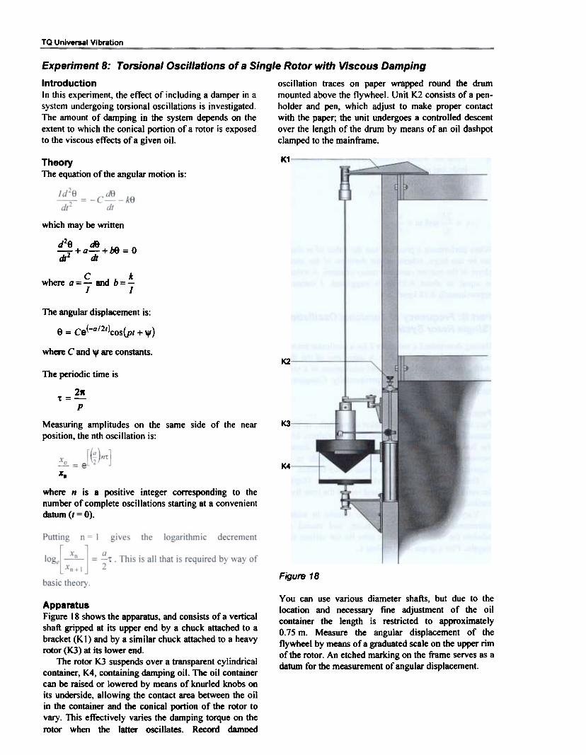
Experiment 8: Torsional Oscillations of a Single Rotor with Viscous Damping
Introduction oscillation traces on paper wrapped round the drumIn this experiment, the effect of including a damper in a mounted above the flywheel. Unit K2 consists of a pen-system undergoing torsional oscillations is investigated. holder and pen, which adjust to make proper contactThe amount of damping in the system depends on the with the paper; the unit undergoes a conUolled descentextent to which the conical portion of a rotor is exposed over the length of the drum by means of an oil dashpotto the viscous effects of a gjven oil. clamped to the mainframe.
K1TheoryThe equation of the angular motion is:
which may be written
d2e fA)dt2'+a"di+b8 = 0
C kwhere a=- and b=-
J J
The angular displacement is:
e = ce(-a/2t)cos(Pt + ",)
where C and . are constants.K2
The periodic time is
2K
Pt=
K3
K4XD
where n is a positive integer corresponding to thenumber of complete oscillations starting at a convenientdatum (I = 0).
Figure 18
You can use various diameter shafts, but due to thelocation and necessary fine adjustment of the oilcontainer the length is restricted to approximately0.75 m. Measure the angular displacement of theflywheel by means of a graduated scale on the upper rimof the rotor. An etched marking on the frame serves as adatum for the measurement of angular displacement.
ApparatusFigure 18 shows the apparatus, and consists of a verticalshaft gripped at its upper end by a chuck attached to abracket (KI) and by a similar chuck attached to a heavyrotor (K3) at its lower end.
The rotor K3 suspends over a transparent cylindricalcontainer, K4, containing damping oil. The oil containercan be raised or lowered by means of knurled knobs onits underside, allowing the contact area between the oilin the container and the conical portion of the rotor tovary. This effectively varies the damping torque on therotor when the latter oscillates. Record damned
Measuring amplitudes on the same side of the nearposition, the nth oscillation is:

TQ Universal Vibration
Part A: Determination of DampingCoefficient
Record a trace of the amplitude of oscillation showingdecay of the vibration due to the damping. The rate ofdescent of the pen previously carried out will provide asuitable time scale.
From the trace given in Figure 20, measure fivesuccessive amplitudes starting with the initial one (n =
0) and tabulate the results in Table 10 below.
ProcedureFill the cylindrical container K4 with oil to within10 mm of the top. Adjust the knobs underneath to levelthe oil surface with one of the upper graduations on theconical portion of the rotor, K3. A depth, d of 175 mmis suggested for maximum damping. Details of thegraduations on the rotor are in Figure 19.
Xn
(mm)
~.I&'.
log.n
i12~~"
0~~~~~Xs=
Table 10
ResultsPlot a graph of lo8e (xo/ xn) to a base of n. Confim1 that
the damping is viscous, and that the slope of the line isequal to (at/2) (the logarithmic decrement).
The period can be found by timing a convenientnumber of oscillations using a stopwatch, whereuponthe constant, a, is detennined and hence the value of thedamping coefficient (the torque per unit angularvelocity) in Nm/rad/s-i. The polar moment of inertia ofthe rotor is detennined as in Experiment 7.
Select and fit a suitable shaft, noting the length of theshaft between the two inside faces of the chuck, togetherwith the diameter of the shaft. Allow the pen to fall, andmeasure the rate of descent of the pen (in mm/second)by timing the descent of the pen over a fIXed length ofpaper, using a stopwatch.
The system is now ready for recording torsionaloscillations. Raise the pen to the top of the paper on thedrum and rotate the rotor to an angle of approximately40° and then release. A trace of the oscillations can beobtained by bringing the pen into contact with the paperusing the thumbnut on the support and allowing the pento descend.
Part B: Investigation of how the DampingCoefficient depends on the Depth ofImmersion of the Rotor in the Oil
Repeat Part A for each oil level as defined by the sevengraduations on the conical portion of the rotor.
The damping coefficient depends on the area A ofthe curved surface of the conical portion of the rotorexposed to viscous damping. This area is equal to 1V/,where r is the radius of base of core and / is the slant
height equal to [r2-;-j;i.Plot a graph of damping coefficient to a base of A
times mean radius.
ResultsTabulate these as in Table II
Figure 20

TQ Universal Vibration
Mean radius
rm (mm)
Area A
(mm2)A.rm
(mmJ)Perlod'f
(s)Damping
coefficientr
(mm)-~25.037.5
~82.5
~87.5-
Constanta
~~18.75
25.00
~~~.75
Table 11 Results of torsional oscillation with viscous damping
~g
1~.'50c.
~c~
!..~e-s~c"Q.E.
Q
0 100 200 300 400 LDwnplng.,.. x eff8Ct1ve (me.n) radius mm x 10
Figure 21
State the probable relationship between the twoparameters.

TQ Universal Vibration
Experiment 9: Torsional Oscillations of Two Rotor System
Introduction chucks fitted for use with shafts of various diameters.With the addition of a second rotor, the apparatus Since both rotors axles are fixed to their respectivedescribed in Experiment 7B can be used to investigate vertical members, the length of the shaft may not bethe oscillation of a two rotor system. For such a system varied but three shafts of different diameter are suppliedthe periodic time is: and three combinations of different inertias are possible.
~t-~ GJ(/. + /2
whereII = Moment of inertia of the rotor 1;h = Moment of inertia of rotor 2;L = Length of the shaft between the rotors;G = Modulus of rigidity of the material of the shaft;J = Polar second moment of area of the shaft
section.
ProcedureOne of the shafts clamps between the two rotors H. andH2 of predetennined inertia. Record the effective lengthof the shaft measured between the jaws of the chucks.Carefully tighten the chucks to ensure that neither rotorcan slip relative to the shaft.
Rotate each rotor through a small angle in oppositedirections and then release. Torsional oscillations of thesystem are thereby set up and the time for 20oscillations recorded.
The periodic time of the system may be determinedand compared with the theoretical value given by thefonnula quoted in the introduction. Detennine themoments of inertia of the rotors the method described inExperiment 7.
Results
Polar second moment of area J = ~d4
The generally accepted value of G for steel is 82 GPaand for g 9.81 m/s2.
Further ConsiderationsWhen oscillating torsionally, the two rotors oscillateback-to-back about a non-moving section of the shaft,called the node. It is instructive to locate the position ofthe node for a given pair of inertias and their shaft. Thiscan be done by introducing a third (dummy) rotor in theform of a cardboard disc (of negligible inertia) andmoving it along the shaft to a position where it becomesfixed in space.
The apparatus, as in Figure 22, is that of Experiment 7,with the bracket (II) replaced by a second rotor (HI)which is free to rotate on a axle fixed to the left-handvertical member of portal frame. Both rotors have
Time for 20oscillations-
Theoretical value of
periodShaft diameter
mm11
k~!!!~-
12
-~~Period 't
3.17~
~4.76
_6.35
Table 12

TQ Universal Vibration
Experiment 10: Transverse Vibration of a Beam with One or More Bodies Attached
IntroductionThe frequency of transverse vibrations of a beam withbodies attached is identical to the critical (whirling)speed of a shaft of the same stiffness as the beam,carrying rotors of masses which COITespond to those ofthe bodies on the beam.
One has to think in terms of small size rotors,otherwise gyroscopic effects are involved. In the case ofa beam with just one body attached, the basic theory isthe same as that in Experiment 6. For a beam with twoor more bodies attached, other methods can determinethe frequency of free transverse vibrations. Examplesare as follows:
leads to the precision speed control unit, which applies awjde range of exciting frequencies to the beam.
Clockwise rotation of the control knob on the speedcontrol unit wjll increase the speed of dte motor - thusincreasing the out-of-balance rotating force produced bythe unbalanced discs. As the speed increases asindicated by the speed meter on the control unit. thebeam begins to vibrate transversely. Over a discreteband of frequencies increasingly larger amplitudes ofV10ration are produced which reach a peak at afrequency corresponding to the frequency of free naturaltransverse vibration of the system, i.e. beam plus addedcomponents.
Part A: Transverse Vibration of a Beam
ProcedureSuspend bodies of different size mass, m, below themotor. For each mass m, adjust the speed control untilthe beam vibrates at its natural frequency.
In order to determine accurately the exact value onthe speed meter, it is expedient to take the beam throughthe range of excessive amplitudes several times, notingthe limits of the range. From these, we can locate thefi'equency at which the amplitude and resultant noiseappears greatest. Record your observations in Table 13.
Rayleigh or energy method (gives good results);Dunkerley equation (only approximate, but quiteadequate);Rigorous (accurate) analysis (arduous);Experimental analysis, using the equipmentdescribed below, (fairly simple and quick).
ApparatusThe basic apparatus for dris experiment is in Figure 23.A bar of steel of rectangular cross-section (E6) issupported at each end by trunnion blocks. The left-handsupport (01) pivots in two baII bearings in a housinglocated on the inside face of the vertical fi'ame member.
Mass m
kCJ
Frequency((Hz)
1~ x 10f
Table 13 Table of results for Experiment 10A
to a base of m gives a straight line, asResultsA graph of (1/ fin Figure 23.
The intercept on the vertical axis is equal to \
Natural frequency of the system, i. added components.
Natural frequency of the beam by itself
e. Deam
Dunkerley's equatioris given by:
applicable to this situatior andThe right-hand support consists of two roller bearings,which are fi'ee to move in a guide block located on theinside face. At the centre of the beam bolt a small motorcarrying two 'out-of-balance' discs (part of ExcitorMotor and Speed Control unit). Connect the motor via
+

TQ Universal Vibration
Here Ji = natural frequency of a corresponding lightbeam with mass m attached. Clearly when
m = 0, Ji = 00 and/= h
Pan B: Damped Transverse Vibration of aBeam
IntroductionDamping forces are counteracting forces in a vibrationsystem, which gradually reduce the motion. Dampingoccurs in all natural vibrations and may be caused byCoulomb friction (rubbing between one solid andanother), or viscous resistance of a fluid as in thisexperiment on damped transverse vibration of a beamwhere a dashpot is use.
Evaluate and compare with the theoretical valueobtained from:
f~
~
fb =
where
L = Length of the beam (m);F = Modulus of elasticity of material of the beam
(N/m1;I = Second moment of area of the beam section;mo = Mass of the beam by itself (kg); no masses
~ - attached.
ApparatusThis is shown in Figure 23 (the same set up as forExperiment lOA, but with certain additions). In thisexperiment you will require the amplitude of vibrationand phase angle. Fit a dashpot (02) and its support (E2)to the beam to create damping. Use the contactor (E5)with its vertically mounted micrometer to determine theamplitude and phase angle very accurately at anyexciting frequency. The electric circuit, of which astroboscope is a part, completes when the contactelement (E5) touches the plunger of the micrometer.
Also, from the graph, when the system is not vibrating(period t = 0) f = 00 and 1/ r = O. The corresponding
value of mass m is then equal to me, the equivalent massof the beam. me = Amo ' where A is a constant.
Determine the value of A. How does it compare withthe generally accepted value ofO.5?
Further ConsiderationsWe can test the validity of the Dunkerley equation in itsmore familiar form by moving the motor with out-of-balance discs away from the centre of the beam andattaching a heavy body of known mass at some otherpoint on the beam. The Dunkerley equation thenbecomes:
j = -j["i;11J:ii ,+ '~
The h in this equation could be the variable parameterand a graph plotted similar to the one described above.A special block for attaching extra masses to the beamand a suitable vibration generator of variable frequency(not supplied with the standard equipment) would berequired to perform this additional test.
ProcedureAllow the speed control unit time to warm-up, thenadjust the micrometer plunger so that it just touches thecontactor. When the stroboscope switches to externalstimulus, a discharge occurs on contact. Take themicrometer reading. Use this value as a datum positionfrom which values of amplitude may be determined.
Energise the motor to produce a definite amplitudeat a predetermined frequency. To determine theamplitude, lower the micrometer head and then bring upagain to produce contact. It is important that thestroboscope discharges at a uniform frequency, socareful adjustment must be made to ensure steadyconditions. At this point. find the amplitude of thevibration by comparing the new micrometer readingwith that of the original datum position.
You may also fmd the phase angle by focusing thestroboscope on the graduated disc on the motor shaft.Since the stroboscopic discharge should be at afrequency corresponding to the rotational speed of themotor, the disc may be effectively stopped and thephase angle corresponding to the datum mark on themotor read off. By following this procedure for a rangeof frequencies, you can assess the effect of damping byvarying the piston area of the dashpot and thus alteringthe damping characteristics of the system.
Rotate the two orifice plates inside the dashpotrelative to one another to vary the effective area.Compare the results obtained with these settings with anundamped condition (the system minus dashpot). Plotgraphs of amplitude and phase angle against thefrequency ratio, ro/OOn i.e. (exciting frequency/natural
frequency).
Note: At low frequencies, phase angle may not beobtainable.
Mass m kg
Figure 24 Graph of 1/r against m for the system

Ta Universal Vibration
Results Motor speed
(rev/mln)
Phase angle
log (O)
Amplitudex max. (mm)Motor speed
(rev/mln)
Phase angle
log (O)
Amplitudex max. (mm)
ww
~
..
~eoo
1.QQ...
~
~
~
~
121.9.
~
~
~
~
.~1075
1100
~
~1400
~
~
~~
~~~c.!!L
~
~
~
~
.~
~
~
~
~
~
JJ.!!!.
).l!!l:
1300
~
~
~
.~
2500Table 16
Table 14
Motor speed
(rev/mln)
Phase angle
log (O)
Amplitudex max. (mm)w
~~..lQQ.~~~~~~~~1055~12!§.~~~~~~~2500
The results, in Tables 14 to 16, show the effect ofincreasing damping on amplitude and phase angle. Foreach damping condition a graph of amplitude againstfrequency can be plotted, from which a value for thenatural frequency for each damping condition can befound. Typical values obtained in this way are asfollows:
No damping 17.36 HzLight damping 17.50 HzHeavy damping 17.58 Hz
and from these values the frequency ratio can be foundbeing the exciting frequency/natural frequency. Figures25 and 26 are typical graphs of amplitude and phaseangle plotted against frequency ratio.
Table 15

TQ Universal Vibration
0.5 1.0 1.5t. (Forclna freQuency)fn (Natural frequency)
2.00
Figure 26
1.0 1.5sg, (ForcinG freQuency)
CD. (Natural frequency)
2.00.5
Figure 25

TQ Universal Vibration
Experiment 11: Undamped Vibration Absorber
fixed equidistant from the midpoint of the horizontalcantilever. The distance apart of the bodies varies untilthe system is 'tuned'.
IntroductionExcessive vibrations in engineering systems aregenerally undesirable and therefore avoided for the sakeof safety and comfort. It is possible to reduce untowardamplitudes by attaching to the main vibrating syStem anauxiliary oscillating system, which could be a simplemass-spring system or pendulum. In this experiment,you will examine the vibration absorbability of a doublecantilever system.
Apparatus
ProcedureFor a given frequency, the masses of the vibrationabsorber are adjustable along their cantilevered leafspring so that the energy of vibration tJansmits to theabsorber and the amplitude of the main (primary)system, i.e. the motor and beam, is reduced to zero.
The aim is to detennine the length I, the distance ofthe centre of each of the bodies from the midpoint of thecantilever so that the natural frequency of transversevibration of this sub-system con-esponds to the runningspeed of the main (primary) system, i.e. the motor andthe beam.
The fonnula for detennining I is:
f=~~2n V.m13'
Heref = Natural frequency of the sub (auxiliary)
system;m = Mass of each of the bodies;EI = Flexural rigidity oftbe double cantilever.
Figure 27
Figure 27 shows the vibration absorber (GI) clampedbelow the motor. It comprises two bodies of equal mass

TQ Universal Vibration
Experiment 12: Forced Vibration of a Rigid Body - Spring System with Negligible Damping
Amplitude:
IntroductionWhen external forces act on a system during itsvibratory motion, it is termed forced vibration. Underconditions of forced vibration, the system will tend tovibrate at its own natural frequency superimposed uponthe frequency of the excitation force.
Friction and damping effects, though only slight arepresent in all vibrating systems; that portion of the totalamplitude not sustained by the external force willgradually decay. After a short time, the system willvibrate at the frequency of the excitation force,regardless of the initial conditions or natural frequencyof the system. In this experiment, observe and comparethe natural frequency of the forced vibration of arectangular section beam with the analytical results.
Resonance occurs when b - <Ii = o. So the critical
angular velocity of the motor is given by .Jb.Note that in practical circumstances the amplitude,
although it may be very large, does not become infmitebecause of the small amount of damping that is alwayspresent.Theory
Apparatus~1
t.D&- 05.
-Spring!09,
Figure 28 I'01
D102'
D3 [J6-:fWeight
t
The system is shown in Figure 28 and comprises of:
1. A beam AB, of length b, sensibly rigid, of mass m,freely pivoted at the left-hand end.
2. A spring of stiffi1ess S attached to the beam at thepoint C.
3. A motor with out-of-balance discs attached to thebeam at D.
. -5 J
-&..I.- ..! S- S.I
T..
M = mass of the motor including the two discs.
'"The equation of the angular motion is:
Figure 29
mLZ1I, ~ MLl +
The apparatus shown in Figure 29 consists of arectangular beam (D6), supported at one end by atrunnion pivoted in ball bearings located in a fIXedhousing. The outer end of the beam is supported by ahelical spring of known stiffness bolted to the bracketC I fixed to the top member of the frame. This bracketenables fine adjustments of the spring, thus raising andlowering the end of the beam.
The Excitor Motor and Speed Control (E II) rigidlybolts to the beam with additional masses placed on theplatform attached. Two out-of-balance discs on theoutput shaft of the belt driven unit (04) provide theforcing motion. The forcing frequency adjusts by meansof the speed control unit.
the moment of inertia of the system about the pivot axis,where:
e = Angular displacement of the beam;F 0 = Maximum value of the disturbing force;ro = Angular velocity of rotation to the discs.
The above equation reduces to the fonD:
d29
7+ ho9 = Asinro/

TQ Universal VIbration
unit time (i.e. the frequency) of the forced vibrationbeam.
You need to known the speed of the paper on thechart recorder. To obtain this, record a trace for 20seconds, for example, then measure the length of thetrace, thus calculating the speed in rnrn/s.
Determine the values of the relevant parameters asdescribed in the theory: lengths £., ~ magnitude of themasses m and M, also the stiffness of the spring.
Results and CalculationsUsing a stopwatch, time the linear speed of the drum
for 20 vibrations and determine the time for one cycle(period of vibration). Using the two different methodsdetennine the corresponding frequency. Calculate therelevant moment of inertia.
The chart recorder (07) fits to the right-hand verticalmember of the frame and provides the means ofobtaining a trace of the vibration. The recorder unitconsists of a slowly rotating dnun driven by asynchronous motor, operated from auxiliary supply onthe Excitor Motor and Speed Control unit. A roll ofrecording paper is adjacent to the dnun and is woundround the drum so that the paper is driven at a constantspeed. A felt-tipped pen fits to the free end of the beam;means are provided for drum adjustment so that the penjust touches the paper. A small attachable weight guidesthe paper vertically downwards. By switching on themotor, we can obtain a trace showing the oscillations ofthe end of the beam.
If the amplitude of vibration near to the resonancecondition is too large we can introduce extra dampinginto the system by fitting the dashpot assembly (partnumbers 02, 03 and 09) near to the pivoted end of thebeam.
If
C~
mmm
Table 17
The
Nm-J
kgm2
Sb=-=/A
It.,,:
Experimental ProcedureFirst plug the electrical lead from the synchronousmotor into the auxiliary socket on the Excitor Motor andSpeed Control. Adjust the handwheel of bracket C Iuntil the beam is horizontal and bring the chart recorderinto a position where the pen just touches the recordingpaper.
Switch on the speed control unit so the resuhingforced vibration causes the beam to oscillate. It has beenfound that a frequency of about 2 Hz is suitable, theposition of the motor can be adjusted accordingly. Thetime for 20 oscillations will then be approximately 10seconds. The chart recorder can record the number ofcycles performed by the beam in a given time(calculated, knowing the speed of the paper or, betterstill, by visual counting).
Bring the pen into contact with the paper, thenrecord the number of cycles and calculate the cycles per

TQ Univel$8l Vibration
Experiment 13: Free Damped Vibrations of a Rigid Body - Spring System
dashpot (D2) and its clamps along the beam, and also byrelative rotation of the two orifice plates in the dashpotto increase or decrease the effective area of the piston asin Experiment lOB.
IntroductionDuring vibrations, energy is dissipated and so a steadyamplitude cannot be maintained without continuousreplacement. Viscous damping in which force isproportional to velocity affords the simplestmathematical treatment.
A convenient means of measuring the amount ofdamping present is to measure the rate of decay ofoscillation. This is expressed by the term 'logarithmicdecrement', which is defined as the natural logarithm ofthe ratio of successive amplitudes on the same side ofthe mean position (see Figure 19).
In this experiment, the effect of the position of thedashpot and the corresponding damping coefficient areassessed in terms of the logarithmic decrement,measured by the decay in amplitude of a free vibrationof a beam.
ProcedureSwitch on the speed control unit and connect the leadfrom the motor of recorder unit 07 to the auxiliarysupply socket on the Excitor Motor and Speed Controlbox. Set the dashpot at distance L, (the distance fromthe trunnion mounting to the centre of the beam clamp09), and then pull the beam down a short distance,under the point of attachment of the spring, and release.
Bring the recording pen into contact with the paperto produce a trace of the decaying amplitude ofvibration and thus produce a trace of the decayingapplied amplitude on the chart recorder paper.
For a given piston area, select and obtain traces forvarious values of LI. Choose a different piston area andrepeat the process.
For each piston area and value L" use the trace toevaluate the logarithmic decrement. Find the periodictime of one complete oscillation, 't, in the mannerdescribed in Experiment 12. To recap:
Xo atLn- = -
xI 2
TheoryReferring to Figure 29, the disturbing force, FoSin !it is
replaced by a damping force cL) ~ downward. Thedt
equation of the angular motion becomes:
fAe = -(c49}L) - (s~e)~
where:
which can be put in the form:
9+a9+b9=OcIJ. andConstant a =-The theory from now on is identical to that set out in
Experiment 8 (the same symbols are used).
ApparatusThe apparatus is as shown in Figure 28 and Figure 29 inExperiment 12, except that the exciter motor is notrequired since only free vibrations are of interest. TheExcitor Motor and Speed Control unit is required inorder to drive the drum on the recorder unit D7. Thesystem is set vibrating freely by pulling down on thefree end of the beam a short distance (15 - 25 mm) andreleasing. Use the chart recorder to obtain a trace of justthree successive amplitudes on the same side of themean position. Vary the damping by moving the
From this the damping coefficient, c, the resisting forceper unit relative velocity can be determined.
ResultsEnter the results in Tables 18 and 19, one relating tomaximum damping (orifice plates in the dashpot set togive maximum area) and the other to minimumdamping.
. xAmplitude ratio -!-
x,
Damping coeff c
(N/m S.1)
xLog dec Log .Length L1 (m) Period 't (8) Constant a-
.!L~~~0.25
Table 18 Maximum damping

TQ Universal Vibr8tion
Damping coeff c
(HIm s-')
xAmplitude ratio -!..
X1
xLog dec Log-!-
x,Length L1 (m) Period 't (s) Constant a
I 0.10
0.15
Q.~
Table 19 Minimum damping
Plot, on the same graph, values of damping coefficient cagainst L 2. Figure 30 shows typical plots. Thelogarithmic decrement, hence the damping coefficientvaries according to the square of the distance from thedash pot. Adjusting the position of the dashpot on thebeam produces any degree of damping by consulting thegraph. This infonnation may be used in Experiment 14.
1:7
itE
Z
C.I
.MaxImum piston areeI . I
t7'
wii'A. E
S
M~rea~
7

TQ Universal Vibration
Experiment 14: Forced Damped Vibration of a Rigid Body - Spring System
!.m!!-Dm = £090IntroductionHaving established the effect of viscous damping onfree vibrations in the previous experiment, the effect onforced vibration is now analysed. To assess the relativemagnitude of the forced vibration, use the concept of'dynamic magnifier'. This is the ratio of the amplitudeof the forced vibration to the deflection produced if themaximum value of the disturbing force F is appliedstatically, under the same elastic restraint.
(3)
It can be shown that:
(4)
and in nearly all practical circumstances, damping is'light', and therefore a is sensibly small so
TheoryThe out-of-balance force is:
2mrwl (two discs)
.Dm = 1-{~/~}wherem = Mass corresponding to hole in each disc (kg);r = Radius to centre of hole (m);C1) = Angular velocity of discs (rad/s). (5)
(J) = Circular frequency of the forced vibration
(rad/s);~ = Circular frequency of free undamped vibration
(rad/s).
Note that the ratio of the rotational speed of the discs tothat of the motor is 22:72. Consider this whencalculating the angular velocity of the discs, (J) rad/s,from the speed indicated on the control unit.
Referring to Figure 29, the equation of the angularmotion is:
ApparatusFigure 29 shows the apparatus with the dashpot addedand the addition of an extra item: a plate clamped to theout-of-balance disc. The plate holds a piece of circularpaper.
The recording pen fits to pivot (08), which clampsto the upper member of the frame and clips above theframe when not in use. The pen makes a trace of thelocus of the point at any radius on the rotor. Since therotor is capable of vertical as well as rotationalmovement, you can obtain a trace from which the phaselag can be determined.
!_-J 9 = (Fsin(JX)4~_~e)f1- (~9~
Only the steady-state motion is of interest i.e.
{) = Asin(CIJt - 41)
~(b-w2r +<0202
Lfm =90
ProcedureThe natural frequency of the system is first found asdescribed in Part 4 of Experiment 13, by analysing thefree vibrations of the system, without the dashpot, froma trace produced on the chart recording unit (D7).
Fit the dashpot unit (D2) at a suitable point along thebeam to give a definite degree of damping (asdetermined in Experiment 13). Then rotate the exciterdiscs at a very low speed and obtain a datum trace onthe paper mounted on the plate attached to the nearsidedisc. Mark the position of the hole in the disc on thetrace.
Increase the speed of rotation to develop forcedvibration of reasonable amplitude in the beam. Obtain asecond 'dynamic' trace on the paper mounted on theplate. Also obtain a trace on the chart recorder at theright-hand end of the beam (as in Experiment 12) inorder to determine the amplitude of the vibrations.Repeat the procedure for different speeds below andabove the critical speed to show how the value ofdynamic magnifier varies with frequency for a givevalue of the damping coefficient.
(2)
where
k = 84 (torsional stiffness of the beam).
Deflections measured are those of the end B of the beamand are given by x = Le so:
which reduces to the standard fonn:
9+00+b9 = Asinrot

TQ Universal Vibration
the exciting force and the resulting vibration, thedynamic trace displaces along the datum linecorresponding to the out-of-balance force. Join up thepoints of intersection of the two traces and draw a linethrough the axis of rotation at right angles to determinethe phase lag 9 for the various speeds of rotation of thediscs.
ResultsTabulate the results as shown in Table 20 and 21, thecolumns numbering is for the purpose of thisexplanation only.
There are two tables, one for die case of nodamping, the other for a definite degree of damping.Present a specimen of calculations in respect of eachtable.
Detennine the phase lag from the traces recorded on thepaper as shown in Figure 31. Note that the dynamictrace displaces relative to the axis of rotation due to thevibration of the beam. If there is no phase lag between
(I)
locity
(rad/s)
!!!!l.w
Wn
(iv) (vi) ~vm~ ~v Ph-. angle lag
(O) II Excitor motor
speed (rev/min)
Am plltudeX- (mm)
Static deflection
(mm)
I Dynamic magnifier
(Dm)
~~~~650660m.~~a
Table 20 No damping
'II II
Angular velocityof disc m (rad/s)
Jill}w
w
I (Iv)
Amplitude
x- (mm)
(vi) (vII)
I Dynamic magnifierI (D",) I
I PM" ;~Ie lag
I (O)
I Excitor motor
speed (rev/min)Static deflection
(mm)
~560
I ~ II 625
m~~zooI -900
Table 21 Dampino
column (iii). Obtain the amplitude column from theb'ace on the drum recorder 07. The corresponding phaseangle lag, is obtained in the manner already described.Use Equations (2) and (3) to find the 'Static Deflection';find Dm using Equation (4).

Ta Universal Vibration
Plot graphs of Dynamic Magnifier Dm and Phase Angleeach to a base of the ratio oi~. Figures 32 and 33 showtypical graphs. Obtain similar results for differentdegrees of damping.
180
150
120C~.190
60
30 ,.,
0 ~- - ~- I J .0.85 0.90 0.95 1.00 1.05 1.10 1.15
m/m.
Figure 33 Phase lag against ratio oi~

SECTION 4: REFERENCES
J. Hannah and R.C. Stephens"Mechanics of Machines - Advanced Theory and
Examples"Edward Arnold 1972 London
W . T. Thompson"Theory of Vibration"Allen & Unwin 1981 London.
W.W. Seto"Mechanical Vibrations"Schaum Outline Series, McGraw-HilI, 1964 USA.
J.L. Meriam"Dynamics - 2nd Edition"John Wiley 1971 USA.
J.P. Den Hartog"Mechanical Vibrations"McGraw-Hili 1956 USA.
S.P. Timoshenko"Vibration Problems in Engineering"4th Edition, Wiley 1974 W. Sussex, UK.

APPENDIX: EXCITOR MOTOR AND SPEED CONTROL
Operation and Use overrides the front panel conb'ol. Connections to theDIN connector are:
PIN 1 Potentiometer SUpp1yPIN 2 'earth PIN 3' wiper
A Speed Control Unit comes as part of the UniversalVibration Apparatus. The unit provides complete bi-directional drive and high precision speed control of theMotorffacho-generator under all nonnal conditions,using a closed-loop control system. An amplifier detectsany difference between the motor speed and the inputcommand vohage set by the 'Set Speed' control on thefront panel. The amplifier drives the motor until thedifference is approximately zero. Provisions for the veryhigh currents for acceleration and deceleration areautomatical. The speed control can maintain speedsfrom 3000 rev/min down to less than lrev/min whenused with the Motorffacho-generator.
The front panel of the unit contains a 'set speed'control, a fully calibrated speed meter incorporatingautomatic range switching, a motor forward/reverseswitch, mains input socket and switch, d.c. motor powersocket, external control and an auxiliary oUtput socketand switch.
Connection and Operation
Motor/Tacho-Generator, TM16f (F1)
Ensure all switches are in the 'oW position before
proceeding and the motor and/or recorder has been
physically installed as outlined previously.
I. Connect the speed controller to a suitable mains
supply.2. Connect the motor to the socket marked 'd.c.
motor'.
3. Switch the unit on and adjust ilie motor speed using
ilie 'Set Speed' control.
The unit will automatically switch to the COITeCt speed
scale.
Set Speed ControlA ten turn control giving increasing speed withclockwise rotation.
Drum Recorder, TM16d (D7)I. Switch the unit off.2. Connect the drum recorder to the socket marked
either 'auxiliary output' or 'drum supply 240 Y'.3. As (3) above.4. Switch on the drum recorder when requiredSpeed Meter
The speed meter has two ranges, 0 - 1500 rev/min and0 - 3000 rev/min. Switching between these occursautomatically when the motor speed increases above ordecreases below 1500 rev/min. The lamps below themeter indicates its range.
Motor Forward/Reverse SwitchYou can reverse the direction of rotation of the motor atany load or speed without damage. It is, however,recommended that the motor is stopped beforereversing.
External ControlA DIN connector provides connection for an externalset speed control (I k.o.) which. when connected,
Connecting the Speed Control Unit inConjunction with a Stroboscope (not supplied)I. Switch the unit off.2. Plug the BNC T -piece into either of the sockets on
the portal frame. Connect the 'trigger supply'socket on the speed controller to dte T -piece andconnect the T -piece to a stroboscope using the BNCto jack lead.
3. Connect the leaf contact on the motor to the otherBNC socket on the portal frame via its lead.
4. As (3) above. The stroboscope will flash once everyrevolution of d1e motor.
5. Connect the stroboscope to a suitable mains supply.