eds/dm35, hub
TRANSCRIPT

PR
OD
UC
T I
NF
OR
MA
TIO
N
EDS/EDM35, sHub®
EXCEPTIONAL PERFORMANCE FOR SERVO DRIVES: MOTOR FEEDBACK SYSTEMS WITH HIPERFACE DSL®
Motor feedback system rotary HIPERFACE DSL®

M o t o r f e e d b a c k s y s t e M s | s I c k 8023528/2021-08-11Subject to change without notice
2
eds/edM35 MOTOR FEEDBACK SYSTEMS ROTARY HIPERFACE DSL®
Product descriptionThe digital HIPERFACE DSL® interface has played a significant role in shaping drive technology over recent years. EDS/EDM35 motor feedback systems come with HIPERFACE DSL® and ensure out-standing performance for high-precision servo drives used in safety applications. Fitted with a standardized mechanical interface, they are highly flexible, par-ticularly when used in conjunction with EES/EEM37 motor feedback systems.
EDS/EDM35 systems have a newly developed optical scanning system with dual-channel scanning and are highly resistant to shocks and vibrations. Fea-tures such as safe singleturn absolute positioning and electronic type labels EDS/EDM35 make them the ideal solu-tion for a wide range of applications, for example in the packaging and machine tool industries.
At a glance• Optical motor feedback system with
HIPERFACE DSL®
• Up to 24-bit resolution per revolution and 4,096 revolutions with the multi-turn system
• Certified according to SIL2 and PL d• Status monitoring and mission time
histogram; temperature, speed, and revolution data are stored throughout the service life of the device
Your benefits• A single model with different perfor-
mance levels allows system suppliers to implement a variety of applications using only one type of encoder
• EDS/EDM35 motor feedback sys-tems are ideal for use in high-preci-sion, dynamic applications
• The 13-bit safe absolute singleturn resolution meets the requirements of tomorrow’s safety servo drives
Motor feedback systemsMOTOR FEEDBACK SYSTEMS ROTARY HIPER-FACE DSL®eds/edM35
Subject to change without notice
.
EXCEPTIONAL PERFORMANCE FOR SERVO DRIVES: MOTOR FEEDBACK SYSTEMS WITH HIPERFACE DSL®
Additional information
Fields of application . . . . . . . . . . . . . . .3
Detailed technical data . . . . . . . . . . . .3
Type code . . . . . . . . . . . . . . . . . . . . . . .5
Ordering information . . . . . . . . . . . . . .5
Dimensional drawings . . . . . . . . . . . . .6
Attachment specifications . . . . . . . . . .6
PIN assignment. . . . . . . . . . . . . . . . . . .7
Technical Description. . . . . . . . . . . . . .8
Diagrams . . . . . . . . . . . . . . . . . . . . . . . .8
Supported resources for HIPERFACE DSL®. . . . . . . . . . . . . . . . . . . . . . . . . . . .8
Supported access levels . . . . . . . . . .10
Overview of warnings and fault indica-tions . . . . . . . . . . . . . . . . . . . . . . . . . . .10
Recommended accessories . . . . . . 11
- www.sick.com/eds_edM35For more information, simply enter the link or scan the QR code and get direct access to technical data, CAD design models, operating instructions, software, application examples, and much more.
ABCDEF
HIJKLMNOPQRST

M o t o r f e e d b a c k s y s t e M s | s I c k8023528/2021-08-11Subject to change without notice
3
MOTOR FEEDBACK SYSTEMS ROTARY HIPERFACE DSL® eds/edM35
Fields of application• Packaging industry • Machine tools
Detailed technical data
Performance
absolute sin-gleturn20 bit
absolute sin-gleturn24 bit
absolute Multiturn20 bit
absolute Multiturn24 bit
resolution per revolution 20 bit 24 bit 20 bit 24 bit
Number of the absolute ascertainable revolutions
1 4,096
Signal noise (σ) ± 3 ″ 1) ± 1 ″ 1) ± 3 ″ 1) ± 1 ″ 1)
signal accuracy ± 50 ″ 2) ± 25 ″ 2) ± 50 ″ 2) ± 25 ″ 2)
speed when switching on/resetting the motor feedback system
≤ 6,000 min-1
available memory area 8,192 Byte1) Repeatability standard deviation in accordance with DIN 1319-1:1995.2) In accordance with DIN ISO 1319-1, position of the upper and lower error limit depends on the installation situation, specified value refers to a symmetrical
position, i.e. deviation in upper and lower direction is the same.
Interfaces
code sequence Increasing, when turning the shaft For clockwise rotation, looking in direction “A” (see dimen-sional drawing)
communication interface HIPERFACE DSL®
Initialization time ≤ 500 ms 1)
Measurement external temperature resistance
32-bit value, without prefix (1 Ω) 0 ... 209.600 Ω 2)
1) From reaching a permitted operating voltage.2) Without sensor tolerance; at –40 °C ... +160 °C: NTC +-2K; PTC+-3K (KTY84-130/PT1000). For additional conversion function of PT1000 to KTY84/130, see
technical description.
Electrical data
for integrationabsolute singleturn
for integrationabsolute Multiturn
connection type Male connector, 4-pin Male connector, 4-pinMale connector, 8-pin
supply voltage 7 V ... 12 V
Warm-up time voltage ramp Max. 180 ms 1)
Power consumption ≤ 150 mA 2)
combinable with sHub® – – / l1) Duration of voltage ramp between 0 and 7.0 V.2) Current rating applies when using interface circuit suggestions as shown in HIPERFACE DSL ® manual (8017595).
Mechanical data
absolute sin-gleturn20 bit
absolute sin-gleturn24 bit
absolute Multiturn20 bit
absolute Multiturn24 bit
shaft version Tapered shaft
dimensions See dimensional drawing
Weight ≤ 100 g
Moment of inertia of the rotor 5 gcm²1) Temperature expansion, mechanical attachment.2) For SIL2 version.
ABCDEF
HIJKLMNOPQRST
M o t o r f e e d b a c k s y s t e M s | s I c k 8023528/2021-08-11Subject to change without notice
4
eds/edM35 MOTOR FEEDBACK SYSTEMS ROTARY HIPERFACE DSL®
absolute sin-gleturn20 bit
absolute sin-gleturn24 bit
absolute Multiturn20 bit
absolute Multiturn24 bit
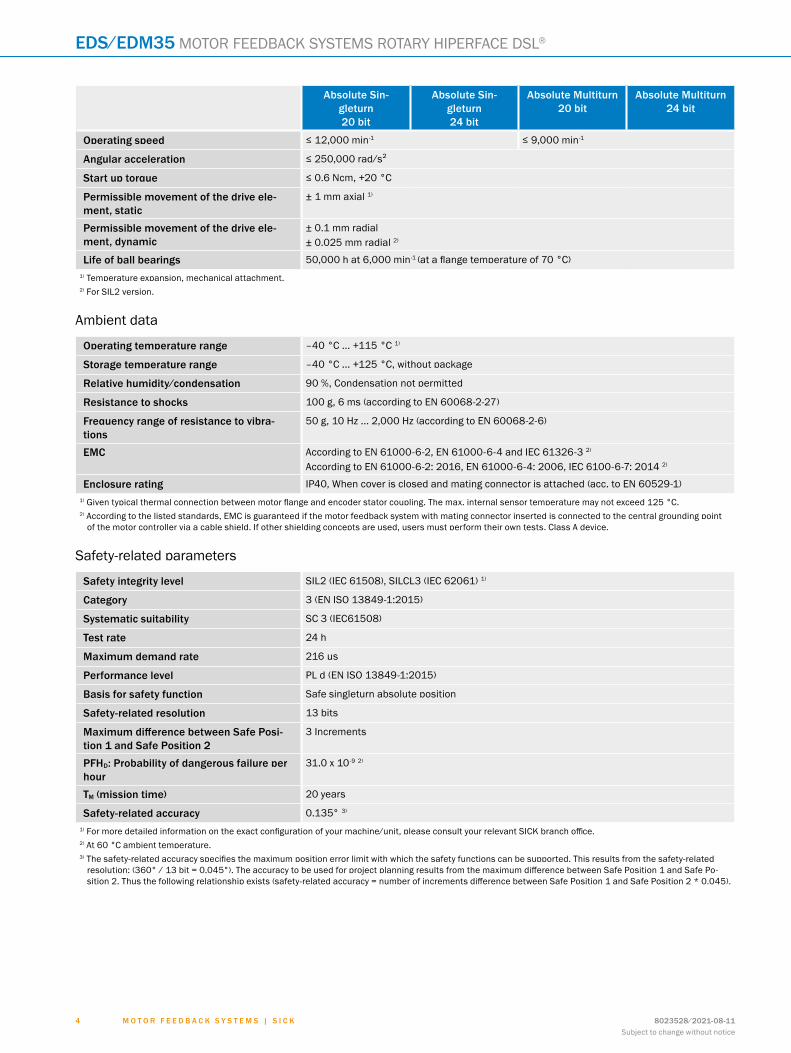
operating speed ≤ 12,000 min-1 ≤ 9,000 min-1
angular acceleration ≤ 250,000 rad/s²
start up torque ≤ 0.6 Ncm, +20 °C
Permissible movement of the drive ele-ment, static
± 1 mm axial 1)
Permissible movement of the drive ele-ment, dynamic
± 0.1 mm radial± 0.025 mm radial 2)
Life of ball bearings 50,000 h at 6,000 min-1 (at a flange temperature of 70 °C)1) Temperature expansion, mechanical attachment.2) For SIL2 version.
Ambient data
operating temperature range –40 °C ... +115 °C 1)
storage temperature range –40 °C ... +125 °C, without package
relative humidity/condensation 90 %, Condensation not permitted
resistance to shocks 100 g, 6 ms (according to EN 60068-2-27)
frequency range of resistance to vibra-tions
50 g, 10 Hz ... 2,000 Hz (according to EN 60068-2-6)
eMc According to EN 61000-6-2, EN 61000-6-4 and IEC 61326-3 2)
According to EN 61000-6-2: 2016, EN 61000-6-4: 2006, IEC 6100-6-7: 2014 2)
enclosure rating IP40, When cover is closed and mating connector is attached (acc. to EN 60529-1)1) Given typical thermal connection between motor flange and encoder stator coupling. The max. internal sensor temperature may not exceed 125 °C.2) According to the listed standards, EMC is guaranteed if the motor feedback system with mating connector inserted is connected to the central grounding point
of the motor controller via a cable shield. If other shielding concepts are used, users must perform their own tests. Class A device.
Safety-related parameters
safety integrity level SIL2 (IEC 61508), SILCL3 (IEC 62061) 1)
category 3 (EN ISO 13849-1:2015)
systematic suitability SC 3 (IEC61508)
test rate 24 h
Maximum demand rate 216 µs
Performance level PL d (EN ISO 13849-1:2015)
basis for safety function Safe singleturn absolute position
safety-related resolution 13 bits
Maximum difference between Safe Posi-tion 1 and safe Position 2
3 Increments
PfHd: Probability of dangerous failure per hour
31.0 x 10 -9 2)
tM (mission time) 20 years
safety-related accuracy 0.135° 3)
1) For more detailed information on the exact configuration of your machine/unit, please consult your relevant SICK branch office.2) At 60 °C ambient temperature.3) The safety-related accuracy specifies the maximum position error limit with which the safety functions can be supported. This results from the safety-related
resolution: (360° / 13 bit = 0.045°). The accuracy to be used for project planning results from the maximum difference between Safe Position 1 and Safe Po-sition 2. Thus the following relationship exists (safety-related accuracy = number of increments difference between Safe Position 1 and Safe Position 2 * 0.045).
ABCDEF
HIJKLMNOPQRST
M o t o r f e e d b a c k s y s t e M s | s I c k8023528/2021-08-11Subject to change without notice
5
MOTOR FEEDBACK SYSTEMS ROTARY HIPERFACE DSL® eds/edM35
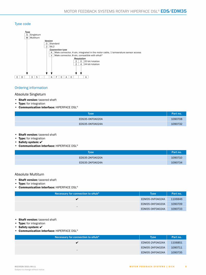
Type code
typeS SingleturnM Multiturn
Version0 Standard2 SIL2
connection typeK Male connector, 4-pin, integrated in the motor cable, 1 temperature sensor accessV Male connector, 8-pin, compatible with sHub®
resolution2 0 20 bit/rotation2 4 24 bit/rotation
E D 3 5 - K F 0 A 0 A
Ordering information
Absolute Singleturn• Shaft version: tapered shaft• Type: for integration• Communication interface: HIPERFACE DSL®
type Part no.
EDS35-0KF0A020A 1090708
EDS35-0KF0A024A 1090732
• Shaft version: tapered shaft• Type: for integration• Safety system: l• Communication interface: HIPERFACE DSL®
type Part no.
EDS35-2KF0A020A 1090710
EDS35-2KF0A024A 1090734
Absolute Multiturn• Shaft version: tapered shaft• Type: for integration• Communication interface: HIPERFACE DSL®
Necessary for connection to sHub® type Part no.
l EDM35-0VF0A024A 1106846
–EDM35-0KF0A020A 1090709
EDM35-0KF0A024A 1090733
• Shaft version: tapered shaft• Type: for integration• Safety system: l• Communication interface: HIPERFACE DSL®
Necessary for connection to sHub® type Part no.
l EDM35-2VF0A024A 1106851
–EDM35-2KF0A020A 1090711
EDM35-2KF0A024A 1090735
ABCDEF
HIJKLMNOPQRST
M o t o r f e e d b a c k s y s t e M s | s I c k 8023528/2021-08-11Subject to change without notice
6
eds/edM35 MOTOR FEEDBACK SYSTEMS ROTARY HIPERFACE DSL®
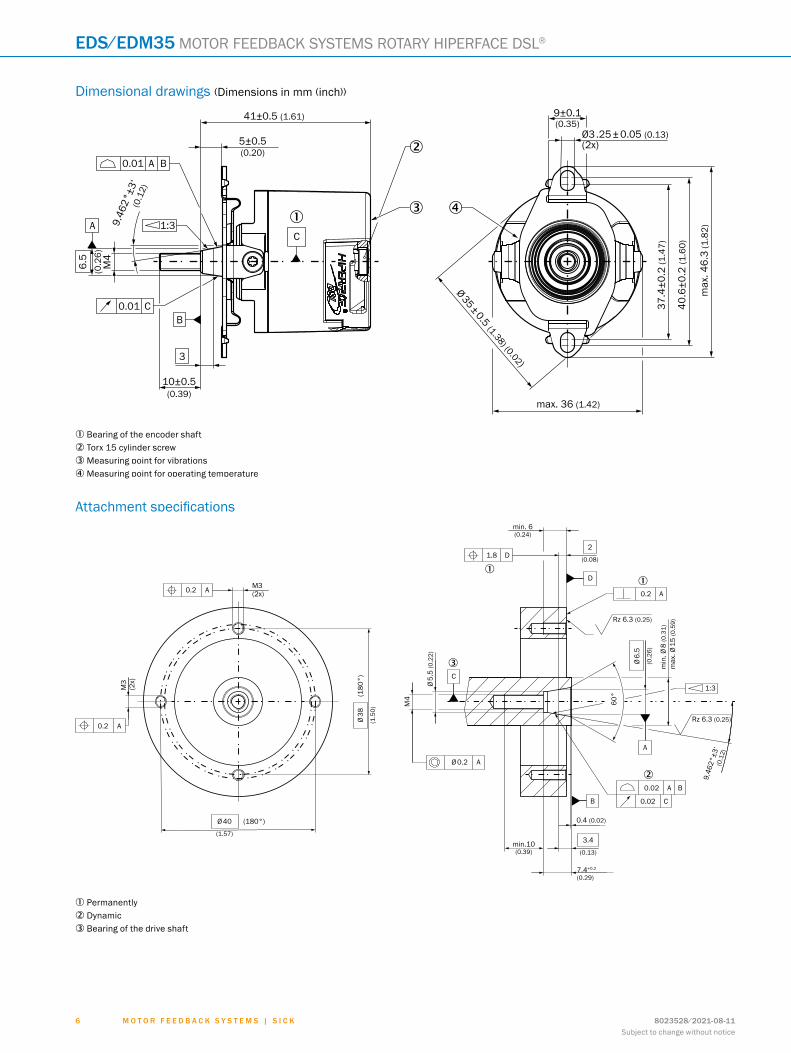
Dimensional drawings (Dimensions in mm (inch))
3 4
2
41±0.5 (1.61)
5±0.5(0.20)
6.5
(0.2
6)M
4
0.01 A B
A
C0.01
1:39.46
2°±3
‘(0
.12)
10±0.5(0.39)
B
3
9±0.1(0.35)
Ø3 .25 ± 0.05 (0.13)(2x)
Ø 35 ± 0.5 (1.38) (0.02)
max. 36 (1.42)
37.4
±0.2
(1.4
7)
40.6
±0.2
(1.6
0)
max
. 46.
3 (1
.82)
1
C
1 Bearing of the encoder shaft2 Torx 15 cylinder screw3 Measuring point for vibrations4 Measuring point for operating temperature
Attachment specifications
1
1
2
3
min. 6(0.24)
1.8 D
D
A
B
BA
AØ 0.2
2
(0.08)
0.2 A
Rz 6.3 (0.25)
Rz 6.3 (0.25)
Ø 6.
5
(0.2
6)
min
. Ø 8
(0.3
1)m
ax. Ø
15
(0.5
9)
1:3
60°
0.02
0.02 C
0.4 (0.02)
3.4
(0.13)
7.4+0.2
(0.29)
min.10(0.39)
C
Ø 5.
5 (0
.22)
Ø 38
(1.5
0)
Ø 40
(1.57)
(180°)
0.2 A
M3
(2x)
M3(2x)0.2 A
9.46
2°±3
‘(0
.12)
M4(1
80°)
1 Permanently2 Dynamic3 Bearing of the drive shaft
ABCDEF
HIJKLMNOPQRST

M o t o r f e e d b a c k s y s t e M s | s I c k8023528/2021-08-11Subject to change without notice
7
MOTOR FEEDBACK SYSTEMS ROTARY HIPERFACE DSL® eds/edM35
PIN assignmentSupply / Communication pin assignment
1 2 3 4
K connection typeIntegrated in motor cable = K
PIN signal explanation
1 Not connected - no function
2 +US/DSL+ Supply 7 V ... 12 V
3 GND/DSL- Ground connection
4 Not connected - no function
Recommended outer diameter of set of stranded wires: 2.8 mm ±0.3 mm
Recommended mating connector: JST (GHR-04V-S)
PIN assignment temperature sensor
2 1
K connection typeIntegrated in motor cable = K
PIN signal explanation
1 T+ Thermistor connection
1 T- Thermistor connection (to ground)
Recommended outer diameter of set of stranded wires: 2.2 mm ± 0.1 mm
Recommended mating connector: Harwin M80-8990205
Supply / Communication pin assignment
V connection type
PIN signal explanation
1 +US Supply
2 GND Ground connection
3 DSL- DSL negative
4 DSL+ DSL positive
5 RxD+
6 RxD-
7 TxD-
8 TxD+
Recommended mating connector: JST (GHR-08V-S)
ABCDEF
HIJKLMNOPQRST
M o t o r f e e d b a c k s y s t e M s | s I c k 8023528/2021-08-11Subject to change without notice
8
eds/edM35 MOTOR FEEDBACK SYSTEMS ROTARY HIPERFACE DSL®
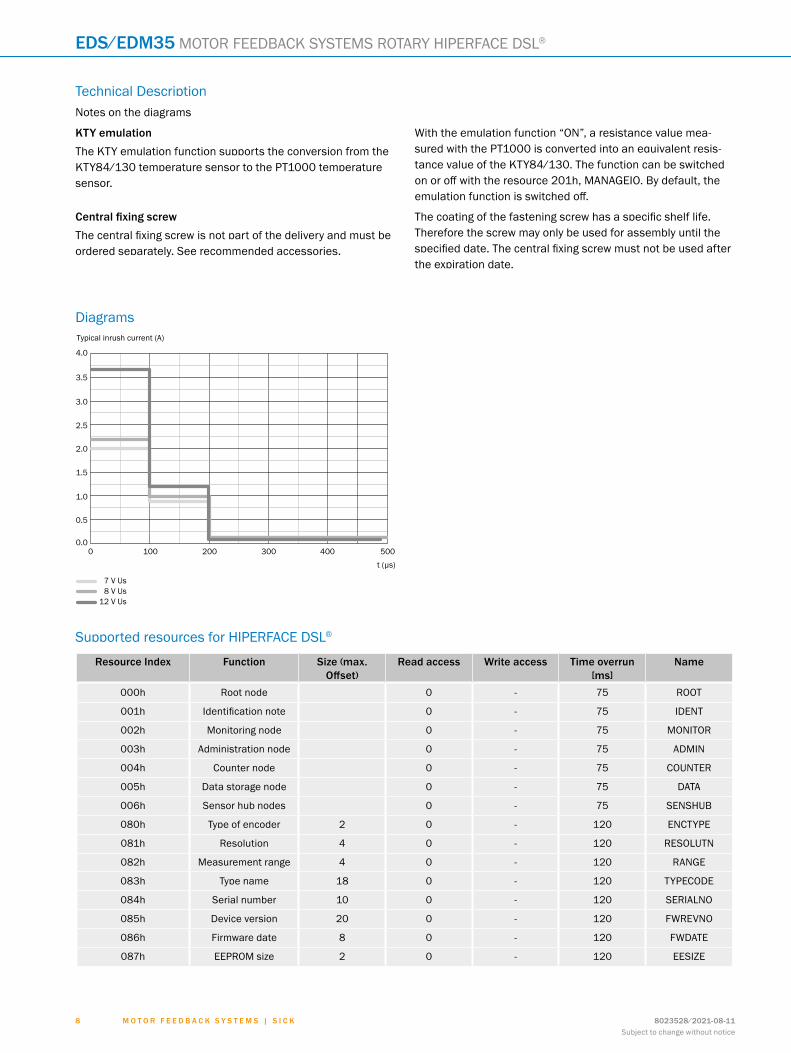
Technical DescriptionNotes on the diagrams
kty emulationThe KTY emulation function supports the conversion from the KTY84/130 temperature sensor to the PT1000 temperature sensor.
With the emulation function “ON”, a resistance value mea-sured with the PT1000 is converted into an equivalent resis-tance value of the KTY84/130. The function can be switched on or off with the resource 201h, MANAGEIO. By default, the emulation function is switched off.
Central fixing screwThe central fixing screw is not part of the delivery and must be ordered separately. See recommended accessories.
The coating of the fastening screw has a specific shelf life. Therefore the screw may only be used for assembly until the specified date. The central fixing screw must not be used after the expiration date.
Diagrams
50040030020010000.0
0.5
1.0
1.5
2.0
2.5
3.0
3.5
t (µs)
Typical inrush current (A)
4.0
7 V Us8 V Us
12 V Us
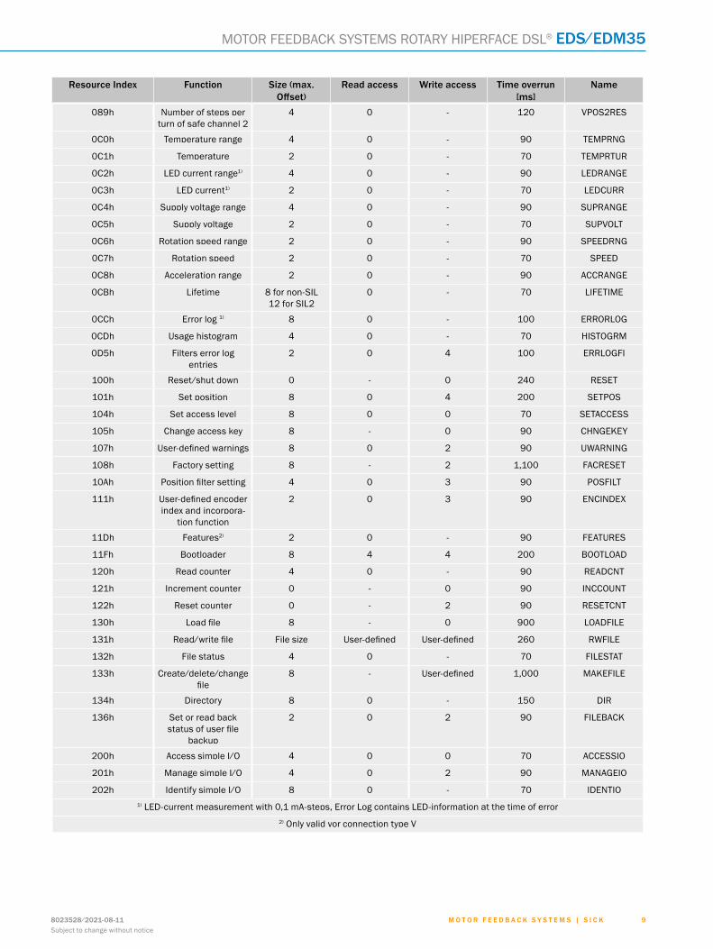
Supported resources for HIPERFACE DSL®
resource Index function size (max. Offset)
read access Write access time overrun [ms]
Name
000h Root node 0 - 75 ROOT
001h Identification note 0 - 75 IDENT
002h Monitoring node 0 - 75 MONITOR
003h Administration node 0 - 75 ADMIN
004h Counter node 0 - 75 COUNTER
005h Data storage node 0 - 75 DATA
006h Sensor hub nodes 0 - 75 SENSHUB
080h Type of encoder 2 0 - 120 ENCTYPE
081h Resolution 4 0 - 120 RESOLUTN
082h Measurement range 4 0 - 120 RANGE
083h Type name 18 0 - 120 TYPECODE
084h Serial number 10 0 - 120 SERIALNO
085h Device version 20 0 - 120 FWREVNO
086h Firmware date 8 0 - 120 FWDATE
087h EEPROM size 2 0 - 120 EESIZE
ABCDEF
HIJKLMNOPQRST
M o t o r f e e d b a c k s y s t e M s | s I c k8023528/2021-08-11Subject to change without notice
9
MOTOR FEEDBACK SYSTEMS ROTARY HIPERFACE DSL® eds/edM35
resource Index function size (max. Offset)
read access Write access time overrun [ms]
Name
089h Number of steps per turn of safe channel 2
4 0 - 120 VPOS2RES
0C0h Temperature range 4 0 - 90 TEMPRNG
0C1h Temperature 2 0 - 70 TEMPRTUR
0C2h LED current range1) 4 0 - 90 LEDRANGE
0C3h LED current1) 2 0 - 70 LEDCURR
0C4h Supply voltage range 4 0 - 90 SUPRANGE
0C5h Supply voltage 2 0 - 70 SUPVOLT
0C6h Rotation speed range 2 0 - 90 SPEEDRNG
0C7h Rotation speed 2 0 - 70 SPEED
0C8h Acceleration range 2 0 - 90 ACCRANGE
0CBh Lifetime 8 for non-SIL 12 for SIL2
0 - 70 LIFETIME
0CCh Error log 1) 8 0 - 100 ERRORLOG
0CDh Usage histogram 4 0 - 70 HISTOGRM
0D5h Filters error log entries
2 0 4 100 ERRLOGFI
100h Reset/shut down 0 - 0 240 RESET
101h Set position 8 0 4 200 SETPOS
104h Set access level 8 0 0 70 SETACCESS
105h Change access key 8 - 0 90 CHNGEKEY
107h User-defined warnings 8 0 2 90 UWARNING
108h Factory setting 8 - 2 1,100 FACRESET
10Ah Position filter setting 4 0 3 90 POSFILT
111h User-defined encoder index and incorpora-
tion function
2 0 3 90 ENCINDEX
11Dh Features2) 2 0 - 90 FEATURES
11Fh Bootloader 8 4 4 200 BOOTLOAD
120h Read counter 4 0 - 90 READCNT
121h Increment counter 0 - 0 90 INCCOUNT
122h Reset counter 0 - 2 90 RESETCNT
130h Load file 8 - 0 900 LOADFILE
131h Read/write file File size User-defined User-defined 260 RWFILE
132h File status 4 0 - 70 FILESTAT
133h Create/delete/change file
8 - User-defined 1,000 MAKEFILE
134h Directory 8 0 - 150 DIR
136h Set or read back status of user file
backup
2 0 2 90 FILEBACK
200h Access simple I/O 4 0 0 70 ACCESSIO
201h Manage simple I/O 4 0 2 90 MANAGEIO
202h Identify simple I/O 8 0 - 70 IDENTIO1) LED-current measurement with 0,1 mA-steps, Error Log contains LED-information at the time of error
2) Only valid vor connection type V
ABCDEF
HIJKLMNOPQRST
M o t o r f e e d b a c k s y s t e M s | s I c k 8023528/2021-08-11Subject to change without notice
1 0
eds/edM35 MOTOR FEEDBACK SYSTEMS ROTARY HIPERFACE DSL®
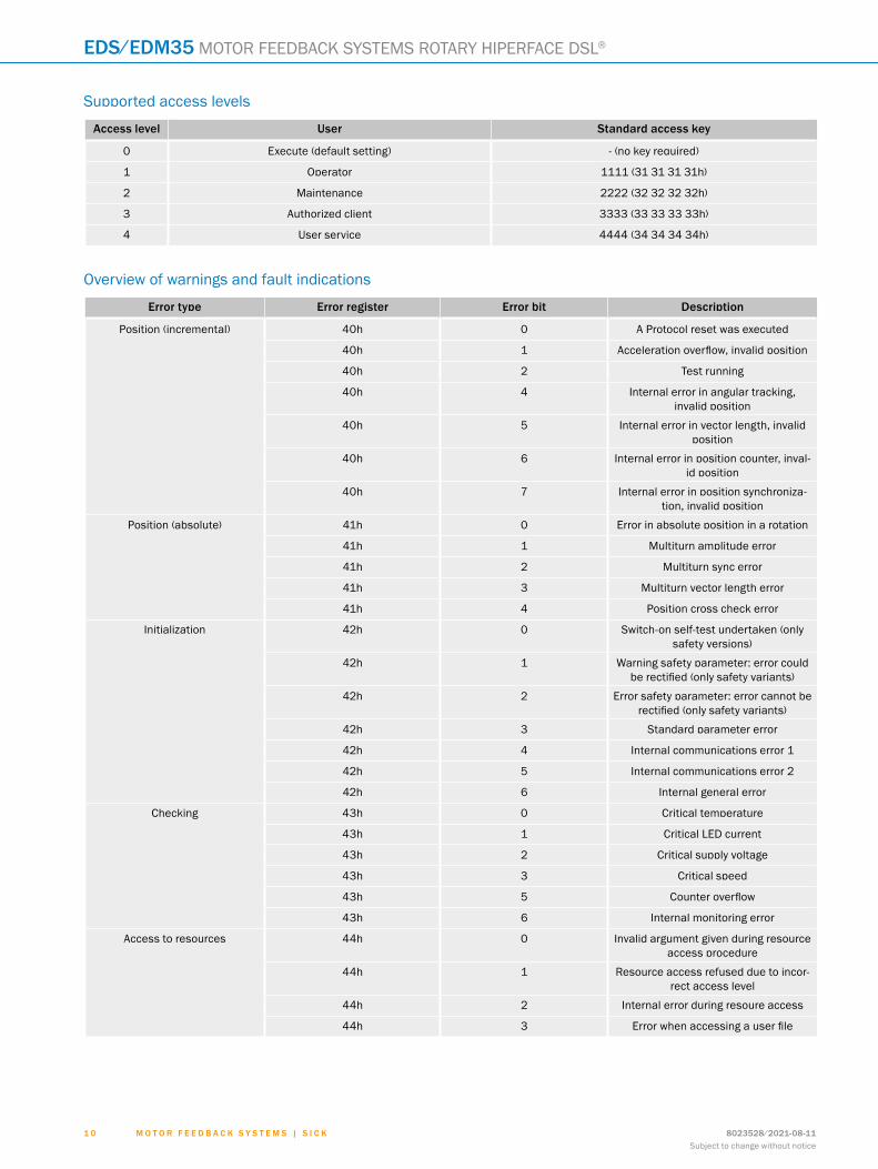
Supported access levels
access level User standard access key
0 Execute (default setting) - (no key required)
1 Operator 1111 (31 31 31 31h)
2 Maintenance 2222 (32 32 32 32h)
3 Authorized client 3333 (33 33 33 33h)
4 User service 4444 (34 34 34 34h)
Overview of warnings and fault indications
error type error register error bit description
Position (incremental) 40h 0 A Protocol reset was executed
40h 1 Acceleration overflow, invalid position
40h 2 Test running
40h 4 Internal error in angular tracking, invalid position
40h 5 Internal error in vector length, invalid position
40h 6 Internal error in position counter, inval-id position
40h 7 Internal error in position synchroniza-tion, invalid position
Position (absolute) 41h 0 Error in absolute position in a rotation
41h 1 Multiturn amplitude error
41h 2 Multiturn sync error
41h 3 Multiturn vector length error
41h 4 Position cross check error
Initialization 42h 0 Switch-on self-test undertaken (only safety versions)
42h 1 Warning safety parameter: error could be rectified (only safety variants)
42h 2 Error safety parameter: error cannot be rectified (only safety variants)
42h 3 Standard parameter error
42h 4 Internal communications error 1
42h 5 Internal communications error 2
42h 6 Internal general error
Checking 43h 0 Critical temperature
43h 1 Critical LED current
43h 2 Critical supply voltage
43h 3 Critical speed
43h 5 Counter overflow
43h 6 Internal monitoring error
Access to resources 44h 0 Invalid argument given during resource access procedure
44h 1 Resource access refused due to incor-rect access level
44h 2 Internal error during resoure access
44h 3 Error when accessing a user file
ABCDEF
HIJKLMNOPQRST
M o t o r f e e d b a c k s y s t e M s | s I c k8023528/2021-08-11Subject to change without notice
1 1
MOTOR FEEDBACK SYSTEMS ROTARY HIPERFACE DSL® eds/edM35
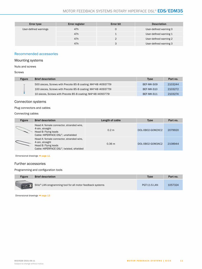
error type error register error bit description
User-defined warnings 47h 0 User-defined warning 0
47h 1 User-defined warning 1
47h 2 User-defined warning 2
47h 3 User-defined warning 3
Recommended accessories
Mounting systems
Nuts and screws
Screws
figure brief description type Part no.
500 pieces, Screws with Precote 85-8 coating; M4*48 (4093779) BEF-MK-S09 2103244
100 pieces, Screws with Precote 85-8 coating; M4*48 (4093779) BEF-MK-S10 2103272
10 pieces, Screws with Precote 85-8 coating; M4*48 (4093779) BEF-MK-S11 2103274
Connection systems
Plug connectors and cables
Connecting cables
figure brief description Length of cable type Part no.
Head A: female connector, stranded wire, 4-pin, straightHead B: Flying leadsCable: HIPERFACE DSL®, unshielded
0.2 m DOL-0B02-G0M2XC2 2079920
Head A: female connector, stranded wire, 4-pin, straightHead B: Flying leadsCable: HIPERFACE DSL®, twisted, shielded
0.36 m DOL-0B02-G0M3AC2 2108944
Dimensional drawings g page 11
Further accessories
Programming and configuration tools
figure brief description type Part no.
SVip® LAN programming tool for all motor feedback systems PGT-11-S LAN 1057324
Dimensional drawings g page 13
ABCDEF
HIJKLMNOPQRST
M o t o r f e e d b a c k s y s t e M s | s I c k 8023528/2021-08-11Subject to change without notice
1 2
eds/edM35 MOTOR FEEDBACK SYSTEMS ROTARY HIPERFACE DSL®
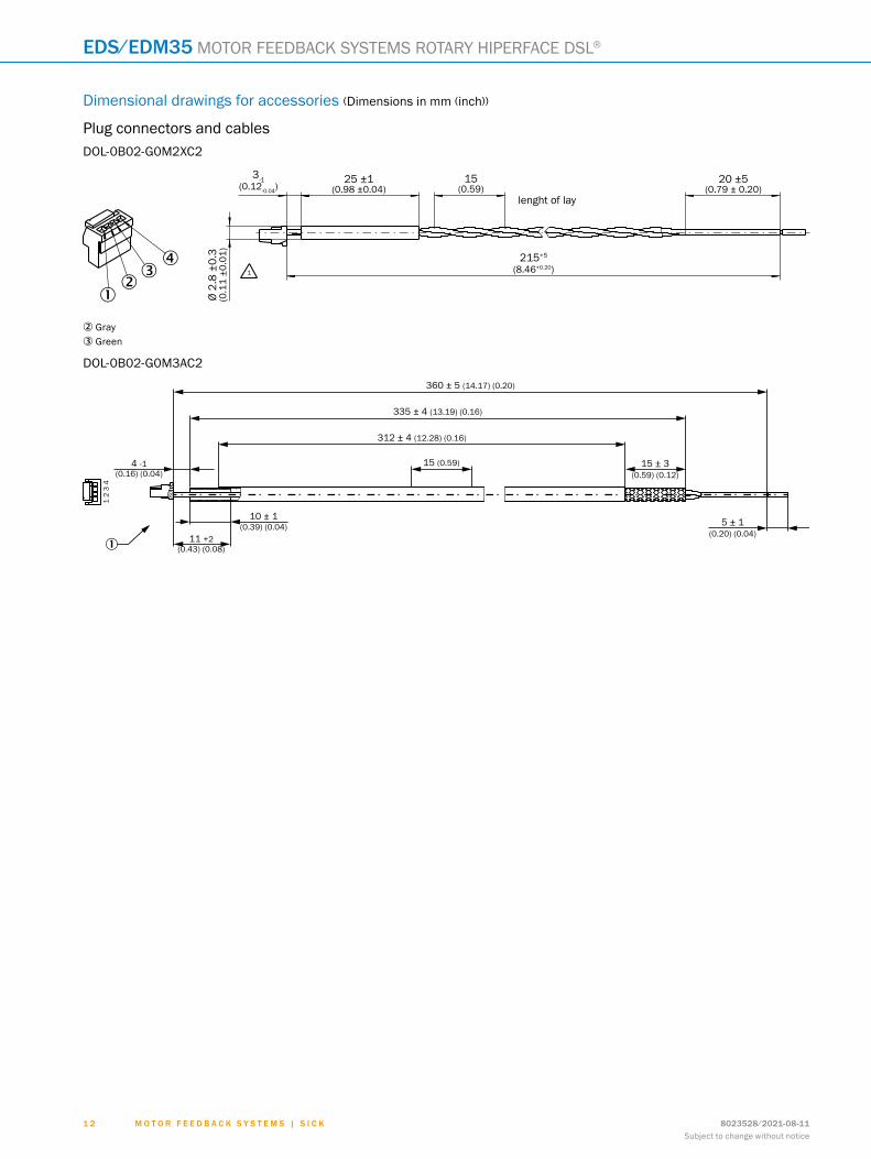
Dimensional drawings for accessories (Dimensions in mm (inch))
Plug connectors and cablesDOL-0B02-G0M2XC2
20 ±5(0.79 ± 0.20)
15(0.59)
25 ±1(0.98 ±0.04)
3-1(0.12-0.04)
Ø 2.
8 ±0
.3(0
.11
±0.0
1) 215+5
(8.46+0.20)
lenght of lay
���
�1
2 Gray3 Green
DOL-0B02-G0M3AC2
1 2
3 4
360 ± 5 (14.17) (0.20)
312 ± 4 (12.28) (0.16)
15 ± 3(0.59) (0.12)
5 ± 1(0.20) (0.04)
1
335 ± 4 (13.19) (0.16)
15 (0.59)4 -1(0.16) (0.04)
10 ± 1(0.39) (0.04)
11 +2(0.43) (0.08)
ABCDEF
HIJKLMNOPQRST

M o t o r f e e d b a c k s y s t e M s | s I c k8023528/2021-08-11Subject to change without notice
1 3
MOTOR FEEDBACK SYSTEMS ROTARY HIPERFACE DSL® eds/edM35
Programming and configuration toolsPGT-11-S LAN
190 ±2 (7.48)
179 ±1 (7.05)
162.5 ±1 (6.40)
19.5(0.78)
108.9 (4.29)
83.2 (3.28)
44.2 (1.74)
22.2 (0.87)
22.3
(0.8
8)
49.5
4 (1
.95)
102
±2 (4
.02)
27.9
(1.1
0)
108.
9 (4
.29)
ABCDEF
HIJKLMNOPQRST
M o t o r f e e d b a c k s y s t e M s | s I c k 8023528/2021-08-11Subject to change without notice
1 4
sHub® MOTOR FEEDBACK SYSTEMS ROTARY HIPERFACE DSL®
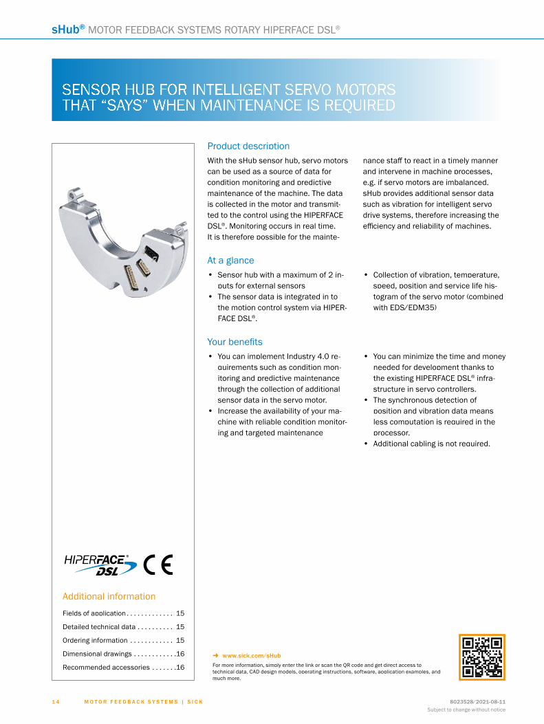
Product descriptionWith the sHub sensor hub, servo motors can be used as a source of data for condition monitoring and predictive maintenance of the machine. The data is collected in the motor and transmit-ted to the control using the HIPERFACE DSL®. Monitoring occurs in real time. It is therefore possible for the mainte-
nance staff to react in a timely manner and intervene in machine processes, e.g. if servo motors are imbalanced. sHub provides additional sensor data such as vibration for intelligent servo drive systems, therefore increasing the efficiency and reliability of machines.
At a glance• Sensor hub with a maximum of 2 in-
puts for external sensors• The sensor data is integrated in to
the motion control system via HIPER-FACE DSL®.
• Collection of vibration, temperature, speed, position and service life his-togram of the servo motor (combined with EDS/EDM35)
Your benefits• You can implement Industry 4.0 re-
quirements such as condition mon-itoring and predictive maintenance through the collection of additional sensor data in the servo motor.
• Increase the availability of your ma-chine with reliable condition monitor-ing and targeted maintenance
• You can minimize the time and money needed for development thanks to the existing HIPERFACE DSL® infra-structure in servo controllers.
• The synchronous detection of position and vibration data means less computation is required in the processor.
• Additional cabling is not required.
sHub®
SENSOR HUB FOR INTELLIGENT SERVO MOTORS THAT “SAYS” WHEN MAINTENANCE IS REQUIRED
Additional information
Fields of application . . . . . . . . . . . . . 15
Detailed technical data . . . . . . . . . . 15
Ordering information . . . . . . . . . . . . 15
Dimensional drawings . . . . . . . . . . . .16
Recommended accessories . . . . . . .16
- www.sick.com/sHubFor more information, simply enter the link or scan the QR code and get direct access to technical data, CAD design models, operating instructions, software, application examples, and much more.
ABCDEF
HIJKLMNOPQRST
M o t o r f e e d b a c k s y s t e M s | s I c k8023528/2021-08-11Subject to change without notice
1 5
MOTOR FEEDBACK SYSTEMS ROTARY HIPERFACE DSL® sHub®
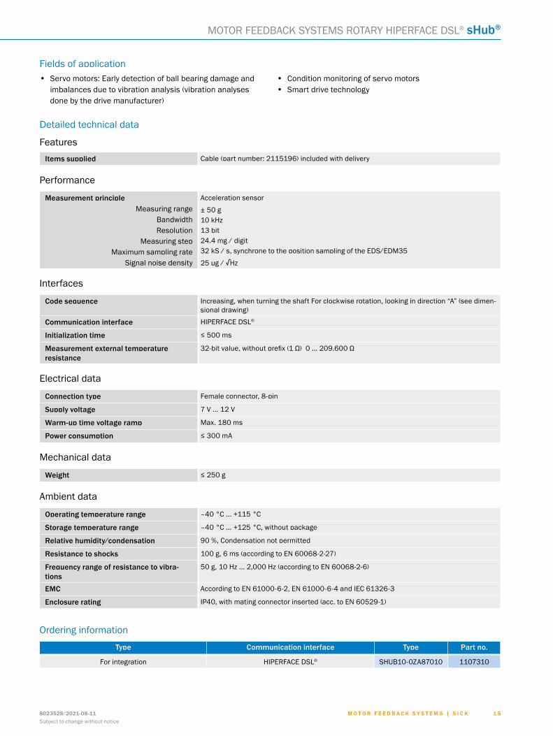
Fields of application• Servo motors: Early detection of ball bearing damage and
imbalances due to vibration analysis (vibration analyses done by the drive manufacturer)
• Condition monitoring of servo motors• Smart drive technology
Detailed technical data
FeaturesItems supplied Cable (part number: 2115196) included with delivery
Performance
Measurement principleMeasuring range
BandwidthResolution
Measuring stepMaximum sampling rate
Signal noise density
Acceleration sensor
± 50 g10 kHz13 bit24.4 mg / digit32 kS / s, synchrone to the position sampling of the EDS/EDM35
25 μg / √Hz
Interfaces
code sequence Increasing, when turning the shaft For clockwise rotation, looking in direction “A” (see dimen-sional drawing)
communication interface HIPERFACE DSL®
Initialization time ≤ 500 ms
Measurement external temperature resistance
32-bit value, without prefix (1 Ω) 0 ... 209.600 Ω
Electrical data
connection type Female connector, 8-pin
supply voltage 7 V ... 12 V
Warm-up time voltage ramp Max. 180 ms
Power consumption ≤ 300 mA
Mechanical data
Weight ≤ 250 g
Ambient data
operating temperature range –40 °C ... +115 °C
storage temperature range –40 °C ... +125 °C, without package
relative humidity/condensation 90 %, Condensation not permitted
resistance to shocks 100 g, 6 ms (according to EN 60068-2-27)
frequency range of resistance to vibra-tions
50 g, 10 Hz ... 2,000 Hz (according to EN 60068-2-6)
eMc According to EN 61000-6-2, EN 61000-6-4 and IEC 61326-3
enclosure rating IP40, with mating connector inserted (acc. to EN 60529-1)
Ordering information
type communication interface type Part no.
For integration HIPERFACE DSL® SHUB10-0ZA87010 1107310
ABCDEF
HIJKLMNOPQRST
M o t o r f e e d b a c k s y s t e M s | s I c k 8023528/2021-08-11Subject to change without notice
1 6
sHub® MOTOR FEEDBACK SYSTEMS ROTARY HIPERFACE DSL®
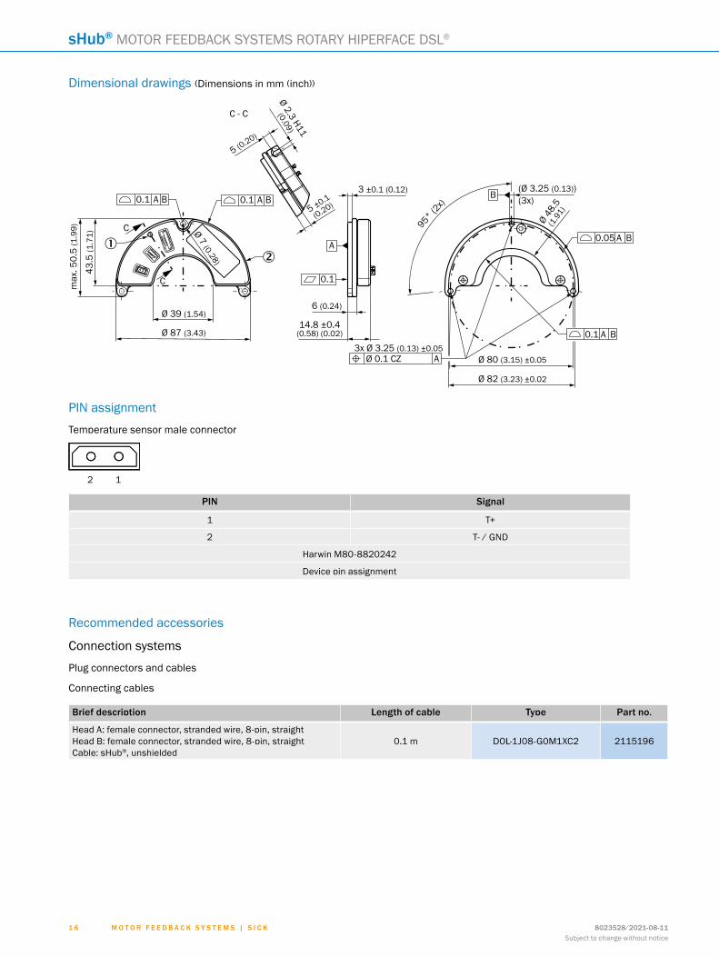
Dimensional drawings (Dimensions in mm (inch))
C - C
max
. 50.
5 (1
.99)
43.5
(1.7
1)
Ø 2.3 H11
(0.09)
5 (0.20)
5 ±0.1
(0.20)
Ø 7 (0.28)
Ø 39 (1.54)
Ø 87 (3.43)
3 ±0.1 (0.12)
95° (2x)
6 (0.24)
14.8 ±0.4(0.58) (0.02)
3x Ø 3.25 (0.13) ±0.05Ø 80 (3.15) ±0.05
Ø 82 (3.23) ±0.02
(Ø 3.25 (0.13))(3x)
Ø 48.
5(1
.91)
0.1 A B 0.1 A
A
B
C
C 0.1
Ø 0.1 CZ A
0.1 A B
0.05 A B
B
12
PIN assignment
Temperature sensor male connector
2 1
PIN signal
1 T+
2 T- / GND
Harwin M80-8820242
Device pin assignment
Recommended accessories
Connection systems
Plug connectors and cables
Connecting cables
brief description Length of cable type Part no.
Head A: female connector, stranded wire, 8-pin, straightHead B: female connector, stranded wire, 8-pin, straightCable: sHub®, unshielded
0.1 m DOL-1J08-G0M1XC2 2115196
ABCDEF
HIJKLMNOPQRST

M o t o r f e e d b a c k s y s t e M s | s I c k8023528/2021-08-11Subject to change without notice
1 7
NOTES
ABCDEF
HIJKLMNOPQRST

M o t o r f e e d b a c k s y s t e M s | s I c k 8023528/2021-08-11Subject to change without notice
1 8
NOTES
ABCDEF
HIJKLMNOPQRST

SERVICES
WORKING WITH SICK IN A DIGITAL WORLD
Find a suitable solution in next to no timeOften we know best what we need – but not necessarily where to find it right away. SICK will support you with its in-depth expertise.
• Online product catalog – our digital flagship - www.sick.com/products
• Application Solver – the right sensor for selected applications - www.sick.com/applicationBased
• Online configurators and selectors – exactly the right sensor for your needs
My SICK is your personal self-service portalMy SICK is your personal self-service portal with lots of helpful information and your own individual access to the web shop. Take advantage of the wide variety of exclusive advantages on offer:
Your benefits • Open around the clock • Clear product information • Company-specific price conditions • Convenience during the ordering process • Document overview • Availability and delivery times
Register now:- www.sick.com/myBenefits
Making your digital business environment comfortable
247
Get ahead with digital knowledge transfer and digital services
• Digital Customer Trainings - www.sick.com/c/g300887 • Digital Service Catalog - cloud.sick.com • SICK AppPool - apppool.cloud.sick.com
Irrtümer und Änderungen vorbehalten1 9M O T O R F E E D B A C K S Y S T E M | S I C K8023528/2021-08-11

SICK AG | Waldkirch | Germany | www.sick.com
SICK AT A GLANCESICK is a leading manufacturer of intelligent sensors and sensor solutions for industrial applications. With more than 10,400 employees and over 50 subsidiaries and equity investments as well as numerous agencies worldwide, SICK is always close to its customers. A unique range of products and services creates the perfect basis for controlling processes securely and efficiently, protecting individuals from accidents, and preventing damage to the environment.
SICK has extensive experience in various industries and understands their processes and requirements. With intelligent sensors, SICK delivers exactly what the customers need. In application centers in Europe, Asia, and North America, system solutions are tested and optimized in accordance with customer specifica-tions. All this makes SICK a reliable supplier and development partner.
Comprehensive services round out the offering: SICK LifeTime Services provide support throughout the machine life cycle and ensure safety and productivity.
That is “Sensor Intelligence.”
Worldwide presence:
Australia, Austria, Belgium, Brazil, Canada, Chile, China, Czech Republic, Denmark, Finland, France, Germany, Great Britain, Hungary, Hong Kong, India, Israel, Italy, Japan, Malaysia, Mexico, Netherlands, New Zealand, Norway, Poland, Romania, Russia, Singapore, Slovakia, Slovenia, South Africa, South Korea, Spain, Sweden, Switzerland, Taiwan, Thailand, Turkey, United Arab Emirates, USA, Vietnam.
Detailed addresses and further locations - www.sick.com
8023
528/
2021
-08-
11 ∙
AB_0
7 ∙ P
re U
Smod
en5
1